cable-catenary large antenna concept · the cable-catenary antenna the cable-catenary antenna (cca)...
TRANSCRIPT

CABLE-CATENARY LARGE ANTENNA CONCEPT
W. AKLE TRW
SPACE AND TECHNOLOGY GROUP REDONDO BEACH, CA
LARGE SPACE ANTENNA SYSTEMS TECHNOLOGY DECEMBER 4 - 6 , 1984
271
https://ntrs.nasa.gov/search.jsp?R=19850015518 2020-02-15T18:03:00+00:00Z
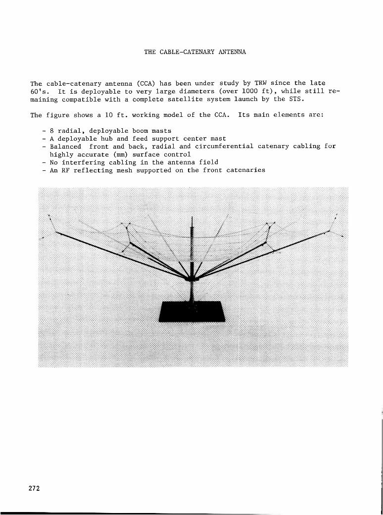
THE CABLE-CATENARY ANTENNA
The cable-catenary antenna (CCA) has been under study by TRW since the late 6 0 ' s . maining compatible with a complete satellite system launch by the STS.
The figure shows a 10 ft. working model of the CCA. Its main elements are:
It is deployable to very large diameters (over 1000 ft), while still re-
8 radial, deployable boom masts A deployable hub and feed support center mast Balanced front and back, radial and circumferential catenary cabling for highly accurate (mm) surface control No interfering cabling in the antenna field An RF reflecting mesh supported on the front catenaries
272

CABLE-CATENARY ANTENNA - SATELLITE SYSTEM DEPLOYED CONFIGURATION
The CCA is shown deployed i n a t y p i c a l l a r g e communication sa te l l i t e conf igura t ion .
The sa te l l i t e main bus is loca ted behind t h e f o c a l plane ( feeds) . antenna a p e r t u r e shadowing, t h e s o l a r a r r a y wings can be extended f u r t h e r . tude con t ro l a u t h o r i t y can be enhanced by l o c a t i n g c o n t r o l t h r u s t e r s f a r appar t a t t h e ends of t h e c e n t e r m a s t .
To preclude A t t i -
The number of c a t e n a r i e s t o form t h e r e f l e c t o r plane i s dependent on t h e requi red opera t ing frequency and s ide lobe con t ro l .
so L
RADIAL, CIRCUMFERENTIAL CATENARIES LOWER CATENARY
CATENARY DROP LINES
ALTERNATE SOLAR ARRAY AND-
ITUDE CONTROI AST STAB I L-
IZATION CORDS
BOOM MAST (8)
ORBITER TIP BEAMS (16)'
273
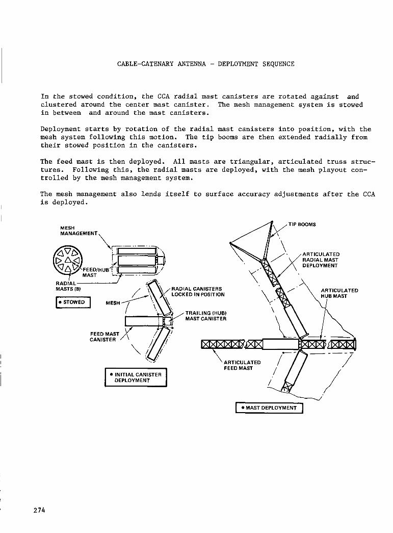
CABLE-CATENARY ANTENNA - DEPLOYMENT SEQUENCE
In the stowed condition, the CCA radial mast canisters are rotated against clustered around the center mast canister. The mesh management system is stowed in between and around the mast canisters.
and
Deployment starts by rotation of the radial mast canisters into position, with the mesh system following this motion. their stowed position in the canisters.
The tip booms are then extended radially from
The feed mast is then deployed. All masts are triangular, articulated truss struc- tures. Following this, the radial masts are deployed, with the mesh playout con- trolled by the mesh management system.
The mesh management also lends itself to surface accuracy adjustments after the CCA is deployed.
MESH MANAG EM ENT
ARTICULATED RADIAL MAST DEPLOYMENT
RADIAL CANISTERS LOCKED IN POSITION
RADIAL MASTS (8)
TRAILING (HUB) MAST CANISTER
ARTICULATED
FEED MAST CANISTER
274

CABLE-CATENARY ANTENNA SATELLITE SYSTEM - STOWED CONFIGURATION
The CCA stows very compactly; less than 10 ft. length for a 300-m aperture. This feature, coupled with a sturdy canister cluster, allows for efficient integration in the Orbiter cargo bay of the complete spacecraft and its Orbital Transfer Vehicle (OTV).
The OTV illustrated is in the Centaur G class; a length allowance of 22 ft assumed. bus and payload. length/volume limited in the Orbiter cargo bay.
is This leaves approximately 25 ft
On this basis, the system may be weight limited rather than of effective length for the spacecraft
0,RBlTER CARGO BAY ?Tv
ADAPTER / I ORBITER f C A R G O B A Y 7
J
/ SPACECRAFT BUS / ' FEEDSYSTEM
\ FEED/HUB MAST \
RADIAL BOOM CLUSTER (8 )
CABLE -CATENARY ANTENNA
275
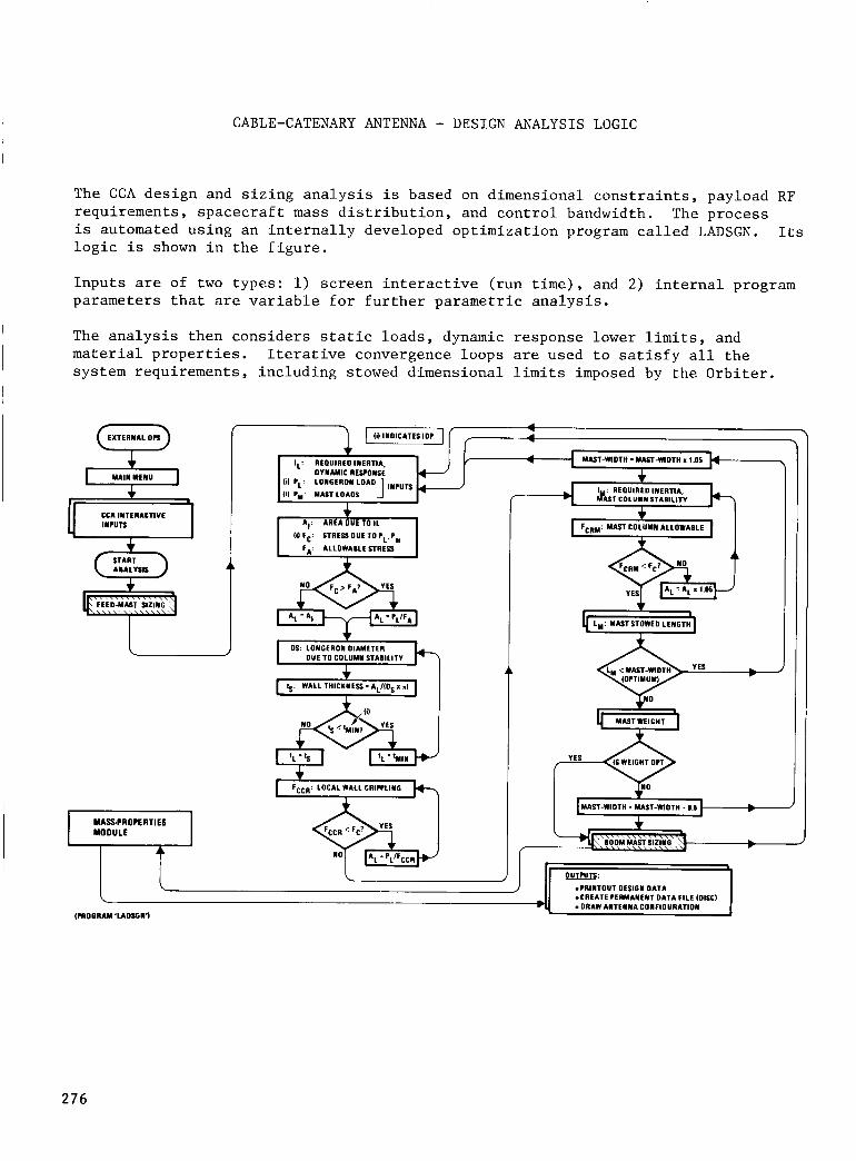
CABLE-CATENARY ANTENNA - DESIGN ANALYSIS LOGIC
The CCA design and sizing analysis is based on dimensional constraints, payload RF requirements, spacecraft mass distribution, and control bandwidth. The process is automated using an internally developed optimization program called LADSGN. logic is shown in the figure.
Its
Inputs are of two types: 1) screen interactive (run time), and 2) internal program parameters that are variable f o r further parametric analysis.
The analysis then considers static loads, dynamic response lower limits, and material properties. system requirements, including stowed dimensional limits imposed by the Orbiter.
Iterative convergence loops are used to satisfy all the
EXTERNAL on Q CCA IMTERACTIVE
MASPROPERTIES MOOULE
AI: AREA OUE TO I L
FA: ALLOWABLESTRESS ( i l Fc: STRESS OUE TO IL.Im
AL = AI AL = I L / F A
DS: LOMGEROM DIAMETER DUE TO COLUMN STABILITY
FCCR: LOCAL WALL CRIWLIMG
F C R ~ : MAST COLUMN ALLOWABLE - 1 - Ly: MASTSTOWEO LEMCTH
MASTWEIGHT - m T S :
b .?RIMTOUT OESIGM DATA .CREATE IERMANEMT DATA FILE (DISC)
(PROGRAM 'LAOIGY'I
I 276

CABLE-CATENARY ANTENNA - SIZING ANALYSIS OUTPUT
The analysis results in the figure consist of the input system parameters the output dimensional and weight data for all the critical CCA elements. mass properties are generated for use by other program modules, such as attitude control.
and Detailed
09t31t58 20 Oct 1983 'LADSGN' PROGRAM ,Y.dm AKLE , VERSION 1.1
nNTENNn DIAMETER ( F t ) - 100 FOCAL LENCTH/DIAMETER ( F I D ) = .6 OPERATING RF FREQUENCY (CHz)* 2 SURFACE ACCURACY (YAVELENCTH/MAX ERROR)- 16 M A I N ELEMENT STRUCTURAL RESPONSE (HI)- .I
NUMBER OF CURES - 14
*****lt CADLE-CATENARY ANTENNA G I Z I N C ANALYSIS *******
OPERnTxNc RF YAVELENCTH (F t )= .5
OFF-POINTING ANGLE FROM NfiDIR (D.9)- 8 11111111I111I111-.1111----1*=m~99-==*---1=-----=----
MASTS S I Z E D TO O P T I M I Z E YEIGHT, Y I T H I N MAX ALLOYED Y I D T H
--I-- FEED nnsf DESIGN DnTn OUTPUTI MLST 6ESIGNED BY LONGERON BUCKLING DUE TO GENERAL COMPRESSIVE MAST LOADS (LbI- 1 7 0 a MATER InL A L L o u n n L E STRESS IS cn I T I C A L 1
MAST DEPLOYED LENGTH ( F t ) - 67
nnsr B n y uzoiH=Bnv mrwr (Ft)- i MAST STOYED'LENGTH ( F t ) - 2 . 6
NUMBER OF B w s = 67
LONGERON DILMETER (Ft)- .0289 LONGERON THICKNES8(Ft )m .00140
CANISTER YEICHT ( L b ) m 19.0 LONGERON YEIGHT (Lb)- 15.4 BATTENS UEICHT (Lb). 7.7 D x n c o N n L s YEICHT a b ) - 4.4 JOINTS YEIGHT (Lb)- 22.1 MECHANISM YEIGHT (Lbl- 12.0
----=--*-- TOTAL MAST YEICHT eo
--=-- c n T E N n R i BooM-MnsT DESIGN DnTn OUTPUT, MAST DESIGNED F Y LONGERON BUCKLING DUE TO GENERAL COMPRESSIVE MAST LOADS (Lb)- 1269 tmTEuxnL ALLOYABLE STRESS IS c R x T x c n L ~
Mnsi DEPLOYED LENGTH (Ft) - SO
MAST FAY YZDTH=FAY HEIGHT (F t ) - I MAST STWED LENGTH ( F t ) - 1.9
NUMBER OF w y s I 50
LONGERON D I M E T E R (Ft)- .02SI LONGERON lHICKNESS(Ft)~ , 00239
CANISTER YEIGHT (Lb)- 19.0 LONGERON YEICHT (Lb)- 4.8 BATTENS YEIGHT (Lb)- 2.4 DIAGONAL8 YEICHT (Lb)- 2.5 JOINTS YEICHT (Lb)- 16.5 MECHANISM YEIGHT (Lb)= 12.0
-==-==---- TOTAL MnsT YEICHT a b ) -
a t s i t C n K E - c n T E N n n y ANTENNA Mnss PROPERTIES * *a la
WTEWNA MESH MESH YEIGHT (Lb)- 19 RADIAL CATENARIES WIGHT - I2 CIRCUMFERENTIAL CnrENnRxEs- 2 T I P MASTS YEICHT 9 81 MECHANISHS YEICHT I 7 ...........................................
TOTAL ANTENNA YEIGHT (Lb) I 664. ANTENNA CG FROM PARABOLA APPEX ( F t ) - + 7 . 0
ANTENNA I N E R T I A (PERPENDICULAR TO A X I S ) ( L b - F t ' 2 ) = + 6 . O l E * 0 5 ANTENNA I N E R T I A (PARALLEL TO A X I S ) ( L b - F t ' 2 ) = 4 7 . 2 7 E + 0 5 ANTENNA CROSS I N E R T I A ( L b - F t ' 2 ) ~ 4 0 . 0 0 E t 0 0 OFF-PUINTINC ANGLE FROM NADIR (Dcq)= 9 . 0
57
277

CABLE-CATENARY ANTENNA - TYPICAL PARAMETRIC DESIGN DATA
Program LADSGN i s used t o g e n e r a t e a v a r i e t y of CCA p a r a m e t r i c d e s i g n d a t a . and stowed dimensions, s e n s i t i v i t y t o f o c a l l e n g t h , a p e r t u r e , dynamic r e s p o n s e lower l i m i t f requency , and o t h e r parameters are i l l u s t r a t e d i n t h e f i g u r e f o r low RF frequency (MHz) systems.
Weight
The CCA is a h i g h l y a d a p t a b l e des ign . It is a p p l i c a b l e t o many of t h e proposed s p a c e c r a f t r e q u i r i n g l a r g e a p e r t u r e . The p r e l i m i n a r y t o o l s r e q u i r e d t o suppor t system t r a d e s and s t u d i e s are a v a i l a b l e i n c l u d i n g c o s t a n a l y s i s .
TRW b e l i e v e s t h a t t h i s concept i s c o m p e t i t i v e and should be cons idered i n system s t u d i e s c o n s i d e r i n g l a r g e an tennas .
i a - C l l l t A U n d '
ASE ALLOWANCE
AlrCIIOXIYATE ANTENNA ALLOWANCE
o iwn SVSTEY
.. M I c
I- M DIA; F/D - 0.4)
0.4 0.1 0.1
2 9 0
0.m 0.07 0.a 0.11 4 I 8 7
m - muxcnAcT FEED & MAIN OUS 10-
I u x ALCOIIULE
I T n W I U R A L SVSTEY
10 - con ANTENNA
I I I ,)
tn IHlI Y U T WIDTH IFIOI IFEETI
I 278