cabinet locks - dh pace
TRANSCRIPT

CABINET LOCKS
CA
BIN
ET
LO
CK
S
Distributed ByDH Pace National Key Service Center
[email protected]/BestSolutions

2 C A B I N E T
SpecificationsMaterial– Bolt is stainless steel, springs are phosphor bronze, all other parts are brass.ANSI/BHMA– Conforms to requirements of ANSI/BHMA A156.11, Grade 1Backset– 7/8"Bolt– 1 1/8" x 3/16" – 3/4" throwCase– Height 1 21/32", width 2 1/8", thickness 21/32", hole spacing 1 39/64" x 1 1/4"Cylinder diameter– 1 1/8"Cylinder length– 7-pin tumbler, 1 13/64"Finish– Base finish 606 unless otherwise specified.Keeper plate– None supplied.
TABLE OF CONTENTSL Series Page
3L Features/specifications . . . . . . . . . . . . . . . . . . .23L How to Order . . . . . . . . . . . . . . . . . . . . . . . . . .25L Latchbolt specifications/mounting positions . . .35L Deadbolt mounting positions/strikes . . . . . . . . .45L How to Order . . . . . . . . . . . . . . . . . . . . . . . . . .48L Features/specifications . . . . . . . . . . . . . . . . . . .5
E Series1E Features/spec’s/ How to Order . . . . . . . . . . . . .55E Features/spec’s/ How to Order . . . . . . . . . . . . .6
3L S
ER
IES
Products protected by one or more of the following patents:U.S.: Canada:
4531390 4531389 4633690 12292344663839 4075878 46163944055973 4768360 D2900854722204 4843852
HOW TO ORDER 3L
3LSeries
3L– coin box lock
7Core
7– 7 pin housingaccepts allBest cores
RMountingHousingR– rim
DLatchType
D– deadbolt
606Standard
Finish606 612
626(cylinder only)
2HandType
2– vertical
3L SERIES DEADBOLT
3L7RD2(Vertical Only)
Operation–Deadbolt locked and unlocked by key. Must be locked by key after door is closed. Key may be withdrawn in lockedposition and unlocked position.
P Series Page2P Features/specifications . . . . . . . . . . . . . . . . . .7
Patented Keying . . . . . . . . . . . . . . . . . . . . . . . . . .7S Series
2S Functions/spec’s/ How to Order . . . . . . . . . . .83S Features/spec’s/ How to Order . . . . . . . . . . . .9
Service Equipment . . . . . . . . . . . . . . . . . . . .10-11
3L O C K S
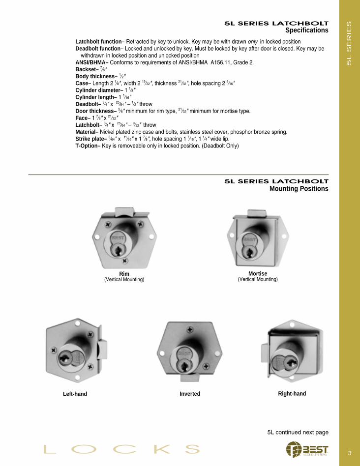
5L SERIES LATCHBOLTSpecifications
Latchbolt function– Retracted by key to unlock. Key may be with drawn only in locked positionDeadbolt function– Locked and unlocked by key. Must be locked by key after door is closed. Key may be
withdrawn in locked position and unlocked positionANSI/BHMA– Conforms to requirements of ANSI/BHMA A156.11, Grade 2Backset– 7⁄8"Body thickness– 1⁄2"Case– Length 2 1⁄8", width 2 19⁄32", thickness 21⁄32", hole spacing 2 3⁄16"Cylinder diameter– 1 1⁄8"Cylinder length– 1 1⁄16"Deadbolt– 3⁄4" x 25⁄64" – 1⁄2" throwDoor thickness– 5⁄8" minimum for rim type, 21⁄32" minimum for mortise type.Face– 1 7⁄8" x 21⁄32"Latchbolt– 3⁄4" x 25⁄64" – 9⁄32" throwMaterial– Nickel plated zinc case and bolts, stainless steel cover, phosphor bronze spring.Strike plate– 3⁄64" x 11⁄16" x 1 7⁄8", hole spacing 1 7⁄16", 1 1⁄4" wide lip.T-Option– Key is removeable only in locked position. (Deadbolt Only)
Mortise(Vertical Mounting)
5L S
ER
IES
Rim(Vertical Mounting)
5L SERIES LATCHBOLTMounting Positions
Left-hand Inverted Right-hand
5L continued next page
4 C A B I N E T
5L D
EA
DB
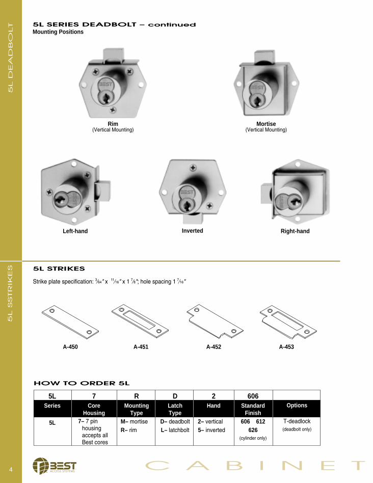
OLT 5L SERIES DEADBOLT – continued
Mounting Positions
Rim(Vertical Mounting)
Mortise(Vertical Mounting)
Left-hand Inverted Right-hand
5LSeries
5L
DLatchType
D– deadboltL– latchbolt
606Standard
Finish606 612
626(cylinder only)
2Hand
2– vertical5– inverted
Options
T-deadlock(deadbolt only)
5L STRIKES
HOW TO ORDER 5L
A-450 A-451 A-453A-452
RMounting
TypeM– mortiseR– rim
7Core
Housing7– 7 pin
housing accepts allBest cores
5L S
STR
IKES
Strike plate specification: 3⁄64" x 11⁄16" x 1 7⁄8"; hole spacing 1 7⁄16"
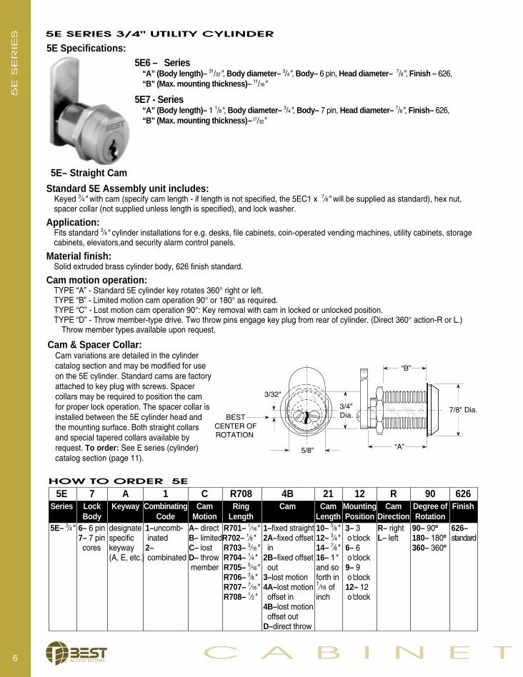
1E7D4Direct motion cam prevents key from being with-drawn in unlocked position. Reversible cam maybe assembled for required hand at installation.
1E7E4270° lost motion cam permits key to bewithdrawn when locked or unlocked.
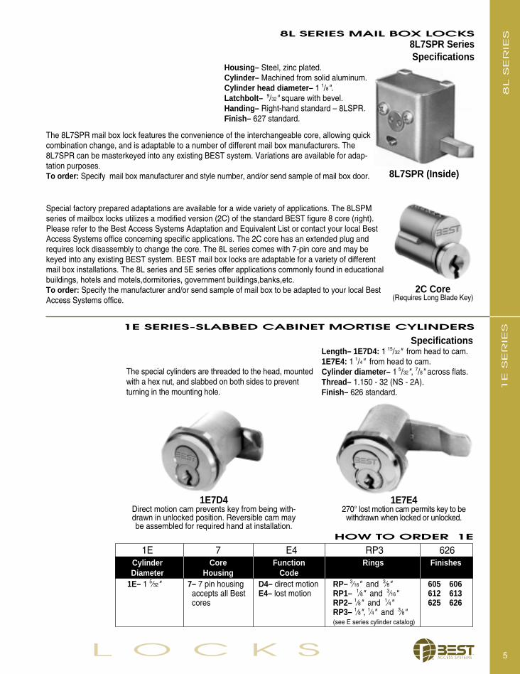
Special factory prepared adaptations are available for a wide variety of applications. The 8LSPMseries of mailbox locks utilizes a modified version (2C) of the standard BEST figure 8 core (right).Please refer to the Best Access Systems Adaptation and Equivalent List or contact your local BestAccess Systems office concerning specific applications. The 2C core has an extended plug andrequires lock disassembly to change the core. The 8L series comes with 7-pin core and may bekeyed into any existing BEST system. BEST mail box locks are adaptable for a variety of differentmail box installations. The 8L series and 5E series offer applications commonly found in educationalbuildings, hotels and motels,dormitories, government buildings,banks,etc. To order: Specify the manufacturer and/or send sample of mail box to be adapted to your local BestAccess Systems office.
5L O C K S
1E 7 E4 RP3 626Cylinder Core Function Rings Finishes Diameter Housing Code
1E– 1 5⁄32" 7– 7 pin housing D4– direct motion RP– 3⁄16" and 3⁄8" 605 606 accepts all Best E4– lost motion RP1– 1⁄8" and 3⁄16" 612 613cores RP2– 1⁄8" and 1⁄4" 625 626
RP3– 1⁄8", 1⁄4" and 3⁄8"(see E series cylinder catalog)
The special cylinders are threaded to the head, mountedwith a hex nut, and slabbed on both sides to preventturning in the mounting hole.
HOW TO ORDER 1E
8L7SPR (Inside)
SpecificationsHousing– Steel, zinc plated.Cylinder– Machined from solid aluminum.Cylinder head diameter– 1 1/8".Latchbolt– 9/32" square with bevel.Handing– Right-hand standard – 8LSPR.Finish– 627 standard.
2C Core(Requires Long Blade Key)
8L S
ER
IES
1E S
ER
IES1E SERIES-SLABBED CABINET MORTISE CYLINDERS
The 8L7SPR mail box lock features the convenience of the interchangeable core, allowing quickcombination change, and is adaptable to a number of different mail box manufacturers. The8L7SPR can be masterkeyed into any existing BEST system. Variations are available for adap-tation purposes.To order: Specify mail box manufacturer and style number, and/or send sample of mail box door.
SpecificationsLength– 1E7D4: 1 15/32" from head to cam.1E7E4: 1 1/4" from head to cam.Cylinder diameter– 1 5/32", 7/8" across flats.Thread– 1.150 - 32 (NS - 2A).Finish– 626 standard.
8L SERIES MAIL BOX LOCKS8L7SPR Series
6 C A B I N E T
“B”
“A”5/8"
7/8" Dia.
3/32"
BESTCENTER OFROTATION
3/4"Dia.
5E– Straight Cam
5E Specifications:5E6 – Series
“A” (Body length)– 31/32", Body diameter– 3/4", Body– 6 pin, Head diameter– 7/8", Finish – 626,“B” (Max. mounting thickness)– 11/16"
5E7 - Series“A” (Body length)– 1 1/8", Body diameter– 3/4", Body– 7 pin, Head diameter– 7/8", Finish– 626, “B” (Max. mounting thickness)– 27/32"
Standard 5E Assembly unit includes:Keyed 3⁄4" with cam (specify cam length - if length is not specified, the 5EC1 x 7⁄8" will be supplied as standard), hex nut,spacer collar (not supplied unless length is specified), and lock washer.
Application: Fits standard 3⁄4" cylinder installations for e.g. desks, file cabinets, coin-operated vending machines, utility cabinets, storage cabinets, elevators,and security alarm control panels.
Material finish: Solid extruded brass cylinder body, 626 finish standard.
Cam motion operation: TYPE “A” - Standard 5E cylinder key rotates 360° right or left.TYPE “B” - Limited motion cam operation 90° or 180° as required.TYPE “C” - Lost motion cam operation 90°: Key removal with cam in locked or unlocked position.TYPE “D” - Throw member-type drive. Two throw pins engage key plug from rear of cylinder. (Direct 360° action-R or L.)
Throw member types available upon request.
HOW TO ORDER 5E
5E S
ER
IES 5E SERIES 3/4" UTILITY CYLINDER
Cam & Spacer Collar:Cam variations are detailed in the cylinder catalog section and may be modified for use on the 5E cylinder. Standard cams are factoryattached to key plug with screws. Spacer collars may be required to position the cam for proper lock operation. The spacer collar is installed between the 5E cylinder head and the mounting surface. Both straight collars and special tapered collars available by request. To order: See E series (cylinder) catalog section (page 11).
5E 7 A 1 C R708 4B 21 12 R 90 626Series Lock Keyway Combinating Cam Ring Cam Cam Mounting Cam Degree of Finish
Body Code Motion Length Length Position Direction Rotation5E– 3⁄4" 6– 6 pin designate 1–uncomb- A– direct R701– 1⁄16" 1–fixed straight 10– 5⁄8" 3– 3 R– right 90– 90º 626–
7– 7 pin specific inated B– limitedR702– 1⁄8" 2A–fixed offset 12– 3⁄4" o'clock L– left 180– 180º standardcores keyway 2– C– lost R703– 3⁄16" in 14– 7⁄8" 6– 6 360– 360º
(A, E, etc.) combinated D– throw R704– 1⁄4" 2B–fixed offset 16– 1" o'clockmember R705– 5⁄16" out and so 9– 9
R706– 3⁄8" 3–lost motion forth in o'clockR707– 7⁄16" 4A–lost motion 1⁄16 of 12– 12 R708– 1⁄2" offset in inch o'clock
4B–lost motionoffset out
D–direct throw

Dimensions in inchesVertical Mounting Slot
A B C D E F G H I J K L2P73
(7Barrel) 2 9⁄32" 1⁄4" 19⁄32" 1 1⁄8" 3⁄4" 5⁄16" 1⁄8" 5⁄32" #6-32 5⁄32"Horizontal Mounting Slot
2P74(7Barrel) 2 9⁄32" 1⁄4" 19⁄32" 1 1⁄8" 3⁄4" 5⁄16" 1⁄8" 5⁄32" #6-32 5⁄32"
7L O C K S
SpecificationsMaterial– All parts are solid brass; phosphor bronze springs.Dimensions– See illustrations and table below.Finish– 2P Series 626 (satin chrome) standard finish. 5P
series finish to match satin chrome. (7 pin only). 2P
SER
IES2P SERIES PUSH LOCKS FOR FILE CABINETS
Two types of file cabinet push locks are available from BEST. The 2P series incorporates the BEST interchangeable core andrequires special cabinet preparation. The 5P series replaces standard industry size file cabinet locks without modification oflock opening, but does not have interchangeable core features. Both may be keyed individually, keyed alike, masterkeyed orgrand-masterkeyed with other BEST locks of any type. To order: Specify proper lock, finish and keying instructions.
2P73 Vertical mounting slot 2P74 Horizontal mounting slot
2P Series Specifications
PATENTED KEYING
PA
TEN
TED
KEY
ING
BEST Peaks®
Patented Keying
BEST Peaks®– For advanced solutions in key control and security, BEST offers Peaks®, the most adaptable and cost effective patented keying system on the market. The patented mechanism ensures that cylinders and cores will only operate with the Peaks® keys, which are only available through authorized BEST distributors.
For BEST products, Peaks® offers the security and convenience of a patented solution for interchangeable core. Peaks® is also available to adapt to a wide variety of locksfrom other manufacturers. All cylinders can be keyed into the same system, providing you the ability to operate all the locks at your facility using a single key, regardless of the lock manufacturer.
8 C A B I N E T
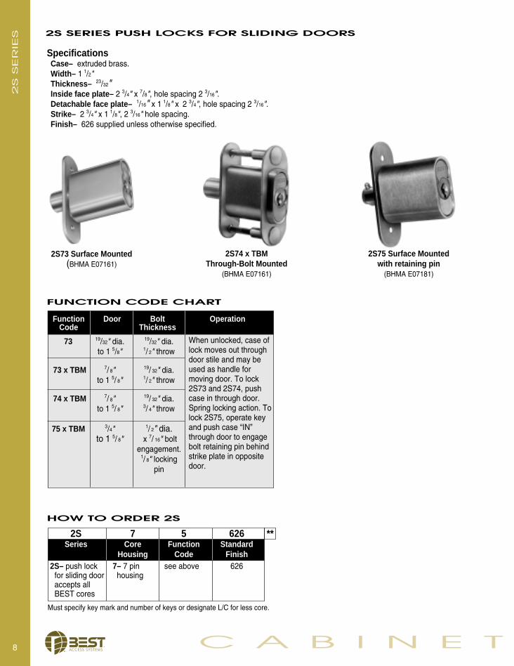
SpecificationsCase– extruded brass.Width– 1 1/2"Thickness– 23/32"Inside face plate– 2 3/4" x 7/8", hole spacing 2 3/16".Detachable face plate– 1/16" x 1 1/8" x 2 3/4", hole spacing 2 3/16".Strike– 2 3/4" x 1 1/8", 2 3/16" hole spacing.Finish– 626 supplied unless otherwise specified.
2S74 x TBM Through-Bolt Mounted
(BHMA E07161)
2S73 Surface Mounted(BHMA E07161)
2S75 Surface Mountedwith retaining pin
(BHMA E07181)
FUNCTION CODE CHART
2S S
ER
IES
73 19/32" dia. 19/32" dia.to 1 5/8" 1/ 2" throw
73 x TBM 7/ 8" 19/ 32" dia.to 1 5/ 8" 1/ 2" throw
74 x TBM 7/ 8" 19/ 32" dia.to 1 5/ 8" 3/ 4" throw
75 x TBM 3/4" 1/ 2" dia. to 1 5/ 8" x 7/ 16" bolt
engagement.1/ 8" locking
pin
When unlocked, case oflock moves out throughdoor stile and may beused as handle for moving door. To lock2S73 and 2S74, pushcase in through door.Spring locking action. Tolock 2S75, operate keyand push case “IN”through door to engagebolt retaining pin behindstrike plate in oppositedoor.
Function Door Bolt OperationCode Thickness
HOW TO ORDER 2S
2S 7 5 626 **Series Core Function Standard
Housing Code Finish2S– push lock 7– 7 pin see above 626
for sliding door housingaccepts allBEST cores
Must specify key mark and number of keys or designate L/C for less core.
2S SERIES PUSH LOCKS FOR SLIDING DOORS

SpecificationsStrike strap– stainless steel, 1/2" wide.Locking housing– aluminum.Finish– 627 aluminum only.Operation– A stainless steel strap mounts permanently on the inner sliding panel. When panels are closed, the tongue of the strike strap extends beyond the edge of the outer panel. To lock panels, slide lock housing onto overlapping tongue and up against edge of outer panel. Lock by turn of key. Key is removable in locked position only.
9L O C K S
3S SERIES SLIDING PANEL LOCKS
3S S
ER
IES
3S75
3S77
3SS1
3SS2
3SS5
SPECIFICATIONS
3S 7 5 S2 627Series Core Function Strike Finish
Housing Code Strap
3S– sliding 7– 7 pin 5– straight lock S1– 4 1/4" x 1/4" 627– standardpanel lock housing housing S2– standard unless
accepts all 7– captured panel lock otherwise specifiedBEST cores 8– housing with 1" S3– 6 1/4" x 5/16"
extension S4– 6 1/4" x 13/32"S5– 6 1/4" x 3/4"
Strike strap Length Thickness3SS1 4 1/4" 1/4"3SS2 6 1/4" 7/32"3SS3 6 1/4" 5/16"3SS4 6 1/4" 13/32"3SS5 6 1/4" 3/4"
HOW TO ORDER 3S

5E254Metal Punch and Die
This tool provides a quick method for cutting accurate 3⁄4" slabbed holes in metal cabinets in order to mount the 5E cylinder. Slabbed side prevents cylinder from turning or being forced with head wrench. To order specify: 5ED254 punch and die.
5ED253 Thread TapMatches standard 24 thread on 5E series cylinder locks.To order specify: 5ED253 thread tap
10 C A B I N E T
5ED261 Capping BlockThe capping process for single shearline 5E cylinders requires the following:
5E slide caps: 5ECP6– 6 pin5ECP7– 7 pin
5E Cylinder: 5ED261 Capping Block5ED262 Cap Depressor
5ED261– 5ECapping Block
SER
VIC
E E
QU
IPM
EN
T SERVICE EQUIPMENT
5ED253 Thread Tap
5ED254–Metal Punch and Die

11L O C K S
5ED250 Combinating Kit (single shearline)
Similar to standard CD431 kit for figure 8 cores, the single shearline kit provides a special 5ED261 capping block, springs (5ES1) and caps (5ECP)
To order specify:5ED250 - 2 (for A2 system)5ED250 - 3 (for A3 system)5ED250 - 4 (for A4 system)
Pin Segments (included in kit)Close tolerance segments assist in accurate combinating.
To order: Contact your local Best Representative.
Core Springs (included in kit)This properly sized spring facilitates consistent action in all BEST figure 8 cores.
To order specify: 22S springs.
Core Caps (included in kit)Barrels are securely sealed by applied core caps.
To order specify: 21C caps.
SER
VIC
E E
QU
IPM
EN
TSERVICE EQUIPMENT
5ED250–Combinating Kit(single shearline)
Service Equipment for 5E Cylinders (single shearline)
Best single shearline locks may be combinated to Grand Master, Master and/orany operating combinations in your BEST system. Utilizes the AD433 Key Combinator. See (D Series) Service Equipment Catalog page 3 for details.
10M 803HPB-208 Litho USA
© 2003 Best Access SystemsAll Right Reserved
CA
BIN
ET
LO
CK
S
moc.skrowyelnats.wwwmoc.sseccatseb.www
For more information on BEST’s full line of security solutions visit our web site at www.bestaccess.com or call
Product information contained in this catalog has been compiled and presented with as much care and completeness as is reasonably possible. Errors or mistakes may be present, and in many cases, reliance has been placed on information supplied by other manufacturers which may be in error or which may
e made or should beassumed or implied with regards to product information contained in this catalog. Peaks ® is a registered trademark of KABA® High Security Locks Corporation. Product Warranty – Best Access Systems warrants that all of its products sold under its trade name "BEST" are free of defects in materials, workmanshipand operation, normal wear and tear excepted, for a period of three years from the date of sale to the original purchaser. Concerning Proper Installation: Installation instructions for any Best Access Systems product should be carefully followed for proper operation of theinstalled product. If improperly installed, malfunction of the product may result.