cab-11-5 r1
TRANSCRIPT

7/24/2019 CAB-11-5 R1
http://slidepdf.com/reader/full/cab-11-5-r1 1/345
Revision Transmittal
May 16, 2014
TO: Cessna Distributors and Caravan Authorized Service Facilities
SUBJECT: Caravan Ser vice Bulletin CAB11-5 Revision 1: Time Limits/Maintenance Checks - New 208/208BTask-Based Inspection Program
REASON FOR REVISION
To add airplanes to the serial effectivity.
Due to denial by the FAA of Cessna's petition for exemption from CFR 14 Part 91.409(a) and (b), Cessna
wishes to clarify the instructions regarding the task-based inspection program.
To change the compliance from Mandatory to Optional.
Miscellaneous changes as necessary.
REQUIRED ACTION
Please r eplace any copy of CAB11-5 with the attached copy of CAB11-5 Revision 1 which is printed inits entirety.
NOTE: Compliance with CAB11-5 Revision 1 is required for airplanes that were able to comply with theOriginal Issue.
LOG OF EFFECTIVE PAGES
Page No. Date
1 May 16, 2014
2 May 16, 2014
3 May 16, 2014
* * * * * * *
Page 1 of 1
To obtain satisfactory results, procedures specified in this publication must be accomplished in accordance with accepted methods andprevailing government regulations. Cessna Aircraft Company cannot be responsible for the quality of work performed in accomplishing therequirements of this publication.
Cessna Aircraft Company, Customer Service, P.O. Box 7706, Wichita, Kansas 67277, U.S.A. (316) 517-5800, Facsimile (316) 517-7271
www.cessnasupport.com
COPYRIGHT © 2014

7/24/2019 CAB-11-5 R1
http://slidepdf.com/reader/full/cab-11-5-r1 2/345

7/24/2019 CAB-11-5 R1
http://slidepdf.com/reader/full/cab-11-5-r1 3/345
Caravan
Service Bulletin
May 16, 2014 CAB11-5Revision 1
TITLE
TIME LIMITS/MAINTENANCE CHECKS - NEW 208/208B TASK-BASED INSPECTION PROGRAM
EFFECTIVIT Y
Model Serial Numbers
208 20800001 and On
208B 208B0001 and On
PURPOSE
The purpose of this Service Bulletin is to clarify the instructions provided in CAB11-5 Original Issue toincorporate the new, task-based inspection program on the Model 208/208B presented in Revision 24 to themaintenance manual. The task-based inspection program replaced the inspection program from Revision 23of the maintenance manual and the phase card inspections. The maintenance manual has since revised toRevision 27.
U.S. registered airplanes operating under CFR 14 Part 91 that have not obtained approval for the task-basedmaintenance program as a progressive inspection under 91.409 paragraph d or that have not obtained anexemption from CFR 14 Part 91.409(a) and (b) must be inspected as required by 91.409(a) and (b).
The task-based inspection program was incorporated on the Model 208/208B in order to make maintenanceprocedures and inspections more efficient for operators who obtain approval for the task-based inspectionprogram as an approved aircraft inspection program AAIP under part 135 of the U.S. aviation regulations or for operators who adopt the task-based program as a manufacturer’s recommended program as authorized by their local regulatory authorities. Cessna has reviewed all item codes for efficiency, applicability, and effectiveness.
• Many item codes were incorporated into one task.
• Item codes that were found to be not applicable or not effective were eliminated.
• Many item code intervals were extended within the new tasks.
• The scheduled maintenance checks in Chapter 5-20-01 were removed from the maintenance manual.
• Chapter 5-10-00 has incorporated inspection documents to replace the progressive care program and theinspection operations.
• Inspection time limits in Chapter 5-10-01 have tasks incorporated.
• Phase cards will no longer be sold, revised, or supported by Cessna Aircraft Company.
• The supplemental inspection documents (SIDS) were incorporated into the tasks. Refer to Chapter 5-14-00 for the conversion matrix.
Original Issue: July 8, 2011 Page 1 of 3
To obtain satisfactory results, procedures specified in this publication must be accomplished in accordance with accepted methods andprevailing government regulations. Cessna Aircraft Company cannot be responsible for the quality of work performed in accomplishing therequirements of this publication.
Cessna Aircraft Company, Customer Service, P.O. Box 7706, Wichita, Kansas 67277, U.S.A. (316) 517-5800, Facsimile (316) 517-7271
www.cessnasupport.com
COPYRIGHT © 2011

7/24/2019 CAB-11-5 R1
http://slidepdf.com/reader/full/cab-11-5-r1 4/345
• The CPCPs were incorporated into the tasks and incorporated into the task-based program.
COMPLIANCE
Optional: Conversion to the manufacturer’s recommended 208/208B Task-Based Inspection Program may beaccomplished at the owner's discretion with prior approval from your local regulatory authority.
NOTE: Compliance with CAB11-5 Revision 1 is required for airplanes that were able to comply with theOriginal Issue.
NOTE: Cessna no longer supports the previous inspection programs. There will be no updates to the phasecards or the maintenance program they supported.
NOTE: If you wish to continue the phase card program, you may apply to your local regulatory authority tohave the continued use of the phase cards approved for your airplanes.
NOTE: For United States operators who operate per Part 91 of Title 14, Code of Federal Regulations, themanufacturer's recommended task-based inspection program provided in the maintenance manualdoes not relieve the requirements for an annual and/or 100 hour inspection per Part 91.409(a) and(b). It is the person with the Inspection Authorization's (or equivalent) responsibility to select thenecessary inspections to create a checklist to make sure that the scope and detail of an annual
and/or 100 hour is performed in accordance with Part 43 Appendix D of Title 14, Code of FederalRegulations. Otherwise, the individual owner/operator may refer to Part 11 to petition the FAA for anexemption from Part 91.409(a) and (b) in order to use the manufacturer's recommended task-basedinspection program as written.
APPROVAL
FAA approval has been obtained on technical data in this publication that affects airplane type design.
REFERENCE
Model 208 Maintenance Manual
NOTE: Make sure all publications used are complete and current. Refer to cessnasupport.com.
ACCOMPLISHMENT INSTRUCTIONS
1. Attached are the necessary documents from Revision 23, [Chapter 5-10-00 Inspections, Chapter 5-10-01Inspection Time Limits, Chapter 5-12-00 Progressive Care Program, Chapter 5-13-00 SupplementalInspection Document, Chapter 5-14-00 Listing of Supplemental Inspections, Chapter 5-20-01 ScheduledInspection Checks, Chapter 5-30-00 Corrosion Prevention and Control Program, Chapter 5-30-01Corrosion Prevention and Control Inspections (Airplanes without TKS Anti-Ice System), Chapter 5-30-02Corrosion Prevention and Control Inspections (Airplanes with TKS Anti-Ice System), and Chapter 5-30-05 Corrosion Prevention and Control Program - Appendix] which are valid until you change to thenew task-based inspection program.
NOTE: Be sure to keep this Service Bulletin with the attached documents.
2. Revision 08 or later of the Phase cards was no longer valid after December 31, 2013. At that time, theonly Cessna-provided scheduled maintenance plan will be the task-based inspection program providedin the maintenance manual Revision 24 or later.
3. For operators who will apply for an AAIP-type inspection, this Service Bulletin is to be completed at your next annual inspection, at the end of your current phase card cycle (Phase 4, 8, or 12), at the end of your Progressive Care cycle (Operation 4), or if your total aircraft time is under 100 hours. CompleteInspection Document 5-15-0A. Using the completion dates and hours of Inspection Document 5-15-0A,calculate the due times for Inspection Documents 1 through 22. 5-15 M Series Inspection Documentsmatch the current 5-12 M Series Inspection Operations and the due times remain the same.
CAB11-5 Revision 1Page 2 May 16, 2014

7/24/2019 CAB-11-5 R1
http://slidepdf.com/reader/full/cab-11-5-r1 5/345
• All Chapter 4 inspection and replacement item due times will not change and will remain at thecurrent due times.
• All Chapter 5-11-00 inspection and replacement item due times will not change and will remain atthe current due times.
• Altimeter, Pitot/Static Airspeed Test, and Static Port Vertical Speed (Rate of Climb) Test andInspections required in accordance with FAR 91.411 due times will not change and will remain atthe current due times.
• Portable Hand Fire Extinguisher Inspection due times will not change and will remain at the currentdue times.
• Cockpit and/or Cabin Mounted Halon-Type Fire Extinguishers Inspection due times will not changeand will remain at the current due times.
• Cockpit and/or Cabin Mounted Halon-Type Fire Extinguishers Hydrostatic Test Inspection due timeswill not change and will remain at the current due times.
• Oxygen Cylinder (DOT-E 8162) Hydrostatic Test Inspection due times will not change and willremain at the current due times.
• Oxygen Cylinder (DOT-SP 8162) Hydrostatic Test Inspection due times will not change and willremain at the current due times.
• Emergency Locator Transmitter Inspections required in accordance with FAR 91.207 due times willnot change and will remain at the current due times.
• Emergency Locator Transmitter Battery Inspections required in accordance with FAR 91.207 duetimes will not change and will remain at the current due times.
• Battery capacity checks due times will not change and will remain at the current due times. After thecapacity check has been completed, the new inspection interval can be used.
4. Any questions about the new inspection program can be directed to Customer Service at 1-316-517-5800.
5. Record that this Service Bulletin has been completed. This will indicate the date of conversion.
A. Complete a Maintenance Transaction Record (or equivalent) that shows compliance with thisService Bulletin and completion of Inspection Document 5-15-0A.
B. Put a copy of the completed Maintenance Transaction Record (or equivalent) in the airplane logbook.
C. Send a copy of the completed Maintenance Transaction Record to: CESCOM (phone 316-462-2267)at: CESCOM C/O, Camp Systems International, 8200 East 34th Street North, Building 1600 Suite1607, Wichita, KS 67226, Fax: 316-462-2443.
* * * * * * *
CAB11-5 Revision 1May 16, 2014 Page 3

7/24/2019 CAB-11-5 R1
http://slidepdf.com/reader/full/cab-11-5-r1 6/345

7/24/2019 CAB-11-5 R1
http://slidepdf.com/reader/full/cab-11-5-r1 7/345
AFS-12-419-E
Exemption No. 10981
UNITED STATES OF AMERICADEPARTMENT OF TRANSPORTATION
FEDERAL AVIATION ADMINISTRATION
WASHINGTON, DC 20591
In the matter of the petition of
CESSNA AIRCRAFT COMPANY Regulatory Docket No. FAA-2012- 0604
for an exemption from § 91.409(a) and (b)
of Title 14, Code of Federal Regulations
DENIAL OF EXEMPTION
By letters dated May 30, 2012 and July 9, 2012, Mr. Gerald P. Snook, Manager,
Maintenance Engineering, Cessna Aircraft Company (Cessna), One Citation Lane, Wichita,
Kansas 67209, petitioned the Federal Aviation Administration (FAA) on behalf of Cessna foran exemption from § 91.409(a) and (b) of Title 14, Code of Federal Regulations (14 CFR).
The proposed exemption, if granted, would allow operators to select a manufacturer
recommended program that is task based and integrated into the 208/208B published aircraft
maintenance manual, revision 24 or later.
The petitioner requests relief from the following regulations:
Section 91.409(a), prescribes in pertinent part that, except as provided in paragraph (c)
of the section1 no person may operate an aircraft unless, within the preceding 12
calendar months, it has had an annual inspection in accordance with part 43 and has
been approved for return to service. Section 91.409(b), prescribes, in pertinent part, that
1 Section 91 .409(c) provides tor exceptions to this requirement, including when an aircraft is inspected under
another type of inspection program. Relevant to this petition for exemption is an inspection program described
in § 91 .409(t)(3)- a current inspection program recommended by the airplane's manufacturer. Under
§ 91.409(e), however, that program is available to "large airplanes (to which part 125 is not applicable), turbojet
multiengine airplanes, turbopropeller-powered multiengine airplanes, and turbine-powered rotorcraft." Cessna
Model CE208 airplanes do not fit that description.

7/24/2019 CAB-11-5 R1
http://slidepdf.com/reader/full/cab-11-5-r1 8/345
2
no person may operate an aircraft carrying any person (other than a crewmember) for hire,
and no person may give flight instruction for hire in an aircraft which that person
provides, unless within the preceding 100 hours of time in service the aircraft has
received an annual or 100-hour inspection and been approved for return to service in
accordance with part 43.
Cessna petitioned for this exemption so operators of its Model CE208 aircraft could use a
task - based inspection program it developed in lieu of the annual and 100-hour inspections
required by § 91.409(a) and (b). Cessna's program would qualify as a current inspection
program recommended by the manufacturer under the provisions of§ 91.409(f)(3), but the
Model CE208 aircraft do not meet the criteria of the large airplanes authorized by
§ 91.409(e) to use that program.
The petitioner supports its request with the following information:
Cessna seeks relief that would enable use of a current inspection program recommended byCessna the manufacturer, in lieu of the annual inspection requirements of
§ 91.409(a)(b) for the company’s model CE-208 aircraft. Cessna developed a task-based
manufacturer-recommended inspection program for the CE-208 and 208B aircraft. This
program is published in the CE-208 aircraft maintenance manual, revision 24 or later.
The petitioner states the 208/208B inspection document task-based inspection program was
developed from the 208/208B phasecard inspection program that was accepted by the FAA as
“a manufacturer’s approved inspection program” on October 24, 1990. This exemption would
allow operators to select a manufacturer-recommended program that is task based and
integrated into the 208/208B published instructions for continued airworthiness.
The petitioner states field data was used to identify the interval that an item needed to be
inspected so there would be minimum wear and tear to the airframe. The minimum wear and
tear and risk of inducing damage occurs when the best inspection intervals are used. By using
the task-based inspection document program, a manufacturer-recommended program with
each inspection task interval based on field input, customers are assured their airplanes are
being inspected at the optimum time by all maintenance providers. The CE-208 operators,
passengers, and cargo will benefit because this program would expand qualified maintenance
repair and overhaul support of the CE-208, enabling maintenance providers to inspect the
airplane as efficiently as possible while maintaining the highest level of safety. The public
would benefit from this exemption because the airplane’s availability would be increased, and
the aircraft will be inspected to a higher level of safety.
Although requesting relief from both§ 91.409(a) (annual inspections) and§ 91.409(b) (100-
hour inspections), the petitioner addresses only annual inspections in its supporting
information. The petitioner states that the regulation requires an annual inspection developed
by an inspection authorization (IA) holder that follows 14 CFR part 43, Appendix D. Each IA
holder controls the level of detail at which the airplane is inspected. Conversely, use of the

7/24/2019 CAB-11-5 R1
http://slidepdf.com/reader/full/cab-11-5-r1 9/345
3
inspection document program to maintain the airplane would benefit the public by providing a
standard set of inspection task instructions for all technicians to follow that were developed
with the latest FAA guidance. When the technicians follow the inspection document program,
variations would be at a minimum. This would provide the customers with a consistent level
of safety for all units.
The petitioner states the Model 208/208B airplane is delivered worldwide, and the 208
airplane maintenance manual is used worldwide. Therefore, the petitioner requests to exercise
the privileges of this exemption outside the United States to provide operators with the
benefits on increased safety and operational availability.
A summary of the petition was published in the Federal Register on October 9, 2012 (77 FR
61469). No comments were received.
The FAA’s analysis is as follows:
The FAA finds that Cessna's task-based inspection program is not compatible with the
agency's requirements for annual and 100-hour inspections currently applicable to the Model
CE208/208B airplanes. Use of the task-based program in lieu of the inspections required by
§ 91.409(a) and (b) would result in some items not being inspected at the currently required
intervals of annually or 100 hours. While the task-based inspections may be suitable for some
airplanes under their specific operating conditions, they may not be suitable for others.
Cessna Model CE208/208B airplanes are small, single engine turbopropeller-powered
airplanes weighing less than 12,500 pounds. These airplanes can be equipped to operate in
remote environments in several different configurations, including water operations with
amphibious floats. The FAA believes that these airplanes when operated under these or other
extreme conditions should be inspected within the periods specified in§ 91.409(a) (annuallyfor all operations) and§ 91.409 (b) (100 hours when operated for hire).
The FAA finds that a general exemption that would permit all operators of Model
CE208/208B airplanes to use the proposed task-based inspection program in lieu of the
currently required annual and 100-hour inspections would not provide a level of safety at least
equal to that provided by the rule from which the petitioner seeks exemption. As explained
above, this is because of the variable conditions under which these airplanes operate. The
scope of the operating conditions for these airplanes is unknown and potentially unlimited. It
is not the FAA's practice to grant this type of broad exemption that would apply to an
undefined and open ended number of aircraft.

7/24/2019 CAB-11-5 R1
http://slidepdf.com/reader/full/cab-11-5-r1 10/345
4
Because an equivalent level of safety cannot be assured with the requested exemption, a grant
would not be in the public interest.
The FAA would entertain requests from individual operators who could provide the specific
circumstances applicable to their operations and demonstrate how an equivalent level of safetywould be assured.
The FAA’s Decision:
In consideration of the foregoing, I find that a grant of exemption would not be in the public
interest. Therefore, pursuant to the authority contained in 49 U.S.C. §§ 106(f), 40113
and 44701 delegated to me by the Administrator, the petition of Cessna Aircraft Company for
an exemption from 14 CFR § 91.409 is hereby denied.
Issued in Washington, D.C, on April 15, 2014.
/s/John S. Duncan
Director, Flight Standards Service

7/24/2019 CAB-11-5 R1
http://slidepdf.com/reader/full/cab-11-5-r1 11/345
CHAPTER
5TIME LIMITS/
MAINTENANCECHECKS

7/24/2019 CAB-11-5 R1
http://slidepdf.com/reader/full/cab-11-5-r1 12/345
CESSNA AIRCRAFT COMPANYMODEL 208
MAINTENANCE MANUAL
LIST OF EFFECTIVE PAGES
CHAPTER-SECTION-SUBJECT PAGE DATE
05-Title
05-List of Effective Pages
05-Record of Temporary Revisions
05-Table of Contents
5-00-00 Pages 1-4 Apr 1/2010
5-10-00 Pages 1-3 Jul 1/2010
5-10-01 Pages 1-43 Jul 1/2010
5-11-00 Pages 1-3 Jul 1/2010
5-11-01 Page 1 Jun 3/2002
5-12-00 Pages 1-3 Apr 1/2010
5-12-01 Pages 1-14 Apr 1/2010
5-12-02 Pages 1-11 Apr 1/2010
5-12-03 Pages 1-15 Apr 1/2010
5-12-04 Pages 1-17 Apr 1/2010
5-12-05 Page 1 Sep 4/2001
5-12-06 Pages 1-2 May 5/2003
5-12-07 Pages 1-2 Apr 1/2010
5-12-08 Page 1 Jan 2/2006
5-12-09 Pages 1-2 Apr 1/2010
5-12-10 Page 1 Apr 1/2010
5-12-11 Page 1 Jul 1/2010
5-12-12 Page 1 Dec 1/2006
5-12-13 Page 1 Sep 4/2001
5-12-14 Page 1 Sep 4/2001
5-12-15 Page 1 Sep 4/20015-12-16 Page 1 Sep 4/2001
5-12-17 Page 1 Sep 4/2001
5-12-18 Page 1 Apr 1/2010
5-12-19 Page 1 Nov 3/2003
5-12-23 Page 1 Nov 3/2003
5-12-29 Page 1 Apr 1/2010
5-12-30 Page 1 Apr 1/2010
5-12-31 Pages 1-2 Mar 1/2008
5-12-32 Page 1 Nov 3/2003
5-12-33 Page 1 Nov 3/2003
5-12-34 Page 1 Nov 3/20035-12-35 Page 1 Nov 3/2003
5-12-36 Page 1 Nov 3/2003
5-12-37 Page 1 Nov 3/2003
5-12-38 Page 1 Mar 1/2008
5-12-39 Page 1 Mar 1/2008
5-12-40 Page 1 Apr 1/2010
5-12-41 Page 1 Jul 1/2010
5-12-MA Page 1 Jun 1/2010
05 - LIST OF EFFECTIVE PAGES Page 1 of 2© Cessna Aircraft Company Jul 1/2010

7/24/2019 CAB-11-5 R1
http://slidepdf.com/reader/full/cab-11-5-r1 13/345
CESSNA AIRCRAFT COMPANYMODEL 208
MAINTENANCE MANUAL
5-12-MB Page 1 Jun 1/2010
5-12-MC Page 1 Jun 1/2010
5-12-MD Page 1 Jun 1/2010
5-12-ME Page 1 Jun 1/2010
5-12-MF Pages 1-2 Jun 1/2010
5-12-MG Page 1 Jun 1/2010
5-12-MI Page 1 Jun 1/2010
5-12-MJ Page 1 Jun 1/2010
5-12-MK Page 1 Jun 1/2010
5-12-ML Page 1 Jun 1/2010
5-12-MH Page 1 Jun 1/2010
5-13-00 Pages 1-8 Apr 1/2010
5-14-00 Pages 1-4 Apr 1/2010
5-14-01 Page 1 Nov 3/2003
5-14-02 Page 1 Nov 3/2003
5-14-03 Page 1 Nov 3/2003
5-14-04 Page 1 Mar 1/20085-14-05 Page 1 Nov 3/2003
5-14-06 Page 1 Nov 3/2003
5-14-07 Page 1 Aug 2/2004
5-14-08 Page 1 Nov 3/2003
5-14-09 Page 1 Nov 3/2003
5-14-10 Page 1 Nov 3/2003
5-14-11 Page 1 Nov 3/2003
5-14-12 Page 1 Nov 3/2003
5-14-13 Page 1 Nov 3/2003
5-14-14 Page 1 Nov 3/2003
5-14-15 Page 1 Nov 3/2003
5-14-16 Page 1 Apr 1/20105-14-17 Page 1 Nov 3/2003
5-14-18 Page 1 Nov 3/2003
5-14-19 Page 1 Nov 3/2003
5-14-20 Page 1 Nov 3/2003
5-14-21 Page 1 Nov 3/2003
5-14-22 Page 1 Nov 3/2003
5-14-23 Page 1 Nov 3/2003
5-14-24 Page 1 Nov 3/2003
5-14-25 Page 1 Nov 3/2003
5-14-26 Page 1 Apr 1/2010
5-14-27 Page 1 Nov 3/2003
5-14-28 Page 1 Aug 2/2004
5-14-29 Page 1 Mar 1/2008
5-14-30 Page 1 Nov 3/2003
5-20-01 Pages 1-18 Apr 1/2010
5-30-00 Pages 1-7 Dec 1/2006
5-30-01 Pages 1-38 Apr 1/2010
5-30-02 Pages 1-38 Mar 1/2008
5-30-05 Pages 1-14 Mar 1/2008
5-50-00 Pages 1-6 Apr 1/2010
05 - LIST OF EFFECTIVE PAGES Page 2 of 2© Cessna Aircraft Company Jul 1/2010

7/24/2019 CAB-11-5 R1
http://slidepdf.com/reader/full/cab-11-5-r1 14/345
CESSNA AIRCRAFT COMPANY
MAINTENANCE MANUAL
RECORD OF TEMPORARY REVISIONS
Temporary RevisionNumber
Page Number Issue Date By Date Removed By

7/24/2019 CAB-11-5 R1
http://slidepdf.com/reader/full/cab-11-5-r1 15/345
CESSNA AIRCRAFT COMPANYMODEL 208
MAINTENANCE MANUAL
CONTENTS
TIME LIMITS/MAINTENANCE CHECKS . . . . . . . . . . . . . . . . . . . . . . . . . . . . . . . . . . . . . . . . . . . 5-00-00 Page 1Scope. . . . . . . . . . . . . . . . . . . . . . . . . . . . . . . . . . . . . . . . . . . . . . . . . . . . . . . . . . . . . . . . . . . . . . 5-00-00 Page 1Inspection Requirements . . . . . . . . . . . . . . . . . . . . . . . . . . . . . . . . . . . . . . . . . . . . . . . . . . . . 5-00-00 Page 1Inspection Program Selection . . . . . . . . . . . . . . . . . . . . . . . . . . . . . . . . . . . . . . . . . . . . . . . . 5-00-00 Page 2Description . . . . . . . . . . . . . . . . . . . . . . . . . . . . . . . . . . . . . . . . . . . . . . . . . . . . . . . . . . . . . . . . . 5-00-00 Page 2
INSPECTIONS . . . . . . . . . . . . . . . . . . . . . . . . . . . . . . . . . . . . . . . . . . . . . . . . . . . . . . . . . . . . . . . . . . 5-10-00 Page 1General . . . . . . . . . . . . . . . . . . . . . . . . . . . . . . . . . . . . . . . . . . . . . . . . . . . . . . . . . . . . . . . . . . . . 5-10-00 Page 1Inspection Interval Requirements . . . . . . . . . . . . . . . . . . . . . . . . . . . . . . . . . . . . . . . . . . . . . 5-10-00 Page 1
INSPECTION TIME LIMITS . . . . . . . . . . . . . . . . . . . . . . . . . . . . . . . . . . . . . . . . . . . . . . . . . . . . . . . 5-10-01 Page 1Inspection Items . . . . . . . . . . . . . . . . . . . . . . . . . . . . . . . . . . . . . . . . . . . . . . . . . . . . . . . . . . . . 5-10-01 Page 1
COMPONENT TIME LIMITS . . . . . . . . . . . . . . . . . . . . . . . . . . . . . . . . . . . . . . . . . . . . . . . . . . . . . . 5-11-00 Page 1Component Time Limit. . . . . . . . . . . . . . . . . . . . . . . . . . . . . . . . . . . . . . . . . . . . . . . . . . . . . . . 5-11-00 Page 1Schedule . . . . . . . . . . . . . . . . . . . . . . . . . . . . . . . . . . . . . . . . . . . . . . . . . . . . . . . . . . . . . . . . . . . 5-11-00 Page 1
COMPONENT TIME LIMITS - RUSSIAN CERTIFIED AIRPLANES . . . . . . . . . . . . . . . . . . . 5-11-01 Page 1Component Time Limit. . . . . . . . . . . . . . . . . . . . . . . . . . . . . . . . . . . . . . . . . . . . . . . . . . . . . . . 5-11-01 Page 1
Schedule . . . . . . . . . . . . . . . . . . . . . . . . . . . . . . . . . . . . . . . . . . . . . . . . . . . . . . . . . . . . . . . . . . . 5-11-01 Page 1PROGRESSIVE CARE PROGRAM . . . . . . . . . . . . . . . . . . . . . . . . . . . . . . . . . . . . . . . . . . . . . . . 5-12-00 Page 1
Progressive Care Program . . . . . . . . . . . . . . . . . . . . . . . . . . . . . . . . . . . . . . . . . . . . . . . . . . . 5-12-00 Page 1Construction . . . . . . . . . . . . . . . . . . . . . . . . . . . . . . . . . . . . . . . . . . . . . . . . . . . . . . . . . . . . . . . . 5-12-00 Page 1Procedure . . . . . . . . . . . . . . . . . . . . . . . . . . . . . . . . . . . . . . . . . . . . . . . . . . . . . . . . . . . . . . . . . . 5-12-00 Page 2Inspection Guidelines. . . . . . . . . . . . . . . . . . . . . . . . . . . . . . . . . . . . . . . . . . . . . . . . . . . . . . . . 5-12-00 Page 2
INSPECTION OPERATION 1 . . . . . . . . . . . . . . . . . . . . . . . . . . . . . . . . . . . . . . . . . . . . . . . . . . . . . 5-12-01 Page 1Description . . . . . . . . . . . . . . . . . . . . . . . . . . . . . . . . . . . . . . . . . . . . . . . . . . . . . . . . . . . . . . . . . 5-12-01 Page 1General Inspection Criteria. . . . . . . . . . . . . . . . . . . . . . . . . . . . . . . . . . . . . . . . . . . . . . . . . . . 5-12-01 Page 1
INSPECTION OPERATION 2 . . . . . . . . . . . . . . . . . . . . . . . . . . . . . . . . . . . . . . . . . . . . . . . . . . . . . 5-12-02 Page 1Description . . . . . . . . . . . . . . . . . . . . . . . . . . . . . . . . . . . . . . . . . . . . . . . . . . . . . . . . . . . . . . . . . 5-12-02 Page 1General Inspection Criteria. . . . . . . . . . . . . . . . . . . . . . . . . . . . . . . . . . . . . . . . . . . . . . . . . . . 5-12-02 Page 1
INSPECTION OPERATION 3 . . . . . . . . . . . . . . . . . . . . . . . . . . . . . . . . . . . . . . . . . . . . . . . . . . . . . 5-12-03 Page 1Description . . . . . . . . . . . . . . . . . . . . . . . . . . . . . . . . . . . . . . . . . . . . . . . . . . . . . . . . . . . . . . . . . 5-12-03 Page 1General Inspection Criteria. . . . . . . . . . . . . . . . . . . . . . . . . . . . . . . . . . . . . . . . . . . . . . . . . . . 5-12-03 Page 1
INSPECTION OPERATION 4 . . . . . . . . . . . . . . . . . . . . . . . . . . . . . . . . . . . . . . . . . . . . . . . . . . . . . 5-12-04 Page 1Description . . . . . . . . . . . . . . . . . . . . . . . . . . . . . . . . . . . . . . . . . . . . . . . . . . . . . . . . . . . . . . . . . 5-12-04 Page 1General Inspection Criteria. . . . . . . . . . . . . . . . . . . . . . . . . . . . . . . . . . . . . . . . . . . . . . . . . . . 5-12-04 Page 1
INSPECTION OPERATION 5 . . . . . . . . . . . . . . . . . . . . . . . . . . . . . . . . . . . . . . . . . . . . . . . . . . . . . 5-12-05 Page 1Description . . . . . . . . . . . . . . . . . . . . . . . . . . . . . . . . . . . . . . . . . . . . . . . . . . . . . . . . . . . . . . . . . 5-12-05 Page 1General Inspection Criteria. . . . . . . . . . . . . . . . . . . . . . . . . . . . . . . . . . . . . . . . . . . . . . . . . . . 5-12-05 Page 1
INSPECTION OPERATION 6 . . . . . . . . . . . . . . . . . . . . . . . . . . . . . . . . . . . . . . . . . . . . . . . . . . . . . 5-12-06 Page 1Description . . . . . . . . . . . . . . . . . . . . . . . . . . . . . . . . . . . . . . . . . . . . . . . . . . . . . . . . . . . . . . . . . 5-12-06 Page 1General Inspection Criteria. . . . . . . . . . . . . . . . . . . . . . . . . . . . . . . . . . . . . . . . . . . . . . . . . . . 5-12-06 Page 1
INSPECTION OPERATION 7 . . . . . . . . . . . . . . . . . . . . . . . . . . . . . . . . . . . . . . . . . . . . . . . . . . . . . 5-12-07 Page 1Description . . . . . . . . . . . . . . . . . . . . . . . . . . . . . . . . . . . . . . . . . . . . . . . . . . . . . . . . . . . . . . . . . 5-12-07 Page 1General Inspection Criteria. . . . . . . . . . . . . . . . . . . . . . . . . . . . . . . . . . . . . . . . . . . . . . . . . . . 5-12-07 Page 1
INSPECTION OPERATION 8 . . . . . . . . . . . . . . . . . . . . . . . . . . . . . . . . . . . . . . . . . . . . . . . . . . . . . 5-12-08 Page 1Description . . . . . . . . . . . . . . . . . . . . . . . . . . . . . . . . . . . . . . . . . . . . . . . . . . . . . . . . . . . . . . . . . 5-12-08 Page 1General Inspection Criteria. . . . . . . . . . . . . . . . . . . . . . . . . . . . . . . . . . . . . . . . . . . . . . . . . . . 5-12-08 Page 1
INSPECTION OPERATION 9 . . . . . . . . . . . . . . . . . . . . . . . . . . . . . . . . . . . . . . . . . . . . . . . . . . . . . 5-12-09 Page 1Description . . . . . . . . . . . . . . . . . . . . . . . . . . . . . . . . . . . . . . . . . . . . . . . . . . . . . . . . . . . . . . . . . 5-12-09 Page 1General Inspection Criteria. . . . . . . . . . . . . . . . . . . . . . . . . . . . . . . . . . . . . . . . . . . . . . . . . . . 5-12-09 Page 1
05 - CONTENTS Page 1 of 7© Cessna Aircraft Company Jul 1/2010

7/24/2019 CAB-11-5 R1
http://slidepdf.com/reader/full/cab-11-5-r1 16/345
CESSNA AIRCRAFT COMPANYMODEL 208
MAINTENANCE MANUAL
INSPECTION OPERATION 10 . . . . . . . . . . . . . . . . . . . . . . . . . . . . . . . . . . . . . . . . . . . . . . . . . . . . 5-12-10 Page 1Description . . . . . . . . . . . . . . . . . . . . . . . . . . . . . . . . . . . . . . . . . . . . . . . . . . . . . . . . . . . . . . . . . 5-12-10 Page 1General Inspec t i o n C r i t e r i a . . . . . . . . . . . . . . . . . . . . . . . . . . . . . . . . . . . . . . . . . . . . . . . . . . . 5-12-10 Page 1
INSPECTION OPERATION 11 . . . . . . . . . . . . . . . . . . . . . . . . . . . . . . . . . . . . . . . . . . . . . . . . . . . . 5-12-11 Page 1Description . . . . . . . . . . . . . . . . . . . . . . . . . . . . . . . . . . . . . . . . . . . . . . . . . . . . . . . . . . . . . . . . . 5-12-11 Page 1
General Inspe c t i o n C r i t e r i a . . . . . . . . . . . . . . . . . . . . . . . . . . . . . . . . . . . . . . . . . . . . . . . . . . . 5-12-11 Page 1
INSPECTION OPERATION 12 . . . . . . . . . . . . . . . . . . . . . . . . . . . . . . . . . . . . . . . . . . . . . . . . . . . . 5-12-12 Page 1Description . . . . . . . . . . . . . . . . . . . . . . . . . . . . . . . . . . . . . . . . . . . . . . . . . . . . . . . . . . . . . . . . . 5-12-12 Page 1General Inspection Criteria. . . . . . . . . . . . . . . . . . . . . . . . . . . . . . . . . . . . . . . . . . . . . . . . . . . 5-12-12 Page 1
INSPECTION OPERATION 13 . . . . . . . . . . . . . . . . . . . . . . . . . . . . . . . . . . . . . . . . . . . . . . . . . . . . 5-12-13 Page 1Description . . . . . . . . . . . . . . . . . . . . . . . . . . . . . . . . . . . . . . . . . . . . . . . . . . . . . . . . . . . . . . . . . 5-12-13 Page 1General Inspection Criteria. . . . . . . . . . . . . . . . . . . . . . . . . . . . . . . . . . . . . . . . . . . . . . . . . . . 5-12-13 Page 1
INSPECTION OPERATION 14 . . . . . . . . . . . . . . . . . . . . . . . . . . . . . . . . . . . . . . . . . . . . . . . . . . . . 5-12-14 Page 1Description . . . . . . . . . . . . . . . . . . . . . . . . . . . . . . . . . . . . . . . . . . . . . . . . . . . . . . . . . . . . . . . . . 5-12-14 Page 1General Inspection Criteria. . . . . . . . . . . . . . . . . . . . . . . . . . . . . . . . . . . . . . . . . . . . . . . . . . . 5-12-14 Page 1
INSPECTION OPERATION 15 . . . . . . . . . . . . . . . . . . . . . . . . . . . . . . . . . . . . . . . . . . . . . . . . . . . . 5-12-15 Page 1Description . . . . . . . . . . . . . . . . . . . . . . . . . . . . . . . . . . . . . . . . . . . . . . . . . . . . . . . . . . . . . . . . . 5-12-15 Page 1
General Inspection Criteria. . . . . . . . . . . . . . . . . . . . . . . . . . . . . . . . . . . . . . . . . . . . . . . . . . . 5-12-15 Page 1
INSPECTION OPERATION 16 . . . . . . . . . . . . . . . . . . . . . . . . . . . . . . . . . . . . . . . . . . . . . . . . . . . . 5-12-16 Page 1Description . . . . . . . . . . . . . . . . . . . . . . . . . . . . . . . . . . . . . . . . . . . . . . . . . . . . . . . . . . . . . . . . . 5-12-16 Page 1General Inspection Criteria. . . . . . . . . . . . . . . . . . . . . . . . . . . . . . . . . . . . . . . . . . . . . . . . . . . 5-12-16 Page 1
INSPECTION OPERATION 17 . . . . . . . . . . . . . . . . . . . . . . . . . . . . . . . . . . . . . . . . . . . . . . . . . . . . 5-12-17 Page 1Description . . . . . . . . . . . . . . . . . . . . . . . . . . . . . . . . . . . . . . . . . . . . . . . . . . . . . . . . . . . . . . . . . 5-12-17 Page 1General Inspection Criteria. . . . . . . . . . . . . . . . . . . . . . . . . . . . . . . . . . . . . . . . . . . . . . . . . . . 5-12-17 Page 1
INSPECTION OPERATION 18 . . . . . . . . . . . . . . . . . . . . . . . . . . . . . . . . . . . . . . . . . . . . . . . . . . . . 5-12-18 Page 1Description . . . . . . . . . . . . . . . . . . . . . . . . . . . . . . . . . . . . . . . . . . . . . . . . . . . . . . . . . . . . . . . . . 5-12-18 Page 1General I n s p e c t i o n C r i t e r i a . . . . . . . . . . . . . . . . . . . . . . . . . . . . . . . . . . . . . . . . . . . . . . . . . . . 5-12-18 Page 1
INSPECTION OPERATION 19 . . . . . . . . . . . . . . . . . . . . . . . . . . . . . . . . . . . . . . . . . . . . . . . . . . . . 5-12-19 Page 1
Description . . . . . . . . . . . . . . . . . . . . . . . . . . . . . . . . . . . . . . . . . . . . . . . . . . . . . . . . . . . . . . . . . 5-12-19 Page 1General I n s p e c t i o n C r i t e r i a . . . . . . . . . . . . . . . . . . . . . . . . . . . . . . . . . . . . . . . . . . . . . . . . . . . 5-12-19 Page 1
INSPECTION OPERATION 23 . . . . . . . . . . . . . . . . . . . . . . . . . . . . . . . . . . . . . . . . . . . . . . . . . . . . 5-12-23 Page 1Description . . . . . . . . . . . . . . . . . . . . . . . . . . . . . . . . . . . . . . . . . . . . . . . . . . . . . . . . . . . . . . . . . 5-12-23 Page 1Gener a l I n s p e c t i o n C r i t e r i a . . . . . . . . . . . . . . . . . . . . . . . . . . . . . . . . . . . . . . . . . . . . . . . . . . . 5-12-23 Page 1
INSPECTION OPERATION 29 . . . . . . . . . . . . . . . . . . . . . . . . . . . . . . . . . . . . . . . . . . . . . . . . . . . . 5-12-29 Page 1Description . . . . . . . . . . . . . . . . . . . . . . . . . . . . . . . . . . . . . . . . . . . . . . . . . . . . . . . . . . . . . . . . . 5-12-29 Page 1General Inspection Criteria. . . . . . . . . . . . . . . . . . . . . . . . . . . . . . . . . . . . . . . . . . . . . . . . . . . 5-12-29 Page 1
INSPECTION OPERATION 30 . . . . . . . . . . . . . . . . . . . . . . . . . . . . . . . . . . . . . . . . . . . . . . . . . . . . 5-12-30 Page 1Description . . . . . . . . . . . . . . . . . . . . . . . . . . . . . . . . . . . . . . . . . . . . . . . . . . . . . . . . . . . . . . . . . 5-12-30 Page 1General Inspection Criteria. . . . . . . . . . . . . . . . . . . . . . . . . . . . . . . . . . . . . . . . . . . . . . . . . . . 5-12-30 Page 1
INSPECTION OPERATION 31 . . . . . . . . . . . . . . . . . . . . . . . . . . . . . . . . . . . . . . . . . . . . . . . . . . . . 5-12-31 Page 1
Description . . . . . . . . . . . . . . . . . . . . . . . . . . . . . . . . . . . . . . . . . . . . . . . . . . . . . . . . . . . . . . . . . 5-12-31 Page 1General Inspection Criteria. . . . . . . . . . . . . . . . . . . . . . . . . . . . . . . . . . . . . . . . . . . . . . . . . . . 5-12-31 Page 1
INSPECTION OPERATION 32 . . . . . . . . . . . . . . . . . . . . . . . . . . . . . . . . . . . . . . . . . . . . . . . . . . . . 5-12-32 Page 1Description . . . . . . . . . . . . . . . . . . . . . . . . . . . . . . . . . . . . . . . . . . . . . . . . . . . . . . . . . . . . . . . . . 5-12-32 Page 1General Inspection Criteria. . . . . . . . . . . . . . . . . . . . . . . . . . . . . . . . . . . . . . . . . . . . . . . . . . . 5-12-32 Page 1
INSPECTION OPERATION 33 . . . . . . . . . . . . . . . . . . . . . . . . . . . . . . . . . . . . . . . . . . . . . . . . . . . . 5-12-33 Page 1Description . . . . . . . . . . . . . . . . . . . . . . . . . . . . . . . . . . . . . . . . . . . . . . . . . . . . . . . . . . . . . . . . . 5-12-33 Page 1General Inspection Criteria. . . . . . . . . . . . . . . . . . . . . . . . . . . . . . . . . . . . . . . . . . . . . . . . . . . 5-12-33 Page 1
05 - CONTENTS Page 2 of 7© Cessna Aircraft Company Jul 1/2010

7/24/2019 CAB-11-5 R1
http://slidepdf.com/reader/full/cab-11-5-r1 17/345
CESSNA AIRCRAFT COMPANYMODEL 208
MAINTENANCE MANUAL
INSPECTION OPERATION 34 . . . . . . . . . . . . . . . . . . . . . . . . . . . . . . . . . . . . . . . . . . . . . . . . . . . . 5-12-34 Page 1Description . . . . . . . . . . . . . . . . . . . . . . . . . . . . . . . . . . . . . . . . . . . . . . . . . . . . . . . . . . . . . . . . . 5-12-34 Page 1General Inspec t i o n C r i t e r i a . . . . . . . . . . . . . . . . . . . . . . . . . . . . . . . . . . . . . . . . . . . . . . . . . . . 5-12-34 Page 1
INSPECTION OPERATION 35 . . . . . . . . . . . . . . . . . . . . . . . . . . . . . . . . . . . . . . . . . . . . . . . . . . . . 5-12-35 Page 1Description . . . . . . . . . . . . . . . . . . . . . . . . . . . . . . . . . . . . . . . . . . . . . . . . . . . . . . . . . . . . . . . . . 5-12-35 Page 1
General Inspe c t i o n C r i t e r i a . . . . . . . . . . . . . . . . . . . . . . . . . . . . . . . . . . . . . . . . . . . . . . . . . . . 5-12-35 Page 1
INSPECTION OPERATION 36 . . . . . . . . . . . . . . . . . . . . . . . . . . . . . . . . . . . . . . . . . . . . . . . . . . . . 5-12-36 Page 1Description . . . . . . . . . . . . . . . . . . . . . . . . . . . . . . . . . . . . . . . . . . . . . . . . . . . . . . . . . . . . . . . . . 5-12-36 Page 1General Inspection Criteria. . . . . . . . . . . . . . . . . . . . . . . . . . . . . . . . . . . . . . . . . . . . . . . . . . . 5-12-36 Page 1
INSPECTION OPERATION 37 . . . . . . . . . . . . . . . . . . . . . . . . . . . . . . . . . . . . . . . . . . . . . . . . . . . . 5-12-37 Page 1Description . . . . . . . . . . . . . . . . . . . . . . . . . . . . . . . . . . . . . . . . . . . . . . . . . . . . . . . . . . . . . . . . . 5-12-37 Page 1General Inspection Criteria. . . . . . . . . . . . . . . . . . . . . . . . . . . . . . . . . . . . . . . . . . . . . . . . . . . 5-12-37 Page 1
INSPECTION OPERATION 38 . . . . . . . . . . . . . . . . . . . . . . . . . . . . . . . . . . . . . . . . . . . . . . . . . . . . 5-12-38 Page 1Description . . . . . . . . . . . . . . . . . . . . . . . . . . . . . . . . . . . . . . . . . . . . . . . . . . . . . . . . . . . . . . . . . 5-12-38 Page 1General Inspection Criteria. . . . . . . . . . . . . . . . . . . . . . . . . . . . . . . . . . . . . . . . . . . . . . . . . . . 5-12-38 Page 1
INSPECTION OPERATION 39 . . . . . . . . . . . . . . . . . . . . . . . . . . . . . . . . . . . . . . . . . . . . . . . . . . . . 5-12-39 Page 1Description . . . . . . . . . . . . . . . . . . . . . . . . . . . . . . . . . . . . . . . . . . . . . . . . . . . . . . . . . . . . . . . . . 5-12-39 Page 1
General Inspection Criteria. . . . . . . . . . . . . . . . . . . . . . . . . . . . . . . . . . . . . . . . . . . . . . . . . . . 5-12-39 Page 1
INSPECTION OPERATION 40 . . . . . . . . . . . . . . . . . . . . . . . . . . . . . . . . . . . . . . . . . . . . . . . . . . . . 5-12-40 Page 1Description . . . . . . . . . . . . . . . . . . . . . . . . . . . . . . . . . . . . . . . . . . . . . . . . . . . . . . . . . . . . . . . . . 5-12-40 Page 1General Inspection Criteria. . . . . . . . . . . . . . . . . . . . . . . . . . . . . . . . . . . . . . . . . . . . . . . . . . . 5-12-40 Page 1
INSPECTION OPERATION 41 . . . . . . . . . . . . . . . . . . . . . . . . . . . . . . . . . . . . . . . . . . . . . . . . . . . . 5-12-41 Page 1Description . . . . . . . . . . . . . . . . . . . . . . . . . . . . . . . . . . . . . . . . . . . . . . . . . . . . . . . . . . . . . . . . . 5-12-41 Page 1General Inspection Criteria. . . . . . . . . . . . . . . . . . . . . . . . . . . . . . . . . . . . . . . . . . . . . . . . . . . 5-12-41 Page 1
INSPECTION OPERATION MA . . . . . . . . . . . . . . . . . . . . . . . . . . . . . . . . . . . . . . . . . . . . . . . . . . . 5-12-MA Page 1Description . . . . . . . . . . . . . . . . . . . . . . . . . . . . . . . . . . . . . . . . . . . . . . . . . . . . . . . . . . . . . . . . . 5-12-MA Page 1General I n s p e c t i o n C r i t e r i a . . . . . . . . . . . . . . . . . . . . . . . . . . . . . . . . . . . . . . . . . . . . . . . . . . . 5-12-M A Page 1
INSPECTION OPERATION MB . . . . . . . . . . . . . . . . . . . . . . . . . . . . . . . . . . . . . . . . . . . . . . . . . . . 5-12-MB Page 1
Description . . . . . . . . . . . . . . . . . . . . . . . . . . . . . . . . . . . . . . . . . . . . . . . . . . . . . . . . . . . . . . . . . 5-12-MB Page 1General I n s p e c t i o n C r i t e r i a . . . . . . . . . . . . . . . . . . . . . . . . . . . . . . . . . . . . . . . . . . . . . . . . . . . 5-12-MB Page 1
INSPECTION OPERATION MC . . . . . . . . . . . . . . . . . . . . . . . . . . . . . . . . . . . . . . . . . . . . . . . . . . . 5-12-MC Page 1Description . . . . . . . . . . . . . . . . . . . . . . . . . . . . . . . . . . . . . . . . . . . . . . . . . . . . . . . . . . . . . . . . . 5-12-MC Page 1Gener a l I n s p e c t i o n C r i t e r i a . . . . . . . . . . . . . . . . . . . . . . . . . . . . . . . . . . . . . . . . . . . . . . . . . . . 5-12-MC Page 1
INSPECTION OPERATION MD . . . . . . . . . . . . . . . . . . . . . . . . . . . . . . . . . . . . . . . . . . . . . . . . . . . 5-12-MD Page 1Description . . . . . . . . . . . . . . . . . . . . . . . . . . . . . . . . . . . . . . . . . . . . . . . . . . . . . . . . . . . . . . . . . 5-12-MD Page 1General Inspection Criteria. . . . . . . . . . . . . . . . . . . . . . . . . . . . . . . . . . . . . . . . . . . . . . . . . . . 5-12-MD Page 1
INSPECTION OPERATION ME . . . . . . . . . . . . . . . . . . . . . . . . . . . . . . . . . . . . . . . . . . . . . . . . . . . 5-12-ME Page 1Description . . . . . . . . . . . . . . . . . . . . . . . . . . . . . . . . . . . . . . . . . . . . . . . . . . . . . . . . . . . . . . . . . 5-12-ME Page 1General Inspection Criteria. . . . . . . . . . . . . . . . . . . . . . . . . . . . . . . . . . . . . . . . . . . . . . . . . . . 5-12-ME Page 1
INSPECTION OPERATION MF . . . . . . . . . . . . . . . . . . . . . . . . . . . . . . . . . . . . . . . . . . . . . . . . . . . 5-12-MF Page 1
Description . . . . . . . . . . . . . . . . . . . . . . . . . . . . . . . . . . . . . . . . . . . . . . . . . . . . . . . . . . . . . . . . . 5-12-MF Page 1General Inspection Criteria. . . . . . . . . . . . . . . . . . . . . . . . . . . . . . . . . . . . . . . . . . . . . . . . . . . 5-12-MF Page 1
INSPECTION OPERATION MG . . . . . . . . . . . . . . . . . . . . . . . . . . . . . . . . . . . . . . . . . . . . . . . . . . . 5-12-MG Page 1Description . . . . . . . . . . . . . . . . . . . . . . . . . . . . . . . . . . . . . . . . . . . . . . . . . . . . . . . . . . . . . . . . . 5-12-MG Page 1General Inspection Criteria. . . . . . . . . . . . . . . . . . . . . . . . . . . . . . . . . . . . . . . . . . . . . . . . . . . 5-12-MG Page 1
INSPECTION OPERATION MI . . . . . . . . . . . . . . . . . . . . . . . . . . . . . . . . . . . . . . . . . . . . . . . . . . . . 5-12-MI Page 1Description . . . . . . . . . . . . . . . . . . . . . . . . . . . . . . . . . . . . . . . . . . . . . . . . . . . . . . . . . . . . . . . . . 5-12-MI Page 1General Inspection Criteria. . . . . . . . . . . . . . . . . . . . . . . . . . . . . . . . . . . . . . . . . . . . . . . . . . . 5-12-MI Page 1
05 - CONTENTS Page 3 of 7© Cessna Aircraft Company Jul 1/2010

7/24/2019 CAB-11-5 R1
http://slidepdf.com/reader/full/cab-11-5-r1 18/345
CESSNA AIRCRAFT COMPANYMODEL 208
MAINTENANCE MANUAL
INSPECTION OPERATION MJ. . . . . . . . . . . . . . . . . . . . . . . . . . . . . . . . . . . . . . . . . . . . . . . . . . . . 5-12-MJ Page 1Description . . . . . . . . . . . . . . . . . . . . . . . . . . . . . . . . . . . . . . . . . . . . . . . . . . . . . . . . . . . . . . . . . 5-12-MJ Page 1General Inspec t i o n C r i t e r i a . . . . . . . . . . . . . . . . . . . . . . . . . . . . . . . . . . . . . . . . . . . . . . . . . . . 5-12-MJ Page 1
INSPECTION OPERATION MK . . . . . . . . . . . . . . . . . . . . . . . . . . . . . . . . . . . . . . . . . . . . . . . . . . . 5-12-MK Page 1Description . . . . . . . . . . . . . . . . . . . . . . . . . . . . . . . . . . . . . . . . . . . . . . . . . . . . . . . . . . . . . . . . . 5-12-MK Page 1
General Inspe c t i o n C r i t e r i a . . . . . . . . . . . . . . . . . . . . . . . . . . . . . . . . . . . . . . . . . . . . . . . . . . . 5-12-MK Page 1
INSPECTION OPERATION ML . . . . . . . . . . . . . . . . . . . . . . . . . . . . . . . . . . . . . . . . . . . . . . . . . . . 5-12-ML Page 1Description . . . . . . . . . . . . . . . . . . . . . . . . . . . . . . . . . . . . . . . . . . . . . . . . . . . . . . . . . . . . . . . . . 5-12-ML Page 1General Inspection Criteria. . . . . . . . . . . . . . . . . . . . . . . . . . . . . . . . . . . . . . . . . . . . . . . . . . . 5-12-ML Page 1
INSPECTION OPERATION MH . . . . . . . . . . . . . . . . . . . . . . . . . . . . . . . . . . . . . . . . . . . . . . . . . . . 5-12-MH Page 1Description . . . . . . . . . . . . . . . . . . . . . . . . . . . . . . . . . . . . . . . . . . . . . . . . . . . . . . . . . . . . . . . . . 5-12-MH Page 1General Inspection Criteria. . . . . . . . . . . . . . . . . . . . . . . . . . . . . . . . . . . . . . . . . . . . . . . . . . . 5-12-MH Page 1
SUPPLEMENTAL INSPECTION DOCUMENT . . . . . . . . . . . . . . . . . . . . . . . . . . . . . . . . . . . . . . 5-13-00 Page 1Supplemental Inspection Document . . . . . . . . . . . . . . . . . . . . . . . . . . . . . . . . . . . . . . . . . . 5-13-00 Page 1Principal S t r u c t u r a l E l e m e n t s . . . . . . . . . . . . . . . . . . . . . . . . . . . . . . . . . . . . . . . . . . . . . . . . . 5-13-00 Page 1Durability - Fatigue And Damage Tolerance . . . . . . . . . . . . . . . . . . . . . . . . . . . . . . . . . . . 5-13-00 Page 2Reporting - Communications . . . . . . . . . . . . . . . . . . . . . . . . . . . . . . . . . . . . . . . . . . . . . . . . . 5-13-00 Page 5
Inspection Methods . . . . . . . . . . . . . . . . . . . . . . . . . . . . . . . . . . . . . . . . . . . . . . . . . . . . . . . . . 5-13-00 Page 5 Applicability/Limitations . . . . . . . . . . . . . . . . . . . . . . . . . . . . . . . . . . . . . . . . . . . . . . . . . . . . . . 5-13-00 Page 5PSE Details . . . . . . . . . . . . . . . . . . . . . . . . . . . . . . . . . . . . . . . . . . . . . . . . . . . . . . . . . . . . . . . . 5-13-00 Page 6
LISTING OF SUPPLEMENTAL INSPECTIONS . . . . . . . . . . . . . . . . . . . . . . . . . . . . . . . . . . . . . 5-14-00 Page 1Supplemental Inspection Procedures . . . . . . . . . . . . . . . . . . . . . . . . . . . . . . . . . . . . . . . . . 5-14-00 Page 1Supplemental Inspections. . . . . . . . . . . . . . . . . . . . . . . . . . . . . . . . . . . . . . . . . . . . . . . . . . . . 5-14-00 Page 1
SUPPLEMENTAL I NSPECTI ON NUM BER: 32- 10- 01 . . . . . . . . . . . . . . . . . . . . . . . . . . . . . . . 5-14-01 Page 1Title. . . . . . . . . . . . . . . . . . . . . . . . . . . . . . . . . . . . . . . . . . . . . . . . . . . . . . . . . . . . . . . . . . . . . . . . 5-14-01 Page 1Inspection Compliance . . . . . . . . . . . . . . . . . . . . . . . . . . . . . . . . . . . . . . . . . . . . . . . . . . . . . . 5-14-01 Page 1Main Landing Gear Axle Inspection . . . . . . . . . . . . . . . . . . . . . . . . . . . . . . . . . . . . . . . . . . . 5-14-01 Page 1
SUPPLEMENTAL INSPECTION NUMBER: 53-10-01 . . . . . . . . . . . . . . . . . . . . . . . . . . . . . . . 5-14-02 Page 1Title. . . . . . . . . . . . . . . . . . . . . . . . . . . . . . . . . . . . . . . . . . . . . . . . . . . . . . . . . . . . . . . . . . . . . . . . 5-14-02 Page 1Inspect i o n C o m p l i a n c e . . . . . . . . . . . . . . . . . . . . . . . . . . . . . . . . . . . . . . . . . . . . . . . . . . . . . . 5-14-02 Page 1Fuselage Engine Mount Fittings . . . . . . . . . . . . . . . . . . . . . . . . . . . . . . . . . . . . . . . . . . . . . . 5-14-02 Page 1
SUPPLEMENTAL INSPECTION NUMBER: 53-20-01 . . . . . . . . . . . . . . . . . . . . . . . . . . . . . . . 5-14-03 Page 1Title. . . . . . . . . . . . . . . . . . . . . . . . . . . . . . . . . . . . . . . . . . . . . . . . . . . . . . . . . . . . . . . . . . . . . . . . 5-14-03 Page 1Inspection Compliance . . . . . . . . . . . . . . . . . . . . . . . . . . . . . . . . . . . . . . . . . . . . . . . . . . . . . . 5-14-03 Page 1Cargo and Passenger Door Doublers Inspection . . . . . . . . . . . . . . . . . . . . . . . . . . . . . . . 5-14-03 Page 1
SUPPLEMENTAL INSPECTION NUMBER: 53-20-07 . . . . . . . . . . . . . . . . . . . . . . . . . . . . . . . 5-14-04 Page 1Title. . . . . . . . . . . . . . . . . . . . . . . . . . . . . . . . . . . . . . . . . . . . . . . . . . . . . . . . . . . . . . . . . . . . . . . . 5-14-04 Page 1Inspection Compliance . . . . . . . . . . . . . . . . . . . . . . . . . . . . . . . . . . . . . . . . . . . . . . . . . . . . . . 5-14-04 Page 1Fuselage to Strut Attach Fitting Lugs Inspection. . . . . . . . . . . . . . . . . . . . . . . . . . . . . . . . 5-14-04 Page 1
SUPPLEMENTAL INSPECTION NUMBER: 53-20-03 . . . . . . . . . . . . . . . . . . . . . . . . . . . . . . . 5-14-05 Page 1Title. . . . . . . . . . . . . . . . . . . . . . . . . . . . . . . . . . . . . . . . . . . . . . . . . . . . . . . . . . . . . . . . . . . . . . . . 5-14-05 Page 1Inspection Compliance . . . . . . . . . . . . . . . . . . . . . . . . . . . . . . . . . . . . . . . . . . . . . . . . . . . . . . 5-14-05 Page 1
Lower Forward Carry-Thru Bulkhead Inspection . . . . . . . . . . . . . . . . . . . . . . . . . . . . . . . 5-14-05 Page 1
SUPPLEMENTAL INSPECTION NUMBER: 53-20-04 . . . . . . . . . . . . . . . . . . . . . . . . . . . . . . . 5-14-06 Page 1Titl e . . . . . . . . . . . . . . . . . . . . . . . . . . . . . . . . . . . . . . . . . . . . . . . . . . . . . . . . . . . . . . . . . . . . . . . . 5-14-06 Page 1Inspection Compliance . . . . . . . . . . . . . . . . . . . . . . . . . . . . . . . . . . . . . . . . . . . . . . . . . . . . . . 5-14-06 Page 1Main Landing Gear Fitting Inspection . . . . . . . . . . . . . . . . . . . . . . . . . . . . . . . . . . . . . . . . . 5-14-06 Page 1
SUPPLEMENTAL INSPECTION NUMBER: 53-20-05 . . . . . . . . . . . . . . . . . . . . . . . . . . . . . . . 5-14-07 Page 1Title. . . . . . . . . . . . . . . . . . . . . . . . . . . . . . . . . . . . . . . . . . . . . . . . . . . . . . . . . . . . . . . . . . . . . . . . 5-14-07 Page 1Inspection Compliance . . . . . . . . . . . . . . . . . . . . . . . . . . . . . . . . . . . . . . . . . . . . . . . . . . . . . . 5-14-07 Page 1Main Landing Gear Attach Fittings and Aft Carry-Thru Bulkhead Inspection. . . . . . . 5-14-07 Page 1
05 - CONTENTS Page 4 of 7© Cessna Aircraft Company Jul 1/2010

7/24/2019 CAB-11-5 R1
http://slidepdf.com/reader/full/cab-11-5-r1 19/345
CESSNA AIRCRAFT COMPANYMODEL 208
MAINTENANCE MANUAL
SUPPLEMENTAL INSPECTION NUMBER: 53-20-02 . . . . . . . . . . . . . . . . . . . . . . . . . . . . . . . 5-14-08 Page 1Title. . . . . . . . . . . . . . . . . . . . . . . . . . . . . . . . . . . . . . . . . . . . . . . . . . . . . . . . . . . . . . . . . . . . . . . . 5-14-08 Page 1Inspection Com p l i a n c e . . . . . . . . . . . . . . . . . . . . . . . . . . . . . . . . . . . . . . . . . . . . . . . . . . . . . . 5-14-08 Page 1Fuselage to Wing Attach Fitting Lugs Inspection . . . . . . . . . . . . . . . . . . . . . . . . . . . . . . . 5-14-08 Page 1
SUPPLEMENTAL INSPECTION NUMBER: 53-20-11. . . . . . . . . . . . . . . . . . . . . . . . . . . . . . . . 5-14-09 Page 1
Title. . . . . . . . . . . . . . . . . . . . . . . . . . . . . . . . . . . . . . . . . . . . . . . . . . . . . . . . . . . . . . . . . . . . . . . . 5-14-09 Page 1Inspection Compliance . . . . . . . . . . . . . . . . . . . . . . . . . . . . . . . . . . . . . . . . . . . . . . . . . . . . . . 5-14-09 Page 1Firewall Brace and Doubler Assemblies Inspection. . . . . . . . . . . . . . . . . . . . . . . . . . . . . 5-14-09 Page 1
SUPPLEMENT AL INSPECTION NUMBER: 53-20-08 . . . . . . . . . . . . . . . . . . . . . . . . . . . . . . . 5-14-10 Page 1Title. . . . . . . . . . . . . . . . . . . . . . . . . . . . . . . . . . . . . . . . . . . . . . . . . . . . . . . . . . . . . . . . . . . . . . . . 5-14-10 Page 1Inspection Compliance . . . . . . . . . . . . . . . . . . . . . . . . . . . . . . . . . . . . . . . . . . . . . . . . . . . . . . 5-14-10 Page 1Carry-Thru Root Rib Inspection. . . . . . . . . . . . . . . . . . . . . . . . . . . . . . . . . . . . . . . . . . . . . . . 5-14-10 Page 1
SUPPLEMENTAL INSPECTION NUMBER: 53-20-09 . . . . . . . . . . . . . . . . . . . . . . . . . . . . . . . 5-14-11 Page 1Title. . . . . . . . . . . . . . . . . . . . . . . . . . . . . . . . . . . . . . . . . . . . . . . . . . . . . . . . . . . . . . . . . . . . . . . . 5-14-11 Page 1Inspection Compliance . . . . . . . . . . . . . . . . . . . . . . . . . . . . . . . . . . . . . . . . . . . . . . . . . . . . . . 5-14-11 Page 1Crew Door Frames Inspection . . . . . . . . . . . . . . . . . . . . . . . . . . . . . . . . . . . . . . . . . . . . . . . . 5-14-11 Page 1
SUPPLEMENTAL INSPECTION NUMBER: 53-20-10 . . . . . . . . . . . . . . . . . . . . . . . . . . . . . . . 5-14-12 Page 1
Title. . . . . . . . . . . . . . . . . . . . . . . . . . . . . . . . . . . . . . . . . . . . . . . . . . . . . . . . . . . . . . . . . . . . . . . . 5-14-12 Page 1Inspection Compliance . . . . . . . . . . . . . . . . . . . . . . . . . . . . . . . . . . . . . . . . . . . . . . . . . . . . . . 5-14-12 Page 1Passenger and Cargo Door Frames Inspection . . . . . . . . . . . . . . . . . . . . . . . . . . . . . . . . 5-14-12 Page 1
SUPPLEMENTAL I NSPECTI ON NUM BER: 53- 10- 07 . . . . . . . . . . . . . . . . . . . . . . . . . . . . . . . 5-14-13 Page 1Title. . . . . . . . . . . . . . . . . . . . . . . . . . . . . . . . . . . . . . . . . . . . . . . . . . . . . . . . . . . . . . . . . . . . . . . . 5-14-13 Page 1Inspection Compliance . . . . . . . . . . . . . . . . . . . . . . . . . . . . . . . . . . . . . . . . . . . . . . . . . . . . . . 5-14-13 Page 1Seat Rails and Attachment Structure Inspection. . . . . . . . . . . . . . . . . . . . . . . . . . . . . . . . 5-14-13 Page 1
SUPPLEMENTAL INSPECTION NUMBER: 53-20-12 . . . . . . . . . . . . . . . . . . . . . . . . . . . . . . . 5-14-14 Page 1Title. . . . . . . . . . . . . . . . . . . . . . . . . . . . . . . . . . . . . . . . . . . . . . . . . . . . . . . . . . . . . . . . . . . . . . . . 5-14-14 Page 1Inspection Compliance . . . . . . . . . . . . . . . . . . . . . . . . . . . . . . . . . . . . . . . . . . . . . . . . . . . . . . 5-14-14 Page 1Bulkheads and Stiffeners Below the Seat Rail Attachments Inspection . . . . . . . . . . . 5-14-14 Page 1
SUPPLEMENTAL INSPECTION NUMBER: 53-20-13 . . . . . . . . . . . . . . . . . . . . . . . . . . . . . . . 5-14-15 Page 1Title. . . . . . . . . . . . . . . . . . . . . . . . . . . . . . . . . . . . . . . . . . . . . . . . . . . . . . . . . . . . . . . . . . . . . . . . 5-14-15 Page 1Inspection Compliance . . . . . . . . . . . . . . . . . . . . . . . . . . . . . . . . . . . . . . . . . . . . . . . . . . . . . . 5-14-15 Page 1Stringers at Intersections with Forward and Aft Carry-Thru Bulkheads Inspection . 5-14-15 Page 1
SUPPLEMENTAL INSPECTION NUMBER: 53-20-14 . . . . . . . . . . . . . . . . . . . . . . . . . . . . . . . 5-14-16 Page 1Title. . . . . . . . . . . . . . . . . . . . . . . . . . . . . . . . . . . . . . . . . . . . . . . . . . . . . . . . . . . . . . . . . . . . . . . . 5-14-16 Page 1Inspection Compliance . . . . . . . . . . . . . . . . . . . . . . . . . . . . . . . . . . . . . . . . . . . . . . . . . . . . . . 5-14-16 Page 1Fuselage Skin Doubler at Main Landing Gear Cutout Inspection. . . . . . . . . . . . . . . . . 5-14-16 Page 1
SUPPLEMENTAL INSPECTION NUMBER: 53-50-01 . . . . . . . . . . . . . . . . . . . . . . . . . . . . . . . 5-14-17 Page 1Title. . . . . . . . . . . . . . . . . . . . . . . . . . . . . . . . . . . . . . . . . . . . . . . . . . . . . . . . . . . . . . . . . . . . . . . . 5-14-17 Page 1Inspection Compliance . . . . . . . . . . . . . . . . . . . . . . . . . . . . . . . . . . . . . . . . . . . . . . . . . . . . . . 5-14-17 Page 1Fuselage to Horizontal Stabilizer Attach Fittings Inspection . . . . . . . . . . . . . . . . . . . . . 5-14-17 Page 1
SUPPLEMENTAL INSPECTION NUMBER: 53-50-02 . . . . . . . . . . . . . . . . . . . . . . . . . . . . . . . 5-14-18 Page 1Title . . . . . . . . . . . . . . . . . . . . . . . . . . . . . . . . . . . . . . . . . . . . . . . . . . . . . . . . . . . . . . . . . . . . . . . . 5-14-18 Page 1
Inspection Compliance . . . . . . . . . . . . . . . . . . . . . . . . . . . . . . . . . . . . . . . . . . . . . . . . . . . . . . 5-14-18 Page 1Vertical Stabilizer Attach Points Inspection . . . . . . . . . . . . . . . . . . . . . . . . . . . . . . . . . . . . 5-14-18 Page 1
SUPPLEMENTAL INSPECTION NUMBER: 55-10-01 . . . . . . . . . . . . . . . . . . . . . . . . . . . . . . . 5-14-19 Page 1Title. . . . . . . . . . . . . . . . . . . . . . . . . . . . . . . . . . . . . . . . . . . . . . . . . . . . . . . . . . . . . . . . . . . . . . . . 5-14-19 Page 1Inspection Compliance . . . . . . . . . . . . . . . . . . . . . . . . . . . . . . . . . . . . . . . . . . . . . . . . . . . . . . 5-14-19 Page 1Horizontal Stabilizer Forward and Aft Attach Points Inspection . . . . . . . . . . . . . . . . . . 5-14-19 Page 1
05 - CONTENTS Page 5 of 7© Cessna Aircraft Company Jul 1/2010

7/24/2019 CAB-11-5 R1
http://slidepdf.com/reader/full/cab-11-5-r1 20/345
CESSNA AIRCRAFT COMPANYMODEL 208
MAINTENANCE MANUAL
SUPPLEMENTAL INSPECTION NUMBER: 55-10-02 . . . . . . . . . . . . . . . . . . . . . . . . . . . . . . . 5-14-20 Page 1Title. . . . . . . . . . . . . . . . . . . . . . . . . . . . . . . . . . . . . . . . . . . . . . . . . . . . . . . . . . . . . . . . . . . . . . . . 5-14-20 Page 1Inspection Com p l i a n c e . . . . . . . . . . . . . . . . . . . . . . . . . . . . . . . . . . . . . . . . . . . . . . . . . . . . . . 5-14-20 Page 1Horizontal Stabilizer Forward Spar Cap Inspection . . . . . . . . . . . . . . . . . . . . . . . . . . . . . 5-14-20 Page 1Horizontal Stabilizer Aft Spar Inspection . . . . . . . . . . . . . . . . . . . . . . . . . . . . . . . . . . . . . . . 5-14-20 Page 1
SUPPLEMENTAL INSPECTION NUMBER: 53-20-06 . . . . . . . . . . . . . . . . . . . . . . . . . . . . . . . 5-14-21 Page 1Title. . . . . . . . . . . . . . . . . . . . . . . . . . . . . . . . . . . . . . . . . . . . . . . . . . . . . . . . . . . . . . . . . . . . . . . . 5-14-21 Page 1Inspection Compliance . . . . . . . . . . . . . . . . . . . . . . . . . . . . . . . . . . . . . . . . . . . . . . . . . . . . . . 5-14-21 Page 1Fuselage to Wing Carry-Thru Attach Fitting and Bulkhead Inspection . . . . . . . . . . . . 5-14-21 Page 1
SUPPLEMENTAL INSPECTION NUMBER: 55-30-01 . . . . . . . . . . . . . . . . . . . . . . . . . . . . . . . 5-14-22 Page 1Title. . . . . . . . . . . . . . . . . . . . . . . . . . . . . . . . . . . . . . . . . . . . . . . . . . . . . . . . . . . . . . . . . . . . . . . . 5-14-22 Page 1Inspection Compliance . . . . . . . . . . . . . . . . . . . . . . . . . . . . . . . . . . . . . . . . . . . . . . . . . . . . . . 5-14-22 Page 1Vertical Stabilizer Spars Inspection . . . . . . . . . . . . . . . . . . . . . . . . . . . . . . . . . . . . . . . . . . . 5-14-22 Page 1
SUPPLEMENTAL INSPECTION NUMBER: 56-30-01 . . . . . . . . . . . . . . . . . . . . . . . . . . . . . . . 5-14-23 Page 1Title. . . . . . . . . . . . . . . . . . . . . . . . . . . . . . . . . . . . . . . . . . . . . . . . . . . . . . . . . . . . . . . . . . . . . . . . 5-14-23 Page 1Inspection Compliance . . . . . . . . . . . . . . . . . . . . . . . . . . . . . . . . . . . . . . . . . . . . . . . . . . . . . . 5-14-23 Page 1Windshield and Attachment Structure Inspection. . . . . . . . . . . . . . . . . . . . . . . . . . . . . . . 5-14-23 Page 1
SUPPLEMENTAL INSPECTION NUMBER: 57-20-01 . . . . . . . . . . . . . . . . . . . . . . . . . . . . . . . 5-14-24 Page 1Title. . . . . . . . . . . . . . . . . . . . . . . . . . . . . . . . . . . . . . . . . . . . . . . . . . . . . . . . . . . . . . . . . . . . . . . . 5-14-24 Page 1Inspection Compliance . . . . . . . . . . . . . . . . . . . . . . . . . . . . . . . . . . . . . . . . . . . . . . . . . . . . . . 5-14-24 Page 1Wing to Carry-Thru Spar Attachment Fittings Inspection .. . . . . . . . . . . . . . . . . . . . . . . 5-14-24 Page 1
SUPPLEMENTAL INSPECTION NUMBER: 57-20-02 . . . . . . . . . . . . . . . . . . . . . . . . . . . . . . . 5-14-25 Page 1Title. . . . . . . . . . . . . . . . . . . . . . . . . . . . . . . . . . . . . . . . . . . . . . . . . . . . . . . . . . . . . . . . . . . . . . . . 5-14-25 Page 1Inspection Compliance . . . . . . . . . . . . . . . . . . . . . . . . . . . . . . . . . . . . . . . . . . . . . . . . . . . . . . 5-14-25 Page 1Front Spar Lower Cap Inboard of WS 141.20 Inspection . . . . . . . . . . . . . . . . . . . . . . . . 5-14-25 Page 1
SUPPLEMENTAL INSPECTION NUMBER: 57-20-03 . . . . . . . . . . . . . . . . . . . . . . . . . . . . . . . 5-14-26 Page 1Title. . . . . . . . . . . . . . . . . . . . . . . . . . . . . . . . . . . . . . . . . . . . . . . . . . . . . . . . . . . . . . . . . . . . . . . . 5-14-26 Page 1Inspection Compliance . . . . . . . . . . . . . . . . . . . . . . . . . . . . . . . . . . . . . . . . . . . . . . . . . . . . . . 5-14-26 Page 1Rear Spar Lower Cap Inboard of WS 141.20 Inspection . . . . . . . . . . . . . . . . . . . . . . . . 5-14-26 Page 1
SUPPLEMENTAL INSPECTION NUMBER: 57-50-01 . . . . . . . . . . . . . . . . . . . . . . . . . . . . . . . 5-14-27 Page 1Title. . . . . . . . . . . . . . . . . . . . . . . . . . . . . . . . . . . . . . . . . . . . . . . . . . . . . . . . . . . . . . . . . . . . . . . . 5-14-27 Page 1Inspection Compliance . . . . . . . . . . . . . . . . . . . . . . . . . . . . . . . . . . . . . . . . . . . . . . . . . . . . . . 5-14-27 Page 1Flap Tr a c k s I n s p e c t i o n . . . . . . . . . . . . . . . . . . . . . . . . . . . . . . . . . . . . . . . . . . . . . . . . . . . . . . . 5-14-27 Page 1
SUPPLEMENTAL INSPECTION NUMBER: 57-60-01 . . . . . . . . . . . . . . . . . . . . . . . . . . . . . . . 5-14-28 Page 1Title. . . . . . . . . . . . . . . . . . . . . . . . . . . . . . . . . . . . . . . . . . . . . . . . . . . . . . . . . . . . . . . . . . . . . . . . 5-14-28 Page 1Inspec t i o n C o m p l i a n c e . . . . . . . . . . . . . . . . . . . . . . . . . . . . . . . . . . . . . . . . . . . . . . . . . . . . . . 5-14-28 Page 1Wing Strut Fittings Inspection . . . . . . . . . . . . . . . . . . . . . . . . . . . . . . . . . . . . . . . . . . . . . . . . 5-14-28 Page 1
SUPPLEMENTAL INSPECTION NUMBER: 57-60-02 . . . . . . . . . . . . . . . . . . . . . . . . . . . . . . . 5-14-29 Page 1Title . . . . . . . . . . . . . . . . . . . . . . . . . . . . . . . . . . . . . . . . . . . . . . . . . . . . . . . . . . . . . . . . . . . . . . . . 5-14-29 Page 1Inspection Compliance . . . . . . . . . . . . . . . . . . . . . . . . . . . . . . . . . . . . . . . . . . . . . . . . . . . . . . 5-14-29 Page 1Wing Strut Attachment to Front Spar Inspection. . . . . . . . . . . . . . . . . . . . . . . . . . . . . . . . 5-14-29 Page 1
SUPPLEMENTAL INSPECTION NUMBER: 71-20-01 . . . . . . . . . . . . . . . . . . . . . . . . . . . . . . . 5-14-30 Page 1
Title. . . . . . . . . . . . . . . . . . . . . . . . . . . . . . . . . . . . . . . . . . . . . . . . . . . . . . . . . . . . . . . . . . . . . . . . 5-14-30 Page 1Inspection Compliance . . . . . . . . . . . . . . . . . . . . . . . . . . . . . . . . . . . . . . . . . . . . . . . . . . . . . . 5-14-30 Page 1Engine Tr us s and Ring As s em bly I ns pec t ion. . . . . . . . . . . . . . . . . . . . . . . . . . . . . . . . . . . 5-14-30 Page 1
SCHEDULED INSPECTION CHECKS . . . . . . . . . . . . . . . . . . . . . . . . . . . . . . . . . . . . . . . . . . . . . 5-20-01 Page 1Description . . . . . . . . . . . . . . . . . . . . . . . . . . . . . . . . . . . . . . . . . . . . . . . . . . . . . . . . . . . . . . . . . 5-20-01 Page 1
05 - CONTENTS Page 6 of 7© Cessna Aircraft Company Jul 1/2010

7/24/2019 CAB-11-5 R1
http://slidepdf.com/reader/full/cab-11-5-r1 21/345
CESSNA AIRCRAFT COMPANYMODEL 208
MAINTENANCE MANUAL
CORROSION PREVENTION AND CONTROL PROGRAM . . . . . . . . . . . . . . . . . . . . . . . . . . 5-30-00 Page 1Introduction. . . . . . . . . . . . . . . . . . . . . . . . . . . . . . . . . . . . . . . . . . . . . . . . . . . . . . . . . . . . . . . . . 5-30-00 Page 1Corrosion Prevention and Control Program Objective.. . . . . . . . . . . . . . . . . . . . . . . . . . 5-30-00 Page 1Corrosion Prevention and Control Program Function . . . . . . . . . . . . . . . . . . . . . . . . . . . 5-30-00 Page 1References . . . . . . . . . . . . . . . . . . . . . . . . . . . . . . . . . . . . . . . . . . . . . . . . . . . . . . . . . . . . . . . . . 5-30-00 Page 2Control Prevention and Control Program Application . . . . . . . . . . . . . . . . . . . . . . . . . . . 5-30-00 Page 2Baseline Program . . . . . . . . . . . . . . . . . . . . . . . . . . . . . . . . . . . . . . . . . . . . . . . . . . . . . . . . . . . 5-30-00 Page 3Baseline Program Implementation . . . . . . . . . . . . . . . . . . . . . . . . . . . . . . . . . . . . . . . . . . . . 5-30-00 Page 4Reporting System . . . . . . . . . . . . . . . . . . . . . . . . . . . . . . . . . . . . . . . . . . . . . . . . . . . . . . . . . . . 5-30-00 Page 5Periodic Review . . . . . . . . . . . . . . . . . . . . . . . . . . . . . . . . . . . . . . . . . . . . . . . . . . . . . . . . . . . . 5-30-00 Page 7Corrosion Related Airworthiness Directives . . . . . . . . . . . . . . . . . . . . . . . . . . . . . . . . . . . . 5-30-00 Page 7
CORROSION PREVENTION AND CONTROL INSPECTIONS (AIRPLANES WITHOUTTKS ANTI-ICE SYSTEM) . . . . . . . . . . . . . . . . . . . . . . . . . . . . . . . . . . . . . . . . . . . . . . . . . . . . . . . . . 5-30-01 Page 1
Corrosion Prevention and Control Program Inspections. . . . . . . . . . . . . . . . . . . . . . . . . 5-30-01 Page 1
CORROSION PREVENTION AND CONTROL INSPECTIONS (AIRPLANES WITH TKS ANTI-ICE SYSTEM). . . . . . . . . . . . . . . . . . . . . . . . . . . . . . . . . . . . . . . . . . . . . . . . . . . . . . . . . . . . . . 5-30-02 Page 1
Corrosion Prevention and Control Program Inspections. . . . . . . . . . . . . . . . . . . . . . . . . 5-30-02 Page 1
CORROSION PREVENTION AND CONTROL PROGRAM - APPENDIX . . . . . . . . . . . . . . 5-30-05 Page 1
Appendix A - Development Of The Baseline Program . . . . . . . . . . . . . . . . . . . . . . . . . . 5-30-05 Page 1 Appendix B - Procedures For Recording Inspection Results. . . . . . . . . . . . . . . . . . . . . 5-30-05 Page 1 Appendix C - Guidelines . . . . . . . . . . . . . . . . . . . . . . . . . . . . . . . . . . . . . . . . . . . . . . . . . . . . . 5-30-05 Page 1 Application Of The Corrosion Program Inspection . . . . . . . . . . . . . . . . . . . . . . . . . . . . . . 5-30-05 Page 3Determination of the Corrosion Levels . . . . . . . . . . . . . . . . . . . . . . . . . . . . . . . . . . . . . . . . 5-30-05 Page 8Typical Actions That Follow the Determination of the Corrosion Level. . . . . . . . . . . . 5-30-05 Page 12Factors Influencing Corrosion Occurrences . . . . . . . . . . . . . . . . . . . . . . . . . . . . . . . . . . . . 5-30-05 Page 14Reporting . . . . . . . . . . . . . . . . . . . . . . . . . . . . . . . . . . . . . . . . . . . . . . . . . . . . . . . . . . . . . . . . . . 5-30-05 Page 14Program I m p l e m e n t a t i o n . . . . . . . . . . . . . . . . . . . . . . . . . . . . . . . . . . . . . . . . . . . . . . . . . . . . . 5-30-05 Page 14
UNSCHEDULED MAINTENANCE CHECKS . . . . . . . . . . . . . . . . . . . . . . . . . . . . . . . . . . . . . . . 5-50-00 Page 1General . . . . . . . . . . . . . . . . . . . . . . . . . . . . . . . . . . . . . . . . . . . . . . . . . . . . . . . . . . . . . . . . . . . . 5-50-00 Page 1Unscheduled Maintenance Checks Defined and Areas to be Inspected . . . . . . . . . . 5-50-00 Page 1
05 - CONTENTS Page 7 of 7© Cessna Aircraft Company Jul 1/2010

7/24/2019 CAB-11-5 R1
http://slidepdf.com/reader/full/cab-11-5-r1 22/345
CESSNA AIRCRAFT COMPANYMODEL 208
MAINTENANCE MANUAL
TIME LIMITS/MAINTENANCE CHECKS
1. Scope
A. This chapter gives the time limits and maintenance checks for the Model 208 and 208B airplanes. Itis divided into several sections, each with a special purpose toward providing information necessary
to establish inspection criteria. Refer to the Description section for detailed information concerningeach of these sections.
NOTE: In accordance with Title 14 of the Code of Federal Regulations (CFR) 23.1529, Chapter 4 (Airworthiness Limitations) of this manual is published as a separate document. Refer to Chapter 4 for those components that have a mandatory inspection and componentsreplacement schedule.
NOTE: For EASA-certified airplanes, the Chapter 4 Airworthiness Limitations section is applicableto airplanes with less than 50,000 flight hours. Flight beyond 50,000 flight hours isprohibited until new or revised FAA-approved Airworthiness Limitations are obtained.
NOTE: The time limits and maintenance checks recorded in this chapter are the minimumrequirements for airplanes operated under normal conditions. For airplanes that operate
in areas of bad conditions can be found, such as, high salt coastal environments, areasof high heat and humidity, areas where industrial or other airborne pollutants are present,extreme cold, unimproved surfaces, etc., the time limits shall be changed as necessary.
NOTE: It is recommended that all Cessna Model 208 owners participate in CESCOM(Computerized Maintenance Records System). This is a comprehensive system whichgives an easy procedure to monitor and schedule inspections, Service Bulletins, ServiceKits, Airworthiness Directives, and scheduled and unscheduled maintenance activities.For additional information on CESCOM, refer to Section 8 in the Pilot’s OperatingHandbook, or the CESCOM Instruction Manual supplied with your airplane
B. Chapter 4 of this manual is FAA approved and issued separately from the maintenance manual. Someinspection interval and life limit requirements of Chapter 4 possibly will not agree with the currentChapter 5. When there is a conflict between the two chapters, Chapter 4 requirements must always
be followed. Chapter 5 requirements will be made to agree with Chapter 4 at the next revision to themanual.
C. Inspection operations that begin with the letter M are those inspections found in Chapter 4. Thesewere added because there can be no grace period for these inspections.
2. Inspection Requirements
A. Three basic types of inspections are available as defined below:(1) As required by Title 14 of the Code of Federal Regulations Part 91.409 (a), all civil airplanes
of U.S. registry must have a complete examination (ANNUAL) each 12 calendar months. Inaddition to the required ANNUAL inspection, airplanes operated commercially (for hire) mustalso have an inspection each 100 hours of operation as required by Title 14 of the Code of Federal Regulations Part 91.409 (b).
(2) Instead of the above requirements, an airplane can be examined with a progressive inspection
program that agrees with Title 14 of the Code of Federal Regulations Part 91.409 (d), which letsthe work to be divided into smaller operations that can be done in a shorter time period. TheCESSNA PROGRESSIVE CARE PROGRAM has been made to give a modern progressiveinspection schedule that is satisfactory with the requirements of both the 100-HOUR and
ANNUAL inspections as applicable to Cessna airplanes.(3) If an air plane is being operated under a CFR Part 135 Certificate, the operator can choose to
use an Approved Aircraft Inspection Program.
5-00-00 Page 1© Cessna Aircraft Company Apr 1/2010

7/24/2019 CAB-11-5 R1
http://slidepdf.com/reader/full/cab-11-5-r1 23/345
CESSNA AIRCRAFT COMPANYMODEL 208
MAINTENANCE MANUAL
3. Inspection Program Selection
A. The recommendation that follows is to help select the inspection program which is best for theoperation of the airplane:(1) If the airplane is flown less than 400 hours annually, the conditions that follow apply:
(a) If flown for hire.1 An airplane operating in this category must have a COMPLETE AIRPLANEINSPECTION (ANNUAL) each 12 calendar months. Another inspection is requiredeach 100 hours of operation (100-HOUR). A COMPLETE AIRPLANE INSPECTIONhas all of the 100-Hour, 200-Hour and 400-Hour items, and those operations whichare due at the specified time. The Component Time Limits shall also be examinedat each inspection interval to make sure the correct overhaul and replacementrequirements are done at the specified times.
(b) If not flown for hire.1 An airplane that operates in this category must have a COMPLETE AIRPLANE
INSPECTION each 12 calendar months of operation (ANNUAL). A COMPLETE AIRPLANE INSPECTION has all of the 100-Hour, 200-Hour and 400-Hour items,and those operations which are due at the specified time. It is recommended thatbetween annual inspections, all items be examined at the intervals specified in the
Inspection Time Limits. The Component Time Limits shall be examined at eachinspection interval to make sure the correct overhaul and replacement requirementsare done at the specified times.
(2) If the airplane is flown more than 400 hours annually, the conditions that follow applies:(a) Whether flown for hire or not, it is recommended that airplanes that operate in this
category be put on the CESSNA PROGRESSIVE CARE PROGRAM. However, if notput on the CESSNA PROGRESSIVE CARE PROGRAM, the inspection requirementsfor airplanes in this category are the same as those given by Paragraph 3.A.(1)(a)1 or (b)1. The CESSNA PROGRESSIVE CARE PROGRAM can be used as a total conceptprogram which makes sure that the inspection intervals are not more than the inspectioncharts. Manuals and forms which are required to do the CESSNA PROGRESSIVE CAREPROGRAM inspections are available from the Cessna Supply Division.
(3) If the airplane is operated under Title 14 of the Code of Federal Regulations Part 135, and flownan average of 400 hours annually, the manufacturer’s approved inspection program that follows
can be used. However, the program must be used as published and the latest revision must beincorporated.(a) Caravan PhaseCard Inspection Program D5127 or D5859 with the latest revision found by
the Cessna Revision Status Checklist issued quarterly by Cessna Aircraft Company.
4. Des c ript ion
NOTE: Given below is a detailed description and the purpose of each section of this chapter.
A. Section 5-00-00, Time Limits/Maintenance Checks - General. This section gives a description andpurpose of each section of this chapter.
B. Section 5-10-01, Inspection Time Limits.(1) This section supplies a list, in chart format, of all of the inspection and service requirements
which must be done. Each page has the six columns that follow:
(a) Revision Status gives the date that an item was added, deleted or revised. A blank entryin this column shows no change was made since the reissue of this manual.
(b) Inspection Item Code Number is a six-digit number permanently assigned to a scheduledmaintenance item. A given inspection item code number will never change and will not beused again if the scheduled maintenance item is deleted.
(c) Inspection Requirements give a short description of the maintenance item and are suppliedin chapter order.
(d) An Inspection Interval is an alpha code character that shows the frequency of the item.The frequencies for each code are given at the beginning of Chapter 5-10-00.
5-00-00 Page 2© Cessna Aircraft Company Apr 1/2010

7/24/2019 CAB-11-5 R1
http://slidepdf.com/reader/full/cab-11-5-r1 24/345
CESSNA AIRCRAFT COMPANYMODEL 208
MAINTENANCE MANUAL
(e) Applicable Operation(s) shows the applicable inspection operation that currently has theinspection item.
(f) Applicable Zone refers to the physical location(s) in the airplane where the item is. Mostfunctional and operational tests do not give a zone, but a code which shows the specialconditions required to do the test. The codes and conditions are as follows:
ALL - This code and condition is applicable to the entire airplane.ENG - Airplane engine to be running.
AUX - External source of electrical power. Airplane engine power sources shall not beused for these tests.
NOTE: It is possible to do many of the tests in the AUX category with the airplane'sbattery power . However, it is not recommended because of the power drain onthe battery.
BAT - These tests must be done with the component powered by the airplane’s batteryor the batteries built into the individual component, like the ELT or other components withinternal battery power.LAB - Is when special equipment is used which requires that the component be removedfrom the airplane and taken to a place equipped to do the check or calibration.
FLT - The test is to be done during a flight.(2) The primary purpose of the Inspection Time Limits section is to give a complete list of allinspection items in an order that lets the information given previously be easily found. Thissection is not to be used as a method to examine the airplane.
(3) The Inspection Time Limits Chart shows the recommended intervals at which items are to beexamined for normal use in average environmental conditions. Airplanes operated in very humidareas (tropics), or in very cold, damp climates, etc., can need more frequent inspections for wear,corrosion, and lubrication. When the airplane is used in these bad conditions, complete periodicinspections that agree with this chart at more frequent intervals until the operator can use fieldexperience to set his own inspection periods. The operator’s inspection intervals shall obey theinspection time limits shown in this manual except as given below:(a) Each inspection interval can have 10 more hours (if time controlled), or 30 more days (if
date controlled) or can be done early any time before the regular interval as given below:1 If any scheduled operation is done late, the next operation in sequence keeps a due
point from the time the late operation was initially scheduled.2 If any scheduled operation is done early, 10 hours or less ahead of schedule, the nextphase due point can remain where initially set.
3 If any scheduled operation is done early, more than 10 hours ahead of schedule, thenext phase due point must be rescheduled to set a new due point from the time it wasdone early.
C. Section 5-11-00, Component Time Limits. This section gives a list of overhaul or replacement intervalsfor components in chapter order. These requirements are not given in the 5-10-01 Inspection TimeLimits section. The component overhaul or replacement criteria must be used to find the correct actionfor the components in the list. These requirements must be worked into the continuous inspectionprogram to supply a complete inspection program.
D. Section 5-12-00, Progressive Care Program. This section shows the progressive inspection programwhich is Cessna Aircraft Company's recommended inspection program. The program is divided into
four primary operations which gives all inspection requirements up through the 400-hour intervalinspection items. The operations that remain give the inspections which are at intervals other thanthe four primary operations. Refer to the Progressive Care Program section for a more informationabout the Progressive Care Program.
E. Section 5-13-00, Supplemental Inspection Document. This section gives the structural maintenanceinspections needed for continued airworthiness of the airplane. The Supplemental Inspections arefound in Chapter 5 in the applicable Operations. The details of each inspection begins at section5-14-01.
5-00-00 Page 3© Cessna Aircraft Company Apr 1/2010

7/24/2019 CAB-11-5 R1
http://slidepdf.com/reader/full/cab-11-5-r1 25/345
CESSNA AIRCRAFT COMPANYMODEL 208
MAINTENANCE MANUAL
F. Section 5-20-01, Scheduled Maintenance Checks. This section gives a more information about theinspection items given in the Inspection Time Limits section. It gives more information about whatand how to examine an inspection item. Specific functional and operational checks that are requiredonly because of inspection requirements are also given in this section. More information about aninspection item, and functional and operational checks that are not often used are in the appropriatechapter of this manual. The information in this section is arranged in chapter order.
G. Section 5-30-00, Corrosion Prevention and Control Program (CPCP). This section gives informationabout structural components that must be examined to prevent and control corrosion. The section alsogives the necessary information to set the initial and repeat intervals for the CPCP. The inspectionsare found in Chapter 5 in the applicable Operations.
H. Section 5-50-00, Unscheduled Maintenance Checks. This section has the inspections and checkswhich can be r equired because of special or unusual circumstances and do not have regular repeatedintervals to be done.
5-00-00 Page 4© Cessna Aircraft Company Apr 1/2010

7/24/2019 CAB-11-5 R1
http://slidepdf.com/reader/full/cab-11-5-r1 26/345
CESSNA AIRCRAFT COMPANYMODEL 208
MAINTENANCE MANUAL
INSPECTIONS
1. Gen er al
A. General inspection criteria.(1) When you do each of the specified inspections in this chapter, you must do a general examination
of the adjacent areas while access is available. These general visual examinations can help findconditions which will need more maintenance procedures.
(2) When you access an area, examine the wire bundles and make repairs as applicable. Makesure the wire bundles are not attached to hydraulic tubes or lines.
(3) Inspection items are given for specified components and systems. The inspection program musthave professionalism and good judgment used by all inspection personnel. The technician mustmake sure that all components and systems are in good condition and kept to the highest safetystandards.
(4) If a component or system is moved or changed (because of maintenance done) after a requiredoperational or functional test is done, then you must do the test again before the system or component is returned to service. Refer to the appropriate chapter in this Maintenance Manualfor removal, installation, operational tests, and functional tests of components and/or systems.
(5) Refer to Chapter 12, Servicing for information about the lubricant, lubrication points and themethod of lubrication for items or components that are lubricated.
(6) Refer to Chapter 6, Airplane Zoning - Description and Operation, for airplane zone definition.(7) After you complete the applicable inspections, refer to the Pilot's Operating Handbook and FAA
Approved Airplane Flight Manual to do a preflight inspection.(8) You should perform operations 5 and on concurrently with one of the operations 1 through 4, or
as close to one of those due points as possible.(9) Inspection operations that begin with the letter M are those inspections that match Chapter 4.
These were added because there is no grace period for these inspections.(10) TKS is a fluid based anti-ice system.
2. Inspection Interval Requirements
INTERVAL OPERATION INTERVAL DETAILS
A 1, 2, 3, 4 Every 100 Hours.
B 1,3 or 2,4 Every 200 Hours.
C 1 or 2 or 3 or 4 Every 400 Hours.
D 5 Every 500 Hours or 1 year, whichever occurs first.
E 6 Every 800 Hours or 1 year, whichever occurs first.
F 7 Every 1000 Hours or 1 year, whichever occurs first.
G 8 Every 2000 Hours or 2 years, whichever occurs first.
H 9 Every 1 year.
I 10 Every 2 year s.
J 11 Every 3 years.
K 12 Every 4 years.
L 13 Every 6 year s.
M 14 Every 12 years.
N 15 Every 1200 hours or 1 year, whichever occurs first.
O 16 Every 100 hours and every external engine wash or engine compartmentwash.
5-10-00 Page 1© Cessna Aircraft Company Jul 1/2010

7/24/2019 CAB-11-5 R1
http://slidepdf.com/reader/full/cab-11-5-r1 27/345
CESSNA AIRCRAFT COMPANYMODEL 208
MAINTENANCE MANUAL
INTERVAL OPERATION INTERVAL DETAILS
P 17 Every 500 Hours.
Q 18 Every 1600 hours or 5 years, whichever occurs first.
R 19 Every 1000 hours.
S 20 At 13,000 hours and every 4000 hours thereafter. (Not Used)
T 21 At 10,000 hour s and every 5000 hours thereafter. (Not Used)
U 22 At 5000 landings and every 1000 landings thereafter. (Not Used)
V 23 Every 400 hours or 6 calendar months, whichever occurs first.
W 24 At 4000 landings and every 500 landings thereafter. (Not Used)
X 25 At 15,000 landings and every 3000 landings thereafter. (Not Used)
Y 26 At 5000 hours and every 3600 hours thereafter. (Not Used)
Z 27 At 12 years if the airplane is operated in a mild or moderate corrosionenvironment.
(Not Used)
AA 28 At 6 years if the airplane is operated in a severe corrosion environment.(Not Used)
AB 29 Every two years if the airplane is operated in a mild corrosion environment.Refer to Chapter 51, Corrosion Severity Maps - Description and Operationfor definition of corrosion severity zones.
AC 30 Every one year if the airplane is operated in a moderate or severecorrosion environment. Refer to Chapter 51, Corrosion Severity Maps -Description and Operation for definition of corrosion severity zones.
AD 31 At the first 20,000 hours and every 5000 hours thereafter.
AE 32 At the first 5000 hours and every 2500 hours thereafter.
AF 33 At the first 7500 hours and every 2500 hours thereafter.
AG 34 At the first 12,500 hours and every 2500 hours thereafter.
AH 35 At the first 16,500 hours and every 5000 hours thereafter.
AI 36 At the first 17,500 hours and every 1000 hours thereafter.
AJ 37 At the first 25,000 landings and every 5000 landings thereafter.
AK 38 Every 1200 hours.
AL 39 At each starter generator removal.
AM 40 Every 1000 Hours or 3 years, whichever occurs first.
AN 41 Every 5 years.
MA MA At 10,000 hours and every 5000 hours thereafter.
MB MB At 5000 landings and every 1000 landings thereafter, up to 10,000landings. Replace at 10,000 landings.
MC MC At 4000 landings and every 500 landings thereafter.
MD MD At 15,000 landings and every 3000 landings thereafter.
ME ME At 5000 hours and every 3600 hours thereafter.
5-10-00 Page 2© Cessna Aircraft Company Jul 1/2010

7/24/2019 CAB-11-5 R1
http://slidepdf.com/reader/full/cab-11-5-r1 28/345
CESSNA AIRCRAFT COMPANYMODEL 208
MAINTENANCE MANUAL
INTERVAL OPERATION INTERVAL DETAILS
MF MF At 20,000 hours and every 5000 hours thereafter.
MG MG At 5000 hours and every 1200 hours thereafter.
MH MH At 10,000 hours and every 2500 hours thereafter.
MI MI At 5000 hours and every 500 hours thereafter.
MJ MJ At 5000 hours and every 400 hours thereafter.
MK MK At 20,000 hours and every 4400 hours thereafter.
ML ML At 20,000 hours and every 3600 hours thereafter.
5-10-00 Page 3© Cessna Aircraft Company Jul 1/2010

7/24/2019 CAB-11-5 R1
http://slidepdf.com/reader/full/cab-11-5-r1 29/345
CESSNA AIRCRAFT COMPANYMODEL 208
MAINTENANCE MANUAL
INSPECTION TIME LIMITS
1. In sp ec tio n Items
REVISION
STATUS
ITEM CODE
NUMBER
TASK INTERVAL OPERATION ZONE
RevisedJan 3/05
112001 Interior Placards, Exterior Placards,Decals, Markings and IdentificationPlate - Inspect for security of installation and legibility. Refer toChapter 11, Placards and Markings -Inspection/Check.
A 1, 2, 3, 4 ALL
DeletedJan 3/05
113001
RevisedMar 1/01
211001 Ram Air - Inspectclamps,hoses, valve,inlet screens, and ventilation system for condition and security of installation.
C 3 501, 601,511, 611
RevisedMar 1/01
212001 Ventilating Blower (if installed) - Inspectfor security of installation. Inspectwiring for evidence of damage andsecurity of installation.
C 3 511, 611
212002 Ventilating Blower (if installed) - Inspectblower fan/wheel for blade damage.
G 8 511, 611
RevisedMar 1/01
212003 Ventilation Outlets (Cabin Overhead)- Inspect for security of installation,condition and operation.
C 4 231, 232,251, 252,255, 256
212004 Instrument Panel Ventilation Air Outlets and Controls - Inspect doors,cables and controls for condition and
operation.
C 4 220, 224
212005 Avionics Cooling Fan - Turn Batteryand Avionics Power switch No. 2 ONand check for cooling fan operation.
A 1, 2, 3, 4 BAT
213001 Pressure Regulating Valve andPlumbing - Inspect valve and plumbingfor security of installation, conditionand evidence of damage.
C 1 122
RevisedMar 1/01
213002 Pressure Relief Valve - Inspect for condition and security of installation.
C 1 151
RevisedMar 1/01
214001 Heater Components - Check lines,connectors, clamps, seals, gaskets,
and distribution ducts for condition,restrictions, and security of installation.
C 1 122
214002 Heater System Plumbing - InspectP3 line, flow control valve andheat regulating line for security of installation, condition and evidence of damage.
C 1 122
214003 Cabin Heater and Windshield Defroster - Perform operational check.
A 1, 2, 3, 4 ENG
5-10-01 Page 1© Cessna Aircraft Company Jul 1/2010

7/24/2019 CAB-11-5 R1
http://slidepdf.com/reader/full/cab-11-5-r1 30/345
CESSNA AIRCRAFT COMPANYMODEL 208
MAINTENANCE MANUAL
REVISIONSTATUS
ITEM CODENUMBER
TASK INTERVAL OPERATION ZONE
RevisedMar 1/01
214005 Cabin Heat Firewall Shutoff Controland Valves - Inspect for generalcondition, evidence of damage and
security of installation. Inspect linkage,temperature probe, safety switch andassociated wiring for condition andsecurity of installation.
C 1 152, 226
RevisedMar 1/01
215001 Vapor Cycle Cooling System - Inspectevaporator and condenser air inlets for obstruction and debris. Inspect systemfor evidence of damage, indication of leaks and mountings for security of installation.
C 4 251, 311
AddedMar 3/97
215002 Compressor Belt (Vapor Cycle CoolingSystem) - Inspect for wear, alignmentand tension.
C 4 130
RevisedDec 3/01
221001 Autopilot Actuator (Aileron) - Inspectbridle cables for fraying, chafing,cleanliness, turnbuckle safetying, andproper routing. Inspect chain for proper safetying at all points and chainsfor proper alignment with actuator sprockets. Inspect pulleys, drivesprockets, drive chain, and guardpins for condition, wear, corrosion,and security of installation. Inspectelectrical components for operation,condition, and security of installation.
B 1, 3 234
RevisedMar 1/01 221002 Autopilot Aileron Actuator - Inspect for condition, security of installation, andevidence of overheating.
C 4 234
RevisedMar 1/01
221003 Autopilot Elevator Actuator - Inspect for condition, security of installation, andevidence of overheating.
C 3 312
RevisedMar 1/01
221004 Autopilot Actuator (Elevator) - Inspectbridal cables for fraying, chafing,cleanliness, turnbuckle safetying, andproper routing. Inspect chain for proper safetying at all points and chainsfor proper alignment with actuatorssprockets. Inspect pulleys, drive
sprockets, drive chain, and guardpins for condition, wear, corrosion,and security of installation. Inspectelectrical components for operation,condition, and security of installation.
B 2, 4 312
221005 400B Autopilot (AF-550A) and 400BIFCS (IF-550A) - Check bridal Cabletensions.
E 6 234, 312
5-10-01 Page 2© Cessna Aircraft Company Jul 1/2010

7/24/2019 CAB-11-5 R1
http://slidepdf.com/reader/full/cab-11-5-r1 31/345
CESSNA AIRCRAFT COMPANYMODEL 208
MAINTENANCE MANUAL
REVISIONSTATUS
ITEM CODENUMBER
TASK INTERVAL OPERATION ZONE
221006 King Flight Control System (KFC-250)- Check bridal cable tensions.
F 7 234, 312
221007 King Flight Control System (KFC-250)- Check actuator clutch torque setting. F 7 234, 312
221008 King Flight Control System (KFC-150)- Check bridal cable tensions.
F 7 234, 312
221009 King Flight Control System (KFC-150) -Check actuator clutch torque settings.
F 7 234, 312
221010 King Flight Control System (KFC-250)- Check cable tensions.
F 7 312
RevisedMar 1/01
221011 King Yaw Damper Actuator Slip Clutch Adjustment (if installed) - Check yawdamper slip clutch torque setting.
F 7 312
221012 King Yaw Damper Cable TensionSetting (if installed) - Verify yaw bridalcable tension.
F 7 312
RevisedMar 1/01
221013 400B Autopilot (AF-550A) and 400BIFCS (IF-550A) - Check for securityof installation and switches for proper operation.
E 6 223
RevisedMar 1/01
221014 King Flight Control System (KFC-150)- Check for security of installation andswitches for proper operation.
C 4 223
RevisedMar 1/01
221015 King Flight Control System (KFC-250)- Check for security of installation and
switches for proper operation.
C 4 223
RevisedMar 1/10
221016 Flux Detector or Magnetometer -Inspect for security of installation.Inspect electrical connections and wirerouting for condition and security of installation. Check for non-magneticscrews in the access cover and in themounting brackets.
C 3 623
RevisedMar 1/01
221017 Autopilot Computer Amplifier, Mount,Mounting Knob and ElectricalComponents (Model 208 Only) -Inspect for security of installation.
C 4 216
221019 Autopilot Mode Controller, Mode Annunciator, Slaving Accessory andCompensator Unit, Autopilot ControlWheel Switch Cap and Power Lever Go-Around Button (Model 208 & 208B)(if installed) - Check for security of installation and switches for proper operation.
C 4 220, 222,223, 226
5-10-01 Page 3© Cessna Aircraft Company Jul 1/2010

7/24/2019 CAB-11-5 R1
http://slidepdf.com/reader/full/cab-11-5-r1 32/345
CESSNA AIRCRAFT COMPANYMODEL 208
MAINTENANCE MANUAL
REVISIONSTATUS
ITEM CODENUMBER
TASK INTERVAL OPERATION ZONE
AddedNov 3/03
221020 King Flight Control System (KFC-225)- Check for security of installation andswitches for proper operation.
C 4 223
AddedNov 3/03
221021 King Flight Control System (KFC-225)- Check bridal cable tensions. Refer to Chapter 27, Aileron - Adjustment/Test, Elevator - Adjustment/Test andYaw Damper - Adjustment/Test.
F 7 234, 312
AddedNov 3/03
221022 King Flight Control System (KFC-225)- Check actuator clutch torquesetting. Refer to Chapter 27,
Aileron - Ad justment/Test, Elevator - Adjustment/Test and Yaw Damper - Adjustment/Test.
F 7 234, 312
Added
May 1/08
221023 Garmin Autopilot (GFC 700) Switches
- Examine the Autopilot ControlWheel Switch Cap and Power Lever Go-Around Button for correctinstallation and operation.
C 4 223
AddedMay 1/08
221024 Garmin Autopilot (GFC 700) SystemInspection - Examine the clutch torquesettings and complete a GFC 700Visual Inspection in accordance withthe Garmin G1000 Caravan LineMaintenance Manual.
F 7 226, 233,234, 312
AddedMay 1/08
221025 Garmin Roll, Pitch, Yaw, and PitchTrim Servos (GSA 80/81) - Clean andapply grease to the output gear in
accordance with the Garmin G1000Caravan Line Maintenance Manual.
AM 40 226, 234,312
RevisedMay 1/08
230001 Instrument Panel Mounted AvionicsUnits (including Audio Panel, VHFNav/Com(s), ADF, Transponder,DME, Compass System, RMI, Radar
Altimeter, Weather Radar, andGarmin G1000 system ) - Inspect for deterioration, cracks, and security of instrument panel mounts. Inspectfor security of electrical connections,condition, and security of wire routing.
C 4 223
RevisedMar 1/01 230002 Avionic Operating Controls - Inspectfor security of installation and proper operation of controls and switchesand ensure that all digital segmentsilluminate properly.
C 4 223
230003 Remote Mounted Avionics (Fuselage)- Inspect for security of units andelectrical connectors, condition andsecurity of wire routing. Also check for evidence of damage and cleanliness.
C 4 311, 312
5-10-01 Page 4© Cessna Aircraft Company Jul 1/2010

7/24/2019 CAB-11-5 R1
http://slidepdf.com/reader/full/cab-11-5-r1 33/345
CESSNA AIRCRAFT COMPANYMODEL 208
MAINTENANCE MANUAL
REVISIONSTATUS
ITEM CODENUMBER
TASK INTERVAL OPERATION ZONE
230004 Remote Mounted Avionics(Empennage) - Inspect for securityof units and electrical connectors,
condition and security of wire routing. Also, check for evidence of damageand cleanliness.
C 3 216
RevisedMar 1/01
230005 Microphones, Headsets, and Jacks- Inspect for cleanliness, security of installation and evidence of damage.
C 4 222, 224,226
AddedNov 3/03
231001 Control Wheel Pushbutton Switches- Clean the transponder identificationswitch, microphone switch, andthe interphone switch on the pilot'sand copilot's control wheel. Refer to Chapter 23, Communication -Maintenance Practices.
A 1, 2, 3, 4 227, 228
RevisedMay 5/03
236001 Static Wicks (Wings and Empennage)- Inspect for condition and security of installation.
B 1, 3 343, 375,376, 575,527, 571,625, 627,671
RevisedMay 5/03
236002 Static Dischargers - Perform high-resistance check.
H 9 343, 375,376, 575,527, 571,625, 627,671
240001 General Airplane and System Wiring- Inspect for chafing, broken or loose
terminals, general condition, broken or inadequate clamps, and sharp bends inwiring.
C 4 ALL
RevisedMar 1/01
240002 Instrument Panel and Control Pedestal- Inspect wiring, mounting andterminals for condition and security of installation.
C 4 220, 221,222, 223,224, 225,226
RevisedMar 1/01
242001 Standby Alternator - Inspect for condition and security of installation,belt tension and condition. Checkterminal boots for condition andelectrical leads for damage andsecurity of installation.
B 1, 3 121
RevisedMar 1/01
242002 Standby Alternator Drive - Inspect for security of installation, leakage, andcondition.
B 1, 3 121
242003 Standby Alternator Drive Drain (if applicable) - Inspect for security of installation and condition.
B 1, 3 130
5-10-01 Page 5© Cessna Aircraft Company Jul 1/2010

7/24/2019 CAB-11-5 R1
http://slidepdf.com/reader/full/cab-11-5-r1 34/345
CESSNA AIRCRAFT COMPANYMODEL 208
MAINTENANCE MANUAL
REVISIONSTATUS
ITEM CODENUMBER
TASK INTERVAL OPERATION ZONE
242004 Standby Alternator Power DistributionBox - Inspect relay and associatedelectrical components for condition and
security of installation.
C 1 121
242005 Standby Electrical System (EngineRunning) - Perform functional test.Refer to Section 9 of the Pilot'sOperating Handbook.
A 1, 2, 3, 4 ENG
RevisedMar 1/01
243001 Battery Cable Disconnect and Cables- Inspect for condition, corrosion andsecurity of installation. Inspect batteryterminal receptacles for overheating or burning.
A 1, 2, 3, 4 122
243002 Electrical System Power DistributionBox, Contactors, Ground Power
Monitor, Circuit Breakers, Limiters andCables - Inspect cables for routing,support and security of connections.Check condition and security of allcomponents.
C 1 121
243003 Alternator and Generator Control Units- Inspect security of mounting. Inspectwiring for condition and routing.
C 4 215
243004 Volt/Ammeter and Selector Switch -Inspect for security of installation.
C 4 220
RevisedMar 1/01
243005 Volt/Ammeter (Engine Running) -Perform operational check of each
position.
A 1, 2, 3, 4 ENG
243006 NI-CAD Battery (if installed) - Performcapacity check. Check terminals for overheating or burning.
A 1, 2, 3, 4 LAB
RevisedMar 1/01
243007 Battery Tray - Inspect for condition,corrosion and security of installation.Inspect latching mechanism for proper operation.
A 1, 2, 3, 4 122
RevisedMar 1/01
243008 NI-CAD Battery Temperature ProbeConnector - Inspect connector andassociated wiring for condition andsecurity of installation. Disconnect plug
from battery and check annunciators.Verify BATTERY HOT and BATTERYOVERHEAT annunciator lightsilluminate with power ON.
B 1, 3 122
RevisedMar 1/01
243009 Gill Flooded Lead Acid Battery (if installed) - Check general conditionand security of installation. Checklevel of electrolyte. Check terminalsfor overheating or burning.
A 1, 2, 3, 4 122
5-10-01 Page 6© Cessna Aircraft Company Jul 1/2010

7/24/2019 CAB-11-5 R1
http://slidepdf.com/reader/full/cab-11-5-r1 35/345
CESSNA AIRCRAFT COMPANYMODEL 208
MAINTENANCE MANUAL
REVISIONSTATUS
ITEM CODENUMBER
TASK INTERVAL OPERATION ZONE
RevisedMar 1/01
243010 Gill Lead Acid Only Battery Box -Inspect for corrosion, condition andsecurity of installation.
A 1, 2, 3, 4 122
RevisedMar 1/01
243011 Battery Vent Tubes - Inspect for condition, obstructions and security of installation.
A 1, 2, 3, 4 122
243012 Engine Electrical Cables andConnectors - Inspect cables for routing,support, security of connections andconnector hardware.
C 1 121, 122
243013 Tailcone Wire Bundles - Inspect for proper position of drip loop to preventmoisture from entering connector.
C 3 311, 312,320, 330
Revised
Mar 1/01
243014 Concord Sealed Lead Acid Battery (if
installed) - Check general conditionand security of installation. Checkterminals for overheating or burning.Perform checks in accordance withservicing placard on the side of battery.
A 1, 2, 3, 4 122
RevisedMar 1/01
244001 External Power Receptacle and Cables- Inspect for condition and security of installation.
C 1 121
244002 External Power - Perform operationalcheck of the BUS and STARTERfunctions.
A 1, 2, 3, 4 ENG
RevisedMar 1/01
245001 Side Consoles, Circuit Breaker Panels,Terminal Blocks and Junction Boxes- Inspect wiring and terminals for condition and security of installation.
C 4 215
RevisedMar 1/01
245002 Switches - Check operation, terminals,wiring and mounting for condition,security of installation and interference.
C 4 215
251001 Pilot's and Copilot's Inertia Reels,Seat Belts and Shoulder Harnesses- Inspect for security of installation,frayed edges and evidence of damageand proper operation.
C 4 231, 232
RevisedMar 1/01
251002 Pilot's and Copilot's Seats - Inspectseat brackets, guides, stops, seat
structure and seat cushions for condition and security of installation;and controls for condition, securityof installation and proper operation.Service seat adjusting screws,bearings and locking mechanisms.
A 1, 2, 3, 4 231, 232
5-10-01 Page 7© Cessna Aircraft Company Jul 1/2010

7/24/2019 CAB-11-5 R1
http://slidepdf.com/reader/full/cab-11-5-r1 36/345
CESSNA AIRCRAFT COMPANYMODEL 208
MAINTENANCE MANUAL
REVISIONSTATUS
ITEM CODENUMBER
TASK INTERVAL OPERATION ZONE
RevisedMar 1/01
251003 Warning Horns Installation - Inspectstall warning, fuel selector warninghorns, airspeed warning, radar
altimeter and fire detection warninghorns for security of installation andevidence of damage. Inspect grillcover for condition and security of installation.
C 4 231, 232
RevisedMar 1/01
251004 Relief Tube (if installed) - Inspectfor condition, security of installation,cleanliness and corrosion.
C 4 233, 234,256, 258
Added Apr 1/96
251005 Pilot's and Copilot's Seat Back StopBolts - Inspect for loose or missingnuts.
A 1, 2, 3, 4 231, 232
Revised
Mar 1/01
252001 Seat Tracks - Inspect seat tracks and
stops for condition and security of installation. Inspect seat track stops for proper location, security of installation.
B 2, 4 251, 252,
255, 256
RevisedMar 1/01
252002 Interior Furnishings - Inspect for condition and security of installation.Inspect electrical components inaccordance with electrical power inspection.
C 4 251, 252,255, 256
RevisedMar 1/01
252003 Floor Covering - Inspect for condition,security of installation and cleanliness.
C 4 231, 232,251, 252,255, 256
Revised
Mar 1/01
255001 Cargo Tie-Down Straps and Fittings
(if installed) - Inspect for condition,security of installation and proper installations.
C 4 251, 252,
255, 256
255003 Cargo Pod (if installed) - Inspectstructure for condition and security of installation. Check condition of sealantat fuselage and evidence of internalleakage.
C 4 901, 902,903, 904,905, 906,907, 908
RevisedMar 1/01
255004 Cargo Pod Drain Tubes (if installed)- Inspect cargo pod drain tubes for obstruction, condition and security of installation.
C 4 901, 902,903, 904
255005 Cargo Pod Doors (if installed) - Inspectdoor structure for condition, crackedor debonded laminate. Check rubber door seals for condition and proper attachment.
C 4 921, 922,923, 924
RevisedMar 1/01
255006 Cargo Pod Door Hinges and Latches(if installed) - Inspect for evidence of damage, wear, security of installation,and loose or failed fasteners.
C 4 921, 922,923, 924
5-10-01 Page 8© Cessna Aircraft Company Jul 1/2010

7/24/2019 CAB-11-5 R1
http://slidepdf.com/reader/full/cab-11-5-r1 37/345
CESSNA AIRCRAFT COMPANYMODEL 208
MAINTENANCE MANUAL
REVISIONSTATUS
ITEM CODENUMBER
TASK INTERVAL OPERATION ZONE
255007 Cargo Pod Fuel Reservoir RemoteDrain (if installed) - Check drain for proper operation and evidence of
leakage from drain tube outlet.
A 1, 2, 3, 4 244
255008 Cargo Pod Doors (if installed) - Checklegibility of weight limitations placards.
C 4 921, 922,923, 924
255009 Cargo Nets and Barrier (if installed)- Check for condition, securityof attachment and operation of adjustment devices.
C 4 251, 252
RevisedJun 3/02
256001 Emergency Locator Installation -Inspect for security of installation,position of function switch andcondition of electrical components.Inspect structure for corrosion.
A 1, 2, 3, 4 312
RevisedJun 3/02
256002 Emergency Locator Transmitter -Perform operational test. Checkcumulative time and useful life of batteries in accordance with FAR91.207.
A 1, 2, 3, 4 BAT
RevisedMar 1/01
261001 Fire Detection Control Unit - Inspect for condition and security of installation.
C 4 121, 122
RevisedMar 1/01
261002 Heat Detection Loop - Inspectthethreeloop sections for condition, security of installation and evidence of damage,paying special attention to the loopconnection fittings.
A 1, 2, 3, 4 121, 122
RevisedMar 1/01
262001 Engine Fire Detection - Perform enginefire detection test.
A 1, 2, 3, 4 BAT
RevisedMar 1/01
262002 Portable Hand Fire Extinguisher -Inspect for proper operating pressure,condition, and security of installation.Check servicing date.
A 1, 2, 3, 4 231, 232
RevisedMar 1/01
262003 Cockpit or Cabin Mounted Halon-TypeFire Extinguishers - Empty, inspect for damage and recharge.
L 13 LAB
RevisedMar 1/01
262004 Cockpit and Cabin Mounted Halon-Type Fire Extinguishers - Performhydrostatic test at 12-year intervals,
based on initial servicing or date of lasthydrostatic test.
M 14 LAB
5-10-01 Page 9© Cessna Aircraft Company Jul 1/2010

7/24/2019 CAB-11-5 R1
http://slidepdf.com/reader/full/cab-11-5-r1 38/345
CESSNA AIRCRAFT COMPANYMODEL 208
MAINTENANCE MANUAL
REVISIONSTATUS
ITEM CODENUMBER
TASK INTERVAL OPERATION ZONE
RevisedMar 1/01
271001 Aileron - Inspect the aileron skinsfor cracks and loose rivets; aileronhinges for condition, cracks, and
security of installation; hinge bolts,hinge bearings, hinge attach fittings,and bonding jumpers for evidence of damage or wear, failed fasteners, andsecurity of installation. Inspect theaileron hinge bolts for proper safetyingof nuts with cotter pins. Inspectbalance weights for looseness andtheir supporting structure for damage.
A 1, 2, 3, 4 571, 671
RevisedMar 1/01
271002A Aileron Wing Cables (Fuselage) -Inspect wing cables for fraying, chafing,cleanliness, turnbuckle safetying,and proper routing. Inspect pulleys
and guard pins for condition, wear,corrosion, and security of installation.Inspect cable for deterioration.
C 4 240, 243
RevisedMar 1/01
271002B Aileron Wing Cables (Wing) - Inspectwing cables for fraying, chafing,cleanliness, turnbuckle safetying,and proper routing. Inspect pulleysand guard pins for condition, wear,corrosion, and security of installation.Inspect cable for deterioration.
C 3 525, 551,625, 651
RevisedSep 2/02
271003 Aileron Bell Cranks (Above Headliner)- Inspect bell cranks for security of installation, cleanliness, corrosion,
evidence of damage to cable guardand cable attach points. Inspect attachbolts f or security of installation andproper safetying of nuts.
C 4 251, 252
RevisedSep 2/02
271004 Aileron/Spoiler Bell Crank andPushrods (Both Wings) - Inspectaileron bell crank and pushrods for condition, security of installation,corrosion, evidence of damage toquadrant arm, stop bolts, and supportbracket. Inspect aileron bell crank boltand stop bolts for proper safetying.Inspect pushrod attach bolts for
security of installation and proper safetying. Refer to Chapter 20, TorqueData - Maintenance Practices.
C 3 551, 651
RevisedMar 1/01
271005 Fuselage and Control Column AileronCables - Inspect cables for fraying,chafing, cleanliness, turnbucklesafetying, and proper routing. Inspectpulleys and guard pins for condition,wear, corrosion, and security of installation.
C 4 215, 216,231, 232
5-10-01 Page 10© Cessna Aircraft Company Jul 1/2010

7/24/2019 CAB-11-5 R1
http://slidepdf.com/reader/full/cab-11-5-r1 39/345
CESSNA AIRCRAFT COMPANYMODEL 208
MAINTENANCE MANUAL
REVISIONSTATUS
ITEM CODENUMBER
TASK INTERVAL OPERATION ZONE
RevisedMar 1/01
271006 Control Wheel - Inspect control wheelfor condition and security of installation.Operate contr ol wheel and check for
freedom of movement.
B 2, 4 215, 216
271008 Aileron - Check aileron forcorrect traveland cable tension.
E 6 571, 671
RevisedMar 1/01
271009 Aileron Friction Band - Perform aileronfriction band check.
E 6 227
RevisedMar 1/01
271010 Aileron Control System - Checkpushrod joints for security of installation, and tightness of fastenerswhere applicable. Refer to Chapter 20,Torque Data - Maintenance Practices.
C 3 551, 651
Revised
Mar 1/01
271011 Aileron Slot Lip Spoiler Pushrods
- Lubricate. Refer to Chapter 12,Lubricants - Description and Operation.
C 3 551, 651
271012 Spoiler System - Check rigging andtravel.
E 6 551, 651
RevisedMar 1/01
271013 Spoiler - Inspect spoiler skins for cracksand loose rivets; hinges for condition,cracks, and security of installation;pushrods, pushrod bolts, bearings,and bonding jumpers for evidence of damage or wear, failed fasteners, andsecurity of installation. Inspect boltson both ends of pushrods for proper safetying of nuts with cotter pins.
B 1, 3 521, 621
RevisedMar 1/01
271014 Aileron Trim Tab - Inspect the trimtab skins for cracks, loose rivets, andsecurity of installation; and trim tabhinge for cracks, security of installation,and evidence of damage. Inspecthinge pin for proper installation at hingepin retainer. Inspect horn and pushrodfor evidence of damage and security of installation. Inspect pushrod bolts for condition and proper safetying of nutswith cotter pins.
A 1, 2, 3, 4 671
RevisedMar 1/01
271015 Aileron Trim Tab Actuator - Inspectactuator for security of installation and
evidence of damage and wear. Inspectstructure for evidence of damage,cracks, and security of installation.If torque putty is broken, retorquemounting bolts. Inspect actuator rodsfor evidence of bending. Inspectpushrod bolts at actuator for proper safetying of nut with cotter pin. Inspectpushrod ends for bearing loosenessand excessive wear.
C 3 651
5-10-01 Page 11© Cessna Aircraft Company Jul 1/2010

7/24/2019 CAB-11-5 R1
http://slidepdf.com/reader/full/cab-11-5-r1 40/345
CESSNA AIRCRAFT COMPANYMODEL 208
MAINTENANCE MANUAL
REVISIONSTATUS
ITEM CODENUMBER
TASK INTERVAL OPERATION ZONE
RevisedMar 1/01
271016 Aileron Trim Tab Actuator - Inspect for free play in actuator. Refer to Chapter 27, Aileron Tr im System - Maintenance
Practices.
B 1, 3 651
RevisedMar 1/01
271017 Aileron Trim Tab Actuator Pushrods- Inspect for free play in actuator,condition and evidence of damage.Inspect attaching hardware for wear and security of installation.
B 1, 3 651
RevisedMar 1/01
271018A Aileron Trim Tab Cables (Fuselage)- Inspect cables for fraying, chafing,cleanliness, turnbuckle safetying, andproper routing. Inspect chains for proper safetying at all points and chainsfor proper alignment on sprockets.Inspect pulleys and guard pins for condition, wear, corrosion, and securityof installation.
C 4 625
RevisedMar 1/01
271018B Aileron Trim Tab Cables (Wing) -Inspect cables for fraying, chafing,cleanliness, turnbuckle safetying, andproper routing. Inspect chains for proper safetying at all points and chainsfor proper alignment on sprockets.Inspect pulleys and guard pins for condition, wear, corrosion, and securityof installation.
C 3 625, 651
Revised
Dec 1/06
271019 Aileron Trim Tab Cables - Lubricate
aileron trim cables and the cablehousing openings where the cablesenter the housing. Refer to Chapter 12, Flight Controls - Servicing.
K 12 625, 651
RevisedMar 1/01
271020 Aileron Trim Tab Cable Stop Blocks(Right Wing) - Inspect for condition andsecurity of installation.
C 3 671
RevisedMar 1/01
271021 Aileron Trim Tab Control and Indicator - Inspect control and indicator for condition and security of installation.Operate trim tab control and checkaileron trim tab for freedom of movement. Inspect guide block for
condition and security of installation.
B 2, 4 226
271022 Aileron Trim Tab - Check ailerontrim tab travel and cable tension asapplicable.
E 6 671
271024 Aileron Trim Control Wheel Bearings -Check for wear.
E 6 226
5-10-01 Page 12© Cessna Aircraft Company Jul 1/2010

7/24/2019 CAB-11-5 R1
http://slidepdf.com/reader/full/cab-11-5-r1 41/345
CESSNA AIRCRAFT COMPANYMODEL 208
MAINTENANCE MANUAL
REVISIONSTATUS
ITEM CODENUMBER
TASK INTERVAL OPERATION ZONE
271025 Aileron Trim Tab Actuator Part Number 2660044-1 - Disassemble, inspect andlubricate.
E 6 651
RevisedMar 1/10
271026 Aileron Trim Tab Actuator Part Number 2661615-1, -9 - Disassemble, inspectand lubricate. Refer to Chapter 27,
Aileron Trim - Maintenance Practices.
Q 18 651
RevisedMar 1/01
271027 Aileron Trim Tab Control Bearingsand Sprocket - Lubricate. Refer toChapter 12, Lubricants - Descriptionand Operation.
G 8 226
AddedMay 5/03
271028 Control Tube and Control ColumnBearings - Lubricate. Refer to Chapter 12, Flight Controls - Servicing.
E 6 215, 216
RevisedMar 1/01 272001 Rudder - Inspect rudder skins for cracks and loose rivets, rudder hinges for condition, cracks, andsecurity of installation; hinge bolts,hinge bear ings, hinge attach fitting,and bonding jumper for evidence of damage or wear, failed fasteners, andsecurity of installation. Inspect rudder hinge bolts for proper safetying of nuts with cotter pins. Inspect balanceweight for looseness and supportingstructure for damage.
A 1, 2, 3, 4 343
RevisedMay 5/03
272002 Rudder Bell Crank - Inspect bell crankstop bolts for corrosion, evidence of
damage, and security of installation.Inspect cables attached to bell crank for proper cotter pin safetying.
C 3 330
RevisedMar 1/01
272003A Rudder Cables (Empennage) - Inspectcables for deterioration. Inspectcables for fraying, chafing, cleanliness,turnbuckles safetying, and proper routing. Inspect pulleys and guardpins f or condition, wear, corrosion, andsecurity of installation.
C 3 311, 320
RevisedMar 1/01
272003B Rudder Cables (Fuselage) - Inspectcables for deterioration. Inspect
cables for fraying, chafing, cleanliness,turnbuckles safetying, and proper routing. Inspect pulleys and guardpins for condition, wear, corrosion, andsecurity of installation.
C 4 233, 253,257
272004 Rudder Pedals and Rudder PedalLinkage - Inspect for condition andsecurity. Operate rudder controls andcheck for freedom of movement.
B 2, 4 211, 212
5-10-01 Page 13© Cessna Aircraft Company Jul 1/2010

7/24/2019 CAB-11-5 R1
http://slidepdf.com/reader/full/cab-11-5-r1 42/345
CESSNA AIRCRAFT COMPANYMODEL 208
MAINTENANCE MANUAL
REVISIONSTATUS
ITEM CODENUMBER
TASK INTERVAL OPERATION ZONE
RevisedMar 1/01
272005 Rudder Pedal Linkage - Lubricate.Refer to Chapter 12, Lubricants -Description and Operation.
E 6 211, 212
272006 Rudder - Check travel and cabletension.
E 6 320, 343
RevisedMar 1/01
272007 Rudder Gust Lock (Airplanes20800030 thru 20800236 and208B0001 thru 208B0381) (if installed)- Inspect for condition, security of installation, and positive locking action.
B 2, 4 320
RevisedMar 1/01
272008 Rudder Control System - Checkconnections for security of installation,and tightness of fasteners whereapplicable. Refer t o Chapter 20,Torque Data - Maintenance Practices.
C 3 211, 212,320
RevisedMar 1/01
272009 Rudder Trim Flex Shaft - Inspect for deterioration and condition of couplingand roll pins and safe wire.
C 4 226
RevisedMar 1/01
272010 Rudder Trim Wheel and Indicator -Inspect trim wheel and indicator for condition and security of installation.Operate trim wheel and check rudder trim for freedom of movement.
B 2, 4 226
RevisedMar 1/01
272011 Rudder Gust Lock (Airplanes20800237 and On and 208B0382and On) - Inspect in accordancewith AERO TWIN STC airworthiness
requirements.
B 2, 4 320
RevisedMay 5/03
273001 Elevator - Inspect elevator skins for cracks and loose rivets; elevator hinges for condition, cracks, andsecurity; and hinge bolts, hingebearings, torque tube, horn, attachfittings, and bonding jumpers for evidence of damage or wear, failedfasteners, and security. Inspectelevator hinge bolts for proper safetying of nuts with cotter pins.Inspect balance weights for loosenessand supporting structure for damage.
Inspect outboard tips for cracks in ribflange.
A 1, 2, 3, 4 375, 376
5-10-01 Page 14© Cessna Aircraft Company Jul 1/2010

7/24/2019 CAB-11-5 R1
http://slidepdf.com/reader/full/cab-11-5-r1 43/345
CESSNA AIRCRAFT COMPANYMODEL 208
MAINTENANCE MANUAL
REVISIONSTATUS
ITEM CODENUMBER
TASK INTERVAL OPERATION ZONE
RevisedMay 5/03
273002 Elevator Bell Crank (Aft) - Inspect bellcrank, bearings, pushrod, stop bolts,and brackets f or corrosion, evidence of
damage, failed fasteners, and securityof installation; proper safetying of bellcrank; and pushrod bolts for proper safetying of nuts with cotter pins.Refer to Chapter 20, Torque Data -Maintenance Practices.
C 3 320, 330
RevisedMay 5/03
273003 Elevator Bell Crank (Forward) - Inspectbell crank, bearings, pushrod, stopbolts, and brackets for corrosion,evidence of damage, failed fasteners,and security of installation; proper safetying of bell crank; and pushrodbolts for proper safetying of nuts with
cotter pins. Refer to Chapter 20,Torque Data - Maintenance Practices.
C 4 213, 214
RevisedMar 1/01
273004 Elevator Cables (Tailcone) - Inspectcables for fraying, chafing, cleanliness,turnbuckle safetying, and proper routing. Inspect pulleys and guardpins for condition, wear, corrosion, andsecurity of installation.
C 4 213, 217,233, 253,257
RevisedMar 1/01
273005 Elevator Cables (Fuselage) - Inspectcables for fraying, chafing, cleanliness,turnbuckle safetying, and proper routing. Inspect pulleys and guardpins for condition, wear, corrosion, and
security of installation.
C 3 311
RevisedMar 1/01
273006 Control Column - Inspect controlcolumn for evidence of damage, failedfasteners, and security of installation.Operate control column and check for freedom of movement.
B 2, 4 223, 224
RevisedMay 5/03
273007 Elevator - Check elevator travel andcable tension.
E 6 375, 376
RevisedMar 1/01
273008 Elevator Friction Band - Performelevator friction band checks.
E 6 227
Revised
Mar 1/01
273009 Elevator Control System - Check
pushrod joints for security of installation, and tightness of fastenerswhere applicable. Refer to Chapter 20,Torque Data - Maintenance Practices.
C 3 320, 330
RevisedMay 5/03
273010 Elevator Trim Tabs - Inspect elevator trim tabs.
A 1, 2, 3, 4 375, 376
5-10-01 Page 15© Cessna Aircraft Company Jul 1/2010

7/24/2019 CAB-11-5 R1
http://slidepdf.com/reader/full/cab-11-5-r1 44/345
CESSNA AIRCRAFT COMPANYMODEL 208
MAINTENANCE MANUAL
REVISIONSTATUS
ITEM CODENUMBER
TASK INTERVAL OPERATION ZONE
RevisedMay 5/03
273011 Elevator Trim Tab Actuators - Inspectactuator for security of installation andevidence of damage; and mounting
structure for evidence of damage,cracks and security of installation at therear spar of the horizontal stabilizer.
C 4 373, 374
RevisedMay 5/03
273012 Elevator Trim Tab Actuators - Inspectfor free play in actuator. Refer to Chapter 27, Elevator Trim -Maintenance Practices.
B 1, 3 373, 374
RevisedMay 5/03
273013 Elevator Trim Tab Actuator Pushrods -Inspect for condition and evidence of damage. Inspect attaching hardwarefor wear and security of installation.
B 2, 4 375, 376
Revised
Mar 1/01
273014 Elevator Tr im Tab Cables (Fuselage)
- Inspect cables for fraying, chafing,cleanliness, turnbuckle safetying, andproper routing. Inspect chains for proper safetying at all points and chainsfor proper alignment on sprockets.Inspect pulleys and guard pins for condition, wear, corrosion, and securityof installation.
C 3 233, 253,
257
RevisedMar 1/01
273015 Elevator Trim Tab Cables (Tailcone)- Inspect cables for fraying, chafing,cleanliness, turnbuckle safetying, andproper routing. Inspect chains for proper safetying at all points and chains
for proper alignment on sprockets.Inspect pulleys and guard pins for condition, wear, corrosion, and securityof installation.
C 4 311, 320
RevisedMar 1/01
273016 Elevator Trim Tab Cable Stop Blocks- Inspect for condition and security of installation.
C 3 311, 312
RevisedMar 1/01
273017 Elevator Trim Tab Control and Indicator - Inspect control and indicator for condition and security of installation.Operate trim tab control and check for freedom of movement.
B 2, 4 226
273018 Elevator Trim Control Wheel Bearing -Check for wear.
E 6 226
RevisedMay 5/03
273019 Elevator Trim Tab - Check elevator trimtab travel and cable tension.
E 6 375, 376
5-10-01 Page 16© Cessna Aircraft Company Jul 1/2010

7/24/2019 CAB-11-5 R1
http://slidepdf.com/reader/full/cab-11-5-r1 45/345
CESSNA AIRCRAFT COMPANYMODEL 208
MAINTENANCE MANUAL
REVISIONSTATUS
ITEM CODENUMBER
TASK INTERVAL OPERATION ZONE
RevisedMar 1/01
273020 Electric Elevator Trim Actuator -Inspect actuator motor for condition,security of installation, and evidence of
overheating. Inspect chain for tensionand proper alignment, actuator for condition, wear, corrosion, and securityof installation.
C 4 226
273021 Electric Elevator Trim - Operate electrictrim, and check trim tab travel time andcable tension.
E 6 226
RevisedMar 1/00
273022 Electric Trim Clutch Torque Check- Rotate sprocket housing slowlyclockwise or counterclockwise andcheck torque. Refer to appropriateSperry Installation/MaintenanceManual for torque settings.
E 6 226
273023 Stall Warning System - Inspect for condition and security of installation.
C 3 503
273024 Stall Warning Heater Thermostat -Inspect for condition and security of installation.
C 3 503
RevisedMar 1/01
273025 Stall Warning Horn - Perform anoperational check.
A 1, 2, 3, 4 ENG
RevisedMar 1/01
273026 Stall Warning Heater - Perform anoperational check.
A 1, 2, 3, 4 ENG
RevisedMay 5/03
273028 Elevator Trim Tab Actuator PartNumber 2660017-1 - Disassemble,inspect and lubricate. Refer to Chapter 12, Lubricants - Description andOperation.
E 6 373, 374
RevisedMar 1/10
273029 Elevator Trim Tab Actuator PartNumber 2661215-1, -9 - Disassemble,inspect and lubricate. Refer toChapter 27, Elevator Trim System -Maintenance Practices.
Q 18 373, 374
AddedMay 5/03
273030 Elevator Bell Crank (Forward) -Lubricate forward elevator bell crankcomponents. Refer to Chapter 12,Flight Controls - Servicing.
E 6 213, 214
AddedMay 5/03
273031 Elevator Bell Crank (Aft) - Lubricatethe aft elevator bell crank components.Refer to Chapter 12, Flight Controls -Servicing.
E 6 320, 330
RevisedMar 1/01
275001 Flaps - Inspect flaps for loose rivets,cracks, condition, and security of installation.
A 1, 2, 3, 4 527, 627
5-10-01 Page 17© Cessna Aircraft Company Jul 1/2010

7/24/2019 CAB-11-5 R1
http://slidepdf.com/reader/full/cab-11-5-r1 46/345
CESSNA AIRCRAFT COMPANYMODEL 208
MAINTENANCE MANUAL
REVISIONSTATUS
ITEM CODENUMBER
TASK INTERVAL OPERATION ZONE
RevisedMar 1/01
275002 Primary Flap System - Operate flapswith flap control lever, located in controlpedestal, thr ough full range of travel
and observe flaps for erratic motion,binding, and interference.
A 1, 2, 3, 4 226
RevisedMar 1/01
275003 Standby Flap System - Performstandby flap motor operational check.Refer to Chapter 27, Flap System -Maintenance Practices.
A 1, 2, 3, 4 243
275004 Flap Tracks - Inspect flap tracks androllers for corrosion, frozen bearings,flat spots, wear, deformation, andcracks.
C 3 525, 625
275005 Flap Control System - Inspect flapcontrol lever and pointer for security
of installation, travel, and evidence of damage. Inspect flap control and flapfollow-up cables for deterioration andsecurity of installation.
C 4 226
RevisedJan 2/06
275006 Flap Bell Cranks, Control Rods,Pulleys, and Cables - Inspect bellcranks, pulleys and cables for conditionand security of installation. Inspect flapbell cranks for corrosion and cracks,primarily in the welds. Inspect allcontrol rods (interconnect, connecting,pushrod, and wing-to-wing) for bentrods, chafing, seized or worn rod end
bearings, loose rod end locknuts, andverify rod end thread engagementreaches at least to the rod endinspection hole. Check rod end andbell cr ank bearings for corrosion; cleanand lubricate. Refer to Chapter 12,Lubricants - Description and Operation.
C 3 252
RevisedMar 1/01
275007 Flap Actuator Assembly and FuselageSeal Assemblies - Inspect conditionand security of motors, drivescrew,and transmission. Clean drivescrewthreads and lubricate with #10 weightnon-detergent oil. Inspect flap actuator assembly support structure for cracksand security of installation. Inspectfuselage seal assemblies for conditionand security of installation.
C 3 252
RevisedMar 1/01
275008 Flap Switch Actuator - Inspect flapswitch actuator switches, supportstructure, and associated linkage for condition and security of installation.
C 4 252
5-10-01 Page 18© Cessna Aircraft Company Jul 1/2010

7/24/2019 CAB-11-5 R1
http://slidepdf.com/reader/full/cab-11-5-r1 47/345
CESSNA AIRCRAFT COMPANYMODEL 208
MAINTENANCE MANUAL
REVISIONSTATUS
ITEM CODENUMBER
TASK INTERVAL OPERATION ZONE
RevisedMar 1/01
275009 Flaps - Perform an operational check.Refer to Chapter 27, Flap RiggingGuide - Adjustment/Test.
E 6 226, 243
RevisedNov 3/03
275010 Flap bell crank Part Numbers2622281-2, -12 and 2692001-2 -Inspect in accordance with the latestrevision of CAB02-1. Refer to Chapter 4, Typical Inspection Time Limits or Chapter 4, Severe Inspection TimeLimits.
MC MC 252
281001 Fuel Tank Area - Inspect for fuel stain,discoloration, and evidence of fuelleaks.
A 1, 2, 3, 4 521, 621
RevisedMar 1/01
281002 Fuel Reservoir Tank - Check plumbingand external components to reservoir
tank for condition, security of installation, and evidence of leakage.
C 4 244
281003 Fuel Tank Filler Cap(s) and Flapper Valve(s) - Inspect for damage or brokencomponents and check lock position of filler cap.
A 1, 2, 3, 4 521, 621
281004 Drain Valves - Check operation andinspect f or leakage.
A 1, 2, 3, 4 521, 621
RevisedMar 1/01
281005 Fuel Reservoir and Fuel Tanks - Checkauxiliary fuel pump, ejector pump,swing check valves, and fuel shutoff valve screens for damage and security
of installation.
C 4 244
AddedMar 1/08
281006 Fuel Quantity System Check (CAN bussystem) - Do a fuel quantity systemcheck. Refer to Chapter 28, Fuel Tanks- Adjustment/Test.
H 9 222
RevisedOct 15/99
282001 Fuel Selector Valves and Linkages(Wing Area) - Inspect shutoff valves,controls and linkage for condition,security and evidence of damage.Inspect all fuel selector valve arms for proper contact with the off stop pins.Rerig if necessary.
A 1, 2, 3, 4 511, 611
282002 Fuel Selector Linkages (Cabin Area)- Inspect linkage and controls for condition, security and evidence of damage.
C 4 243
282003 Fuel Shutoff Valve - Inspect linkageand valve for evidence of damage andoperation. Inspect valve for leakage.
C 4 203
282004 Fuel Shutoff Control - Operationalcheck.
A 1, 2, 3, 4 226
5-10-01 Page 19© Cessna Aircraft Company Jul 1/2010

7/24/2019 CAB-11-5 R1
http://slidepdf.com/reader/full/cab-11-5-r1 48/345
CESSNA AIRCRAFT COMPANYMODEL 208
MAINTENANCE MANUAL
REVISIONSTATUS
ITEM CODENUMBER
TASK INTERVAL OPERATION ZONE
RevisedMar 1/01
282005 Fuel Line Connector Covers andDrains - Inspect covers and drain linesfor condition and security of installation.
C 4 233, 234
RevisedMar 1/01
282006 Firewall Mounted Fuel Filter withBypass Flag (Red Warning Button) -Clean, inspect for leaks, security of installation and condition.
A 1, 2, 3, 4 151
RevisedMar 1/01
282007 EPA Can - Inspect for leakage, securityof installation and condition. Draincompletely.
A 1, 2, 3, 4 151
282008 Fuel Float Vent Line - Inspect for evidence of damage, cleanliness, andobstruction.
C 4 575, 675
Revised
Mar 1/01
282009 Vent System Float Valve(s) - Perform
functional test. Refer to Chapter 28, Fuel Vent System - MaintenancePractices.
E 6 521, 621
RevisedMar 1/01
284001 Reservoir Fuel Low Annunciator (Engine Running) - Position both fuelselectors to OFF. Verify Reservoir Lowwarning light illuminates as the fuellevel in the reservoir tank drops belowfull, then place both fuel tank selectorsto ON.
A 1, 2, 3, 4 ENG
284002 Fuel Selectors OFF Warning System -Perform operational check of warningsystem.
A 1, 2, 3, 4 ENG
284003 Fuel Selector OFF Warning System -Inspect relays, switches, connectorsand electrical wiring for condition andsecurity of installation.
C 4 243
RevisedMar 1/08
284004 Fuel Quantity Indication Calibration(Float system) - Do a fuel quantityindication calibration. Refer to Chapter 28, Fuel Quantity Indicating System -Maintenance Practices.
H 9 221
284005 Low Fuel Warning - Inspect for damaged electrical components.Perform functional test of wing and
reservoir low fuel warning systems.
H 9 244
RevisedMar 1/08
301001 Surface De-ice Regulator and De-iceControl Valves (without TKS) -Examine for condition and correctinstallation.
C 3 122, 251
RevisedMar 1/08
301002 De-ice Boot Plumbing (without TKS)- Examine for condition and correctinstallation.
C 3 373, 374,501, 503,601, 602
5-10-01 Page 20© Cessna Aircraft Company Jul 1/2010

7/24/2019 CAB-11-5 R1
http://slidepdf.com/reader/full/cab-11-5-r1 49/345
CESSNA AIRCRAFT COMPANYMODEL 208
MAINTENANCE MANUAL
REVISIONSTATUS
ITEM CODENUMBER
TASK INTERVAL OPERATION ZONE
RevisedMar 1/08
301003 Surface De-ice System (without TKS) -Examine the electrical components for condition and correct installation.
C 3 231(208),251
(208B)
RevisedMar 1/08
301004 De-ice Boots (without TKS) - Examinefor abrasions, cuts, nicks, correctinstallation, and cleanliness.
B 1, 3 340, 371,372, 501,503, 601,602
RevisedMar 1/08
301005 Wing De-ice System (Engine Running)(without TKS) - Do a check of the wingde-ice system.
A 1, 2, 3, 4 ENG
RevisedMar 1/08
301006 Bleed Air Pressure Regulator (Airplanes 20800222 and Onand 208B0317 and On, and
Airplanes 20800001 thru 20800221
and 208B0001 thru 208B0316Incorporating SK208-112) (withoutTKS) - Do a discharge pressurecheck. Refer to Chapter 36, PneumaticDistribution - Maintenance Practices.
B 1, 3 122
RevisedMar 1/08
301007 Bleed Air Pressure Regulator (Airplanes 20800001 thru 20800221and 208B0001 thru 208B0316 NotIncorporating SK208-112) (withoutTKS) - Do a discharge pressurecheck. Refer to Chapter 36, PneumaticDistribution - Maintenance Practices.
A 1, 2, 3, 4 122
Revised
Mar 1/10
301101 100 Hour Operational Check (with
TKS) - Visually check for wear andsecurity of installation at the propeller boots, propeller nozzle, propeller feed tubes, and propeller slinger.Check operation of pumps, pump CASannunciator (G1000), press test TKSannunciator (non-G1000), fluid flow of slinger and leading edge panels.
A 1, 2, 3, 4 110, 220,
221, 240,340, 373,374, 527,531, 571,627, 631,671, 903,904
RevisedMar 1/10
301102 Annual Operational Check (with TKS) -Dothe100-Hour operational check. Doa check of the tank quantity indicator,tank fluid level CAS annunciator,pump fluid delivery rate, high-pressure
warning switch and CAS annunciator,low-pressure warning switch and CASannunciator.
H 9 110, 130,151, 152,213, 214,217, 218,220, 233,
234, 253,254, 257,258, 311,312, 320,340, 373,374, 527,531, 571,627, 631,671, 903,904
5-10-01 Page 21© Cessna Aircraft Company Jul 1/2010

7/24/2019 CAB-11-5 R1
http://slidepdf.com/reader/full/cab-11-5-r1 50/345
CESSNA AIRCRAFT COMPANYMODEL 208
MAINTENANCE MANUAL
REVISIONSTATUS
ITEM CODENUMBER
TASK INTERVAL OPERATION ZONE
RevisedMar 1/08
304001 Windshield Anti-ice System (withoutTKS) - Examine for condition, correctinstallation and electrical wiring of
heated panel. Do a check of thecondition of storage bag.
C 4 240
RevisedMar 1/08
304002 Windshield Anti-ice System (withoutTKS) - Do a check of the condition andmounting of controller and relay.
C 4 215
RevisedMar 1/08
304003 Windshield Anti-ice System (withoutTKS) - Do an operational check of the
AUTO and MANUAL systems. Makesure that the WINDSHIELD ANTI-ICEannunciator light comes on.
B 2, 4 AUX
RevisedMar 1/08
306001 Propeller Anti-ice Slip Rings, Boots,and Wiring (without TKS) - Examine
for condition and correct installation.Examine brushes for proper tracking.
B 1, 3 110
RevisedMar 1/08
306002 Propeller Anti-ice Brushes (withoutTKS) - Examine each brush for wear, signs of damage, cleanliness,correct installation and correct rigging.Examine electrical wires for conditionand correct installation.
A 1, 2, 3, 4 110
RevisedMar 1/08
306003 Propeller Anti-ice System (EngineRunning) (without TKS) - Do a checkof the propeller anti-ice system.
A 1, 2, 3, 4 ENG
Revised
Mar 1/08
306004 Propeller Anti-ice Varistor (without
TKS) - Examine the firewall-mountedvaristor for condition and correctinstallation. Examine the electricalconnections for condition and correctinstallation.
C 1 151
RevisedMar 1/01
308001 Ice Detector Light - Inspect for condition and security of installation.
C 4 231
RevisedMar 1/01
321001 Main Landing Gear System - Inspectfor condition and security of installation.Check free play between the center spring and gear legs.
C 2 721, 722
Revised
Mar 1/01
321002 Main Gear Fairings - Inspect for
condition and security of installation.Check for interference between fairingand brake lines.
C 2 721, 722
DeletedSep 2/02
321003
5-10-01 Page 22© Cessna Aircraft Company Jul 1/2010

7/24/2019 CAB-11-5 R1
http://slidepdf.com/reader/full/cab-11-5-r1 51/345
CESSNA AIRCRAFT COMPANYMODEL 208
MAINTENANCE MANUAL
REVISIONSTATUS
ITEM CODENUMBER
TASK INTERVAL OPERATION ZONE
AddedJun 3/02
321004 Inspect main landing gear springand center spring. Refer toChapter 32, Main Landing Gear -
Cleaning/Painting. Remove mainlanding gear fairings. Inspect for corrosion. If corrosion is found, removecorrosion. Inspect paint and touch-uppaint as required. Inspect fillet sealaround main gear spring at center spring. Repair seal if damaged.
V 23 721, 722
RevisedNov 3/03
321005 Main Landing Gear Axle Part Numbers2641011-1, -3 and -4 - Perform aMagnetic Particle Inspection. Refer to Chapter 4, Typical InspectionTime Limits and Severe InspectionTime Limits. Also, refer to 5-14-01,
Supplemental Inspection Number 32-10-01.
MB MB 721, 722
DeletedJan 2/06
321006
DeletedJan 2/06
321007
RevisedJan 2/06
321008 Main Gear Spring and Center Spring.Remove the main landing gear fairings.Disassemble the outer spring from thecenter spring. If corrosion is present,the gear puller may be required todisassemble the springs. Refer to
Chapter 32, Main Landing Gear -Maintenance Practices. Removethe corrosion and shot peen. If corrosion cannot be removed withinthe defined repair limits, install newgear components. Reassemble thegear with wet corrosion resistantepoxy primer. Apply touch-up paintas required, and add fillet seal. Refer to Chapter 32, Main Landing Gear -Cleaning/Painting. Failure to adhereto the scheduled requirements couldresult in gear failure if corrosion is notdetected and repaired.
AB 29 721, 722
5-10-01 Page 23© Cessna Aircraft Company Jul 1/2010

7/24/2019 CAB-11-5 R1
http://slidepdf.com/reader/full/cab-11-5-r1 52/345
CESSNA AIRCRAFT COMPANYMODEL 208
MAINTENANCE MANUAL
REVISIONSTATUS
ITEM CODENUMBER
TASK INTERVAL OPERATION ZONE
RevisedJan 2/06
321009 Main Gear Spring and Center Spring.Remove the main landing gear fairings. Disassemble the main gear
spring from the center spring. If corrosion is present, the gear puller may be requir ed to disassemble thesprings. Refer to Chapter 32, MainLanding Gear - Maintenance Practices.Remove the corrosion and shot peen.If corrosion cannot be removed withinthe defined repair limits, install newgear components. Reassemble thegear with wet corrosion resistantepoxy primer. Apply touch-up paintas required, and add fillet seal. Refer to Chapter 32, Main Landing Gear -Cleaning/Painting. Failure to adhereto the scheduled requirements couldresult in gear failure if corrosion is notdetected and repaired.
AC 30 721, 722
322001 Nose Gear Shock Strut - Inspectfor evidence of leakage. Inspectstrut barrel for corrosion, pitting andcleanliness.
C 2 701
RevisedMar 1/01
322002 Nose Gear Torque Links and ShockStrut - Inspect for condition, wear at attach points and security of installation, then service. Refer toChapter 12, Lubricants - Description
and Oper ation.
A 1, 2, 3, 4 701
RevisedMar 1/01
322003 Nose Gear Fairings - Inspect for condition and security of installation.
C 2 701
RevisedMar 1/01
322004 Nose Gear Fork - Inspect for conditionand security of installation.
C 2 701
RevisedMar 1/01
322005 Nose Gear Spring Yoke - I nspectbearing for corrosion and freedom of rotation. Lubricate bearing. Refer toChapter 12, Lubricants - Descriptionand Operation. Reinstall bolt andtorque and safety wire. Refer toChapter 32, Nose Landing Gear -Maintenance Practices.
A 1, 2, 3, 4 701
AddedMar 1/08
322006 Nose Gear Drag Link Spring Supports- Examine for cracks, wear, loose bolts,elongated holes, and corrosion.
A 1, 2, 3, 4 701
RevisedMar 1/01
324001 Main Landing Gear Wheels andTires - Check for wear, pressure andcondition. Rotate tires as necessaryto achieve uniform tire wear. Refer toChapter 12, Tires - Servicing.
A 1, 2, 3, 4 721, 722
5-10-01 Page 24© Cessna Aircraft Company Jul 1/2010

7/24/2019 CAB-11-5 R1
http://slidepdf.com/reader/full/cab-11-5-r1 53/345
CESSNA AIRCRAFT COMPANYMODEL 208
MAINTENANCE MANUAL
REVISIONSTATUS
ITEM CODENUMBER
TASK INTERVAL OPERATION ZONE
RevisedMar 1/01
324002A Landing Gear Wheel Bearings(Airplanes 20800001 thru 20800201and 208B0001 thru 208B0255 Not
Incorporating CAB 91-30) - Inspectfor condition and repack. Refer toChapter 12, Lubricants - Descriptionand Operation.
A 1, 2, 3, 4 701, 721,722
RevisedMar 1/01
324002B Landing Gear Wheel Bearings(Airplanes 20800202 and Onand 208B0256 and On, and
Airplanes 20800001 thru 20800201and 208B0001 thru 208B0255Incorporating CAB 91-30) - Inspectfor condition and repack. Refer toChapter 12, Lubricants - Descriptionand Operation.
B 2, 4 701, 721,722
RevisedMar 1/01
324003 Nose Landing Gear Wheel and Tire- Check for wear, pressure andcondition. Refer to Chapter 12, Tires -Servicing.
A 1, 2, 3, 4 701
324004 Brake Assemblies - Inspect for wear of linings, disc warpage and evidence of leakage.
A 1, 2, 3, 4 721, 722
RevisedMar 1/01
324005 Brake System Reservoir - Inspect for security of installation, condition andleaks. Check fluid level. Refer toChapter 12, Hydraulic Fluid - Servicing.
A 1, 2, 3, 4 151
Revised
Mar 1/01
324006 Parking Brake Control - Service
parking brake control using Siliconelubrication.
E 6 220
RevisedMar 1/01
324007 Parking Brake Control and Valve -Inspect for condition, leakage, securityof installation, as well as freedom andcorrect operation.
C 4 203
RevisedMar 1/01
324008 Brake System Plumbing - Inspect for leaks. Inspect hoses for bulges anddeterioration. Check rigid lines for security of installation, proper routingand chafing.
C 2 721, 722
Revised
Mar 1/01
325001 Nose Landing Gear Shimmy Damper
- Inspect for condition and security of installation.
A 1, 2, 3, 4 701
RevisedMar 1/01
325002 Nose Landing Gear Shimmy Damper - Check for need to service. Refer toChapter 32, Landing Gear - General.
A 1, 2, 3, 4 701
RevisedMar 1/01
325003 Nose Wheel Steering Linkage - Checkcondition, security of installation andtravel.
C 2 701
5-10-01 Page 25© Cessna Aircraft Company Jul 1/2010

7/24/2019 CAB-11-5 R1
http://slidepdf.com/reader/full/cab-11-5-r1 54/345
CESSNA AIRCRAFT COMPANYMODEL 208
MAINTENANCE MANUAL
REVISIONSTATUS
ITEM CODENUMBER
TASK INTERVAL OPERATION ZONE
RevisedMar 1/01
325004 Nose Wheel Steering Linkage Bolts -Inspect for condition and security of installation.
C 2 701
RevisedJan 2/06
325005 Nose Landing Gear Shimmy Damper Pivots - Lubricate nose landing gear shimmy damper pivots. Refer toChapter 12, Lubricants - Descriptionand Operation. Airplanes 2080001thru 2080393 and 208B0001 thru208B1039
C 2 701
RevisedMar 1/01
325006 Nose Landing Gear Steering Stop BoltorBlock- Inspect for condition, securityof installation with bolt head down.
A 1, 2, 3, 4 701
RevisedMay 5/03
325007 Nose Gear Steering Bell Crank -Inspect for condition, and security of
installation.
C 2 701
RevisedMar 1/01
325008 Nose Wheel Steering Rod End -Inspect f or condition and security of installation.
C 2 701
AddedMar 1/01
325009 Nose Landing Gear Spring andFuselage Support Chafing Inspection- Inspect nose landing gear springand areas common to fuselagesupport for gouging and chafing. If gouging is equal to or less than 0.005inch, touch up paint as required. If gouging is between 0.005 and 0.050inch, blend damaged area for a
smooth transition between gouge andimmediate surrounding area at a ratioof 20:1 lengthwise, and 5:1 across thecircumference and shot peen blendedarea. If gouging is between 0.050 and0.075 inch, perform a magnetic particleinspection. If gouging is deeper than0.075 inch, replace spring prior to nextflight.
H 9 701
RevisedMar 1/01
327001 Jack Pad Installation - Check for condition and security of installation.
C 2 213, 214,721, 722
Revised
Mar 1/01
330001 Flight Compartment Lights - Inspect
electrical components for condition andsecurity of installation.
C 4 231, 232
330002 Instrument Panel Lights - Performoperational check.
A 1, 2, 3, 4 220, 221,222, 223,224
RevisedMar 1/01
332001 Passenger and Cargo CompartmentLights - Inspect electrical componentsfor condition, operation, and security of installation.
C 4 251, 252,255, 256
5-10-01 Page 26© Cessna Aircraft Company Jul 1/2010

7/24/2019 CAB-11-5 R1
http://slidepdf.com/reader/full/cab-11-5-r1 55/345
CESSNA AIRCRAFT COMPANYMODEL 208
MAINTENANCE MANUAL
REVISIONSTATUS
ITEM CODENUMBER
TASK INTERVAL OPERATION ZONE
332002 Interior Lighting - Check operationof cabin, passenger reading, nosmoking/seatbelt, and control wheel
map lighting.
A 1, 2, 3, 4 231, 232,251, 252,255, 256
332003 Courtesy/Cargo Light Timer - Performoperational check.
B 2, 4 BAT
RevisedMar 1/01
334001 Exterior Lights - Inspect electricalcomponents for condition and securityof installation.
C 3 330, 501,503, 575,601, 603,675
RevisedMar 1/01
334002 Landing/Taxi Lights - Inspect for condition and security of installation.
C 3 503, 603
334003 Exterior Lighting - Perform operationalcheck.
C 3 215
340001 Navigation Antenna(s) - Inspect for condition, security of installation andevidence of damage.
C 3 222
341001 Static System - Inspect plumbing for security of installation and evidence of damage.
C 3 503, 603
RevisedMay 1/08
341002 Altimeter and Static System - Examinein accordance with 14 CFR Part91.411. (For airplanes equipped withthe Garmin G1000, also refer to theGarmin G1000 Line MaintenanceManual f or specific instructions todo the checks that follow: Altimeter,Pitot/Static Airspeed Test, and StaticPort Vertical Speed (Rate of Climb)Test).
I 10 223
341003 Alternate Static Source - Inspect for evidence of damage and security of installation.
C 4 215, 216
341005 Pitot Tube(s) - Visually check tube(s)and static ports for obstructions.Inspect mast(s) for bending andevidence of damage. Ensure sealant atmast-to-wing joint is in good condition.
A 1, 2, 3, 4 503, 603
Revised
Mar 1/01
341006 Pitot Tube(s) Heater - Place the
PITOT/STATIC heat switch to ON for approximately 30 seconds, then toOFF. Verify tube(s) heats.
A 1, 2, 3, 4 BAT
341007 Static System Drain Valves - Visuallyinspect for leaks, and presenceof water in drain fittings. Drainaccumulated moisture. Inspectcondition and security of installation.
A 1, 2, 3, 4 215, 216
5-10-01 Page 27© Cessna Aircraft Company Jul 1/2010

7/24/2019 CAB-11-5 R1
http://slidepdf.com/reader/full/cab-11-5-r1 56/345
CESSNA AIRCRAFT COMPANYMODEL 208
MAINTENANCE MANUAL
REVISIONSTATUS
ITEM CODENUMBER
TASK INTERVAL OPERATION ZONE
RevisedDec 1/06
341008 Overspeed Pressure Switch and IcingLow Airspeed Awareness System (110KIAS) (if installed) - Complete the
operational tests. Refer to Chapter 34, Pitot Static System - MaintenancePractices.
I 10 BAT
RevisedDec 1/06
341009 Overspeed Pressure Switch and IcingLow Airspeed Awareness System (110KIAS) Switch (if installed) - Examine for condition and correct installation.
C 4 222
RevisedJan 2/06
342001 Transponder Control - Operateindividual controls and performoperational test of transponder systemin accordance with 14 CFR Part91.413.
I 10 BAT
DeletedJan 2/06
344101
DeletedJan 2/06
344102
DeletedJan 2/06
344103
RevisedMar 1/01
350001 Oxygen System - Inspect system andcomponent mounting for condition andsecurity of installation.
C 3 251, 252,255, 256
RevisedMar 1/01
350002 Oxygen System - Inspect regulator,shutoff valve and remote filling systemfor operation, condition and security of installation.
C 3 311, 312
350003 Oxygen Control System - Inspectcontrol handle and pressure regulator for condition and operation.
C 4 243
RevisedJul 1/10
350004 Oxygen Cylinder (DOT-E 8162) -Perform hydrostatic test.
J 11 LAB
AddedJul 1/10
350005 Oxygen Cylinder (DOT-SP 8162) -Perform hydrostatic test.
AN 41 LAB
RevisedMar 1/01
351001 Oxygen Masks and Hose Assemblies- Inspect for condition and clean.Inspect hose connection for security
of installation and hose for condition.Perform operational check of pilot'smask microphone.
A 1, 2, 3, 4 231, 232
351002 Oxygen Masks - Perform operationaltest on the oxygen masks. Inspect flowindicator for freedom of movement.
A 1, 2, 3, 4 231, 232
351003 Smoke Goggles (if installed) - Checkfor condition of goggles and security of storage bag to barrier.
C 4 231, 232
5-10-01 Page 28© Cessna Aircraft Company Jul 1/2010

7/24/2019 CAB-11-5 R1
http://slidepdf.com/reader/full/cab-11-5-r1 57/345
CESSNA AIRCRAFT COMPANYMODEL 208
MAINTENANCE MANUAL
REVISIONSTATUS
ITEM CODENUMBER
TASK INTERVAL OPERATION ZONE
AddedOct 15/99
351501 Scott 359 Series Oxygen Mask- Inspect mask for cracks, tears,obscured vision, dirt, buckles that
are mechanically sound and secure,exhalation valve sticking, leakage andmicrophone operation.
H 9 231, 232
RevisedMar 1/01
371001 Vacuum System Ejector - Inspect for condition and security of installation.
C 1 151
371002 Vacuum System Hoses - Inspect for hardness, deterioration, looseness or collapsed hoses.
C 4 201, 202
RevisedMar 1/01
371003 Vacuum Relief Valve Filter - Replaceurethane filter element. Filter maybe replaced more often if conditionsrequire. Refer to Chapter 12, Vacuum
System Central Air Filter - Servicing.
C 4 201
RevisedMar 1/01
371004 Vacuum System Central Air Filter - Inspect for damage, deteriorationand contamination. Replace filter, if required. Refer to Chapter 12, VacuumSystem Central Air Filter - Servicing.
C 4 201
RevisedMar 1/01
371005 Vacuum System Relief Valve - Inspectfor condition and security of installation.
C 4 201
371006 Low Vacuum Warning Switch - Inspectfor condition and security of installation.
C 4 222
371007 Suction Gauge (Engine Running) -Verify operation.
A 1, 2, 3, 4 ENG
520105 Crew Doors Latch Pin Receptacle -Inspect for damage, cracks and wear.
C 4 801, 802
520106 Crew Doors Hinges, Latch Pin andStop Assembly - Service.
C 4 801, 802
RevisedMar 1/01
521001 Pilot and Copilot Crew Doors - Inspectfor condition, security of installation andoperation.
C 4 801, 802
521002 Crew Doors Seal - Inspect for proper installation, cuts, abrasions andexcessive wear. Clean.
C 4 801, 802
521003 Crew Doors Latch Pin - Inspect for damage, cracks, wear and rigging.
C 4 801, 802
521004 Crew Doors Latch Pin Guide - Inspectfor damage, cracks and wear.
C 4 801, 802
5-10-01 Page 29© Cessna Aircraft Company Jul 1/2010

7/24/2019 CAB-11-5 R1
http://slidepdf.com/reader/full/cab-11-5-r1 58/345
CESSNA AIRCRAFT COMPANYMODEL 208
MAINTENANCE MANUAL
REVISIONSTATUS
ITEM CODENUMBER
TASK INTERVAL OPERATION ZONE
RevisedMar 1/01
521007 Passenger Doors - Inspect for condition, security of installation andoperation. Inspect hinges, latches,
steps, cables and latch pins for damage, cracks, wear, alignment,fraying and adjustment.
C 4 804
RevisedMar 1/01
521008 Crew Door Entrance Steps - Inspectfor condition, security of installation andfolding operation. Clean.
C 4 801, 802
521009 Crew Door Locks - Check proper operation of locking mechanismsincluding the external key lockoperation.
C 4 801, 802
521010 Passenger Doors Seals - Inspect for proper installation, cuts, abrasions and
excessive wear. Clean.
C 4 804
RevisedMar 1/01
523001 Cargo Upper and Lower Doors -Inspect f or condition, security of installation and operation. Inspecthinges, latches and latch pins for damage, cracks, wear, alignment andadjustment.
C 4 803
523002 Cargo Upper and Lower Door Seals- Inspect for proper installation, cuts,abrasions and excessive wear. Cleanand service.
C 4 803
Deleted
Jan 2/06
523003
527001 Door Warning Annunciator Light -Open upper cargo door and verify thatlight illuminates, then close door. Openupper passenger door (if applicable)and verify that light illuminates.
C 4 BAT
RevisedMar 1/08
530001 Corrosion Prevention and CorrosionProgram Inspections - Use the age of the airplane for the initial inspection.The initial and repeat intervals arefound in Chapter 5, 5-30-01 or 5-30-02,Corrosion Prevention and CorrosionProgr am Inspections, Table 1.
A 1, 2, 3, 4 ALL
RevisedMar 1/01
531001 Fuselage Structure - Inspect skinstructure and fasteners for conditionand security of installation.
C 4 211, 212,215, 216,231, 232,251, 252,255, 256,257, 258,311, 312
RevisedMar 1/01
531002 Control Pedestal - Inspect for conditionand security of installation.
C 4 226
5-10-01 Page 30© Cessna Aircraft Company Jul 1/2010

7/24/2019 CAB-11-5 R1
http://slidepdf.com/reader/full/cab-11-5-r1 59/345
CESSNA AIRCRAFT COMPANYMODEL 208
MAINTENANCE MANUAL
REVISIONSTATUS
ITEM CODENUMBER
TASK INTERVAL OPERATION ZONE
RevisedMar 1/01
531003 Control Quadrant - Inspect for conditionand security of installation.
C 4 226
531004 Tailcone Drain Opening - Inspect for obstruction and remove any foreignmaterial from opening to preventblockage.
A 1, 2, 3, 4 311, 312
Revised Aug 2/04
531005 Fuselage to Strut Attach Fitting Lugs(NDI - Eddy Current) - Inspect. Refer to Chapter 4, Typical InspectionTime Limits. Also, refer to 5-14-04,Supplemental Inspection Number 53-20-07.
MH MH 253, 254
RevisedMar 1/08
531006 Fuselage to Strut Attach FittingLugs (Nominal/Standard Bolt Size)Part Number S3461-74 (NDI - Eddy
Current) - Inspect. Refer to Chapter 4, Severe Inspection Time Limits.
Also, refer to 5-14-04, SupplementalInspection Number 53-20-07.
MG MG 253, 254
RevisedDec 1/06
531007 Fuselage to Wing Carry-Thru AttachFitting (NDI - Eddy Current) - Inspect.Refer to Chapter 4, Typical InspectionTime Limits or Severe InspectionTime Limits. Also, refer to 5-14-08,Supplemental Inspection Number 53-20-02.
MF MF 251, 252
AddedNov 3/03
531008 Fuselage Engine Mount Fittings- Inspect. Refer to 5-14-02,
Supplemental Inspection Number 53-10-01.
AD 31 152, 151
AddedNov 3/03
531009 Seat Rails and Attachment StructureInspection - Perform. Refer to 5-14-13,Supplemental Inspection Number 53-10-07.
AF 33 251, 252,255, 256
AddedMar 1/08
531010 Fuselage to Strut Attach Fitting Lugs(1/64 Inch Oversize Bolt Size) PartNumber S3461-159 (NDI - EddyCurrent) - Inspect. Refer to Chapter 4, Severe Inspection Time Limits.
Also, refer to 5-14-04, Supplemental
Inspection Number 53-20-07.
MI MI 253, 254
AddedMar 1/08
531011 Fuselage to Strut Attach Fitting Lugs(1/32 Inch Oversize Bolt Size) PartNumber S3461-160 (NDI - EddyCurrent) - Inspect. Refer to Chapter 4, Severe Inspection Time Limits.
Also, refer to 5-14-04, SupplementalInspection Number 53-20-07.
MJ MJ 253, 254
5-10-01 Page 31© Cessna Aircraft Company Jul 1/2010

7/24/2019 CAB-11-5 R1
http://slidepdf.com/reader/full/cab-11-5-r1 60/345
CESSNA AIRCRAFT COMPANYMODEL 208
MAINTENANCE MANUAL
REVISIONSTATUS
ITEM CODENUMBER
TASK INTERVAL OPERATION ZONE
532001 Center Section Drain Holes - Inspectfor obstruction and remove anyforeign mater ial from holes to prevent
blockage.
C 4 233, 234,253, 254,257, 258
532002 Bilge Area - Clean and protect. E 6 233, 234,253, 254,257, 258
AddedNov 3/03
532003 Cargo and Passenger Door Doublers- Inspect. Refer to 5-14-03,Supplemental Inspection Number 53-20-01.
AF 33 255, 256
AddedNov 3/03
532004 Lower Forward Carry-Thru Bulkhead- Inspect. Refer to 5-14-05,Supplemental Inspection Number 53-20-03.
AG 34 233, 234
AddedNov 3/03
532005 Main Landing Gear Fitting - Inspect.Refer to 5-14-06, SupplementalInspection Number 53-20-04.
AJ 37 721, 722
AddedNov 3/03
532006 Main Landing Gear Attach Fittings and Aft Carry-Thru Bulkhead - Inspect.Refer to 5-14-07, SupplementalInspection Number 53-20-05.
AG 34 721, 722
AddedNov 3/03
532007 Fuselage to Wing Attach FittingLugs - Inspect. Refer to 5-14-08,Supplemental Inspection Number 53-20-02.
AD 31 233, 234
AddedNov 3/03
532008 Firewall Brace and Doubler Assemblies - Inspect. Refer to5-14-09, Supplemental InspectionNumber 53-20-11.
AD 31 152, 151
AddedNov 3/03
532009 Carry-Thru Root Rib - Inspect. Refer to 5-14-10, Supplemental InspectionNumber 53-20-08.
AD 31 233, 234
AddedNov 3/03
532011 Crew Door Frames - Inspect. Refer to 5-14-11, Supplemental InspectionNumber 53-20-09.
AD 31 801, 802
AddedNov 3/03
532012 Passenger and Cargo Door Frames- Inspect. Refer to 5-14-12,Supplemental Inspection Number
53-20-10.
AD 31 255, 256
AddedNov 3/03
532013 Bulkheads and Stiffeners Below theSeat Rail Attachments at FS 143.00and FS 158.00 - Inspect. Refer to5-14-14, Supplemental InspectionNumber 53-20-12.
AF 33 251, 252,255, 256
5-10-01 Page 32© Cessna Aircraft Company Jul 1/2010

7/24/2019 CAB-11-5 R1
http://slidepdf.com/reader/full/cab-11-5-r1 61/345
CESSNA AIRCRAFT COMPANYMODEL 208
MAINTENANCE MANUAL
REVISIONSTATUS
ITEM CODENUMBER
TASK INTERVAL OPERATION ZONE
AddedNov 3/03
532014 Stringers at Intersections with Forwardand Aft Carry-Thru Bulkheads- Inspect. Ref er to 5-14-15,
Supplemental Inspection Number 53-20-13.
AG 34 233, 234
AddedNov 3/03
532015 Fuselage Skin Doubler at Main LandingGear Cutout - Inspect. Refer to 5-14-16, Supplemental Inspection Number 53-20-14.
AE 32 721, 722
AddedNov 3/03
532016 Fuselage to Wing Carry-Thru AttachFitting and Bulkhead - Inspect. Refer to 5-14-21, Supplemental InspectionNumber 53-20-06.
AG 34 511, 611
AddedNov 3/03
535001 Fuselage to Horizontal Stabilizer Attach Fittings - Inspect. Refer to
5-14-17, Supplemental InspectionNumber 53-50-01.
AD 31 340, 341,373, 374,
375, 376
AddedNov 3/03
535002 Vertical Stabilizer Attach Points- Inspect. Refer to 5-14-18,Supplemental Inspection Number 53-50-02 for the Typical InspectionCompliance.
AD 31 340, 341,373, 374,375, 376
AddedNov 3/03
535003 Vertical Stabilizer Attach Points- Inspect. Refer to 5-14-18,Supplemental Inspection Number 53-50-02 for the Severe InspectionCompliance.
AH 35 340, 341,373, 374,375, 376
RevisedMay 5/03
551001 Vertical and Horizontal Stabilizers -Inspect structure and attach points for condition and security of installation.Check for missing or damaged Vortexgenerators.
B 1, 3 340, 341,373, 374,375, 376
RevisedMay 5/03
551002 Stabilizer Abrasion Boots (if installed)- Check for nicks, cuts, tears, securityof attachment and evidence of other damage.
C 3 340, 371,372
AddedNov 3/03
551003 Horizontal Stabilizer Forward and Aft Attach Points - Inspect. Refer to 5-14-19, Supplemental Inspection Number 55-10-01.
AD 31 340, 341,373, 374,375, 376
AddedNov 3/03
551004 Horizontal Stabilizer Spars - Inspect.Refer to 5-14-20, SupplementalInspection Number 55-10-02 for theTypical Inspection Compliance.
AD 31 340, 341,373, 374,375, 376
AddedNov 3/03
551005 Hor izontal Stabilizer Spars - Inspect.Refer to 5-14-20, SupplementalInspection Number 55-10-02 for theSevere Inspection Compliance.
AI 36 340, 341,373, 374,375, 376
5-10-01 Page 33© Cessna Aircraft Company Jul 1/2010

7/24/2019 CAB-11-5 R1
http://slidepdf.com/reader/full/cab-11-5-r1 62/345
CESSNA AIRCRAFT COMPANYMODEL 208
MAINTENANCE MANUAL
REVISIONSTATUS
ITEM CODENUMBER
TASK INTERVAL OPERATION ZONE
AddedNov 3/03
553001 Vertical Stabilizer Spars - Inspect.Refer to 5-14-22, SupplementalInspection Number 55-30-01 for the
Typical Inspection Compliance.
AD 31 340, 341,373, 374,375, 376
AddedNov 3/03
553002 Vertical Stabilizer Spars - Inspect.Refer to 5-14-22, SupplementalInspection Number 55-30-01 for theSevere Inspection Compliance.
AH 35 340, 341,373, 374,375, 376
AddedMar 1/08
554001 Rudder Spar ( Airplanes IncorporatingCAB06-9) - Inspect in accordance withthe latest revision of CAB06-9.
AK 38 343
RevisedMar 1/01
561001 Windows and Windshield - Inspect for condition and security of installation.Check pilot's foul weather window for proper latching and sealing.
C 4 240, 251,252, 255,256, 801,802
AddedNov 3/03
564002 Windshield and Attachment Structure- Inspect. Refer to 5-14-23,Supplemental Inspection Number 56-30-01.
AD 31 240, 251,252, 255,256, 801,802
RevisedMar 1/01
570001 Wings - Inspect for loose fasteners,corrosion, cracks, wrinkles, dents andattach points for condition and securityof installation.
B 1, 3 500's,600's
RevisedMar 1/01
570002 Wing Spar Fittings - Inspect bolts for condition and security of installation.
B 1, 3 511, 611
RevisedMar 1/01
570003 Wing Strut - Inspect for evidence of damage, condition and security of installation.
B 1, 3 531, 631
RevisedMar 1/01
570004 Wing Strut Fittings - Inspect bolts for condition and security of installation.
B 1, 3 531, 631
570005 Drain Openings and Vent Holesin Bottom of Wing - Inspect for obstructions.
B 1, 3 501, 503,527, 571,601, 603,527, 571
570006 Wing Access Plates - Inspect for security of installation and evidence of damage.
A 1, 2, 3, 4 501, 503,601, 603
Deleted
Sep 2/02
570007
RevisedJan 2/06
570008 Wing Strut Attach Fittings (NDI - EddyCurrent) - Inspect. Refer to Chapter 4, Typical Inspection Time Limits.
Also, refer to 5-14-28, SupplementalInspection Number 57-60-01.
MA MA 531, 631
5-10-01 Page 34© Cessna Aircraft Company Jul 1/2010

7/24/2019 CAB-11-5 R1
http://slidepdf.com/reader/full/cab-11-5-r1 63/345
CESSNA AIRCRAFT COMPANYMODEL 208
MAINTENANCE MANUAL
REVISIONSTATUS
ITEM CODENUMBER
TASK INTERVAL OPERATION ZONE
RevisedJan 2/06
570009 Wing Strut Attach Fitting (NDI - EddyCurrent) - Inspect. Refer to Chapter 4, Severe Inspection Time Limits.
Also, refer to 5-14-28, SupplementalInspection Number 57-60-01.
ME ME 531, 631
AddedNov 3/03
570010 Front Spar Lower Cap InspectionInboard of WS 141.20 (NDI - EddyCurrent) - Inspect. Refer to Chapter 4, Typical Inspection Time Limitsor Severe Inspection Time Limits.
Also, refer to 5-14-25, SupplementalInspection Number 57-20-02.
MF MF 521, 621
AddedNov 3/03
570011 Rear Spar Lower Cap InspectionInboard of WS 141.20 (NDI - EddyCurrent) - Inspect. Refer to Chapter 4, Typical Inspection Time Limitsor Severe Inspection Time Limits.
Also, refer to 5-14-26, SupplementalInspection Number 57-20-03.
MF MF 525, 625
RevisedMar 1/08
570012 Wing Strut Attachment to Front Spar (NDI - Eddy Current) - Inspect. Refer to Chapter 4, Typical InspectionTime Limits. Also, refer to 5-14-29,Supplemental Inspection Number 57-60-02.
MF MF 521, 621
AddedNov 3/03
570013 Wing to Carry-Thru Front Spar Attachment Fitting (NDI - Eddy Current)- Inspect. Refer to Chapter 4, Typical
Inspection Time Limits or SevereInspection Time Limits. Also, refer to 5-14-24, Supplemental InspectionNumber 57-20-01.
MF MF 511, 611
AddedNov 3/03
570014 Wing to Carry-Thru Rear Spar Attachment Fitting (NDI - Eddy Current)- Inspect. Refer to Chapter 4, TypicalInspection Time Limits or SevereInspection Time Limits. Also, refer to 5-14-24, Supplemental InspectionNumber 57-20-01.
MF MF 511, 611
AddedMar 1/08
570015 Wing Strut Attachment to FrontSpar (Nominal/Standard Bolt Size)
Part Number S3461-77 (NDI - EddyCurrent) - Inspect. Refer to Chapter 4, Severe Inspection Time Limits.
Also, refer to 5-14-29, SupplementalInspection Number 57-60-02.
MF MF 521, 621
5-10-01 Page 35© Cessna Aircraft Company Jul 1/2010

7/24/2019 CAB-11-5 R1
http://slidepdf.com/reader/full/cab-11-5-r1 64/345
CESSNA AIRCRAFT COMPANYMODEL 208
MAINTENANCE MANUAL
REVISIONSTATUS
ITEM CODENUMBER
TASK INTERVAL OPERATION ZONE
AddedMar 1/08
570016 Wing Strut Attachment to Front Spar (1/64 Inch Oversize Bolt Size) PartNumber S3461-163 (NDI - Eddy
Current) - Inspect. Refer to Chapter 4, Severe Inspection Time Limits.
Also, refer to 5-14-29, SupplementalInspection Number 57-60-02.
MK MK 521, 621
AddedMar 1/08
570017 Wing Strut Attachment to Front Spar (1/32 Inch Oversize Bolt Size) PartNumber S3461-164 (NDI - EddyCurrent) - Inspect. Refer to Chapter 4, Severe Inspection Time Limits.
Also, refer to 5-14-29, SupplementalInspection Number 57-60-02.
ML ML 521, 621
DeletedMay 5/03
575001
RevisedJan 2/06
575002 Center Flap Track and Inboard FlapTrack (NDI - Eddy Current) - Inspect.Refer to Chapter 4, Typical InspectionTime Limits or Severe InspectionTime Limits. Also, refer to 5-14-27,Supplemental Inspection Number 57-50-01.
MD MD 527, 627
RevisedJan 2/06
575003 Outboard Flap Track (NDI - EddyCurrent) - Inspect. Refer to Chapter 4, Typical Inspection Time Limitsor Severe Inspection Time Limits.
Also, refer to 5-14-27, Supplemental
Inspection Number 57-50-01.
MD MD 527, 627
RevisedJun 3/02
611001 Propeller Spinner (Hartzell andMcCauley) - Remove, wash, inspectfor cracks, fractures, condition andsecurity of installation.
A 1, 2, 3, 4 110
RevisedMar 1/01
611002 Hartzell Spinner Bulkhead - Inspectfor cracks, condition and security of installation.
A 1, 2, 3, 4 110
RevisedMar 1/01
611003 Hartzell Propeller Blades - Wash,check for nicks, gouges, scratches,leading edge looseness, depressions,delaminating, cracks, condition and
security of installation. Inspect clampsfor security of installation.
A 1, 2, 3, 4 110
611004 Hartzell Propeller Blades - Checkalignment and freedom of movement.
A 1, 2, 3, 4 110
611005 Hartzell Propeller Hub (Exposed Area)- Inspect for cracks, wear, condition,and security of components to hub.
A 1, 2, 3, 4 110
611006 Hartzell Propeller - Inspect for oil andgrease leaks.
A 1, 2, 3, 4 110
5-10-01 Page 36© Cessna Aircraft Company Jul 1/2010

7/24/2019 CAB-11-5 R1
http://slidepdf.com/reader/full/cab-11-5-r1 65/345
CESSNA AIRCRAFT COMPANYMODEL 208
MAINTENANCE MANUAL
REVISIONSTATUS
ITEM CODENUMBER
TASK INTERVAL OPERATION ZONE
611007 Hartzell Propeller Mounting - Visuallycheck for security of installation.
A 1, 2, 3, 4 110
RevisedMar 1/01 611008 Hartzell Propeller Blade Clamps -Lubricate and check for security of installation. Refer to Chapter 12,Lubricants - Description and Operation,and Chapter 61, Propeller (Hartzell) -Description and Operation.
A 1, 2, 3, 4 110
RevisedMar 1/01
612001 Hartzell Beta System Feedback Ring- Inspect ring for condition, warpageand security of installation. Inspectcarbon brush for wear and evidence of damage. Inspect linkage for conditionand security of installation. Refer to Chapter 61, Propeller (Hartzell) -Maintenance Practices.
B 1, 3 110
RevisedMar 1/01
612002 Propeller Governor and OverspeedGovernor - Inspect for oil leaks,condition and security of installation.
A 1, 2, 3, 4 121
RevisedMar 1/01
612003 Overspeed Governor - Inspectelectrical connection wiring for evidence of damage and security of installation.
C 1 121
RevisedMar 1/01
612004 Propeller Governor (Engine Running) -Perform an operational check.
A 1, 2, 3, 4 ENG
DeletedJun 3/02
621001
RevisedMar 1/01
621002 McCauley Spinner Bulkhead - Inspectfor cracks, condition and security of installation.
A 1, 2, 3, 4 110
621003 McCauley Propeller Blades - Wash,check for nicks, gouges, scratchescorrosion and cracks.
A 1, 2, 3, 4 110
621005 McCauley Propeller Hub (Exposed Area) - Inspect for cracks, wear,condition, and security of componentsto hub.
A 1, 2, 3, 4 110
621006 McCauley Propeller - Inspect for oilleaks.
A 1, 2, 3, 4 110
621007 McCauley Propeller Mounting - Visuallycheck for security of installation.
A 1, 2, 3, 4 110
5-10-01 Page 37© Cessna Aircraft Company Jul 1/2010

7/24/2019 CAB-11-5 R1
http://slidepdf.com/reader/full/cab-11-5-r1 66/345
CESSNA AIRCRAFT COMPANYMODEL 208
MAINTENANCE MANUAL
REVISIONSTATUS
ITEM CODENUMBER
TASK INTERVAL OPERATION ZONE
622001 McCauley Beta System Feedback Ring- Inspect ring for condition, warpageand security of installation. Inspect
carbon brush for wear and evidence of damage. Inspect linkage for conditionand security of installation. Refer toChapter 61, Propeller (McCauley) -Maintenance Practices.
B 1, 3 110
RevisedMar 1/01
622002 Propeller Governor and OverspeedGovernor - Inspect for oil leaks,condition and security of installation.
A 1, 2, 3, 4 121
RevisedMar 1/01
622003 Overspeed Governor - Inspectelectrical connection wiring for evidence of damage and security of installation.
C 1 121
RevisedMar 1/01
622004 Propeller Governor (Engine Running) -Perform operational check.
A 1, 2, 3, 4 ENG
RevisedMar 1/01
711001 Cowling - Inspect the structure, rubstrips and fasteners for condition andsecurity of installation.
C 1 121, 122
712001 Engine Tubular Mounts - Inspect for condition, corrosion, and security of installation.
C 1 121, 122
RevisedMar 1/01
712002 Engine Shock Mounts and GroundStraps - Inspect for condition, securityof installation, and deterioration of elastomers.
C 1 121, 122
AddedNov 3/03
712003 Engine Truss and Ring Assembly- Inspect. Refer to 5-14-30,Supplemental Inspection Number 71-20-01.
AD 31 121, 122
713001 Firewall Structure - Inspect for condition and evidence of damage.
C 1 151, 152
716001 Induction System and InertialSepar ator - Inspect for generalcondition, security, and freedom of operation. Inspect door pivot pointbearings for excessive wear. Checkseparator linkage for proper operation.
Check for loose rivets.
A 1, 2, 3, 4 121
716002 Inertial Separator - Unlock control andpull into bypass. Check for freedom of movement and for full opening of thebypass door in the air duct.
A 1, 2, 3, 4 121
716003 Induction Air Plenum - Remove accessdoor. Inspect for cracks, security of installation and condition.
B 1, 3 121
5-10-01 Page 38© Cessna Aircraft Company Jul 1/2010

7/24/2019 CAB-11-5 R1
http://slidepdf.com/reader/full/cab-11-5-r1 67/345
CESSNA AIRCRAFT COMPANYMODEL 208
MAINTENANCE MANUAL
REVISIONSTATUS
ITEM CODENUMBER
TASK INTERVAL OPERATION ZONE
RevisedMar 1/01
716004 Compressor Wash Ring - Inspect for security of installation and condition.
C 1 121, 122
RevisedMar 1/01 716005 Inertial Separator - Perform rivetinspection. Refer t o Chapter 71, Inertial Separator Forwardand Aft Vane Rivet Inspection -Inspection/Check.
A 1, 2, 3, 4 121
717001 Engine Combustion Section FuelDrains - Inspect for security of installation, line routing, deteriorationof hoses and evidence of damage.
C 1 130
717002 Drain Openings and Vent Holes inBottom of Engine Cowling - Inspect for obstructions.
A 1, 2, 3, 4 130
RevisedMar 1/01 720001 Engine Compartment - Inspectfor general condition, security of installation, leakage, and damage.
B 1, 3 121, 122
RevisedMar 1/01
720002 Engine Air Inlet Screen - Inspect for cleanliness and security of installation.
B 1, 3 121, 122
720003 Engine Gas Generator Case - Inspectfor cracks, distortion, and corrosion.
B 1, 3 121, 122
RevisedMar 1/01
720004 Engine Fire Seals - Inspect for securityof installation and general condition.
B 1, 3 151, 152
RevisedMar 1/01
720005 Engine Propeller Shaft Seal - Inspectfor leaks and security of installation.
A 1, 2, 3, 4 110
RevisedMar 1/01 720006 Accessory Gearbox Breather Line -Inspect for security of installation andcondition.
B 1, 3 122
RevisedMar 1/01
720007 Engine Accessories - Inspect for security of installation, generalcondition and leakage.
B 1, 3 121, 122
RevisedMar 1/01
723001 P3 Filter - Inspect P3 filter for generalcondition and clean.
A 1, 2, 3, 4 122
RevisedMar 1/01
723002 P3 Filter - Replace P3 filter. R 19 122
731001 Fuel Lines - Inspect fuel supply andfuel motive flow lines for deterioration,
chafing, fuel leaks, and security of installation.
A 1, 2, 3, 4 121, 122
731002 Pneumatic Lines - Inspect P3/Pylines for condition and security of installation. Inspect connections for proper safetying.
C 1 122
731003 Pneumatic Lines - Inspect P3/Py lineheaters for operation and evidence of damage.
C 1 122
5-10-01 Page 39© Cessna Aircraft Company Jul 1/2010

7/24/2019 CAB-11-5 R1
http://slidepdf.com/reader/full/cab-11-5-r1 68/345
CESSNA AIRCRAFT COMPANYMODEL 208
MAINTENANCE MANUAL
REVISIONSTATUS
ITEM CODENUMBER
TASK INTERVAL OPERATION ZONE
731004 Engine Fuel Pump - Inspect for securityof installation and fuel leaks. Inspectoverboard drain line for security of
installation and condition.
A 1, 2, 3, 4 122
RevisedMar 1/01
731005 Engine Fuel Pump - Perform fuel pumpinspection. Refer to Chapter 73, FuelPump - Inspection/Check.
C 1 122
731006 Fuel Manifold - Inspect for security of installation and evidence of fuel leaks.
A 1, 2, 3, 4 121, 122
RevisedMar 1/01
731008 Fuel Pump Inlet Filter - Inspect andclean fuel pump inlet filter.
P 17 122
RevisedMar 1/01
731009 Fuel Pump Outlet Filter - Replace fuelpump outlet filter.
P 17 122
731010 Flow Divider - Inspect for security of
installation and evidence of fuel leaks.
A 1, 2, 3, 4 121, 122
RevisedMar 1/01
731011 Fuel Discharge Nozzles - Perform flowcheck and clean.
C 2 122
732001 Fuel Control - Inspect for security of installation and fuel leaks.
A 1, 2, 3, 4 122
732002 Fuel Control - Check for FCU bearingwashout indicated by blue dye (greaseand fuel mixed) at FCU overboard vent.
A 1, 2, 3, 4 122
733001 Fuel Flow Transducer - Inspect for security of installation, fuel leaks, andevidence of damage.
A 1, 2, 3, 4 122
733002 Fuel Totalizer Signal Conditioner (if installed) - Inspect for securityof installation wiring connector for security, and evidence of damage.
A 1, 2, 3, 4 122
741001 Ignition Exciter Box - Inspect for security of installation and condition.
C 1 122
RevisedMar 1/01
741002 Ignition Cables - Inspect for chafing,wear, routing, and security of installation.
C 1 121, 122
741003 Igniters - Inspect for wear, corrosion,and condition of insulator. Cleaninsulator at lead attachment, but do not
clean igniter end.
A 1, 2, 3, 4 121, 122
RevisedMar 1/01
741004 Ignition Exciter Box Wiring Harness- Inspect for security of installation,condition and proper routing.
C 1 122
741005 Igniters - Perform operational checkby placing ignition switch in the ONposition (battery switch on). VerifyIGNITION ON annunciator illuminates.
A 1, 2, 3, 4 121, 122
5-10-01 Page 40© Cessna Aircraft Company Jul 1/2010

7/24/2019 CAB-11-5 R1
http://slidepdf.com/reader/full/cab-11-5-r1 69/345
CESSNA AIRCRAFT COMPANYMODEL 208
MAINTENANCE MANUAL
REVISIONSTATUS
ITEM CODENUMBER
TASK INTERVAL OPERATION ZONE
761001 Engine Controls - Check for freedomof operation. Inspect for security of installation, wear, corrosion, routing,
evidence of damage, and deterioration.Check rubber seals for deterioration.
A 1, 2, 3, 4 122
761002 Control Linkages and Attach Brackets- Inspect for security of installation,wear, corrosion, general condition, andfreedom of movement.
A 1, 2, 3, 4 122
RevisedMar 1/01
761003 Power Lever Reverse Speed Pickup(Engine Running) - Check power lever reverse speed pickup.
A 1, 2, 3, 4 ENG
761004 Inertial Separator Control - Inspecthandle and shaft for condition andevidence of damage.
C 4 222
RevisedMar 1/01
761005 Engine Control Rod Ends - Disconnectand inspect engine control rods for corrosion, roughness in rotation andradial play. Lubricate rod ends. Refer to Chapter 12, Lubricants - Descriptionand Operation.
O 16 122
RevisedMar 1/01
761006 Engine Idle Check (Engine Running) -Perform engine idle check.
A 1, 2, 3, 4 ENG
762001 Emergency Power Lever Annunciator Light - Perform operational test.
A 1, 2, 3, 4 BAT
771001 Np Tach Generator - Inspect for security of installation and generalcondition. Inspect weep holes for oilleakage.
C 1 121, 122
RevisedMar 1/01
771002 Np Tach Generator Wiring - Inspectfor chafing, routing and security of installation.
C 1 121, 122
771003 Ng Tach Generator - Inspect for security of installation and generalcondition. Inspect weep holes for oilleakage.
C 1 121, 122
RevisedMar 1/01
771004 Ng Tach Generator Wiring - Inspectfor chafing, routing and security of installation.
C 1 121, 122
771005 T5 Terminal Block and External Wiring- Inspect for security of installation andcondition.
C 1 122
771006 Trim Thermocouple - Inspect for security of installation and condition.
C 1 122
773001 Electric Torque Transmitter (if installed)- Inspect for security of installation,condition, and leakage.
C 1 122
5-10-01 Page 41© Cessna Aircraft Company Jul 1/2010

7/24/2019 CAB-11-5 R1
http://slidepdf.com/reader/full/cab-11-5-r1 70/345
CESSNA AIRCRAFT COMPANYMODEL 208
MAINTENANCE MANUAL
REVISIONSTATUS
ITEM CODENUMBER
TASK INTERVAL OPERATION ZONE
RevisedMar 1/01
773002 Torque Indication System - Inspectplumbing for evidence of damage,leakage, condition and security of
installation.
C 1 121, 122
773003 Electric Tor que Transmitter Wiring- Inspect for security of installation,routing and condition.
C 1 121, 122
781001 Engine Exhaust System - Inspectprimary and secondary ductsfor cracks, distortion, security of installation, and evidence of damage.
A 1, 2, 3, 4 130
RevisedMar 1/01
781002 Engine Exhaust System - Performprimary and secondary exhaust ductinspection and alignment. Refer toChapter 78, Primary and Secondary
Exhaust Duct - Maintenance Practices.
B 1, 3 130
RevisedMar 1/01
790001 Engine Oil (Airplanes Flown Less Than50 Hours Per Month) - Change oil.Refer to Chapter 12, Engine Oil System- Servicing.
C 1 121, 122
RevisedMar 1/01
790002 Engine Oil (Airplanes Flown MoreThan 50 Hours Per Month) - Changeoil. Refer to Chapter 12, Engine OilSystem - Servicing.
N 15 121, 122
RevisedMar 1/01
790003 Oil Filler Cap and Dipstick - Inspect for condition and security of installation.
A 1, 2, 3, 4 122
790004 Oil Filter - Remove, clean andinspect for damage. Filter may beelectr osonically cleaned if desired.
A 1, 2, 3, 4 121
RevisedMar 1/01
790005 Oil Filter - Replace oil filter. R 19 121
RevisedMar 1/01
792001 Oil Cooler - Inspect for security of installation, evidence of damage andcondition. Inspect baffling and seals for condition and security of installation.
C 1 122
793001 Chip Detectors with Annunciator Light -Inspect.
B 1, 3 121, 122,221
793002 Chip Detectors without Annunciator
Light - Inspect.
A 1, 2, 3, 4 121, 122
RevisedMar 1/01
793003 Oil Pr essure Switch and Fitting (AftSide of Firewall) - Inspect for securityof installation, condition and leakage.
B 2, 4 201
RevisedMar 1/01
793004 Oil Pressure Indicator Plumbing(Engine to Firewall) - Inspect for security of installation, condition,leakage and evidence of damage.
A 1, 2, 3, 4 151
5-10-01 Page 42© Cessna Aircraft Company Jul 1/2010

7/24/2019 CAB-11-5 R1
http://slidepdf.com/reader/full/cab-11-5-r1 71/345
CESSNA AIRCRAFT COMPANYMODEL 208
MAINTENANCE MANUAL
REVISIONSTATUS
ITEM CODENUMBER
TASK INTERVAL OPERATION ZONE
RevisedMar 1/01
793005 Oil Temperature Bulb - Inspect for security of installation, condition andleakage.
C 1 122
RevisedMar 1/01
793006 Oil Temperature Bulb Wiring - Inspectfor security of installation, condition andevidence of damage.
C 1 122
793007 Engine Oil Temperature and PressureIndicator - Inspect for security of installation.
C 4 221
801001 Starter-Generator - Inspect security of installation, terminal block, boot, andelectrical connections for cleanliness,evidence of heat or arcing, andevidence of damage.
B 1, 3 121
801002 Starter-Generator Brush Holders -Inspect for proper spring tension(30-39 ounces) and freedom. Refer to Lear Siegler/Lucas AerospaceOverhaul Manual for proper procedure.NOTE: Does Not apply to Lucas
Aerospace Starter Generator PartNumber 23081-023A or APC Starter Generator.
D 5 121
801003 Starter-Generator Brushes - Inspect for cracks, wear, cleanliness, and brushlength. NOTE: Does Not apply toLucas Aerospace Starter Generator Part Number 23081-023A or APC
Starter Generator.
D 5 121
801004 Starter-Generator Electrical Cablesand Connectors - Inspect cablesfor routing, support, security of connections and connector hardware.
B 1, 3 122
AddedMar 1/08
801005 Starter-Generator Splines - Clean thesplines. Use a 10X magnifying glassand examine for indications of electricalarcing damage. Refer to the Prattand Whitney Canada publications for additional checks. (Cessna SNL07-16)
AL 39 121
5-10-01 Page 43© Cessna Aircraft Company Jul 1/2010

7/24/2019 CAB-11-5 R1
http://slidepdf.com/reader/full/cab-11-5-r1 72/345
CESSNA AIRCRAFT COMPANYMODEL 208
MAINTENANCE MANUAL
COMPONENT TIME LIMITS
1. Component Time Limit
A. All components not recorded here must be examined as given in other sections of this chapter andrepaired, overhauled or replaced as required. Items shown here must be overhauled or replaced
during the regular maintenance periods that are to be done nearest to the specified limit. Also, thoseitems that are underlined are recorded in Chapter 4, Airworthiness Limitations.
B. The replacement life for each component recorded in this section applies to the part throughout its lifeon the original installation and on later installations. The life (number of hours or number of landings)must be recorded individually for these components and must stay with the component during removal.For example, if a component is removed for overhaul, it must be tagged with the life (number of hoursor number of landings) to the date of removal and this tag must remain with the component throughoutthe overhaul process. (Overhaul of a component does not zero time the life of the component.) Whenreceived from overhaul and installed on an airplane, the life of the component must be recorded for continued accumulation toward the life-limit.
2. Sc hed ul e
A. Equipment and Furnishings (Chapter 25)
(1) Emergency Locator Transmitter (ELT) Battery Pack - Replace at replacement date.
NOTE: Replace battery if transmitter has been in use for more than one cumulative hour or when 50 percent of the useful life of the battery has expired.
B. Flight Controls (Chapter 27)(1) Flap Bell Crank (Part Number 2622083-18) - Replace at every 2250 landings.(2) Flap Bell Crank (Part Number DDA00028-4) - Replace at every 2250 landings.(3) Flap Bell Crank (Part Numbers 2622281-2, -12) - Replace at every 7000 landings.(4) Flap Bell Crank (Part Number 2692001-2) - Replace at every 7000 landings.
NOTE: Total landings includes the accumulated landings of 2622281-2 prior to modificationby SK208-123 to the 2692001-2 configuration.
(5) Flap Bell Crank (Part Numbers 2622311-7, -16) - Replace at every 40,000 landings.(6) Flap Bell Crank (Part Number 2622311-7) attaching parts: Bearings (Part Number MS27641-5
or S3952-5) and Bolt (Part Number AN5-77) - Replace at every 10,000 landings.(7) Flap Bell Crank (Part Number 2622311-16) attaching parts: Bearings (Part Number KP5A-H)
and Bolt (Par t Number AN5-77) - Replace at every 10,000 landings.(8) Elevator Forward Pushrod Part Numbers 2613440-1, 2613414-1, and 2660034-1 - Replace at
9500 landings.(9) Elevator For ward Pushrod Part Numbers 2613440-3, 2613440-5, DDA05946-1 - Replace at
40,000 landings.(10) Elevator Aft Pushrod Part Numbers 2634009-1, 2634027-1, and 2634027-3 - Replace at 40,000
landings.
C. Ice and Rain Protection (Chapter 30)(1) TKS Metering Pumps Part Number 9514A-1- Replace every 5000 flight hours.
D. Landing Gear (Chapter 32)(1) Main Landing Gear
NOTE: Attaching hardware (bolts, bearings, bushings, and trunnion pins related to theinstallation of the components below) is to be replaced whenever the associatedcomponent is replaced.
(a) Main Landing Gear Center Spring (Part Numbers 2641014-2, -3, -4, -5, -6 -7, -8, -9) -Replace at every 31,500 landings.
5-11-00 Page 1© Cessna Aircraft Company Jul 1/2010

7/24/2019 CAB-11-5 R1
http://slidepdf.com/reader/full/cab-11-5-r1 73/345
CESSNA AIRCRAFT COMPANYMODEL 208
MAINTENANCE MANUAL
(b) Main Landing Gear Trunnion Assembly (Part Numbers 2641012-1, -2, -8, -9, -13 -14) -Replace at every 31,500 landings.
(c) Main Landing Gear Spring (Part Numbers 2641013-1, -2, -3, -4, -5, -6, 7, -8) - Replace atevery 31,500 landings.
(d) Main Landing Gear Attach Pin (Part Numbers 2641008-1, -2, -200) - Replace at every31,500 landings.
(e) Main Landing Gear Axles (Part Numbers 2641011-1, -3, -4) - Replace at every 10,000landings.
(f) Main Landing Gear Axles (Part Numbers 2641011-5) - Replace at every 31,500 landings.(g) Main Landing Gear Axle Fittings (Part Numbers 2641010-1, -3, -7) - Replace at every
31,500 landings.(2) Nose Landing Gear
NOTE: Attaching hardware (bolts, bearings, bushings, and axle components related to theinstallation of the components below) is to be replaced whenever the associatedcomponent is replaced.
(a) Nose Gear Drag Link Spring (Part Numbers 2643062-1, -2, -3) - Replace at every 15,000landings.
NOTE: For nose gear drag link springs repaired per CAB96-24 or per Chapter 32, NoseLanding Gear - Cleaning/Painting with damage repaired between 0.050 inchand 0.062 inch (1.270 mm and 1.575 mm), the life limit is an additional 12,000landings after repair, not to exceed 15,000 landings.
NOTE: For nose gear drag link springs repaired per CAB96-24 or per Chapter 32, NoseLanding Gear - Cleaning/Painting with damage repaired between 0.063 inchand 0.075 inch (1.600 mm and 1.905 mm), the life limit is an additional 10,000landings after repair, not to exceed 15,000 landings.
(b) Nose Gear Assembly (Part Numbers 2643045, 2643100 and 2643095 Series PartNumbers) - Replace at every 40,000 landings.
NOTE: For an illustration of the nose gear assembly to be replaced, refer to Chapter 32, section 32-20-00, Nose Landing Gear - Maintenance Practices.
(c) Support Assembly, Nose Gear Spring (Part Numbers 2643030, 2643055 and 2643099Series Part Numbers) - Replace at every 40,000 landings.
NOTE: For an illustration of the nose gear spring support assembly to be replaced, refer to Chapter 32, section 32-20-00, Nose Landing Gear - Maintenance Practices.
(d) Fork Assembly, Nose Gear Spring (Part Numbers 2643031-1, -7) - Replace at every 40,000landings.
NOTE: For an illustration of the nose gear spring fork assembly to be replaced, refer toChapter 32, section 32-20-00, Nose Landing Gear - Maintenance Practices.
E. Navigation (Chapter 34)(1) Pitot and static hoses - Replace after 10 years in service.
F. Oxygen (Chapter 35)(1) The airplane may be equipped with a two-port oxygen system incorporating a 50.67 cubic-foot-
capacity oxygen cylinder (Part Numbers C166001-1101 and C166001-1201) or a ten portoxygensystem incorporating a 116.95 cubic-foot-capacity oxygen cylinder (Part Numbers C166001-1102 and C166001-1103). Both cylinders have a life limit of 15 years.
(2) Scott 359 Series Oxygen Mask All Components Including Regulator - Overhaul/Replacement 5years.
5-11-00 Page 2© Cessna Aircraft Company Jul 1/2010

7/24/2019 CAB-11-5 R1
http://slidepdf.com/reader/full/cab-11-5-r1 74/345
CESSNA AIRCRAFT COMPANYMODEL 208
MAINTENANCE MANUAL
G. Vacuum (Chapter 37)(1) Vacuum hoses - Replace after 10 years in service.
H. Propeller - Har tzell (Chapter 61)(1) Governor (Woodward) - Overhaul, Refer to Pratt & Whitney Service Bulletin number 1703.(2) Overspeed Governor (Woodward) - Overhaul, at engine overhaul plus 500 hours.
I. Propeller McCauley (Chapter 61A)(1) Governor (Woodward) - Overhaul, Refer to Pratt & Whitney Service Bulletin number 1703.(2) Overspeed Governor (Woodward) - Overhaul, Refer to Service Bulletin 33580.
J. Power plant (Chapter 71)(1) Refer to Pratt & Whitney Maintenance Manual listed in the List of Publications in the front of this
publication and Pratt & Whitney Service Bulletin No. PT6A-72-1703, Rev. No. 1 or later.
NOTE: Engine components, such as standby alternator, etc., should be inspected for condition at time of engine overhaul, as it may be cost effective to overhaul or replace marginal components at that time. A determination is to be made duringengine overhaul such that if components have less hours in service than the engine,or have not accumulated sufficient hours for economic reasons, these componentsmay not require overhaul or replacement concurrent with engine overhaul. It is
recommended that the overhaul or replacement interval for these components notexceed the engine overhaul interval.
NOTE: Inspect the engine compartment for structural damage when engine is removed for overhaul, and make the necessary repairs.
NOTE: Inspect the engine exhaust as it may be cost effective to replace marginal componentsat engine overhaul.
NOTE: Inspect electrical harnesses for damage which would be cost effective to replace atengine overhaul.
(2) Fuel Hose: From firewall fuel filter to engine fuel heater. From fuel control unit motive flow returnto firewall fitting - Replace rubber hoses, base number S2495 (Purchased through Cessna),
every 5 year s or 3600 hours, whichever occurs first. Replace Teflon hoses, base number S2808(Purchased through Cessna), every 10 years or at engine TBO, whichever occurs first.
(3) Oil Hose: Oil cooler supply from engine external scavenge pump to oil cooler inlet. From oilcooler return outlet to engine oil tank. Torque indicating pressure hose. Engine oil pressureindicating hose from engine to firewall. Torque indicating vent hose - Replace Teflon enginecompartment flexible fluid-carrying hoses, base number S2808/AE3663 (Purchased throughCessna), every 10 years or at engine TBO, whichever occurs first.
K. Starter-Generator (Chapter 80)(1) Starter-Generator (Lear Siegler/Lucas Aerospace)
(a) Except part number 23081-023A, - Overhaul every 1000 hours.(b) Part number 23081-023A - Overhaul/replace every 1200 hours.
(2) Starter-Generator (Aircraft Parts Corp. - APC "XL")(a) Overhaul with genuine APC parts (SNL02-1) - Overhaul every 1600 hours.
(b) Original equipment starter-generators APC 200SGL119Q-2 - Overhaul every 2000 hours.(c) Starter-generators 200SGL119Q-2RX units overhauled by Cessna/APC - Overhaul every
2000 hours.(3) Starter/Generator (Aircraft Parts Corp. - APC part number 300SGL145Q) - Overhaul/ replace
every 1000 hours.
5-11-00 Page 3© Cessna Aircraft Company Jul 1/2010

7/24/2019 CAB-11-5 R1
http://slidepdf.com/reader/full/cab-11-5-r1 75/345
CESSNA AIRCRAFT COMPANYMODEL 208
MAINTENANCE MANUAL
COMPONENT TIME LIMITS - RUSSIAN CERTIFIED AIRPLANES
1. Co mp on en t Time Limit
A. All components not listed herein should be inspected as detailed elsewhere in this chapter andrepaired, overhauled or replaced as required. Items shown here should be overhauled or replaced
during regular maintenance periods falling due nearest to the specified limit.
B. Replacement life of each component listed in this section applies to the part throughout its life on theoriginal installation and on later installations. The life (number of hours or number of landings) mustbe recorded individually for these components and must remain with the component during removal.For example, if a component is removed for overhaul, it must be tagged with the life (number of hoursor number of landings) to the date of removal and this tag must remain with the component throughoutthe overhaul process. (Overhaul of a component does not zero time the life of the component.) Whenreceived from overhaul and installed on an airplane, the life of the component must be recorded toallow continued accumulation toward the life limit.
2. Sc hed ul e
A. Flight Controls (Chapter 27)(1) Flap bellcrank Part Number 2622083-18 -- Replace at 1500 landings.
(2) Flap bellcrank Part Number DDA00028-4 -- Replace at 1500 landings.(3) Flap bellcrank Part Number 2622281-2 -- Replace at 5000 landings.(4) Flap bellcrank Part Number 2622281-12 -- Replace at 5000 landings.(5) Flap bellcrank Part Number 2692001-2 -- Replace at 5000 landings.
NOTE: Total landings include the accumulated landings of 2622281-2 prior to modificationby SK208-123 to the 2692001-2 configuration.
B. Landing Gear (Chapter 32)(1) Main landing gear axle Part Numbers 2641011-1, -3 and -4 -- Replace at 10,000 landings(2) Main landing gear assembly Part Numbers 2641000 and 2641027 (all assembly dash numbers)
-- Replace at 20,000 landings.(3) Nose landing gear drag link spring Part Numbers 2643062-1 and -2 -- Replace at 15,000
landings.
(4) Nose landing gear assembly Part Numbers 2643000-1, -2, -3, -4 and -5 -- Replace at 20,000landings.
5-11-01 Page 1© Cessna Aircraft Company Jun 3/2002

7/24/2019 CAB-11-5 R1
http://slidepdf.com/reader/full/cab-11-5-r1 76/345
CESSNA AIRCRAFT COMPANYMODEL 208
MAINTENANCE MANUAL
PROGRESSIVE CARE PROGRAM
1. Prog res siv e Care Program
A. Purpose and Use.(1) The Cessna Inspection Charts and Progressive Care Program will help the owner or operator to
do the intent of 14 CFR Part 91.409(a), (b) and (d). Use the Inspection Charts as a guide, and notas a complete inspection program. The good judgement of a certified airframe and powerplantmechanic is necessary. As the person who has control of the airworthiness of the airplane, theowner or operator must use only qualified personnel to do maintenance on the airplane.
2. Co ns tru ct ion
A. The information that follows is the recommended progressive inspection for Model 208, 208Cargomaster, 208B, 208B Super Cargomaster and 208B passenger airplanes.
B. The program is divided into four main operations (operations 1 thru 4) which includes all 100 hour, 200hour and 400 hour inspection requirements. The remaining operations include all of the inspectionrequirements due at other intervals.
C. The inspection program is divided into operations to do the progressive inspection.
Operation 1 - Covers items in the engine, wing, empennage and fuselage areas.Operation 2 - Covers items in the engine, wing and landing gear areas.Operation 3 - Covers items in the engine, wing, empennage and fuselage areas.Operation 4 - Covers items in the engine, wing, empennage and fuselage areas.Operation 5 - Every 500 hours or 1 year, whichever occurs first.Operation 6 - Every 800 hours or 1 year, whichever occurs first.Operation 7 - Every 1000 hours or 1 year, whichever occurs first.Operation 8 - Every 2000 hours or 2 years, whichever occurs first.Operation 9 - Every 1 year.Operation 10 - Every 2 years.Operation 11 - Every 3 years.Operation 12 - Every 4 years.Operation 13 - Every 6 years.Operation 14 - Every 12 years.
Operation 15 - Every 1200 hours or 1 year, whichever occurs first.Operation 16 - Every 100 hours and every external engine wash or engine compartment wash.Operation 17 - Every 500 hours.Operation 18 - Every 1600 hours or 5 years.Operation 19 - Every 1000 hours.Operation 20 - (Not Used)Operation 21 - (Not Used)Operation 22 - (Not Used)Operation 23 - Every 400 hours or 6 calendar months, whichever occurs first.Operation 24 - (Not Used)Operation 25 - (Not Used)Operation 26 - (Not Used)Operation 27 - (Not Used)Operation 28 - (Not Used)
Operation 29 - Every 2 years if the airplane is operated in a mild corrosion environment.Operation 30 - Every one year if the airplane is operated in a moderate or severe corrosionenvironment.Operation 31 - At the first 20,000 hours and every 5000 hours thereafter.Operation 32 - At the first 5000 hours and every 2500 hours thereafter.Operation 33 - At the first 7500 hours and every 2500 hours thereafter.Operation 34 - At the first 12,500 hours and every 2500 hours thereafter.Operation 35 - At the first 16,500 hours and every 5000 hours thereafter.Operation 36 - At the first 17,500 hours and every 1000 hours thereafter.Operation 37 - At the first 25,000 landings and every 5000 landings thereafter.
5-12-00 Page 1© Cessna Aircraft Company Apr 1/2010

7/24/2019 CAB-11-5 R1
http://slidepdf.com/reader/full/cab-11-5-r1 77/345
CESSNA AIRCRAFT COMPANYMODEL 208
MAINTENANCE MANUAL
Operation 38 - Every 1200 hours.Operation 39 - At each starter generator removal.Operation 40 - Every 1000 hours or 3 years, whichever occurs first.Operation MA - At 10,000 hours and every 5000 hours thereafter.Operation MB - At 5000 landings and every 1000 landings thereafter, up to 10,000 landings.Replace at 10,000 landings.Operation MC - At 4000 landings and every 500 landings thereafter.Operation MD - At 15,000 landings and every 3000 landings thereafter.Operation ME - At 5000 hours and every 3600 hours thereafter.Operation MF - At 20,000 hours and every 5000 hours thereafter.Operation MG - At 5000 hours and every 1200 hours thereafter.Operation MH - At 10,000 hours and every 2500 hours thereafter.Operation MI - At 5000 hours and every 500 hours thereafter.Operation MJ - At 5000 hours and every 400 hours thereafter.Operation MK - At 20,000 hours and every 4400 hours thereafter.Operation ML - At 20,000 hours and every 3600 hours thereafter.
3. Pr oc ed ur e
A. The Inspection Time Limits Charts show the recommended intervals at which items are to be inspected
based on normal usage in average environmental conditions. Airplanes operated in very humid areas(tropics), or in very cold, damp climates, etc., may need more frequent inspections for wear, corrosion,and lubrication. With these different conditions, do periodic inspections with this chart at more frequentintervals until the operator can set their own inspection periods because of field experience. Theoperator’s inspection intervals must not be different from the inspection time limits shown in thismanual except as given below:(1) Each inspection interval can use 10 hours more (if time controlled), or 30 days (if date controlled)
more than the interval. You can also do the inspection any time before the regular interval.(a) In the event that any operation scheduled is done late, the next operation in sequence
keeps a due point from the time the late operation was originally scheduled.(b) In the event that any operation scheduled is done 10 hours or less ahead of schedule, the
next phase due point can stay where it was originally set.(c) In the event that any operation scheduled is done more than 10 hours ahead of
schedule, the next operation due point must have a new due point from the time of early
accomplishment.
B. A COMPLETE AIRPLANE INSPECTION includes all 100, 200, and 400 HOUR items plus thoseInspection Items that are in other operations which are due at the specified time.
C. Check the Component Time Limits at each inspection interval to make sure the correct overhaul andreplacement requirements are done at the specified times.
4. Inspection Guidelines.
A. The Inspection Charts are to be used as a recommended inspection outline. Detailed information of systems and components in the airplane will be found in various chapters of this Maintenance Manualand the applicable vendor publications. It is recommended that you refer to the applicable portion of this manual for service instructions and installation instructions and to the vendor’s data or publicationsspecifications for torque values, clearances, settings, tolerances, and other requirements.
B. Definitions and procedures(1) On Condition is defined as follows: The necessary inspections and/or checks to make sure that
a failure of the component will not occur before the next scheduled inspection.(2) Condition is defined as follows: Inspect for, but not limited to, cleanliness, cracks, deformation,
corrosion, wear, and loose or missing fasteners.(3) MOVABLE PARTS: Inspect for lubrication, servicing, make sure the part is tight, binding, more
than normal wear, safetying, correct operation, correct adjustment, correct travel, crackedfittings, condition of the hinges, defective bearings, cleanliness, corrosion, deformation, sealing,and tension.
5-12-00 Page 2© Cessna Aircraft Company Apr 1/2010

7/24/2019 CAB-11-5 R1
http://slidepdf.com/reader/full/cab-11-5-r1 78/345
CESSNA AIRCRAFT COMPANYMODEL 208
MAINTENANCE MANUAL
(4) FLUID LINES AND HOSES: Inspect for leaks, cracks, bulging, collapsed, twisted lines/hoses,dents, kinks, chafing, proper radius, security, discoloration, bleaching, deterioration, and proper routing; rubber hoses for hardness or flexibility and metal lines for corrosion.
(5) METAL PARTS: Make sure the installation is correct and tight, and that there are no cracksand/or metal distortion.
(6) WIRING: Inspect for correct and tight installation, chafing, burning, arcing, defective insulation,loose or broken terminals, heat deterioration, and corroded terminals.
(7) STRUCTURAL BOLTS: Inspect for correct torque. Obey the applicable torque values. Refer toBolt Torque Data during installation or when visual inspection shows the need for a torque check.
NOTE: The torque values that are listed are not to be used for the measurement of tightnessof installed parts while they are in service.
(8) FILTERS, SCREENS, AND FLUIDS: Make sure the filters and screens are replaced at therequired interval. Make sure you use clean fluids and that the filters or screens are kept clean.
(9) make sure the system checks (operation or function) that need electrical power are done with28.5 Volts, +0.25 or -0.25 Volts, bus voltage. This will make sure all components operate at their operational voltage.
C. Airplane file.
(1) Miscellaneous data, information, and licenses are a part of the airplane file. Make sure that thedocuments listed in this section are up-to-date and obey the current 14 CFR. If other documentsand data are needed for other nations, owners of exported airplanes should talk with their aviationofficials to get their individual requirements.(a) To be displayed in the airplane at all times:
1 Standard Airworthiness Certificate (FAA Form 8100-2).2 Aircraft Registration Certificate (FAA Form 8050-3).3 Aircraft Radio Station License (Federal Communication Commission Form 556 if
transmitter is installed).4 Radio Telephone Station License (Federal Communication Commission Form 409 if
Flitefone Radio Telephone is installed).(b) To be in the airplane at all times:
1 Weight and Balance Data Sheets and associated papers (all copies of the Repair and Alteration Form, FAA Form 337, are applicable).
2 Equipment List.3 Pilot’s Operating Handbook and FAA Approved Airplane Flight Manual.
(c) To be made available upon request:1 Airplane, Engine, and Propeller Logbooks.
5-12-00 Page 3© Cessna Aircraft Company Apr 1/2010

7/24/2019 CAB-11-5 R1
http://slidepdf.com/reader/full/cab-11-5-r1 79/345
CESSNA AIRCRAFT COMPANYMODEL 208
MAINTENANCE MANUAL
INSPECTION OPERATION 1
Date: _______________
Registration Number: _____________ __
Serial Number: _______________Total Time: _______________
1. Des cript ion
A. Operation 1 consists of all 100 hour interval inspection items and those 200 or 400 hour intervalinspection items contained in the engine, wing, empennage and fuselage areas. Items from other areas are included to meet their required time interval.
B. Inspection items are given in the order of the zone in which the inspection is to be completed. Ageneral description of the inspection required and the Item Code Number for cross-reference to section5-10-01 is shown. Frequently, tasks give more information about each required inspection. Thesetasks are printed in the individual chapters of this manual.
C. The right portion of each page gives space for the mechanic's and inspector's initials and remarks. Acopy of these pages can be used as a checklist when these inspections are completed.
2. General Inspection Criteria
A. While each of the specified inspection tasks in this section are done, more general inspections of theadjacent areas must be done while access is available. These general inspections are used to findapparent conditions which can need more maintenance.
B. If a component or system is changed after a required task has been completed, then that specifiedtask must be done again to make sure it is correct before the system or component is returned toservice.
C. Do a preflight inspection after these inspections are completed to make sure all the required itemsare correctly serviced. Refer to the Approved Airplane Flight Manual.
ITEM CODENUMBER
TASK ZONE MECH INSP REMARKS
306001 Propeller Anti-ice Slip Rings, Boots, and Wiring(without TKS) - Examine for condition and correctinstallation. Examine brushes for proper tracking.
110
306002 Propeller Anti-ice Brushes (without TKS) - Examineeach brush for wear, signs of damage, cleanliness,correct installation and correct rigging. Examineelectrical wires for condition and correct installation.
110
611001 Propeller Spinner (Hartzell and McCauley) -Remove, wash, inspect for cracks, fractures,condition and security of installation.
110
611002 Hartzell Spinner Bulkhead - Inspect for cracks,condition and security of installation.
110
611003 Hartzell Propeller Blades - Wash, check for nicks,gouges, scratches, leading edge looseness,depressions, delaminating, cracks, condition andsecurity of installation. Inspect clamps for securityof installation.
110
5-12-01 Page 1© Cessna Aircraft Company Apr 1/2010

7/24/2019 CAB-11-5 R1
http://slidepdf.com/reader/full/cab-11-5-r1 80/345
CESSNA AIRCRAFT COMPANYMODEL 208
MAINTENANCE MANUAL
ITEM CODENUMBER
TASK ZONE MECH INSP REMARKS
611004 Hartzell Propeller Blades - Check alignment andfreedom of movement.
110
611005 Hartzell Propeller Hub (Exposed Area) - Inspect for cracks, wear, condition, and security of componentsto hub.
110
611006 Hartzell Propeller - Inspect for oil and grease leaks. 110
611007 Hartzell Propeller Mounting - Visually check for security of installation.
110
611008 Hartzell Pr opeller Blade Clamps - Lubricate andcheck for security of installation. Refer to Chapter 12, Lubricants - Description and Operation, andChapter 61, Propeller (Hartzell) - Description andOperation.
110
612001 Hartzell Beta System Feedback Ring - Inspect ring
for condition, warpage and security of installation.Inspect carbon brush for wear and evidence of damage. Inspect linkage for condition and securityof installation. Refer to Chapter 61, Propeller (Hartzell) - Maintenance Practices.
110
621002 McCauley Spinner Bulkhead - Inspect for cracks,condition and security of installation.
110
621003 McCauley Propeller Blades - Wash, check for nicks,gouges, scratches corrosion and cracks.
110
621005 McCauley Propeller Hub (Exposed Area) - Inspectfor cracks, wear, condition, and security of components to hub.
110
621006 McCauley Propeller - Inspect for oil leaks. 110
621007 McCauley Propeller Mounting - Visually check for security of installation.
110
622001 McCauley Beta System Feedback Ring - Inspect ringfor condition, warpage and security of installation.Inspect carbon brush for wear and evidence of damage. Inspect linkage for condition and securityof installation. Refer to Chapter 61, Propeller (McCauley) - Maintenance Practices.
110
720005 Engine Propeller Shaft Seal - Inspect for leaks andsecurity of installation.
110
301101 100 Hour Operational Check (with TKS) - Visuallycheck for wear and security of installation at thepropeller boots, propeller nozzle, propeller feedtubes, and propeller slinger. Check operation of pumps, pump CAS annunciator (G1000), press testTKS annunciator (non-G1000), fluid flow of slinger and leading edge panels.
110, 220,221, 240,340, 373,374, 527,531, 571,627, 631,671, 903,904
5-12-01 Page 2© Cessna Aircraft Company Apr 1/2010

7/24/2019 CAB-11-5 R1
http://slidepdf.com/reader/full/cab-11-5-r1 81/345
CESSNA AIRCRAFT COMPANYMODEL 208
MAINTENANCE MANUAL
ITEM CODENUMBER
TASK ZONE MECH INSP REMARKS
242001 Standby Alternator - Inspect for condition andsecurity of installation, belt tension and condition.Check terminal boots for condition and electrical
leads for damage and security of installation.
121
242002 Standby Alternator Drive - Inspect for security of installation, leakage, and condition.
121
242004 Standby Alternator Power Distribution Box - Inspectrelay and associated electrical components for condition and security of installation.
121
243002 Electrical System Power Distribution Box,Contactors, Ground Power Monitor, CircuitBreakers, Limiters and Cables - Inspect cables for routing, support and security of connections. Checkcondition and security of all components.
121
244001 External Power Receptacle and Cables - Inspect for condition and security of installation. 121
612002 Propeller Governor and Overspeed Governor -Inspect for oil leaks, condition and security of installation.
121
612003 Overspeed Governor - Inspect electrical connectionwiring for evidence of damage and security of installation.
121
622002 Propeller Governor and Overspeed Governor -Inspect for oil leaks, condition and security of installation.
121
622003 Overspeed Governor - Inspect electrical connection
wiring f or evidence of damage and security of installation.
121
716001 Induction System and Inertial Separator - Inspectfor general condition, security, and freedom of operation. Inspect door pivot point bearings for excessive wear. Check separator linkage for proper operation. Check for loose rivets.
121
716002 Inertial Separator - Unlock control and pull intobypass. Check for freedom of movement and for fullopening of the bypass door in the air duct.
121
716003 Induction Air Plenum - Remove access door. Inspectfor cr acks, security of installation and condition.
121
716005 Inertial Separator - Perform rivet inspection. Refer toChapter 71, Inertial Separator Forward and Aft VaneRivet Inspection - Inspection/Check.
121
790004 Oil Filter - Remove, clean and inspect for damage.Filter may be electrosonically cleaned if desired.
121
5-12-01 Page 3© Cessna Aircraft Company Apr 1/2010

7/24/2019 CAB-11-5 R1
http://slidepdf.com/reader/full/cab-11-5-r1 82/345
CESSNA AIRCRAFT COMPANYMODEL 208
MAINTENANCE MANUAL
ITEM CODENUMBER
TASK ZONE MECH INSP REMARKS
801001 Starter-Generator - Inspect security of installation,terminal block, boot, and electrical connectionsfor cleanliness, evidence of heat or arcing, and
evidence of damage.
121
243012 Engine Electrical Cables and Connectors - Inspectcables for routing, support, security of connectionsand connector hardware.
121, 122
261002 Heat Detection Loop - Inspect the three loopsections for condition, security of installation andevidence of damage, paying special attention to theloop connection fittings.
121, 122
711001 Cowling - Inspect the structure, rub strips andfasteners for condition and security of installation.
121, 122
712001 Engine Tubular Mounts - Inspect for condition,
corrosion, and security of installation.
121, 122
712002 Engine Shock Mounts and Ground Straps -Inspect for condition, security of installation, anddeterioration of elastomers.
121, 122
716004 Compressor Wash Ring - Inspect for security of installation and condition.
121, 122
720001 Engine Compartment - Inspect for general condition,security of installation, leakage, and damage.
121, 122
720002 Engine Air Inlet Screen - Inspect for cleanliness andsecurity of installation.
121, 122
720003 Engine Gas Generator Case - Inspect for cracks,
distortion, and corrosion.
121, 122
720007 Engine Accessories - Inspect for security of installation, general condition and leakage.
121, 122
731001 Fuel Lines - Inspect fuel supply and fuel motiveflow lines for deterioration, chafing, fuel leaks, andsecurity of installation.
121, 122
731006 Fuel Manifold - Inspect for security of installation andevidence of fuel leaks.
121, 122
731010 Flow Divider - Inspect for security of installation andevidence of fuel leaks.
121, 122
741002 Ignition Cables - Inspect for chafing, wear, routing,
and security of installation.
121, 122
741003 Igniters - Inspect for wear, corrosion, and conditionof insulator. Clean insulator at lead attachment, butdo not clean igniter end.
121, 122
741005 Igniters - Perform operational check by placingignition switch in the ON position (battery switch on).Verify IGNITION ON annunciator illuminates.
121, 122
5-12-01 Page 4© Cessna Aircraft Company Apr 1/2010

7/24/2019 CAB-11-5 R1
http://slidepdf.com/reader/full/cab-11-5-r1 83/345
CESSNA AIRCRAFT COMPANYMODEL 208
MAINTENANCE MANUAL
ITEM CODENUMBER
TASK ZONE MECH INSP REMARKS
771001 Np Tach Generator - Inspect for security of installation and general condition. Inspect weepholes for oil leakage.
121, 122
771002 Np Tach Generator Wiring - Inspect for chafing,routing and security of installation.
121, 122
771003 Ng Tach Gener ator - Inspect for security of installation and general condition. Inspect weepholes for oil leakage.
121, 122
771004 Ng Tach Generator Wiring - Inspect for chafing,routing and security of installation.
121, 122
773002 Torque Indication System - Inspect plumbing for evidence of damage, leakage, condition and securityof installation.
121, 122
773003 Electric Torque Transmitter Wiring - Inspect for
security of installation, routing and condition.
121, 122
790001 Engine Oil (Airplanes Flown Less Than 50 Hours Per Month) - Change oil. Refer to Chapter 12, Engine OilSystem - Servicing.
121, 122
793002 Chip Detectors without Annunciator Light - Inspect. 121, 122
793001 Chip Detectors with Annunciator Light - Inspect. 121, 122,221
213001 Pressure Regulating Valve and Plumbing - Inspectvalve and plumbing for security of installation,condition and evidence of damage.
122
214001 Heater Components - Check lines, connectors,
clamps, seals, gaskets, and distribution ducts for condition, restrictions, and security of installation.
122
214002 Heater System Plumbing - Inspect P3 line, flowcontrol valve and heat regulating line for security of installation, condition and evidence of damage.
122
243001 Batter y Cable Disconnect and Cables - Inspectfor condition, corrosion and security of installation.Inspect battery terminal receptacles for overheatingor burning.
122
243007 Battery Tray - Inspect for condition, corrosion andsecurity of installation. Inspect latching mechanismfor proper operation.
122
243008 NI-CAD Battery Temperature Probe Connector - Inspect connector and associated wiring for condition and security of installation. Disconnectplug from battery and check annunciators. VerifyBATTERY HOT and BATTERY OVERHEATannunciator lights illuminate with power ON.
122
5-12-01 Page 5© Cessna Aircraft Company Apr 1/2010

7/24/2019 CAB-11-5 R1
http://slidepdf.com/reader/full/cab-11-5-r1 84/345
CESSNA AIRCRAFT COMPANYMODEL 208
MAINTENANCE MANUAL
ITEM CODENUMBER
TASK ZONE MECH INSP REMARKS
243009 Gill Flooded Lead Acid Battery (if installed) - Checkgeneral condition and security of installation. Checklevel of electrolyte. Check terminals for overheating
or burning.
122
243010 Gill Lead Acid Only Battery Box - Inspect for corrosion, condition and security of installation.
122
243011 Battery Vent Tubes - Inspect for condition,obstructions and security of installation.
122
243014 Concord Sealed Lead Acid Battery (if installed) -Check general condition and security of installation.Check terminals for overheating or burning. Performchecks in accordance with servicing placard on theside of battery.
122
301006 Bleed Air Pressure Regulator (Airplanes 20800222
and On and 208B0317 and On, and Airplanes20800001 thru 20800221 and 208B0001 thru208B0316 Incorporating SK208-112) (without TKS)- Do a discharge pressure check. Refer to Chapter 36, Pneumatic Distribution - Maintenance Practices.
122
301007 Bleed Air Pressure Regulator (Airplanes 20800001thru 20800221 and 208B0001 thru 208B0316 NotIncorporating SK208-112) (without TKS) - Do adischarge pressure check. Refer to Chapter 36,Pneumatic Distribution - Maintenance Practices.
122
720006 Accessory Gearbox Breather Line - Inspect for security of installation and condition.
122
723001 P3 Filter - Inspect P3 filter for general condition andclean.
122
731002 Pneumatic Lines - Inspect P3/Py lines for conditionand security of installation. Inspect connections for proper safetying.
122
731003 Pneumatic Lines - Inspect P3/Py line heaters for operation and evidence of damage.
122
731004 Engine Fuel Pump - Inspect for security of installation and fuel leaks. Inspect overboard drainline f or security of installation and condition.
122
731005 Engine Fuel Pump - Perform fuel pump inspection.Refer to Chapter 73, Fuel Pump - Inspection/Check.
122
732001 Fuel Control - Inspect for security of installation andfuel leaks.
122
732002 Fuel Control - Check for FCU bearing washoutindicated by blue dye (grease and fuel mixed) atFCU overboard vent.
122
733001 Fuel Flow Transducer - Inspect for security of installation, fuel leaks, and evidence of damage.
122
5-12-01 Page 6© Cessna Aircraft Company Apr 1/2010

7/24/2019 CAB-11-5 R1
http://slidepdf.com/reader/full/cab-11-5-r1 85/345
CESSNA AIRCRAFT COMPANYMODEL 208
MAINTENANCE MANUAL
ITEM CODENUMBER
TASK ZONE MECH INSP REMARKS
733002 Fuel Totalizer Signal Conditioner (if installed) -Inspect for security of installation wiring connector for security, and evidence of damage.
122
741001 Ignition Exciter Box - Inspect for security of installation and condition.
122
741004 Ignition Exciter Box Wiring Harness - Inspect for security of installation, condition and proper routing.
122
761001 Engine Controls - Check for freedom of operation.Inspect for security of installation, wear, corrosion,routing, evidence of damage, and deterioration.Check rubber seals for deterioration.
122
761002 Control Linkages and Attach Brackets - Inspectfor security of installation, wear, corrosion, generalcondition, and freedom of movement.
122
771005 T5 Terminal Block and External Wiring - Inspect for security of installation and condition.
122
771006 Trim Thermocouple - Inspect for security of installation and condition.
122
773001 Electric Torque Transmitter (if installed) - Inspect for security of installation, condition, and leakage.
122
790003 Oil Filler Cap and Dipstick - Inspect for condition andsecurity of installation.
122
792001 Oil Cooler - Inspect for security of installation,evidence of damage and condition. Inspect bafflingand seals for condition and security of installation.
122
793005 Oil Temperature Bulb - Inspect for security of installation, condition and leakage.
122
793006 Oil Temperature Bulb Wiring - Inspect for security of installation, condition and evidence of damage.
122
801004 Starter-Generator Electrical Cables and Connectors- Inspect cables for routing, support, security of connections and connector hardware.
122
242003 Standby Alternator Drive Drain (if applicable) -Inspect for security of installation and condition.
130
717001 Engine Combustion Section Fuel Drains - Inspect for secur ity of installation, line routing, deterioration of
hoses and evidence of damage.
130
717002 Drain Openings and Vent Holes in Bottom of EngineCowling - Inspect for obstructions.
130
781001 Engine Exhaust System - Inspect primary andsecondary ducts for cracks, distortion, security of installation, and evidence of damage.
130
5-12-01 Page 7© Cessna Aircraft Company Apr 1/2010

7/24/2019 CAB-11-5 R1
http://slidepdf.com/reader/full/cab-11-5-r1 86/345
CESSNA AIRCRAFT COMPANYMODEL 208
MAINTENANCE MANUAL
ITEM CODENUMBER
TASK ZONE MECH INSP REMARKS
781002 Engine Exhaust System - Perform primary andsecondary exhaust duct inspection and alignment.Refer to Chapter 78, Primary and Secondary
Exhaust Duct - Maintenance Practices.
130
213002 Pressure Relief Valve - Inspect for condition andsecurity of installation.
151
282006 Firewall Mounted Fuel Filter with Bypass Flag (RedWarning Button) - Clean, inspect for leaks, securityof installation and condition.
151
282007 EPA Can - Inspect for leakage, security of installationand condition. Drain completely.
151
306004 Propeller Anti-ice Varistor (without TKS) - Examinethe firewall-mounted varistor for condition andcorrect installation. Examine the electrical
connections for condition and correct installation.
151
324005 Brake System Reservoir - Inspect for security of installation, condition and leaks. Check fluid level.Refer to Chapter 12, Hydraulic Fluid - Servicing.
151
371001 Vacuum System Ejector - Inspect for condition andsecurity of installation.
151
793004 Oil Pressure Indicator Plumbing (Engine to Firewall)- Inspect for security of installation, condition,leakage and evidence of damage.
151
713001 Firewall Structure - Inspect for condition andevidence of damage.
151, 152
720004 Engine Fire Seals - Inspect for security of installationand general condition. 151, 152
214005 Cabin Heat Firewall Shutoff Control and Valves -Inspect for general condition, evidence of damageand security of installation. Inspect linkage,temperature probe, safety switch and associatedwiring for condition and security of installation.
152, 226
341007 Static System Drain Valves - Visually inspect for leaks, and presence of water in drain fittings.Drain accumulated moisture. Inspect condition andsecurity of installation.
215, 216
330002 Instrument Panel Lights - Perform operational check. 220, 221,222, 223,224
275002 Primary Flap System - Operate flaps with flap controllever, located in control pedestal, through full rangeof travel and observe flaps for erratic motion, binding,and interference.
226
282004 Fuel Shutoff Control - Operational check. 226
5-12-01 Page 8© Cessna Aircraft Company Apr 1/2010

7/24/2019 CAB-11-5 R1
http://slidepdf.com/reader/full/cab-11-5-r1 87/345
CESSNA AIRCRAFT COMPANYMODEL 208
MAINTENANCE MANUAL
ITEM CODENUMBER
TASK ZONE MECH INSP REMARKS
231001 Control Wheel Pushbutton Switches - Clean thetransponder identification switch, microphoneswitch, and the interphone switch on the pilot's
and copilot's control wheel. Refer to Chapter 23,Communication - Maintenance Practices.
227, 228
251002 Pilot's and Copilot's Seats - Inspect seat brackets,guides, stops, seat structure and seat cushions for condition and security of installation; and controlsfor condition, security of installation and proper operation. Service seat adjusting screws, bearingsand locking mechanisms.
231, 232
251005 Pilot's and Copilot's Seat Back Stop Bolts - Inspectfor loose or missing nuts.
231, 232
262002 Portable Hand Fire Extinguisher - Inspect for proper operating pressure, condition, and security of
installation. Check servicing date.
231, 232
351001 Oxygen Masks and Hose Assemblies - Inspectfor condition and clean. Inspect hose connectionfor security of installation and hose for condition.Perform operational check of pilot's maskmicrophone.
231, 232
351002 Oxygen Masks - Perform operational test on theoxygen masks. Inspect flow indicator for freedom of movement.
231, 232
332002 Interior Lighting - Check operation of cabin,passenger reading, no smoking/seatbelt, and controlwheel map lighting.
231, 232,251, 252,255, 256
221001 Autopilot Actuator (Aileron) - Inspect bridle cablesfor fraying, chafing, cleanliness, turnbucklesafetying, and proper routing. Inspect chainfor proper safetying at all points and chains for proper alignment with actuator sprockets. Inspectpulleys, drive sprockets, drive chain, and guardpins for condition, wear, corrosion, and securityof installation. Inspect electrical components for operation, condition, and security of installation.
234
275003 Standby Flap System - Perform standby flap motor operational check. Refer to Chapter 27, Flap System- Maintenance Practices.
243
255007 Cargo Pod Fuel Reservoir Remote Drain (if installed)- Check drain for proper operation and evidence of leakage from drain tube outlet.
244
531004 Tailcone Drain Opening - Inspect for obstruction andremove any foreign material from opening to preventblockage.
311, 312
5-12-01 Page 9© Cessna Aircraft Company Apr 1/2010

7/24/2019 CAB-11-5 R1
http://slidepdf.com/reader/full/cab-11-5-r1 88/345
CESSNA AIRCRAFT COMPANYMODEL 208
MAINTENANCE MANUAL
ITEM CODENUMBER
TASK ZONE MECH INSP REMARKS
256001 Emergency Locator Installation - Inspect for securityof installation, position of function switch andcondition of electrical components. Inspect structure
for corrosion.
312
551001 Vertical and Horizontal Stabilizers - Inspect structureand attach points for condition and security of installation. Check for missing or damaged Vortexgenerators.
340, 341,373, 374,375, 376
301004 De-ice Boots (without TKS) - Examine for abrasions,cuts, nicks, correct installation, and cleanliness.
340, 371,372, 501,503, 601,602
272001 Rudder - Inspect rudder skins for cracks and looserivets, rudder hinges for condition, cracks, andsecurity of installation; hinge bolts, hinge bearings,
hinge attach fitting, and bonding jumper for evidenceof damage or wear, failed fasteners, and security of installation. Inspect rudder hinge bolts for proper safetying of nuts with cotter pins. Inspect balanceweight for looseness and supporting structure for damage.
343
236001 Static Wicks (Wings and Empennage) - Inspect for condition and security of installation.
343, 375,376, 575,527, 571,625, 627,671
273012 Elevator Trim Tab Actuators - Inspect for free playin actuator. Refer to Chapter 27, Elevator Trim -
Maintenance Practices.
373, 374
273001 Elevator - Inspect elevator skins for cracks andloose r ivets; elevator hinges for condition, cracks,and security; and hinge bolts, hinge bearings, torquetube, horn, attach fittings, and bonding jumpers for evidence of damage or wear, failed fasteners, andsecurity. Inspect elevator hinge bolts for proper safetying of nuts with cotter pins. Inspect balanceweights for looseness and supporting structure for damage. Inspect outboard tips for cracks in ribflange.
375, 376
273010 Elevator Trim Tabs - Inspect elevator trim tabs. 375, 376
570001 Wings - Inspect for loose fasteners, corrosion,cracks, wrinkles, dents and attach points for condition and security of installation.
500's,600's
570005 Drain Openings and Vent Holes in Bottom of Wing -Inspect for obstructions.
501, 503,527, 571,601, 603,527, 571
570006 Wing Access Plates - Inspect for security of installation and evidence of damage.
501, 503,601, 603
5-12-01 Page 10© Cessna Aircraft Company Apr 1/2010

7/24/2019 CAB-11-5 R1
http://slidepdf.com/reader/full/cab-11-5-r1 89/345
CESSNA AIRCRAFT COMPANYMODEL 208
MAINTENANCE MANUAL
ITEM CODENUMBER
TASK ZONE MECH INSP REMARKS
341005 Pitot Tube(s) - Visually check tube(s) and static portsfor obstructions. Inspect mast(s) for bending andevidence of damage. Ensure sealant at mast-to-
wing joint is in good condition.
503, 603
282001 Fuel Selector Valves and Linkages (Wing Area)- Inspect shutoff valves, controls and linkage for condition, security and evidence of damage. Inspectall fuel selector valve arms for proper contact withthe off stop pins. Rerig if necessary.
511, 611
570002 Wing Spar Fittings - Inspect bolts for condition andsecurity of installation.
511, 611
271013 Spoiler - Inspect spoiler skins for cracks and looserivets; hinges for condition, cracks, and security of installation; pushrods, pushrod bolts, bearings, andbonding jumpers for evidence of damage or wear,
failed fasteners, and security of installation. Inspectbolts on both ends of pushrods for proper safetyingof nuts with cotter pins.
521, 621
281001 Fuel Tank Area - Inspect for fuel stain, discoloration,and evidence of fuel leaks.
521, 621
281003 Fuel Tank Filler Cap(s) and Flapper Valve(s) -Inspect for damage or broken components andcheck lock position of filler cap.
521, 621
281004 Drain Valves - Check operation and inspect for leakage.
521, 621
275001 Flaps - Inspect flaps for loose rivets, cracks,condition, and security of installation.
527, 627
570003 Wing Strut - Inspect for evidence of damage,condition and security of installation.
531, 631
570004 Wing Strut Fittings - Inspect bolts for condition andsecurity of installation.
531, 631
271001 Aileron - Inspect the aileron skins for cracks andloose rivets; aileron hinges for condition, cracks,and security of installation; hinge bolts, hingebearings, hinge attach fittings, and bonding jumpersfor evidence of damage or wear, failed fasteners,and security of installation. Inspect the aileron hingebolts for proper safetying of nuts with cotter pins.Inspect balance weights for looseness and their
supporting structure for damage.
571, 671
271016 Aileron Trim Tab Actuator - Inspect for free play inactuator. Refer to Chapter 27, Aileron Trim System- Maintenance Practices.
651
271017 Aileron Trim Tab Actuator Pushrods - Inspect for freeplay in actuator, condition and evidence of damage.Inspect attaching hardware for wear and security of installation.
651
5-12-01 Page 11© Cessna Aircraft Company Apr 1/2010

7/24/2019 CAB-11-5 R1
http://slidepdf.com/reader/full/cab-11-5-r1 90/345
CESSNA AIRCRAFT COMPANYMODEL 208
MAINTENANCE MANUAL
ITEM CODENUMBER
TASK ZONE MECH INSP REMARKS
271014 Aileron Trim Tab - Inspect the trim tab skins for cracks, loose rivets, and security of installation; andtrim tab hinge for cracks, security of installation, and
evidence of damage. Inspect hinge pin for proper installation at hinge pin retainer. Inspect horn andpushrod for evidence of damage and security of installation. Inspect pushrod bolts for condition andproper safetying of nuts with cotter pins.
671
322002 Nose Gear Torque Links and Shock Strut - Inspectfor condition, wear at attach points and securityof installation, then service. Refer to Chapter 12,Lubricants - Description and Operation.
701
322005 Nose Gear Spring Yoke - Inspect bearing for corrosion and freedom of rotation. Lubricatebearing. Refer to Chapter 12, Lubricants -Description and Operation. Reinstall bolt and torqueand safety wire. Refer to Chapter 32, Nose LandingGear - Maintenance Practices.
701
322006 Nose Gear Drag Link Spring Supports - Examinefor cracks, wear, loose bolts, elongated holes, andcorrosion.
701
324003 Nose Landing Gear Wheel and Tire - Check for wear,pressure and condition. Refer to Chapter 12, Tires -Servicing.
701
325001 Nose Landing Gear Shimmy Damper - Inspect for condition and security of installation.
701
325002 Nose Landing Gear Shimmy Damper - Check for
need to service. Refer to Chapter 32, Landing Gear - General.
701
325006 Nose Landing Gear Steering Stop Bolt or Block -Inspect for condition, security of installation with bolthead down.
701
324002A Landing Gear Wheel Bearings (Airplanes 20800001thru 20800201 and 208B0001 thru 208B0255 NotIncorporating CAB 91-30) - Inspect for conditionand repack. Refer to Chapter 12, Lubricants -Description and Operation.
701, 721,722
324001 Main Landing Gear Wheels and Tires - Checkfor wear, pressure and condition. Rotate tires as
necessary to achieve uniform tire wear. Refer toChapter 12, Tires - Servicing.
721, 722
324004 Brake Assemblies - Inspect for wear of linings, discwarpage and evidence of leakage.
721, 722
112001 Interior Placards, Exterior Placards, Decals,Markings and Identification Plate - Inspect for security of installation and legibility. Refer to Chapter 11, Placards and Markings - Inspection/Check.
ALL
5-12-01 Page 12© Cessna Aircraft Company Apr 1/2010

7/24/2019 CAB-11-5 R1
http://slidepdf.com/reader/full/cab-11-5-r1 91/345
CESSNA AIRCRAFT COMPANYMODEL 208
MAINTENANCE MANUAL
ITEM CODENUMBER
TASK ZONE MECH INSP REMARKS
530001 Corrosion Prevention and Corrosion ProgramInspections - Use the age of the airplane for theinitial inspection. The initial and repeat intervals are
found in Chapter 5, 5-30-01 or 5-30-02, CorrosionPrevention and Corrosion Program Inspections,Table 1.
ALL
212005 Avionics Cooling Fan - Turn Battery and AvionicsPower switch No. 2 ON and check for cooling fanoperation.
BAT
256002 Emergency Locator Transmitter - Performoperational test. Check cumulative time and usefullife of batteries in accordance with FAR 91.207.
BAT
262001 Engine Fire Detection - Perform engine fire detectiontest.
BAT
341006 Pitot Tube(s) Heater - Place the PITOT/STATIC heatswitch to ON for approximately 30 seconds, then toOFF. Verify tube(s) heats.
BAT
762001 Emergency Power Lever Annunciator Light -Perform operational test.
BAT
214003 Cabin Heater and Windshield Defroster - Performoperational check.
ENG
242005 Standby Electrical System (Engine Running) -Perform f unctional test. Refer to Section 9 of thePilot's Operating Handbook.
ENG
243005 Volt/Ammeter (Engine Running) - Performoperational check of each position.
ENG
244002 External Power - Perform operational check of theBUS and STARTER functions.
ENG
273025 Stall Warning Horn - Perform an operational check. ENG
273026 Stall Warning Heater - Perform an operational check. ENG
284001 Reservoir Fuel Low Annunciator (Engine Running) -Position both fuel selectors to OFF. Verify Reservoir Low warning light illuminates as the fuel level in thereservoir tank drops below full, then place both fueltank selectors to ON.
ENG
284002 Fuel Selectors OFF Warning System - Performoperational check of warning system.
ENG
301005 Wing De-ice System (Engine Running) (withoutTKS) - Do a check of the wing de-ice system.
ENG
306003 Propeller Anti-ice System (Engine Running) (withoutTKS) - Do a check of the propeller anti-ice system.
ENG
371007 Suction Gauge (Engine Running) - Verify operation. ENG
612004 Propeller Governor (Engine Running) - Perform anoperational check.
ENG
5-12-01 Page 13© Cessna Aircraft Company Apr 1/2010

7/24/2019 CAB-11-5 R1
http://slidepdf.com/reader/full/cab-11-5-r1 92/345
CESSNA AIRCRAFT COMPANYMODEL 208
MAINTENANCE MANUAL
ITEM CODENUMBER
TASK ZONE MECH INSP REMARKS
622004 Propeller Governor (Engine Running) - Performoperational check.
ENG
761003 Power Lever Reverse Speed Pickup (EngineRunning) - Check power lever reverse speed pickup. ENG
761006 Engine Idle Check (Engine Running) - Performengine idle check.
ENG
243006 NI-CAD Battery (if installed) - Perform capacitycheck. Check terminals for overheating or burning.
LAB
*** End of Operation 1 Inspection Items ***
5-12-01 Page 14© Cessna Aircraft Company Apr 1/2010

7/24/2019 CAB-11-5 R1
http://slidepdf.com/reader/full/cab-11-5-r1 93/345
CESSNA AIRCRAFT COMPANYMODEL 208
MAINTENANCE MANUAL
INSPECTION OPERATION 2
Date: _______________
Registration Number: _____________ __
Serial Number: _______________Total Time: _______________
1. Des cript ion
A. Operation 2 consists of all 100 hour interval inspection items and those 200 or 400 hour intervalinspection items contained in the engine, wing and landing gear areas. Items from other areas areincluded to meet their required time interval.
B. Inspection items are given in the order of the zone in which the inspection is to be completed. Ageneral description of the inspection required and the Item Code Number for cross-reference to section5-10-01 is shown. Frequently, tasks give more information about each required inspection. Thesetasks are printed in the individual chapters of this manual.
C. The right portion of each page gives space for the mechanic's and inspector's initials and remarks. Acopy of these pages can be used as a checklist when these inspections are completed.
2. General Inspection Criteria
A. While each of the specified inspection tasks in this section are done, more general inspections of theadjacent areas must be done while access is available. These general inspections are used to findapparent conditions which can need more maintenance.
B. If a component or system is changed after a required task has been completed, then that specifiedtask must be done again to make sure it is correct before the system or component is returned toservice.
C. Do a preflight inspection after these inspections are completed to make sure all the required itemsare correctly serviced. Refer to the Approved Airplane Flight Manual.
ITEM CODENUMBER
TASK ZONE MECH INSP REMARKS
306002 Propeller Anti-ice Brushes (without TKS) - Examineeach brush for wear, signs of damage, cleanliness,correct installation and correct rigging. Examineelectrical wires for condition and correct installation.
110
611001 Propeller Spinner (Hartzell and McCauley) -Remove, wash, inspect for cracks, fractures,condition and security of installation.
110
611002 Hartzell Spinner Bulkhead - Inspect for cracks,condition and security of installation.
110
611003 Hartzell Propeller Blades - Wash, check for nicks,gouges, scratches, leading edge looseness,depressions, delaminating, cracks, condition andsecurity of installation. Inspect clamps for securityof installation.
110
611004 Hartzell Propeller Blades - Check alignment andfreedom of movement.
110
5-12-02 Page 1© Cessna Aircraft Company Apr 1/2010

7/24/2019 CAB-11-5 R1
http://slidepdf.com/reader/full/cab-11-5-r1 94/345
CESSNA AIRCRAFT COMPANYMODEL 208
MAINTENANCE MANUAL
ITEM CODENUMBER
TASK ZONE MECH INSP REMARKS
611005 Hartzell Propeller Hub (Exposed Area) - Inspect for cracks, wear, condition, and security of componentsto hub.
110
611006 Hartzell Propeller - Inspect for oil and grease leaks. 110
611007 Hartzell Propeller Mounting - Visually check for security of installation.
110
611008 Hartzell Propeller Blade Clamps - Lubricate andcheck for security of installation. Refer to Chapter 12, Lubricants - Description and Operation, andChapter 61, Propeller (Hartzell) - Description andOperation.
110
621002 McCauley Spinner Bulkhead - Inspect for cracks,condition and security of installation.
110
621003 McCauley Propeller Blades - Wash, check for nicks,
gouges, scratches corrosion and cracks.
110
621005 McCauley Propeller Hub (Exposed Area) - Inspectfor cracks, wear, condition, and security of components to hub.
110
621006 McCauley Propeller - Inspect for oil leaks. 110
621007 McCauley Propeller Mounting - Visually check for security of installation.
110
720005 Engine Propeller Shaft Seal - Inspect for leaks andsecurity of installation.
110
301101 100 Hour Operational Check (with TKS) - Visuallycheck for wear and security of installation at the
propeller boots, propeller nozzle, propeller feedtubes, and propeller slinger. Check operation of pumps, pump CAS annunciator (G1000), press testTKS annunciator (non-G1000), fluid flow of slinger and leading edge panels.
110, 220,221, 240,
340, 373,374, 527,531, 571,627, 631,671, 903,904
612002 Propeller Governor and Overspeed Governor -Inspect for oil leaks, condition and security of installation.
121
622002 Propeller Governor and Overspeed Governor -Inspect for oil leaks, condition and security of installation.
121
716001 Induction System and Inertial Separator - Inspectfor general condition, security, and freedom of operation. Inspect door pivot point bearings for excessive wear. Check separator linkage for proper operation. Check for loose rivets.
121
716002 Inertial Separator - Unlock control and pull intobypass. Check for freedom of movement and for fullopening of the bypass door in the air duct.
121
5-12-02 Page 2© Cessna Aircraft Company Apr 1/2010

7/24/2019 CAB-11-5 R1
http://slidepdf.com/reader/full/cab-11-5-r1 95/345
CESSNA AIRCRAFT COMPANYMODEL 208
MAINTENANCE MANUAL
ITEM CODENUMBER
TASK ZONE MECH INSP REMARKS
716005 Inertial Separator - Perform rivet inspection. Refer toChapter 71, Inertial Separator Forward and Aft VaneRivet Inspection - Inspection/Check.
121
790004 Oil Filter - Remove, clean and inspect for damage.Filter may be electrosonically cleaned if desired.
121
261002 Heat Detection Loop - Inspect the three loopsections for condition, security of installation andevidence of damage, paying special attention to theloop connection fittings.
121, 122
731001 Fuel Lines - Inspect fuel supply and fuel motiveflow lines for deterioration, chafing, fuel leaks, andsecurity of installation.
121, 122
731006 Fuel Manifold - Inspect for security of installation andevidence of fuel leaks.
121, 122
731010 Flow Divider - Inspect for security of installation andevidence of fuel leaks.
121, 122
741003 Igniters - Inspect for wear, corrosion, and conditionof insulator. Clean insulator at lead attachment, butdo not clean igniter end.
121, 122
741005 Igniters - Perform operational check by placingignition switch in the ON position (battery switch on).Verify IGNITION ON annunciator illuminates.
121, 122
793002 Chip Detectors without Annunciator Light - Inspect. 121, 122
243001 Battery Cable Disconnect and Cables - Inspectfor condition, corrosion and security of installation.
Inspect battery terminal receptacles for overheatingor burning.
122
243007 Battery Tray - Inspect for condition, corrosion andsecurity of installation. Inspect latching mechanismfor proper operation.
122
243009 Gill Flooded Lead Acid Battery (if installed) - Checkgeneral condition and security of installation. Checklevel of electrolyte. Check terminals for overheatingor burning.
122
243010 Gill Lead Acid Only Battery Box - Inspect for corrosion, condition and security of installation.
122
243011 Battery Vent Tubes - Inspect for condition,
obstr uctions and security of installation.
122
243014 Concord Sealed Lead Acid Battery (if installed) -Check general condition and security of installation.Check terminals for overheating or burning. Performchecks in accordance with servicing placard on theside of battery.
122
5-12-02 Page 3© Cessna Aircraft Company Apr 1/2010

7/24/2019 CAB-11-5 R1
http://slidepdf.com/reader/full/cab-11-5-r1 96/345
CESSNA AIRCRAFT COMPANYMODEL 208
MAINTENANCE MANUAL
ITEM CODENUMBER
TASK ZONE MECH INSP REMARKS
301007 Bleed Air Pressure Regulator (Airplanes 20800001thru 20800221 and 208B0001 thru 208B0316 NotIncorporating SK208-112) (without TKS) - Do a
discharge pressure check. Refer to Chapter 36,Pneumatic Distribution - Maintenance Practices.
122
723001 P3 Filter - Inspect P3 filter for general condition andclean.
122
731004 Engine Fuel Pump - Inspect for security of installation and fuel leaks. Inspect overboard drainline for security of installation and condition.
122
731011 Fuel Discharge Nozzles - Perform flow check andclean.
122
732001 Fuel Control - Inspect for security of installation andfuel leaks.
122
732002 Fuel Control - Check for FCU bearing washoutindicated by blue dye (grease and fuel mixed) atFCU overboard vent.
122
733001 Fuel Flow Transducer - Inspect for security of installation, fuel leaks, and evidence of damage.
122
733002 Fuel Totalizer Signal Conditioner (if installed) -Inspect for security of installation wiring connector for security, and evidence of damage.
122
761001 Engine Controls - Check for freedom of operation.Inspect for security of installation, wear, corrosion,routing, evidence of damage, and deterioration.Check rubber seals for deterioration.
122
761002 Control Linkages and Attach Brackets - Inspectfor security of installation, wear, corrosion, generalcondition, and freedom of movement.
122
790003 Oil Filler Cap and Dipstick - Inspect for condition andsecurity of installation.
122
717002 Drain Openings and Vent Holes in Bottom of EngineCowling - Inspect for obstructions.
130
781001 Engine Exhaust System - Inspect primary andsecondary ducts for cracks, distortion, security of installation, and evidence of damage.
130
282006 Firewall Mounted Fuel Filter with Bypass Flag (Red
Warning Button) - Clean, inspect for leaks, securityof installation and condition.
151
282007 EPA Can - Inspect for leakage, security of installationand condition. Drain completely.
151
324005 Brake System Reservoir - Inspect for security of installation, condition and leaks. Check fluid level.Refer to Chapter 12, Hydraulic Fluid - Servicing.
151
5-12-02 Page 4© Cessna Aircraft Company Apr 1/2010

7/24/2019 CAB-11-5 R1
http://slidepdf.com/reader/full/cab-11-5-r1 97/345
CESSNA AIRCRAFT COMPANYMODEL 208
MAINTENANCE MANUAL
ITEM CODENUMBER
TASK ZONE MECH INSP REMARKS
793004 Oil Pressure Indicator Plumbing (Engine to Firewall)- Inspect for security of installation, condition,leakage and evidence of damage.
151
793003 Oil Pressure Switch and Fitting (Aft Side of Firewall)- Inspect for security of installation, condition andleakage.
201
272004 Rudder Pedals and Rudder Pedal Linkage - Inspectfor condition and security. Operate rudder controlsand check for freedom of movement.
211, 212
327001 Jack Pad Installation - Check for condition andsecurity of installation.
213, 214,721, 722
271006 Control Wheel - Inspect control wheel for conditionand security of installation. Operate control wheeland check for freedom of movement.
215, 216
341007 Static System Drain Valves - Visually inspect for leaks, and presence of water in drain fittings.Drain accumulated moisture. Inspect condition andsecurity of installation.
215, 216
330002 Instrument Panel Lights- Perform operational check. 220, 221,222, 223,224
273006 Control Column - Inspect control column for evidence of damage, failed fasteners, and securityof installation. Operate control column and checkfor freedom of movement.
223, 224
271021 Aileron Trim Tab Control and Indicator - Inspect
control and indicator for condition and security of installation. Operate trim tab control and checkaileron trim tab for freedom of movement. Inspectguide block for condition and security of installation.
226
272010 Rudder Trim Wheel and Indicator - Inspect trimwheel and indicator for condition and security of installation. Operate trim wheel and check rudder trim for freedom of movement.
226
273017 Elevator Trim Tab Control and Indicator - Inspectcontrol and indicator for condition and security of installation. Operate trim tab control and check for freedom of movement.
226
275002 Primary Flap System - Operate flaps with flap controllever, located in control pedestal, through full rangeof travel and observe flaps for erratic motion, binding,and interference.
226
282004 Fuel Shutoff Control - Operational check. 226
5-12-02 Page 5© Cessna Aircraft Company Apr 1/2010

7/24/2019 CAB-11-5 R1
http://slidepdf.com/reader/full/cab-11-5-r1 98/345
CESSNA AIRCRAFT COMPANYMODEL 208
MAINTENANCE MANUAL
ITEM CODENUMBER
TASK ZONE MECH INSP REMARKS
231001 Control Wheel Pushbutton Switches - Clean thetransponder identification switch, microphoneswitch, and the interphone switch on the pilot's
and copilot's control wheel. Refer to Chapter 23,Communication - Maintenance Practices.
227, 228
251002 Pilot's and Copilot's Seats - Inspect seat brackets,guides, stops, seat structure and seat cushions for condition and security of installation; and controlsfor condition, security of installation and proper operation. Service seat adjusting screws, bearingsand locking mechanisms.
231, 232
251005 Pilot's and Copilot's Seat Back Stop Bolts - Inspectfor loose or missing nuts.
231, 232
262002 Portable Hand Fire Extinguisher - Inspect for proper operating pressure, condition, and security of
installation. Check servicing date.
231, 232
351001 Oxygen Masks and Hose Assemblies - Inspectfor condition and clean. Inspect hose connectionfor security of installation and hose for condition.Perform operational check of pilot's maskmicrophone.
231, 232
351002 Oxygen Masks - Perform operational test on theoxygen masks. Inspect flow indicator for freedom of movement.
231, 232
332002 Interior Lighting - Check operation of cabin,passenger reading, no smoking/seatbelt, and controlwheel map lighting.
231, 232,251, 252,255, 256
275003 Standby Flap System - Perform standby flap motor operational check. Refer to Chapter 27, Flap System- Maintenance Practices.
243
255007 Cargo Pod Fuel Reservoir Remote Drain (if installed)- Check drain for proper operation and evidence of leakage from drain tube outlet.
244
252001 Seat Tracks - Inspect seat tracks and stops for condition and security of installation. Inspectseat track stops for proper location, security of installation.
251, 252,255, 256
531004 Tailcone Drain Opening - Inspect for obstruction andremove any foreign material from opening to prevent
blockage.
311, 312
5-12-02 Page 6© Cessna Aircraft Company Apr 1/2010

7/24/2019 CAB-11-5 R1
http://slidepdf.com/reader/full/cab-11-5-r1 99/345
CESSNA AIRCRAFT COMPANYMODEL 208
MAINTENANCE MANUAL
ITEM CODENUMBER
TASK ZONE MECH INSP REMARKS
221004 Autopilot Actuator (Elevator) - Inspect bridalcables for fraying, chafing, cleanliness, turnbucklesafetying, and proper routing. Inspect chain
for proper safetying at all points and chains for proper alignment with actuators sprockets. Inspectpulleys, drive sprockets, drive chain, and guardpins for condition, wear, corrosion, and securityof installation. Inspect electrical components for operation, condition, and security of installation.
312
256001 Emergency Locator Installation - Inspect for securityof installation, position of function switch andcondition of electrical components. Inspect structurefor corrosion.
312
272007 Rudder Gust Lock (Airplanes 20800030 thru20800236 and 208B0001 thru 208B0381) (if installed) - Inspect for condition, security of installation, and positive locking action.
320
272011 Rudder Gust Lock (Airplanes 20800237 and On and208B0382 and On) - Inspect in accordance with
AERO TWIN STC airworthiness requirements.
320
272001 Rudder - Inspect rudder skins for cracks and looserivets, rudder hinges for condition, cracks, andsecurity of installation; hinge bolts, hinge bearings,hinge attach fitting, and bonding jumper for evidenceof damage or wear, failed fasteners, and security of installation. Inspect rudder hinge bolts for proper safetying of nuts with cotter pins. Inspect balanceweight for looseness and supporting structure for
damage.
343
273001 Elevator - Inspect elevator skins for cracks andloose rivets; elevator hinges for condition, cracks,and security; and hinge bolts, hinge bearings, torquetube, horn, attach fittings, and bonding jumpers for evidence of damage or wear, failed fasteners, andsecurity. Inspect elevator hinge bolts for proper safetying of nuts with cotter pins. Inspect balanceweights for looseness and supporting structure for damage. Inspect outboard tips for cracks in ribflange.
375, 376
273010 Elevator Trim Tabs - Inspect elevator trim tabs. 375, 376
273013 Elevator Trim Tab Actuator Pushrods - Inspectfor condition and evidence of damage. Inspectattaching hardware for wear and security of installation.
375, 376
570006 Wing Access Plates - Inspect for security of installation and evidence of damage.
501, 503,601, 603
5-12-02 Page 7© Cessna Aircraft Company Apr 1/2010

7/24/2019 CAB-11-5 R1
http://slidepdf.com/reader/full/cab-11-5-r1 100/345
CESSNA AIRCRAFT COMPANYMODEL 208
MAINTENANCE MANUAL
ITEM CODENUMBER
TASK ZONE MECH INSP REMARKS
341005 Pitot Tube(s) - Visually check tube(s) and static portsfor obstructions. Inspect mast(s) for bending andevidence of damage. Ensure sealant at mast-to-
wing joint is in good condition.
503, 603
282001 Fuel Selector Valves and Linkages (Wing Area)- Inspect shutoff valves, controls and linkage for condition, security and evidence of damage. Inspectall fuel selector valve arms for proper contact withthe off stop pins. Rerig if necessary.
511, 611
281001 Fuel Tank Area - Inspect for fuel stain, discoloration,and evidence of fuel leaks.
521, 621
281003 Fuel Tank Filler Cap(s) and Flapper Valve(s) -Inspect for damage or broken components andcheck lock position of filler cap.
521, 621
281004 Drain Valves - Check operation and inspect for leakage. 521, 621
275001 Flaps - Inspect flaps for loose r ivets, cracks,condition, and security of installation.
527, 627
271001 Aileron - Inspect the aileron skins for cracks andloose rivets; aileron hinges for condition, cracks,and secur ity of installation; hinge bolts, hingebearings, hinge attach fittings, and bonding jumpersfor evidence of damage or wear, failed fasteners,and security of installation. Inspect the aileron hingebolts for proper safetying of nuts with cotter pins.Inspect balance weights for looseness and their supporting structure for damage.
571, 671
271014 Aileron Trim Tab - Inspect the trim tab skins for cracks, loose rivets, and security of installation; andtrim tab hinge for cracks, security of installation, andevidence of damage. Inspect hinge pin for proper installation at hinge pin retainer. Inspect horn andpushrod for evidence of damage and security of installation. Inspect pushrod bolts for condition andproper safetying of nuts with cotter pins.
671
322001 Nose Gear Shock Strut - Inspect for evidence of leakage. Inspect strut barrel for corrosion, pittingand cleanliness.
701
322002 Nose Gear Torque Links and Shock Strut - Inspect
for condition, wear at attach points and securityof installation, then service. Refer to Chapter 12,Lubricants - Description and Operation.
701
322003 Nose Gear Fairings - Inspect for condition andsecurity of installation.
701
322004 Nose Gear Fork - Inspect for condition and securityof installation.
701
5-12-02 Page 8© Cessna Aircraft Company Apr 1/2010

7/24/2019 CAB-11-5 R1
http://slidepdf.com/reader/full/cab-11-5-r1 101/345
CESSNA AIRCRAFT COMPANYMODEL 208
MAINTENANCE MANUAL
ITEM CODENUMBER
TASK ZONE MECH INSP REMARKS
322005 Nose Gear Spring Yoke - Inspect bearing for corrosion and freedom of rotation. Lubricatebearing. Refer to Chapter 12, Lubricants -
Description and Operation. Reinstall bolt and torqueand safety wire. Refer to Chapter 32, Nose LandingGear - Maintenance Practices.
701
322006 Nose Gear Drag Link Spring Supports - Examinefor cracks, wear, loose bolts, elongated holes, andcorrosion.
701
324003 Nose Landing Gear Wheel and Tire - Check for wear,pressure and condition. Refer to Chapter 12, Tires -Servicing.
701
325001 Nose Landing Gear Shimmy Damper - Inspect for condition and security of installation.
701
325002 Nose Landing Gear Shimmy Damper - Check for need to service. Refer to Chapter 32, Landing Gear - General.
701
325003 Nose Wheel Steering Linkage - Check condition,security of installation and travel.
701
325004 Nose Wheel Steering Linkage Bolts - Inspect for condition and security of installation.
701
325005 Nose Landing Gear Shimmy Damper Pivots -Lubricate nose landing gear shimmy damper pivots.Refer to Chapter 12, Lubricants - Description andOperation. Airplanes 2080001 thru 2080393 and208B0001 thru 208B1039
701
325006 Nose Landing Gear Steering Stop Bolt or Block -Inspect for condition, security of installation with bolthead down.
701
325007 Nose Gear Steering Bell Crank - Inspect for condition, and security of installation.
701
325008 Nose Wheel Steering Rod End - Inspect for conditionand security of installation.
701
324002A Landing Gear Wheel Bearings (Airplanes 20800001thru 20800201 and 208B0001 thru 208B0255 NotIncorporating CAB 91-30) - Inspect for conditionand repack. Refer to Chapter 12, Lubricants -Description and Operation.
701, 721,722
324002B Landing Gear Wheel Bearings (Airplanes 20800202and On and 208B0256 and On, and Airplanes20800001 thru 20800201 and 208B0001 thru208B0255 Incorporating CAB 91-30) - Inspectfor condition and repack. Refer to Chapter 12,Lubricants - Description and Operation.
701, 721,722
321001 Main Landing Gear System - Inspect for conditionand security of installation. Check free play betweenthe center spring and gear legs.
721, 722
5-12-02 Page 9© Cessna Aircraft Company Apr 1/2010

7/24/2019 CAB-11-5 R1
http://slidepdf.com/reader/full/cab-11-5-r1 102/345
CESSNA AIRCRAFT COMPANYMODEL 208
MAINTENANCE MANUAL
ITEM CODENUMBER
TASK ZONE MECH INSP REMARKS
321002 Main Gear Fairings - Inspect for condition andsecurity of installation. Check for interferencebetween fairing and brake lines.
721, 722
324001 Main Landing Gear Wheels and Tires - Checkfor wear, pressure and condition. Rotate tires asnecessary to achieve uniform tire wear. Refer toChapter 12, Tires - Servicing.
721, 722
324004 Brake Assemblies - Inspect for wear of linings, discwarpage and evidence of leakage.
721, 722
324008 Brake System Plumbing - Inspect for leaks. Inspecthoses for bulges and deterioration. Check rigidlines for security of installation, proper routing andchafing.
721, 722
112001 Interior Placards, Exterior Placards, Decals,
Markings and Identification Plate - Inspect for security of installation and legibility. Refer to Chapter 11, Placards and Markings - Inspection/Check.
ALL
530001 Corrosion Prevention and Corrosion ProgramInspections - Use the age of the airplane for theinitial inspection. The initial and repeat intervals arefound in Chapter 5, 5-30-01 or 5-30-02, CorrosionPrevention and Corrosion Program Inspections,Table 1.
ALL
304003 Windshield Anti-ice System (without TKS) - Doan operational check of the AUTO and MANUALsystems. Make sure that the WINDSHIELD
ANTI-ICE annunciator light comes on.
AUX
212005 Avionics Cooling Fan - Turn Battery and AvionicsPower switch No. 2 ON and check for cooling fanoperation.
BAT
256002 Emergency Locator Transmitter - Performoperational test. Check cumulative time and usefullife of batteries in accordance with FAR 91.207.
BAT
262001 Engine Fire Detection - Perform engine fire detectiontest.
BAT
332003 Courtesy/Cargo Light Timer - Perform operationalcheck.
BAT
341006 Pitot Tube(s) Heater - Place the PITOT/STATIC heat
switch to ON for approximately 30 seconds, then toOFF. Verify tube(s) heats.
BAT
762001 Emergency Power Lever Annunciator Light -Perform operational test.
BAT
214003 Cabin Heater and Windshield Defroster - Performoperational check.
ENG
5-12-02 Page 10© Cessna Aircraft Company Apr 1/2010

7/24/2019 CAB-11-5 R1
http://slidepdf.com/reader/full/cab-11-5-r1 103/345
CESSNA AIRCRAFT COMPANYMODEL 208
MAINTENANCE MANUAL
ITEM CODENUMBER
TASK ZONE MECH INSP REMARKS
242005 Standby Electrical System (Engine Running) -Perform functional test. Refer to Section 9 of thePilot's Operating Handbook.
ENG
243005 Volt/Ammeter (Engine Running) - Performoperational check of each position.
ENG
244002 External Power - Perform operational check of theBUS and STARTER functions.
ENG
273025 Stall Warning Horn - Perform an operational check. ENG
273026 Stall Warning Heater - Perform an operational check. ENG
284001 Reservoir Fuel Low Annunciator (Engine Running) -Position both fuel selectors to OFF. Verify Reservoir Low warning light illuminates as the fuel level in thereservoir tank drops below full, then place both fueltank selectors to ON.
ENG
284002 Fuel Selectors OFF Warning System - Performoperational check of warning system.
ENG
301005 Wing De-ice System (Engine Running) (withoutTKS) - Do a check of the wing de-ice system.
ENG
306003 Propeller Anti-ice System (Engine Running) (withoutTKS) - Do a check of the propeller anti-ice system.
ENG
371007 Suction Gauge (Engine Running) - Verify operation. ENG
612004 Propeller Governor (Engine Running) - Perform anoperational check.
ENG
622004 Propeller Governor (Engine Running) - Perform
operational check.
ENG
761003 Power Lever Reverse Speed Pickup (EngineRunning) - Check power lever reverse speed pickup.
ENG
761006 Engine Idle Check (Engine Running) - Performengine idle check.
ENG
243006 NI-CAD Battery (if installed) - Perform capacitycheck. Check terminals for overheating or burning.
LAB
*** End of Operation 2 Inspection Items ***
5-12-02 Page 11© Cessna Aircraft Company Apr 1/2010

7/24/2019 CAB-11-5 R1
http://slidepdf.com/reader/full/cab-11-5-r1 104/345
CESSNA AIRCRAFT COMPANYMODEL 208
MAINTENANCE MANUAL
INSPECTION OPERATION 3
Date: _______________
Registration Number: _____________ __
Serial Number: _______________Total Time: _______________
1. Des cript ion
A. Operation 3 consists of all 100 hour interval inspection items and those 200 or 400 hour intervalinspection items contained in the engine, wing, empennage and fuselage areas. Items from other areas are included to meet their required time interval.
B. Inspection items are given in the order of the zone in which the inspection is to be completed. Ageneral description of the inspection required and the Item Code Number for cross-reference to section5-10-01 is shown. Frequently, tasks give more information about each required inspection. Thesetasks are printed in the individual chapters of this manual.
C. The right portion of each page gives space for the mechanic's and inspector's initials and remarks. Acopy of these pages can be used as a checklist when these inspections are completed.
2. General Inspection Criteria
A. While each of the specified inspection tasks in this section are done, more general inspections of theadjacent areas must be done while access is available. These general inspections are used to findapparent conditions which can need more maintenance.
B. If a component or system is changed after a required task has been completed, then that specifiedtask must be done again to make sure it is correct before the system or component is returned toservice.
C. Do a preflight inspection after these inspections are completed to make sure all the required itemsare correctly serviced. Refer to the Approved Airplane Flight Manual.
ITEM CODENUMBER
TASK ZONE MECH INSP REMARKS
306001 Propeller Anti-ice Slip Rings, Boots, and Wiring(without TKS) - Examine for condition and correctinstallation. Examine brushes for proper tracking.
110
306002 Propeller Anti-ice Brushes (without TKS) - Examineeach brush for wear, signs of damage, cleanliness,correct installation and correct rigging. Examineelectrical wires for condition and correct installation.
110
611001 Propeller Spinner (Hartzell and McCauley) -Remove, wash, inspect for cracks, fractures,condition and security of installation.
110
611002 Hartzell Spinner Bulkhead - Inspect for cracks,condition and security of installation.
110
611003 Hartzell Propeller Blades - Wash, check for nicks,gouges, scratches, leading edge looseness,depressions, delaminating, cracks, condition andsecurity of installation. Inspect clamps for securityof installation.
110
5-12-03 Page 1© Cessna Aircraft Company Apr 1/2010

7/24/2019 CAB-11-5 R1
http://slidepdf.com/reader/full/cab-11-5-r1 105/345
CESSNA AIRCRAFT COMPANYMODEL 208
MAINTENANCE MANUAL
ITEM CODENUMBER
TASK ZONE MECH INSP REMARKS
611004 Hartzell Propeller Blades - Check alignment andfreedom of movement.
110
611005 Hartzell Propeller Hub (Exposed Area) - Inspect for cracks, wear, condition, and security of componentsto hub.
110
611006 Hartzell Propeller - Inspect for oil and grease leaks. 110
611007 Hartzell Propeller Mounting - Visually check for security of installation.
110
611008 Hartzell Pr opeller Blade Clamps - Lubricate andcheck for security of installation. Refer to Chapter 12, Lubricants - Description and Operation, andChapter 61, Propeller (Hartzell) - Description andOperation.
110
612001 Hartzell Beta System Feedback Ring - Inspect ring
for condition, warpage and security of installation.Inspect carbon brush for wear and evidence of damage. Inspect linkage for condition and securityof installation. Refer to Chapter 61, Propeller (Hartzell) - Maintenance Practices.
110
621002 McCauley Spinner Bulkhead - Inspect for cracks,condition and security of installation.
110
621003 McCauley Propeller Blades - Wash, check for nicks,gouges, scratches corrosion and cracks.
110
621005 McCauley Propeller Hub (Exposed Area) - Inspectfor cracks, wear, condition, and security of components to hub.
110
621006 McCauley Propeller - Inspect for oil leaks. 110
621007 McCauley Propeller Mounting - Visually check for security of installation.
110
622001 McCauley Beta System Feedback Ring - Inspect ringfor condition, warpage and security of installation.Inspect carbon brush for wear and evidence of damage. Inspect linkage for condition and securityof installation. Refer to Chapter 61, Propeller (McCauley) - Maintenance Practices.
110
720005 Engine Propeller Shaft Seal - Inspect for leaks andsecurity of installation.
110
301101 100 Hour Operational Check (with TKS) - Visuallycheck for wear and security of installation at thepropeller boots, propeller nozzle, propeller feedtubes, and propeller slinger. Check operation of pumps, pump CAS annunciator (G1000), press testTKS annunciator (non-G1000), fluid flow of slinger and leading edge panels.
110, 220,221, 240,340, 373,374, 527,531, 571,627, 631,671, 903,904
5-12-03 Page 2© Cessna Aircraft Company Apr 1/2010

7/24/2019 CAB-11-5 R1
http://slidepdf.com/reader/full/cab-11-5-r1 106/345
CESSNA AIRCRAFT COMPANYMODEL 208
MAINTENANCE MANUAL
ITEM CODENUMBER
TASK ZONE MECH INSP REMARKS
242001 Standby Alternator - Inspect for condition andsecurity of installation, belt tension and condition.Check terminal boots for condition and electrical
leads for damage and security of installation.
121
242002 Standby Alternator Drive - Inspect for security of installation, leakage, and condition.
121
612002 Propeller Governor and Overspeed Governor -Inspect for oil leaks, condition and security of installation.
121
622002 Propeller Governor and Overspeed Governor -Inspect for oil leaks, condition and security of installation.
121
716001 Induction System and Inertial Separator - Inspectfor general condition, security, and freedom of
operation. Inspect door pivot point bearings for excessive wear. Check separator linkage for proper operation. Check for loose rivets.
121
716002 Inertial Separator - Unlock control and pull intobypass. Check for freedom of movement and for fullopening of the bypass door in the air duct.
121
716003 Induction Air Plenum - Remove access door. Inspectfor cracks, security of installation and condition.
121
716005 Inertial Separator - Perform rivet inspection. Refer toChapter 71, Inertial Separator Forward and Aft VaneRivet Inspection - Inspection/Check.
121
790004 Oil Filter - Remove, clean and inspect for damage.
Filter may be electrosonically cleaned if desired.
121
801001 Starter-Generator - Inspect security of installation,terminal block, boot, and electrical connectionsfor cleanliness, evidence of heat or arcing, andevidence of damage.
121
261002 Heat Detection Loop - Inspect the three loopsections for condition, security of installation andevidence of damage, paying special attention to theloop connection fittings.
121, 122
720001 Engine Compartment - Inspect for general condition,security of installation, leakage, and damage.
121, 122
720002 Engine Air Inlet Screen - Inspect for cleanliness andsecurity of installation.
121, 122
720003 Engine Gas Generator Case - Inspect for cracks,distortion, and corrosion.
121, 122
720007 Engine Accessories - Inspect for security of installation, general condition and leakage.
121, 122
731001 Fuel Lines - Inspect fuel supply and fuel motiveflow lines for deterioration, chafing, fuel leaks, andsecurity of installation.
121, 122
5-12-03 Page 3© Cessna Aircraft Company Apr 1/2010

7/24/2019 CAB-11-5 R1
http://slidepdf.com/reader/full/cab-11-5-r1 107/345
CESSNA AIRCRAFT COMPANYMODEL 208
MAINTENANCE MANUAL
ITEM CODENUMBER
TASK ZONE MECH INSP REMARKS
731006 Fuel Manifold - Inspect for security of installation andevidence of fuel leaks.
121, 122
731010 Flow Divider - Inspect for security of installation andevidence of fuel leaks. 121, 122
741003 Igniters - Inspect for wear, corrosion, and conditionof insulator . Clean insulator at lead attachment, butdo not clean igniter end.
121, 122
741005 Igniters - Perform operational check by placingignition switch in the ON position (battery switch on).Verify IGNITION ON annunciator illuminates.
121, 122
793002 Chip Detectors without Annunciator Light - Inspect. 121, 122
793001 Chip Detectors with Annunciator Light - Inspect. 121, 122,221
243001 Battery Cable Disconnect and Cables - Inspectfor condition, corrosion and security of installation.Inspect battery terminal receptacles for overheatingor burning.
122
243007 Battery Tray - Inspect for condition, corrosion andsecurity of installation. Inspect latching mechanismfor proper operation.
122
243008 NI-CAD Battery Temperature Probe Connector - Inspect connector and associated wiring for condition and security of installation. Disconnectplug from battery and check annunciators. VerifyBATTERY HOT and BATTERY OVERHEATannunciator lights illuminate with power ON.
122
243009 Gill Flooded Lead Acid Battery (if installed) - Checkgeneral condition and security of installation. Checklevel of electrolyte. Check terminals for overheatingor burning.
122
243010 Gill Lead Acid Only Battery Box - Inspect for corrosion, condition and security of installation.
122
243011 Battery Vent Tubes - Inspect for condition,obstructions and security of installation.
122
243014 Concord Sealed Lead Acid Battery (if installed) -Check general condition and security of installation.Check terminals for overheating or burning. Performchecks in accordance with servicing placard on theside of battery.
122
301006 Bleed Air Pressure Regulator (Airplanes 20800222and On and 208B0317 and On, and Airplanes20800001 thru 20800221 and 208B0001 thru208B0316 Incorporating SK208-112) (without TKS)- Do a discharge pressure check. Refer to Chapter 36, Pneumatic Distribution - Maintenance Practices.
122
5-12-03 Page 4© Cessna Aircraft Company Apr 1/2010

7/24/2019 CAB-11-5 R1
http://slidepdf.com/reader/full/cab-11-5-r1 108/345
CESSNA AIRCRAFT COMPANYMODEL 208
MAINTENANCE MANUAL
ITEM CODENUMBER
TASK ZONE MECH INSP REMARKS
301007 Bleed Air Pressure Regulator (Airplanes 20800001thru 20800221 and 208B0001 thru 208B0316 NotIncorporating SK208-112) (without TKS) - Do a
discharge pressure check. Refer to Chapter 36,Pneumatic Distribution - Maintenance Practices.
122
720006 Accessory Gearbox Breather Line - Inspect for security of installation and condition.
122
723001 P3 Filter - Inspect P3 filter for general condition andclean.
122
731004 Engine Fuel Pump - Inspect for security of installation and fuel leaks. Inspect overboard drainline for security of installation and condition.
122
732001 Fuel Control - Inspect for security of installation andfuel leaks.
122
732002 Fuel Control - Check for FCU bearing washoutindicated by blue dye (grease and fuel mixed) atFCU overboard vent.
122
733001 Fuel Flow Transducer - Inspect for security of installation, fuel leaks, and evidence of damage.
122
733002 Fuel Totalizer Signal Conditioner (if installed) -Inspect for security of installation wiring connector for security, and evidence of damage.
122
761001 Engine Controls - Check for freedom of operation.Inspect for security of installation, wear, corrosion,routing, evidence of damage, and deterioration.Check rubber seals for deterioration.
122
761002 Control Linkages and Attach Brackets - Inspectfor security of installation, wear, corrosion, generalcondition, and freedom of movement.
122
790003 Oil Filler Cap and Dipstick - Inspect for condition andsecurity of installation.
122
801004 Starter-Generator Electrical Cables and Connectors- Inspect cables for routing, support, security of connections and connector hardware.
122
301001 Surface De-ice Regulator and De-ice Control Valves(without TKS) - Examine for condition and correctinstallation.
122, 251
242003 Standby Alternator Drive Drain (if applicable) -Inspect for security of installation and condition.
130
717002 Drain Openings and Vent Holes in Bottom of EngineCowling - Inspect for obstructions.
130
781001 Engine Exhaust System - Inspect primary andsecondary ducts for cracks, distortion, security of installation, and evidence of damage.
130
5-12-03 Page 5© Cessna Aircraft Company Apr 1/2010

7/24/2019 CAB-11-5 R1
http://slidepdf.com/reader/full/cab-11-5-r1 109/345
CESSNA AIRCRAFT COMPANYMODEL 208
MAINTENANCE MANUAL
ITEM CODENUMBER
TASK ZONE MECH INSP REMARKS
781002 Engine Exhaust System - Perform primary andsecondary exhaust duct inspection and alignment.Refer to Chapter 78, Primary and Secondary
Exhaust Duct - Maintenance Practices.
130
282006 Firewall Mounted Fuel Filter with Bypass Flag (RedWarning Button) - Clean, inspect for leaks, securityof installation and condition.
151
282007 EPA Can - Inspect for leakage, security of installationand condition. Drain completely.
151
324005 Brake System Reservoir - Inspect for security of installation, condition and leaks. Check fluid level.Refer to Chapter 12, Hydraulic Fluid - Servicing.
151
793004 Oil Pressure Indicator Plumbing (Engine to Firewall)- Inspect for security of installation, condition,
leakage and evidence of damage.
151
720004 Engine Fire Seals - Inspect for security of installationand general condition.
151, 152
272008 Rudder Control System - Check connections for security of installation, and tightness of fastenerswhere applicable. Refer to Chapter 20, Torque Data- Maintenance Practices.
211, 212,320
334003 Exterior Lighting - Perform operational check. 215
341007 Static System Drain Valves - Visually inspect for leaks, and presence of water in drain fittings.Drain accumulated moisture. Inspect condition andsecurity of installation.
215, 216
230004 Remote Mounted Avionics (Empennage) - Inspectfor security of units and electrical connectors,condition and security of wire routing. Also, checkfor evidence of damage and cleanliness.
216
330002 Instrument Panel Lights - Perform operational check. 220, 221,222, 223,224
340001 Navigation Antenna(s) - Inspect for condition,secur ity of installation and evidence of damage.
222
275002 Primary Flap System - Operate flaps with flap controllever, located in control pedestal, through full rangeof travel and observe flaps for erratic motion, binding,and interference.
226
282004 Fuel Shutoff Control - Operational check. 226
231001 Control Wheel Pushbutton Switches - Clean thetransponder identification switch, microphoneswitch, and the interphone switch on the pilot'sand copilot's control wheel. Refer to Chapter 23,Communication - Maintenance Practices.
227, 228
5-12-03 Page 6© Cessna Aircraft Company Apr 1/2010

7/24/2019 CAB-11-5 R1
http://slidepdf.com/reader/full/cab-11-5-r1 110/345
CESSNA AIRCRAFT COMPANYMODEL 208
MAINTENANCE MANUAL
ITEM CODENUMBER
TASK ZONE MECH INSP REMARKS
301003 Surface De-ice System (without TKS) - Examinethe electrical components for condition and correctinstallation.
231(208),251
(208B)
251002 Pilot's and Copilot's Seats - Inspect seat brackets,guides, stops, seat structure and seat cushions for condition and security of installation; and controlsfor condition, security of installation and proper operation. Service seat adjusting screws, bearingsand locking mechanisms.
231, 232
251005 Pilot's and Copilot's Seat Back Stop Bolts - Inspectfor loose or missing nuts.
231, 232
262002 Portable Hand Fire Extinguisher - Inspect for proper operating pressure, condition, and security of installation. Check servicing date.
231, 232
351001 Oxygen Masks and Hose Assemblies - Inspectfor condition and clean. Inspect hose connectionfor security of installation and hose for condition.Perform operational check of pilot's maskmicrophone.
231, 232
351002 Oxygen Masks - Perform operational test on theoxygen masks. Inspect flow indicator for freedom of movement.
231, 232
332002 Interior Lighting - Check operation of cabin,passenger reading, no smoking/seatbelt, and controlwheel map lighting.
231, 232,251, 252,255, 256
273014 Elevator Trim Tab Cables (Fuselage) - Inspectcables for fraying, chafing, cleanliness, turnbucklesafetying, and proper routing. Inspect chains for proper safetying at all points and chains for proper alignment on sprockets. Inspect pulleys and guardpins for condition, wear, corrosion, and security of installation.
233, 253,257
221001 Autopilot Actuator (Aileron) - Inspect bridle cablesfor fraying, chafing, cleanliness, turnbucklesafetying, and proper routing. Inspect chainfor proper safetying at all points and chains for proper alignment with actuator sprockets. Inspectpulleys, drive sprockets, drive chain, and guardpins for condition, wear, corrosion, and security
of installation. Inspect electrical components for operation, condition, and security of installation.
234
275003 Standby Flap System - Perform standby flap motor oper ational check. Refer to Chapter 27, Flap System- Maintenance Practices.
243
255007 Cargo Pod Fuel Reservoir Remote Drain (if installed)- Check drain for proper operation and evidence of leakage from drain tube outlet.
244
5-12-03 Page 7© Cessna Aircraft Company Apr 1/2010

7/24/2019 CAB-11-5 R1
http://slidepdf.com/reader/full/cab-11-5-r1 111/345
CESSNA AIRCRAFT COMPANYMODEL 208
MAINTENANCE MANUAL
ITEM CODENUMBER
TASK ZONE MECH INSP REMARKS
350001 Oxygen System - Inspect system and componentmounting for condition and security of installation.
251, 252,255, 256
275006 Flap Bell Cranks, Control Rods, Pulleys, and Cables- Inspect bell cranks, pulleys and cables for conditionand security of installation. Inspect flap bell cranksfor corrosion and cracks, primarily in the welds.Inspect all control rods (interconnect, connecting,pushrod, and wing-to-wing) for bent rods, chafing,seized or worn rod end bearings, loose rod endlocknuts, and verify rod end thread engagementreaches at least to the rod end inspection hole.Check rod end and bell crank bearings for corrosion;clean and lubricate. Refer to Chapter 12, Lubricants- Description and Operation.
252
275007 Flap Actuator Assembly and Fuselage Seal Assemblies - Inspect condition and security of motors, drivescrew, and transmission. Cleandrivescrew threads and lubricate with #10 weightnon-detergent oil. Inspect flap actuator assemblysupport structure for cracks and security of installation. Inspect fuselage seal assemblies for condition and security of installation.
252
273005 Elevator Cables (Fuselage) - Inspect cables for fraying, chafing, cleanliness, turnbuckle safetying,and proper routing. Inspect pulleys and guardpins for condition, wear, corrosion, and security of installation.
311
273016 Elevator Trim Tab Cable Stop Blocks - Inspect for
condition and security of installation.
311, 312
350002 Oxygen System - Inspect regulator, shutoff valve andremote filling system for operation, condition andsecurity of installation.
311, 312
531004 Tailcone Drain Opening - Inspect for obstruction andremove any foreign material from opening to preventblockage.
311, 312
243013 Tailcone Wire Bundles - Inspect for proper positionof drip loop to prevent moisture from enteringconnector.
311, 312,320, 330
272003A Rudder Cables (Empennage) - Inspect cables for deterioration. Inspect cables for fraying, chafing,
cleanliness, turnbuckles safetying, and proper routing. Inspect pulleys and guard pins for condition,wear, corrosion, and security of installation.
311, 320
221003 Autopilot Elevator Actuator - Inspect for condition,security of installation, and evidence of overheating.
312
256001 Emergency Locator Installation - Inspect for securityof installation, position of function switch andcondition of electrical components. Inspect structurefor corrosion.
312
5-12-03 Page 8© Cessna Aircraft Company Apr 1/2010

7/24/2019 CAB-11-5 R1
http://slidepdf.com/reader/full/cab-11-5-r1 112/345
CESSNA AIRCRAFT COMPANYMODEL 208
MAINTENANCE MANUAL
ITEM CODENUMBER
TASK ZONE MECH INSP REMARKS
273002 Elevator Bell Crank (Aft) - Inspect bell crank,bearings, pushrod, stop bolts, and brackets for corrosion, evidence of damage, failed fasteners,
and security of installation; proper safetying of bellcrank; and pushrod bolts for proper safetying of nutswith cotter pins. Refer to Chapter 20, Torque Data- Maintenance Practices.
320, 330
273009 Elevator Control System - Check pushrod joints for security of installation, and tightness of fastenerswhere applicable. Refer to Chapter 20, Torque Data- Maintenance Practices.
320, 330
272002 Rudder Bell Crank - Inspect bell crank stop boltsfor corrosion, evidence of damage, and security of installation. Inspect cables attached to bell crank for proper cotter pin safetying.
330
334001 Exterior Lights - Inspect electrical components for condition and security of installation.
330, 501,503, 575,601, 603,675
551001 Vertical and Horizontal Stabilizers - Inspect structureand attach points for condition and security of installation. Check for missing or damaged Vortexgenerators.
340, 341,373, 374,375, 376
551002 Stabilizer Abrasion Boots (if installed) - Checkfor nicks, cuts, tears, security of attachment andevidence of other damage.
340, 371,372
301004 De-ice Boots (without TKS) - Examine for abrasions,
cuts, nicks, correct installation, and cleanliness.
340, 371,
372, 501,503, 601,602
272001 Rudder - Inspect rudder skins for cracks and looserivets, rudder hinges for condition, cracks, andsecurity of installation; hinge bolts, hinge bearings,hinge attach fitting, and bonding jumper for evidenceof damage or wear, failed fasteners, and security of installation. Inspect rudder hinge bolts for proper safetying of nuts with cotter pins. Inspect balanceweight for looseness and supporting structure for damage.
343
236001 Static Wicks (Wings and Empennage) - Inspect for
condition and security of installation.
343, 375,
376, 575,527, 571,625, 627,671
273012 Elevator Trim Tab Actuators - Inspect for free playin actuator. Refer to Chapter 27, Elevator Trim -Maintenance Practices.
373, 374
5-12-03 Page 9© Cessna Aircraft Company Apr 1/2010

7/24/2019 CAB-11-5 R1
http://slidepdf.com/reader/full/cab-11-5-r1 113/345
CESSNA AIRCRAFT COMPANYMODEL 208
MAINTENANCE MANUAL
ITEM CODENUMBER
TASK ZONE MECH INSP REMARKS
301002 De-ice Boot Plumbing (without TKS) - Examine for condition and correct installation.
373, 374,501, 503,601, 602
273001 Elevator - Inspect elevator skins for cracks andloose rivets; elevator hinges for condition, cracks,and security; and hinge bolts, hinge bearings, torquetube, horn, attach fittings, and bonding jumpers for evidence of damage or wear, failed fasteners, andsecurity. Inspect elevator hinge bolts for proper safetying of nuts with cotter pins. Inspect balanceweights for looseness and supporting structure for damage. Inspect outboard tips for cracks in ribflange.
375, 376
273010 Elevator Trim Tabs - Inspect elevator trim tabs. 375, 376
570001 Wings - Inspect for loose fasteners, corrosion,
cracks, wrinkles, dents and attach points for condition and security of installation.
500's,
600's
570005 Drain Openings and Vent Holes in Bottom of Wing -Inspect for obstructions.
501, 503,527, 571,601, 603,527, 571
570006 Wing Access Plates - Inspect for security of installation and evidence of damage.
501, 503,601, 603
211001 Ram Air - Inspect clamps, hoses, valve, inletscreens, and ventilation system for condition andsecurity of installation.
501, 601,511, 611
273023 Stall Warning System - Inspect for condition andsecurity of installation.
503
273024 Stall Warning Heater Thermostat - Inspect for condition and security of installation.
503
334002 Landing/Taxi Lights - Inspect for condition andsecurity of installation.
503, 603
341001 Static System - Inspect plumbing for security of installation and evidence of damage.
503, 603
341005 Pitot Tube(s) - Visually check tube(s) and static portsfor obstructions. Inspect mast(s) for bending andevidence of damage. Ensure sealant at mast-to-wing joint is in good condition.
503, 603
212001 Ventilating Blower (if installed) - Inspect for securityof installation. Inspect wiring for evidence of damageand security of installation.
511, 611
282001 Fuel Selector Valves and Linkages (Wing Area)- Inspect shutoff valves, controls and linkage for condition, security and evidence of damage. Inspectall fuel selector valve arms for proper contact withthe off stop pins. Rerig if necessary.
511, 611
5-12-03 Page 10© Cessna Aircraft Company Apr 1/2010

7/24/2019 CAB-11-5 R1
http://slidepdf.com/reader/full/cab-11-5-r1 114/345
CESSNA AIRCRAFT COMPANYMODEL 208
MAINTENANCE MANUAL
ITEM CODENUMBER
TASK ZONE MECH INSP REMARKS
570002 Wing Spar Fittings - Inspect bolts for condition andsecurity of installation.
511, 611
271013 Spoiler - Inspect spoiler skins for cracks and looserivets; hinges for condition, cracks, and security of installation; pushrods, pushrod bolts, bearings, andbonding jumpers for evidence of damage or wear,failed fasteners, and security of installation. Inspectbolts on both ends of pushrods for proper safetyingof nuts with cotter pins.
521, 621
281001 Fuel Tank Area - Inspect for fuel stain, discoloration,and evidence of fuel leaks.
521, 621
281003 Fuel Tank Filler Cap(s) and Flapper Valve(s) -Inspect for damage or broken components andcheck lock position of filler cap.
521, 621
281004 Drain Valves - Check operation and inspect for leakage. 521, 621
271002B Aileron Wing Cables (Wing) - Inspect wing cables for fraying, chafing, cleanliness, turnbuckle safetying,and proper routing. Inspect pulleys and guardpins for condition, wear, corrosion, and security of installation. Inspect cable for deterioration.
525, 551,625, 651
275004 Flap Tracks - Inspect flap tracks and rollersfor corrosion, frozen bearings, flat spots, wear,deformation, and cracks.
525, 625
275001 Flaps - Inspect flaps for loose rivets, cracks,condition, and security of installation.
527, 627
570003 Wing Str ut - Inspect for evidence of damage,condition and security of installation.
531, 631
570004 Wing Strut Fittings - Inspect bolts for condition andsecurity of installation.
531, 631
271004 Aileron/Spoiler Bell Crank and Pushrods (BothWings) - Inspect aileron bell crank and pushrodsfor condition, security of installation, corrosion,evidence of damage to quadrant arm, stop bolts,and support bracket. Inspect aileron bell crankbolt and stop bolts for proper safetying. Inspectpushrod attach bolts for security of installation andproper safetying. Refer to Chapter 20, Torque Data- Maintenance Practices.
551, 651
271010 Aileron Control System - Check pushrod joints for security of installation, and tightness of fastenerswhere applicable. Refer to Chapter 20, Torque Data- Maintenance Practices.
551, 651
271011 Aileron Slot Lip Spoiler Pushrods - Lubricate.Ref er to Chapter 12, Lubricants - Description andOperation.
551, 651
5-12-03 Page 11© Cessna Aircraft Company Apr 1/2010

7/24/2019 CAB-11-5 R1
http://slidepdf.com/reader/full/cab-11-5-r1 115/345
CESSNA AIRCRAFT COMPANYMODEL 208
MAINTENANCE MANUAL
ITEM CODENUMBER
TASK ZONE MECH INSP REMARKS
271001 Aileron - Inspect the aileron skins for cracks andloose rivets; aileron hinges for condition, cracks,and security of installation; hinge bolts, hinge
bearings, hinge attach fittings, and bonding jumpersfor evidence of damage or wear, failed fasteners,and security of installation. Inspect the aileron hingebolts for proper safetying of nuts with cotter pins.Inspect balance weights for looseness and their supporting structure for damage.
571, 671
221016 Flux Detector or Magnetometer - Inspect for securityof installation. Inspect electrical connections andwire routing for condition and security of installation.Check for non-magnetic screws in the access cover and in the mounting brackets.
623
271018B Aileron Tr im Tab Cables (Wing) - Inspect cables for fraying, chafing, cleanliness, turnbuckle safetying,and proper routing. Inspect chains for proper safetying at all points and chains for proper alignment on sprockets. Inspect pulleys and guardpins for condition, wear, corrosion, and security of installation.
625, 651
271015 Aileron Trim Tab Actuator - Inspect actuator for security of installation and evidence of damage andwear. Inspect structure for evidence of damage,cracks, and security of installation. If torque putty isbroken, retorque mounting bolts. Inspect actuator rods for evidence of bending. Inspect pushrod boltsat actuator for proper safetying of nut with cotter pin.Inspect pushrod ends for bearing looseness and
excessive wear.
651
271016 Aileron Trim Tab Actuator - Inspect for free play inactuator. Refer to Chapter 27, Aileron Trim System- Maintenance Practices.
651
271017 Aileron Trim Tab Actuator Pushrods - Inspect for freeplay in actuator, condition and evidence of damage.Inspect attaching hardware for wear and security of installation.
651
271014 Aileron Trim Tab - Inspect the trim tab skins for cracks, loose rivets, and security of installation; andtrim tab hinge for cracks, security of installation, andevidence of damage. Inspect hinge pin for proper
installation at hinge pin retainer. Inspect horn andpushrod for evidence of damage and security of installation. Inspect pushrod bolts for condition andproper safetying of nuts with cotter pins.
671
271020 Aileron Trim Tab Cable Stop Blocks (Right Wing) -Inspect for condition and security of installation.
671
5-12-03 Page 12© Cessna Aircraft Company Apr 1/2010

7/24/2019 CAB-11-5 R1
http://slidepdf.com/reader/full/cab-11-5-r1 116/345
CESSNA AIRCRAFT COMPANYMODEL 208
MAINTENANCE MANUAL
ITEM CODENUMBER
TASK ZONE MECH INSP REMARKS
322002 Nose Gear Torque Links and Shock Strut - Inspectfor condition, wear at attach points and securityof installation, then service. Refer to Chapter 12,
Lubricants - Description and Operation.
701
322005 Nose Gear Spring Yoke - Inspect bearing for corrosion and freedom of rotation. Lubricatebearing. Refer to Chapter 12, Lubricants -Description and Operation. Reinstall bolt and torqueand safety wire. Refer to Chapter 32, Nose LandingGear - Maintenance Practices.
701
322006 Nose Gear Drag Link Spring Supports - Examinefor cracks, wear, loose bolts, elongated holes, andcorrosion.
701
324003 NoseLanding GearWheel andTire- Check for wear,pressure and condition. Refer to Chapter 12, Tires -
Servicing.
701
325001 Nose Landing Gear Shimmy Damper - Inspect for condition and security of installation.
701
325002 Nose Landing Gear Shimmy Damper - Check for need to service. Refer to Chapter 32, Landing Gear - General.
701
325006 Nose Landing Gear Steering Stop Bolt or Block -Inspect for condition, security of installation with bolthead down.
701
324002A Landing Gear Wheel Bearings (Airplanes 20800001thru 20800201 and 208B0001 thru 208B0255 NotIncorporating CAB 91-30) - Inspect for conditionand repack. Refer to Chapter 12, Lubricants -Description and Operation.
701, 721,722
324001 Main Landing Gear Wheels and Tires - Checkfor wear, pressure and condition. Rotate tires asnecessary to achieve uniform tire wear. Refer toChapter 12, Tires - Servicing.
721, 722
324004 Brake Assemblies - Inspect for wear of linings, discwarpage and evidence of leakage.
721, 722
112001 Interior Placards, Exterior Placards, Decals,Markings and Identification Plate - Inspect for security of installation and legibility. Refer to Chapter 11, Placards and Markings - Inspection/Check.
ALL
530001 Corrosion Prevention and Corrosion ProgramInspections - Use the age of the airplane for theinitial inspection. The initial and repeat intervals arefound in Chapter 5, 5-30-01 or 5-30-02, CorrosionPrevention and Corrosion Program Inspections,Table 1.
ALL
212005 Avionics Cooling Fan - Turn Battery and AvionicsPower switch No. 2 ON and check for cooling fanoperation.
BAT
5-12-03 Page 13© Cessna Aircraft Company Apr 1/2010

7/24/2019 CAB-11-5 R1
http://slidepdf.com/reader/full/cab-11-5-r1 117/345
CESSNA AIRCRAFT COMPANYMODEL 208
MAINTENANCE MANUAL
ITEM CODENUMBER
TASK ZONE MECH INSP REMARKS
256002 Emergency Locator Transmitter - Performoperational test. Check cumulative time and usefullife of batter ies in accordance with FAR 91.207.
BAT
262001 Engine Fire Detection - Perform engine fire detectiontest.
BAT
341006 Pitot Tube(s) Heater - Place the PITOT/STATIC heatswitch to ON for approximately 30 seconds, then toOFF. Verify tube(s) heats.
BAT
762001 Emergency Power Lever Annunciator Light -Perform operational test.
BAT
214003 Cabin Heater and Windshield Defroster - Performoperational check.
ENG
242005 Standby Electrical System (Engine Running) -Perform functional test. Refer to Section 9 of the
Pilot's Operating Handbook.
ENG
243005 Volt/Ammeter (Engine Running) - Performoperational check of each position.
ENG
244002 External Power - Perform operational check of theBUS and STARTER functions.
ENG
273025 Stall Warning Horn - Perform an operational check. ENG
273026 Stall Warning Heater - Perform an operational check. ENG
284001 Reservoir Fuel Low Annunciator (Engine Running) -Position both fuel selectors to OFF. Verify Reservoir Low warning light illuminates as the fuel level in thereservoir tank drops below full, then place both fuel
tank selectors to ON.
ENG
284002 Fuel Selectors OFF Warning System - Performoperational check of warning system.
ENG
301005 Wing De-ice System (Engine Running) (withoutTKS) - Do a check of the wing de-ice system.
ENG
306003 Propeller Anti-ice System (Engine Running) (withoutTKS) - Do a check of the propeller anti-ice system.
ENG
371007 Suction Gauge (Engine Running) - Verify operation. ENG
612004 Propeller Governor (Engine Running) - Perform anoperational check.
ENG
622004 Propeller Governor (Engine Running) - Performoperational check. ENG
761003 Power Lever Reverse Speed Pickup (EngineRunning) - Check power lever reverse speed pickup.
ENG
5-12-03 Page 14© Cessna Aircraft Company Apr 1/2010

7/24/2019 CAB-11-5 R1
http://slidepdf.com/reader/full/cab-11-5-r1 118/345
CESSNA AIRCRAFT COMPANYMODEL 208
MAINTENANCE MANUAL
ITEM CODENUMBER
TASK ZONE MECH INSP REMARKS
761006 Engine Idle Check (Engine Running) - Performengine idle check.
ENG
243006 NI-CAD Battery (if installed) - Perform capacitycheck. Check terminals for overheating or burning. LAB
*** End of Operation 3 Inspection Items ***
5-12-03 Page 15© Cessna Aircraft Company Apr 1/2010

7/24/2019 CAB-11-5 R1
http://slidepdf.com/reader/full/cab-11-5-r1 119/345
CESSNA AIRCRAFT COMPANYMODEL 208
MAINTENANCE MANUAL
INSPECTION OPERATION 4
Date: _______________
Registration Number: _____________ __
Serial Number: _______________Total Time: _______________
1. Des cript ion
A. Operation 4 consists of all 100 hour interval inspection items and those 200 or 400 hour intervalinspection items contained in the engine, wing, empennage, gear and fuselage areas. Items fromother areas are included to meet their required time interval.
B. Inspection items are given in the order of the zone in which the inspection is to be completed. Ageneral description of the inspection required and the Item Code Number for cross-reference to section5-10-01 is shown. Frequently, tasks give more information about each required inspection. Thesetasks are printed in the individual chapters of this manual.
C. The right portion of each page gives space for the mechanic's and inspector's initials and remarks. Acopy of these pages can be used as a checklist when these inspections are completed.
2. General Inspection Criteria
A. While each of the specified inspection tasks in this section are done, more general inspections of theadjacent areas must be done while access is available. These general inspections are used to findapparent conditions which can need more maintenance.
B. If a component or system is changed after a required task has been completed, then that specifiedtask must be done again to make sure it is correct before the system or component is returned toservice.
C. Do a preflight inspection after these inspections are completed to make sure all the required itemsare correctly serviced. Refer to the Approved Airplane Flight Manual.
ITEM CODENUMBER
TASK ZONE MECH INSP REMARKS
306002 Propeller Anti-ice Brushes (without TKS) - Examineeach brush for wear, signs of damage, cleanliness,correct installation and correct rigging. Examineelectrical wires for condition and correct installation.
110
611001 Propeller Spinner (Hartzell and McCauley) -Remove, wash, inspect for cracks, fractures,condition and security of installation.
110
611002 Hartzell Spinner Bulkhead - Inspect for cracks,condition and security of installation.
110
611003 Hartzell Propeller Blades - Wash, check for nicks,gouges, scratches, leading edge looseness,depressions, delaminating, cracks, condition andsecurity of installation. Inspect clamps for securityof installation.
110
611004 Hartzell Propeller Blades - Check alignment andfreedom of movement.
110
5-12-04 Page 1© Cessna Aircraft Company Apr 1/2010

7/24/2019 CAB-11-5 R1
http://slidepdf.com/reader/full/cab-11-5-r1 120/345
CESSNA AIRCRAFT COMPANYMODEL 208
MAINTENANCE MANUAL
ITEM CODENUMBER
TASK ZONE MECH INSP REMARKS
611005 Hartzell Propeller Hub (Exposed Area) - Inspect for cracks, wear, condition, and security of componentsto hub.
110
611006 Hartzell Propeller - Inspect for oil and grease leaks. 110
611007 Hartzell Propeller Mounting - Visually check for security of installation.
110
611008 Hartzell Propeller Blade Clamps - Lubricate andcheck for security of installation. Refer to Chapter 12, Lubricants - Description and Operation, andChapter 61, Propeller (Hartzell) - Description andOperation.
110
621002 McCauley Spinner Bulkhead - Inspect for cracks,condition and security of installation.
110
621003 McCauley Propeller Blades - Wash, check for nicks,
gouges, scratches corrosion and cracks.
110
621005 McCauley Propeller Hub (Exposed Area) - Inspectfor cracks, wear, condition, and security of components to hub.
110
621006 McCauley Propeller - Inspect for oil leaks. 110
621007 McCauley Propeller Mounting - Visually check for security of installation.
110
720005 Engine Propeller Shaft Seal - Inspect for leaks andsecurity of installation.
110
301101 100 Hour Operational Check (with TKS) - Visuallycheck for wear and security of installation at the
propeller boots, propeller nozzle, propeller feedtubes, and propeller slinger. Check operation of pumps, pump CAS annunciator (G1000), press testTKS annunciator (non-G1000), fluid flow of slinger and leading edge panels.
110, 220,221, 240,
340, 373,374, 527,531, 571,627, 631,671, 903,904
612002 Propeller Governor and Overspeed Governor -Inspect for oil leaks, condition and security of installation.
121
622002 Propeller Governor and Overspeed Governor -Inspect for oil leaks, condition and security of installation.
121
716001 Induction System and Inertial Separator - Inspectfor general condition, security, and freedom of operation. Inspect door pivot point bearings for excessive wear. Check separator linkage for proper operation. Check for loose rivets.
121
716002 Inertial Separator - Unlock control and pull intobypass. Check for freedom of movement and for fullopening of the bypass door in the air duct.
121
5-12-04 Page 2© Cessna Aircraft Company Apr 1/2010

7/24/2019 CAB-11-5 R1
http://slidepdf.com/reader/full/cab-11-5-r1 121/345
CESSNA AIRCRAFT COMPANYMODEL 208
MAINTENANCE MANUAL
ITEM CODENUMBER
TASK ZONE MECH INSP REMARKS
716005 Inertial Separator - Perform rivet inspection. Refer toChapter 71, Inertial Separator Forward and Aft VaneRivet Inspection - Inspection/Check.
121
790004 Oil Filter - Remove, clean and inspect for damage.Filter may be electrosonically cleaned if desired.
121
261001 Fire Detection Control Unit - Inspect for condition andsecurity of installation.
121, 122
261002 Heat Detection Loop - Inspect the three loopsections for condition, security of installation andevidence of damage, paying special attention to theloop connection fittings.
121, 122
731001 Fuel Lines - Inspect fuel supply and fuel motiveflow lines for deterioration, chafing, fuel leaks, andsecurity of installation.
121, 122
731006 Fuel Manifold - Inspect for security of installation andevidence of fuel leaks.
121, 122
731010 Flow Divider - Inspect for security of installation andevidence of fuel leaks.
121, 122
741003 Igniters - Inspect for wear, corrosion, and conditionof insulator. Clean insulator at lead attachment, butdo not clean igniter end.
121, 122
741005 Igniters - Perform operational check by placingignition switch in the ON position (battery switch on).Verify IGNITION ON annunciator illuminates.
121, 122
793002 Chip Detectors without Annunciator Light - Inspect. 121, 122
243001 Battery Cable Disconnect and Cables - Inspectfor condition, corrosion and security of installation.Inspect battery terminal receptacles for overheatingor burning.
122
243007 Battery Tray - Inspect for condition, corrosion andsecurity of installation. Inspect latching mechanismfor proper operation.
122
243009 Gill Flooded Lead Acid Battery (if installed) - Checkgeneral condition and security of installation. Checklevel of electrolyte. Check terminals for overheatingor burning.
122
243010 Gill Lead Acid Only Battery Box - Inspect for
corrosion, condition and security of installation.
122
243011 Battery Vent Tubes - Inspect for condition,obstructions and security of installation.
122
243014 Concord Sealed Lead Acid Battery (if installed) -Check general condition and security of installation.Check terminals for overheating or burning. Performchecks in accordance with servicing placard on theside of battery.
122
5-12-04 Page 3© Cessna Aircraft Company Apr 1/2010

7/24/2019 CAB-11-5 R1
http://slidepdf.com/reader/full/cab-11-5-r1 122/345
CESSNA AIRCRAFT COMPANYMODEL 208
MAINTENANCE MANUAL
ITEM CODENUMBER
TASK ZONE MECH INSP REMARKS
301007 Bleed Air Pressure Regulator (Airplanes 20800001thru 20800221 and 208B0001 thru 208B0316 NotIncorporating SK208-112) (without TKS) - Do a
discharge pressure check. Refer to Chapter 36,Pneumatic Distribution - Maintenance Practices.
122
723001 P3 Filter - Inspect P3 filter for general condition andclean.
122
731004 Engine Fuel Pump - Inspect for security of installation and fuel leaks. Inspect overboard drainline for security of installation and condition.
122
732001 Fuel Control - Inspect for security of installation andfuel leaks.
122
732002 Fuel Control - Check for FCU bearing washoutindicated by blue dye (grease and fuel mixed) at
FCU overboard vent.
122
733001 Fuel Flow Transducer - Inspect for security of installation, fuel leaks, and evidence of damage.
122
733002 Fuel Totalizer Signal Conditioner (if installed) -Inspect for security of installation wiring connector for security, and evidence of damage.
122
761001 Engine Controls - Check for freedom of operation.Inspect for security of installation, wear, corrosion,routing, evidence of damage, and deterioration.Check rubber seals for deterioration.
122
761002 Control Linkages and Attach Brackets - Inspectfor security of installation, wear, corrosion, general
condition, and freedom of movement.
122
790003 Oil Filler Cap and Dipstick - Inspect for condition andsecurity of installation.
122
215002 Compressor Belt (Vapor Cycle Cooling System) -Inspect for wear, alignment and tension.
130
717002 Drain Openings and Vent Holes in Bottom of EngineCowling - Inspect for obstructions.
130
781001 Engine Exhaust System - Inspect primary andsecondary ducts for cracks, distortion, security of installation, and evidence of damage.
130
282006 Firewall Mounted Fuel Filter with Bypass Flag (Red
Warning Button) - Clean, inspect for leaks, securityof installation and condition.
151
282007 EPA Can - Inspect for leakage, security of installationand condition. Drain completely.
151
324005 Brake System Reservoir - Inspect for security of installation, condition and leaks. Check fluid level.Refer to Chapter 12, Hydraulic Fluid - Servicing.
151
5-12-04 Page 4© Cessna Aircraft Company Apr 1/2010

7/24/2019 CAB-11-5 R1
http://slidepdf.com/reader/full/cab-11-5-r1 123/345
CESSNA AIRCRAFT COMPANYMODEL 208
MAINTENANCE MANUAL
ITEM CODENUMBER
TASK ZONE MECH INSP REMARKS
793004 Oil Pressure Indicator Plumbing (Engine to Firewall)- Inspect for security of installation, condition,leakage and evidence of damage.
151
371003 Vacuum Relief Valve Filter - Replace urethanefilter element. Filter may be replaced more often if conditions require. Refer to Chapter 12, VacuumSystem Central Air Filter - Servicing.
201
371004 Vacuum System Central Air Filter - Inspect for damage, deterioration and contamination. Replacefilter, if required. Refer to Chapter 12, VacuumSystem Central Air Filter - Servicing.
201
371005 Vacuum System Relief Valve - Inspect for conditionand security of installation.
201
793003 Oil Pressure Switch and Fitting (Aft Side of Firewall)
- Inspect f or security of installation, condition andleakage.
201
371002 Vacuum System Hoses - Inspect for hardness,deterioration, looseness or collapsed hoses.
201, 202
282003 Fuel Shutoff Valve - Inspect linkage and valve for evidence of damage and operation. Inspect valvefor leakage.
203
324007 Parking Brake Control and Valve - Inspect for condition, leakage, security of installation, as wellas freedom and correct operation.
203
272004 Rudder Pedals and Rudder Pedal Linkage - Inspectfor condition and security. Operate rudder controls
and check for freedom of movement.
211, 212
531001 Fuselage Structure - Inspect skin structure andfasteners for condition and security of installation.
211, 212,215, 216,231, 232,251, 252,255, 256,257, 258,311, 312
273003 Elevator Bell Crank (Forward) - Inspect bell crank,bearings, pushrod, stop bolts, and brackets for corrosion, evidence of damage, failed fasteners,and security of installation; proper safetying of bellcrank; and pushrod bolts for proper safetying of nuts
with cotter pins. Refer to Chapter 20, Torque Data- Maintenance Practices.
213, 214
273004 Elevator Cables (Tailcone) - Inspect cables for fraying, chafing, cleanliness, turnbuckle safetying,and proper routing. Inspect pulleys and guardpins for condition, wear, corrosion, and security of installation.
213, 217,233, 253,257
5-12-04 Page 5© Cessna Aircraft Company Apr 1/2010

7/24/2019 CAB-11-5 R1
http://slidepdf.com/reader/full/cab-11-5-r1 124/345
CESSNA AIRCRAFT COMPANYMODEL 208
MAINTENANCE MANUAL
ITEM CODENUMBER
TASK ZONE MECH INSP REMARKS
243003 Alternator and Generator Control Units - Inspectsecurity of mounting. Inspect wiring for conditionand routing.
215
245001 Side Consoles, Circuit Breaker Panels, TerminalBlocks and Junction Boxes - Inspect wiring andterminals for condition and security of installation.
215
245002 Switches - Check operation, terminals, wiring andmounting for condition, security of installation andinterference.
215
304002 Windshield Anti-ice System (without TKS) - Do acheck of the condition and mounting of controller andrelay.
215
271006 Control Wheel - Inspect control wheel for conditionand security of installation. Operate control wheel
and check f or freedom of movement.
215, 216
341003 Alternate Static Source - Inspect for evidence of damage and security of installation.
215, 216
341007 Static System Drain Valves - Visually inspect for leaks, and presence of water in drain fittings.Drain accumulated moisture. Inspect condition andsecurity of installation.
215, 216
271005 Fuselage and Control Column Aileron Cables -Inspect cables for fraying, chafing, cleanliness,turnbuckle safetying, and proper routing. Inspectpulleys and guard pins for condition, wear, corrosion,and security of installation.
215, 216,231, 232
221017 Autopilot Computer Amplifier, Mount, MountingKnob and Electrical Components (Model 208 Only)- Inspect for security of installation.
216
243004 Volt/Ammeter and Selector Switch - Inspect for security of installation.
220
330002 Instrument Panel Lights - Perform operational check. 220, 221,222, 223,224
240002 Instr ument Panel and Control Pedestal - Inspectwiring, mounting and terminals for condition andsecurity of installation.
220, 221,222, 223,224, 225,226
221019 Autopilot Mode Controller, Mode Annunciator,Slaving Accessory and Compensator Unit, AutopilotControl Wheel Switch Cap and Power Lever Go-Around Button (Model 208 & 208B) (if installed)- Check for security of installation and switches for proper operation.
220, 222,223, 226
212004 Instrument Panel Ventilation Air Outlets and Controls- Inspect doors, cables and controls for condition andoperation.
220, 224
5-12-04 Page 6© Cessna Aircraft Company Apr 1/2010

7/24/2019 CAB-11-5 R1
http://slidepdf.com/reader/full/cab-11-5-r1 125/345
CESSNA AIRCRAFT COMPANYMODEL 208
MAINTENANCE MANUAL
ITEM CODENUMBER
TASK ZONE MECH INSP REMARKS
793007 Engine Oil Temperature and Pressure Indicator -Inspect for security of installation.
221
341009 Overspeed Pressure Switch and Icing Low Airspeed Awareness System (110 KIAS) Switch (if installed) -Examine for condition and correct installation.
222
371006 Low Vacuum Warning Switch - Inspect for conditionand security of installation.
222
761004 Inertial Separator Control - Inspect handle and shaftfor condition and evidence of damage.
222
230005 Microphones, Headsets, and Jacks - Inspect for cleanliness, security of installation and evidence of damage.
222, 224,226
221014 King Flight Control System (KFC-150) - Checkfor security of installation and switches for proper
operation.
223
221015 King Flight Control System (KFC-250) - Checkfor security of installation and switches for proper operation.
223
221020 King Flight Control System (KFC-225) - Checkfor security of installation and switches for proper operation.
223
221023 Garmin Autopilot (GFC 700) Switches - Examinethe Autopilot Control Wheel Switch Cap and Power Lever Go-Around Button for correct installation andoperation.
223
230001 Instrument Panel Mounted Avionics Units (including Audio Panel, VHF Nav/Com(s), ADF, Transponder,DME, Compass System, RMI, Radar Altimeter,Weather Radar, and Garmin G1000 system ) -Inspect for deterioration, cracks, and security of instrument panel mounts. Inspect for security of electrical connections, condition, and security of wire routing.
223
230002 Avionic Operating Controls - Inspect for securityof installation and proper operation of controlsand switches and ensure that all digital segmentsilluminate properly.
223
273006 Control Column - Inspect control column for
evidence of damage, failed fasteners, and securityof installation. Operate control column and checkfor freedom of movement.
223, 224
271021 Aileron Trim Tab Control and Indicator - Inspectcontrol and indicator for condition and security of installation. Operate trim tab control and checkaileron trim tab for freedom of movement. Inspectguide block for condition and security of installation.
226
5-12-04 Page 7© Cessna Aircraft Company Apr 1/2010

7/24/2019 CAB-11-5 R1
http://slidepdf.com/reader/full/cab-11-5-r1 126/345
CESSNA AIRCRAFT COMPANYMODEL 208
MAINTENANCE MANUAL
ITEM CODENUMBER
TASK ZONE MECH INSP REMARKS
272009 Rudder Trim Flex Shaft - Inspect for deteriorationand condition of coupling and roll pins and safe wire.
226
272010 Rudder Trim Wheel and Indicator - Inspect trimwheel and indicator for condition and security of installation. Operate trim wheel and check rudder trim for freedom of movement.
226
273017 Elevator Trim Tab Control and Indicator - Inspectcontrol and indicator for condition and security of installation. Operate trim tab control and check for freedom of movement.
226
273020 Electric Elevator Trim Actuator - Inspect actuator motor for condition, security of installation, andevidence of overheating. Inspect chain for tensionand proper alignment, actuator for condition, wear,corrosion, and security of installation.
226
275002 Primary Flap System - Operate flaps with flap controllever, located in control pedestal, through full rangeof travel and observe flaps for erratic motion, binding,and interf erence.
226
275005 Flap Control System - Inspect flap control lever and pointer for security of installation, travel, andevidence of damage. Inspect flap control and flapfollow-up cables for deterioration and security of installation.
226
282004 Fuel Shutoff Control - Operational check. 226
531002 Control Pedestal - Inspect for condition and securityof installation.
226
531003 Control Quadrant - Inspect for condition and securityof installation.
226
231001 Control Wheel Pushbutton Switches - Clean thetransponder identification switch, microphoneswitch, and the interphone switch on the pilot'sand copilot's control wheel. Refer to Chapter 23,Communication - Maintenance Practices.
227, 228
308001 Ice Detector Light - Inspect for condition and securityof installation.
231
251001 Pilot's and Copilot's Inertia Reels, Seat Beltsand Shoulder Harnesses - Inspect for security of
installation, frayed edges and evidence of damageand proper operation.
231, 232
251002 Pilot's and Copilot's Seats - Inspect seat brackets,guides, stops, seat structure and seat cushions for condition and security of installation; and controlsfor condition, security of installation and proper operation. Service seat adjusting screws, bearingsand locking mechanisms.
231, 232
5-12-04 Page 8© Cessna Aircraft Company Apr 1/2010

7/24/2019 CAB-11-5 R1
http://slidepdf.com/reader/full/cab-11-5-r1 127/345
CESSNA AIRCRAFT COMPANYMODEL 208
MAINTENANCE MANUAL
ITEM CODENUMBER
TASK ZONE MECH INSP REMARKS
251003 Warning Horns Installation - Inspect stall warning,fuel selector warning horns, airspeed warning,radar altimeter and fire detection warning horns for
security of installation and evidence of damage.Inspect grill cover for condition and security of installation.
231, 232
251005 Pilot's and Copilot's Seat Back Stop Bolts - Inspectfor loose or missing nuts.
231, 232
262002 Portable Hand Fire Extinguisher - Inspect for proper operating pressure, condition, and security of installation. Check servicing date.
231, 232
330001 Flight Compartment Lights - Inspect electricalcomponents for condition and security of installation.
231, 232
351001 Oxygen Masks and Hose Assemblies - Inspect
for condition and clean. Inspect hose connectionfor security of installation and hose for condition.Perform operational check of pilot's maskmicrophone.
231, 232
351002 Oxygen Masks - Perform operational test on theoxygen masks. Inspect flow indicator for freedom of movement.
231, 232
351003 Smoke Goggles (if installed) - Check for condition of goggles and security of storage bag to barrier.
231, 232
212003 Ventilation Outlets (Cabin Overhead) - Inspect for security of installation, condition and operation.
231, 232,251, 252,255, 256
252003 Floor Covering - Inspect for condition, security of installation and cleanliness.
231, 232,251, 252,255, 256
332002 Interior Lighting - Check operation of cabin,passenger reading, no smoking/seatbelt, and controlwheel map lighting.
231, 232,251, 252,255, 256
282005 Fuel Line Connector Covers and Drains - Inspectcovers and drain lines for condition and security of installation.
233, 234
532001 Center Section Drain Holes - Inspect for obstructionand remove any foreign material from holes toprevent blockage.
233, 234,253, 254,257, 258
251004 Relief Tube (if installed) - Inspect for condition,security of installation, cleanliness and corrosion.
233, 234,256, 258
272003B Rudder Cables (Fuselage) - Inspect cables for deterioration. Inspect cables for fraying, chafing,cleanliness, turnbuckles safetying, and proper routing. Inspect pulleys and guard pins for condition,wear , corrosion, and security of installation.
233, 253,257
5-12-04 Page 9© Cessna Aircraft Company Apr 1/2010

7/24/2019 CAB-11-5 R1
http://slidepdf.com/reader/full/cab-11-5-r1 128/345
CESSNA AIRCRAFT COMPANYMODEL 208
MAINTENANCE MANUAL
ITEM CODENUMBER
TASK ZONE MECH INSP REMARKS
221002 Autopilot Aileron Actuator - Inspect for condition,security of installation, and evidence of overheating.
234
304001 Windshield Anti-ice System (without TKS) - Examinefor condition, correct installation and electrical wiringof heated panel. Do a check of the condition of storage bag.
240
271002A Aileron Wing Cables (Fuselage) - Inspect wingcables for fraying, chafing, cleanliness, turnbucklesafetying, and proper routing. Inspect pulleysand guard pins for condition, wear, corrosion,and security of installation. Inspect cable for deterioration.
240, 243
561001 Windows and Windshield - Inspect for condition andsecurity of installation. Check pilot's foul weather window for proper latching and sealing.
240, 251,252, 255,256, 801,
802
275003 Standby Flap System - Perform standby flap motor operational check. Refer to Chapter 27, Flap System- Maintenance Practices.
243
282002 Fuel Selector Linkages (Cabin Area) - Inspectlinkage and controls for condition, security andevidence of damage.
243
284003 Fuel Selector OFF Warning System - Inspectrelays, switches, connectors and electrical wiring for condition and security of installation.
243
350003 Oxygen Control System - Inspect control handle andpressure regulator for condition and operation.
243
255007 Cargo Pod Fuel Reservoir Remote Drain (if installed)- Check drain for proper operation and evidence of leakage from drain tube outlet.
244
281002 Fuel Reservoir Tank - Check plumbing and externalcomponents to reservoir tank for condition, securityof installation, and evidence of leakage.
244
281005 Fuel Reservoir and Fuel Tanks - Check auxiliary fuelpump, ejector pump, swing check valves, and fuelshutoff valve screens for damage and security of installation.
244
255009 Cargo Nets and Barrier (if installed) - Check for
condition, security of attachment and operation of adjustment devices.
251, 252
271003 Aileron Bell Cranks (Above Headliner) - Inspectbell cranks for security of installation, cleanliness,corrosion, evidence of damage to cable guard andcable attach points. Inspect attach bolts for securityof installation and proper safetying of nuts.
251, 252
5-12-04 Page 10© Cessna Aircraft Company Apr 1/2010

7/24/2019 CAB-11-5 R1
http://slidepdf.com/reader/full/cab-11-5-r1 129/345
CESSNA AIRCRAFT COMPANYMODEL 208
MAINTENANCE MANUAL
ITEM CODENUMBER
TASK ZONE MECH INSP REMARKS
252001 Seat Tracks - Inspect seat tracks and stops for condition and security of installation. Inspectseat track stops for proper location, security of
installation.
251, 252,255, 256
252002 Interior Furnishings - Inspect for conditionand security of installation. Inspect electricalcomponents in accordance with electrical power inspection.
251, 252,255, 256
255001 Cargo Tie-Down Straps and Fittings (if installed)- Inspect for condition, security of installation andproper installations.
251, 252,255, 256
332001 Passenger and Cargo Compartment Lights - Inspectelectrical components for condition, operation, andsecurity of installation.
251, 252,255, 256
215001 Vapor Cycle Cooling System - Inspect evaporator and condenser air inlets for obstruction and debris.Inspect system for evidence of damage, indication of leaks and mountings for security of installation.
251, 311
275008 Flap Switch Actuator - Inspect flap switch actuator switches, support structure, and associated linkagefor condition and security of installation.
252
230003 Remote Mounted Avionics (Fuselage) - Inspect for security of units and electrical connectors, conditionand security of wire routing. Also check for evidenceof damage and cleanliness.
311, 312
531004 Tailcone Drain Opening - Inspect for obstruction andremove any foreign material from opening to preventblockage.
311, 312
273015 Elevator Trim Tab Cables (Tailcone) - Inspectcables for fraying, chafing, cleanliness, turnbucklesafetying, and proper routing. Inspect chains for proper safetying at all points and chains for proper alignment on sprockets. Inspect pulleys and guardpins for condition, wear, corrosion, and security of installation.
311, 320
221004 Autopilot Actuator (Elevator) - Inspect bridalcables for fraying, chafing, cleanliness, turnbucklesafetying, and proper routing. Inspect chainfor proper safetying at all points and chains for
proper alignment with actuators sprockets. Inspectpulleys, drive sprockets, drive chain, and guardpins for condition, wear, corrosion, and securityof installation. Inspect electrical components for operation, condition, and security of installation.
312
256001 Emergency Locator Installation - Inspect for securityof installation, position of function switch andcondition of electrical components. Inspect structurefor corrosion.
312
5-12-04 Page 11© Cessna Aircraft Company Apr 1/2010

7/24/2019 CAB-11-5 R1
http://slidepdf.com/reader/full/cab-11-5-r1 130/345
CESSNA AIRCRAFT COMPANYMODEL 208
MAINTENANCE MANUAL
ITEM CODENUMBER
TASK ZONE MECH INSP REMARKS
272007 Rudder Gust Lock (Airplanes 20800030 thru20800236 and 208B0001 thru 208B0381) (if installed) - Inspect for condition, security of
installation, and positive locking action.
320
272011 Rudder Gust Lock (Airplanes 20800237 and On and208B0382 and On) - Inspect in accordance with
AERO TWIN STC airworthiness requirements.
320
272001 Rudder - Inspect rudder skins for cracks and looserivets, rudder hinges for condition, cracks, andsecurity of installation; hinge bolts, hinge bearings,hinge attach fitting, and bonding jumper for evidenceof damage or wear, failed fasteners, and security of installation. Inspect rudder hinge bolts for proper safetying of nuts with cotter pins. Inspect balanceweight for looseness and supporting structure for damage.
343
273011 Elevator Trim Tab Actuators - Inspect actuator for security of installation and evidence of damage; andmounting structure for evidence of damage, cracksand security of installation at the rear spar of thehorizontal stabilizer.
373, 374
273001 Elevator - Inspect elevator skins for cracks andloose rivets; elevator hinges for condition, cracks,and security; and hinge bolts, hinge bearings, torquetube, horn, attach fittings, and bonding jumpers for evidence of damage or wear, failed fasteners, andsecurity. Inspect elevator hinge bolts for proper safetying of nuts with cotter pins. Inspect balance
weights for looseness and supporting structure for damage. Inspect outboard tips for cracks in ribflange.
375, 376
273010 Elevator Trim Tabs - Inspect elevator trim tabs. 375, 376
273013 Elevator Trim Tab Actuator Pushrods - Inspectfor condition and evidence of damage. Inspectattaching hardware for wear and security of installation.
375, 376
570006 Wing Access Plates - Inspect for security of installation and evidence of damage.
501, 503,601, 603
341005 Pitot Tube(s) - Visually check tube(s) and static portsfor obstructions. Inspect mast(s) for bending and
evidence of damage. Ensure sealant at mast-to-wing joint is in good condition.
503, 603
282001 Fuel Selector Valves and Linkages (Wing Area)- Inspect shutoff valves, controls and linkage for condition, security and evidence of damage. Inspectall fuel selector valve arms for proper contact withthe off stop pins. Rerig if necessary.
511, 611
281001 Fuel Tank Area - Inspect for fuel stain, discoloration,and evidence of fuel leaks.
521, 621
5-12-04 Page 12© Cessna Aircraft Company Apr 1/2010

7/24/2019 CAB-11-5 R1
http://slidepdf.com/reader/full/cab-11-5-r1 131/345
CESSNA AIRCRAFT COMPANYMODEL 208
MAINTENANCE MANUAL
ITEM CODENUMBER
TASK ZONE MECH INSP REMARKS
281003 Fuel Tank Filler Cap(s) and Flapper Valve(s) -Inspect for damage or broken components andcheck lock position of filler cap.
521, 621
281004 Drain Valves - Check operation and inspect for leakage.
521, 621
275001 Flaps - Inspect flaps for loose rivets, cracks,condition, and security of installation.
527, 627
271001 Aileron - Inspect the aileron skins for cracks andloose rivets; aileron hinges for condition, cracks,and security of installation; hinge bolts, hingebearings, hinge attach fittings, and bonding jumpersfor evidence of damage or wear, failed fasteners,and security of installation. Inspect the aileron hingebolts for proper safetying of nuts with cotter pins.Inspect balance weights for looseness and their
supporting structure for damage.
571, 671
282008 Fuel Float Vent Line - Inspect for evidence of damage, cleanliness, and obstruction.
575, 675
271018A Aileron Trim Tab Cables (Fuselage) - Inspectcables for fraying, chafing, cleanliness, turnbucklesafetying, and proper routing. Inspect chains for proper safetying at all points and chains for proper alignment on sprockets. Inspect pulleys and guardpins for condition, wear, corrosion, and security of installation.
625
271014 Aileron Trim Tab - Inspect the trim tab skins for cracks, loose rivets, and security of installation; and
trim tab hinge for cracks, security of installation, andevidence of damage. Inspect hinge pin for proper installation at hinge pin retainer. Inspect horn andpushrod for evidence of damage and security of installation. Inspect pushrod bolts for condition andproper safetying of nuts with cotter pins.
671
322002 Nose Gear Torque Links and Shock Strut - Inspectfor condition, wear at attach points and securityof installation, then service. Refer to Chapter 12,Lubricants - Description and Operation.
701
322005 Nose Gear Spring Yoke - Inspect bearing for corrosion and freedom of rotation. Lubricatebearing. Refer to Chapter 12, Lubricants -
Description and Operation. Reinstall bolt and torqueand safety wire. Refer to Chapter 32, Nose LandingGear - Maintenance Practices.
701
322006 Nose Gear Drag Link Spring Supports - Examinefor cracks, wear, loose bolts, elongated holes, andcorrosion.
701
324003 Nose Landing Gear Wheel and Tire - Check for wear,pressure and condition. Refer to Chapter 12, Tires -Servicing.
701
5-12-04 Page 13© Cessna Aircraft Company Apr 1/2010

7/24/2019 CAB-11-5 R1
http://slidepdf.com/reader/full/cab-11-5-r1 132/345
CESSNA AIRCRAFT COMPANYMODEL 208
MAINTENANCE MANUAL
ITEM CODENUMBER
TASK ZONE MECH INSP REMARKS
325001 Nose Landing Gear Shimmy Damper - Inspect for condition and security of installation.
701
325002 Nose Landing Gear Shimmy Damper - Check for need to service. Refer to Chapter 32, Landing Gear - General.
701
325006 Nose Landing Gear Steering Stop Bolt or Block -Inspect for condition, security of installation with bolthead down.
701
324002A Landing Gear Wheel Bearings (Airplanes 20800001thru 20800201 and 208B0001 thru 208B0255 NotIncorporating CAB 91-30) - Inspect for conditionand repack. Refer to Chapter 12, Lubricants -Description and Operation.
701, 721,722
324002B Landing Gear Wheel Bearings (Airplanes 20800202
and On and 208B0256 and On, and Airplanes20800001 thru 20800201 and 208B0001 thru208B0255 Incorporating CAB 91-30) - Inspectfor condition and repack. Refer to Chapter 12,Lubricants - Description and Operation.
701, 721,
722
324001 Main Landing Gear Wheels and Tires - Checkfor wear, pressure and condition. Rotate tires asnecessary to achieve uniform tire wear. Refer toChapter 12, Tires - Servicing.
721, 722
324004 Brake Assemblies - Inspect for wear of linings, discwarpage and evidence of leakage.
721, 722
520105 Crew Doors Latch Pin Receptacle - Inspect for damage, cracks and wear.
801, 802
520106 Crew Doors Hinges, Latch Pin and Stop Assembly -Service.
801, 802
521001 Pilot and Copilot Crew Doors - Inspect for condition,security of installation and operation.
801, 802
521002 Crew Doors Seal - Inspect for proper installation,cuts, abrasions and excessive wear. Clean.
801, 802
521003 Crew Doors Latch Pin - Inspect for damage, cracks,wear and rigging.
801, 802
521004 Crew Doors Latch Pin Guide - Inspect for damage,cracks and wear.
801, 802
521008 Crew Door Entrance Steps - Inspect for condition,security of installation and folding operation. Clean.
801, 802
521009 Crew Door Locks - Check proper operation of locking mechanisms including the external key lockoper ation.
801, 802
523001 Cargo Upper and Lower Doors - Inspect for condition, security of installation and operation.Inspect hinges, latches and latch pins for damage,cracks, wear, alignment and adjustment.
803
5-12-04 Page 14© Cessna Aircraft Company Apr 1/2010

7/24/2019 CAB-11-5 R1
http://slidepdf.com/reader/full/cab-11-5-r1 133/345
CESSNA AIRCRAFT COMPANYMODEL 208
MAINTENANCE MANUAL
ITEM CODENUMBER
TASK ZONE MECH INSP REMARKS
523002 Cargo Upper and Lower Door Seals - Inspect for proper installation, cuts, abrasions and excessivewear. Clean and service.
803
521007 Passenger Doors - Inspect for condition, security of installation and operation. Inspect hinges, latches,steps, cables and latch pins for damage, cracks,wear, alignment, fraying and adjustment.
804
521010 Passenger Doors Seals - Inspect for proper installation, cuts, abrasions and excessive wear.Clean.
804
255004 Cargo Pod Drain Tubes (if installed) - Inspectcargo pod drain tubes for obstruction, condition andsecurity of installation.
901, 902,903, 904
255003 Cargo Pod (if installed) - Inspect structure for
condition and security of installation. Checkcondition of sealant at fuselage and evidence of internal leakage.
901, 902,
903, 904,905, 906,907, 908
255005 Cargo Pod Doors (if installed) - Inspect door structure for condition, cracked or debondedlaminate. Check rubber door seals for condition andproper attachment.
921, 922,923, 924
255006 Cargo Pod Door Hinges and Latches (if installed) -Inspect for evidence of damage, wear, security of installation, and loose or failed fasteners.
921, 922,923, 924
255008 Cargo Pod Doors (if installed) - Check legibility of weight limitations placards.
921, 922,923, 924
112001 Interior Placards, Exterior Placards, Decals,Markings and Identification Plate - Inspect for security of installation and legibility. Refer to Chapter 11, Placards and Markings - Inspection/Check.
ALL
240001 General Airplane and System Wiring - Inspectfor chafing, broken or loose terminals, generalcondition, broken or inadequate clamps, and sharpbends in wiring.
ALL
530001 Corrosion Prevention and Corrosion ProgramInspections - Use the age of the airplane for theinitial inspection. The initial and repeat intervals arefound in Chapter 5, 5-30-01 or 5-30-02, CorrosionPrevention and Corrosion Program Inspections,
Table 1.
ALL
304003 Windshield Anti-ice System (without TKS) - Doan operational check of the AUTO and MANUALsystems. Make sure that the WINDSHIELD
ANTI-ICE annunciator light comes on.
AUX
212005 Avionics Cooling Fan - Turn Battery and AvionicsPower switch No. 2 ON and check for cooling fanoperation.
BAT
5-12-04 Page 15© Cessna Aircraft Company Apr 1/2010

7/24/2019 CAB-11-5 R1
http://slidepdf.com/reader/full/cab-11-5-r1 134/345
CESSNA AIRCRAFT COMPANYMODEL 208
MAINTENANCE MANUAL
ITEM CODENUMBER
TASK ZONE MECH INSP REMARKS
256002 Emergency Locator Transmitter - Performoperational test. Check cumulative time and usefullife of batter ies in accordance with FAR 91.207.
BAT
262001 Engine Fire Detection - Perform engine fire detectiontest.
BAT
332003 Courtesy/Cargo Light Timer - Perform operationalcheck.
BAT
341006 Pitot Tube(s) Heater - Place the PITOT/STATIC heatswitch to ON for approximately 30 seconds, then toOFF. Verify tube(s) heats.
BAT
527001 Door Warning Annunciator Light - Open upper cargodoor and ver ify that light illuminates, then close door.Open upper passenger door (if applicable) and verifythat light illuminates.
BAT
762001 Emergency Power Lever Annunciator Light -Perform operational test.
BAT
214003 Cabin Heater and Windshield Defroster - Performoperational check.
ENG
242005 Standby Electrical System (Engine Running) -Perform f unctional test. Refer to Section 9 of thePilot's Operating Handbook.
ENG
243005 Volt/Ammeter (Engine Running) - Performoperational check of each position.
ENG
244002 External Power - Perform operational check of theBUS and STARTER functions.
ENG
273025 Stall Warning Horn - Perform an operational check. ENG
273026 Stall Warning Heater - Perform an operational check. ENG
284001 Reservoir Fuel Low Annunciator (Engine Running) -Position both fuel selectors to OFF. Verify Reservoir Low warning light illuminates as the fuel level in thereservoir tank drops below full, then place both fueltank selectors to ON.
ENG
284002 Fuel Selectors OFF Warning System - Performoperational check of warning system.
ENG
301005 Wing De-ice System (Engine Running) (withoutTKS) - Do a check of the wing de-ice system.
ENG
306003 Propeller Anti-ice System (Engine Running) (withoutTKS) - Do a check of the propeller anti-ice system.
ENG
371007 Suction Gauge (Engine Running) - Verify operation. ENG
612004 Propeller Governor (Engine Running) - Perform anoper ational check.
ENG
622004 Propeller Governor (Engine Running) - Performoperational check.
ENG
5-12-04 Page 16© Cessna Aircraft Company Apr 1/2010

7/24/2019 CAB-11-5 R1
http://slidepdf.com/reader/full/cab-11-5-r1 135/345
CESSNA AIRCRAFT COMPANYMODEL 208
MAINTENANCE MANUAL
ITEM CODENUMBER
TASK ZONE MECH INSP REMARKS
761003 Power Lever Reverse Speed Pickup (EngineRunning) - Check power lever reverse speed pickup.
ENG
761006 Engine Idle Check (Engine Running) - Performengine idle check. ENG
243006 NI-CAD Battery (if installed) - Perform capacitycheck. Check terminals for overheating or burning.
LAB
*** End of Operation 4 Inspection Items ***
5-12-04 Page 17© Cessna Aircraft Company Apr 1/2010

7/24/2019 CAB-11-5 R1
http://slidepdf.com/reader/full/cab-11-5-r1 136/345
CESSNA AIRCRAFT COMPANYMODEL 208
MAINTENANCE MANUAL
INSPECTION OPERATION 5
Date: _______________
Registration Number: _____________ __
Serial Number: _______________Total Time: _______________
1. Des cript ion
A. Operation 5 consists of items to be inspected every 500 hours or 1 year whichever occurs first.
B. Inspection items are listed in order of the zone in which the inspection is to be performed. A descriptivestatement of the inspection requirement and the Item Code Number for cross reference to section5-10-01 is provided. In many instances, tasks define more specifically the scope and extent of eachrequired operation. These tasks are printed in the individual chapters of this manual.
C. The right portion of each page provides room for the mechanic's and inspector's initials and remarks.These pages may be reproduced as a checklist for use when performing this operation.
2. General Inspection Criteria
A. During accomplishment of each of the specific inspection tasks within this operation, additional generalinspections of the surrounding areas should be performed while access is available. These generalinspections are intended to detect obvious conditions which may warrant further action.
B. If a component or system is disturbed (due to maintenance being performed) after completion of aninitially required task, then that specific task must be re-confirmed after completion of any maintenancebefore returning the system or component to service.
C. Conduct a preflight inspection upon completion of this operation to ensure all required items areproperly serviced. Refer to the Approved Airplane Flight Manual.
ITEM CODENUMBER
TASK ZONE MECH INSP REMARKS
801002 Starter-Generator Brush Holders - Inspect for proper spring tension (30-39 ounces) and freedom. Refer toLear Siegler/Lucas Aerospace Overhaul Manual for proper procedure. NOTE: Does Not apply to Lucas
Aerospace Starter Generator Part Number 23081-023A or APC Starter Generator.
121
801003 Starter-Generator Brushes - Inspect for cracks,wear, cleanliness, and brush length. NOTE: DoesNot apply to Lucas Aerospace Starter Generator Part Number 23081-023A or APC Starter Generator.
121
*** End of Operation 5 Inspection Items ***
5-12-05 Page 1© Cessna Aircraft Company Sep 4/2001

7/24/2019 CAB-11-5 R1
http://slidepdf.com/reader/full/cab-11-5-r1 137/345
CESSNA AIRCRAFT COMPANYMODEL 208
MAINTENANCE MANUAL
INSPECTION OPERATION 6
Date: _______________
Registration Number: _____________ __
Serial Number: _______________Total Time: _______________
1. Des cript ion
A. Operation 6 consists of items to be inspected every 800 hours or 1 year whichever occurs first.
B. Inspection items are listed in order of the zone in which the inspection is to be performed. A descriptivestatement of the inspection requirement and the Item Code Number for cross reference to section5-10-01 is provided. In many instances, tasks define more specifically the scope and extent of eachrequired operation. These tasks are printed in the individual chapters of this manual.
C. The right portion of each page provides room for the mechanic's and inspector's initials and remarks.These pages may be reproduced as a checklist for use when performing this operation.
2. General Inspection Criteria
A. During accomplishment of each of the specific inspection tasks within this operation, additional generalinspections of the surrounding areas should be performed while access is available. These generalinspections are intended to detect obvious conditions which may warrant further action.
B. If a component or system is disturbed (due to maintenance being performed) after completion of aninitially required task, then that specific task must be re-confirmed after completion of any maintenancebefore returning the system or component to service.
C. Conduct a preflight inspection upon completion of this operation to ensure all required items areproperly serviced. Refer to the Approved Airplane Flight Manual.
ITEM CODENUMBER
TASK ZONE MECH INSP REMARKS
272005 Rudder Pedal Linkage - Lubricate. Refer to Chapter 12, Lubricants - Description and Operation.
211, 212
273030 Elevator Bell Crank (Forward) - Lubricate forwardelevator bell crank components. Refer to Chapter 12, Flight Controls - Servicing.
213, 214
271028 Control Tube and Control Column Bearings -Lubricate. Refer to Chapter 12, Flight Controls -Servicing.
215, 216
324006 Parking Brake Control - Service parking brakecontrol using Silicone lubrication.
220
221013 400B Autopilot (AF-550A) and 400B IFCS (IF-550A)- Check for security of installation and switches for proper operation.
223
271024 Aileron Trim Control Wheel Bearings - Check for wear.
226
273018 Elevator Trim Control Wheel Bearing - Check for wear.
226
273021 Electric Elevator Trim - Operate electric trim, andcheck trim tab travel time and cable tension.
226
5-12-06 Page 1© Cessna Aircraft Company May 5/2003

7/24/2019 CAB-11-5 R1
http://slidepdf.com/reader/full/cab-11-5-r1 138/345
CESSNA AIRCRAFT COMPANYMODEL 208
MAINTENANCE MANUAL
ITEM CODENUMBER
TASK ZONE MECH INSP REMARKS
273022 Electric Trim Clutch Torque Check - Rotate sprockethousing slowly clockwise or counterclockwiseand check torque. Refer to appropriate Sperry
Installation/Maintenance Manual for torque settings.
226
275009 Flaps - Perform an operational check. Refer toChapter 27, Flap Rigging Guide - Adjustment/Test.
226, 243
271009 Aileron Friction Band - Perform aileron friction bandcheck.
227
273008 Elevator Friction Band - Perform elevator frictionband checks.
227
532002 Bilge Area - Clean and protect. 233, 234,253, 254,257, 258
221005 400B Autopilot (AF-550A) and 400B IFCS (IF-550A)
- Check bridal Cable tensions.
234, 312
273031 Elevator Bell Crank (Aft) - Lubricate the aft elevator bell crank components. Refer to Chapter 12, FlightControls - Servicing.
320, 330
272006 Rudder - Check travel and cable tension. 320, 343
273028 Elevator Trim Tab Actuator Part Number 2660017-1 - Disassemble, inspect and lubricate. Refer toChapter 12, Lubricants - Description and Operation.
373, 374
273007 Elevator - Check elevator travel and cable tension. 375, 376
273019 Elevator Trim Tab - Check elevator trim tab travel andcable tension.
375, 376
282009 Vent System Float Valve(s) - Perform functionaltest. Refer to Chapter 28, Fuel Vent System -Maintenance Practices.
521, 621
271012 Spoiler System - Check rigging and travel. 551, 651
271008 Aileron - Check aileron for correct travel and cabletension.
571, 671
271025 Aileron Trim Tab Actuator Part Number 2660044-1 -Disassemble, inspect and lubricate.
651
271022 Aileron Trim Tab - Check aileron trim tab travel andcable tension as applicable.
671
*** End of Operation 6 Inspection Items ***
5-12-06 Page 2© Cessna Aircraft Company May 5/2003

7/24/2019 CAB-11-5 R1
http://slidepdf.com/reader/full/cab-11-5-r1 139/345
CESSNA AIRCRAFT COMPANYMODEL 208
MAINTENANCE MANUAL
INSPECTION OPERATION 7
Date: _______________
Registration Number: _____________ __
Serial Number: _______________Total Time: _______________
1. Des cript ion
A. Operation 7 consists of items to be inspected every 1000 hours or 1 year whichever occurs first.
B. Inspection items are given in the order of the zone in which the inspection is to be completed. Ageneral description of the inspection required and the Item Code Number for cross-reference to section5-10-01 is shown. Frequently, tasks give more information about each required inspection. Thesetasks are printed in the individual chapters of this manual.
C. The right portion of each page gives space for the mechanic's and inspector's initials and remarks. Acopy of these pages can be used as a checklist when these inspections are completed.
2. General Inspection Criteria
A. While each of the specified inspection tasks in this section are done, more general inspections of theadjacent areas must be done while access is available. These general inspections are used to findapparent conditions which can need more maintenance.
B. If a component or system is changed after a required task has been completed, then that specifiedtask must be done again to make sure it is correct before the system or component is returned toservice.
C. Do a preflight inspection after these inspections are completed to make sure all the required itemsare correctly serviced. Refer to the Approved Airplane Flight Manual.
ITEM CODENUMBER
TASK ZONE MECH INSP REMARKS
221024 Garmin Autopilot (GFC 700) System Inspection -Examine the clutch torque settings and complete aGFC 700 Visual Inspection in accordance with theGarmin G1000 Caravan Line Maintenance Manual.
226, 233,234, 312
221006 King Flight Control System (KFC-250) - Check bridalcable tensions.
234, 312
221007 King Flight Control System (KFC-250) - Checkactuator clutch torque setting.
234, 312
221008 King Flight Control System (KFC-150) - Check bridalcable tensions.
234, 312
221009 King Flight Control System (KFC-150) - Checkactuator clutch torque settings.
234, 312
221021 King Flight Control System (KFC-225) - Checkbridal cable tensions. Refer to Chapter 27, Aileron- Adjustment/Test, Elevator - Adjustment/Test andYaw Damper - Adjustment/Test.
234, 312
5-12-07 Page 1© Cessna Aircraft Company Apr 1/2010

7/24/2019 CAB-11-5 R1
http://slidepdf.com/reader/full/cab-11-5-r1 140/345
CESSNA AIRCRAFT COMPANYMODEL 208
MAINTENANCE MANUAL
ITEM CODENUMBER
TASK ZONE MECH INSP REMARKS
221022 King Flight Control System (KFC-225) - Checkactuator clutch torque setting. Refer to Chapter 27,
Aileron - Adjustment/Test, Elevator - Adjustment/
Test and Yaw Damper - Adjustment/Test.
234, 312
221010 King Flight Control System (KFC-250) - Check cabletensions.
312
221011 King Yaw Damper Actuator Slip Clutch Adjustment(if installed) - Check yaw damper slip clutch torquesetting.
312
221012 King Yaw Damper Cable Tension Setting (if installed)- Verify yaw bridal cable tension.
312
*** End of Operation 7 Inspection Items ***
5-12-07 Page 2© Cessna Aircraft Company Apr 1/2010

7/24/2019 CAB-11-5 R1
http://slidepdf.com/reader/full/cab-11-5-r1 141/345
CESSNA AIRCRAFT COMPANYMODEL 208
MAINTENANCE MANUAL
INSPECTION OPERATION 8
Date: _______________
Registration Number: _____________ __
Serial Number: _______________Total Time: _______________
1. Des cript ion
A. Operation 8 consists of items to be inspected every 2000 hours or 2 years whichever occurs first.
B. Inspection items are given in the order of the zone in which the inspection is to be completed. Ageneral description of the inspection required and the Item Code Number for cross-reference to section5-10-01 is shown. Frequently, tasks give more information about each required inspection. Thesetasks are printed in the individual chapters of this manual.
C. The right portion of each page gives space for the mechanic's and inspector's initials and remarks. Acopy of these pages can be used as a checklist when these inspections are completed.
2. General Inspection Criteria
A. While each of the specified inspection tasks in this section are done, more general inspections of theadjacent areas must be done while access is available. These general inspections are used to findapparent conditions which can need more maintenance.
B. If a component or system is changed after a required task has been completed, then that specifiedtask must be done again to make sure it is correct before the system or component is returned toservice.
C. Do a preflight inspection after these inspections are completed to make sure all the required itemsare correctly serviced. Refer to the Approved Airplane Flight Manual.
D. Item Code(s) were removed from this document during this revision.
ITEM CODENUMBER
TASK ZONE MECH INSP REMARKS
271027 Aileron Trim Tab Control Bearings and Sprocket- Lubricate. Refer to Chapter 12, Lubricants -Description and Operation.
226
212002 Ventilating Blower (if installed) - Inspect blower fan/wheel for blade damage.
511, 611
*** End of Operation 8 Inspection Items ***
5-12-08 Page 1© Cessna Aircraft Company Jan 2/2006

7/24/2019 CAB-11-5 R1
http://slidepdf.com/reader/full/cab-11-5-r1 142/345
CESSNA AIRCRAFT COMPANYMODEL 208
MAINTENANCE MANUAL
INSPECTION OPERATION 9
Date: _______________
Registration Number: _____________ __
Serial Number: _______________Total Time: _______________
1. Des cript ion
A. Operation 9 consists of items to be inspected every 1 year.
B. Inspection items are given in the order of the zone in which the inspection is to be completed. Ageneral description of the inspection required and the Item Code Number for cross-reference to section5-10-01 is shown. Frequently, tasks give more information about each required inspection. Thesetasks are printed in the individual chapters of this manual.
C. The right portion of each page gives space for the mechanic's and inspector's initials and remarks. Acopy of these pages can be used as a checklist when these inspections are completed.
2. General Inspection Criteria
A. While each of the specified inspection tasks in this section are done, more general inspections of theadjacent areas must be done while access is available. These general inspections are used to findapparent conditions which can need more maintenance.
B. If a component or system is changed after a required task has been completed, then that specifiedtask must be done again to make sure it is correct before the system or component is returned toservice.
C. Do a preflight inspection after these inspections are completed to make sure all the required itemsare correctly serviced. Refer to the Approved Airplane Flight Manual.
ITEM CODENUMBER
TASK ZONE MECH INSP REMARKS
301102 Annual Operational Check (with TKS) - Do the100-Hour operational check. Do a check of the tankquantity indicator, tank fluid level CAS annunciator,pump fluid delivery rate, high-pressure warningswitch and CAS annunciator, low-pressure warningswitch and CAS annunciator.
110, 130,151, 152,213, 214,217, 218,220, 233,234, 253,254, 257,258, 311,312, 320,340, 373,374, 527,531, 571,627, 631,
671, 903,904
284004 Fuel Quantity Indication Calibration (Float system)- Do a fuel quantity indication calibration. Refer to Chapter 28, Fuel Quantity Indicating System -Maintenance Practices.
221
281006 Fuel Quantity System Check (CAN bus system) - Doa fuel quantity system check. Refer to Chapter 28,Fuel Tanks - Adjustment/Test.
222
5-12-09 Page 1© Cessna Aircraft Company Apr 1/2010

7/24/2019 CAB-11-5 R1
http://slidepdf.com/reader/full/cab-11-5-r1 143/345
CESSNA AIRCRAFT COMPANYMODEL 208
MAINTENANCE MANUAL
ITEM CODENUMBER
TASK ZONE MECH INSP REMARKS
351501 Scott 359 Series Oxygen Mask - Inspect mask for cracks, tears, obscured vision, dirt, buckles that aremechanically sound and secure, exhalation valve
sticking, leakage and microphone operation.
231, 232
284005 Low Fuel Warning - Inspect for damaged electricalcomponents. Perform functional test of wing andreservoir low fuel warning systems.
244
236002 Static Dischargers - Perform high-resistance check. 343, 375,376, 575,527, 571,625, 627,671
325009 Nose Landing Gear Spring and Fuselage SupportChafing Inspection - Inspect nose landing gear spring and areas common to fuselage support for
gouging and chafing. If gouging is equal to or lessthan 0.005 inch, touch up paint as required. If gouging is between 0.005 and 0.050 inch, blenddamaged area for a smooth transition betweengouge and immediate surrounding area at a ratio of 20:1 lengthwise, and 5:1 across the circumferenceand shot peen blended area. If gouging is between0.050 and 0.075 inch, perform a magnetic particleinspection. If gouging is deeper than 0.075 inch,replace spring prior to next flight.
701
*** End of Operation 9 Inspection Items ***
5-12-09 Page 2© Cessna Aircraft Company Apr 1/2010

7/24/2019 CAB-11-5 R1
http://slidepdf.com/reader/full/cab-11-5-r1 144/345
CESSNA AIRCRAFT COMPANYMODEL 208
MAINTENANCE MANUAL
INSPECTION OPERATION 10
Date: _______________
Registration Number: _____________ __
Serial Number: _______________Total Time: _______________
1. Des cript ion
A. Operation 10 consists of items to be inspected every 2 years.
B. Inspection items are given in the order of the zone in which the inspection is to be completed. Ageneral description of the inspection required and the Item Code Number for cross-reference to section5-10-01 is shown. Frequently, tasks give more information about each required inspection. Thesetasks are printed in the individual chapters of this manual.
C. The right portion of each page gives space for the mechanic's and inspector's initials and remarks. Acopy of these pages can be used as a checklist when these inspections are completed.
2. General Inspection Criteria
A. While each of the specified inspection tasks in this section are done, more general inspections of theadjacent areas must be done while access is available. These general inspections are used to findapparent conditions which can need more maintenance.
B. If a component or system is changed after a required task has been completed, then that specifiedtask must be done again to make sure it is correct before the system or component is returned toservice.
C. Do a preflight inspection after these inspections are completed to make sure all the required itemsare correctly serviced. Refer to the Approved Airplane Flight Manual.
ITEM CODENUMBER
TASK ZONE MECH INSP REMARKS
341002 Altimeter and Static System - Examine inaccordance with 14 CFR Part 91.411. (For airplanesequipped with the Garmin G1000, also refer tothe Garmin G1000 Line Maintenance Manual for specific instructions to do the checks that follow:
Altimeter, Pitot/Static Airspeed Test, and Static PortVertical Speed (Rate of Climb) Test).
223
341008 Overspeed Pressure Switch and Icing Low Airspeed Awareness System (110 KIAS) (if installed) -Complete the operational tests. Refer to Chapter 34, Pitot Static System - Maintenance Practices.
BAT
342001 Transponder Control - Operate individual controlsand perform operational test of transponder systemin accordance with 14 CFR Part 91.413.
BAT
*** End of Operation 10 Inspection Items ***
5-12-10 Page 1© Cessna Aircraft Company Apr 1/2010

7/24/2019 CAB-11-5 R1
http://slidepdf.com/reader/full/cab-11-5-r1 145/345
CESSNA AIRCRAFT COMPANYMODEL 208
MAINTENANCE MANUAL
INSPECTION OPERATION 11
Date: _______________
Registration Number: _____________ __
Serial Number: _______________Total Time: _______________
1. Des cript ion
A. Operation 11 consists of items to be inspected every 3 years.
B. Inspection items are given in the order of the zone in which the inspection is to be completed. Ageneral description of the inspection required and the Item Code Number for cross-reference to section5-10-01 is shown. Frequently, tasks give more information about each required inspection. Thesetasks are printed in the individual chapters of this manual.
C. The right portion of each page gives space for the mechanic's and inspector's initials and remarks. Acopy of these pages can be used as a checklist when these inspections are completed.
2. General Inspection Criteria
A. While each of the specified inspection tasks in this section are done, more general inspections of theadjacent areas must be done while access is available. These general inspections are used to findapparent conditions which can need more maintenance.
B. If a component or system is changed after a required task has been completed, then that specifiedtask must be done again to make sure it is correct before the system or component is returned toservice.
C. Do a preflight inspection after these inspections are completed to make sure all the required itemsare correctly serviced. Refer to the Approved Airplane Flight Manual.
ITEM CODENUMBER
TASK ZONE MECH INSP REMARKS
350004 Oxygen Cylinder (DOT-E-8162) - Performhydrostatic test.
LAB
*** End of Operation 11 Inspection Items ***
5-12-11 Page 1© Cessna Aircraft Company Jul 1/2010

7/24/2019 CAB-11-5 R1
http://slidepdf.com/reader/full/cab-11-5-r1 146/345
CESSNA AIRCRAFT COMPANYMODEL 208
MAINTENANCE MANUAL
INSPECTION OPERATION 12
Date: _______________
Registration Number: _____________ __
Serial Number: _______________Total Time: _______________
1. Des cript ion
A. Operation 12 consists of items to be inspected every 4 years.
B. Inspection items are given in the order of the zone in which the inspection is to be completed. Ageneral description of the inspection required and the Item Code Number for cross-reference to section5-10-01 is shown. Frequently, tasks give more information about each required inspection. Thesetasks are printed in the individual chapters of this manual.
C. The right portion of each page gives space for the mechanic's and inspector's initials and remarks. Acopy of these pages can be used as a checklist when these inspections are completed.
2. General Inspection Criteria
A. While each of the specified inspection tasks in this section are done, more general inspections of theadjacent areas must be done while access is available. These general inspections are used to findapparent conditions which can need more maintenance.
B. If a component or system is changed after a required task has been completed, then that specifiedtask must be done again to make sure it is correct before the system or component is returned toservice.
C. Do a preflight inspection after these inspections are completed to make sure all the required itemsare correctly serviced. Refer to the Approved Airplane Flight Manual.
ITEM CODENUMBER
TASK ZONE MECH INSP REMARKS
271019 Aileron Trim Tab Cables - Lubricate aileron trimcables and the cable housing openings where thecables enter the housing. Refer to Chapter 12,Flight Controls - Servicing.
625, 651
*** End of Operation 12 Inspection Items ***
5-12-12 Page 1© Cessna Aircraft Company Dec 1/2006

7/24/2019 CAB-11-5 R1
http://slidepdf.com/reader/full/cab-11-5-r1 147/345
CESSNA AIRCRAFT COMPANYMODEL 208
MAINTENANCE MANUAL
INSPECTION OPERATION 13
Date: _______________
Registration Number: _____________ __
Serial Number: _______________Total Time: _______________
1. Des cript ion
A. Operation 13 consists of items to be inspected every 6 years.
B. Inspection items are listed in order of the zone in which the inspection is to be performed. A descriptivestatement of the inspection requirement and the Item Code Number for cross reference to section5-10-01 is provided. In many instances, tasks define more specifically the scope and extent of eachrequired operation. These tasks are printed in the individual chapters of this manual.
C. The right portion of each page provides room for the mechanic's and inspector's initials and remarks.These pages may be reproduced as a checklist for use when performing this operation.
2. General Inspection Criteria
A. During accomplishment of each of the specific inspection tasks within this operation, additional generalinspections of the surrounding areas should be performed while access is available. These generalinspections are intended to detect obvious conditions which may warrant further action.
B. If a component or system is disturbed (due to maintenance being performed) after completion of aninitially required task, then that specific task must be re-confirmed after completion of any maintenancebefore returning the system or component to service.
C. Conduct a preflight inspection upon completion of this operation to ensure all required items areproperly serviced. Refer to the Approved Airplane Flight Manual.
ITEM CODENUMBER
TASK ZONE MECH INSP REMARKS
262003 Cockpit or Cabin Mounted Halon-Type FireExtinguishers - Empty, inspect for damage andrecharge.
LAB
*** End of Operation 13 Inspection Items ***
5-12-13 Page 1© Cessna Aircraft Company Sep 4/2001

7/24/2019 CAB-11-5 R1
http://slidepdf.com/reader/full/cab-11-5-r1 148/345
CESSNA AIRCRAFT COMPANYMODEL 208
MAINTENANCE MANUAL
INSPECTION OPERATION 14
Date: _______________
Registration Number: _____________ __
Serial Number: _______________Total Time: _______________
1. Des cript ion
A. Operation 14 consists of items to be inspected every 12 years.
B. Inspection items are listed in order of the zone in which the inspection is to be performed. A descriptivestatement of the inspection requirement and the Item Code Number for cross reference to section5-10-01 is provided. In many instances, tasks define more specifically the scope and extent of eachrequired operation. These tasks are printed in the individual chapters of this manual.
C. The right portion of each page provides room for the mechanic's and inspector's initials and remarks.These pages may be reproduced as a checklist for use when performing this operation.
2. General Inspection Criteria
A. During accomplishment of each of the specific inspection tasks within this operation, additional generalinspections of the surrounding areas should be performed while access is available. These generalinspections are intended to detect obvious conditions which may warrant further action.
B. If a component or system is disturbed (due to maintenance being performed) after completion of aninitially required task, then that specific task must be re-confirmed after completion of any maintenancebefore returning the system or component to service.
C. Conduct a preflight inspection upon completion of this operation to ensure all required items areproperly serviced. Refer to the Approved Airplane Flight Manual.
ITEM CODENUMBER
TASK ZONE MECH INSP REMARKS
262004 Cockpit and Cabin Mounted Halon-Type FireExtinguishers - Perform hydrostatic test at 12-year intervals, based on initial servicing or date of lasthydrostatic test.
LAB
*** End of Operation 14 Inspection Items ***
5-12-14 Page 1© Cessna Aircraft Company Sep 4/2001

7/24/2019 CAB-11-5 R1
http://slidepdf.com/reader/full/cab-11-5-r1 149/345
CESSNA AIRCRAFT COMPANYMODEL 208
MAINTENANCE MANUAL
INSPECTION OPERATION 15
Date: _______________
Registration Number: _____________ __
Serial Number: _______________Total Time: _______________
1. Des cript ion
A. Operation 15 consists of items to be inspected every 1200 hours or 1 year whichever occurs first.
B. Inspection items are listed in order of the zone in which the inspection is to be performed. A descriptivestatement of the inspection requirement and the Item Code Number for cross reference to section5-10-01 is provided. In many instances, tasks define more specifically the scope and extent of eachrequired operation. These tasks are printed in the individual chapters of this manual.
C. The right portion of each page provides room for the mechanic's and inspector's initials and remarks.These pages may be reproduced as a checklist for use when performing this operation.
2. General Inspection Criteria
A. During accomplishment of each of the specific inspection tasks within this operation, additional generalinspections of the surrounding areas should be performed while access is available. These generalinspections are intended to detect obvious conditions which may warrant further action.
B. If a component or system is disturbed (due to maintenance being performed) after completion of aninitially required task, then that specific task must be re-confirmed after completion of any maintenancebefore returning the system or component to service.
C. Conduct a preflight inspection upon completion of this operation to ensure all required items areproperly serviced. Refer to the Approved Airplane Flight Manual.
ITEM CODENUMBER
TASK ZONE MECH INSP REMARKS
790002 Engine Oil (Airplanes Flown More Than 50 HoursPer Month) - Change oil. Refer to Chapter 12,Engine Oil System - Servicing.
121, 122
*** End of Operation 15 Inspection Items ***
5-12-15 Page 1© Cessna Aircraft Company Sep 4/2001

7/24/2019 CAB-11-5 R1
http://slidepdf.com/reader/full/cab-11-5-r1 150/345
CESSNA AIRCRAFT COMPANYMODEL 208
MAINTENANCE MANUAL
INSPECTION OPERATION 16
Date: _______________
Registration Number: _____________ __
Serial Number: _______________Total Time: _______________
1. Des cript ion
A. Operation 16 consists of items to be inspected every 100 hours or at every external engine wash or engine compartment wash.
B. Inspection items are listed in order of the zone in which the inspection is to be performed. A descriptivestatement of the inspection requirement and the Item Code Number for cross reference to section5-10-01 is provided. In many instances, tasks define more specifically the scope and extent of eachrequired operation. These tasks are printed in the individual chapters of this manual.
C. The right portion of each page provides room for the mechanic's and inspector's initials and remarks.
These pages may be reproduced as a checklist for use when performing this operation.
2. General Inspection Criteria
A. During accomplishment of each of the specific inspection tasks within this operation, additional generalinspections of the surrounding areas should be performed while access is available. These generalinspections are intended to detect obvious conditions which may warrant further action.
B. If a component or system is disturbed (due to maintenance being performed) after completion of aninitially required task, then that specific task must be re-confirmed after completion of any maintenancebefore returning the system or component to service.
C. Conduct a preflight inspection upon completion of this operation to ensure all required items areproperly serviced. Refer to the Approved Airplane Flight Manual.
ITEM CODENUMBER
TASK ZONE MECH INSP REMARKS
761005 Engine Control Rod Ends - Disconnect and inspectengine control rods for corrosion, roughness inrotation and radial play. Lubricate rod ends. Refer toChapter 12, Lubricants - Description and Operation.
122
*** End of Operation 16 Inspection Items ***
5-12-16 Page 1© Cessna Aircraft Company Sep 4/2001

7/24/2019 CAB-11-5 R1
http://slidepdf.com/reader/full/cab-11-5-r1 151/345
CESSNA AIRCRAFT COMPANYMODEL 208
MAINTENANCE MANUAL
INSPECTION OPERATION 17
Date: _______________
Registration Number: _____________ __
Serial Number: _______________Total Time: _______________
1. Des cript ion
A. Operation 17 consists of items to be inspected every 500 hours.
B. Inspection items are listed in order of the zone in which the inspection is to be performed. A descriptivestatement of the inspection requirement and the Item Code Number for cross reference to section5-10-01 is provided. In many instances, tasks define more specifically the scope and extent of eachrequired operation. These tasks are printed in the individual chapters of this manual.
C. The right portion of each page provides room for the mechanic's and inspector's initials and remarks.These pages may be reproduced as a checklist for use when performing this operation.
2. General Inspection Criteria
A. During accomplishment of each of the specific inspection tasks within this operation, additional generalinspections of the surrounding areas should be performed while access is available. These generalinspections are intended to detect obvious conditions which may warrant further action.
B. If a component or system is disturbed (due to maintenance being performed) after completion of aninitially required task, then that specific task must be re-confirmed after completion of any maintenancebefore returning the system or component to service.
C. Conduct a preflight inspection upon completion of this operation to ensure all required items areproperly serviced. Refer to the Approved Airplane Flight Manual.
ITEM CODENUMBER
TASK ZONE MECH INSP REMARKS
731008 Fuel Pump Inlet Filter - Inspect and clean fuel pumpinlet filter.
122
731009 Fuel Pump Outlet Filter - Replace fuel pump outletfilter.
122
*** End of Operation 17 Inspection Items ***
5-12-17 Page 1© Cessna Aircraft Company Sep 4/2001

7/24/2019 CAB-11-5 R1
http://slidepdf.com/reader/full/cab-11-5-r1 152/345
CESSNA AIRCRAFT COMPANYMODEL 208
MAINTENANCE MANUAL
INSPECTION OPERATION 18
Date: _______________
Registration Number: _____________ __
Serial Number: _______________Total Time: _______________
1. Des cript ion
A. Operation 18 consists of items to be inspected every 1600 hours or 5 years whichever occurs first.
B. Inspection items are given in the order of the zone in which the inspection is to be completed. Ageneral description of the inspection required and the Item Code Number for cross-reference to section5-10-01 is shown. Frequently, tasks give more information about each required inspection. Thesetasks are printed in the individual chapters of this manual.
C. The right portion of each page gives space for the mechanic's and inspector's initials and remarks. Acopy of these pages can be used as a checklist when these inspections are completed.
2. General Inspection Criteria
A. While each of the specified inspection tasks in this section are done, more general inspections of theadjacent areas must be done while access is available. These general inspections are used to findapparent conditions which can need more maintenance.
B. If a component or system is changed after a required task has been completed, then that specifiedtask must be done again to make sure it is correct before the system or component is returned toservice.
C. Do a preflight inspection after these inspections are completed to make sure all the required itemsare correctly serviced. Refer to the Approved Airplane Flight Manual.
ITEM CODENUMBER
TASK ZONE MECH INSP REMARKS
273029 Elevator Tr im Tab Actuator Part Number 2661215-1, -9 - Disassemble, inspect and lubricate. Refer to Chapter 27, Elevator Trim System - MaintenancePractices.
373, 374
271026 Aileron Trim Tab Actuator Part Number 2661615-1,-9 - Disassemble, inspect and lubricate. Refer toChapter 27, Aileron Trim - Maintenance Practices.
651
*** End of Operation 18 Inspection Items ***
5-12-18 Page 1© Cessna Aircraft Company Apr 1/2010

7/24/2019 CAB-11-5 R1
http://slidepdf.com/reader/full/cab-11-5-r1 153/345
CESSNA AIRCRAFT COMPANYMODEL 208
MAINTENANCE MANUAL
INSPECTION OPERATION 19
Date: _______________
Registration Number: _____________ __
Serial Number: _______________Total Time: _______________
1. Des cript ion
A. Operation 19 consists of items to be inspected every 1000 hours.
B. Inspection items are listed in order of the zone in which the inspection is to be performed. A descriptivestatement of the inspection requirement and the Item Code Number for cross reference to section5-10-01 is provided. In many instances, tasks define more specifically the scope and extent of eachrequired operation. These tasks are printed in the individual chapters of this manual.
C. The right portion of each page provides room for the mechanic's and inspector's initials and remarks.These pages may be reproduced as a checklist for use when performing this operation.
2. General Inspection Criteria
A. During accomplishment of each of the specific inspection tasks within this operation, additional generalinspections of the surrounding areas should be performed while access is available. These generalinspections are intended to detect obvious conditions which may warrant further action.
B. If a component or system is disturbed (due to maintenance being performed) after completion of aninitially required task, then that specific task must be re-confirmed after completion of any maintenancebefore returning the system or component to service.
C. Do a preflight inspection after these inspections are completed to make sure all the required itemsare correctly serviced. Refer to the Approved Airplane Flight Manual.
ITEM CODENUMBER
TASK ZONE MECH INSP REMARKS
790005 Oil Filter - Replace oil filter. 121
723002 P3 Filter - Replace P3 filter. 122
*** End of Operation 19 Inspection Items ***
5-12-19 Page 1© Cessna Aircraft Company Nov 3/2003

7/24/2019 CAB-11-5 R1
http://slidepdf.com/reader/full/cab-11-5-r1 154/345
CESSNA AIRCRAFT COMPANYMODEL 208
MAINTENANCE MANUAL
INSPECTION OPERATION 23
Date: _______________
Registration Number: _____________ __
Serial Number: _______________Total Time: _______________
1. Des cript ion
A. Operation 23 has items to be inspected every 400 hours or 6 calendar months, whichever occurs first.
B. Inspection items are given in the order of the zone in which the inspection is to be completed. Ageneral description of the inspection required and the Item Code Number for cross-reference to section5-10-01 is shown. Frequently, tasks give more information about each required inspection. Thesetasks are printed in the individual chapters of this manual.
C. The right portion of each page gives space for the mechanic's and inspector's initials and remarks. Acopy of these pages can be used as a checklist when these inspections are completed.
2. General Inspection Criteria
A. While each of the specified inspection tasks in this section are done, more general inspections of theadjacent areas must be done while access is available. These general inspections are used to findapparent conditions which can need more maintenance.
B. If a component or system is changed after a required task has been completed, then that specifiedtask must be done again to make sure it is correct before the system or component is returned toservice.
C. Do a preflight inspection after these inspections are completed to make sure all the required itemsare correctly serviced. Refer to the Approved Airplane Flight Manual.
ITEM CODENUMBER
TASK ZONE MECH INSP REMARKS
321004 Inspect main landing gear spring and center spring. Refer to Chapter 32, Main Landing Gear - Cleaning/Painting. Remove main landing gear fairings. Inspect for corrosion. If corrosion is found,remove corrosion. Inspect paint and touch-up paintas required. Inspect fillet seal around main gear spring at center spring. Repair seal if damaged.
721, 722
*** End of Operation 23 Inspection Items ***
5-12-23 Page 1© Cessna Aircraft Company Nov 3/2003

7/24/2019 CAB-11-5 R1
http://slidepdf.com/reader/full/cab-11-5-r1 155/345
CESSNA AIRCRAFT COMPANYMODEL 208
MAINTENANCE MANUAL
INSPECTION OPERATION 29
Date: _______________
Registration Number: _____________ __
Serial Number: _______________Total Time: _______________
1. Des cript ion
A. Operation 29 consists of items to be inspected every two years if the airplane is operated in a mildcorrosion environment and does not have the TKS anti-ice system installed. Refer to Chapter 51,Corrosion Severity Maps - Description and Operation for definition of corrosion severity zones. NOTE:The Repeat Interval (RI) can be adjusted according to the inspection findings. Refer to Section 5-30-05, Appendix C, Typical Actions That Follow the Determination of the Corrosion Level, for actionsrequired between future successive inspections.
B. Inspection items are given in the order of the zone in which the inspection is to be completed. Ageneral description of the inspection required and the Item Code Number for cross-reference to section
5-10-01 is shown. Frequently, tasks give more information about each required inspection. Thesetasks are printed in the individual chapters of this manual.
C. The right portion of each page gives space for the mechanic's and inspector's initials and remarks. Acopy of these pages can be used as a checklist when these inspections are completed.
2. General Inspection Criteria
A. While each of the specified inspection tasks in this section are done, more general inspections of theadjacent areas must be done while access is available. These general inspections are used to findapparent conditions which can need more maintenance.
B. If a component or system is changed after a required task has been completed, then that specifiedtask must be done again to make sure it is correct before the system or component is returned toservice.
C. Do a preflight inspection after these inspections are completed to make sure all the required itemsare correctly serviced. Refer to the Approved Airplane Flight Manual.
ITEM CODENUMBER
TASK ZONE MECH INSP REMARKS
321008 Main Gear Spring and Center Spring. Remove themain landing gear fairings. Disassemble the outer spring from the center spring. If corrosion is present,the gear puller may be required to disassemble thesprings. Refer to Chapter 32, Main Landing Gear -Maintenance Practices. Remove the corrosion andshot peen. If corrosion cannot be removed within thedefined repair limits, install new gear components.
Reassemble the gear with wet corrosion resistantepoxy primer. Apply touch-up paint as required, andadd fillet seal. Refer to Chapter 32, Main LandingGear - Cleaning/Painting. Failure to adhere to thescheduled requirements could result in gear failureif corrosion is not detected and repaired.
721, 722
*** End of Operation 29 Inspection Items ***
5-12-29 Page 1© Cessna Aircraft Company Apr 1/2010

7/24/2019 CAB-11-5 R1
http://slidepdf.com/reader/full/cab-11-5-r1 156/345
CESSNA AIRCRAFT COMPANYMODEL 208
MAINTENANCE MANUAL
INSPECTION OPERATION 30
Date: _______________
Registration Number: _____________ __
Serial Number: _______________Total Time: _______________
1. Des cript ion
A. Operation 30 consists of items to be inspected every one year if the airplane is operated in a moderateor severe corrosion environment, or if the airplane has the TKS anti-ice system installed. Refer toChapter 51, Corrosion Severity Maps - Description and Operation for definition of corrosion severityzones. NOTE: The Repeat Interval (RI) can be adjusted according to the inspection findings. Refer toSection 5-30-05, Appendix C, Typical Actions That Follow the Determination of the Corrosion Level,for actions required between future successive inspections.
B. Inspection items are given in the order of the zone in which the inspection is to be completed. Ageneral description of the inspection required and the Item Code Number for cross-reference to section
5-10-01 is shown. Frequently, tasks give more information about each required inspection. Thesetasks are printed in the individual chapters of this manual.
C. The right portion of each page gives space for the mechanic's and inspector's initials and remarks. Acopy of these pages can be used as a checklist when these inspections are completed.
2. General Inspection Criteria
A. While each of the specified inspection tasks in this section are done, more general inspections of theadjacent areas must be done while access is available. These general inspections are used to findapparent conditions which can need more maintenance.
B. If a component or system is changed after a required task has been completed, then that specifiedtask must be done again to make sure it is correct before the system or component is returned toservice.
C. Do a preflight inspection after these inspections are completed to make sure all the required itemsare correctly serviced. Refer to the Approved Airplane Flight Manual.
ITEM CODENUMBER
TASK ZONE MECH INSP REMARKS
321009 Main Gear Spring and Center Spring. Remove themain landing gear fairings. Disassemble the maingear spring from the center spring. If corrosionis present, the gear puller may be required todisassemble the springs. Refer to Chapter 32, MainLanding Gear - Maintenance Practices. Removethe corrosion and shot peen. If corrosion cannot beremoved within the defined repair limits, install new
gear components. Reassemble the gear with wetcorrosion resistant epoxy primer. Apply touch-uppaint as required, and add fillet seal. Refer toChapter 32, Main Landing Gear - Cleaning/Painting.Failure to adhere to the scheduled requirementscould result in gear failure if corrosion is not detectedand repaired.
721, 722
*** End of Operation 30 Inspection Items ***
5-12-30 Page 1© Cessna Aircraft Company Apr 1/2010

7/24/2019 CAB-11-5 R1
http://slidepdf.com/reader/full/cab-11-5-r1 157/345
CESSNA AIRCRAFT COMPANYMODEL 208
MAINTENANCE MANUAL
INSPECTION OPERATION 31
Date: _______________
Registration Number: _____________ __
Serial Number: _______________Total Time: _______________
1. Des cript ion
A. Operation 31 consists of items to be inspected at 20,000 hours and every 5000 hours thereafter. Refer to the Model 208 Nondestructive Testing Manual.
B. Inspection items are given in the order of the zone in which the inspection is to be completed. Ageneral description of the inspection required and the Item Code Number for cross-reference to section5-10-01 is shown. Frequently, tasks give more information about each required inspection. Thesetasks are printed in the individual chapters of this manual.
C. The right portion of each page gives space for the mechanic's and inspector's initials and remarks. A
copy of these pages can be used as a checklist when these inspections are completed.
2. General Inspection Criteria
A. While each of the specified inspection tasks in this section are done, more general inspections of theadjacent areas must be done while access is available. These general inspections are used to findapparent conditions which can need more maintenance.
B. If a component or system is changed after a required task has been completed, then that specifiedtask must be done again to make sure it is correct before the system or component is returned toservice.
C. Do a preflight inspection after these inspections are completed to make sure all the required itemsare correctly serviced. Refer to the Approved Airplane Flight Manual.
ITEM CODENUMBER
TASK ZONE MECH INSP REMARKS
712003 Engine Truss and Ring Assembly - Inspect. Refer to 5-14-30, Supplemental Inspection Number 71-20-01.
121, 122
531008 Fuselage Engine Mount Fittings - Inspect. Refer to 5-14-02, Supplemental Inspection Number 53-10-01.
152, 151
532008 Firewall Brace and Doubler Assemblies - Inspect.Refer to 5-14-09, Supplemental Inspection Number 53-20-11.
152, 151
532007 Fuselage to Wing Attach Fitting Lugs - Inspect.
Refer to 5-14-08, Supplemental Inspection Number 53-20-02.
233, 234
532009 Carry-Thru Root Rib - Inspect. Refer to 5-14-10,Supplemental Inspection Number 53-20-08.
233, 234
564002 Windshield and Attachment Structure - Inspect.Refer to 5-14-23, Supplemental Inspection Number 56-30-01.
240, 251,252, 255,256, 801,802
5-12-31 Page 1© Cessna Aircraft Company Mar 1/2008

7/24/2019 CAB-11-5 R1
http://slidepdf.com/reader/full/cab-11-5-r1 158/345
CESSNA AIRCRAFT COMPANYMODEL 208
MAINTENANCE MANUAL
ITEM CODENUMBER
TASK ZONE MECH INSP REMARKS
532012 Passenger and Cargo Door Frames - Inspect. Refer to 5-14-12, Supplemental Inspection Number 53-20-10.
255, 256
535001 Fuselage to Horizontal Stabilizer Attach Fittings -Inspect. Refer to 5-14-17, Supplemental InspectionNumber 53-50-01.
340, 341,373, 374,375, 376
535002 Vertical Stabilizer Attach Points - Inspect. Refer to5-14-18, Supplemental Inspection Number 53-50-02for the Typical Inspection Compliance.
340, 341,373, 374,375, 376
551003 Horizontal Stabilizer Forward and Aft Attach Points -Inspect. Refer to 5-14-19, Supplemental InspectionNumber 55-10-01.
340, 341,373, 374,375, 376
551004 Horizontal Stabilizer Spars - Inspect. Refer to 5-14-20, Supplemental Inspection Number 55-10-02 for
the Typical Inspection Compliance.
340, 341,373, 374,
375, 376553001 Vertical Stabilizer Spars - Inspect. Refer to 5-14-22,
Supplemental Inspection Number 55-30-01 for theTypical Inspection Compliance.
340, 341,373, 374,375, 376
532011 Crew Door Frames - Inspect. Refer to 5-14-11,Supplemental Inspection Number 53-20-09.
801, 802
*** End of Operation 31 Inspection Items ***
5-12-31 Page 2© Cessna Aircraft Company Mar 1/2008

7/24/2019 CAB-11-5 R1
http://slidepdf.com/reader/full/cab-11-5-r1 159/345
CESSNA AIRCRAFT COMPANYMODEL 208
MAINTENANCE MANUAL
INSPECTION OPERATION 32
Date: _______________
Registration Number: _____________ __
Serial Number: _______________Total Time: _______________
1. Des cript ion
A. Operation 32 consists of items to be inspected at 5000 hours and every 2500 hours thereafter.
B. Inspection items are given in the order of the zone in which the inspection is to be completed. Ageneral description of the inspection required and the Item Code Number for cross-reference to section5-10-01 is shown. Frequently, tasks give more information about each required inspection. Thesetasks are printed in the individual chapters of this manual.
C. The right portion of each page gives space for the mechanic's and inspector's initials and remarks. Acopy of these pages can be used as a checklist when these inspections are completed.
2. General Inspection Criteria
A. While each of the specified inspection tasks in this section are done, more general inspections of theadjacent areas must be done while access is available. These general inspections are used to findapparent conditions which can need more maintenance.
B. If a component or system is changed after a required task has been completed, then that specifiedtask must be done again to make sure it is correct before the system or component is returned toservice.
C. Do a preflight inspection after these inspections are completed to make sure all the required itemsare correctly serviced. Refer to the Approved Airplane Flight Manual.
ITEM CODENUMBER
TASK ZONE MECH INSP REMARKS
532015 Fuselage Skin Doubler at Main Landing Gear Cutout- Inspect. Refer to 5-14-16, Supplemental InspectionNumber 53-20-14.
721, 722
*** End of Operation 32 Inspection Items ***
5-12-32 Page 1© Cessna Aircraft Company Nov 3/2003

7/24/2019 CAB-11-5 R1
http://slidepdf.com/reader/full/cab-11-5-r1 160/345
CESSNA AIRCRAFT COMPANYMODEL 208
MAINTENANCE MANUAL
INSPECTION OPERATION 33
Date: _______________
Registration Number: _____________ __
Serial Number: _______________Total Time: _______________
1. Des cript ion
A. Operation 33 consists of items to be inspected at 7500 hours and every 2500 hours thereafter.
B. Inspection items are given in the order of the zone in which the inspection is to be completed. Ageneral description of the inspection required and the Item Code Number for cross-reference to section5-10-01 is shown. Frequently, tasks give more information about each required inspection. Thesetasks are printed in the individual chapters of this manual.
C. The right portion of each page gives space for the mechanic's and inspector's initials and remarks. Acopy of these pages can be used as a checklist when these inspections are completed.
2. General Inspection Criteria
A. While each of the specified inspection tasks in this section are done, more general inspections of theadjacent areas must be done while access is available. These general inspections are used to findapparent conditions which can need more maintenance.
B. If a component or system is changed after a required task has been completed, then that specifiedtask must be done again to make sure it is correct before the system or component is returned toservice.
C. Do a preflight inspection after these inspections are completed to make sure all the required itemsare correctly serviced. Refer to the Approved Airplane Flight Manual.
ITEM CODENUMBER
TASK ZONE MECH INSP REMARKS
531009 Seat Rails and Attachment Structure Inspection -Perform. Refer to 5-14-13, Supplemental InspectionNumber 53-10-07.
251, 252,255, 256
532013 Bulkheads and Stiffeners Below the Seat Rail Attachments at FS 143.00 and FS 158.00 - Inspect.Refer to 5-14-14, Supplemental Inspection Number 53-20-12.
251, 252,255, 256
532003 Cargo and Passenger Door Doublers - Inspect.Refer to 5-14-03, Supplemental Inspection Number 53-20-01.
255, 256
*** End of Operation 33 Inspection Items ***
5-12-33 Page 1© Cessna Aircraft Company Nov 3/2003

7/24/2019 CAB-11-5 R1
http://slidepdf.com/reader/full/cab-11-5-r1 161/345
CESSNA AIRCRAFT COMPANYMODEL 208
MAINTENANCE MANUAL
INSPECTION OPERATION 34
Date: _______________
Registration Number: _____________ __
Serial Number: _______________Total Time: _______________
1. Des cript ion
A. Operation 34 consists of items to be inspected at 12,500 hours and every 2500 hours thereafter.
B. Inspection items are given in the order of the zone in which the inspection is to be completed. Ageneral description of the inspection required and the Item Code Number for cross-reference to section5-10-01 is shown. Frequently, tasks give more information about each required inspection. Thesetasks are printed in the individual chapters of this manual.
C. The right portion of each page gives space for the mechanic's and inspector's initials and remarks. Acopy of these pages can be used as a checklist when these inspections are completed.
2. General Inspection Criteria
A. While each of the specified inspection tasks in this section are done, more general inspections of theadjacent areas must be done while access is available. These general inspections are used to findapparent conditions which can need more maintenance.
B. If a component or system is changed after a required task has been completed, then that specifiedtask must be done again to make sure it is correct before the system or component is returned toservice.
C. Do a preflight inspection after these inspections are completed to make sure all the required itemsare correctly serviced. Refer to the Approved Airplane Flight Manual.
ITEM CODENUMBER
TASK ZONE MECH INSP REMARKS
532004 Lower Forward Carry-Thru Bulkhead - Inspect.Refer to 5-14-05, Supplemental Inspection Number 53-20-03.
233, 234
532014 Stringers at Intersections with Forward and AftCarry-Thr u Bulkheads - Inspect. Refer to 5-14-15,Supplemental Inspection Number 53-20-13.
233, 234
532016 Fuselage to Wing Carry-Thru Attach Fitting andBulkhead - Inspect. Refer to 5-14-21, SupplementalInspection Number 53-20-06.
511, 611
532006 Main Landing Gear Attach Fittings and AftCarry-Thru Bulkhead - Inspect. Refer to 5-14-07,
Supplemental Inspection Number 53-20-05.
721, 722
*** End of Operation 34 Inspection Items ***
5-12-34 Page 1© Cessna Aircraft Company Nov 3/2003

7/24/2019 CAB-11-5 R1
http://slidepdf.com/reader/full/cab-11-5-r1 162/345
CESSNA AIRCRAFT COMPANYMODEL 208
MAINTENANCE MANUAL
INSPECTION OPERATION 35
Date: _______________
Registration Number: _____________ __
Serial Number: _______________Total Time: _______________
1. Des cript ion
A. Operation 35 consists of items to be inspected at 16,500 hours and every 5000 hours thereafter.
B. Inspection items are given in the order of the zone in which the inspection is to be completed. Ageneral description of the inspection required and the Item Code Number for cross-reference to section5-10-01 is shown. Frequently, tasks give more information about each required inspection. Thesetasks are printed in the individual chapters of this manual.
C. The right portion of each page gives space for the mechanic's and inspector's initials and remarks. Acopy of these pages can be used as a checklist when these inspections are completed.
2. General Inspection Criteria
A. While each of the specified inspection tasks in this section are done, more general inspections of theadjacent areas must be done while access is available. These general inspections are used to findapparent conditions which can need more maintenance.
B. If a component or system is changed after a required task has been completed, then that specifiedtask must be done again to make sure it is correct before the system or component is returned toservice.
C. Do a preflight inspection after these inspections are completed to make sure all the required itemsare correctly serviced. Refer to the Approved Airplane Flight Manual.
ITEM CODENUMBER
TASK ZONE MECH INSP REMARKS
535003 Vertical Stabilizer Attach Points - Inspect. Refer to5-14-18, Supplemental Inspection Number 53-50-02for the Severe Inspection Compliance.
340, 341,373, 374,375, 376
553002 Vertical Stabilizer Spars - Inspect. Refer to 5-14-22,Supplemental Inspection Number 55-30-01 for theSevere Inspection Compliance.
340, 341,373, 374,375, 376
*** End of Operation 35 Inspection Items ***
5-12-35 Page 1© Cessna Aircraft Company Nov 3/2003

7/24/2019 CAB-11-5 R1
http://slidepdf.com/reader/full/cab-11-5-r1 163/345
CESSNA AIRCRAFT COMPANYMODEL 208
MAINTENANCE MANUAL
INSPECTION OPERATION 36
Date: _______________
Registration Number: _____________ __
Serial Number: _______________Total Time: _______________
1. Des cript ion
A. Operation 36 consists of items to be inspected at 17,500 hours and every 1000 hours thereafter.
B. Inspection items are given in the order of the zone in which the inspection is to be completed. Ageneral description of the inspection required and the Item Code Number for cross-reference to section5-10-01 is shown. Frequently, tasks give more information about each required inspection. Thesetasks are printed in the individual chapters of this manual.
C. The right portion of each page gives space for the mechanic's and inspector's initials and remarks. Acopy of these pages can be used as a checklist when these inspections are completed.
2. General Inspection Criteria
A. While each of the specified inspection tasks in this section are done, more general inspections of theadjacent areas must be done while access is available. These general inspections are used to findapparent conditions which can need more maintenance.
B. If a component or system is changed after a required task has been completed, then that specifiedtask must be done again to make sure it is correct before the system or component is returned toservice.
C. Do a preflight inspection after these inspections are completed to make sure all the required itemsare correctly serviced. Refer to the Approved Airplane Flight Manual.
ITEM CODENUMBER
TASK ZONE MECH INSP REMARKS
551005 Horizontal Stabilizer Spars - Inspect. Refer to 5-14-20, Supplemental Inspection Number 55-10-02 for the Severe Inspection Compliance.
340, 341,373, 374,375, 376
*** End of Operation 36 Inspection Items ***
5-12-36 Page 1© Cessna Aircraft Company Nov 3/2003

7/24/2019 CAB-11-5 R1
http://slidepdf.com/reader/full/cab-11-5-r1 164/345
CESSNA AIRCRAFT COMPANYMODEL 208
MAINTENANCE MANUAL
INSPECTION OPERATION 37
Date: _______________
Registration Number: _____________ __
Serial Number: _______________Total Time: _______________
1. Des cript ion
A. Operation 37 consists of items to be inspected at 25,000 landings and every 5000 landings thereafter.
B. Inspection items are given in the order of the zone in which the inspection is to be completed. Ageneral description of the inspection required and the Item Code Number for cross-reference to section5-10-01 is shown. Frequently, tasks give more information about each required inspection. Thesetasks are printed in the individual chapters of this manual.
C. The right portion of each page gives space for the mechanic's and inspector's initials and remarks. Acopy of these pages can be used as a checklist when these inspections are completed.
2. General Inspection Criteria
A. While each of the specified inspection tasks in this section are done, more general inspections of theadjacent areas must be done while access is available. These general inspections are used to findapparent conditions which can need more maintenance.
B. If a component or system is changed after a required task has been completed, then that specifiedtask must be done again to make sure it is correct before the system or component is returned toservice.
C. Do a preflight inspection after these inspections are completed to make sure all the required itemsare correctly serviced. Refer to the Approved Airplane Flight Manual.
ITEM CODENUMBER
TASK ZONE MECH INSP REMARKS
532005 Main Landing Gear Fitting - Inspect. Refer to 5-14-06, Supplemental Inspection Number 53-20-04.
721, 722
*** End of Operation 37 Inspection Items ***
5-12-37 Page 1© Cessna Aircraft Company Nov 3/2003

7/24/2019 CAB-11-5 R1
http://slidepdf.com/reader/full/cab-11-5-r1 165/345
CESSNA AIRCRAFT COMPANYMODEL 208
MAINTENANCE MANUAL
INSPECTION OPERATION 38
Date: _______________
Registration Number: _____________ __
Serial Number: _______________Total Time: _______________
1. Des cript ion
A. Operation 38 consists of items to be inspected every 1200 hours.
B. Inspection items are given in the order of the zone in which the inspection is to be completed. Ageneral description of the inspection required and the Item Code Number for cross-reference to section5-10-01 is shown. Frequently, tasks give more information about each required inspection. Thesetasks are printed in the individual chapters of this manual.
C. The right portion of each page gives space for the mechanic's and inspector's initials and remarks. Acopy of these pages can be used as a checklist when these inspections are completed.
2. General Inspection Criteria
A. While each of the specified inspection tasks in this section are done, more general inspections of theadjacent areas must be done while access is available. These general inspections are used to findapparent conditions which can need more maintenance.
B. If a component or system is changed after a required task has been completed, then that specifiedtask must be done again to make sure it is correct before the system or component is returned toservice.
C. Do a preflight inspection after these inspections are completed to make sure all the required itemsare correctly serviced. Refer to the Approved Airplane Flight Manual.
ITEM CODENUMBER
TASK ZONE MECH INSP REMARKS
554001 Rudder Spar (Airplanes Incorporating CAB06-9)- Inspect in accordance with the latest revision of CAB06-9.
343
*** End of Operation 38 Inspection Items ***
5-12-38 Page 1© Cessna Aircraft Company Mar 1/2008

7/24/2019 CAB-11-5 R1
http://slidepdf.com/reader/full/cab-11-5-r1 166/345
CESSNA AIRCRAFT COMPANYMODEL 208
MAINTENANCE MANUAL
INSPECTION OPERATION 39
Date: _______________
Registration Number: _____________ __
Serial Number: _______________Total Time: _______________
1. Des cript ion
A. Operation 39 consists of items to be inspected each starter-generator removal.
B. Inspection items are given in the order of the zone in which the inspection is to be completed. Ageneral description of the inspection required and the Item Code Number for cross-reference to section5-10-01 is shown. Frequently, tasks give more information about each required inspection. Thesetasks are printed in the individual chapters of this manual.
C. The right portion of each page gives space for the mechanic's and inspector's initials and remarks. Acopy of these pages can be used as a checklist when these inspections are completed.
2. General Inspection Criteria
A. While each of the specified inspection tasks in this section are done, more general inspections of theadjacent areas must be done while access is available. These general inspections are used to findapparent conditions which can need more maintenance.
B. If a component or system is changed after a required task has been completed, then that specifiedtask must be done again to make sure it is correct before the system or component is returned toservice.
C. Do a preflight inspection after these inspections are completed to make sure all the required itemsare correctly serviced. Refer to the Approved Airplane Flight Manual.
ITEM CODENUMBER
TASK ZONE MECH INSP REMARKS
801005 Starter-Generator Splines - Clean the splines. Usea 10X magnifying glass and examine for indicationsof electrical arcing damage. Refer to the Pratt andWhitney Canada publications for additional checks.(Cessna SNL07-16)
121
*** End of Operation 39 Inspection Items ***
5-12-39 Page 1© Cessna Aircraft Company Mar 1/2008

7/24/2019 CAB-11-5 R1
http://slidepdf.com/reader/full/cab-11-5-r1 167/345
CESSNA AIRCRAFT COMPANYMODEL 208
MAINTENANCE MANUAL
INSPECTION OPERATION 40
Date: _______________
Registration Number: _____________ __
Serial Number: _______________Total Time: _______________
1. Des cript ion
A. Operation 40 consists of items to be inspected every 1000 hours or 3 years whichever occurs first.
B. Inspection items are given in the order of the zone in which the inspection is to be completed. Ageneral description of the inspection required and the Item Code Number for cross-reference to section5-10-01 is shown. Frequently, tasks give more information about each required inspection. Thesetasks are printed in the individual chapters of this manual.
C. The right portion of each page gives space for the mechanic's and inspector's initials and remarks. Acopy of these pages can be used as a checklist when these inspections are completed.
2. General Inspection Criteria
A. While each of the specified inspection tasks in this section are done, more general inspections of theadjacent areas must be done while access is available. These general inspections are used to findapparent conditions which can need more maintenance.
B. If a component or system is changed after a required task has been completed, then that specifiedtask must be done again to make sure it is correct before the system or component is returned toservice.
C. Do a preflight inspection after these inspections are completed to make sure all the required itemsare correctly serviced. Refer to the Approved Airplane Flight Manual.
ITEM CODENUMBER
TASK ZONE MECH INSP REMARKS
221025 Garmin Roll, Pitch, Yaw, and Pitch Trim Servos (GSA80/81) - Clean and apply grease to the output gear in accordance with the Garmin G1000 Caravan LineMaintenance Manual.
226, 234,312
*** End of Operation 40 Inspection Items ***
5-12-40 Page 1© Cessna Aircraft Company Apr 1/2010

7/24/2019 CAB-11-5 R1
http://slidepdf.com/reader/full/cab-11-5-r1 168/345
CESSNA AIRCRAFT COMPANYMODEL 208
MAINTENANCE MANUAL
INSPECTION OPERATION 41
Date: _______________
Registration Number: _____________ __
Serial Number: _______________Total Time: _______________
1. Des cript ion
A. Operation 41 consists of items to be inspected every 5 years.
B. Inspection items are given in the order of the zone in which the inspection is to be completed. Ageneral description of the inspection required and the Item Code Number for cross-reference to section5-10-01 is shown. Frequently, tasks give more information about each required inspection. Thesetasks are printed in the individual chapters of this manual.
C. The right portion of each page gives space for the mechanic's and inspector's initials and remarks. Acopy of these pages can be used as a checklist when these inspections are completed.
2. General Inspection Criteria
A. While each of the specified inspection tasks in this section are done, more general inspections of theadjacent areas must be done while access is available. These general inspections are used to findapparent conditions which can need more maintenance.
B. If a component or system is changed after a required task has been completed, then that specifiedtask must be done again to make sure it is correct before the system or component is returned toservice.
C. Do a preflight inspection after these inspections are completed to make sure all the required itemsare correctly serviced. Refer to the Approved Airplane Flight Manual.
ITEM CODENUMBER
TASK ZONE MECH INSP REMARKS
350005 Oxygen Cylinder (DOT-SP-8162) - Performhydrostatic test.
LAB
*** End of Operation 41 Inspection Items ***
5-12-41 Page 1© Cessna Aircraft Company Jul 1/2010

7/24/2019 CAB-11-5 R1
http://slidepdf.com/reader/full/cab-11-5-r1 169/345
CESSNA AIRCRAFT COMPANYMODEL 208
MAINTENANCE MANUAL
INSPECTION OPERATION MA
Date: _______________
Registration Number: _____________ __
Serial Number: _______________Total Time: _______________
1. Des cript ion
A. Operation MA consists of items to be inspected at 10,000 hours and every 5000 hours thereafter. Thisinspection is a Chapter 4 requirement, and the interval CANNOT be extended.
B. Inspection items are given in the order of the zone in which the inspection is to be completed. Ageneral description of the inspection required and the Item Code Number for cross-reference to section5-10-01 is shown. Frequently, tasks give more information about each required inspection. Thesetasks are printed in the individual chapters of this manual.
C. The right portion of each page gives space for the mechanic's and inspector's initials and remarks. A
copy of these pages can be used as a checklist when these inspections are completed.
2. General Inspection Criteria
A. While each of the specified inspection tasks in this section are done, more general inspections of theadjacent areas must be done while access is available. These general inspections are used to findapparent conditions which can need more maintenance.
B. If a component or system is changed after a required task has been completed, then that specifiedtask must be done again to make sure it is correct before the system or component is returned toservice.
C. Do a preflight inspection after these inspections are completed to make sure all the required itemsare correctly serviced. Refer to the Approved Airplane Flight Manual.
ITEM CODENUMBER
TASK ZONE MECH INSP REMARKS
570008 Wing Strut Attach Fittings (NDI - Eddy Current)- Inspect. Refer to Chapter 4, Typical InspectionTime Limits. Also, refer to 5-14-28, SupplementalInspection Number 57-60-01.
531, 631
*** End of Operation MA Inspection Items ***
5-12-MA Page 1© Cessna Aircraft Company Jun 1/2010

7/24/2019 CAB-11-5 R1
http://slidepdf.com/reader/full/cab-11-5-r1 170/345
CESSNA AIRCRAFT COMPANYMODEL 208
MAINTENANCE MANUAL
INSPECTION OPERATION MB
Date: _______________
Registration Number: _____________ __
Serial Number: _______________Total Time: _______________
1. Des cript ion
A. Operation MB has items to be examined at 5000 landings and every 1000 landings thereafter, upto 10,000 landings. The items must be replaced at 10,000 landings. This inspection is a Chapter 4requirement, and the interval CANNOT be extended.
B. Inspection items are given in the order of the zone in which the inspection is to be completed. Ageneral description of the inspection required and the Item Code Number for cross-reference to section5-10-01 is shown. Frequently, tasks give more information about each required inspection. Thesetasks are printed in the individual chapters of this manual.
C. The right portion of each page gives space for the mechanic's and inspector's initials and remarks. Acopy of these pages can be used as a checklist when these inspections are completed.
2. General Inspection Criteria
A. While each of the specified inspection tasks in this section are done, more general inspections of theadjacent areas must be done while access is available. These general inspections are used to findapparent conditions which can need more maintenance.
B. If a component or system is changed after a required task has been completed, then that specifiedtask must be done again to make sure it is correct before the system or component is returned toservice.
C. Do a preflight inspection after these inspections are completed to make sure all the required itemsare correctly serviced. Refer to the Approved Airplane Flight Manual.
ITEM CODENUMBER
TASK ZONE MECH INSP REMARKS
321005 Main Landing Gear Axle Part Numbers 2641011-1,-3 and -4 - Perform a Magnetic Particle Inspection.Refer to Chapter 4, Typical Inspection Time Limitsand Severe Inspection Time Limits. Also, refer to 5-14-01, Supplemental Inspection Number 32-10-01.
721, 722
*** End of Operation MB Inspection Items ***
5-12-MB Page 1© Cessna Aircraft Company Jun 1/2010

7/24/2019 CAB-11-5 R1
http://slidepdf.com/reader/full/cab-11-5-r1 171/345
CESSNA AIRCRAFT COMPANYMODEL 208
MAINTENANCE MANUAL
INSPECTION OPERATION MC
Date: _______________
Registration Number: _____________ __
Serial Number: _______________Total Time: _______________
1. Des cript ion
A. Operation MC consists of items to be inspected at 4000 landings and every 500 landings thereafter.This inspection is a Chapter 4 requirement, and the interval CANNOT be extended.
B. Inspection items are given in the order of the zone in which the inspection is to be completed. Ageneral description of the inspection required and the Item Code Number for cross-reference to section5-10-01 is shown. Frequently, tasks give more information about each required inspection. Thesetasks are printed in the individual chapters of this manual.
C. The right portion of each page gives space for the mechanic's and inspector's initials and remarks. A
copy of these pages can be used as a checklist when these inspections are completed.
2. General Inspection Criteria
A. While each of the specified inspection tasks in this section are done, more general inspections of theadjacent areas must be done while access is available. These general inspections are used to findapparent conditions which can need more maintenance.
B. If a component or system is changed after a required task has been completed, then that specifiedtask must be done again to make sure it is correct before the system or component is returned toservice.
C. Do a preflight inspection after these inspections are completed to make sure all the required itemsare correctly serviced. Refer to the Approved Airplane Flight Manual.
ITEM CODENUMBER
TASK ZONE MECH INSP REMARKS
275010 Flap bell crank Part Numbers 2622281-2, -12and 2692001-2 - Inspect in accordance with thelatest revision of CAB02-1. Refer to Chapter 4,Typical Inspection Time Limits or Chapter 4, SevereInspection Time Limits.
252
*** End of Operation MC Inspection Items ***
5-12-MC Page 1© Cessna Aircraft Company Jun 1/2010

7/24/2019 CAB-11-5 R1
http://slidepdf.com/reader/full/cab-11-5-r1 172/345
CESSNA AIRCRAFT COMPANYMODEL 208
MAINTENANCE MANUAL
INSPECTION OPERATION MD
Date: _______________
Registration Number: _____________ __
Serial Number: _______________Total Time: _______________
1. Des cript ion
A. Operation MD consists of items to be inspected at 15,000 landings and every 3000 landings thereafter.This inspection is a Chapter 4 requirement, and the interval CANNOT be extended.
B. Inspection items are given in the order of the zone in which the inspection is to be completed. Ageneral description of the inspection required and the Item Code Number for cross-reference to section5-10-01 is shown. Frequently, tasks give more information about each required inspection. Thesetasks are printed in the individual chapters of this manual.
C. The right portion of each page gives space for the mechanic's and inspector's initials and remarks. A
copy of these pages can be used as a checklist when these inspections are completed.
2. General Inspection Criteria
A. While each of the specified inspection tasks in this section are done, more general inspections of theadjacent areas must be done while access is available. These general inspections are used to findapparent conditions which can need more maintenance.
B. If a component or system is changed after a required task has been completed, then that specifiedtask must be done again to make sure it is correct before the system or component is returned toservice.
C. Do a preflight inspection after these inspections are completed to make sure all the required itemsare correctly serviced. Refer to the Approved Airplane Flight Manual.
ITEM CODENUMBER
TASK ZONE MECH INSP REMARKS
575002 Center Flap Track and Inboard Flap Track (NDI- Eddy Current) - Inspect. Refer to Chapter 4,Typical Inspection Time Limits or Severe InspectionTime Limits. Also, refer to 5-14-27, SupplementalInspection Number 57-50-01.
527, 627
575003 Outboard Flap Track (NDI - Eddy Current) - Inspect.Refer to Chapter 4, Typical Inspection Time Limits or Severe Inspection Time Limits. Also, refer to 5-14-27, Supplemental Inspection Number 57-50-01.
527, 627
*** End of Operation MD Inspection Items ***
5-12-MD Page 1© Cessna Aircraft Company Jun 1/2010

7/24/2019 CAB-11-5 R1
http://slidepdf.com/reader/full/cab-11-5-r1 173/345
CESSNA AIRCRAFT COMPANYMODEL 208
MAINTENANCE MANUAL
INSPECTION OPERATION ME
Date: _______________
Registration Number: _____________ __
Serial Number: _______________Total Time: _______________
1. Des cript ion
A. Operation ME consists of items to be inspected at 5000 hours and every 3600 hours thereafter. Thisinspection is a Chapter 4 requirement, and the interval CANNOT be extended.
B. Inspection items are given in the order of the zone in which the inspection is to be completed. Ageneral description of the inspection required and the Item Code Number for cross-reference to section5-10-01 is shown. Frequently, tasks give more information about each required inspection. Thesetasks are printed in the individual chapters of this manual.
C. The right portion of each page gives space for the mechanic's and inspector's initials and remarks. A
copy of these pages can be used as a checklist when these inspections are completed.
2. General Inspection Criteria
A. While each of the specified inspection tasks in this section are done, more general inspections of theadjacent areas must be done while access is available. These general inspections are used to findapparent conditions which can need more maintenance.
B. If a component or system is changed after a required task has been completed, then that specifiedtask must be done again to make sure it is correct before the system or component is returned toservice.
C. Do a preflight inspection after these inspections are completed to make sure all the required itemsare correctly serviced. Refer to the Approved Airplane Flight Manual.
ITEM CODENUMBER
TASK ZONE MECH INSP REMARKS
570009 Wing Strut Attach Fitting (NDI - Eddy Current) -Inspect. Refer to Chapter 4, Severe InspectionTime Limits. Also, refer to 5-14-28, SupplementalInspection Number 57-60-01.
531, 631
*** End of Operation ME Inspection Items ***
5-12-ME Page 1© Cessna Aircraft Company Jun 1/2010

7/24/2019 CAB-11-5 R1
http://slidepdf.com/reader/full/cab-11-5-r1 174/345
CESSNA AIRCRAFT COMPANYMODEL 208
MAINTENANCE MANUAL
INSPECTION OPERATION MF
Date: _______________
Registration Number: _____________ __
Serial Number: _______________Total Time: _______________
1. Des cript ion
A. Operation MF consists of items to be inspected at 20,000 hours and every 5000 hours thereafter. Thisinspection is a Chapter 4 requirement, and the interval CANNOT be extended.
B. Inspection items are given in the order of the zone in which the inspection is to be completed. Ageneral description of the inspection required and the Item Code Number for cross-reference to section5-10-01 is shown. Frequently, tasks give more information about each required inspection. Thesetasks are printed in the individual chapters of this manual.
C. The right portion of each page gives space for the mechanic's and inspector's initials and remarks. A
copy of these pages can be used as a checklist when these inspections are completed.
2. General Inspection Criteria
A. While each of the specified inspection tasks in this section are done, more general inspections of theadjacent areas must be done while access is available. These general inspections are used to findapparent conditions which can need more maintenance.
B. If a component or system is changed after a required task has been completed, then that specifiedtask must be done again to make sure it is correct before the system or component is returned toservice.
C. Do a preflight inspection after these inspections are completed to make sure all the required itemsare correctly serviced. Refer to the Approved Airplane Flight Manual.
ITEM CODENUMBER
TASK ZONE MECH INSP REMARKS
531007 Fuselage to Wing Carry-Thru Attach Fitting (NDI- Eddy Current) - Inspect. Refer to Chapter 4,Typical Inspection Time Limits or Severe InspectionTime Limits. Also, refer to 5-14-08, SupplementalInspection Number 53-20-02.
251, 252
570013 Wing to Carry-Thru Front Spar Attachment Fitting(NDI - Eddy Current) - Inspect. Refer to Chapter 4,Typical Inspection Time Limits or Severe InspectionTime Limits. Also, refer to 5-14-24, SupplementalInspection Number 57-20-01.
511, 611
570014 Wing to Carry-Thru Rear Spar Attachment Fitting(NDI - Eddy Current) - Inspect. Refer to Chapter 4,Typical Inspection Time Limits or Severe InspectionTime Limits. Also, refer to 5-14-24, SupplementalInspection Number 57-20-01.
511, 611
570010 Front Spar Lower Cap Inspection Inboard of WS141.20 (NDI - Eddy Current) - Inspect. Refer toChapter 4, Typical Inspection Time Limits or SevereInspection Time Limits. Also, refer to 5-14-25,Supplemental Inspection Number 57-20-02.
521, 621
5-12-MF Page 1© Cessna Aircraft Company Jun 1/2010

7/24/2019 CAB-11-5 R1
http://slidepdf.com/reader/full/cab-11-5-r1 175/345
CESSNA AIRCRAFT COMPANYMODEL 208
MAINTENANCE MANUAL
ITEM CODENUMBER
TASK ZONE MECH INSP REMARKS
570012 Wing Strut Attachment to Front Spar (NDI - EddyCurrent) - Inspect. Refer to Chapter 4, TypicalInspection Time Limits. Also, refer to 5-14-29,
Supplemental Inspection Number 57-60-02.
521, 621
570015 Wing Strut Attachment to Front Spar (Nominal/Standard Bolt Size) Part Number S3461-77 (NDI -Eddy Current) - Inspect. Refer to Chapter 4, SevereInspection Time Limits. Also, refer to 5-14-29,Supplemental Inspection Number 57-60-02.
521, 621
570011 Rear Spar Lower Cap Inspection Inboard of WS141.20 (NDI - Eddy Current) - Inspect. Refer toChapter 4, Typical Inspection Time Limits or SevereInspection Time Limits. Also, refer to 5-14-26,Supplemental Inspection Number 57-20-03.
525, 625
*** End of Operation MF Inspection Items ***
5-12-MF Page 2© Cessna Aircraft Company Jun 1/2010

7/24/2019 CAB-11-5 R1
http://slidepdf.com/reader/full/cab-11-5-r1 176/345
CESSNA AIRCRAFT COMPANYMODEL 208
MAINTENANCE MANUAL
INSPECTION OPERATION MG
Date: _______________
Registration Number: _____________ __
Serial Number: _______________Total Time: _______________
1. Des cript ion
A. Operation MG consists of items to be inspected at 5000 hours and every 1200 hours thereafter. Thisinspection is a Chapter 4 requirement, and the interval CANNOT be extended.
B. Inspection items are given in the order of the zone in which the inspection is to be completed. Ageneral description of the inspection required and the Item Code Number for cross-reference to section5-10-01 is shown. Frequently, tasks give more information about each required inspection. Thesetasks are printed in the individual chapters of this manual.
C. The right portion of each page gives space for the mechanic's and inspector's initials and remarks. A
copy of these pages can be used as a checklist when these inspections are completed.
2. General Inspection Criteria
A. While each of the specified inspection tasks in this section are done, more general inspections of theadjacent areas must be done while access is available. These general inspections are used to findapparent conditions which can need more maintenance.
B. If a component or system is changed after a required task has been completed, then that specifiedtask must be done again to make sure it is correct before the system or component is returned toservice.
C. Do a preflight inspection after these inspections are completed to make sure all the required itemsare correctly serviced. Refer to the Approved Airplane Flight Manual.
ITEM CODENUMBER
TASK ZONE MECH INSP REMARKS
531006 Fuselage to Strut Attach Fitting Lugs (Nominal/Standard Bolt Size) Part Number S3461-74 (NDI -Eddy Current) - Inspect. Refer to Chapter 4, SevereInspection Time Limits. Also, refer to 5-14-04,Supplemental Inspection Number 53-20-07.
253, 254
*** End of Operation MG Inspection Items ***
5-12-MG Page 1© Cessna Aircraft Company Jun 1/2010

7/24/2019 CAB-11-5 R1
http://slidepdf.com/reader/full/cab-11-5-r1 177/345
CESSNA AIRCRAFT COMPANYMODEL 208
MAINTENANCE MANUAL
INSPECTION OPERATION MI
Date: _______________
Registration Number: _____________ __
Serial Number: _______________Total Time: _______________
1. Des cript ion
A. Operation MI consists of items to be inspected at 5000 hours and every 500 hours thereafter. Thisinspection is a Chapter 4 requirement, and the interval CANNOT be extended.
B. Inspection items are given in the order of the zone in which the inspection is to be completed. Ageneral description of the inspection required and the Item Code Number for cross-reference to section5-10-01 is shown. Frequently, tasks give more information about each required inspection. Thesetasks are printed in the individual chapters of this manual.
C. The right portion of each page gives space for the mechanic's and inspector's initials and remarks. A
copy of these pages can be used as a checklist when these inspections are completed.
2. General Inspection Criteria
A. While each of the specified inspection tasks in this section are done, more general inspections of theadjacent areas must be done while access is available. These general inspections are used to findapparent conditions which can need more maintenance.
B. If a component or system is changed after a required task has been completed, then that specifiedtask must be done again to make sure it is correct before the system or component is returned toservice.
C. Do a preflight inspection after these inspections are completed to make sure all the required itemsare correctly serviced. Refer to the Approved Airplane Flight Manual.
ITEM CODENUMBER
TASK ZONE MECH INSP REMARKS
531010 Fuselage to Strut Attach Fitting Lugs (1/64 InchOversize Bolt Size) Part Number S3461-159 (NDI -Eddy Current) - Inspect. Refer to Chapter 4, SevereInspection Time Limits. Also, refer to 5-14-04,Supplemental Inspection Number 53-20-07.
253, 254
*** End of Operation MI Inspection Items ***
5-12-MI Page 1© Cessna Aircraft Company Jun 1/2010

7/24/2019 CAB-11-5 R1
http://slidepdf.com/reader/full/cab-11-5-r1 178/345
CESSNA AIRCRAFT COMPANYMODEL 208
MAINTENANCE MANUAL
INSPECTION OPERATION MJ
Date: _______________
Registration Number: _____________ __
Serial Number: _______________Total Time: _______________
1. Des cript ion
A. Operation MJ consists of items to be inspected at 5000 hours and every 400 hours thereafter. Thisinspection is a Chapter 4 requirement, and the interval CANNOT be extended.
B. Inspection items are given in the order of the zone in which the inspection is to be completed. Ageneral description of the inspection required and the Item Code Number for cross-reference to section5-10-01 is shown. Frequently, tasks give more information about each required inspection. Thesetasks are printed in the individual chapters of this manual.
C. The right portion of each page gives space for the mechanic's and inspector's initials and remarks. A
copy of these pages can be used as a checklist when these inspections are completed.
2. General Inspection Criteria
A. While each of the specified inspection tasks in this section are done, more general inspections of theadjacent areas must be done while access is available. These general inspections are used to findapparent conditions which can need more maintenance.
B. If a component or system is changed after a required task has been completed, then that specifiedtask must be done again to make sure it is correct before the system or component is returned toservice.
C. Do a preflight inspection after these inspections are completed to make sure all the required itemsare correctly serviced. Refer to the Approved Airplane Flight Manual.
ITEM CODENUMBER
TASK ZONE MECH INSP REMARKS
531011 Fuselage to Strut Attach Fitting Lugs (1/32 InchOversize Bolt Size) Part Number S3461-160 (NDI -Eddy Current) - Inspect. Refer to Chapter 4, SevereInspection Time Limits. Also, refer to 5-14-04,Supplemental Inspection Number 53-20-07.
253, 254
*** End of Operation MJ Inspection Items ***
5-12-MJ Page 1© Cessna Aircraft Company Jun 1/2010

7/24/2019 CAB-11-5 R1
http://slidepdf.com/reader/full/cab-11-5-r1 179/345
CESSNA AIRCRAFT COMPANYMODEL 208
MAINTENANCE MANUAL
INSPECTION OPERATION MK
Date: _______________
Registration Number: _____________ __
Serial Number: _______________Total Time: _______________
1. Des cript ion
A. Operation MK consists of items to be inspected at 20,000 hours and every 4400 hours thereafter. Thisinspection is a Chapter 4 requirement, and the interval CANNOT be extended.
B. Inspection items are given in the order of the zone in which the inspection is to be completed. Ageneral description of the inspection required and the Item Code Number for cross-reference to section5-10-01 is shown. Frequently, tasks give more information about each required inspection. Thesetasks are printed in the individual chapters of this manual.
C. The right portion of each page gives space for the mechanic's and inspector's initials and remarks. A
copy of these pages can be used as a checklist when these inspections are completed.
2. General Inspection Criteria
A. While each of the specified inspection tasks in this section are done, more general inspections of theadjacent areas must be done while access is available. These general inspections are used to findapparent conditions which can need more maintenance.
B. If a component or system is changed after a required task has been completed, then that specifiedtask must be done again to make sure it is correct before the system or component is returned toservice.
C. Do a preflight inspection after these inspections are completed to make sure all the required itemsare correctly serviced. Refer to the Approved Airplane Flight Manual.
ITEM CODENUMBER
TASK ZONE MECH INSP REMARKS
570016 Wing Strut Attachment to Front Spar (1/64 InchOversize Bolt Size) Part Number S3461-163 (NDI -Eddy Current) - Inspect. Refer to Chapter 4, SevereInspection Time Limits. Also, refer to 5-14-29,Supplemental Inspection Number 57-60-02.
521, 621
*** End of Operation MK Inspection Items ***
5-12-MK Page 1© Cessna Aircraft Company Jun 1/2010

7/24/2019 CAB-11-5 R1
http://slidepdf.com/reader/full/cab-11-5-r1 180/345
CESSNA AIRCRAFT COMPANYMODEL 208
MAINTENANCE MANUAL
INSPECTION OPERATION ML
Date: _______________
Registration Number: _____________ __
Serial Number: _______________Total Time: _______________
1. Des cript ion
A. Operation ML consists of items to be inspected at 20,000 hours and every 3600 hours thereafter. Thisinspection is a Chapter 4 requirement, and the interval CANNOT be extended.
B. Inspection items are given in the order of the zone in which the inspection is to be completed. Ageneral description of the inspection required and the Item Code Number for cross-reference to section5-10-01 is shown. Frequently, tasks give more information about each required inspection. Thesetasks are printed in the individual chapters of this manual.
C. The right portion of each page gives space for the mechanic's and inspector's initials and remarks. A
copy of these pages can be used as a checklist when these inspections are completed.
2. General Inspection Criteria
A. While each of the specified inspection tasks in this section are done, more general inspections of theadjacent areas must be done while access is available. These general inspections are used to findapparent conditions which can need more maintenance.
B. If a component or system is changed after a required task has been completed, then that specifiedtask must be done again to make sure it is correct before the system or component is returned toservice.
C. Do a preflight inspection after these inspections are completed to make sure all the required itemsare correctly serviced. Refer to the Approved Airplane Flight Manual.
ITEM CODENUMBER
TASK ZONE MECH INSP REMARKS
570017 Wing Strut Attachment to Front Spar (1/32 InchOversize Bolt Size) Part Number S3461-164 (NDI -Eddy Current) - Inspect. Refer to Chapter 4, SevereInspection Time Limits. Also, refer to 5-14-29,Supplemental Inspection Number 57-60-02.
521, 621
*** End of Operation ML Inspection Items ***
5-12-ML Page 1© Cessna Aircraft Company Jun 1/2010

7/24/2019 CAB-11-5 R1
http://slidepdf.com/reader/full/cab-11-5-r1 181/345
CESSNA AIRCRAFT COMPANYMODEL 208
MAINTENANCE MANUAL
INSPECTION OPERATION MH
Date: _______________
Registration Number: _____________ __
Serial Number: _______________Total Time: _______________
1. Des cript ion
A. Operation MH consists of items to be inspected at 10,000 hours and every 2500 hours thereafter.This inspection is a Chapter 4 requirement, and the interval CANNOT be extended.
B. Inspection items are given in the order of the zone in which the inspection is to be completed. Ageneral description of the inspection required and the Item Code Number for cross-reference to section5-10-01 is shown. Frequently, tasks give more information about each required inspection. Thesetasks are printed in the individual chapters of this manual.
C. The right portion of each page gives space for the mechanic's and inspector's initials and remarks. A
copy of these pages can be used as a checklist when these inspections are completed.
2. General Inspection Criteria
A. While each of the specified inspection tasks in this section are done, more general inspections of theadjacent areas must be done while access is available. These general inspections are used to findapparent conditions which can need more maintenance.
B. If a component or system is changed after a required task has been completed, then that specifiedtask must be done again to make sure it is correct before the system or component is returned toservice.
C. Do a preflight inspection after these inspections are completed to make sure all the required itemsare correctly serviced. Refer to the Approved Airplane Flight Manual.
ITEM CODENUMBER
TASK ZONE MECH INSP REMARKS
531005 Fuselage to Strut Attach Fitting Lugs (NDI - EddyCurrent) - Inspect. Refer to Chapter 4, TypicalInspection Time Limits. Also, refer to 5-14-04,Supplemental Inspection Number 53-20-07.
253, 254
*** End of Operation MH Inspection Items ***
5-12-MH Page 1© Cessna Aircraft Company Jun 1/2010

7/24/2019 CAB-11-5 R1
http://slidepdf.com/reader/full/cab-11-5-r1 182/345
CESSNA AIRCRAFT COMPANYMODEL 208
MAINTENANCE MANUAL
SUPPLEMENTAL INSPECTION DOCUMENT
1. Supplemental Inspection Document
A. Introduction(1) The Supplemental Structural Inspection Program for the Cessna Models 208 and 208B airplane
is a result of the Models 208 and 208B airplane's current usage and state-of-the-art analysis,testing and inspection methods. Analysis methods include durability, fatigue, and damagetolerance assessments. A practical state-of-the-art inspection program is found for eachPrincipal Str uctural Element (PSE). The FAA has defined a PSE in AC25.571:(a) A PSE is an element that contributes significantly to carrying flight, ground or pressurization
loads, and whose integrity is essential in maintaining the overall structural integrity of theairplane.
(2) The Supplemental Structural Inspection Program was made with the combined efforts of Cessna Aircraft Company and Model 208 and 208B operators. The inspection program isthe current structural maintenance inspection, plus supplemental inspections for continuedairworthiness of the airplane as years of service are collected. The primary function of theSupplemental Structural Inspection Program is to find fatigue damage which will increasewith time. In addition to the supplemental inspections, we started a Corrosion Preventionand Control Program (CPCP) to prevent or control corrosion that can have an effect on the
continued airworthiness of the airplane.(3) The Supplemental Structural Inspection Program is valid for airplanes with less than
50,000 hours. Beyond this the continued airworthiness of the airplane can no longer be assured. Retirement of t he airframe is recommended when 50,000 flight hours havebeen accumulated.
B. Function(1) The function of the Supplemental Structural Inspection Program is to find damage from fatigue,
overload or corrosion through the use of the Nondestructive Inspections (NDI), and visualinspections. This Supplemental Inspection Document (SID) is only for primary and secondaryairframe components. Engine, electrical items and primary and secondary systems are notincluded in this document.(a) A list is included to show the requirements for the SID program for primary and secondary
airframe components.
1 The airplane maintenance agrees with Cessna's recommendations or the equivalent.2 If the SID is for a specific part or component, you must examine and evaluate thesurrounding area of the parts and equipment. If problems are found outside theseareas, report them to Cessna Aircraft Company on a reporting form. Changes canthen be made to SID program, if necessary.
3 The SID inspections are for all Cessna Models 208 and 208B airplanes. Theinspection intervals are for unmodified airplanes, and represent the maximumapproved inspection times. On airplanes that changed the airplane design, grossweight, or airplane performance, it can be necessary to do inspections morefrequently. Examples of some Supplemental Type Certification (STC) installations,which will require modified inspection intervals include vortex generators andnon-standard engines. The owner or the maintenance organization should contactthe STC holder(s) or modification originator to get new FAA approved inspectioninformation.
2. Pr inc ipal Structural Elements
A. Principal Structural Elements Description(1) An airplane component is classified as a Principal Structural Element (PSE) if:
(a) The component contributes significantly to carrying flight and ground loads.(b) And, if the component fails, it can result in a catastrophic failure of the airframe.
(2) The monitoring of these PSEs is the main focus of this Supplemental Structural InspectionProgram.
(3) Typical examples of PSEs, as listed in FAA Advisory Circular 25.571, are listed in Table 1.
5-13-00 Page 1© Cessna Aircraft Company Apr 1/2010

7/24/2019 CAB-11-5 R1
http://slidepdf.com/reader/full/cab-11-5-r1 183/345
CESSNA AIRCRAFT COMPANYMODEL 208
MAINTENANCE MANUAL
Table 1. Typical Examples of Principal Structural Elements (PSEs)
Wing and Empennage
Control surfaces, flaps and their mechanical systems and attachments (hinges, tracks and fittings)
Primary fittings
Principal splices
Skin or reinforcement around cutouts or discontinuities
Skin-stringer combinations
Spar caps
Spar webs
Fuselage
Circumferential frames and adjacent skin
Door frames
Pilot window posts
Bulkheads
Skin and single frame or stiffener element around a cutout
Skin or skin splices, under circumferential loads
Skin or skin splices, under fore-and-aft loads
Door skins, frames and latches
Window frames
Landing Gear and their Attachments
Engine Support Structure and Mounts
B. Selection Criteria(1) The factor s used to find the PSEs in this document include:
(a) Service Experience1 Two sources of information were used to find the service discrepancies.
a Cessna Service Bulletins and Service Information Letters issued to repair common service discrepancies were examined.
b FAA Service Difficulty Records were examined.2 The data collected was also used to find a component's susceptibility to corrosion or
accidental damage as well as its inspectability.(b) Fatigue And Damage Tolerance Analysis
1 Fatigue and damage tolerance analyses were conducted for the critical areas of thePSEs. Details of these analyses are presented in Section 3, Durability - Fatigue And
Damage Tolerance.(c) Testing1 Test results from previous static tests and fatigue cyclic tests were reviewed to identify
the critical areas of the PSEs.
3. Durability - Fatigue And Damage Tolerance
A. Airplane Usage(1) Airplane usage data for the SID program is from the analysis of the in-service use of the airplane.
Operational data for the SID is from operator surveys and from CESCOM (ComputerizedMaintenance Program). This information was used to make the fatigue loads spectra.
5-13-00 Page 2© Cessna Aircraft Company Apr 1/2010

7/24/2019 CAB-11-5 R1
http://slidepdf.com/reader/full/cab-11-5-r1 184/345
CESSNA AIRCRAFT COMPANYMODEL 208
MAINTENANCE MANUAL
(2) Usage results from inspection of typical flight lengths, takeoff gross weights, payloads and fuel.One flight profile was made to represent each usage. Different usages are mixed to make afatigue loads spectrum.
(3) The flight profile has the applicable facts of the flight. The profile gives the gross weight, payload,fuel, altitude, speed, distance, etc., necessary to find the pertinent flight and ground parametersto develop the fatigue loads. The flight is then divided into operational segments, where eachsegment represents the average values of the parameters (speed, payload, fuel, etc.) that areused to calculate the fatigue loads spectrum.
B. Stress Spectrum(1) A fatigue loads spectrum, which is the gross area stress, was made for each PSE to be analyzed.
This analysis is based on the usage-flight profile.(2) The spectrum represents the loading environments, they are:
(a) Flight loads (gust and maneuver)(b) Landing impact(c) Balancing tail loads(d) Thrust loads(e) Ground loads (taxi, turning, landing, braking, pivoting, etc.),(f) Ground-air-gr ound cycles
(3) The spectrum is representative of a flight-by-flight, cycle-by-cycle random loading sequence that
gives a reflection of the applicable and important airplane response characteristics.(4) After an examination of the airplane usage data and the ways in which the surveyed airplanes
were flown, two sets of stress profiles were developed, one for each flight profile.(a) The first flight profile represents a typical usage with an average flight length of
approximately one hour.(b) The second flight profile represents severe usage, which includes flight lengths of less than
35 minutes, flights at low altitudes or operations in high humidity climates.
C. Classification for Types of Operation(1) To find the frequency of inspections, first find the total number of hours and the total number of
landings on the airplane, then find an average flight length over the life of the airplane, whichever is less.
(2) If the average flight length is less than or equal to 35 minutes, then use the Severe Flight Profilefor inspections.
(3) For airplanes with an average flight length greater than 35 minutes you must determine theseverity of the operating environment. If the airplane operates thirty percent or more of its
flight time in severe environments, you must use the severe operation inspection times found insection 4-10-01, Severe Operation Inspection and 5-14-00, Listing Of Supplemental Inspections.Examples of severe environments would include flight operations at low altitude (i.e., less than5,000 ft. above ground level) such as pipeline patrol, sight-seeing, training flights, traversingmountainous terrain or flying near coastal areas identified in section 51-11-00, Corrosion SeverityMaps - Description and Operation.
(4) Airplanes operated in all other environmental conditions will use the typical operation inspectiontimes found in 4-10-00, Typical Inspection Time Limits and 5-14-00,Listing Of SupplementalInspections.
5-13-00 Page 3© Cessna Aircraft Company Apr 1/2010

7/24/2019 CAB-11-5 R1
http://slidepdf.com/reader/full/cab-11-5-r1 185/345
CESSNA AIRCRAFT COMPANYMODEL 208
MAINTENANCE MANUAL
(5) Make an airplane logbook entry that gives the applicable inspection schedule after it has beenfound.
D. Damage Tolerance and Fatigue Assessments(1) The damage tolerance and fatigue analysis gives the information used to set the inspection
frequency requirements for each PSE. The analysis includes the possible fatigue failure locations
and types of damage. Required inspections are set using analytical results, available test dataand service experience. The analysis includes standard fatigue analyses, the crack growth timehistory and the strength that remains. Linear elastic fracture mechanics are used for the damagetolerance analysis, while fatigue analyses use the "Palmgren-Miner" linear cumulative damagetheory.
(2) In the analysis, the possible structural condition areas related to the airplanes as they are usedmore frequently, are carefully examined. Examples include:(a) Large areas of structure working at the same stress level, which can start widespread
fatigue damage.(b) A number of small (less than detection size) adjacent cracks suddenly connected into a
long crack (as in a line of rivet holes).(c) A load supplied from adjacent damaged parts that can cause faster damage to nearby
parts (the "domino" effect).(d) Failure of multiple load path structure at the same time (crack arrest structure).
(3) Initial inspections of a selected area of structure are set by both crack growth and fatigue analysisresults, as well as test results.(a) The structures which were found to be fail-safe, use the fatigue life to set the initial
inspections.(b) The locations with long fatigue life, the maximum initial inspection has a limit of 20,000
flight hours.(c) Structure which was found to be fail-safe includes the Models 208 and 208B wing, fuselage
and empennage.(4) For locations that were identified as very important by tests, the initial inspection time was set
by crack growth. The crack growth for each PSE is calculated from the initial crack size co tothe crack length at instability/failure, ccrit, because of limit load. The crack's growth during timeis shown by crack length versus time in flight hours. All inspections that were done again andagain were derived from crack growth.
5-13-00 Page 4© Cessna Aircraft Company Apr 1/2010

7/24/2019 CAB-11-5 R1
http://slidepdf.com/reader/full/cab-11-5-r1 186/345
CESSNA AIRCRAFT COMPANYMODEL 208
MAINTENANCE MANUAL
4. Reporting - Communications
A. Discrepancies(1) For the SID to continue to stay applicable, it is necessary to have a free flow of information
between the operator, the FAA and Cessna Aircraft Company. The important information about
the inspection results, repairs and modifications done must be supplied to Cessna AircraftCompany to let the effect of the recommended inspection procedures and inspection intervalsto be calculated.
(2) Also, the oper ator's inspections and reports can find items not included in the SID before. Theseitems will be examined by Cessna Aircraft Company and will be added to the SID for all of theoperators, if applicable.
(3) Cessna Propeller Aircraft Product Support has a system to collect the reports. The applicableforms are included in this document. Copies of these forms are also available from a CessnaService Station or Cessna Field Service Engineer.
B. Discrepancy Reporting(1) Discrepancy reporting is very important to let the inspection start times and repeat times be
adjusted as well as to add or remove PSEs. It can be possible to make the inspection methods,repairs, and modifications better for the PSEs from the reported data.
(2) All cracks, multiple cut off fasteners, and corrosion found during the inspection must be reportedto Cessna Aircraft Company within ten days. The PSE inspection results are to be reported ona form as shown on the pages that follow.
C. Send the Discrepancy Form(1) Send all available data, which includes forms, repairs, photographs, sketches, etc., to:
Cessna Aircraft Company Attn: SID ProgramTechnical Support ServicesDept. 751Wichita, KS 67277USAFax: 316-942-9006
NOTE: This system does not replace the normal channels to send information for items notincluded in the SID.
D. Cessna Aircraft Company Follow-Up Action(1) All SID reports will be examined to find if any of the steps are necessary:
(a) Complete a check of the effect on the structural or operational condition.(b) Complete a check of other high-time airplanes to find if a service bulletin shall be issued.(c) Find if a reinforcement is required.(d) Change the SID if required.
5. Inspection Methods
A. Selection of inspection method.(1) A very important part of the SID program is to select and evaluate the state-of-the-art
nondestructive inspection (NDI) methods applicable to each PSE, and to find a minimumdetectable crack length, cdet, for each NDI method.
(2) The selection of NDI method uses crack direction, location, ccrit, part thickness and access ascriteria. The size of the inspection task, human factors (such as qualifications of the inspection),equipment used, and access will effect an inspection. Visual, radiographic, liquid penetrant,eddy current and magnetic particle methods are used. A complete description of each of thesemethods is given in the Model 208 Nondestructive Testing Manual.
6. Applicability/Limitations
A. This SID is applicable to the Models 208 and 208B airplanes.
5-13-00 Page 5© Cessna Aircraft Company Apr 1/2010

7/24/2019 CAB-11-5 R1
http://slidepdf.com/reader/full/cab-11-5-r1 187/345
CESSNA AIRCRAFT COMPANYMODEL 208
MAINTENANCE MANUAL
B. STC Installations(1) The Cessna Models 208 and 208B airplanes can have modifications that were done by STCs
by other organizations without Cessna Engineering approval. The inspection intervals given inthis SID are for unchanged airplanes, and are the maximum approved inspection times.
(2) On airplanes that changed the airplane design, gross weight, or airplane performance, it can benecessary to do inspections more frequently.(a) Examples of common STCs not applicable in this SID document include vortex generators
and non-standard engines. The owner and/or maintenance organization must contact theSTC holder(s) or modification originator to get new FAA approved inspection requirements.
(3) The SID inspection times use total airframe hours/landings in service. If a specific airframecomponent has been replaced, the component is examined for the total componenthours/landings requirements. However, any attachment structure that was not replaced whenthe component was replaced must be examined and use the total airframe hour/landingsrequirements.
7. PSE Details
A. Details(1) This section contains the important instructions selected by the rationale process described in
Section 2, Principal Structural Elements. These items are considered important for continued
airworthiness of the Cessna Models 208 and 208B airplane. Service Information Letters andService Bulletins about the PSEs are available from Cessna Aircraft Company.
(2) A summary of the PSEs is presented in the 5-14-00,Listing Of Supplemental Inspections. Thiscan be used as a checklist by the operators. A summary of the inspections by flight hours is alsogiven.
B. Repairs, Alterations and Modifications (RAM)(1) Repairs, Alterations and Modifications (RAM) made to PSEs can have an effect on the inspection
times and methods necessary for the SID. The flowchart in Figure 1 can be used to find if a new damage tolerance assessment and FAA approved supplemental inspection criteria arenecessary.
(2) For repairs that are not included in the recommendations of this SID document or the Model208 Structural Repair Manual, contact Cessna Propeller Aircraft Product Support for assistance;(316) 517-5800 or Fax (316) 942-9006.
(a) All repairs supplied by Cessna Aircraft Company since January 2003 meet the damagetolerance assessment requirements.
5-13-00 Page 6© Cessna Aircraft Company Apr 1/2010

7/24/2019 CAB-11-5 R1
http://slidepdf.com/reader/full/cab-11-5-r1 188/345

7/24/2019 CAB-11-5 R1
http://slidepdf.com/reader/full/cab-11-5-r1 189/345

7/24/2019 CAB-11-5 R1
http://slidepdf.com/reader/full/cab-11-5-r1 190/345
CESSNA AIRCRAFT COMPANYMODEL 208
MAINTENANCE MANUAL
LISTING OF SUPPLEMENTAL INSPECTIONS
1. Supplemental Inspection Procedures
A. Each of the supplemental inspections listed in this section have the instructions to do eachNondestructive Testing procedure needed. The Supplemental Inspection Number corresponds to
the section of the Model 208 Nondestructive Testing Manual section number.
B. Procedure(1) Each supplemental inspection is assigned an independent item code in Chapter 5.(2) The item codes are in Chapter 5, Inspection Time Limits. They are found in section 5-10-01.(3) The item code contains the subject and a reference to the actual supplemental inspection. These
inspections are found in sections that begin with 5-14-XX.(4) Each 5-14-XX section has the details of the inspection and, if needed, a reference to the
Nondestructive Testing procedure for that inspection.(5) Every supplemental inspection will reference the Model 208 Nondestructive Testing Manual and
which part of the manual to go to. For example, in the Nondestructive Testing Manual, Part 6 isthe Eddy Current information.
(6) The supplemental inspection numbers in the list below agree with the same number in theNondestructive Testing Manual, if applicable.
(7) Inspection operations that begin with the letter M are those inspections that match Chapter 4.These were added because there is no grace period for these inspections.
2. Supplemental Inspections
DETAILSFOUNDINSECTION5-14-XX
SUPPLE-MENTALINSPEC-TIONNUMBER
INSPECTIONCOMPLIANCE TITLE
INITIA L REPEAT INSPEC-TION OP-ERATION
ITEMCODE
5-14-01 32-10-01 Main Landing Gear Axle(2641011-1, -3 and -4)
5000Landings
1000Landingsup to10,000Landings
MB 321005
5-14-02 53-10-01 Fuselage Engine MountFittings
20,000Hours
5000 Hours 31 531008
5-14-03 53-20-01 Cargo and Passenger Door Doublers
7500 Hours 2500 Hours 33 532003
Fuselage to Strut AttachFitting Lugs
Typical10,000Hours
Typical2500 Hours
MH 531005
(Nominal/Standard BoltSize - Part Number S3461-74)
Severe5000 Hours
Severe1200 Hours
MG 531006
1/64 Inch Oversize BoltSize - Part Number S3461-159)
Severe5000 Hours
Severe 500Hours
MI 531010
5-14-04 53-20-07
(1/32 Inch OversizeBolt Size - Part Number S3461-160)
Severe5000 Hours
Severe 400Hours
MJ 531011
5-14-05 53-20-03 Lower ForwardCarry-Thru Bulkhead
12,500Hours
2500 Hours 34 532004
5-14-00 Page 1© Cessna Aircraft Company Apr 1/2010

7/24/2019 CAB-11-5 R1
http://slidepdf.com/reader/full/cab-11-5-r1 191/345
CESSNA AIRCRAFT COMPANYMODEL 208
MAINTENANCE MANUAL
DETAILSFOUNDINSECTION5-14-XX
SUPPLE-MENTALINSPEC-TIONNUMBER
INSPECTIONCOMPLIANCE TITLE
INITIA L REPEAT INSPEC-TION OP-ERATION
ITEMCODE
5-14-06 53-20-04 Main Landing Gear Fitting
25,000Landings
5000Landings
37 532005
5-14-07 53-20-05 Main Landing Gear Attach Fittings and AftCarry-Thru Bulkhead
12,500Hours
2500 Hours 34 532006
5-14-08 53-20-02 Fuselage to Wing AttachFitting Lugs
20,000Hours
5000 Hours MF 532007
5-14-09 53-20-11 Firewall Brace andDoubler Assemblies
20,000Hours
5000 Hours 31 532008
5-14-10 53-20-08 Carry-Thru Root Rib 20,000Hours
5000 Hours 31 532009
5-14-11 53-20-09 Crew Door Fr ames 20,000Hours
5000 Hours 31 532011
5-14-12 53-20-10 Passenger and CargoDoor Frames
20,000Hours
5000 Hours 31 532012
5-14-13 53-10-07 Seat Rails and Attachment Structure
7500 Hours 2500 Hours 33 531009
5-14-14 53-20-12 Bulkheads and StiffenersBelow the Seat Rail
Attachments at FS143.00 and FS 158.00
7500 Hours 2500 Hours 33 532013
5-14-15 53-20-13 Stringers at Intersections
with Forward and AftCarry-Thru Bulkheads
12,500
Hours
2500 Hour s 34 532014
5-14-16 53-20-14 Fuselage Skin Doubler at Main Landing Gear Cutout
5000 Hours 2500 Hours 32 532015
5-14-17 53-50-01 Fuselage to HorizontalStabilizer Attach Fittings
20,000Hours
5000 Hours 31 535001
5-14-18 Typical20,000Hours
Typical5000 Hours
31 53500253-50-02 Vertical Stabilizer AttachPoints
Severe16,500
Hours
Severe5000 Hours
35 535003
5-14-19 55-10-01 Horizontal Stabilizer Forward and Aft AttachPoints
20,000Hours
5000 Hours 31 551003
5-14-00 Page 2© Cessna Aircraft Company Apr 1/2010

7/24/2019 CAB-11-5 R1
http://slidepdf.com/reader/full/cab-11-5-r1 192/345
CESSNA AIRCRAFT COMPANYMODEL 208
MAINTENANCE MANUAL
DETAILSFOUNDINSECTION5-14-XX
SUPPLE-MENTALINSPEC-TIONNUMBER
INSPECTIONCOMPLIANCE TITLE
INITIA L REPEAT INSPEC-TION OP-ERATION
ITEMCODE
5-14-20 Typical20,000Hours
Typical5000 Hours
31 55300455-10-02 Horizontal Stabilizer Spars
Severe17,500Hours
Severe1000 Hours
36 551005
5-14-21 53-20-06 Fuselage to WingCarry-Thru Attach Fittingand Bulkhead
12,500Hours
2500 Hours 34 532016
5-14-22 Typical20,000Hours
Typical5000 Hours
31 55300155-30-01 Vertical Stabilizer Spars
Severe16,500Hours
Severe5000 Hours
35 553002
5-14-23 56-30-01 Windshield and Attachment Structure
20,000Hours
5000 Hours 31 564002
Wing to Carry-Thru FrontSpar Attachment Fittings
20,000Hours
5000 Hours MF 5700135-14-24 57-20-01
Wing to Carry-Thru Rear Spar Attachment Fittings
20,000Hours
5000 Hours MF 570014
5-14-25 57-20-02 Front Spar Lower CapInboard of WS 141.20
20,000Hours
5000 Hours MF 570010
5-14-26 57-20-03 Rear Spar Lower CapInboard of WS 141.20
20,000Hours
5000 Hours MF 570011
Flap Tracks (Center andInboard)
15,000Landings
3000Landings
MD 5750025-14-27 57-50-01
Flap Track (Outboard) 15,000Landings
3000Landings
MD 575003
5-14-28 Typical10,000Hours
Typical5000 Hours
MA 57000857-60-01 Wing Strut Fittings
Severe5000 Hours
Severe3600 Hours
ME 570009
5-14-00 Page 3© Cessna Aircraft Company Apr 1/2010

7/24/2019 CAB-11-5 R1
http://slidepdf.com/reader/full/cab-11-5-r1 193/345
CESSNA AIRCRAFT COMPANYMODEL 208
MAINTENANCE MANUAL
DETAILSFOUNDINSECTION5-14-XX
SUPPLE-MENTALINSPEC-TIONNUMBER
INSPECTIONCOMPLIANCE TITLE
INITIA L REPEAT INSPEC-TION OP-ERATION
ITEMCODE
Wing Strut Attachment toFront Spar
Typical20,000Hours
Typical5000 Hours
MF 570012
(Nominal/Standard BoltSize - Part Number S3461-77)
Severe20,000Hours
Severe5000 Hours
MF 570015
(1/64 Inch OversizeBolt Size - Part Number S3461-163)
Severe20,000Hours
Severe4400 Hours
MK 570016
5-14-29 57-60-02
(1/32 Inch OversizeBolt Size - Part Number S3461-164)
Severe20,000Hours
Severe3600 Hours
ML 570017
5-14-30 71-20-01 Engine Truss and Ring Assembly
20,000Hours
5000 Hours 31 712003
NOTE: If the number of landings is not know use the data that follows to calculate the necessaryinspection intervals:• For airplanes that use the severe scheduled inspections, use three landings for each flight
hour to calculate the inspection intervals.• For airplane that use the typical scheduled inspection, use two landings for each flight hour
to calculate the inspection intervals.
5-14-00 Page 4© Cessna Aircraft Company Apr 1/2010

7/24/2019 CAB-11-5 R1
http://slidepdf.com/reader/full/cab-11-5-r1 194/345
CESSNA AIRCRAFT COMPANYMODEL 208
MAINTENANCE MANUAL
SUPPLEMENTAL INSPECTION NUMBER: 32-10-01
1. TitleMain Landing Gear Axle (2641011-1, -3 and -4)
2. In sp ec tio n Co mpliance
INITIAL REPEAT
TYPICAL 5000 Landings 1000 Landings up to 10,000Landings
3. Main Landing Gear Axle Inspection
A. Examine the Main Landing Gear Axle.(1) Examine the main landing gear axle for fatigue and cracks in the main landing gear axle radius.
Refer to the Model 208 Nondestructive Testing Manual, Part 8, Magnetic Particle Inspection.
B. Replace at 10,000 landings.
5-14-01 Page 1© Cessna Aircraft Company Nov 3/2003

7/24/2019 CAB-11-5 R1
http://slidepdf.com/reader/full/cab-11-5-r1 195/345
CESSNA AIRCRAFT COMPANYMODEL 208
MAINTENANCE MANUAL
SUPPLEMENTAL INSPECTION NUMBER: 53-10-01
1. TitleFuselage Engine Mount Fittings
2. In sp ec tio n Co mpliance
INITIAL REPEAT
TYPICAL 20,000 Hours 5000 Hours
3. Fuselage Engine Mount Fittings
A. Examine the Fuselage Engine Mount Fittings.(1) Remove the engine cowling to get access to the firewall engine mount assemblies. Refer to
Chapter 71, Engine Cowling and Nose Cap - Maintenance Practices.(2) Examine the Firewall Engine Mount Assemblies at FS 100.00.
(a) Do a Nondestructive Testing (NDT) inspection of the four truss assembly attachment points.Refer to the Model 208 Nondestructive Testing Manual Part 6.
(b) Do a visual inspection of the gusset for cracks around the engine truss assemblyattachment points.
(c) Do a visual inspection of the flange rings for cracks.(d) Do an NDT inspection of the upper engine mount attachment. Refer to the Model 208
Nondestructive Testing Manual Part 6.(3) If no cracks are found, install the engine cowling on the airplane. Refer to Chapter 71, Engine
Cowling and Nose Cap - Maintenance Practices.(4) If cracks are found, repair the damaged part(s) or replace the parts. Refer to Chapter 71, Engine
Cowling and Nose Cap - Maintenance Practices or the Model 208 Structural Repair Manual.(a) Install the engine cowling on the airplane. Refer to Chapter 71, Engine Cowling and Nose
Cap - Maintenance Practices.
5-14-02 Page 1© Cessna Aircraft Company Nov 3/2003

7/24/2019 CAB-11-5 R1
http://slidepdf.com/reader/full/cab-11-5-r1 196/345
CESSNA AIRCRAFT COMPANYMODEL 208
MAINTENANCE MANUAL
SUPPLEMENTAL INSPECTION NUMBER: 53-20-01
1. TitleCargo and Passenger Door Doublers
2. In sp ec tio n Co mpliance
INITIAL REPEAT
TYPICAL 7500 Hours 2500 Hours
3. Cargo and Passenger Door Doublers Inspection
A. Examine the Cargo and Passenger Door Doublers.(1) Remove the upholstery. Refer to Chapter 52, Passenger Doors - Maintenance Practices.(2) Do an eddy current inspection of the upper passenger frame doublers and corners for cracks.
Refer to the Model 208 Nondestructive Testing Manual Part 6.(3) Do an eddy current inspection of the upper cargo frame doublers and corners for cracks. Refer
to the Model 208 Nondestructive Testing Manual Part 6.(4) If no cracks are found, install the upholstery. Refer to Chapter 52, Passenger Doors -
Maintenance Practices.(5) If cracks are found, repair or replace the damaged part(s). Refer to Chapter 52, Passenger Doors
- Maintenance Practices, Passenger Doors - Maintenance Practices,Cargo Doors - MaintenancePractices or the Model 208 Structural Repair Manual.(a) Install the upholstery. Refer to Chapter 52, Passenger Doors - Maintenance Practices.
5-14-03 Page 1© Cessna Aircraft Company Nov 3/2003

7/24/2019 CAB-11-5 R1
http://slidepdf.com/reader/full/cab-11-5-r1 197/345
CESSNA AIRCRAFT COMPANYMODEL 208
MAINTENANCE MANUAL
SUPPLEMENTAL INSPECTION NUMBER: 53-20-07
1. TitleFuselage to Strut Attach Fitting Lugs
2. In sp ec tio n Co mpliance
INITIAL REPEAT
TYPICAL 10,000 Hours 2500 Hours
SEVERE 5000 Hours See Note 1
NOTE 1: For nominal/standard bolt size, Part Number S3461-74: 1200 Hours; for 1/64 inch oversize bolt size,Part Number S3461-159: 500 Hours; for 1/32 inch oversize bolt size, Part Number S3461-160: 400Hours.
3. Fu selag e to Strut Attach Fitting Lugs Inspection
NOTE: Models 208/208A have the fuselage to strut attach fitting lugs installed between FS 166.00 and
FS 168.00.
NOTE: Model 208B has the fuselage to strut attach fitting lugs installed between FS 186.00 and FS188.00.
A. Examine the Fuselage to Strut Attach Fitting Lugs.(1) Remove the struts. Refer to Chapter 57, Wings - Removal/Installation.(2) Do an eddy curr ent inspection for cracks in the fuselage attach fittings. Refer to the Model 208
Nondestructive Testing Manual Part 6.(3) If no cracks are found, install the struts. Refer to Chapter 57, Wings - Removal/Installation.(4) If cracks are f ound, replace the strut attach fitting lug. Refer to Chapter 57, Wings - Removal/
Installation.(a) Install the struts. Refer to Chapter 57, Wings - Removal/Installation.
5-14-04 Page 1© Cessna Aircraft Company Mar 1/2008

7/24/2019 CAB-11-5 R1
http://slidepdf.com/reader/full/cab-11-5-r1 198/345
CESSNA AIRCRAFT COMPANYMODEL 208
MAINTENANCE MANUAL
SUPPLEMENTAL INSPECTION NUMBER: 53-20-03
1. TitleLower Forward Carry-Thru Bulkhead
2. In sp ec tio n Co mpliance
INITIAL REPEAT
TYPICAL 12,500 Hours 2500 Hours
3. Lower Forward Carry-Thru Bulkhead Inspection
NOTE: The lower forward carry-thru bulkhead on Models 208/208A are installed at FS 166.00 and FS168.00.
NOTE: The lower forward carry-thru bulkhead on Model 208B are installed at FS 186.00 and FS 188.00.
A. Examine the Lower Forward Carry-Thru Bulkhead.(1) Remove the passenger seats. Refer to Chapter 25, Passenger Seats - Maintenance Practices.(2) Remove the upholstery and floorboard panels below the passenger seat locations. Refer to
Chapter 53, Floorboards and Access Plates - Maintenance Practices.(3) Examine the lower forward carry-thru bulkhead.
(a) Do a visual inspection of the bulkhead and frames for cracks.1 Do a visual inspection of the corners of the frames around the strut attach fittings.
(b) Remove the bolts one at a time in the strut attach fitting and eddy current inspect eachhole. Refer to the Model 208 Nondestructive Testing Manual Part 6.
(c) Remove the bolts one at a time in the wing attach fitting and eddy current inspect eachhole.
(4) If no cracks are found:(a) Install the floorboards and upholstery. Refer to Chapter 53, Floorboards and Access Plates
- Maintenance Practices.(b) Install the passenger seats. Refer to Chapter 25, Passenger Seats - Maintenance
Practices.(5) If cracks are found in the bulkhead, repair the bulkhead. Refer to the Model 208 Structural Repair
Manual.(a) If cracks are found in the attach fitting(s), replace the attach fitting(s).(b) Install the floorboards and upholstery. Refer to Chapter 53, Floorboards and Access Plates
- Maintenance Practices.(c) Install the passenger seats. Refer to Chapter 25, Passenger Seats - Maintenance
Practices.
5-14-05 Page 1© Cessna Aircraft Company Nov 3/2003

7/24/2019 CAB-11-5 R1
http://slidepdf.com/reader/full/cab-11-5-r1 199/345
CESSNA AIRCRAFT COMPANYMODEL 208
MAINTENANCE MANUAL
SUPPLEMENTAL INSPECTION NUMBER: 53-20-04
1. TitleMain Landing Gear Fitting
2. In sp ec tio n Co mpliance
INITIAL REPEAT
TYPICAL 25,000 Landings 5000 Landings
3. Main Landing Gear Fitting Inspection
A. Examine the Main Landing Gear Fitting.(1) Remove the fuselage to main landing gear fairing to get access to the main landing gear fitting.
Refer to Chapter 32, Main Landing Gear - Maintenance Practices.(2) Lift the airplane with jacks. Refer to Chapter 7, Jacking - Maintenance Practices.(3) Eddy current inspect the main landing gear fitting attachment holes. Refer to the Model 208
Nondestructive Testing Manual Part 6.(4) If no cracks are found, lower the airplane with jacks. Refer to Chapter 7, Jacking - Maintenance
Practices.(a) Install the fuselage to main landing gear fairing. Refer to Chapter 32, Main Landing Gear
- Maintenance Practices.(5) If cracks are found, replace the main landing gear fitting. Refer to Chapter 32, Main Landing
Gear - Maintenance Practices.(a) Lower the airplane with jacks. Refer to Chapter 7, Jacking - Maintenance Practices.(b) Install the fuselage to main landing gear fairing. Refer to Chapter 32, Main Landing Gear
- Maintenance Practices.
5-14-06 Page 1© Cessna Aircraft Company Nov 3/2003

7/24/2019 CAB-11-5 R1
http://slidepdf.com/reader/full/cab-11-5-r1 200/345
CESSNA AIRCRAFT COMPANYMODEL 208
MAINTENANCE MANUAL
SUPPLEMENTAL INSPECTION NUMBER: 53-20-05
1. TitleMain Landing Gear Attach Fittings and Aft Carry-Thru Bulkhead
2. In sp ec tio n Co mpliance
INITIAL REPEAT
TYPICAL 12,500 Hours 2500 Hours
3. Main Landing Gear Attach Fittings and Aft Carry-Thru Bulkhead Inspection
NOTE: The main landing gear attach fittings and aft carry-thru bulkhead on Models 208/208A areinstalled at FS 194.40 and FS 208.00.
NOTE: The main landing gear attach fittings and aft carry-thru bulkheads on Airplanes Model 208B areinstalled at FS 214.40 and FS 228.00.
A. Examine the Main Landing Attach Gear Fittings and Aft Carry-Thru Bulkhead.(1) Remove the passenger seats. Refer to Chapter 25, Passenger Seats - Maintenance Practices.(2) Remove the upholstery and floorboard panels below the passenger seat locations. Refer to
Chapter 53, Floorboards and Access Plates - Maintenance Practices.(3) Do an inspection of the frames for cracks.
(a) Do a visual inspection of the corners around the attach fittings for cracks.1 Examine the corners of the frames around the strut attach fittings.
(b) Remove the bolts one at a time in the left main gear attach fitting, forward and aft, andeddy current inspect each hole.
(c) One at a time, remove the bolts in the right main gear attach fitting, forward and aft, andeddy current inspect each hole. Refer to the Model 208 Nondestructive Testing ManualPart 6.
(4) If no cracks are found:(a) Install the floorboards and upholstery. Refer to Chapter 53, Floorboards and Access Plates
- Maintenance Practices.(b) Install the passenger seats. Refer to Chapter 25, Passenger Seats - Maintenance
Practices.(5) If cracks are found in the lower aft carry-thru bulkhead, repair the bulkhead. Refer to the Model
208 Structural Repair Manual.(a) If cracks are found in the attach fitting(s), replace the attach fitting(s).(b) Install the floorboards and upholstery. Refer to Chapter 53, Floorboards and Access Plates
- Maintenance Practices.(c) Install the passenger seats. Refer to Chapter 25, Passenger Seats - Maintenance
Practices.
5-14-07 Page 1© Cessna Aircraft Company Aug 2/2004

7/24/2019 CAB-11-5 R1
http://slidepdf.com/reader/full/cab-11-5-r1 201/345
CESSNA AIRCRAFT COMPANYMODEL 208
MAINTENANCE MANUAL
SUPPLEMENTAL INSPECTION NUMBER: 53-20-02
1. TitleFuselage to Wing Attach Fitting Lugs
2. In sp ec tio n Co mpliance
INITIAL REPEAT
TYPICAL 20,000 Hours 5000 Hours
3. Fuselage to Wing Attach Fitting Lugs Inspection
A. Examine the Fuselage to Wing Attach Fitting Lugs.(1) Remove the wing. Refer to Chapter 57, Wings - Removal/Installation.(2) Do an eddy current inspection of the bolt holes in the attach fittings lugs. Refer to the Model 208
Nondestructive Testing Manual, Part 6.(3) If no cracks are found, install the wing. Refer to Chapter 57, Wings - Removal/Installation.(4) If cracks are found, replace the fittings.
(a) Install the wing. Refer to Chapter 57, Wings - Removal/Installation.
5-14-08 Page 1© Cessna Aircraft Company Nov 3/2003

7/24/2019 CAB-11-5 R1
http://slidepdf.com/reader/full/cab-11-5-r1 202/345
CESSNA AIRCRAFT COMPANYMODEL 208
MAINTENANCE MANUAL
SUPPLEMENTAL INSPECTION NUMBER: 53-20-11
1. TitleFirewall Brace and Doubler Assemblies
2. In sp ec tio n Co mpliance
INITIAL REPEAT
TYPICAL 20,000 Hours 5000 Hours
3. Firewall Brace and Doubler Assemblies Inspection
A. Examine the Firewall Brace and Doubler Assemblies.(1) Remove the engine cowling to get access to the firewall engine mount assemblies. Refer to
Chapter 71, Engine Cowling and Nose Cap - Maintenance Practices.(2) Do a visual inspection of the doubler and supports for cracks on the forward and the aft sides of
the firewall.(3) Do a visual inspection of the firewall brace and the adjacent web for cracks that come from the
fastener holes on the forward and the aft sides of the firewall.(4) If no cracks are found, install the engine cowling on the airplane. Refer to Chapter 71, Engine
Cowling and Nose Cap - Maintenance Practices.(5) If cracks are found, repair or replace the part(s). Refer to Chapter 71, Main Landing Gear -
Maintenance Practices.(a) Install the engine cowling the airplane. Refer to Chapter 71, Engine Cowling and Nose
Cap - Maintenance Practices.
5-14-09 Page 1© Cessna Aircraft Company Nov 3/2003

7/24/2019 CAB-11-5 R1
http://slidepdf.com/reader/full/cab-11-5-r1 203/345
CESSNA AIRCRAFT COMPANYMODEL 208
MAINTENANCE MANUAL
SUPPLEMENTAL INSPECTION NUMBER: 53-20-08
1. TitleCarry-Thru Root Rib
2. In sp ec tio n Co mpliance
INITIAL REPEAT
TYPICAL 20,000 Hours 5000 Hours
3. Carry-Thru Root Rib Inspection
A. Examine the Carry-Thru Root Rib.(1) Remove the wing from the airplane. Refer to Chapter 57, Wings - Removal/Installation.(2) Do a visual inspection of the root rib for cracks.(3) If no cracks are found, install the wing on the airplane. Refer to Chapter 57, Wings - Removal/
Installation.(4) If cracks are found, repair or replace the root rib. Refer to Chapter 57, Wings - Removal/
Installation or the Model 208 Structural Repair Manual.(a) Install the wing on the airplane. Refer to Chapter 57, Wings - Removal/Installation.
5-14-10 Page 1© Cessna Aircraft Company Nov 3/2003

7/24/2019 CAB-11-5 R1
http://slidepdf.com/reader/full/cab-11-5-r1 204/345
CESSNA AIRCRAFT COMPANYMODEL 208
MAINTENANCE MANUAL
SUPPLEMENTAL INSPECTION NUMBER: 53-20-09
1. TitleCrew Door Frames
2. In sp ec tio n Co mpliance
INITIAL REPEAT
TYPICAL 20,000 Hours 5000 Hours
3. Crew Door Frames Inspection
A. Examine the Crew Door Frames.(1) Open the doors or remove the doors. Refer to Chapter 52, Crew Doors - Maintenance Practices.(2) Do a visual inspection of the crew door frames for cracks. Refer to Chapter 52, Crew Doors -
Maintenance Practices.(a) Examine the corners and around the jamb assembly.(b) Replace the jamb assembly if it is damaged. Refer to Chapter 52, Crew Doors -
Maintenance Practices.(3) If cracks are found, repair or replace the damaged part(s). Refer to Chapter 52, Crew Doors -
Maintenance Practices.(4) Close the doors or replace the doors. Refer to Chapter 52, Crew Doors - Maintenance Practices.
5-14-11 Page 1© Cessna Aircraft Company Nov 3/2003

7/24/2019 CAB-11-5 R1
http://slidepdf.com/reader/full/cab-11-5-r1 205/345
CESSNA AIRCRAFT COMPANYMODEL 208
MAINTENANCE MANUAL
SUPPLEMENTAL INSPECTION NUMBER: 53-20-10
1. TitlePassenger and Cargo Door Frames
2. In sp ec tio n Co mpliance
INITIAL REPEAT
TYPICAL 20,000 Hours 5000 Hours
3. Passenger and Cargo Door Frames Inspection
A. Examine the Passenger and Cargo Door Frames.(1) Open the cargo doors.(2) Do a visual inspection of the passenger door frames for cracks. Refer to Chapter 52, Passenger
Doors - Maintenance Practices.(a) Examine the corners and around the jamb assembly.(b) Replace the jamb assembly if it is damaged.
(3) Do a visual inspection of the cargo door frames for cracks. Refer to Chapter 52, Cargo Doors -Maintenance Practices.(a) Examine the corners and around the jamb assembly.(b) Replace the jamb assembly if it is damaged. Refer to Chapter 52, Passenger Doors -
Maintenance Practices.(4) If cracks are found, repair or replace the part(s). Refer to Chapter 52, Passenger Doors -
Maintenance Practicesor Cargo Doors - Maintenance Practices.(5) Close the cargo doors.
5-14-12 Page 1© Cessna Aircraft Company Nov 3/2003

7/24/2019 CAB-11-5 R1
http://slidepdf.com/reader/full/cab-11-5-r1 206/345
CESSNA AIRCRAFT COMPANYMODEL 208
MAINTENANCE MANUAL
SUPPLEMENTAL INSPECTION NUMBER: 53-10-07
1. TitleSeat Rails and Attachment Structure
2. In sp ec tio n Co mpliance
INITIAL REPEAT
TYPICAL 7500 Hours 2500 Hours
3. Seat Rails and Attachment Structure Inspection
A. Examine the Pilot and Copilot's Seat Rails and Attachment Structure.(1) Remove the pilot and the copilot's seats. Refer to Chapter 25, Flight Compartment - Maintenance
Practices.(2) Do a visual inspection of the pilot and copilot's seat rails for cracks or holes that are stretched
more than 0.21 inch.(a) If there are no cracks or holes that are stretched more than 0.21 inch, continue to step
3.A.(3).(b) If any of the seat rails have cracks or holes that are stretched more than 0.21 inch, replace
the seat rails. Refer to Service Kit SK208-138 and Chapter 32, Flight Compartment -Maintenance Practices.
(3) Do a visual inspection of the structure beneath the pilot and copilot's seat rails for cracks.(a) If there are no cracks in the structure beneath the pilot or copilot's seat rails, install the
seats. Refer to Chapter 25, Flight Compartment - Maintenance Practices.(b) If the structure beneath the pilot and copilot's seats has cracks, repair the structure. Refer
to Service Kit SK208-138 and the Model 208 Structural Repair Manual.1 Install the pilot and copilot's seats. Refer to Chapter 25, Flight Compartment -
Maintenance Practices.
B. Inspect the Passenger Seat Rails and Attachment Structure.(1) Remove the passenger seats and floor covering. Refer to Chapter 25, Passenger Seats -
Maintenance Practices.
(2) Do a visual inspection of the passenger seat rails for cracks.(a) If there are no cracks in the passenger seat rails, continue to step 3.B.(3).(b) If any of the seat rails have cracks, replace the seat rails. Refer to Chapter 25, Passenger
Seats - Maintenance Practices.(3) Do a visual inspection of the structure beneath the passenger seat rails for cracks.
(a) If there are no cracks in the structure beneath the passenger seat rails, install the seats.Refer to Chapter 25, Passenger Seats - Maintenance Practices.
(b) If the structure beneath the passenger seats has cracks, repair the structure. Refer to theModel 208 Structural Repair Manual.1 Install the passenger seats. Refer to Chapter 25, Flight Compartment - Maintenance
Practices.
5-14-13 Page 1© Cessna Aircraft Company Nov 3/2003

7/24/2019 CAB-11-5 R1
http://slidepdf.com/reader/full/cab-11-5-r1 207/345
CESSNA AIRCRAFT COMPANYMODEL 208
MAINTENANCE MANUAL
SUPPLEMENTAL INSPECTION NUMBER: 53-20-12
1. TitleBulkheads and Stiffeners Below the Seat Rail Attachments at FS 143.00 and FS 158.00
2. In sp ec tio n Co mpliance
INITIAL REPEAT
TYPICAL 7500 Hours 2500 Hours
3. Bulkheads and Stiffeners Below the Seat Rail Attachments Inspection
A. Examine the Bulkheads and Stiffeners Below the Seat Rail Attachments.(1) Remove the pilot and the copilot's seats. Refer to Chapter 25, Flight Compartment - Maintenance
Practices.(2) Remove the upholstery and floorboard panels below the pilot and the copilot's seat locations.
Refer to Chapter 53, Floorboards and Access Plates - Maintenance Practices.(3) Examine the bulkheads and stiffeners for cracks at FS 143.00 and FS 158.00.
(a) Do a visual inspection of the bulkheads and stiffeners for cracks.(b) Do a visual inspection of the bulkhead structure near the lightening holes for cracks.(c) Do a visual inspection of the bulkhead structure near the intersections with the longitudinal
bulkheads for cracks.(4) Examine the longitudinal bulkheads and stiffeners for cracks at FS 143.00 and FS 158.00.
(a) Do a visual inspection of the longitudinal bulkheads and stiffeners for cracks.(b) Do a visual inspection of the bulkhead structure near the lightening holes for cracks.(c) Do a visual inspection of the bulkhead structure near the intersections with the longitudinal
bulkheads for cracks.(5) If there are no cracks, install the upholsteryand floorboard panels below the pilotand the copilot's
seat locations. Refer to Chapter 53, Floorboards and Access Plates - Maintenance Practices.(6) If there are cracks in the bulkheads, replace the bulkheads. Refer to Chapter 25, Flight
Compartment - Maintenance Practices.(a) Install the pilot and the copilot's seats. Refer to Chapter 25, Flight Compartment -
Maintenance Practices.(7) Install the upholstery and floorboard panels below the pilot and the copilot's seat locations. Refer
to Chapter 53, Floorboards and Access Plates - Maintenance Practices.
5-14-14 Page 1© Cessna Aircraft Company Nov 3/2003

7/24/2019 CAB-11-5 R1
http://slidepdf.com/reader/full/cab-11-5-r1 208/345
CESSNA AIRCRAFT COMPANYMODEL 208
MAINTENANCE MANUAL
SUPPLEMENTAL INSPECTION NUMBER: 53-20-13
1. TitleStringers at Intersections with Forward and Aft Carry-Thru Bulkheads
2. In sp ec tio n Co mpliance
INITIAL REPEAT
TYPICAL 12,500 Hours 2500 Hours
3. Stringers at Intersections with Forward and Aft Carry-Thru Bulkheads Inspection
NOTE: Models 208/208A have the stringers installed between FS 168.00 and FS 195.00.
NOTE: Model 208B has the stringers installed between FS 188.00 and FS 215.00.
A. Examine the stringers.(1) Remove the passenger seats. Refer to Chapter 25, Passenger Seats - Maintenance Practices.(2) Remove the upholstery and floorboard panels below the passenger seat locations. Refer to
Chapter 53, Floorboards and Access Plates - Maintenance Practices.(3) Do a visual inspection of the stringers for cracks.
(a) Do a visual inspection of the corners around the attach fittings for cracks.1 Do a visual inspection of the intersections with the forward and aft carry-thru
bulkheads.(4) If no cracks are found, install the floorboards and upholstery. Refer to Chapter 53, Floorboards
and Access Plates - Maintenance Practices.(a) Install the passenger seats. Refer to Chapter 25, Passenger Seats - Maintenance
Practices.(5) If cracks are found in the stringer(s), repair or replace the stringer(s). Refer to the Model 208
Structural Repair Manual.(a) Install the floorboards and upholstery. Refer to Chapter 53, Floorboards and Access Plates
- Maintenance Practices.(b) Install the passenger seats. Refer to Chapter 25, Passenger Seats - Maintenance
Practices.
5-14-15 Page 1© Cessna Aircraft Company Nov 3/2003

7/24/2019 CAB-11-5 R1
http://slidepdf.com/reader/full/cab-11-5-r1 209/345
CESSNA AIRCRAFT COMPANYMODEL 208
MAINTENANCE MANUAL
SUPPLEMENTAL INSPECTION NUMBER: 53-20-14
1. TitleFuselage Skin Doubler at Main Landing Gear Cutout
2. In sp ec tio n Co mpliance
INITIAL REPEAT
TYPICAL 5000 Hours 2500 Hours
3. Fuselage Skin Doubler at Main Landing Gear Cutout Inspection
A. Examine the Fuselage Skin Doubler at the Main Landing Gear Cutout.(1) Remove the main landing gear fairing. Refer to Chapter 32, Main Landing Gear - Maintenance
Practices.(2) Do a visual inspection for cracks and gouges in the doubler.
(a) Do a visual inspection of the area where the main landing gear fairing attaches.(3) If no cracks or gouges are found, install the main landing gear fairing. Refer to Chapter 32, Main
Landing Gear - Maintenance Practices.(4) If cracks or gouges are found, repair cracks or gouges with the instructions given in Service
Bulletin CAB03-6.(a) Install the main landing gear fairing. Refer to Chapter 32, Main Landing Gear - Maintenance
Practices.
5-14-16 Page 1© Cessna Aircraft Company Apr 1/2010

7/24/2019 CAB-11-5 R1
http://slidepdf.com/reader/full/cab-11-5-r1 210/345
CESSNA AIRCRAFT COMPANYMODEL 208
MAINTENANCE MANUAL
SUPPLEMENTAL INSPECTION NUMBER: 53-50-01
1. TitleFuselage to Horizontal Stabilizer Attach Fittings
2. In sp ec tio n Co mpliance
INITIAL REPEAT
TYPICAL 20,000 Hours 5000 Hours
3. Fuselage to Horizontal Stabilizer Attach Fittings Inspection
A. Examine the Fuselage to Horizontal Stabilizer Attach Fittings.(1) Remove the horizontal stabilizer. Refer to Chapter 55, Horizontal Stabilizer - Removal/
Installation.(2) Examine the horizontal stabilizer forward attach fitting.
(a) Do a visual inspection for cracks in the forward side of the horizontal stabilizer forwardattach fitting.
(b) Do a Nondestructive Testing Inspection (NDI) for cracks at the horizontal stabilizer forwardattach fitting holes. Refer to the Model 208 Nondestructive Testing Manual Part 6.
(3) Examine the horizontal stabilizer aft attach fitting.(a) Do a visual inspection for cracks in the fuselage side of the horizontal stabilizer aft attach
fitting.(b) Do an NDI inspection for cracks at the horizontal stabilizer aft attach fitting holes. Refer to
the Model 208 Nondestructive Testing Manual Part 6.(4) If no cracks are found, install the horizontal stabilizer. Refer to Chapter 55, Horizontal Stabilizer
- Removal/Installation.(5) If cracks are found, replace the damaged parts. Refer to Chapter 55, Horizontal Stabilizer -
Removal/Installation.(a) Install the horizontal stabilizer. Refer to Chapter 55, Horizontal Stabilizer - Removal/
Installation.
5-14-17 Page 1© Cessna Aircraft Company Nov 3/2003

7/24/2019 CAB-11-5 R1
http://slidepdf.com/reader/full/cab-11-5-r1 211/345
CESSNA AIRCRAFT COMPANYMODEL 208
MAINTENANCE MANUAL
SUPPLEMENTAL INSPECTION NUMBER: 53-50-02
1. TitleVertical Stabilizer Attach Points
2. In sp ec tio n Co mpliance
INITIAL REPEAT
TYPICAL 20,000 HoursVertical Stabilizer Forward and Aft
Attach Point
5000 HoursVertical Stabilizer Forward and Aft
Attach Point
SEVERE 16,500 HoursVertical Stabilizer Forward AttachPoint
5000 HoursVertical Stabilizer Forward AttachPoint
3. Vertical Stabilizer Attach Points Inspection
A. Examine the Vertical Stabilizer Attach Points.
(1) Remove the vertical stabilizer. Refer to Chapter 55, Vertical Stabilizer - Removal/Installation.(2) Examine the ver tical stabilizer forward attach point.
(a) Do a visual inspection for cracks in the fuselage side of the vertical stabilizer forward attachpoint.
(b) Do a Nondestructive Inspection (NDI) for cracks at the vertical stabilizer forward attachpoint holes. Refer to the Model 208 Nondestructive Testing Manual Part 6.
(3) Examine the vertical stabilizer aft attach point.(a) Do a visual inspection for cracks in the fuselage side of the vertical stabilizer aft attach
point.(b) Do an NDI for cracks at the vertical stabilizer aft attach point holes. Refer to the Model 208
Nondestructive Testing Manual Part 6.(4) If no cracks are found, install the vertical stabilizer. Refer to Chapter 55, Vertical Stabilizer -
Removal/Installation.(5) If cracks are found, replace the damaged parts or contact Cessna Propeller Aircraft Product
Support for repair procedures. Refer to Chapter 55, Vertical Stabilizer - Removal/Installation.(a) Install the vertical stabilizer. Refer to Chapter 55, Vertical Stabilizer - Removal/Installation.
5-14-18 Page 1© Cessna Aircraft Company Nov 3/2003

7/24/2019 CAB-11-5 R1
http://slidepdf.com/reader/full/cab-11-5-r1 212/345
CESSNA AIRCRAFT COMPANYMODEL 208
MAINTENANCE MANUAL
SUPPLEMENTAL INSPECTION NUMBER: 55-10-01
1. TitleHorizontal Stabilizer Forward and Aft Attach Points
2. In sp ec tio n Co mpliance
INITIAL REPEAT
TYPICAL 20,000 Hours 5000 Hours
3. Horizontal Stabilizer Forward and Aft Attach Points Inspection
A. Examine the Horizontal Stabilizer Forward and Aft Attach Fittings.(1) Remove the horizontal stabilizer. Refer to Chapter 55, Horizontal Stabilizer - Removal/
Installation.(2) Examine the horizontal stabilizer forward spar attach fittings.
(a) Do a visual inspection for cracks in the horizontal stabilizer forward spar attach fitting.(b) Do a Nondestructive Testing Inspection (NDI) for cracks in the horizontal stabilizer forward
spar attach fitting. Refer to the Model 208 Nondestructive Testing Manual Part 6.(3) Examine the horizontal stabilizer aft spar attach fitting.
(a) Do a visual inspection for cracks in the horizontal stabilizer aft spar attach fitting.(b) Do an NDI for cracks in the horizontal stabilizer aft spar attach fitting. Refer to the Model
208 Nondestructive Testing Manual Part 6.(4) If no cracks are found, install the horizontal stabilizer. Refer to Chapter 55, Horizontal Stabilizer
- Removal/Installation.(5) If cracks are found, replace the horizontal stabilizer attach fitting. Refer to Chapter 55, Horizontal
Stabilizer - Removal/Installation.(a) Install the horizontal stabilizer. Refer to Chapter 55, Horizontal Stabilizer - Removal/
Installation.
5-14-19 Page 1© Cessna Aircraft Company Nov 3/2003

7/24/2019 CAB-11-5 R1
http://slidepdf.com/reader/full/cab-11-5-r1 213/345
CESSNA AIRCRAFT COMPANYMODEL 208
MAINTENANCE MANUAL
SUPPLEMENTAL INSPECTION NUMBER: 55-10-02
1. TitleHorizontal Stabilizer Spars
2. In sp ec tio n Co mpliance
INITIAL REPEAT
TYPICAL 20,000 Hours 5000 Hours
SEVERE 17,500 Hours 1000 Hours
3. Ho rizo n tal Stabilizer Forward Spar Cap Inspection
A. Examine the Horizontal Stabilizer Forward Spar Cap.(1) Remove the horizontal stabilizer. Refer to Chapter 55, Horizontal Stabilizer - Removal/
Installation.(2) Examine the horizontal stabilizer forward spar upper cap.
(a) Do a visual inspection for cracks in the horizontal stabilizer forward spar upper cap.
(b) Do a Nondestructive Testing Inspection (NDI) for cracks in the horizontal stabilizer forwardspar upper cap between SS 0.00 and SS 9.90. Refer to the Model 208 NondestructiveTesting Manual Part 6.
(3) Examine the horizontal stabilizer forward spar lower cap.(a) Do a visual inspection for cracks in the horizontal stabilizer forward spar lower cap.(b) Do an NDI inspection for cracks in the horizontal stabilizer forward spar lower cap between
SS 0.00 and SS 9.90. Refer to the Model 208 Nondestructive Testing Manual Part 6.(4) If cracks are found, contact Cessna Propeller Aircraft Product Support for repair procedures.
4. Horizontal Stabilizer Aft Spar Inspection
A. Examine the Horizontal Stabilizer Aft Spar Cap.(1) Examine the horizontal stabilizer aft spar upper cap.
(a) Do a visual inspection for cracks in the horizontal stabilizer aft spar upper cap.
(b) Do a Nondestructive Testing Inspection (NDI) for cracks in the horizontal stabilizer aft spar upper cap between SS 0.00 and SS 10.60. Refer to the Model 208 Nondestructive TestingManual Part 6.
(2) Examine the horizontal stabilizer aft spar lower cap.(a) Do a visual inspection for cracks in the horizontal stabilizer aft spar lower cap.(b) Do an NDI for cracks in the horizontal stabilizer aft spar lower cap between SS 0.00 and
SS 10.60. Refer to the Model 208 Nondestructive Testing Manual Part 6.(3) If no cracks are found, install the horizontal stabilizer. Refer to Chapter 55, Horizontal Stabilizer
- Removal/Installation.(4) If cracks are found, contact Cessna Propeller Aircraft Product Support for repair procedures.
5-14-20 Page 1© Cessna Aircraft Company Nov 3/2003

7/24/2019 CAB-11-5 R1
http://slidepdf.com/reader/full/cab-11-5-r1 214/345
CESSNA AIRCRAFT COMPANYMODEL 208
MAINTENANCE MANUAL
SUPPLEMENTAL INSPECTION NUMBER: 53-20-06
1. TitleFuselage to Wing Carry-Thru Attach Fitting and Bulkhead
2. In sp ec tio n Co mpliance
INITIAL REPEAT
TYPICAL 12,500 Hours 2500 Hours
3. Fuselage to Wing Carry-Thru Attach Fitting and Bulkhead Inspection
A. Examine the fuselage to wing carry-thru attach fitting and bulkhead.(1) Remove the upholstery and floorboard panels to get access to the fuselage to wing carry-thru
bulkhead. Refer to Chapter 53, Floorboards and Access Plates - Maintenance Practices.(2) Do a visual inspection of the frames for cracks.
(a) Examine the corners of the frames around the attach fittings.(3) Do an eddy current inspection on the shown holes. Refer to the Model 208 Nondestructive
Testing Manual Part 6.(4) If no cracks are found, install the floorboards and upholstery. Refer to Chapter 53, Floorboards
and Access Plates - Maintenance Practices.(5) If cracks are found in the fuselage to wing carry-thru bulkhead, repair the bulkhead. Refer to the
Model 208 Structural Repair Manual.(6) If cracks are found in the wing carry-thru attach fitting, replace the attach fitting.
5-14-21 Page 1© Cessna Aircraft Company Nov 3/2003

7/24/2019 CAB-11-5 R1
http://slidepdf.com/reader/full/cab-11-5-r1 215/345
CESSNA AIRCRAFT COMPANYMODEL 208
MAINTENANCE MANUAL
SUPPLEMENTAL INSPECTION NUMBER: 55-30-01
1. TitleVertical Stabilizer Spars
2. In sp ec tio n Co mpliance
INITIAL REPEAT
TYPICAL 20,000 HoursVertical Stabilizer Forward and AftSpar, Caps and Attach Holes
5000 HoursVertical Stabilizer Forward and AftSpar, Caps and Attach Holes
SEVERE 16,500 HoursVertical Stabilizer Forward Spar,Cap and Attach Holes at WL134.38
5000 HoursVertical Stabilizer Forward Spar,Cap and Attach Holes at WL134.38
3. Vertical Stabilizer Spars Inspection
A. Examine the Vertical Stabilizer Spars.(1) Remove the ver tical stabilizer. Refer to Chapter 55, Vertical Stabilizer - Removal/Installation.(2) Examine the vertical stabilizer forward spar, cap, and attach holes.
(a) Do a visual inspection for cracks in the vertical stabilizer forward spar cap.(b) Do a Nondestructive Testing Inspection (NDI) for cracks at the vertical stabilizer forward
spar attach holes at WL 126.03. Refer to the Model 208 Nondestructive Testing ManualPart 6.
(c) Do an NDI for cracks at the vertical stabilizer forward spar attach holes at WL 134.28. Refer to the Model 208 Nondestructive Testing Manual Part 6.
(d) Do an NDI for cracks in the vertical stabilizer forward spar from WL 134.38 to WL 138.00.Refer to the Model 208 Nondestructive Testing Manual Part 6.
(3) Examine the vertical stabilizer aft spar, cap and attach holes.(a) Do a visual inspection for cracks in the vertical stabilizer aft spar cap.(b) Do an NDI for cracks at the vertical stabilizer aft spar attach holes at WL 116.40. Refer to
the Model 208 Nondestructive Testing Manual Part 6.(c) Do an NDI for cracks at the vertical stabilizer aft spar attach holes at WL 126.12. Refer to
the Model 208 Nondestructive Testing Manual Part 6.(d) Do an NDI for cracks in the vertical stabilizer aft spar from WL 126.12 to WL 129.00. Refer
to the Model 208 Nondestructive Testing Manual Part 6.(4) If no cracks are found, install the vertical stabilizer. Refer to Chapter 55, Vertical Stabilizer -
Removal/Installation.(5) If cracks are found, contact Cessna Propeller Aircraft Product Support for repair procedures.
Refer to Chapter 55, Vertical Stabilizer - Removal/Installation.(a) Install the vertical stabilizer. Refer to Chapter 55, Vertical Stabilizer - Removal/Installation
5-14-22 Page 1© Cessna Aircraft Company Nov 3/2003

7/24/2019 CAB-11-5 R1
http://slidepdf.com/reader/full/cab-11-5-r1 216/345
CESSNA AIRCRAFT COMPANYMODEL 208
MAINTENANCE MANUAL
SUPPLEMENTAL INSPECTION NUMBER: 56-30-01
1. TitleWindshield and Attachment Structure
2. In sp ec tio n Co mpliance
INITIAL REPEAT
TYPICAL 20,000 Hours 5000 Hours
3. Windshield and Attachment Structure Inspection
A. Examine the Windshield and Attachment Structure.(1) Use the optical prism procedure to examine for cracks in the windshield that start at the fastener
hole(s) and extend to the adjacent fastener holes into the window area that the operator viewsout of or the edge of the window. Refer to the Model 208 Nondestructive Testing Manual Part 9.
(2) Do a visual inspection of the windshield retainer for cracks.(3) Do a visual inspection for cracks in the skin around the windshield.(4) Do a visual inspection of the door post for cracks out of the fastener holes.(5) If cracks are found, replace or repair the damaged part(s). Refer to Chapter 56, Flight
Compartment Windows - Removal/Installation or the Model 208 Structural Repair Manual.
5-14-23 Page 1© Cessna Aircraft Company Nov 3/2003

7/24/2019 CAB-11-5 R1
http://slidepdf.com/reader/full/cab-11-5-r1 217/345
CESSNA AIRCRAFT COMPANYMODEL 208
MAINTENANCE MANUAL
SUPPLEMENTAL INSPECTION NUMBER: 57-20-01
1. TitleWing to Carry-Thru Spar Attachment Fitting
2. In sp ec tio n Co mpliance
INITIAL REPEAT
TYPICAL 20,000 Hours 5000 Hours
3. Wing to Carry-Thru Spar Attachment Fittings Inspection
A. Examine the Wing to Carry-Thru Front and Rear Spar Attachment Fittings.(1) Remove the wing. Refer to Chapter 57, Wings - Removal/Installation.(2) Examine the front wing-to-carry-thru spar attach fitting. Refer to the Model 208 Nondestructive
Testing Manual.(a) Do an eddy current inspection for cracks in the front wing-to-carry-thru spar attach fitting
lug. Refer to the Model 208 Nondestructive Testing Manual Part 6.(b) Do an eddy current inspection for cracks in the front wing-to-carry-thru spar attach fitting
holes.(3) Examine the rear wing-to-carry-thru spar attach fitting. Refer to the Model 208 Nondestructive
Testing Manual Part 6.(a) Do an eddy current inspection for cracks in the rear wing-to-carry-thru spar attach fitting
lug.(b) Do an eddy current inspection for cracks in the rear wing-to-carry-thru spar attach fitting
holes.(4) If no cracks are found, install the wing. Refer to Chapter 57, Wings - Removal/Installation.(5) If cracks are found, replace the wing-to-carry-thru spar attach fitting. Refer to Chapter 57, Wings
- Removal/Installation.(a) Install the wing. Refer to Chapter 57, Wings - Removal/Installation.
5-14-24 Page 1© Cessna Aircraft Company Nov 3/2003

7/24/2019 CAB-11-5 R1
http://slidepdf.com/reader/full/cab-11-5-r1 218/345
CESSNA AIRCRAFT COMPANYMODEL 208
MAINTENANCE MANUAL
SUPPLEMENTAL INSPECTION NUMBER: 57-20-02
1. TitleFront Spar Lower Cap Inboard of WS 141.20
2. In sp ec tio n Co mpliance
INITIAL REPEAT
TYPICAL 20,000 Hours 5000 Hours
3. Front Spar Lower Cap Inboard of WS 141.20 Inspection
A. Examine the wing Front Spar Lower Cap Inboard of WS 141.20.(1) Remove the access panels on the bottom of the wing to gain access to the front spar. Refer to
Chapter 6, Access Plates and Panels Identification - Description and Operation.(2) Examine the wing front spar lower cap inboard of WS 141.20.
(a) Do a visual inspection for cracks in the wing front spar lower cap inboard of WS 141.20.(b) Do a Nondestructive Testing Inspection (NDI) for cracks in the wing front spar lower cap
between the wing attach fittings and WS 141.20. Refer to the Model 208 NondestructiveTesting Manual Part 6.
(3) If no cracks are found, install the access panels on the bottom of the wing. Refer to Chapter 6, Access Plates and Panels Identification - Description and Operation.
(4) If cracks are found, contact Cessna Propeller Aircraft Product Support for repair procedures.(a) Install the access panels on the bottom of the wing. Refer to Chapter 6, Access Plates and
Panels Identification - Description and Operation.
5-14-25 Page 1© Cessna Aircraft Company Nov 3/2003

7/24/2019 CAB-11-5 R1
http://slidepdf.com/reader/full/cab-11-5-r1 219/345
CESSNA AIRCRAFT COMPANYMODEL 208
MAINTENANCE MANUAL
SUPPLEMENTAL INSPECTION NUMBER: 57-20-03
1. TitleRear Spar Lower Cap Inboard of WS 141.20
2. In sp ec tio n Co mpliance
INITIAL REPEAT
TYPICAL 20,000 Hours 5000 Hours
3. Rear Spar Lower Cap Inboard of WS 141.20 Inspection
A. Examine the Wing Rear Spar Lower Cap Inboard of WS 141.20.(1) Remove the access panels on the bottom of the wing to get access to the rear spar. Refer to
Chapter 6, Access Plates and Panels Identification - Description and Operation.(2) Examine the wing rear spar lower cap inboard of WS 141.20.
(a) Do a visual inspection for cracks in the wing rear spar lower cap inboard of WS 141.20.(b) Do a Nondestructive Testing Inspection (NDI) for cracks in the wing rear spar lower cap
between the wing attach fitting and WS 141.20. Refer to the Model 208 NondestructiveTesting Manual Part 6.
(3) If no cracks are found, install the access panels on the bottom of the wing. Refer to Chapter 6, Access Plates and Panels Identification - Description and Operation.(a) Install the flaps. Refer to Chapter 57 Flaps - Maintenance Practices.
(4) If cracks are found, contact Cessna Propeller Aircraft Product Support for repair procedures;Telephone (316) 517-5800 or Fax (316) 517-7271.(a) Install the access panels on the bottom of the wing. Refer to Chapter 6, Access Plates and
Panels Identification - Description and Operation.(b) Install the flaps. Refer to Chapter 57 Flaps - Maintenance Practices.
5-14-26 Page 1© Cessna Aircraft Company Apr 1/2010

7/24/2019 CAB-11-5 R1
http://slidepdf.com/reader/full/cab-11-5-r1 220/345
CESSNA AIRCRAFT COMPANYMODEL 208
MAINTENANCE MANUAL
SUPPLEMENTAL INSPECTION NUMBER: 57-50-01
1. TitleFlap Tracks
2. In sp ec tio n Co mpliance
INITIAL REPEAT
TYPICAL 15,000 Landings 3000 Landings
3. Flap Tracks Inspection
A. Examine the Flap Tracks.(1) Remove the flap. Refer to Chapter 57, Flaps - Maintenance Practices.(2) Examine the inboard, center and outboard flap tracks. Refer to the Model 208 Nondestructive
Testing Manual Part 6.(a) Do a Nondestructive Testing Inspection (NDI) for cracks in the inboard flap track at WS
53.00.(b) Do an NDI for cracks in the center flap track at WS 126.50.(c) Do an NDI for cracks in the outboard flap track at WS 214.30.
(3) If no cracks are found, install the flap. Refer to Chapter 57, Flaps - Maintenance Practices.(4) If cracks are found, replace the flap track(s). Refer to Chapter 57, Flaps - Maintenance Practices.
(a) Install the flap. Refer to Chapter 57, Flaps - Maintenance Practices.
5-14-27 Page 1© Cessna Aircraft Company Nov 3/2003

7/24/2019 CAB-11-5 R1
http://slidepdf.com/reader/full/cab-11-5-r1 221/345
CESSNA AIRCRAFT COMPANYMODEL 208
MAINTENANCE MANUAL
SUPPLEMENTAL INSPECTION NUMBER: 57-60-01
1. TitleWing Strut Fittings
2. In sp ec tio n Co mpliance
INITIAL REPEAT
TYPICAL 10,000 Hours 5000 Hours
SEVERE 5000 Hours 3600 Hours
3. Win g Strut Fittings Inspection
A. Examine the Wing Strut Attach Fittings.(1) Remove the wing strut-to-wing fairing. Refer to Chapter 57, Wings - Removal/Installation.(2) Remove the wing strut. Refer to Chapter 57, Wings - Removal/Installation.(3) Examine the wing strut upper attach fitting and holes. Refer to the Model 208 Nondestructive
Testing Manual Part 6.
(a) Do an eddy current inspection for cracks in the wing strut upper attach fitting holes.(b) Do an eddy current inspection for cracks in the wing strut upper attach fitting extrusion radii.(c) Do an eddy current inspection for cracks in the wing strut upper attach fitting lugs.
(4) Examine the wing strut lower attach fitting and holes. Refer to the Model 208 NondestructiveTesting Manual Part 6.(a) Do an eddy current inspection for cracks in the wing strut lower attach fitting holes.(b) Do an eddy current inspection for cracks in the wing strut lower attach fitting extrusion radii.(c) Do an eddy current inspection for cracks in the wing strut lower attach fitting lugs.
(5) If no cracks are found, install the wing strut. Refer to Chapter 57, Wings - Removal/Installation.(a) Install the wing strut-to-wing fairing. Refer to Chapter 57, Wings - Removal/Installation.
(6) If cracks are found, replace the damaged parts. Refer to Chapter 57, Wings - Removal/Installation.(a) Install the wing strut. Refer to Chapter 57, Wings - Removal/Installation.(b) Install the wing strut-to-wing fairing. Refer to Chapter 57, Wings - Removal/Installation.
5-14-28 Page 1© Cessna Aircraft Company Aug 2/2004

7/24/2019 CAB-11-5 R1
http://slidepdf.com/reader/full/cab-11-5-r1 222/345
CESSNA AIRCRAFT COMPANYMODEL 208
MAINTENANCE MANUAL
SUPPLEMENTAL INSPECTION NUMBER: 57-60-02
1. TitleWing Strut Attachment to Front Spar
2. In sp ec tio n Co mpliance
INITIAL REPEAT
TYPICAL 20,000 Hours 5000 Hours
SEVERE 20,000 Hours See Note 1
NOTE 1: For nominal/standard bolt size, Part Number S3461-77: 5000 Hours; for 1/64 inch oversize bolt size,Part Number S3461-163: 4400 Hours; for 1/32 inch oversize bolt size, Part Number S3461-164: 3600Hours.
3. Wing Strut A ttachment to Front Spar Inspection
A. Examine the Wing Strut Attachment to Front Spar.(1) Remove the wing strut-to-wing fairing. Refer to Chapter 57, Wings - Removal/Installation.(2) Remove the wing strut. Refer to Chapter 57, Wings - Removal/Installation.(3) Examine the forward spar wing strut attach fitting. Refer to the Model 208 Nondestructive Testing
Manual Part 6.(a) Do an eddy curr ent inspection for cracks in the forward spar wing strut attach fitting.(b) Do an eddy current inspection for cracks in the forward spar wing strut attach fitting lug.
(4) If no cracks are found, install the wing strut. Refer to Chapter 57, Wings - Removal/Installation.(a) Install the wing strut-to-wing fairing. Refer to Chapter 57, Wings - Removal/Installation.
(5) If cracks are found, replace the forward spar wing strut attach fitting. Refer to Chapter 57, Wings- Removal/Installation.(a) Install the wing strut. Refer to Chapter 57, Wings - Removal/Installation.(b) Install the wing strut-to-wing fairing. Refer to Chapter 57, Wings - Removal/Installation.
5-14-29 Page 1© Cessna Aircraft Company Mar 1/2008

7/24/2019 CAB-11-5 R1
http://slidepdf.com/reader/full/cab-11-5-r1 223/345
CESSNA AIRCRAFT COMPANYMODEL 208
MAINTENANCE MANUAL
SUPPLEMENTAL INSPECTION NUMBER: 71-20-01
1. TitleEngine Truss and Ring Assembly
2. In sp ec tio n Co mpliance
INITIAL REPEAT
TYPICAL 20,000 Hours 5000 Hours
3. Engine Truss and Ring Assembly Inspection
A. Examine the Engine Truss and Ring Assembly.(1) Remove the engine cowling. Refer to Chapter 71, Engine Cowling and Nose Cap - Maintenance
Practices.(2) Examine the engine truss and ring assemblies. Refer to the Model 208 Nondestructive Testing
Manual Part 8.(a) Do a Nondestructive Inspection (NDI) for cracks in the engine mount ring assembly.(b) Do an NDI for cracks in the engine mount assembly at the engine mount ring assembly.(c) Do an NDI for cracks in the engine mount assembly at the firewall attachments.
(3) If no cracks are found, install the engine cowling. Refer to Chapter 71, Engine Cowling andNose Cap - Maintenance Practices.
(4) If cracks are found, replace the damaged parts. Refer to Chapter 71, Engine Cowling and NoseCap - Maintenance Practices.(a) Install the engine cowling. Refer to Chapter 71, Engine Cowling and Nose Cap -
Maintenance Practices.
5-14-30 Page 1© Cessna Aircraft Company Nov 3/2003

7/24/2019 CAB-11-5 R1
http://slidepdf.com/reader/full/cab-11-5-r1 224/345
CESSNA AIRCRAFT COMPANYMODEL 208
MAINTENANCE MANUAL
SCHEDULED INSPECTION CHECKS
1. Des cript ion
A. Air Conditioning (Chapter 21).(1) Cabin Heater and Windshield Defroster Operational Check.
(a) Pull out the Ground Heat Control and check for airflow then place the control in the flightposition.
(b) Turn on bleed air heat switch and rotate the temperature control fully clockwise.(c) Operate the for ward and aft cabin valve and defrost valve, and check for proper airflow.(d) Pull out the firewall shutoff control and make sure that the airflow stops.(e) Return the firewall valve to open make sure that the airflow returns.(f) Turn heater system off with the temperature control knob and make sure that the airflow
stops completely.(g) Turn off the bleed air switch.
B. Autoflight (Chapter 22).(1) King Yaw Damper Actuator Slip Clutch Adjustment.
(a) Make sure that the yaw damper slip clutch torque setting is 50 inch-pounds, +5 or -5 inch-pounds.
(2) King Yaw Damper Cable Tension Setting.(a) Make sure that the yaw bridal cable tension is 20 pounds, +5 or -5 pounds.(3) 400B Autopilot.
(a) Control Unit, Accessory Unit, Autopilot Roll Trim Indicator, Mode Selector Unit, FlightDirector Indicator (FDI), Horizontal Situation Indicator (HSI), Control Wheel Mounted
Autopilot Electric Trim Disconnect Pushbutton (AP/TRM/DISC), Control Wheel mountedPitch Synchronization (Pitch Synch) Switch, Throttle Control mounted Go-Around (GA)Switch, Mode Selector White Light and Green Light Dimming Controls, AnnunciationPanel Light and Aileron Trim Knob.
(b) Make sure the bridal cable tension for the aileron and elevator is 10 to 15 pounds.(c) Elevator Trim Cable tension: Raise or lower supports to point that when 5 pounds of
pressure is applied to the chain, the chain will produce 0.40 inch total vertical travel.(d) Check actuator clutch torque setting: Aileron and Elevator setting is 25 inch-pounds, +5 or
-5 inch-pounds; Elevator trim setting is 30 inch-pounds, +5 or -5 inch-pounds.
(4) King Flight Control System (KFC-150).(a) Autopilot and Flight Director Indicator, Remote Mode Annunciator Autopilot Control WheelSwitch Assembly, Autopilot Disconnect/Trim Interrupt (AP Dis/Trim Inner) Switch, ControlWheel Steering (CWS) Button, Manual Electric Trim Control Switches.
(b) Bridal Cable Tensions: Aileron cable tension setting is 20 pounds, +5 or -5 pounds for the208 and is 12 pounds, +2 or -2 pounds for the 208B. Elevator cable tension setting is 20pounds, +5 or -5 pounds for both the 208 and 208B.
(c) Actuator clutch torque settings: Aileron actuator clutch torque setting is 33 inch-pounds, +3or -3 inch-pounds, for 208 and is 38 inch-pounds, +4 or -4 inch-pounds, for 208B. Elevator actuator clutch torque setting is 43 inch-pounds, +4 or -4 inch-pounds for both the 208 and208B.
(5) King Flight Control System (KFC-250).(a) Mode Controller, Mode Annunciator, Slaving Accessory and Compensation Unit, Autopilot
Control Wheel Switch Cap consisting of Autopilot Control Wheel Switch Assembly,
Disconnect Interrupt (A/P Disc/Trim Inner) Switches, Electrical Trim Control Switches andPower Lever Go Around Button.
(b) Actuator Clutch Torque Setting: Aileron actuator clutch torque setting is 47 inch-pounds,+5 or -5 inch-pounds; Elevator actuator clutch torque setting is 60 inch-pounds +5 or -5inch-pounds.
(c) Bridal Cable Tensions: Aileron and Elevator setting is 20 pounds, +5 or -5 inch-pounds.(d) Aileron cable tension setting is 20 pounds, +5 or -5 pounds.(e) Elevator cable tension setting is 20 pounds, +5 or -5 pounds.
5-20-01 Page 1© Cessna Aircraft Company Apr 1/2010

7/24/2019 CAB-11-5 R1
http://slidepdf.com/reader/full/cab-11-5-r1 225/345
CESSNA AIRCRAFT COMPANYMODEL 208
MAINTENANCE MANUAL
C. Electrical Power (Chapter 24).(1) Standby Alternator Excitation.
(a) With engine running, Standby Power switch OFF, both Avionics Switches OFF, trip theGenerator Switch OFF and turn OFF the Battery switch.
(b) Turn Standby Power Switch ON and make sure that the alternator is functioning properly.(c) Turn Battery Switch ON and reset the generator.(d) Make sure that the Generator Off annunciator light goes out.
(2) Avionics Standby Power Diode Check.(a) Set the switches and circuit breakers as shown in Table 1 Step 1.
1 Make sure that the left flood light and PFD 1 are on.(b) Set the switches and circuit breakers as shown in Table 1 Step 2.
1 Make sure that the left flood light is off and PFD 1 is on.
NOTE: If the left flood light does not go off, the diode (DI001) does not operatecorrectly or is installed backwards..
(c) Set the switches and circuit breakers as shown in Table 1 Step 3.1 Make sure that the left flood light and PFD 1 are on.
(d) If the result of the check is different from the expected results listed above, make sure that
the installation and operation of the diode is correct.
Table 1. Avionics Switches and Circuit Breaker Settings.
AVIONICS SWITCHES CIRCUIT BREA KERS
BUS 1 PWR BUS 2 PWR
STEP
1 2 AVION-ICS STBY
PWR STBY
PWR(BUS 2)
TOP MID BOTTOM TOP MID BOTTOM
1 ON OFF OFF Closed Open Open Open Closed Open Open
2 ON OFF ON Closed Open Open Open Open Open Open
3 OFF OFF On Closed Open Open Open Closed Open Open
D. Equipment and Furnishings (Chapter 25).(1) Hourmeter operational check.
(a) Hold the vane in the ON position and have an observer make sure the hourmeter operates.
E. Fire Detection (Chapter 26).(1) Engine Fire Detection Test.
(a) Press the test button and make sure the wailing siren and ENGINE FIRE light comes on.
F. Flight Controls (Chapter 27).(1) Aileron Friction Band Check.
(a) The desired friction band without an autopilot installed is 6 pounds or less for the Aileron;the desired friction band with an autopilot installed is 8 pounds or less for the Aileron.
(2) Rudder Gust Lock.
(a) Move the fuel condition lever to LOW IDLE to check for positive automatic disengagement.(3) Elevator Friction Band Check.(a) (Cessna 400B and 400B IFCS equipped airplanes). The desired friction band without an
autopilot installed is 15 pounds or less for the elevator; the desired friction band with anautopilot installed is 20 pounds.
(b) (KFC 150 and KFC 250 Flight Control System and KAP 150 Autopilot equipped airplanes).The desired friction band without an autopilot installed is 15 pounds or less for the elevator;the desired friction band with an autopilot installed is 20 pounds.
(4) Elevator Trim Tabs.(a) Examine the trim tab skins for cracks, loose rivets, and security; and trim tab hinge for
security, cracks, and evidence of damage.
5-20-01 Page 2© Cessna Aircraft Company Apr 1/2010

7/24/2019 CAB-11-5 R1
http://slidepdf.com/reader/full/cab-11-5-r1 226/345
CESSNA AIRCRAFT COMPANYMODEL 208
MAINTENANCE MANUAL
(b) Inspect hinge pin for proper installation at hinge pin retainer.(c) Inspect horn(s) and pushrod(s) for evidence of damage and security.(d) Inspect horn(s) and pushrod bolts for condition and proper safetying of nuts with cotter
pins.(5) Elevator Trim Tab Actuators.
(a) Check that the bolts are secure (torque putty not broken).(b) Looking through the actuator access holes in the horizontal stabilizer, examine the chain
guard for security. Check that the guard attach screws are tight.(c) Examine the actuator rods and bearings for condition and security. Examine the pushrod
bolts for presence of safety wire on nuts and cotter pins. Examine the actuator chain for condition.
(d) Make sure the chain to cable attach link is tight.(6) Stall Warning System.
(a) Horn - Hold the lift detector up (left wing) and listen for audible tone with power on.(b) Heater - Turn ON STALL HEAT switch for 30 seconds, then OFF. Make sure that the vane
heats and also that the face of the detector heats.
G. Fuel (Chapter 28).(1) Fuel Boost Pump Operational Test.
(a) Place the Fuel Boost Pump Switch in the Normal position (power on).
1 The AUX FUEL PUMP ON Annunciator and the FUEL PRESSURE LOW annunciator should continue to cycle on and off.
(b) Put the Fuel Boost Pump Switch in the ON position.1 Verify the AUX FUEL PUMP ON annunciator stays on and the FUEL PRESSURE
LOW annunciator goes off.2 Make sure that the Fuel Flow gauge indicates no fuel flow.
(2) Fuel Shutoff Control.(a) Check the fuel shutoff control for freedom of movement and for positive shutoff of fuel at
the firewall.(b) With the control pulled OFF, open the drain valve on the firewall fuel filter and make sure
no fuel drains.(3) Fuel Filter Inspection.
(a) If indications of flakes or particles of paint (wing internal primer) are noted when inspectingfuel filter, refer to Chapter 28, Fuel Tanks - Maintenance Practices.
H. Ice and Rain Protection (Chapter 30).(1) Propeller De-ice System - (engine running) (without TKS).
(a) Turn the propeller de-ice system to ON, Make sure that the ammeter needle indicates inthe green arc. Every 90 seconds the system should cycle from ON to OFF and then ONagain.
(b) Place the control switch in the MANUAL position and make sure that the de-ice system isoperating by looking at the ammeter gauge.
(2) Wing De-ice System - (engine running) (without TKS).(a) With Ng speed at 65%, move the wing De-ice Switch. Observe that all three cycles occur
and a de-ice annunciator light illuminates during each cycle.(b) Hold the switch in the MANUAL position. Make sure all the boots inflate and the DE-ICE
PRESSURE annunciator light comes on.(3) 100 Hour Operational Check without G1000 (with TKS).
5-20-01 Page 3© Cessna Aircraft Company Apr 1/2010

7/24/2019 CAB-11-5 R1
http://slidepdf.com/reader/full/cab-11-5-r1 227/345
CESSNA AIRCRAFT COMPANYMODEL 208
MAINTENANCE MANUAL
WARNING: For health and environmental data, review the applicableMaterial Safety Data Sheet (MSDS).
WARNING: Before you disconnect components of the TKS anti-icesystem, slowly loosen the coupling that is connected to
the component because it is possible that high pressureis stil l in the system.
WARNING: Immediately remove (clean) or contain all the TKS fluid thatis spilled. TKS fluid on the fl oor will cause a slip hazard.
WARNING: Discard al l unwanted TKS fluid and/or dirty clothscorrectly. TKS fluid is a hazardous waste and must bediscarded in accordance with approved procedures.
CAUTION: Use only appr oved TKS fluids. Approved fluids, in accordancewith specification DDT 406B, are normally 80% to 85% mono-
ethylene glycol, 5% isopropyl alcohol, and 10% to 20% de-ionized water. Fluid density is approximately 9.2 lbs/gal.
CAUTION: Use only clean, filtered fluid in the TKS system. Contaminationwill cause fluid blockage and/or damage to the porous panel.
(a) Remove the engine cowlings.1 Do a visual inspection for correct installation and condition of the TKS components.
a Examine the propeller boots and propeller feed tubes for damage.b Examine the TKS supply hoses and propeller hose assembly for correct
installation and signs of fluid leaks.c Examine the propeller nozzle for correct installation. Make sure that the nozzle
will direct a stream of fluid into the propeller slinger when the system is operated
in the HIGH mode.d Install the engine cowlings.(b) Apply power to the airplane.(c) Push the annunciator test switch.
1 Make sure the three elements of the TKS annunciator come on.(d) If necessary, fill the TKS tank until the fluid shows in the sight glass.(e) Make sure that the WARN annunciator operates correctly.
1 Set the PRIMARY switch to the HIGH position.a Make sure that the WARN annunciator goes off as the pressure increases.
2 Make sure that the CAUT annunciator does not come on.
NOTE: If the CAUT annunciator comes on, the replacement of the system flitersis usually necessary.
3 Monitor the system quantity gage to make sure that a low fluid level does not exist.4 Set the PRIMARY switch to the OFF position.5 Set the BACKUP switch to the ON position.
a Make sure that the WARN annunciator goes off as the pressure increases.(f) Make sure that the ANTI-ICE ON annunciator operates correctly.
1 Set the PRIMARY switch to the NORM position.a Make sure that the ANTI-ICE ON annunciator comes on.
2 Set the PRIMARY switch to the OFF position.a Make sure that the ANTI-ICE ON annunciator goes off.
3 Set the PRIMARY switch to the HIGH position.a Make sure that the ANTI-ICE ON annunciator comes on.
5-20-01 Page 4© Cessna Aircraft Company Apr 1/2010

7/24/2019 CAB-11-5 R1
http://slidepdf.com/reader/full/cab-11-5-r1 228/345
CESSNA AIRCRAFT COMPANYMODEL 208
MAINTENANCE MANUAL
4 Set the PRIMARY switch to the OFF position.a Make sure that the ANTI-ICE ON annunciator goes off.
(g) Make sure that the windshield anti-ice system operates correctly.1 Set the momentary MAX FLOW switch to the WINDSHIELD position.2 Make sure that the windshield pump operates for at least four seconds after the
release of the switch.3 Make sure that the anti-ice fluid comes out of the spray bar.4 Make sure that no holes in the spray bar are blocked.
(h) Make sure that the airframe anti-ice system operates correctly.1 Set the PRIMARY switch to the HIGH position.2 Make sure that anti-ice fluid comes out evenly over the porous panels.
NOTE: At high temperatures (temperature 70°F or higher) a “waterline” can beseen at the top of some panels because of the pressure is not sufficient toremove the trapped air. This condition is permitted unless the performanceof the panel in icing conditions shows that this is other than a temporaryoccurrence.
3 Set the PRIMARY switch to the OFF position.
(i) Make sure that the airframe maximum flow anti-ice system operates correctly.1 Set the PRIMARY switch to the NORM or HIGH position.2 Set the momentary MAX FLOW switch to the AIRFRAME position.
a Make sure that both pumps operate at the same time and supply anti-ice fluidto the system.
3 After waiting for approximately two minutes, make sure that the system returned tomode set on the PRIMARY switch.
4 Set the PRIMARY switch to the OFF position.(4) 100 Hour Operational Check with G1000 (with TKS).
WARNING: For health and environmental data, review the applicableMaterial Safety Data Sheet (MSDS).
WARNING: Before you disconnect components of the TKS anti-ice
system, slowly loosen the coupling that is connected tothe component because it is possible that high pressureis stil l in the system.
WARNING: Immediately r emove (clean) or contain all the TKS fluid thatis spilled. TKS fluid on the fl oor will cause a slip hazard.
WARNING: Discard al l unwanted TKS fluid and/or dirty clothscorrectly. TKS fluid is a hazardous waste and must bediscarded in accordance with approved procedures.
CAUTION: Use only approved TKS fluids. Approved fluids, in accordance
with specification DDT 406B, are normally 80% to 85% mono-ethylene glycol, 5% isopropyl alcohol, and 10% to 20% de-ionized water. Fluid density is approximately 9.2 lbs/gal.
CAUTION: Use only clean, filtered fluid in the TKS system. Contaminationwill cause fluid blockage and/or damage to the porous panel.
(a) Remove the engine cowlings.1 Do a visual inspection for correct installation and condition of the TKS components.
a Examine the propeller boots and propeller feed tubes for damage.
5-20-01 Page 5© Cessna Aircraft Company Apr 1/2010

7/24/2019 CAB-11-5 R1
http://slidepdf.com/reader/full/cab-11-5-r1 229/345
CESSNA AIRCRAFT COMPANYMODEL 208
MAINTENANCE MANUAL
b Examine the TKS supply hoses and propeller hose assembly for correctinstallation and signs of fluid leaks.
c Examine the propeller nozzle for correct installation. Make sure that the nozzlewill direct a stream of fluid into the propeller slinger when the system is operatedin the HIGH mode.
d Install the engine cowlings.(b) Apply power to the airplane.(c) If necessary, fill the TKS tank until the fluid shows in the sight glass.(d) Make sure that the A-ICE PRESS LOW red CAS message operates correctly.
1 Set the PRIMARY switch to the HIGH position.a Make sure that the A-ICE PRESS LOW red CAS message goes off on the
applicable EIC AS display as the pressure increases.2 Make sure that the A-ICE PRESS HIGH amber CAS message does not show on the
applicable EICAS display.
NOTE: If the A-ICE PRESS HIGH amber message comes on, the replacement of the system filters is usually necessary.
3 Monitor the MFD to make sure that a low fluid level does not exist.
4 Set the PRIMARY switch to the OFF position.5 Set the BACKUP switch to the ON position.a Make sure that the A-ICE PRESS LOW red CAS message goes off on the
applicable EICAS display as the pressure increases.(e) Make sure that the A-ICE NORM white CAS messages operate correctly.
1 Set the PRIMARY switch to the NORM position.a Make sure that the A-ICE NORM white CAS message shows on the applicable
EICAS display.2 Set the PRIMARY switch to the OFF position.
a Make sure that the A-ICE NORM white CAS message goes off on the applicableEICAS display.
(f) Make sure that the A-ICE HIGH white CAS messages operate correctly.1 Set the PRIMARY switch to the HIGH position.
a Make sure that the A-ICE HIGH white CAS message shows on the applicable
EICAS display.2 Set the PRIMARY switch to the OFF position.a Make sure that the A-ICE HIGH white CAS message goes off on the applicable
EICAS display.(g) Make sure that the windshield anti-ice system operates correctly.
1 Set the momentar y MAX FLOW switch to the WINDSHIELD position.2 Make sure that the windshield pump operates for at least four seconds after the
release of the switch.3 Make sure that the anti-ice fluid comes out of the spray bar.4 Make sure that no holes in the spray bar are blocked.
(h) Make sure that the airframe anti-ice system operates correctly.1 Set the PRIMARY switch to the HIGH position.2 Make sure that anti-ice fluid comes out evenly over the porous panels.
NOTE: At high temperatures (temperature 70°F or higher) a “waterline” can beseen at the top of some panels because of the pressure is not sufficient toremove the trapped air. This condition is permitted unless the performanceof the panel in icing conditions shows that this is other than a temporaryoccurrence.
3 Set the PRIMARY switch to the OFF position.(i) Make sure that the airframe maximum flow anti-ice system operates correctly.
1 Set the PRIMARY switch to the NORM or HIGH position.
5-20-01 Page 6© Cessna Aircraft Company Apr 1/2010

7/24/2019 CAB-11-5 R1
http://slidepdf.com/reader/full/cab-11-5-r1 230/345
CESSNA AIRCRAFT COMPANYMODEL 208
MAINTENANCE MANUAL
2 Set the momentary MAX FLOW switch to the AIRFRAME position.a Make sure that both pumps operate at the same time and supply anti-ice fluid
to the system.3 After waiting for approximately two minutes, make sure that the system returned to
mode set on the PRIMARY switch.4 Set the PRIMARY switch to the OFF position.
(5) Annual Operational Check without G1000 (with TKS).
WARNING: For health and environmental data, review the applicableMaterial Safety Data Sheet (MSDS).
WARNING: Before you disconnect components of the TKS anti-icesystem, slowly loosen the coupling that is connected tothe component because it is possible that high pressureis stil l in the system.
WARNING: Immediately r emove (clean) or contain all the TKS fluid thatis spilled. TKS fluid on the fl oor will cause a slip hazard.
WARNING: Discard al l unwanted TKS fluid and/or dirty clothscorrectly. TKS fluid is a hazardous waste and must bediscarded in accordance with approved procedures.
CAUTION: Use only appr oved TKS fluids. Approved fluids, in accordancewith specification DDT 406B, are normally 80% to 85% mono-ethylene glycol, 5% isopropyl alcohol, and 10% to 20% de-ionized water. Fluid density is approximately 9.2 lbs/gal.
CAUTION: Use only clean, filtered fluid in the TKS system. Contaminationwill cause fluid blockage and/or damage to the porous panel.
(a) If not already completed, do the 100 Hour Operational Check (with TKS).(b) Remove the necessary access panels. Refer to Chapter 6, Access Plates and Panels
Identification - Description and Operation.(c) Do a visual inspection for correct installation and condition of the TKS components, supply
lines, and wiring.(d) Make sure the CAUT annunciator operates correctly.
1 Make sure the TKS tank is empty.a Make sure that the gage shows 0 gallons of fluid.
2 Put 1.0 gallon of fluid in the tank.3 Set the PRIMARY switch in the HIGH position.
a Make sure that the CAUT annunciator comes on.4 Add 2.0 gallons of fluid in the tank.5 Set the PRIMARY switch in the HIGH position.
a Make sure that the CAUT annunciator does not come on.(e) Do a check of the pump fluid delivery rate.
1 Fill the TKS tank to the minimum dispatch level. Refer to Chapter 12, TKS Anti-IceSystem - Servicing.
NOTE: The minimum dispatch level is when the bottom of the ball in the sightglass is just above the line on the sight glass.
2 Disconnect and cap the nylon tube from the filter assembly outlet.
5-20-01 Page 7© Cessna Aircraft Company Apr 1/2010

7/24/2019 CAB-11-5 R1
http://slidepdf.com/reader/full/cab-11-5-r1 231/345
CESSNA AIRCRAFT COMPANYMODEL 208
MAINTENANCE MANUAL
3 Use TKS nylon tube fittings as necessary and connect a tube to the filter assemblyoutlet so it will reach into an empty bucket.
NOTE: The fluid will flow into the bucket during the system operation.
4 Set the PRIMARY switch to the HIGH position.5 Operate the system for a timed period not more than 30 minutes.6 Set the PRIMARY switch to the OFF position.7 Measure the amount of fluid necessary to fill the tank again to the minimum dispatch
level or the amount of fluid collected in the bucket.a Empty the bucket in accordance with approved procedures.
8 Calculate the fluid delivery rate.
NOTE: The permitted limit is 33.22 ounces/minute, -0.00 or +0.34 ounces/minute.
9 Fill the TKS tank again to the minimum dispatch level. Refer to Chapter 12, TKS Anti-Ice System - Servicing.
10 Set the BACKUP switch to the ON position.11 Operate the system for a timed period not more than 30 minutes.
12 Set the BACKUP switch to the OFF position.13 Measure the amount of fluid necessary to fill the tank again to the minimum dispatchlevel or the amount of fluid collected in the bucket.
14 Calculate the fluid delivery rate.
NOTE: The permitted limit is 33.22 ounces/minute, -0.00 or +0.34 ounces/minute.
15 If no additional checks that include the filter assembly outlet are necessary, do thesteps that follow:a Disconnect the tube from the filter assembly outlet.
CAUTION: Do not use the seals again after you loosen or disconnect a tube coupling. Replace the 3/16-inchand 5/16-inch sealing ring and/or 1/2-inch O-ring,
as applicable, when you assemble a tube coupling.Examine the seal for damage and make sure that itis in the corr ect position in the coupling as shown inFigure 1. This will help to prevent fluid leakage fromthe coupling.
b Remove the cap and install new seals in the couplings as shown in Figure 1.c Connect the nylon tube to the filter assembly outlet.d Complete a leak check of any fittings that were disconnected.
16 Empty the bucket in accordance with approved procedures.(f) Do a check of the high pressure warning switch.
1 Disconnect and cap the nylon tube from the filter assembly outlet.2 Use TKS nylon tube fittings as necessary and connect a tube to the filter assembly
outlet so it will reach into a bucket.3 Put a cap on the end of the tube.4 Operate the system in the HIGH mode.5 Monitor that the CAUT annunciator comes on in less than 30 seconds and stop the
system operation.
NOTE: Normally the CAUT annunciator will come on in 10 to 15 seconds.
a If the CAUT annunciator does not come on in 30 seconds, stop the systemoperation.
5-20-01 Page 8© Cessna Aircraft Company Apr 1/2010

7/24/2019 CAB-11-5 R1
http://slidepdf.com/reader/full/cab-11-5-r1 232/345

7/24/2019 CAB-11-5 R1
http://slidepdf.com/reader/full/cab-11-5-r1 233/345
CESSNA AIRCRAFT COMPANYMODEL 208
MAINTENANCE MANUAL
b Remove the cap to release the pressure from the system.c Repair the CAUT annunciator circuit as necessary.
6 If no additional checks that include the filter assembly outlet are necessary, do thesteps that follow:a Disconnect the tube from the filter assembly outlet.
CAUTION: Do not use the seals again after you loosen or disconnect a tube coupling. Replace the 3/16-inchand 5/16-inch sealing ring and/or 1/2-inch O-ring,as applicable, when you assemble a tube coupling.Examine the seal for damage and make sure that itis in the corr ect position in the coupling as shown inFigure 1. This will help to prevent fluid leakage fromthe coupling.
b Remove the cap and install new seals in the couplings as shown in Figure 1.c Connect the nylon tube to the filter assembly outlet.
7 Empty the bucket in accordance with approved procedures.
(g) Do a check of the low pressure warning switch.1 Disconnect and cap the nylon tube from the filter assembly outlet.2 Use TKS nylon tube fittings as necessary and connect a tube to the filter assembly
outlet so it will reach into a bucket.
NOTE: The fluid will flow into the bucket during the system operation.
3 Remove the tail cone access panel. Refer to Chapter 6, Access Plates and PanelsIdentification - Description and Operation.
4 Disconnect the tail bracket electrical connection to the proportioning unit.a Connect a jumper from pin 3 of the tail bracket electrical connection to pin 3 of
the proportioning unit electrical connection.b Connect a jumper from pin 2 of the tail bracket electrical connection to pin 2 of
the proportioning unit electrical connection.
5 Operate the system in the HIGH mode.a Make sure that after 15 seconds the WARN light comes on.
6 Disconnect the jumper from pin 2 of the tail bracket electrical connection to pin 2 of the proportioning unit electrical connection.
7 Connect a jumper from pin 1 of the tail bracket electrical connection to pin 1 of theproportioning unit electrical connection.
8 Operate the system in the HIGH mode.a Make sure that after 15 seconds the WARN light comes on.
9 Disconnect the jumper wires from pins 1 and 3 of the bracket electrical connection topins 1 and 3 of the proportioning unit electrical connection.
10 Connect the tail bracket electrical connection to the proportioning unit.11 Install the tail cone access panel. Refer to Chapter 6, Access Plates and Panels
Identification - Description and Operation.12 Disconnect the tube from the filter assembly outlet.
5-20-01 Page 10© Cessna Aircraft Company Apr 1/2010

7/24/2019 CAB-11-5 R1
http://slidepdf.com/reader/full/cab-11-5-r1 234/345
CESSNA AIRCRAFT COMPANYMODEL 208
MAINTENANCE MANUAL
CAUTION: Do not use the seals again after you loosen or disconnecta tube coupling. Replace the 3/16-inch and 5/16-inchsealing ring and/or 1/2-inch O-ring, as applicable, whenyou assemble a tube coupling. Examine the seal for damage and make sure that it is in the correct position
in the coupling as shown in Figure 1. This will help toprevent fluid leakage from the coupling.
13 Remove the cap and install new seals in the couplings as shown in Figure 1.14 Connect the nylon tube to the filter assembly outlet.15 Empty the bucket in accordance with approved procedures.
(h) Do a check of the windshield pump fluid delivery rate.1 Get access to the windshield pump.
a Remove the bulkhead aft of the TKS equipment/tanks assembly found in thecargo pod.
2 Disconnect and cap the 3/16-inch nylon tube from the pump outlet.3 Use TKS nylon tube fittings as necessary and connect a tube to the pump outlet so
it will reach into a bucket.
NOTE: The fluid will flow into the bucket during the system operation.
4 Set the momentary MAX FLOW switch to WINDSHIELD position.5 Collect the fluid over a timed period of 5 seconds.6 Make sure that there is more than 0.84 ounces of fluid.7 Disconnect the tube from the pump outlet.
CAUTION: Do not use the seals again after you loosen or disconnecta tube coupling. Replace the 3/16-inch and 5/16-inchsealing ring and/or 1/2-inch O-ring, as applicable, whenyou assemble a tube coupling. Examine the seal for damage and make sure that it is in the correct position
in the coupling as shown in Figure 1. This will help toprevent fluid leakage from the coupling.
8 Remove the cap and install new seals in the couplings as shown in Figure 1.9 Connect the 3/16-inch nylon tube to the pump outlet.10 Empty the bucket in accordance with approved procedures.
(6) Annual Operational Check with G1000 (with TKS).
5-20-01 Page 11© Cessna Aircraft Company Apr 1/2010

7/24/2019 CAB-11-5 R1
http://slidepdf.com/reader/full/cab-11-5-r1 235/345
CESSNA AIRCRAFT COMPANYMODEL 208
MAINTENANCE MANUAL
WARNING: For health and environmental data, review the applicableMaterial Safety Data Sheet (MSDS).
WARNING: Before you disconnect components of the TKS anti-icesystem, slowly loosen the coupling that is connected to
the component because it is possible that high pressureis stil l in the system.
WARNING: Immediately remove (clean) or contain all the TKS fluid thatis spilled. TKS fluid on the fl oor will cause a slip hazard.
WARNING: Discard al l unwanted TKS fluid and/or dirty clothscorrectly. TKS fluid is a hazardous waste and must bediscarded in accordance with approved procedures.
CAUTION: Use only appr oved TKS fluids. Approved fluids, in accordancewith specification DDT 406B, are normally 80% to 85% mono-
ethylene glycol, 5% isopropyl alcohol, and 10% to 20% de-ionized water. Fluid density is approximately 9.2 lbs/gal.
CAUTION: Use only clean, filtered fluid in the TKS system. Contaminationwill cause fluid blockage and/or damage to the porous panel.
(a) If not already completed, do the 100 Hour Operational Check (with TKS).(b) Remove the necessary access panels. Refer to Chapter 6, Access Plates and Panels
Identification - Description and Operation.(c) Do a visual inspection for correct installation and condition of the TKS components, supply
lines, and wiring.(d) Make sure the A-ICE FLUID LO amber CAS message operates correctly.
1 Make sure the TKS tank is empty.
a Make sure that the gage shows 0 gallons of fluid.2 Put 1.0 gallon of fluid in the tank.3 Set the PRIMARY switch in the HIGH position.
a Make sure that the A-ICE FLUID LO amber CAS message shows on theapplicable EICAS display..
4 Add 2.0 gallons of fluid in the tank.5 Set the PRIMARY switch in the HIGH position.
a Make sure that the A-ICE FLUID LO amber CAS message does not come on.(e) Do a check of the pump fluid delivery rate.
1 Fill the TKS tank to the minimum dispatch level. Refer to Chapter 12, TKS Anti-IceSystem - Servicing.
NOTE: The minimum dispatch level is when the bottom of the ball in the sightglass is just above the line on the sight glass.
2 Disconnect and cap the nylon tube from the filter assembly outlet.3 Use TKS nylon tube fittings as necessary and connect a tube to the filter assembly
outlet so it will reach into an empty bucket.
NOTE: The fluid will flow into the bucket during the system operation.
4 Set the PRIMARY switch to the HIGH position.5 Operate the system for a timed period not more than 30 minutes.6 Set the PRIMARY switch to the OFF position.
5-20-01 Page 12© Cessna Aircraft Company Apr 1/2010

7/24/2019 CAB-11-5 R1
http://slidepdf.com/reader/full/cab-11-5-r1 236/345
CESSNA AIRCRAFT COMPANYMODEL 208
MAINTENANCE MANUAL
7 Measure the amount of fluid necessary to fill the tank again to the minimum dispatchlevel or the amount of fluid collected in the bucket.a Empty the bucket in accordance with approved procedures.
8 Calculate the fluid delivery rate.
NOTE: The permitted limit is 33.22 ounces/minute, -0.00 or +0.34 ounces/minute.
9 Fill the TKS tank to the minimum dispatch level. Refer to Chapter 12, TKS Anti-IceSystem - Servicing.
10 Set the BACKUP switch to the ON position.11 Operate the system for a timed period not more than 30 minutes.12 Set the BACKUP switch to the OFF position.13 Measure the amount of fluid necessary to fill the tank again to the minimum dispatch
level or the amount of fluid collected in the bucket.14 Calculate the fluid delivery rate.
NOTE: The permitted limit is 33.22 ounces/minute, -0.00 or +0.34 ounces/minute.
15 If no additional checks that include the filter assembly outlet are necessary, do the
steps that follow:a Disconnect the tube from the filter assembly outlet.
CAUTION: Do not use the seals again after you loosen or disconnect a tube coupling. Replace the 3/16-inchand 5/16-inch sealing ring and/or 1/2-inch O-ring,as applicable, when you assemble a tube coupling.Examine the seal for damage and make sure that itis in the correct position in the coupling as shown inFigure 1. This will help to prevent fluid leakage fromthe coupling.
b Remove the cap and install new seals in the couplings as shown in Figure 1.
c Connect the nylon tube to the filter assembly outlet.16 Empty the bucket in accordance with approved procedures.
(f) Do a check of the high pressure warning switch.1 Disconnect and cap the nylon tube from the filter assembly outlet.2 Use TKS nylon tube fittings as necessary and connect a tube to the filter assembly
outlet so it will reach into a bucket.3 Put a cap on the end of the tube.4 Operate the system in the HIGH mode.5 Monitor that the A-ICE PRESS HI amber CAS message shows on the applicable
EICAS display in less than 30 seconds and stop the system operation.
NOTE: Normally the A-ICE PRESS HI amber CAS message will show on theapplicable EICAS display in 10 to 15 seconds.
a If the A-ICE PRESS HI amber CAS message does not show on the applicableEICAS display in 30 seconds, stop the system operation.
b Remove the cap to release the pressure from the system.c Repair the A-ICE PRESS HI amber CAS message circuit as necessary.
6 If no additional checks that include the filter assembly outlet are necessary, do thesteps that follow:a Disconnect the tube from the filter assembly outlet.
5-20-01 Page 13© Cessna Aircraft Company Apr 1/2010

7/24/2019 CAB-11-5 R1
http://slidepdf.com/reader/full/cab-11-5-r1 237/345
CESSNA AIRCRAFT COMPANYMODEL 208
MAINTENANCE MANUAL
CAUTION: Do not use the seals again after you loosen or disconnect a tube coupling. Replace the 3/16-inchand 5/16-inch sealing ring and/or 1/2-inch O-ring,as applicable, when you assemble a tube coupling.Examine the seal for damage and make sure that it
is in the correct position in the coupling as shown inFigure 1. This will help to prevent fluid leakage fromthe coupling.
b Remove the cap and install new seals in the couplings as shown in Figure 1.c Connect the nylon tube to the filter assembly outlet.
7 Empty the bucket in accordance with approved procedures.(g) Do a check of the low pressure warning switch.
1 Disconnect and cap the nylon tube from the filter assembly outlet.2 Use TKS nylon tube fittings as necessary and connect a tube to the filter assembly
outlet so it will reach into a bucket.
NOTE: The fluid will flow into the bucket during the system operation.
3 Remove the tail cone access panel. Refer to Chapter 6, Access Plates and PanelsIdentification - Description and Operation.
4 Disconnect the tail bracket electrical connection to the proportioning unit.a Connect a jumper from pin 3 of the tail bracket electrical connection to pin 3 of
the proportioning unit electrical connection.b Connect a jumper from pin 2 of the tail bracket electrical connection to pin 2 of
the proportioning unit electrical connection.5 Operate the system in the HIGH mode.
a Make sure that A-ICE PRESS LO red CAS message shows on the applicableEICAS display in 15 seconds.
6 Disconnect the jumper from pin 2 of the tail bracket electrical connection to pin 2 of the proportioning unit electrical connection.
7 Connect a jumper from pin 1 of the tail bracket electrical connection to pin 1 of the
proportioning unit electrical connection.8 Operate the system in the HIGH mode.
a Make sure that A-ICE PRESS LO red CAS message shows on the applicableEICAS display in 15 seconds.
9 Disconnect the jumper wires from pins 1 and 3 of the bracket electrical connection topins 1 and 3 of the proportioning unit electrical connection.
10 Connect the tail bracket electrical connection to the proportioning unit.11 Install the tail cone access panel. Refer to Chapter 6, Access Plates and Panels
Identification - Description and Operation.12 Disconnect the tube from the filter assembly outlet.
CAUTION: Do not use the seals again after you loosen or disconnecta tube coupling. Replace the 3/16-inch and 5/16-inch
sealing ring and/or 1/2-inch O-ring, as applicable, whenyou assemble a tube coupling. Examine the seal for damage and make sure that it is in the correct positionin the coupling as shown in Figure 1. This will help toprevent fluid leakage from the coupling.
13 Remove the cap and install new seals in the couplings as shown in Figure 1.14 Connect the nylon tube to the filter assembly outlet.15 Empty the bucket in accordance with approved procedures.
5-20-01 Page 14© Cessna Aircraft Company Apr 1/2010

7/24/2019 CAB-11-5 R1
http://slidepdf.com/reader/full/cab-11-5-r1 238/345
CESSNA AIRCRAFT COMPANYMODEL 208
MAINTENANCE MANUAL
(h) Do a check of the windshield pump fluid delivery rate.1 Get access to the windshield pump.
a Remove the bulkhead aft of the TKS equipment/tanks assembly found in thecargo pod.
2 Disconnect and cap the 3/16-inch nylon tube from the pump outlet.3 Use TKS nylon tube fittings as necessary and connect a tube to the filter assembly
outlet so it will reach into a bucket.
NOTE: The fluid will flow into the bucket during the system operation.
4 Set the momentary MAX FLOW switch to WINDSHIELD position.5 Collect the fluid over a timed period of 5 seconds.6 Make sure that there is more than 0.84 ounces of fluid.7 Disconnect the tube from the pump outlet.
CAUTION: Do not use the seals again after you loosen or disconnecta tube coupling. Replace the 3/16-inch and 5/16-inchsealing ring and/or 1/2-inch O-ring, as applicable, whenyou assemble a tube coupling. Examine the seal for damage and make sure that it is in the correct positionin the coupling as shown in Figure 1. This will help toprevent fluid leakage from the coupling.
8 Remove the cap and install new seals in the couplings as shown in Figure 1.9 Connect the 3/16-inch nylon tube to the pump outlet.10 Empty the bucket in accordance with approved procedures.
I. Landing Gear (Chapter 32).(1) Main landing gear spring free play check. Refer to Figure 2.
(a) Jack the airplane, refer to Chapter 7.(b) Remove the wheel from the axle.(c) Install a magnetic base dial indicator on the uppermost point of the center spring outboard
of the trunnion fitting.(d) Position dial indicator so that tip is 2.0 inches from outboard end of the center spring.(e) Zero the dial indicator. While observing the dial indicator, lift the end of the axle by hand
until dial indicator pointer does not increase any more.(f) Make sure that the total dial indicator reading does not change by more than 0.0140 inch.
1 If reading is acceptable, restore airplane.(g) If indicator reading exceeds 0.0140 inch, disassemble main gear spring from center spring.(h) Using a micrometer, make sure that the difference between the outer diameter of the main
gear spring and the inner diameter of the center spring does not exceed 0.0133 inch.(i) If tolerance is exceeded, replace defective parts.(j) Restore airplane.
J. Lights (Chapter 33).(1) Instrument Panel Lights Operational Check.
(a) Turn all eight rheostats full clockwise. Check that all flight panel lights, internal instrument
and radio lights, flood lights, magnetic compass light, O.A.T. light, fuel selector panel lights,and audio panel lights are ON full bright.
(b) Check controllability of light intensity.(2) Light Timer Operational Check.
(a) Turn on the cour tesy/cargo lights and note the time. In approximately 30 minutes the timer should turn these lights out.
(3) Exterior Lighting Operational Check.(a) Check operation of the navigation/strobe lights, landing/taxi, flashing beacon, ice detection,
and wing courtesy lights.
5-20-01 Page 15© Cessna Aircraft Company Apr 1/2010

7/24/2019 CAB-11-5 R1
http://slidepdf.com/reader/full/cab-11-5-r1 239/345

7/24/2019 CAB-11-5 R1
http://slidepdf.com/reader/full/cab-11-5-r1 240/345
CESSNA AIRCRAFT COMPANYMODEL 208
MAINTENANCE MANUAL
(b) Make sure that the wing courtesy and cargo lights can be operated by either the instrumentpanel switch or cargo/passenger compartment switches. Check operation of all switches.
K. Vacuum (Chapter 37).(1) Suction Gauge (engine running)
(a) Make sure the suction gage operation is in the green arc at 60% Ng. Perform operational
check of the LOW VAC annunciator light by reducing engine power to idle (52-54% Ng).Light should illuminate if vacuum drops below 3 inches Hg (cycling the de-ice boots shoulddrop the vacuum suction.
L. Fuselage (Chapter 53).(1) Bilge Area
(a) (Model 208 Cargomaster: Station 168 thru 211; Model 208B: Station 168 thru 356) - Cleanbilge area and brush coat or spray with LPS-3 metal protector.
M. Hartzell Propeller (Chapter 61).(1) Propeller Governor (operational check with engine running)
(a) With the prop control at MAX RPM, advance the power lever until the prop RPM stabilizesat 1900 RPM, +10 or -10 RPM.
(b) Reduce the power to idle and place the prop control at minimum RPM.(c) Advance the power lever until prop RPM stabilizes at 1600 RPM, +0, or -50 RPM.
(d) Reduce the power to idle and return the prop control to maximum RPM.(2) Propeller Blades.
(a) Check red marks on blade and hub to make sure of the correct alignment.(b) Move the counterweights back and forth to determine freedom of blade movement on the
hub of pilot tube. If the blades appear tight, remove the pitch change mechanism andcheck each blade individually.
(c) If blades are tight, remove the propeller assembly and return to the nearest HartzellPropeller Overhaul Facility.
N. McCauley Propeller (Chapter 61A).(1) Propeller Governor (operational check with engine running)
(a) With prop control at MAX RPM, advance power lever until prop RPM stabilizes at 1900RPM, +10 or -10 RPM.
(b) Reduce power to idle and place prop control at minimum RPM.
(c) Advance power lever until prop RPM stabilizes at 1600 RPM, +0 or -50 RPM.(d) Reduce power to idle and return prop control to maximum RPM.
O. Engine Controls (Chapter 76).(1) Engine Idle Check (engine running)
(a) With the power lever at idle, the bleed air heat ON, cabin heat full hot, 40 amp generator load, and condition lever at low idle, check the Ng speed. It should be 52 to 54 Ng. Movethe condition lever to high idle and check Ng to be 64 to 66 Ng.
(2) Power Lever Reverse Speed Pickup (engine running)(a) With the prop lever at max forward and the condition lever at low idle, move the power
lever slowly rearward over the gate.(b) Make sure the propeller RPM rises as the prop blade angle decreases toward 0 degrees
and then decreases 0 to 15 RPM before Ng starts to increase from the idle setting.(3) Emergency Power Lever Annunciator Light Operational Test.
CAUTION: Use of the emergency power control lever (EPL) is indicatedby breakage of the frangible/shear wire. Upon use of the epl,appropriate engine maintenance actions must be performed. Refer to the Pratt & Whitney Maintenance Manual, Chapter 71-00.
(a) The following airplanes incorporate frangible/shear wire, which is installed from theEmergency Power Lever (EPL) to the pedestal cover:• Airplanes 20800351 and On.• Airplanes 208B0920 and On.
5-20-01 Page 17© Cessna Aircraft Company Apr 1/2010

7/24/2019 CAB-11-5 R1
http://slidepdf.com/reader/full/cab-11-5-r1 241/345
CESSNA AIRCRAFT COMPANYMODEL 208
MAINTENANCE MANUAL
• Airplanes 20800001 thru 20800350 Incorporating SK208-142.• Airplanes 208B0001 thru 208B0919 Incorporating SK208-142.
(b) If the frangible/shear wire on the EPL, on applicable airplanes, is broken or missing,maintenance personnel must determine if engine limitations have been exceeded. If theselimitations have been exceeded, make sure the appropriate engine maintenance actionsare performed. Refer to the Pratt & Whitney Maintenance Manual, Chapter 71-00.
(c) Remove the frangible/shear wire from the EPL, if installed.(d) Move the emergency power lever from normal to idle noting control position when the light
comes ON.(e) The light should come ON with the control in the idle position.(f) Place the control in the normal position when complete.(g) Perform the required maintenance checks found in the Pratt & Whitney Maintenance
Manual, Chapter 71-00.(h) Install MS20995CY15 or C489003 frangible/shear wire from the EPL to the pedestal cover.
Refer to Emergency Power Lever Frangible/Shear Wire Removal/Installation in Chapter 76, Quadrant Assembly and Controls - Maintenance Practices.
P. Oil (Chapter 79).(1) Chip Detectors With Annunciator Light
(a) Visually inspect for condition and leakage.
(b) Perform system check of CHIP DETECTOR annunciator light circuitry by placing a jumper wire across the two electrical pins in each plug.
(2) Chip Detectors Without Annunciator Light(a) Remove the chip detector from the engine, bridge the magnetic poles with a suitable
metallic jumper and then check for continuity.
Q. Starting (Chapter 80).(1) Starter-Generator Brush Holders
(a) Inspect for proper spring tension (30 to 39 ounces) and freedom. Refer to Lear Siegler/Lucas Aerospace Overhaul Manual for proper procedure. Does Not apply to alternateLucas Aerospace 23081-23A or APC Starter Generator.
5-20-01 Page 18© Cessna Aircraft Company Apr 1/2010

7/24/2019 CAB-11-5 R1
http://slidepdf.com/reader/full/cab-11-5-r1 242/345
CESSNA AIRCRAFT COMPANYMODEL 208
MAINTENANCE MANUAL
CORROSION PREVENTION AND CONTROL PROGRAM
1. In tro du ction
A. As the airplane ages, corrosion occurs more often, while, at the same time, other types of damagesuch as fatigue cracks occur. Corrosion can cause damage to the airplane’s structural integrity, and if
it is not contr olled, the airframe will carry less load than what is necessary for continued airworthiness.(1) To help to prevent this, we started a Corrosion Prevention and Control Program (CPCP) for the
Models 208 and 208B. A CPCP is a system to control the corrosion in the airplane’s primarystructure. It is not the function of the CPCP to stop all of the corrosion conditions, but to controlthe corrosion to a level that the airplane's continued airworthiness is not put in risk.
B. The initial and repeat inspection intervals are based on Model 208/208B service experience. It isrecommended that you record the results of the inspection. After the second CPCP inspection, itis possible to shorten or lengthen the Repeat Interval (RI). Proposed changes to the RI should besubmitted with supporting data to the regulatory authority.
2. Corrosion Prevention and Control Program Objective
A. The objective of the CPCP is to help to prevent or control the corrosion so that it does not cause arisk to the continued airworthiness of the Models 208 and 208B airplanes.
3. Corrosion Prevention and Control Program Function
A. The function of this document is to give the minimum procedures necessary to control the corrosionso that the continued airworthiness is not put in risk. The CPCP consists of a Corrosion ProgramInspection number, the area where the inspection will be done, specified corrosion levels andcompliance times (Implementation Thresholds and Repeat Intervals). The CPCP also includesprocedures to let Cessna Aircraft Company and the regulatory authorities know of the findings andthe data associated with Level 2 and Level 3 corrosion. This includes the actions that were done todecrease possible corrosion in the future to Level 1.
B. Maintenance or inspection programs need to include a good quality CPCP. The level of corrosionidentified on the Principal Structural Elements (PSEs) and other structure listed in the BaselineProgram will help make sure the CPCP provides good corrosion protection.
NOTE: A good quality program is one that will control the corrosion of all of the structure at Level1 or better .
C. Corrosion Program Levels.
NOTE: In this manual the corrosion inspection task are referred to as the corrosion programinspection.
(1) Level 1 Cor rosion.(a) Corrosion damage occurring between successive inspection tasks, that is local and can
be reworked or blended out with the allowable limit.(b) Local corr osion damage that exceeds the allowable limit but can be attributed to an event
not typical of the operator’s usage or other airplanes in the same fleet (e.g., mercury spill).(c) Operator experience has demonstrated only light corrosion between each successive
corrosion task inspection; the latest corrosion inspection task results in rework or blendout that exceeds the allowable limit.
(2) Level 2 Corrosion.(a) Level 2 cor rosion occurs between two successive corrosion inspection tasks that requires
a single rework or blend-out that exceeds the allowable limit. A finding of Level 2 corrosionrequires repair, reinforcement or complete or partial replacement of the applicablestructur e.
(3) Level 3 Corrosion.(a) Level 3 corrosion occurs during the first or subsequent accomplishments of a corrosion
inspection task that the operator determines to be an urgent airworthiness concern.
5-30-00 Page 1© Cessna Aircraft Company Dec 1/2006

7/24/2019 CAB-11-5 R1
http://slidepdf.com/reader/full/cab-11-5-r1 243/345
CESSNA AIRCRAFT COMPANYMODEL 208
MAINTENANCE MANUAL
4. References
A. This is a list of references for the Corrosion Prevention and Control Program.(1) FAA Advisory Circular AC120-CPCP, Development and Implementation of Corrosion Prevention
and Control Program
(2) FAA Advisory Circular AC43-4A, Corrosion Control for Aircraft(3) Cessna Model 208 Illustrated Parts Catalog(4) Cessna Model 208 Maintenance Manual(5) Cessna Model 208 Structural Repair Manual, Chapter 51-11-00, Corrosion Repair (6) Cessna Model 208 Nondestructive Testing Manual
5. Control Prevention and Control Program Application
A. The Models 208 and 208B Corrosion Prevention and Control Program gives the information requiredfor each corrosion inspection. Maintenance personnel must fully know about corrosion control. Theregulatory agency will give approval and monitor the CPCP for each airplane.(1) The CPCP procedures apply to all Models 208 and 208B airplanes that are at or have more than
the Baseline Program Implementation Threshold for each location on the airplane. Refer to theGlossary and the Baseline Program.(a) Cessna Aircraft Company recommends that the CPCP be done first on older airplanes and
areas that need greater changes to the maintenance procedures to meet the necessarycorrosion prevention and control requirements.
(2) Maintenance programs must include corrosion prevention and control procedures that limitcorrosion to Level 1 or better on all Principal Structural Elements (PSEs) and other structurespecified in the Baseline Program. If the current maintenance program includes corrosioncontrol procedures in an inspection area and there is a report to show that corrosion is alwayscontrolled to Level 1 or better, the current inspection program can be used.(a) The Baseline Program is not always sufficient if the airplane is operated in high humidity
environments, has a corrosive cargo leakage or has had an unsatisfactory maintenance or repair. When this occurs, make adjustments to the Baseline Program until the corrosion iscontrolled to Level 1 or better.
(3) The CPCP consists of the corrosion inspection applied at a specified interval, and, at times, acorrosion inspection interval can be listed in a Service Bulletin. For the CPCP to be applied,
remove all systems, equipment and interior furnishings that prevent sufficient inspection of thestructure. A nondestructive test (NDI) or a visual inspection can be necessary after some itemsare removed if there is an indication of hidden corrosion such as skin deformation, corrosionunder splices or corrosion under fittings. Refer to the Baseline Program.
(4) The corrosion rate can change between different airplanes. This can be a result of differentenvironments the airplane operates in, flight missions, payloads, maintenance practices (for example more than one owner), variation in rate of protective finish or coating wear.(a) Some airplanes that operate under equivalent environments and maintenance practices
can be able to extend the Implementation Threshold (IT) or Repeat Interval (RI) if asufficient number of inspections do not show indications of corrosion in that area. Refer to the Glossary.
(5) Later design and/or production changes done as a result of corrosion conditions can delaythe start of corrosion. Operators that have done corrosion-related service bulletins or theimproved maintenance manual procedures listed in the Corrosion Program Inspection can use
that specified implementation threshold or repeat inspection interval. Unless the instructionstell you differently, the requirements given in this document apply to all of the Models 208 and208B airplanes.
(6) Another system has been added to report all Level 2 and Level 3 corrosion conditions identifiedduring the second and each subsequent CPCP inspection. This information will be reviewed byCessna Aircraft Company to make sure the Baseline Program is sufficient and to change it asnecessary.
5-30-00 Page 2© Cessna Aircraft Company Dec 1/2006

7/24/2019 CAB-11-5 R1
http://slidepdf.com/reader/full/cab-11-5-r1 244/345
CESSNA AIRCRAFT COMPANYMODEL 208
MAINTENANCE MANUAL
6. Baseline Program
A. The Baseline Program is part of the Models 208 and 208B Corrosion Prevention and Control Program(CPCP). It is divided into Basic Task, Implementation Threshold (IT) and Repeat Interval (RI). In thismanual the Basic Tasks are referred to as the Corrosion Program Inspection. This program is to
be used on all airplanes without an approved CPCP. Those who currently have a CPCP that doesnot control corrosion to Level 1 or better must make adjustments to the areas given in the BaselineProgram.
B. Typical Airplane Zone Corrosion Program Inspection Procedures.(1) Remove all the equipment and airplane interior (for example the insulation, upper upholstery
panel, lower upholstery panel) as necessary to do the corrosion inspection.(2) Clean the areas given in the corrosion inspection before you inspect them.(3) Do a visual inspection of all of the Principal Structural Elements (PSEs) and other structure given
in the corrosion inspection for corrosion, cracking, and deformation.(a) Carefully examine the areas that show that corrosion has occurred before.
NOTE: Areas that need a careful inspection are given in the corrosion inspection.
(b) Nondestructive testing inspections or visual inspections can be needed after somedisassembly if the inspection shows a bulge in the skin, corrosion under the splices or corrosion under fittings.
(4) Remove all of the corrosion, examine the damage, and repair or replace the damaged structure.(a) Apply a protective finish where it is required. Refer to Chapter 20, Interior and Exterior
Finish - Cleaning/Painting or Chapter 51, Corrosion - Description and Operation.(b) Clean or replace the ferrous metal fasteners with oxidation.
(5) Remove blockages of foreign object debris so that the holes and clearances between parts candrain.
(6) For bare metal on any surface of the airplane, apply fuel and corrosion resistant primer MIL-PRF-23377.(a) Apply a polyurethane topcoat paint to the exterior painted surface. Refer to the
manufacturer's procedures.(7) Cessna Aircraft Company recommends that you apply a corrosion preventive compound once
every two years to areas with a high possibility for severe corrosion identified in the corrosioninspection.(a) On the Model 208, apply LPS-3 Heavy-Duty Rust Inhibitor, or equivalent, in the bilge area
below the floorboards between FS 168.00 and FS 211.00. Refer to Chapter 51, Corrosion- Description and Operation.
(b) On the Model 208B, apply LPS-3 Heavy-Duty Rust Inhibitor, or equivalent, in the bilge areabelow the floorboards between FS 168.00 and FS 356.00. Refer to Chapter 51, Corrosion- Description and Operation
(8) Apply compounds that will replace water and prevent corrosion. Refer to Chapter 51, Corrosion- Description and Operation.(a) Apply one layer of LPS-3 Heavy-Duty Rust Inhibitor, or equivalent, that will soak into the
fayed surfaces to replace water and prevent corrosion.
Table 1. Areas and Items Not to Apply Compounds to Replace Water and Prevent Corrosion
AREA or ITEM
Oxygen System Lines and Components
Cables, Pulleys, and Trim Tab Pushrod
Plastics, Elastomers
Lubricated and Teflon Surfaces (Greased Joints, Sealed Bearings, and Grommets)
Adjacent to Tears and Holes in Insulation (Not Waterproof)
5-30-00 Page 3© Cessna Aircraft Company Dec 1/2006

7/24/2019 CAB-11-5 R1
http://slidepdf.com/reader/full/cab-11-5-r1 245/345
CESSNA AIRCRAFT COMPANYMODEL 208
MAINTENANCE MANUAL
Table 1. Areas and Items Not to Apply Compounds to Replace Water and Prevent Corrosion (continued)
Areas with Electrical Arc Potential, Wiring
Interior Upholstery Panels (Changes the Flammability Properties)
Cargo Pod (Changes the Flammability Properties)
Pitot Tubes
Fuel Cap
Tie Down Lugs
Chrome Items (handles, locks)
Standard Polished Spinner
Stall Warning Detector
(9) Install the dry insulation blankets.(10) Install the equipment and airplane interior (for example the upper upholstery panel and lower
upholstery panel) that was removed to do the corrosion inspection.
7. Baseline Program Implementation A. The Baseline Program is divided into specific inspection areas and zone locations. Both of these
items have an Implementation Threshold (IT) and Repeat Interval (RI) to do the corrosion programinspection. The inspection areas and zone locations apply to all 208/208B airplanes for which thegiven airplane calendar age is equal to or greater than the IT. For the structural parts that have beenreplaced, the IT can be calculated from the time of the installation of the new part. Refer to Table 2and Table 3.
B. Calculate the Implementation Threshold (IT).
NOTE: The corrosion inspections apply to airplanes with a calendar year age that is equal to or greater than the IT.
(1) To calculate the IT on a new structural part, start at the time the structural part was replaced.
(2) Start the Baseline Program during scheduled maintenance when the maintenance checkintervals are equal to or greater than the IT.
NOTE: The Baseline Program must be started before the airplane gets to the point of IT + RIfor any corrosion inspection.
NOTE: For airplanes near or greater than IT + RI, Cessna Aircraft Company recommends thatyou apply the Baseline Program immediately after the regulatory authority approvesthe schedule.
NOTE: Early implementation of the Baseline Program is highly recommended.
Table 2. Corrosion Prevention and Control Program Example
INTERVAL(YEARS)
CORROSIONINSPECTION
NUMBERIT RI
ZONE ACCESS MAINTENANCEMANUAL
REFERENCESECTION
CORROSIONINSPECTION
DESCRIPTIONS
C32.701.01E
5-30-00 Page 4© Cessna Aircraft Company Dec 1/2006

7/24/2019 CAB-11-5 R1
http://slidepdf.com/reader/full/cab-11-5-r1 246/345
CESSNA AIRCRAFT COMPANYMODEL 208
MAINTENANCE MANUAL
Table 3. Corrosion Program Inspection Legend
ITEM DESCRIPTION
CORROSION INSPECTION NUMBER The Corrosion Inspection Number identifies the area
on the airplane where you will do the inspection.Each Corrosion Inspection Number consists of an ATAcode, airplane zone, and the item number.
EXAMPLE: C32.701.01E
C The first letter identifies this as a CorrosionPrevention and Control Program inspection.
32 This is the ATA code (Chapter 32).
701 This is the airplane zone between 100 and 999.
01 This is the sequence number between 1 and 99.
E This letter identifies this as an external inspection. An
I would identify it as an internal inspection.INTERVAL -
IMPLEMENTATION THRESHOLD (IT) The specified Implementation Threshold for anairplane is the date that you must do the initialcorrosion inspection in an area and zone. Use theage of the airplane to find the IT.
REPEAT INTERVAL (RI) The Repeat Interval is the time interval between thesuccessive corrosion inspections for an area andzone.
ZONE This is the airplane zone number in which theinspection will be done. Refer to Chapter 6, AirplaneZoning - Description and Operation.
ACCESS This is the list of access plates or panels that youneed to remove to do a corrosion inspection. Refer to Chapter 6, Access Plates and Panels Identification- Description and Operation.
MAINTENANCE MANUAL REFERENCE SECTION This gives the location of the removal and installationprocedures in the maintenance manual.
CORROSION INSPECTION DESCRIPTION This describes the inspection to be done.
8. Reporting System
A. Corrosion Prevention and Control Program Reporting System (Refer to Figure 1).(1) The Corrosion Prevention and Control Program (CPCP) includes a system to report to Cessna
Aircraft Company data that will show that the Baseline Program is sufficient and, if necessary,make changes.
(2) At the start of the second Corrosion Program Inspection of each area, report all Level 2 andLevel 3 Corrosion results that are listed in the Baseline Program to Cessna Aircraft Company.Send the Control Prevention and Control Program Damage Reporting Form to:
5-30-00 Page 5© Cessna Aircraft Company Dec 1/2006

7/24/2019 CAB-11-5 R1
http://slidepdf.com/reader/full/cab-11-5-r1 247/345

7/24/2019 CAB-11-5 R1
http://slidepdf.com/reader/full/cab-11-5-r1 248/345
CESSNA AIRCRAFT COMPANYMODEL 208
MAINTENANCE MANUAL
Cessna Aircraft Company
Technical Support Services
Department 751
P.O. Box 7706
Wichita, Kansas USA 67277
9. Periodic Review
A. Use the Service Difficulty Reporting System to report all Level 2 and Level 3 Corrosion results to theFAA and to Cessna Aircraft Company. All corrosion reports received by Cessna Aircraft Company willbe reviewed to determine if the Baseline Program is adequate.
10. Corrosion Related Airworthiness Directives
A. Safety-related corrosion conditions transmitted by a service bulletin can be mandated by an Airworthiness Directive (AD). The service bulletins and ADs will be listed in this section. There areno corrosion-related ADs for the Models 208 and 208B.
5-30-00 Page 7© Cessna Aircraft Company Dec 1/2006

7/24/2019 CAB-11-5 R1
http://slidepdf.com/reader/full/cab-11-5-r1 249/345
CESSNA AIRCRAFT COMPANYMODEL 208
MAINTENANCE MANUAL
CORROSION PREVENTION AND CONTROL INSPECTIONS (AIRPLANESWITHOUT TKS ANTI-ICE SYSTEM)
1. Corrosion Prevention and Control Program Inspections
A. Corrosion Prevention and Control Program Inspection.
(1) Complete the corrosion program inspection for the corrosion prevention and control program.(2) The initial and repeat inspection intervals are based on Model 208/208B service experience. It is
recommended that you record the results of the inspection. After the second CPCP inspection,it is possible to shorten or lengthen the Repeat Interval (RI). Proposed changes to the RI shouldbe submitted with supporting data to the regulatory authority.
Table 1. Corrosion Prevention and Control Program
CORROSIONINSPECTION
NUMBER
INTER-VAL
(YEARS)
ZONE AC-CESS
MAINTENANCEMANUAL
REFERENCESECTION
CORROSION INSPECTIONDESCRIPTIONS
IT RI
C27.320.1I 5 2 320 330A320A
27-00-0027-30-01
Elevator control system installation.Make sure you examine these areas:01.01 Elevator Bell Crank and BellCrank Bearing.01.02 Elevator Bell Crank Push Rod,Push Rod Bearing and Bolt.
NOTE: Do not apply LPS-3 Heavy-Duty Rust Inhibitor to thepush rods and bearings.
STATION:
FS 388.68 to FS 427.88 Model 208FS 436.68 to FS 475.88 Model 208B
C27.373.01IC27.374.01I
3 1 373374
373AL374AR
27-00-0027-30-0227-30-03
Elevator trim tab actuator installation.Make sure you examine these areas:01.01 Elevator Trim Tab Actuator and
Actuator Internal Screw.01.02 Sprocket, Attach Bolt, Spacer and Bearing.
NOTE: Do not apply LPS-3 Heavy-Duty Rust Inhibitor to thesprocket and bearings.
STATION: SS 67.80 Models 208 and208B
5-30-01 Page 1© Cessna Aircraft Company Apr 1/2010

7/24/2019 CAB-11-5 R1
http://slidepdf.com/reader/full/cab-11-5-r1 250/345
CESSNA AIRCRAFT COMPANYMODEL 208
MAINTENANCE MANUAL
Table 1. Corrosion Prevention and Control Program (continued)
CORROSIONINSPECTION
NUMBER
INTER-VAL
(YEARS)
ZONE AC-CESS
MAINTENANCEMANUAL
REFERENCESECTION
CORROSION INSPECTIONDESCRIPTIONS
IT RI
C27.373.02IC27.374.02I
5 2 373374
373AL374AR
27-00-0027-30-0227-30-03
Elevator trim tab actuator controlsystem. Make sure you examine thisarea:02.01 Elevator Trim Tab Push Rod,Push Rod Bearing, Bolt and Bushing.
NOTE: Do not apply LPS-3 Heavy-Duty Rust Inhibitor to thepush rods and bearings.
STATION: SS 67.80 Models 208 and208B
C27.503.1IC27.603.1I
5 2 503603
503DB503EB603DB603EB
27-00-0027-10-0127-10-02
Aileron and spoiler control systeminstallation. Make sure you examinethese areas:01.01 Aileron Bell Crank Tubes, AileronBell Crank End Rods, End Rod Bearingand Bolts.01.02 Spoiler End Rod, End RodBearing and Bolt.
NOTE: Do not apply LPS-3 Heavy-Duty Rust Inhibitor to thepush rods and bearings.
STATION: WS 228.50 Models 208 and208B
C27.525.1IC27.625.1I
5 2 525625
525AB525BB525CB625AB625BB625CB
27-00-0027-50-01
Flap control system installation. Makesure you examine these areas:01.01 Flap Bell Crank Tubes, BellCrank Bushing and Bell Crank Bearing.01.02 Flap Bell Crank End Rods andEnd Rod Bearing.
NOTE: Do not apply LPS-3 Heavy-Duty Rust Inhibitor to thepush rods and bearings.
STATIONS:WS 53.00 Inboard Flap Bell CrankWS 126.50 Center Flap Bell CrankWS 214.30 Outboard Flap Bell CrankModels 208 and 208B
5-30-01 Page 2© Cessna Aircraft Company Apr 1/2010

7/24/2019 CAB-11-5 R1
http://slidepdf.com/reader/full/cab-11-5-r1 251/345
CESSNA AIRCRAFT COMPANYMODEL 208
MAINTENANCE MANUAL
Table 1. Corrosion Prevention and Control Program (continued)
CORROSIONINSPECTION
NUMBER
INTER-VAL
(YEARS)
ZONE AC-CESS
MAINTENANCEMANUAL
REFERENCESECTION
CORROSION INSPECTIONDESCRIPTIONS
IT RI
C32.701.01E 2 1 701 NOTE 1 12-17-0112-21-0332-00-0032-20-00
Nose gear outer barrel assembly.Make sure you examine these areas:01.01 Outer Barrel Surface.01.02 End Upper Strut and Lower Collar Assembly.
NOTE: 1 Remove the nose gear fairing to get access.
NOTE: 2 Do not apply LPS-3
Heavy-Duty Rust Inhibitor tothe sliding surfaces of theoleo strut.
STATION: FS 61.78 Models 208 and208B
C32.701.01I 2 1 701 NOTE 1 12-17-0112-21-0332-00-0032-20-00
Nose gear inner barrel assembly.Make sure you examine these areas:01.01 Inner Barrel Surface.01.02 Strut Tube Assembly.
NOTE: 1 Disassemble the nosegear strut to get access.
NOTE: 2 Do not apply LPS-3Heavy-Duty Rust Inhibitor tothe sliding surfaces of theoleo strut.
STATION: FS 61.78 Models 208 and208B
C32.701.02E 4 2 701 NOTE 12-21-0332-00-0032-20-00
Nose gear spring assembly andsupport assembly. Make sure youexamine these areas:02.01 Nose Gear Spring Surface.02.02 Forward and Aft Support.02.03 Nose Gear Spring Fork and
Attach Bolts.
NOTE: Remove the nose gear fairing to get access.
STATION: FS 61.78 Models 208 and208B
5-30-01 Page 3© Cessna Aircraft Company Apr 1/2010

7/24/2019 CAB-11-5 R1
http://slidepdf.com/reader/full/cab-11-5-r1 252/345
CESSNA AIRCRAFT COMPANYMODEL 208
MAINTENANCE MANUAL
Table 1. Corrosion Prevention and Control Program (continued)
CORROSIONINSPECTION
NUMBER
INTER-VAL
(YEARS)
ZONE AC-CESS
MAINTENANCEMANUAL
REFERENCESECTION
CORROSION INSPECTIONDESCRIPTIONS
IT RI
C32.701.02I 4 2 701 NOTE 12-21-0332-00-0032-20-0032-40-00
Nose gear support liner, support inner bore, nose gear spring support attachlocation, nose gear spring fork luginner bore. Make sure you examinethese areas:02.01 Nose Gear Support Liner.02.02 Forward and Aft Support Inner Bore Surface.02.03 Nose Gear Spring Surfaceat Forward and Aft Support Attach
Location.02.04 Nose Gear Spring Fork Lug Inner Bore Surface.
NOTE: Remove the nose gear support from the spring toget access.
STATION: FS 61.78 Models 208 and208B
C32.701.03E 6 3 701 NOTE 12-17-0112-21-0332-00-0032-20-00
32-50-00
Nose gear trunnion steering assembly,torque link assembly, nose gear fork.Make sure you examine these areas:03.01 Nose Gear Trunnion Surface.
03.02 Steering Collar and SteeringCollar Attach Bolt.03.03 Torque Link, Torque Link AttachPin and Attach Bolt.03.04 Nose Gear Fork and Shock StrutBearing Block.
NOTE: Remove the nose gear fairing to get access.
STATION: FS 61.78 Models 208 and208B
5-30-01 Page 4© Cessna Aircraft Company Apr 1/2010

7/24/2019 CAB-11-5 R1
http://slidepdf.com/reader/full/cab-11-5-r1 253/345
CESSNA AIRCRAFT COMPANYMODEL 208
MAINTENANCE MANUAL
Table 1. Corrosion Prevention and Control Program (continued)
CORROSIONINSPECTION
NUMBER
INTER-VAL
(YEARS)
ZONE AC-CESS
MAINTENANCEMANUAL
REFERENCESECTION
CORROSION INSPECTIONDESCRIPTIONS
IT RI
C32.701.03I 6 3 701 NOTE 1 12-17-0112-21-0332-00-0032-20-00
Nose gear trunnion upper and lower inner bearing bore torque link bolt andattach pin inner bore and nose gear fork lug inner bore. Make sure youexamine these areas:03.01 Nose Gear Trunnion Upper,Lower Inner Bore Surface and Bearing.03.02 Torque Link Bolt and Attach PinInner Bore Surface.03.03 Nose Gear Fork Lug Inner Bore
Surface.
NOTE: 1 Disassemble nose gear strut to get access.
NOTE: 2 Do not apply LPS-3Heavy-Duty Rust Inhibitor on bearing.
STATION: FS 61.78 Models 208 and208B
C32.701.04I 3 1 701 NOTE 1 12-21-0332-00-0032-20-00
Nose gear axle assembly. Make sureyou examine these areas:04.01 Nose Gear Axle and Attach Bolt.
04.02 Nose Gear Axle Bucket, Spacer and Bearing.
NOTE: 1 Disassemble the nosegear wheel assembly to getaccess.
NOTE: 2 Do not apply LPS-3Heavy-Duty Rust Inhibitor tothe bearing.
STATION: FS 61.78 Models 208 and208B
5-30-01 Page 5© Cessna Aircraft Company Apr 1/2010

7/24/2019 CAB-11-5 R1
http://slidepdf.com/reader/full/cab-11-5-r1 254/345
CESSNA AIRCRAFT COMPANYMODEL 208
MAINTENANCE MANUAL
Table 1. Corrosion Prevention and Control Program (continued)
CORROSIONINSPECTION
NUMBER
INTER-VAL
(YEARS)
ZONE AC-CESS
MAINTENANCEMANUAL
REFERENCESECTION
CORROSION INSPECTIONDESCRIPTIONS
IT RI
C32.721.01EC32.722.01E
1 1-2 721722
12-21-0332-00-0032-10-0032-10-02
Main gear spring assembly. Make sureyou examine these areas:01.01 Center Spring Surface.01.02 Right and Left Outer SpringSurface.01.03 Center/Outer Spring Interface.
NOTE: Refer to InspectionOperations 29 and 30 for Inspection Details.
STATIONS:FS 194.40 Model 208FS 214.40 Model 208B
C32.721.02EC32.722.02E
5 2 721722
NOTE 12-21-0332-00-0032-10-00
Main gear trunnion assembly, trunnionfitting assembly. Make sure youexamine these areas:02.01 Main Gear Trunnion.02.02 Main Gear Trunnion Attach Pinand Attach Bolt.02.03 Main Gear Trunnion Fitting,Fitting Cap and Attach Bolt.
NOTE: Remove the main gear
fairing to get access.
STATIONS:FS 194.40 Model 208FS 214.40 Model 208B
C32.721.02IC32.722.02I
5 2 721722
NOTE 12-21-0332-00-0032-10-00
Main gear trunnion inner bore at outer spring to center spring interface andpin to trunnion interface. Make sureyou examine these areas:01.01 Main Gear Trunnion Inner BoreSurface at Outer Spring to Center Spring Interface.01.02 Main Gear Trunnion Inner Bore
Surface at Pin to Trunnion Interface.
NOTE: Remove the main gear trunnion from the center spring to get access.
STATIONS:FS 194.40 Model 208FS 214.40 Model 208B
5-30-01 Page 6© Cessna Aircraft Company Apr 1/2010

7/24/2019 CAB-11-5 R1
http://slidepdf.com/reader/full/cab-11-5-r1 255/345
CESSNA AIRCRAFT COMPANYMODEL 208
MAINTENANCE MANUAL
Table 1. Corrosion Prevention and Control Program (continued)
CORROSIONINSPECTION
NUMBER
INTER-VAL
(YEARS)
ZONE AC-CESS
MAINTENANCEMANUAL
REFERENCESECTION
CORROSION INSPECTIONDESCRIPTIONS
IT RI
C32.721.03EC32.722.03E
2 1 721722
NOTE 12-21-0332-00-0032-10-0032-10-01
Main gear axle assembly. Make sureyou examine this area:03.01 Main Gear Axle and Attach Bolt.
NOTE: Remove the main gear wheel assembly to getaccess.
STATIONS:FS 194.40 Model 208
FS 214.40 Model 208BC32.721.03IC32.722.03I
2 1 721722
NOTE 12-21-0332-00-0032-10-0032-10-01
Main gear axle inner bore at axle, axlefitting attach bolt location. Make sureyou examine this area:02.01 Main Gear Axle Inner BoreSurface at Axle and Axle Fitting AttachBolt Location.
NOTE: Remove the main gear wheel assembly and attachbolt to get access.
STATIONS:FS 194.40 Model 208
FS 214.40 Model 208B
C32.721.04EC32.722.04E
5 2 721722
NOTE 12-21-0332-00-0032-10-0032-10-01
Main gear axle fitting assembly. Makesure you examine these areas:04.01 Main Gear Axle Fitting.04.02 Main Gear Axle Fitting and Outer Spring Attach Bolt.
NOTE: Remove the main gear fairing to get access.
STATIONS:FS 194.40 Model 208FS 214.40 Model 208B
5-30-01 Page 7© Cessna Aircraft Company Apr 1/2010

7/24/2019 CAB-11-5 R1
http://slidepdf.com/reader/full/cab-11-5-r1 256/345
CESSNA AIRCRAFT COMPANYMODEL 208
MAINTENANCE MANUAL
Table 1. Corrosion Prevention and Control Program (continued)
CORROSIONINSPECTION
NUMBER
INTER-VAL
(YEARS)
ZONE AC-CESS
MAINTENANCEMANUAL
REFERENCESECTION
CORROSION INSPECTIONDESCRIPTIONS
IT RI
C32.721.04IC32.722.04I
5 2 721722
NOTE 12-21-0332-00-0032-10-00
Main gear axle fitting inner bore ataxle fitting and outer spring attach boltlocation. Make sure you examine thisarea:03.01 Main Gear Axle Fitting Inner BoreSurface at Axle Fitting and Outer Spring
Attach Bolt Location.
NOTE: Remove the main gear fairing and attach bolt to get
access.
STATIONS:FS 194.40 Model 208FS 214.40 Model 208B
C52.801.1EC52.802.1E
5 2 801802
52-00-0052-11-00
Crew door external structure. Makesure you examine these areas:01.01 Crew Door External PanelSurface, Areas Around Door Hingesand Door Handle.01.02 Top and Bottom Crew Door Hinges, Hinge Pin, and Attach Screws.01.03 Crew Door Entry Steps.
NOTE: Do not apply LPS-3 Heavy-Duty Rust Inhibitor to thehinge pin and chromed door handles.
STATIONS: FS 128.00 to FS 166.45Models 208 and 208B
5-30-01 Page 8© Cessna Aircraft Company Apr 1/2010

7/24/2019 CAB-11-5 R1
http://slidepdf.com/reader/full/cab-11-5-r1 257/345
CESSNA AIRCRAFT COMPANYMODEL 208
MAINTENANCE MANUAL
Table 1. Corrosion Prevention and Control Program (continued)
CORROSIONINSPECTION
NUMBER
INTER-VAL
(YEARS)
ZONE AC-CESS
MAINTENANCEMANUAL
REFERENCESECTION
CORROSION INSPECTIONDESCRIPTIONS
IT RI
C52.801.1IC52.802.1I
5 2 801802
NOTE 1 52-00-0052-11-00
Crew door latch mechanism. Makesure you examine these areas:01.01 Door Handle, Roll Pin,Escutcheon, Handle Support and LockPin.01.02 Bell Crank, Bell Crank Bushing,Bell Crank Pin and Door HandleSpindle.01.03 Door Tube Assembly, Clevis,Latch Bolt and Latch Bolt Spring.
NOTE: 1 Remove the door interior panel to get access.
NOTE: 2 Do not apply LPS-3Heavy-Duty Rust Inhibitor on the hinge pin andchromed door handles.
STATIONS: FS 128.00 to FS 166.45Models 208 and 208B
C52.803.1EC52.804.1E
5 2 803804
52-00-0052-31-00
Cargo upper door external structure.Make sure you examine these areas:01.01 Cargo Upper Door External
Panel Surface.01.02 Cargo Upper Door Hinge Half and Hinge Pin.
NOTE: Do not apply LPS-3 Heavy-Duty Rust Inhibitor on thehinge pin.
STATIONS:FS 234.00 to FS 284.00 Model 208FS 282.00 to FS 332.00 Model 208B
5-30-01 Page 9© Cessna Aircraft Company Apr 1/2010

7/24/2019 CAB-11-5 R1
http://slidepdf.com/reader/full/cab-11-5-r1 258/345
CESSNA AIRCRAFT COMPANYMODEL 208
MAINTENANCE MANUAL
Table 1. Corrosion Prevention and Control Program (continued)
CORROSIONINSPECTION
NUMBER
INTER-VAL
(YEARS)
ZONE AC-CESS
MAINTENANCEMANUAL
REFERENCESECTION
CORROSION INSPECTIONDESCRIPTIONS
IT RI
C52.803.1IC52.804.1I
5 2 803804
52-00-0052-31-00
Cargo upper door latch mechanism.Make sure you examine these areas:01.01 Door Handle, Roll Pin,Escutcheon, Handle Support and LockPin.01.02 Bell Crank, Bell Crank Bushing,Bell Crank Pin and Door HandleSpindle.01.03 Door Tube Assembly, Clevis,Latch Pin and Latch Spring.
NOTE: Do not apply LPS-3Heavy-Duty Rust Inhibitor to the latch mechanism andchromed door handles.
STATIONS:FS 234.00 to FS 284.00 Model 208FS 282.00 to FS 332.00 Model 208B
C52.803.2EC52.804.2E
5 2 803804
52-00-0052-31-00
Cargo lower door external structure.Make sure you examine these areas:02.01 Cargo Lower Door ExternalPanel Surface.02.02 Upper and Lower Cargo Door
Hinges, Hinge Pin and Attach Screws.
NOTE: Do not apply LPS-3 Heavy-Duty Rust Inhibitor to thehinge pin.
STATIONS:FS 234.00 to FS 284.00 Model 208FS 282.00 to FS 332.00 Model 208B
5-30-01 Page 10© Cessna Aircraft Company Apr 1/2010

7/24/2019 CAB-11-5 R1
http://slidepdf.com/reader/full/cab-11-5-r1 259/345
CESSNA AIRCRAFT COMPANYMODEL 208
MAINTENANCE MANUAL
Table 1. Corrosion Prevention and Control Program (continued)
CORROSIONINSPECTION
NUMBER
INTER-VAL
(YEARS)
ZONE AC-CESS
MAINTENANCEMANUAL
REFERENCESECTION
CORROSION INSPECTIONDESCRIPTIONS
IT RI
C52.803.2IC52.804.2I
5 2 803804
NOTE 1 52-00-0052-31-00
Cargo lower door latch mechanism.Make sure you examine these areas:02.01 Door Handle, Roll Pin,Escutcheon and Handle Mount.02.02 Bell Crank, Bell Crank Support,Bushing, Bell Crank Pin and Door Handle Spindle.02.03 Door Tube Assembly, Clevis,Latch Pin and Latch Spring.
NOTE: 1 Remove the interior door panel to get access.
NOTE: 2 Do not apply LPS-3Heavy-Duty Rust Inhibitor to the latch mechanism andchromed door handles.
STATIONS:FS 234.00 to FS 284.00 Model 208FS 282.00 to FS 332.00 Model 208B
C53.211.01EC53.212.01E
6 3 211212
12-22-0153-00-0053-10-00
53-23-00
Fuselage forward right side and leftside skin between FS 100.00 and FS118.00. Make sure you examine this
area:01.01 Fuselage Forward Right and LeftSide Skin Surface.STATIONS: FS 100.00 to FS 118.00Models 208 and 208B
5-30-01 Page 11© Cessna Aircraft Company Apr 1/2010

7/24/2019 CAB-11-5 R1
http://slidepdf.com/reader/full/cab-11-5-r1 260/345
CESSNA AIRCRAFT COMPANYMODEL 208
MAINTENANCE MANUAL
Table 1. Corrosion Prevention and Control Program (continued)
CORROSIONINSPECTION
NUMBER
INTER-VAL
(YEARS)
ZONE AC-CESS
MAINTENANCEMANUAL
REFERENCESECTION
CORROSION INSPECTIONDESCRIPTIONS
IT RI
C53.211.01IC53.212.01I
6 3 211212
211AL211BL211CL211DL211EL211AC212AR212BR212CR212DR
212ER212FRNOTE
12-23-0153-00-0053-10-0053-21-00
Fuselage forward lower internalstructure beneath the floor panelbetween FS 100.00 and FS 118.00.Make sure you examine these areas:01.01 Right Side and Left SideLongerons at BL 8.00 and BL 19.00and Outboard Longerons.01.02 Channels and StiffenersCommon to BL 8.00 Longeron.01.03 Bottom Bulkhead Segment at FS
118.00.01.04 Firewall Support Structures,Brackets Stiffeners and Doublers.01.05 Bottom Skin Internal SurfaceBetween FS 100.00 and FS 118.00.
NOTE: Remove the floor panelsand access covers to getaccess.
STATIONS: FS 100.00 to FS 118.00Models 208 and 208B
C53.213.01EC53.214.01E
6 3 213214
12-22-0153-00-00
53-10-0053-23-00
Fuselage lower forward skin betweenFS 100.00 and FS 118.00. Make sure
you examine these areas:01.01 Fuselage Lower Forward SkinSurface.01.02 Fuselage Belly Doubler and Leftand Right Side Doubler.STATIONS: FS 100.00 to FS 118.00Models 208 and 208B
C53.215.1EC53.216.1E
6 3 215216
12-22-0153-00-0053-10-0053-23-00
Fuselage forward right side and leftside skin between FS 118.00 and FS128.00. Make sure you examine thisarea:01.01 Fuselage Forward Right and LeftSide Skin Surface.
STATIONS: FS 118.00 to FS 128.00Models 208 and 208B
5-30-01 Page 12© Cessna Aircraft Company Apr 1/2010

7/24/2019 CAB-11-5 R1
http://slidepdf.com/reader/full/cab-11-5-r1 261/345
CESSNA AIRCRAFT COMPANYMODEL 208
MAINTENANCE MANUAL
Table 1. Corrosion Prevention and Control Program (continued)
CORROSIONINSPECTION
NUMBER
INTER-VAL
(YEARS)
ZONE AC-CESS
MAINTENANCEMANUAL
REFERENCESECTION
CORROSION INSPECTIONDESCRIPTIONS
IT RI
C53.215.1IC53.216.1I
6 3 215216
215AL216AC216AR216BCNOTE
12-23-0153-00-0053-10-0053-21-0053-25-00
Fuselage forward lower internalstructure beneath the floor panelbetween FS 118.00 to FS 128.00.Make sure you examine these areas:01.01 Right Side and Left SideLongerons at BL 8.00 and BL 19.00and Outboard Longerons.01.02 Bulkhead Segment at FS 128.00.01.03 Right Side and Left Side InboardSupport Control Column.
01.04 Right Side and Left Side PulleySupport Structures.01.05 Bottom Skin Internal SurfaceBetween FS 118.00 and FS 128.00.
NOTE: Remove the floor panelsand access plates to getaccess.
STATIONS: FS 118.00 to FS 128.00Models 208 and 208B
C53.217.1EC53.218.1E
6 3 217218
12-22-0153-00-0053-10-00
53-23-00
Fuselage lower forward skin betweenFS 118.00 and FS 128.00. Make sureyou examine this area:
01.01 Fuselage Lower Forward SkinSurface.STATIONS: FS 118.00 to FS 128.00Models 208 and 208B
C53.231.1EC53.232.1E
6 3 231232
12-22-0153-00-0053-10-0053-23-00
Fuselage top right side and top leftside skin between FS 128.00 and FS166.45. Make sure you examine thisarea:01.01 Fuselage Top Right Side and TopLeft Side Skin Surface.STATIONS: FS 128.00 to FS 166.45Models 208 and 208B
C53.233.1EC53.234.1E
6 3 233234
12-22-0153-00-0053-10-0053-23-00
Fuselage lower forward skin center right side and center left side skinbetween FS 128.00 and FS 166.45.Make sure you examine these areas:01.01 Fuselage Bottom Forward SkinSurface.01.02 Fuselage Center Right Side andCenter Left Side Skin Surface.STATIONS: FS 128.00 to FS 166.45Models 208 and 208B
5-30-01 Page 13© Cessna Aircraft Company Apr 1/2010

7/24/2019 CAB-11-5 R1
http://slidepdf.com/reader/full/cab-11-5-r1 262/345
CESSNA AIRCRAFT COMPANYMODEL 208
MAINTENANCE MANUAL
Table 1. Corrosion Prevention and Control Program (continued)
CORROSIONINSPECTION
NUMBER
INTER-VAL
(YEARS)
ZONE AC-CESS
MAINTENANCEMANUAL
REFERENCESECTION
CORROSION INSPECTIONDESCRIPTIONS
IT RI
C53.233.1IC53.234.1I
6 3 233234
231AL231BL231CL231DL232AC232AR232BR232BC232CR232DRNOTE
12-23-0153-00-0053-10-0053-21-0053-25-00
Fuselage lower internal structurebeneath the floor panel between FS128.00 and FS 166.45. Make sure youexamine these areas:01.01 Right Side and Left SideLongerons at BL 8.00 and BL 19.00and Outboard Longerons.01.02 Bulkhead Segments at FS143.00 and FS 158.00.01.03 Elevator Bell Crank Support
Assembly.01.04 Right Side and Left Side CrewDoor Sill Assembly.01.05 Elevator, Trim, Aileron andRudder Pulley Brackets.01.06 Lower Skin Internal SurfaceBetween FS 128.00 and FS 166.45.
NOTE: Remove the floor panelsand access covers to getaccess.
STATIONS: FS 128.00 to FS 166.45Models 208 and 208B
C53.251.1EC53.252.1E
6 3 251252
12-22-0153-00-0053-10-0053-23-00
Fuselage right side, left side, upper forward right side and upper forwardleft side skin. Make sure you examinethese areas:01.01 Fuselage Right Side and LeftSide Skin Surface.01.02 Fuselage Upper Forward Rightand Upper Forward Left Skin Surface.STATIONS:FS 166.45 to FS 208.00 Model 208FS 166.45 to FS 228.00 Model 208B
5-30-01 Page 14© Cessna Aircraft Company Apr 1/2010

7/24/2019 CAB-11-5 R1
http://slidepdf.com/reader/full/cab-11-5-r1 263/345
CESSNA AIRCRAFT COMPANYMODEL 208
MAINTENANCE MANUAL
Table 1. Corrosion Prevention and Control Program (continued)
CORROSIONINSPECTION
NUMBER
INTER-VAL
(YEARS)
ZONE AC-CESS
MAINTENANCEMANUAL
REFERENCESECTION
CORROSION INSPECTIONDESCRIPTIONS
IT RI
C53.251.1IC53.252.1I
6 3 251252
251BL251CL251DL251EL251HL251JL251KL251LL252AR252BR
252CR252DR252GR252HR252JR252KR
NOTE 1
12-23-0151-12-0053-00-0053-10-0053-21-0053-25-00
Fuselage lower internal structurebeneath floor panel between theforward carry-thru bulkhead assemblyand main landing gear bulkheadassembly. Make sure you examinethese areas:01.01 Right Side and Left SideLongerons at BL 23.47 BL 14.00 andBL 9.00.01.02 Lower Carry-thru BulkheadSegment and Lower Main LandingGear Bulkhead Segment.01.03 Lower Right Side and Lower LeftSide Attach Angle and Stiffener.01.04 Center Stiffener Assembly andFuel Reservoir Support Assembly.01.05 Belly Skin Internal Surfacebetween Forward Carry-Thru BulkheadStructure and Main Landing Gear Bulkhead Structure.
NOTE: 1 Remove the floor panelsand access covers to getaccess.
NOTE: 2 Apply additional corrosionprotection in areas thathave an increased risk for severe corrosion. Refer to Corrosion ProgramInspection Procedures.
STATIONS:FS 168.70 to FS 194.40 Model 208FS 188.70 to FS 214.40 Model 208B
5-30-01 Page 15© Cessna Aircraft Company Apr 1/2010

7/24/2019 CAB-11-5 R1
http://slidepdf.com/reader/full/cab-11-5-r1 264/345
CESSNA AIRCRAFT COMPANYMODEL 208
MAINTENANCE MANUAL
Table 1. Corrosion Prevention and Control Program (continued)
CORROSIONINSPECTION
NUMBER
INTER-VAL
(YEARS)
ZONE AC-CESS
MAINTENANCEMANUAL
REFERENCESECTION
CORROSION INSPECTIONDESCRIPTIONS
IT RI
C53.251.2IC53.252.2I
6 3 251252
251FL251GL251NL251ML252ER252FR252LR252MR
NOTE 1
12-23-0151-12-0053-00-0053-10-0053-21-0053-25-00
Fuselage lower internal structurebeneath floor panel at the main landinggear bulkhead assembly. Make sureyou examine these areas:02.01 Longitudinal Bulkheads at BL0.0, BL 13.97 and BL 23.50.02.02 Lower Forward and Lower
Aft Main Landing Gear BulkheadSegments.02.03 Sealing Skin Internal Surface
Between Forward and Aft Main LandingGear Bulkhead.
NOTE: 1 Remove the floor panelsand access covers to getaccess.
NOTE: 2 Apply additional corrosionprotection in areas thathave an increased risk for severe corrosion. Refer to Corrosion ProgramInspection Procedures.
STATIONS:FS 194.40 to FS 208.00 Model 208FS 214.40 to FS 228.00 Model 208B
5-30-01 Page 16© Cessna Aircraft Company Apr 1/2010

7/24/2019 CAB-11-5 R1
http://slidepdf.com/reader/full/cab-11-5-r1 265/345
CESSNA AIRCRAFT COMPANYMODEL 208
MAINTENANCE MANUAL
Table 1. Corrosion Prevention and Control Program (continued)
CORROSIONINSPECTION
NUMBER
INTER-VAL
(YEARS)
ZONE AC-CESS
MAINTENANCEMANUAL
REFERENCESECTION
CORROSION INSPECTIONDESCRIPTIONS
IT RI
C53.251.3IC53.252.3I
6 3 251252
251BL251CL251DL251EL251FL251GL252AR252BR252CR252DR
252ER252FRNOTE 1
12-23-0153-00-0053-10-0053-21-0053-25-00
Fuselage lower internal structurebeneath floor panel forward of theforward carry-thru bulkhead assembly.Make sure you examine these areas:03.01 Longerons at BL 0.00, BL 13.97and BL 23.47.03.02 Lower Bulkhead Segments at FS166.45 and FS 175.95.03.03 Lower Skin Internal SurfaceBetween Bulkhead at FS 166.45 andForward Carry-Thru Bulkhead at FS186.45.03.04 Seat Tracks.
NOTE: 1 Remove the floor panelsand access covers to getaccess.
NOTE: 2 Apply additional corrosionprotection in areas thathave an increased risk for severe corrosion. Refer to Corrosion ProgramInspection Procedures.
STATIONS: FS 166.45 to FS 186.45.Model 208B Only
C53.253.1EC53.254.1E
6 3 253254
12-22-0153-00-0053-10-0053-23-00
Fuselage right side lower forward, leftside lower forward, right side lower center, left side lower center, lower forward, lower center skin and externaldoublers. Make sure you examinethese areas:01.01 Fuselage Right and Left SideLower Forward Skin Surface.01.02 Fuselage Right and Left SideLower Center Skin Surface.01.03 Fuselage Lower Forward Skinand Lower Center Skin Surface.01.04 Fuselage Right and Left SideDoublers.01.05 Right and Left Main LandingGear Bay Stiffener.STATIONS:FS 166.45 to FS 208.00 Model 208FS 166.45 to FS 228.00 Model 208B
5-30-01 Page 17© Cessna Aircraft Company Apr 1/2010

7/24/2019 CAB-11-5 R1
http://slidepdf.com/reader/full/cab-11-5-r1 266/345
CESSNA AIRCRAFT COMPANYMODEL 208
MAINTENANCE MANUAL
Table 1. Corrosion Prevention and Control Program (continued)
CORROSIONINSPECTION
NUMBER
INTER-VAL
(YEARS)
ZONE AC-CESS
MAINTENANCEMANUAL
REFERENCESECTION
CORROSION INSPECTIONDESCRIPTIONS
IT RI
C53.255.1EC53.256.1E
6 3 255256
12-22-0153-00-0053-10-0053-23-00
Fuselage upper aft, right side aftand left side aft skin. Make sure youexamine these areas:01.01 Fuselage Upper Aft Skin Surface.01.02 Fuselage Right Side Aft and LeftSide Aft Skin Surface.STATIONS:FS 208.00 to FS 322.80 Model 208FS 228.00 to FS 365.00 Model 208B
5-30-01 Page 18© Cessna Aircraft Company Apr 1/2010

7/24/2019 CAB-11-5 R1
http://slidepdf.com/reader/full/cab-11-5-r1 267/345
CESSNA AIRCRAFT COMPANYMODEL 208
MAINTENANCE MANUAL
Table 1. Corrosion Prevention and Control Program (continued)
CORROSIONINSPECTION
NUMBER
INTER-VAL
(YEARS)
ZONE AC-CESS
MAINTENANCEMANUAL
REFERENCESECTION
CORROSION INSPECTIONDESCRIPTIONS
IT RI
C53.255.1IC53.256.1I
6 3 255256
255AL255BL255CL255DL255EL255FL255GL255HL255JL255KL
255LL255ML255NL255PL255QL255RL255SL255TL255UL255VL255WL255XL255YL256AR
256BR256CR256DR256ER256FR256GR256HR256JR256KR256LR256MR256NR256PR256QR
256RR256SR256TR256UR256VR256WR256XR256YR
NOTE 1
12-23-0151-12-0053-00-0053-10-0053-21-0053-25-00
Fuselage lower internal structurebeneath the floor panel between aftmain landing gear bulkhead and aftcargo/passenger door jamb bulkhead.Make sure you examine these areas:01.01 Longerons at BL 0.0, BL 13.97and BL 23.47.01.02 Lower Right Side and Lower LeftSide Stiffener.01.03 Lower Bulkhead SegmentsBetween Aft Main Landing Gear Bulkhead and Aft Cargo/Passenger Door Jamb Bulkhead.01.04 Doublers at Longeron to Door Jamb Bulkhead Attach.01.05 Lower Skin Internal SurfaceBetween Aft Main Landing Gear Bulkhead and Aft Cargo/Passenger Door Jamb Bulkhead.01.06 Seat Tracks.
NOTE: 1 Remove floor panelsand access covers to getaccess.
NOTE: 2 Apply additional corrosionprotection in areas thathave an increased risk for severe corrosion. Refer to Corrosion ProgramInspection Procedures.
STATIONS:FS 208.00 to FS 284.00 Model 208FS 228.00 to FS 332.00 Model 208B
5-30-01 Page 19© Cessna Aircraft Company Apr 1/2010

7/24/2019 CAB-11-5 R1
http://slidepdf.com/reader/full/cab-11-5-r1 268/345
CESSNA AIRCRAFT COMPANYMODEL 208
MAINTENANCE MANUAL
Table 1. Corrosion Prevention and Control Program (continued)
CORROSIONINSPECTION
NUMBER
INTER-VAL
(YEARS)
ZONE AC-CESS
MAINTENANCEMANUAL
REFERENCESECTION
CORROSION INSPECTIONDESCRIPTIONS
IT RI
C53.255.2IC53.256.2I
6 3 255256
255QL255RL255SL255TL256QR256RR256SR256TR
255AAL255ZL
255ABL255ACL256AAR256ZR
256ABR256ACRNOTE 1
12-23-0151-12-0053-00-0053-10-0053-21-0053-25-00
Fuselage lower internal structurebeneath the floor panel between aftcargo/passenger door jamb bulkheadand curtain attach bulkhead. Makesure you examine these areas:02.01 Outboard, Inboard and Center Longerons.02.02 Lower Bulkhead SegmentsBetween Aft Cargo/Passenger Door Jamb Bulkhead and Curtain AttachBulkhead.02.03 Lower Skin Internal SurfaceBetween Aft Cargo/Passenger Door Jamb Bulkhead and Curtain AttachBulkhead.
NOTE: 1 Remove floor panelsand access covers to getaccess.
NOTE: 2 Apply additional corrosionprotection in areas thathave an increased risk for severe corrosion. Refer
to Corrosion ProgramInspection Procedures.
STATIONS:FS 284.00 to FS 308.00 Model 208FS 332.00 to FS 356.00 Model 208B
C53.257.1EC53.258.1E
6 3 257258
12-22-0153-00-0053-10-0053-23-00
Fuselage lower center aft and lower aftskin. Make sure you examine theseareas:01.01 Fuselage Lower Center Aft SkinSurface.01.02 Fuselage Lower Aft Skin Surface.STATIONS:FS 208.00 to FS 322.80 Model 208FS 228.00 to FS 365.00 Model 208B
5-30-01 Page 20© Cessna Aircraft Company Apr 1/2010

7/24/2019 CAB-11-5 R1
http://slidepdf.com/reader/full/cab-11-5-r1 269/345
CESSNA AIRCRAFT COMPANYMODEL 208
MAINTENANCE MANUAL
Table 1. Corrosion Prevention and Control Program (continued)
CORROSIONINSPECTION
NUMBER
INTER-VAL
(YEARS)
ZONE AC-CESS
MAINTENANCEMANUAL
REFERENCESECTION
CORROSION INSPECTIONDESCRIPTIONS
IT RI
C53.311.1EC53.312.1E
6 3 311312
12-22-0153-00-0053-10-0053-23-00
Tailcone upper, right side, left side,lower skin, and dorsal skin. Make sureyou examine these areas:01.01 Tailcone Upper and Lower SkinSurface.01.02 Tailcone Right Side and Left SideSkin Surface.01.03 Tailcone Dorsal Skin Surface.STATIONS:FS 322.00 to FS 388.68 Model 208
FS 365.00 to FS 436.68 Model 208BC53.311.1IC53.312.1I
6 3 311312
320A Tailcone forward canted bulkheadassembly. Make sure you examinethese areas:01.01 Elevator Bell Crank Bracket
Assembly including Bracket, Angles,Doublers and Stiffeners.01.02 Upper and Lower CantedBulkhead.01.03 Right and Left Stabilizer AttachFitting.STATIONS:FS 388.68 Model 208FS 436.68 Model 208B
C53.320.1E 6 3 320 12-22-0153-00-0053-10-0053-23-00
Tailcone right side aft, left side aft, andlower aft skin. Make sure you examinethese areas:01.01 Tailcone Right Side Aft and LeftSide Aft Skin Surface.01.02 Tailcone Lower Aft Skin Surface.STATIONS:FS 388.68 to FS 427.88 Model 208FS 436.68 to FS 475.88 Model 208B
C53.320.1I 6 3 320 330ANOTE
Tailcone aft canted bulkhead assembly.Make sure you examine these areas:01.01 Canted Bulkhead.01.02 Right Side and Left Side Doubler.01.03 Support Bracket and Stiffeners.01.04 Forward and Aft Stabilizer AttachFitting.
NOTE: Remove stinger to getaccess.
STATIONS:FS 427.88 Model 208FS 475.88 Model 208B
5-30-01 Page 21© Cessna Aircraft Company Apr 1/2010

7/24/2019 CAB-11-5 R1
http://slidepdf.com/reader/full/cab-11-5-r1 270/345
CESSNA AIRCRAFT COMPANYMODEL 208
MAINTENANCE MANUAL
Table 1. Corrosion Prevention and Control Program (continued)
CORROSIONINSPECTION
NUMBER
INTER-VAL
(YEARS)
ZONE AC-CESS
MAINTENANCEMANUAL
REFERENCESECTION
CORROSION INSPECTIONDESCRIPTIONS
IT RI
C55.320.01E 5 2 320 330A 55-00-0055-30-00
Vertical stabilizer forward spar andrear spar attachment. Make sure youexamine these areas:01.01 Vertical Stabilizer Forward andRear Spar Attach Bolt.01.02 Vertical Stabilizer Forward andRear Spar around Bolt AttachmentSTATIONS:WL 134.38; BL 3.18 Upper AttachWL 126.03; BL 3.44 Lower Attach
Models 208 and 208BC55.340.01E 5 2 340 55-00-00
55-10-0155-30-00
Vertical stabilizer leading edge skinand fairing. Make sure you examinethese areas:01.01 Vertical Stabilizer Leading EdgeSkin Surface.01.02 Vertical Stabilizer Fairing SkinSurface around Screw Attachment.STATIONS:WL 135.50 to WL 207.50 VerticalStabilizer Leading Edge Models 208and 208BFS 322.80 to FS 404.60 Fairing Model208
FS 365.00 to FS 452.60 Fairing Model208B
C55.340.01I 3 1 340 NOTE 1 30-00-0030-10-0055-00-0055-10-0155-30-00
Vertical stabilizer deice boot at leadingedge. Make sure you examine thisarea:01.01 Vertical Stabilizer Leading Edge
Areas Under Deice Boot.
NOTE: 1 Remove the deice boot toget access if you think thereis corrosion.
NOTE: 2 Apply this basic task if
there is an indication of corrosion under the deiceboot.
STATIONS: WL 162.00 to WL 207.50Models 208 and 208B
5-30-01 Page 22© Cessna Aircraft Company Apr 1/2010

7/24/2019 CAB-11-5 R1
http://slidepdf.com/reader/full/cab-11-5-r1 271/345
CESSNA AIRCRAFT COMPANYMODEL 208
MAINTENANCE MANUAL
Table 1. Corrosion Prevention and Control Program (continued)
CORROSIONINSPECTION
NUMBER
INTER-VAL
(YEARS)
ZONE AC-CESS
MAINTENANCEMANUAL
REFERENCESECTION
CORROSION INSPECTIONDESCRIPTIONS
IT RI
C55.341.01E 5 2 341 55-00-0055-30-00
Vertical stabilizer upper and lower skin.Make sure you examine these areas:01.01 Vertical Stabilizer Upper andLower Skin Surface.01.02 Access Cover around Screw
Attachment.STATIONS:WL 135.50 to WL 207.50 Models 208and 208B
C55.343.01E 5 2 343 55-00-00
55-30-0055-40-00
Rudder left side and right side skin.
Make sure you examine these areas:01.01 Rudder Skin Surface.01.02 Access Cover around Screw
Attachment.STATIONS: WL 135.50 to WL 225.50Models 208 and 208B
C55.343.01I 5 2 343 55-00-0055-30-0055-40-00
Rudder upper, center, and lower hingeattachment. Make sure you examinethese areas:01.01 Rudder Upper, Center and Lower Hinge Bearing Plate.01.02 Rudder Upper, Center and Lower Hinge Bearing.
NOTE: Do not apply LPS-3 Heavy-Duty Rust Inhibitor onbearings.
STATIONS:WL 206.28; BL 00.00 Upper Hinge LineWL 161.78; BL 00.00 Center Hinge LineWL 125.00; BL 00.00 Lower Hinge LineModels 208 and 208B
C55.343.02E 5 2 343 55-00-0055-30-0055-40-00
Rudder upper, center, and lower hinges. Make sure you examine theseareas:02.01 Rudder Upper, Center and Lower Hinge Attach Bolt.02.02 Rudder Upper, Center and Lower Hinge Bracket.STATIONS:WL 206.28; BL 00.00 Upper Hinge LineWL 161.78; BL 00.00 Center Hinge LineWL 125.00; BL 00.00 Lower Hinge LineModels 208 and 208B
5-30-01 Page 23© Cessna Aircraft Company Apr 1/2010

7/24/2019 CAB-11-5 R1
http://slidepdf.com/reader/full/cab-11-5-r1 272/345
CESSNA AIRCRAFT COMPANYMODEL 208
MAINTENANCE MANUAL
Table 1. Corrosion Prevention and Control Program (continued)
CORROSIONINSPECTION
NUMBER
INTER-VAL
(YEARS)
ZONE AC-CESS
MAINTENANCEMANUAL
REFERENCESECTION
CORROSION INSPECTIONDESCRIPTIONS
IT RI
C55.343.03E 2 1 343 55-00-0055-30-0055-40-00
Rudder torque tube assembly. Makesure you examine these areas:03.01 Rudder Torque Tube aroundWelded Joint at Support Plate andFrame.03.02 Rudder Torque Tube around BellCrank Welded Joint.03.03 Rudder Torque Tube Inner Surface at Bell Crank Welded Joint.STATIONS: WL 124.31 to WL 142.88
Models 208 and 208BC55.343.04E 2 1 343 55-00-00
55-30-0055-40-00
Rudder Torque Tube bell crank. Makesure you examine these areas:04.01 Rudder Torque Tube Bell CrankSurface around Welded Joint.04.02 Rudder Torque Tube Bell CrankStop Block.STATIONS: WL 124.31 Models 208 and208B
C55.371.01EC55.372.01E
5 2 371372
55-00-0055-10-0055-10-01
Horizontal stabilizer leading edge skinbetween SS 11.50 and SS 114.00.Make sure you examine this area:01.01 Horizontal Stabilizer Leading
Edge Skin Surface.STATIONS: SS 11.50 to SS 114.00Models 208 and 208B
C55.371.01IC55.372.01I
3 1 371372
NOTE 1 30-00-0030-10-00
Horizontal stabilizer deice boot atleading edge. Make sure you examinethis area:01.01 Horizontal Stabilizer LeadingEdge Areas Under Deice Boot.
NOTE: 1 Remove deice boot toget access if corrosion issuspected.
NOTE: 2 Apply this basic task if there is an indication of corrosion under deice boot.
STATIONS: SS 11.50 to SS 114.00Models 208 and 208B
5-30-01 Page 24© Cessna Aircraft Company Apr 1/2010

7/24/2019 CAB-11-5 R1
http://slidepdf.com/reader/full/cab-11-5-r1 273/345
CESSNA AIRCRAFT COMPANYMODEL 208
MAINTENANCE MANUAL
Table 1. Corrosion Prevention and Control Program (continued)
CORROSIONINSPECTION
NUMBER
INTER-VAL
(YEARS)
ZONE AC-CESS
MAINTENANCEMANUAL
REFERENCESECTION
CORROSION INSPECTIONDESCRIPTIONS
IT RI
C55.373.01EC55.374.01E
5 2 373374
55-00-0055-10-00
Horizontal stabilizer upper and lower skin. Make sure you examine theseareas:01.01 Horizontal Stabilizer Upper andLower Skin Surface.01.02 Access Cover around Screw
Attachment.STATIONS: SS 0.00 to SS 114.00Models 208 and 208B
C55.373.02E
C55.374.02E
5 2 373
374
330A
NOTE
55-00-00
55-10-00
Horizontal stabilizer forward spar and
rear spar attachment. Make sure youexamine these areas:02.01 Horizontal Stabilizer ForwardSpar Attach Fitting and Attach Bolt.02.02 Horizontal Stabilizer Rear Spar
Attach Support and Attach Bolt
NOTE: Remove horizontal stabilizer upper and lower fairing,forward and aft inspectioncovers to get access.
STATIONS:SS 8.50 Forward Attachment
SS 5.75 Aft AttachmentModels 208 and 208B
C55.375.01EC55.376.01E
5 2 375376
55-00-0055-10-0055-20-00
Elevator skin and elevator leadingedge skin. Make sure you examinethese areas:01.01 Elevator Upper and Lower SkinSurface.01.02 Elevator Leading Edge SkinSurface.STATIONS: SS 8.00 to SS 123.00Models 208 and 208B
5-30-01 Page 25© Cessna Aircraft Company Apr 1/2010

7/24/2019 CAB-11-5 R1
http://slidepdf.com/reader/full/cab-11-5-r1 274/345
CESSNA AIRCRAFT COMPANYMODEL 208
MAINTENANCE MANUAL
Table 1. Corrosion Prevention and Control Program (continued)
CORROSIONINSPECTION
NUMBER
INTER-VAL
(YEARS)
ZONE AC-CESS
MAINTENANCEMANUAL
REFERENCESECTION
CORROSION INSPECTIONDESCRIPTIONS
IT RI
C55.375.01IC55.376.01I
5 2 375376
330A 55-00-0055-10-0055-20-00
Elevator inboard, center, and outboardhinges. Make sure you examine theseareas:01.01 Elevator Inboard, Center andOutboard Hinge Support.01.02 Elevator Inboard, Center, andOutboard Bearing Plate.01.03 Elevator Inboard, Center, andOutboard Hinge Bearing.
NOTE: Do not apply LPS-3 Heavy-Duty Rust Inhibitor on
bearings.
STATIONS:SS 0.00 - Center Elevator HingeSS 55.00 - Inboard Elevator HingeSS 114.00 - Outboard Elevator HingeModels 208 and 208B
C55.375.02EC55.376.02E
5 2 375376
330A 55-00-0055-10-0055-20-00
Elevator torque tube. Make sure youexamine these areas:02.01 Elevator Torque Tube Surface.02.02 Elevator Torque Tube End Plateand Adapter Plate.
02.03 Elevator Torque Tube End Plateto Adapter Plate Attach Bolt.STATIONS: SS 0.00 to SS 22.00Models 208 and 208B
C56.240.1E 6 3 240 56-00-0056-00-01
Windshield Installation. Make sure youexamine this area:01.01 Windshield Retainers andRetainer Screws.
NOTE: Do not apply LPS-3 Heavy-Duty Rust Inhibitor onwindshield.
STATIONS: FS 100.00 to FS 143.00Models 208 and 208B
C56.240.2E 6 3 240 30-00-0030-40-00
Windshield anti-ice system installation.Make sure you examine this area:02.01 Windshield Anti-Ice Panel
Assembly Including Windshield HeatPanel, Panel Frame, and AttachScrews.STATIONS: FS 100.00 to FS 128.00Models 208 and 208B
5-30-01 Page 26© Cessna Aircraft Company Apr 1/2010

7/24/2019 CAB-11-5 R1
http://slidepdf.com/reader/full/cab-11-5-r1 275/345
CESSNA AIRCRAFT COMPANYMODEL 208
MAINTENANCE MANUAL
Table 1. Corrosion Prevention and Control Program (continued)
CORROSIONINSPECTION
NUMBER
INTER-VAL
(YEARS)
ZONE AC-CESS
MAINTENANCEMANUAL
REFERENCESECTION
CORROSION INSPECTIONDESCRIPTIONS
IT RI
C56.251.1EC56.252.1E
6 3 251252255256
56-00-0056-00-0156-20-00
Passenger Window Installation. Makesure you examine this area:01.01 Passenger Window Retainersand Retainer Screws.
NOTE: Do not apply LPS-3 Heavy-Duty Rust Inhibitor onwindow.
STATIONS: FS 100.00 to FS 143.00
Models 208 and 208BC56.801.1EC56.802.1E
6 3 801802
56-00-0056-00-0156-30-00
Crew Window Installation. Make sureyou examine this area:01.01 Crew Window Retainers andRetainer Screws.
NOTE: Do not apply LPS-3 Heavy-Duty Rust Inhibitor onwindow.
STATIONS: FS 100.00 to FS 143.00Models 208 and 208B
C56.803.1E
C56.804.1E
6 3 803
804
56-00-00
56-00-0156-30-00
Cargo Door Window Installation. Make
sure you examine this area:01.01 Cargo Door Window Retainersand Retainer Screws.
NOTE: Do not apply LPS-3 Heavy-Duty Rust Inhibitor onwindow.
STATIONS: FS 100.00 to FS 143.00Models 208 and 208B
C57.501.01EC57.601.01E
5 2 501601
57-00-0057-10-0057-40-00
Wing leading edge skin between WS35.0 and WS 155.9. Make sure youexamine these areas:01.01 Wing Leading Edge SkinSurface.01.02 Access Cover around Screw
Attachment.STATIONS: WS 35.00 to WS 155.90Models 208 and 208B
5-30-01 Page 27© Cessna Aircraft Company Apr 1/2010

7/24/2019 CAB-11-5 R1
http://slidepdf.com/reader/full/cab-11-5-r1 276/345
CESSNA AIRCRAFT COMPANYMODEL 208
MAINTENANCE MANUAL
Table 1. Corrosion Prevention and Control Program (continued)
CORROSIONINSPECTION
NUMBER
INTER-VAL
(YEARS)
ZONE AC-CESS
MAINTENANCEMANUAL
REFERENCESECTION
CORROSION INSPECTIONDESCRIPTIONS
IT RI
C57.501.01IC57.601.01I
3 1 501601
501AB501BB501CB501DB501EB601AB601BB601CB601DB601EB
NOTE 1
30-00-0030-10-0057-00-0057-10-0057-40-00
Wing deice boot at leading edgebetween WS 35.00 and WS 155.90.Make sure you examine this area:01.01 Wing Leading Edge Areas Under Deice Boot.
NOTE: 1 Remove deice boot toget access if corrosion issuspected.
NOTE: 2 Apply this basic task if there is an indication of
corrosion under deice boot.
STATIONS: WS 35.00 to WS 155.90Models 208 and 208B
C57.503.01EC57.603.01E
5 2 503603
57-00-0057-10-0057-40-00
Wing leading edge skin between WS155.9 and WS 308.0. Make sure youexamine these areas:01.01 Wing Leading Edge SkinSurface.01.02 Access Cover around Screw
Attachment.STATIONS: WS 155.90 to WS 308.00
Models 208 and 208B
C57.503.01IC57.603.01I
3 1 503603
503AB503BB503CB503DB503EB503FB503GB503HB503JB603AB603BB603CB
603DB603EB603FB603GB603HB603JB
NOTE 1
30-00-0030-10-0057-00-0057-10-0057-40-00
Wing deice boot at leading edgebetween WS 155.90 to WS 308.00.Make sure you examine this area:01.01 Wing Leading Edge Areas Under Deice Boot.
NOTE: 1 Remove deice boot toget access if corrosion issuspected.
NOTE: 2 Apply this basic task if there is an indication of
corrosion under deice boot.
STATIONS: WS 155.90 to WS 308.00Models 208 and 208B
5-30-01 Page 28© Cessna Aircraft Company Apr 1/2010

7/24/2019 CAB-11-5 R1
http://slidepdf.com/reader/full/cab-11-5-r1 277/345
CESSNA AIRCRAFT COMPANYMODEL 208
MAINTENANCE MANUAL
Table 1. Corrosion Prevention and Control Program (continued)
CORROSIONINSPECTION
NUMBER
INTER-VAL
(YEARS)
ZONE AC-CESS
MAINTENANCEMANUAL
REFERENCESECTION
CORROSION INSPECTIONDESCRIPTIONS
IT RI
C57.521.01EC57.621.01E
5 2 521621
57-00-0057-10-0057-11-00
Wing upper and lower forward skinbetween WS 53.0 and WS 214.3.Make sure you examine these areas:01.01 Wing Skin Surface.01.02 Access Cover around Screw
Attachment.STATIONS: WS 53.00 to WS 214.30Models 208 and 208B
C57.521.01IC57.621.01I
5 2 521621
511AB611AB
NOTE 2
57-00-0057-10-00
Wing forward and rear spar fitting luginner bore. Make sure you examine
these areas:01.01 Forward Spar Fitting LugSurface.01.02 Rear Spar Fitting Lug Surface
NOTE: 1 If corrosion is foundon the lug surface, or if the attaching hardware(bolt, nut, or cotter pin) iscorroded, remove the attachbolt and inspect the lug bore.
NOTE: 2 Remove wing to fuselagefairing to get access.
STATIONS: WS 35.00 Models 208 and208B
C57.521.02EC57.621.02E
5 2 521621
511AB611ABNOTE
57-00-0057-10-00
Wing forward and rear spar fitting andfitting attachment. Make sure youexamine these areas:02.01 Forward Spar Attach Fitting andFitting Attach Bolt.02.02 Rear Spar Attach Fitting andFitting Attach Bolt
NOTE: Remove wing to fuselagefairing to get access.
STATIONS: WS 35.00 Models 208 and208B
5-30-01 Page 29© Cessna Aircraft Company Apr 1/2010

7/24/2019 CAB-11-5 R1
http://slidepdf.com/reader/full/cab-11-5-r1 278/345
CESSNA AIRCRAFT COMPANYMODEL 208
MAINTENANCE MANUAL
Table 1. Corrosion Prevention and Control Program (continued)
CORROSIONINSPECTION
NUMBER
INTER-VAL
(YEARS)
ZONE AC-CESS
MAINTENANCEMANUAL
REFERENCESECTION
CORROSION INSPECTIONDESCRIPTIONS
IT RI
C57.523.01EC57.623.01E
5 2 523623
57-00-0057-10-0057-11-00
Wing upper and lower forward skinbetween WS 214.3 and WS 308.0.Make sure you examine these areas:01.01 Wing Skin Surface.01.02 Access Cover Around Screw
Attachment.STATIONS: WS 214.30 to WS 308.00Models 208 and 208B
C57.525.01EC57.625.01E
5 2 525625
57-00-0057-10-00
57-11-00
Wing upper and lower aft skin betweenWS 35.0 and WS 229.0. Make sure
you examine these areas:01.01 Wing Skin Surface.01.02 Access Cover around Screw
Attachment.STATIONS: WS 35.00 to WS 229.00Models 208 and 208B
C57.527.01EC57.627.01E
5 2 527627
57-00-0057-10-0057-50-00
Flap skin and flap leading edge skinbetween WS 35.0 and WS 228.0.Make sure you examine these areas:01.01 Flap Skin Surface.01.02 Flap Leading Edge Skin Surface.STATIONS: WS 35.00 to WS 228.00Models 208 and 208B
C57.527.01IC57.627.01I
5 2 527627
57-00-0057-10-0057-50-00
Flap track sliding mechanismattachment. Make sure you examinethese areas:01.01 Inboard and Center Flap TrackForward Roller and Bushing.01.02 Inboard and Center Flap Track
Aft Bearing.
NOTE: Do not apply LPS-3 Heavy-Duty Rust Inhibitor onbearings.
STATION:WS 53.00 Inboard Flap TrackWS 126.50 Center Flap TrackModels 208 and 208B
5-30-01 Page 30© Cessna Aircraft Company Apr 1/2010

7/24/2019 CAB-11-5 R1
http://slidepdf.com/reader/full/cab-11-5-r1 279/345
CESSNA AIRCRAFT COMPANYMODEL 208
MAINTENANCE MANUAL
Table 1. Corrosion Prevention and Control Program (continued)
CORROSIONINSPECTION
NUMBER
INTER-VAL
(YEARS)
ZONE AC-CESS
MAINTENANCEMANUAL
REFERENCESECTION
CORROSION INSPECTIONDESCRIPTIONS
IT RI
C57.527.02EC57.627.02E
5 2 527627
57-00-0057-10-0057-50-00
Flap track structure including inboard,center and outboard flap tracks. Makesure you examine these areas:02.01 Inboard, Center and OutboardFlap Track.02.02 Inboard, Center and OutboardFlap Support Attach Bolt.02.03 Inboard and Center Flap Bracketand Attach Bolt.STATION:
WS 53.00 Inboard Flap TrackWS 126.50 Center Flap TrackWS 214.30 Outboard Flap TrackModels 208 and 208B
C57.527.03EC57.627.03E
5 2 527627
57-00-0057-70-00
Spoiler inboard, center, and outboardhinges. Make sure you examine theseareas:03.01 Spoiler Inboard, Center andOutboard Hinge Half.03.02 Spoiler Inboard, Center andOutboard Hinge Pin.
NOTE: Do not apply LPS-3 Heavy-Duty Rust Inhibitor on hinge
pin.
STATION:WS 170.90 Inboard Spoiler HingeWS 199.80 Center Spoiler HingeWS 228.50 Outboard Spoiler HingeModels 208 and 208B
5-30-01 Page 31© Cessna Aircraft Company Apr 1/2010

7/24/2019 CAB-11-5 R1
http://slidepdf.com/reader/full/cab-11-5-r1 280/345
CESSNA AIRCRAFT COMPANYMODEL 208
MAINTENANCE MANUAL
Table 1. Corrosion Prevention and Control Program (continued)
CORROSIONINSPECTION
NUMBER
INTER-VAL
(YEARS)
ZONE AC-CESS
MAINTENANCEMANUAL
REFERENCESECTION
CORROSION INSPECTIONDESCRIPTIONS
IT RI
C57.531.01EC57.631.01E
2 1 531631
521CB621CB
NOTE 1
57-00-0057-10-0057-10-01
Wing strut structure including upper and lower strut attachment, and strutattach fittings with particular attentionto the areas that follow areas:01.01 Upper and Lower Wing Strut
Attach Bolt.01.02 Upper and Lower Wing StrutFitting Lug Bore Surface at Bolt
Attachment.01.03 Forward and Aft Strut Fairing
Skin Surface.
NOTE: 1 Remove wing strut cuffsand strut fairing to getaccess.
STATION:FS 168.70 Model 208FS 188.70 Model 208B
C57.531.01IC57.631.01I
2 1 531631
521CB621CB
NOTE 1
57-00-0057-10-0057-10-01
Wing strut upper and lower attachfitting lug inner bore, wing strut to lower fuselage attach fitting lug inner bore,and wing strut to wing attach fitting luginner bore with particular attention to
the areas that follow:01.01 Wing Strut Upper and Lower
Attach Fitting Lug Inner Bore surface.01.02 Wing Strut to Lower Fuselage
Attach Fitting Lug Inner Bore Surface.01.03 Wing Strut to Wing Attach FittingLug Inner Bore Surface.
NOTE: 1 Remove wing strut cuffsand strut fairing to getaccess.
STATION:FS 168.70 Model 208FS 188.70 Model 208B
5-30-01 Page 32© Cessna Aircraft Company Apr 1/2010

7/24/2019 CAB-11-5 R1
http://slidepdf.com/reader/full/cab-11-5-r1 281/345
CESSNA AIRCRAFT COMPANYMODEL 208
MAINTENANCE MANUAL
Table 1. Corrosion Prevention and Control Program (continued)
CORROSIONINSPECTION
NUMBER
INTER-VAL
(YEARS)
ZONE AC-CESS
MAINTENANCEMANUAL
REFERENCESECTION
CORROSION INSPECTIONDESCRIPTIONS
IT RI
C57.531.02EC57.631.02E
2 1 531631
521CB621CB
NOTE 2
57-00-0057-10-0057-10-01
Wing strut to lower fuselage attachmentand wing strut to wing attachment.Make sure you examine these areas:02.01 Wing Strut to Lower Fuselage
Attach Fitting Lug Bore Surface at Bolt Attachment.02.02 Wing Strut to Wing Attach FittingLug Bore Surface at Bolt Attachment.
NOTE: 1 If corrosion is found on the
lug surface or if the attachinghardware (bolt, nut, or cotter pin) is corroded, remove theattach bolt and inspect thelug bore.
NOTE: 2 Remove the wing strutcuffs and strut fairing to getaccess.
STATION:FS 168.70 Model 208FS 188.70 Model 208B
C57.531.03E
C57.631.03E
5 2 531
631
57-00-00
57-10-0057-10-01
Wing strut fairing assembly. Make sure
you examine these areas:03.01 Wing Strut Fairing Surface.03.02 Upper and Lower Strut Cuff SkinSurface.STATION:FS 168.70 Models 208FS 188.70 Models 208B
C57.551.01EC57.651.01E
5 2 551651
57-00-0057-10-0057-11-00
Wing upper and lower aft skin betweenWS 229.0 to WS 308.0. Make sure youexamine these areas:01.01 Wing Skin Surface.01.02 Access Cover around Screw
Attachment.
STATIONS: WS 229.00 to WS 308.00Models 208 and 208B
5-30-01 Page 33© Cessna Aircraft Company Apr 1/2010

7/24/2019 CAB-11-5 R1
http://slidepdf.com/reader/full/cab-11-5-r1 282/345
CESSNA AIRCRAFT COMPANYMODEL 208
MAINTENANCE MANUAL
Table 1. Corrosion Prevention and Control Program (continued)
CORROSIONINSPECTION
NUMBER
INTER-VAL
(YEARS)
ZONE AC-CESS
MAINTENANCEMANUAL
REFERENCESECTION
CORROSION INSPECTIONDESCRIPTIONS
IT RI
C57.571.01EC57.671.01E
5 2 571671
57-00-0057-10-0057-60-00
Aileron skin, aileron leading edge skinand aileron trim tab skin between WS228.50 and WS 308.00. Make sureyou examine these areas:01.01 Aileron Skin Surface01.02 Aileron Leading Edge SkinSurface.01.03 Aileron Trim Tab Skin Surface.STATIONS: WS 228.50 to WS 308.0Models 208 and 208B
C57.571.01IC57.671.01I
5 2 571671
57-00-0057-60-00
Aileron inboard and outboard hinges.Make sure you examine these areas:01.01 Aileron Inboard and OutboardHinge Bearing.01.02 Aileron Inboard and OutboardHinge Support.
NOTE: Do not apply LPS-3 Heavy-Duty Rust Inhibitor onbearings.
STATIONS:WS 229.66 Inboard Aileron HingeWS 304.22 Outboard Aileron Hinge
Models 208 and 208B
C57.571.02EC57.671.02E
5 2 571671
57-00-0057-10-0057-60-00
Aileron trim tab hinge. Make sure youexamine these areas:02.01 Aileron Trim Tab Hinge Half.02.02 Aileron Trim Tab Hinge Pin.
NOTE: Do not apply LPS-3 Heavy-Duty Rust Inhibitor on hingepin
STATIONS: WS 276.24 to WS 308.00Models 208 and 208B
C61.110.1E 5 2 110 12-21-0461-00-0061-10-0061-11-00
Engine propeller and propeller dome.Make sure you examine this area:01.01 Propeller Blade Surface andPropeller Dome Surface.STATIONS: FS 31.50 Models 208 and208B
5-30-01 Page 34© Cessna Aircraft Company Apr 1/2010

7/24/2019 CAB-11-5 R1
http://slidepdf.com/reader/full/cab-11-5-r1 283/345
CESSNA AIRCRAFT COMPANYMODEL 208
MAINTENANCE MANUAL
Table 1. Corrosion Prevention and Control Program (continued)
CORROSIONINSPECTION
NUMBER
INTER-VAL
(YEARS)
ZONE AC-CESS
MAINTENANCEMANUAL
REFERENCESECTION
CORROSION INSPECTIONDESCRIPTIONS
IT RI
C61.110.1I 5 2 110 NOTE 1 12-21-0461-00-0061-10-0061-11-0061-40-00
Propeller and spinner installation,beta indicating system, and propeller overspeed governor installation. Makesure you examine these areas:01.01 Low Stop Collar, Spinner Bulkhead, Spinner Bulkhead Supportand Spinner Attach Bolts (Refer toNOTE 2).01.02 Feedback Collar, Spinner Support, Spinner Mounting Plate,
Spinner Bulkhead and Spinner AttachBolts (Refer to NOTE 2).01.03 Beta Indicating Installationincluding Beta Switch, Plunger,Bracket, Attach Plate, Spring and
Attach Screws.01.04 Propeller Governor Linkage.
NOTE: 1 Remove the propeller dome and nose cap to getaccess.
NOTE: 2 Corrosion InspectionNumber 01.01 applies
to airplanes with Hartzelpropeller installation.Corrosion InspectionNumber 01.02 applies toairplanes with McCauleypropeller installation.
STATIONS: FS 31.50 Models 208 and208B
C71.121.1EC71.122.1E
8 4 121122
71-10-00 Engine cowl door skin. Make sure youexamine these areas:01.01 Engine Cowl Center SectionSurface.01.02 Engine Upper Cowl Right andLeft Door Surfaces.STATIONS: FS 49.47 to FS 100.00Models 208 and 208B
5-30-01 Page 35© Cessna Aircraft Company Apr 1/2010

7/24/2019 CAB-11-5 R1
http://slidepdf.com/reader/full/cab-11-5-r1 284/345
CESSNA AIRCRAFT COMPANYMODEL 208
MAINTENANCE MANUAL
Table 1. Corrosion Prevention and Control Program (continued)
CORROSIONINSPECTION
NUMBER
INTER-VAL
(YEARS)
ZONE AC-CESS
MAINTENANCEMANUAL
REFERENCESECTION
CORROSION INSPECTIONDESCRIPTIONS
IT RI
C71.121.2EC71.122.2E
4 2 121122
71-10-00 Engine cowl door upper attachstructure. Make sure you examinethese areas:02.01 Forward Hinge Support, AftHinge Support and Attach Screws.02.02 Upper Cowl Door Hinge, HingeBearing and Hinge Attach Bolts.
NOTE: Do not apply LPS-3 Heavy-Duty Rust Inhibitor on the
bearings.
STATIONS:FS 58.30 Forward Cowl AttachFS 95.35 Aft Cowl AttachModels 208 and 208B
C71.121.3EC71.122.3E
4 2 121122
71-10-00 Engine cowl side door latch structure.Make sure you examine these areas:03.01 Right and Left Side Forward,Center and Aft Latch Brackets.03.02 Latch Hook, Bolt, Spacer andNut.STATIONS:FS 45.00 Forward Cowl Door Latch
FS 40.00 Center Cowl Door LatchFS 95.25 Aft Cowl Door LatchModels 208 and 208B
C71.121.4EC71.122.4E
8 4 121122
71-10-00 Engine nose cap and cowl bulkheadinstallation. Make sure you examinethis area:04.01 Engine Nose Cap Surface andCowl Bulkhead Surface.STATION: FS 31.50 Models 208 and208B
5-30-01 Page 36© Cessna Aircraft Company Apr 1/2010

7/24/2019 CAB-11-5 R1
http://slidepdf.com/reader/full/cab-11-5-r1 285/345
CESSNA AIRCRAFT COMPANYMODEL 208
MAINTENANCE MANUAL
Table 1. Corrosion Prevention and Control Program (continued)
CORROSIONINSPECTION
NUMBER
INTER-VAL
(YEARS)
ZONE AC-CESS
MAINTENANCEMANUAL
REFERENCESECTION
CORROSION INSPECTIONDESCRIPTIONS
IT RI
C71.130.1I 4 2 130 NOTE 71-20-00 Engine truss assemblies. Make sureyou examine these areas:01.01 Engine Truss Tube Surface.01.02 Areas around Engine TrussJunction Weld.01.03 Right and Left Side Landing Gear Junctions.01.04 Engine Truss to Firewall AttachBolts.01.05 ETM Instrument Box Attach
Location at Right Side of Lower TrussTube.01.06 Ignition Exciter Box AttachLocation at Right Side of Truss Tube.
NOTE: Remove the engine cowldoor to get access.
STATION: FS 61.78 to FS 100.00Models 208 and 208B
5-30-01 Page 37© Cessna Aircraft Company Apr 1/2010

7/24/2019 CAB-11-5 R1
http://slidepdf.com/reader/full/cab-11-5-r1 286/345
CESSNA AIRCRAFT COMPANYMODEL 208
MAINTENANCE MANUAL
Table 1. Corrosion Prevention and Control Program (continued)
CORROSIONINSPECTION
NUMBER
INTER-VAL
(YEARS)
ZONE AC-CESS
MAINTENANCEMANUAL
REFERENCESECTION
CORROSION INSPECTIONDESCRIPTIONS
IT RI
C71.130.2I 4 2 130 NOTE 71-20-00 Engine mount assemblies. Make sureyou examine these areas:02.01 Engine Upper, Right and LeftSide Mount Brackets.02.02 Engine Mount and Mount Bolts.02.03 Engine Mount to Engine Ring
Attach Bolts.
NOTE: Remove the engine cowldoor to get access.
STATION: FS 61.78 Models 208 and208B
C71.130.3I 4 2 130 NOTE 71-20-00 Engine ring assembly. Make sure youexamine these areas:03.01 Engine Ring Surface.03.02 Areas Around Junction Weld.03.03 Engine Ring to Engine Truss
Attach Bolts.
NOTE: Remove the engine cowldoor and nose cap to getaccess.
STATION: FS 61.78 Models 208 and208B
C78.130.1E 4 2 130 NOTE 78-00-0078-10-00
Exhaust system installation. Makesure you examine these areas:01.01 Primary Exhaust Duct, and
Attach Bolts.01.02 Secondary Exhaust Duct, and
Attach Screws.01.03 Exhaust Deflector and Retainer Screws.01.04 Inboard, Center and OutboardSecondary Exhaust Hanger Brackets.
NOTE: Remove the right side lower engine cowl to get access tosecondary exhaust.
STATION: FS 49.47 to FS 100.00Models 208 and 208B
5-30-01 Page 38© Cessna Aircraft Company Apr 1/2010

7/24/2019 CAB-11-5 R1
http://slidepdf.com/reader/full/cab-11-5-r1 287/345
CESSNA AIRCRAFT COMPANYMODEL 208
MAINTENANCE MANUAL
CORROSION PREVENTION AND CONTROL INSPECTIONS (AIRPLANES WITH TKS ANTI-ICE SYSTEM)
1. Co rro sion Prevention and Control Program Inspections
A. Corrosion Prevention and Control Program Inspection.(1) Complete the corrosion program inspection for the corrosion prevention and control program.
(2) The initial and repeat inspection intervals are based on Model 208/208B service experience. It isrecommended that you record the results of the inspection. After the second CPCP inspection,it is possible to shorten or lengthen the Repeat Interval (RI). Proposed changes to the RI shouldbe submitted with supporting data to the regulatory authority.
Table 1. Corrosion Prevention and Control Program
CORROSIONINSPECTION
NUMBER
INTER-VAL
(YEARS)
ZONE AC-CESS
MAINTENANCEMANUAL
REFERENCESECTION
CORROSION INSPECTIONDESCRIPTIONS
IT RI
C27.320.01I 3 1 320 330A320A
27-00-0027-30-01
Elevator control system installation.Make sure you examine these areas:01.01 Elevator Bell Crank and BellCrank Bearing.01.02 Elevator Bell Crank Push Rod,Push Rod Bearing and Bolt.
NOTE: Do not apply LPS-3 Heavy-Duty Rust Inhibitor to thepush rods and bearings.
STATION:FS 388.68 to FS 427.88 Model 208
FS 436.68 to FS 475.88 Model 208B
C27.373.01IC27.374.01I
3 1 373374
373AL374AR
27-00-0027-30-0227-30-03
Elevator trim tab actuator installation.Make sure you examine these areas:01.01 Elevator Trim Tab Actuator and
Actuator Internal Screw.01.02 Sprocket, Attach Bolt, Spacer and Bearing.
NOTE: Do not apply LPS-3 Heavy-Duty Rust Inhibitor to thesprocket and bearings.
STATION: SS 67.80 Models 208 and
208B
5-30-02 Page 1© Cessna Aircraft Company Mar 1/2008

7/24/2019 CAB-11-5 R1
http://slidepdf.com/reader/full/cab-11-5-r1 288/345
CESSNA AIRCRAFT COMPANYMODEL 208
MAINTENANCE MANUAL
Table 1. Corrosion Prevention and Control Program (continued)
CORROSIONINSPECTION
NUMBER
INTER-VAL
(YEARS)
ZONE AC-CESS
MAINTENANCEMANUAL
REFERENCESECTION
CORROSION INSPECTIONDESCRIPTIONS
IT RI
C27.373.02IC27.374.02I
3 1 373374
373AL374AR
27-00-0027-30-0227-30-03
Elevator trim tab actuator controlsystem. Make sure you examine thisarea:02.01 Elevator Trim Tab Push Rod,Push Rod Bearing, Bolt and Bushing.
NOTE: Do not apply LPS-3 Heavy-Duty Rust Inhibitor to thepush rods and bearings.
STATION: SS 67.80 Models 208 and208B
C27.503.01IC27.603.01I
3 1 503603
503DB503EB603DB603EB
27-00-0027-10-0127-10-02
Aileron and spoiler control systeminstallation. Make sure you examinethese areas:01.01 Aileron Bell Crank Tubes, AileronBell Crank End Rods, End Rod Bearingand Bolts.01.02 Spoiler End Rod, End RodBearing and Bolt.
NOTE: Do not apply LPS-3 Heavy-Duty Rust Inhibitor to thepush rods and bearings.
STATION: WS 228.50 Models 208 and208B
C27.525.01IC27.625.01I
3 1 525625
525AB525BB525CB625AB625BB625CB
27-00-0027-50-01
Flap control system installation. Makesure you examine these areas:01.01 Flap Bell Crank Tubes, BellCrank Bushing and Bell Crank Bearing.01.02 Flap Bell Crank End Rods andEnd Rod Bearing.
NOTE: Do not apply LPS-3 Heavy-Duty Rust Inhibitor to thepush rods and bearings.
STATIONS:WS 53.00 Inboard Flap Bell CrankWS 126.50 Center Flap Bell CrankWS 214.30 Outboard Flap Bell CrankModels 208 and 208B
5-30-02 Page 2© Cessna Aircraft Company Mar 1/2008

7/24/2019 CAB-11-5 R1
http://slidepdf.com/reader/full/cab-11-5-r1 289/345
CESSNA AIRCRAFT COMPANYMODEL 208
MAINTENANCE MANUAL
Table 1. Corrosion Prevention and Control Program (continued)
CORROSIONINSPECTION
NUMBER
INTER-VAL
(YEARS)
ZONE AC-CESS
MAINTENANCEMANUAL
REFERENCESECTION
CORROSION INSPECTIONDESCRIPTIONS
IT RI
C32.701.01E 1 1 701 NOTE 1 12-17-0112-21-0332-00-0032-20-00
Nose gear outer barrel assembly.Make sure you examine these areas:01.01 Outer Barrel Surface.01.02 End Upper Strut and Lower Collar Assembly.
NOTE: 1 Remove the nose gear fairing to get access.
NOTE: 2 Do not apply LPS-3
Heavy-Duty Rust Inhibitor tothe sliding surfaces of theoleo strut.
STATION: FS 61.78 Models 208 and208B
C32.701.01I 1 1 701 NOTE 1 12-17-0112-21-0332-00-0032-20-00
Nose gear inner barrel assembly.Make sure you examine these areas:01.01 Inner Barrel Surface.01.02 Strut Tube Assembly.
NOTE: 1 Disassemble the nosegear strut to get access.
NOTE: 2 Do not apply LPS-3Heavy-Duty Rust Inhibitor tothe sliding surfaces of theoleo strut.
STATION: FS 61.78 Models 208 and208B
C32.701.02E 2 1 701 NOTE 12-21-0332-00-0032-20-00
Nose gear spring assembly andsupport assembly. Make sure youexamine these areas:02.01 Nose Gear Spring Surface.02.02 Forward and Aft Support.02.03 Nose Gear Spring Fork and
Attach Bolts.
NOTE: Remove the nose gear fairing to get access.
STATION: FS 61.78 Models 208 and208B
5-30-02 Page 3© Cessna Aircraft Company Mar 1/2008

7/24/2019 CAB-11-5 R1
http://slidepdf.com/reader/full/cab-11-5-r1 290/345
CESSNA AIRCRAFT COMPANYMODEL 208
MAINTENANCE MANUAL
Table 1. Corrosion Prevention and Control Program (continued)
CORROSIONINSPECTION
NUMBER
INTER-VAL
(YEARS)
ZONE AC-CESS
MAINTENANCEMANUAL
REFERENCESECTION
CORROSION INSPECTIONDESCRIPTIONS
IT RI
C32.701.02I 2 1 701 NOTE 12-21-0332-00-0032-20-0032-40-00
Nose gear support liner, support inner bore, nose gear spring support attachlocation, nose gear spring fork luginner bore. Make sure you examinethese areas:02.01 Nose Gear Support Liner.02.02 Forward and Aft Support Inner Bore Surface.02.03 Nose Gear Spring Surfaceat Forward and Aft Support Attach
Location.02.04 Nose Gear Spring Fork Lug Inner Bore Surface.
NOTE: Remove the nose gear support from the spring toget access.
STATION: FS 61.78 Models 208 and208B
C32.701.03E 3 1 701 NOTE 12-17-0112-21-0332-00-0032-20-00
32-50-00
Nose gear trunnion steering assembly,torque link assembly, nose gear fork.Make sure you examine these areas:03.01 Nose Gear Trunnion Surface.
03.02 Steering Collar and SteeringCollar Attach Bolt.03.03 Torque Link, Torque Link AttachPin and Attach Bolt.03.04 Nose Gear Fork and Shock StrutBearing Block.
NOTE: Remove the nose gear fairing to get access.
STATION: FS 61.78 Models 208 and208B
5-30-02 Page 4© Cessna Aircraft Company Mar 1/2008

7/24/2019 CAB-11-5 R1
http://slidepdf.com/reader/full/cab-11-5-r1 291/345
CESSNA AIRCRAFT COMPANYMODEL 208
MAINTENANCE MANUAL
Table 1. Corrosion Prevention and Control Program (continued)
CORROSIONINSPECTION
NUMBER
INTER-VAL
(YEARS)
ZONE AC-CESS
MAINTENANCEMANUAL
REFERENCESECTION
CORROSION INSPECTIONDESCRIPTIONS
IT RI
C32.701.03I 3 1 701 NOTE 1 12-17-0112-21-0332-00-0032-20-00
Nose gear trunnion upper and lower inner bearing bore torque link bolt andattach pin inner bore and nose gear fork lug inner bore. Make sure youexamine these areas:03.01 Nose Gear Trunnion Upper,Lower Inner Bore Surface and Bearing.03.02 Torque Link Bolt and Attach PinInner Bore Surface.03.03 Nose Gear Fork Lug Inner Bore
Surface.
NOTE: 1 Disassemble nose gear strut to get access.
NOTE: 2 Do not apply LPS-3Heavy-Duty Rust Inhibitor on bearing.
STATION: FS 61.78 Models 208 and208B
C32.701.04I 2 1 701 NOTE 1 12-21-0332-00-0032-20-00
Nose gear axle assembly. Make sureyou examine these areas:04.01 Nose Gear Axle and Attach Bolt.
04.02 Nose Gear Axle Bucket, Spacer and Bearing.
NOTE: 1 Disassemble the nosegear wheel assembly to getaccess.
NOTE: 2 Do not apply LPS-3Heavy-Duty Rust Inhibitor tothe bearing.
STATION: FS 61.78 Models 208 and208B
5-30-02 Page 5© Cessna Aircraft Company Mar 1/2008

7/24/2019 CAB-11-5 R1
http://slidepdf.com/reader/full/cab-11-5-r1 292/345
CESSNA AIRCRAFT COMPANYMODEL 208
MAINTENANCE MANUAL
Table 1. Corrosion Prevention and Control Program (continued)
CORROSIONINSPECTION
NUMBER
INTER-VAL
(YEARS)
ZONE AC-CESS
MAINTENANCEMANUAL
REFERENCESECTION
CORROSION INSPECTIONDESCRIPTIONS
IT RI
C32.721.01EC32.722.01E
3 1 721722
12-21-0332-00-0032-10-0032-10-02
Main gear spring assembly. Make sureyou examine these areas:01.01 Center Spring Surface.01.02 Right and Left Outer SpringSurface.01.03 Center/Outer Spring Interface.
NOTE: Refer to InspectionOperation 30 for InspectionDetails.
STATIONS:FS 194.40 Model 208FS 214.40 Model 208B
C32.721.02EC32.722.02E
3 1 721722
NOTE 12-21-0332-00-0032-10-00
Main gear trunnion assembly, trunnionfitting assembly. Make sure youexamine these areas:02.01 Main Gear Trunnion.02.02 Main Gear Trunnion Attach Pinand Attach Bolt.02.03 Main Gear Trunnion Fitting,Fitting Cap and Attach Bolt.
NOTE: Remove the main gear
fairing to get access.
STATIONS:FS 194.40 Model 208FS 214.40 Model 208B
C32.721.02IC32.722.02I
3 1 721722
NOTE 12-21-0332-00-0032-10-00
Main gear trunnion inner bore at outer spring to center spring interface andpin to trunnion interface. Make sureyou examine these areas:01.01 Main Gear Trunnion Inner BoreSurface at Outer Spring to Center Spring Interface.01.02 Main Gear Trunnion Inner Bore
Surface at Pin to Trunnion Interface.
NOTE: Remove the main gear trunnion from the center spring to get access.
STATIONS:FS 194.40 Model 208FS 214.40 Model 208B
5-30-02 Page 6© Cessna Aircraft Company Mar 1/2008

7/24/2019 CAB-11-5 R1
http://slidepdf.com/reader/full/cab-11-5-r1 293/345
CESSNA AIRCRAFT COMPANYMODEL 208
MAINTENANCE MANUAL
Table 1. Corrosion Prevention and Control Program (continued)
CORROSIONINSPECTION
NUMBER
INTER-VAL
(YEARS)
ZONE AC-CESS
MAINTENANCEMANUAL
REFERENCESECTION
CORROSION INSPECTIONDESCRIPTIONS
IT RI
C32.721.03EC32.722.03E
2 1 721722
NOTE 12-21-0332-00-0032-10-0032-10-01
Main gear axle assembly. Make sureyou examine this area:03.01 Main Gear Axle and Attach Bolt.
NOTE: Remove the main gear wheel assembly to getaccess.
STATIONS:FS 194.40 Model 208
FS 214.40 Model 208BC32.721.03IC32.722.03I
2 1 721722
NOTE 12-21-0332-00-0032-10-0032-10-01
Main gear axle inner bore at axle, axlefitting attach bolt location. Make sureyou examine this area:02.01 Main Gear Axle Inner BoreSurface at Axle and Axle Fitting AttachBolt Location.
NOTE: Remove the main gear wheel assembly and attachbolt to get access.
STATIONS:FS 194.40 Model 208
FS 214.40 Model 208B
C32.721.04EC32.722.04E
3 1 721722
NOTE 12-21-0332-00-0032-10-0032-10-01
Main gear axle fitting assembly. Makesure you examine these areas:04.01 Main Gear Axle Fitting.04.02 Main Gear Axle Fitting and Outer Spring Attach Bolt.
NOTE: Remove the main gear fairing to get access.
STATIONS:FS 194.40 Model 208FS 214.40 Model 208B
5-30-02 Page 7© Cessna Aircraft Company Mar 1/2008

7/24/2019 CAB-11-5 R1
http://slidepdf.com/reader/full/cab-11-5-r1 294/345
CESSNA AIRCRAFT COMPANYMODEL 208
MAINTENANCE MANUAL
Table 1. Corrosion Prevention and Control Program (continued)
CORROSIONINSPECTION
NUMBER
INTER-VAL
(YEARS)
ZONE AC-CESS
MAINTENANCEMANUAL
REFERENCESECTION
CORROSION INSPECTIONDESCRIPTIONS
IT RI
C32.721.04IC32.722.04I
3 1 721722
NOTE 12-21-0332-00-0032-10-00
Main gear axle fitting inner bore ataxle fitting and outer spring attach boltlocation. Make sure you examine thisarea:03.01 Main Gear Axle Fitting Inner BoreSurface at Axle Fitting and Outer Spring
Attach Bolt Location.
NOTE: Remove the main gear fairing and attach bolt to get
access.
STATIONS:FS 194.40 Model 208FS 214.40 Model 208B
C52.801.01EC52.802.01E
5 2 801802
52-00-0052-11-00
Crew door external structure. Makesure you examine these areas:01.01 Crew Door External PanelSurface, Areas Around Door Hingesand Door Handle.01.02 Top and Bottom Crew Door Hinges, Hinge Pin, and Attach Screws.01.03 Crew Door Entry Steps.
NOTE: Do not apply LPS-3 Heavy-Duty Rust Inhibitor to thehinge pin and chromed door handles.
STATIONS: FS 128.00 to FS 166.45Models 208 and 208B
5-30-02 Page 8© Cessna Aircraft Company Mar 1/2008

7/24/2019 CAB-11-5 R1
http://slidepdf.com/reader/full/cab-11-5-r1 295/345
CESSNA AIRCRAFT COMPANYMODEL 208
MAINTENANCE MANUAL
Table 1. Corrosion Prevention and Control Program (continued)
CORROSIONINSPECTION
NUMBER
INTER-VAL
(YEARS)
ZONE AC-CESS
MAINTENANCEMANUAL
REFERENCESECTION
CORROSION INSPECTIONDESCRIPTIONS
IT RI
C52.801.01IC52.802.01I
5 2 801802
NOTE 1 52-00-0052-11-00
Crew door latch mechanism. Makesure you examine these areas:01.01 Door Handle, Roll Pin,Escutcheon, Handle Support and LockPin.01.02 Bell Crank, Bell Crank Bushing,Bell Crank Pin and Door HandleSpindle.01.03 Door Tube Assembly, Clevis,Latch Bolt and Latch Bolt Spring.
NOTE: 1 Remove the door interior panel to get access.
NOTE: 2 Do not apply LPS-3Heavy-Duty Rust Inhibitor on the hinge pin andchromed door handles.
STATIONS: FS 128.00 to FS 166.45Models 208 and 208B
C52.803.01EC52.804.01E
3 1 803804
52-00-0052-31-00
Cargo upper door external structure.Make sure you examine these areas:01.01 Cargo Upper Door External
Panel Surface.01.02 Cargo Upper Door Hinge Half and Hinge Pin.
NOTE: Do not apply LPS-3 Heavy-Duty Rust Inhibitor on thehinge pin.
STATIONS:FS 234.00 to FS 284.00 Model 208FS 282.00 to FS 332.00 Model 208B
5-30-02 Page 9© Cessna Aircraft Company Mar 1/2008

7/24/2019 CAB-11-5 R1
http://slidepdf.com/reader/full/cab-11-5-r1 296/345
CESSNA AIRCRAFT COMPANYMODEL 208
MAINTENANCE MANUAL
Table 1. Corrosion Prevention and Control Program (continued)
CORROSIONINSPECTION
NUMBER
INTER-VAL
(YEARS)
ZONE AC-CESS
MAINTENANCEMANUAL
REFERENCESECTION
CORROSION INSPECTIONDESCRIPTIONS
IT RI
C52.803.01IC52.804.01I
5 2 803804
52-00-0052-31-00
Cargo upper door latch mechanism.Make sure you examine these areas:01.01 Door Handle, Roll Pin,Escutcheon, Handle Support and LockPin.01.02 Bell Crank, Bell Crank Bushing,Bell Crank Pin and Door HandleSpindle.01.03 Door Tube Assembly, Clevis,Latch Pin and Latch Spring.
NOTE: Do not apply LPS-3Heavy-Duty Rust Inhibitor to the latch mechanism andchromed door handles.
STATIONS:FS 234.00 to FS 284.00 Model 208FS 282.00 to FS 332.00 Model 208B
C52.803.02EC52.804.02E
3 1 803804
52-00-0052-31-00
Cargo lower door external structure.Make sure you examine these areas:02.01 Cargo Lower Door ExternalPanel Surface.02.02 Upper and Lower Cargo Door
Hinges, Hinge Pin and Attach Screws.
NOTE: Do not apply LPS-3 Heavy-Duty Rust Inhibitor to thehinge pin.
STATIONS:FS 234.00 to FS 284.00 Model 208FS 282.00 to FS 332.00 Model 208B
5-30-02 Page 10© Cessna Aircraft Company Mar 1/2008

7/24/2019 CAB-11-5 R1
http://slidepdf.com/reader/full/cab-11-5-r1 297/345
CESSNA AIRCRAFT COMPANYMODEL 208
MAINTENANCE MANUAL
Table 1. Corrosion Prevention and Control Program (continued)
CORROSIONINSPECTION
NUMBER
INTER-VAL
(YEARS)
ZONE AC-CESS
MAINTENANCEMANUAL
REFERENCESECTION
CORROSION INSPECTIONDESCRIPTIONS
IT RI
C52.803.02IC52.804.02I
3 1 803804
NOTE 1 52-00-0052-31-00
Cargo lower door latch mechanism.Make sure you examine these areas:02.01 Door Handle, Roll Pin,Escutcheon and Handle Mount.02.02 Bell Crank, Bell Crank Support,Bushing, Bell Crank Pin and Door Handle Spindle.02.03 Door Tube Assembly, Clevis,Latch Pin and Latch Spring.
NOTE: 1 Remove the interior door panel to get access.
NOTE: 2 Do not apply LPS-3Heavy-Duty Rust Inhibitor to the latch mechanism andchromed door handles.
STATIONS:FS 234.00 to FS 284.00 Model 208FS 282.00 to FS 332.00 Model 208B
C53.211.01EC53.212.01E
6 3 211212
12-22-0153-00-0053-10-00
53-23-00
Fuselage forward right side and leftside skin between FS 100.00 and FS118.00. Make sure you examine this
area:01.01 Fuselage Forward Right and LeftSide Skin Surface.STATIONS: FS 100.00 to FS 118.00Models 208 and 208B
5-30-02 Page 11© Cessna Aircraft Company Mar 1/2008

7/24/2019 CAB-11-5 R1
http://slidepdf.com/reader/full/cab-11-5-r1 298/345
CESSNA AIRCRAFT COMPANYMODEL 208
MAINTENANCE MANUAL
Table 1. Corrosion Prevention and Control Program (continued)
CORROSIONINSPECTION
NUMBER
INTER-VAL
(YEARS)
ZONE AC-CESS
MAINTENANCEMANUAL
REFERENCESECTION
CORROSION INSPECTIONDESCRIPTIONS
IT RI
C53.211.01IC53.212.01I
3 1 211212
211AL211BL211CL211DL211EL211AC212AR212BR212CR212DR
212ER212FRNOTE
12-23-0153-00-0053-10-0053-21-00
Fuselage forward lower internalstructure beneath the floor panelbetween FS 100.00 and FS 118.00.Make sure you examine these areas:01.01 Right Side and Left SideLongerons at BL 8.00 and BL 19.00and Outboard Longerons.01.02 Channels and StiffenersCommon to BL 8.00 Longeron.01.03 Bottom Bulkhead Segment at FS
118.00.01.04 Firewall Support Structures,Brackets Stiffeners and Doublers.01.05 Bottom Skin Internal SurfaceBetween FS 100.00 and FS 118.00.
NOTE: Remove the floor panelsand access covers to getaccess.
STATIONS: FS 100.00 to FS 118.00Models 208 and 208B
C53.213.01EC53.214.01E
6 3 213214
12-22-0153-00-00
53-10-0053-23-00
Fuselage lower forward skin betweenFS 100.00 and FS 118.00. Make sure
you examine these areas:01.01 Fuselage Lower Forward SkinSurface.01.02 Fuselage Belly Doubler and Leftand Right Side Doubler.STATIONS: FS 100.00 to FS 118.00Models 208 and 208B
C53.215.01EC53.216.01E
6 3 215216
12-22-0153-00-0053-10-0053-23-00
Fuselage forward right side and leftside skin between FS 118.00 and FS128.00. Make sure you examine thisarea:01.01 Fuselage Forward Right and LeftSide Skin Surface.
STATIONS: FS 118.00 to FS 128.00Models 208 and 208B
5-30-02 Page 12© Cessna Aircraft Company Mar 1/2008

7/24/2019 CAB-11-5 R1
http://slidepdf.com/reader/full/cab-11-5-r1 299/345
CESSNA AIRCRAFT COMPANYMODEL 208
MAINTENANCE MANUAL
Table 1. Corrosion Prevention and Control Program (continued)
CORROSIONINSPECTION
NUMBER
INTER-VAL
(YEARS)
ZONE AC-CESS
MAINTENANCEMANUAL
REFERENCESECTION
CORROSION INSPECTIONDESCRIPTIONS
IT RI
C53.215.01IC53.216.01I
3 1 215216
215AL216AC216AR216BCNOTE
12-23-0153-00-0053-10-0053-21-0053-25-00
Fuselage forward lower internalstructure beneath the floor panelbetween FS 118.00 to FS 128.00.Make sure you examine these areas:01.01 Right Side and Left SideLongerons at BL 8.00 and BL 19.00and Outboard Longerons.01.02 Bulkhead Segment at FS 128.00.01.03 Right Side and Left Side InboardSupport Control Column.
01.04 Right Side and Left Side PulleySupport Structures.01.05 Bottom Skin Internal SurfaceBetween FS 118.00 and FS 128.00.
NOTE: Remove the floor panelsand access plates to getaccess.
STATIONS: FS 118.00 to FS 128.00Models 208 and 208B
C53.217.01EC53.218.01E
6 3 217218
12-22-0153-00-0053-10-00
53-23-00
Fuselage lower forward skin betweenFS 118.00 and FS 128.00. Make sureyou examine this area:
01.01 Fuselage Lower Forward SkinSurface.STATIONS: FS 118.00 to FS 128.00Models 208 and 208B
C53.231.01EC53.232.01E
6 3 231232
12-22-0153-00-0053-10-0053-23-00
Fuselage top right side and top leftside skin between FS 128.00 and FS166.45. Make sure you examine thisarea:01.01 Fuselage Top Right Side and TopLeft Side Skin Surface.STATIONS: FS 128.00 to FS 166.45Models 208 and 208B
C53.233.01EC53.234.01E
3 1 233234
12-22-0153-00-0053-10-0053-23-00
Fuselage lower forward skin center right side and center left side skinbetween FS 128.00 and FS 166.45.Make sure you examine these areas:01.01 Fuselage Bottom Forward SkinSurface.01.02 Fuselage Center Right Side andCenter Left Side Skin Surface.STATIONS: FS 128.00 to FS 166.45Models 208 and 208B
5-30-02 Page 13© Cessna Aircraft Company Mar 1/2008

7/24/2019 CAB-11-5 R1
http://slidepdf.com/reader/full/cab-11-5-r1 300/345
CESSNA AIRCRAFT COMPANYMODEL 208
MAINTENANCE MANUAL
Table 1. Corrosion Prevention and Control Program (continued)
CORROSIONINSPECTION
NUMBER
INTER-VAL
(YEARS)
ZONE AC-CESS
MAINTENANCEMANUAL
REFERENCESECTION
CORROSION INSPECTIONDESCRIPTIONS
IT RI
C53.233.01IC53.234.01I
3 1 233234
231AL231BL231CL231DL232AC232AR232BR232BC232CR232DRNOTE
12-23-0153-00-0053-10-0053-21-0053-25-00
Fuselage lower internal structurebeneath the floor panel between FS128.00 and FS 166.45. Make sure youexamine these areas:01.01 Right Side and Left SideLongerons at BL 8.00 and BL 19.00and Outboard Longerons.01.02 Bulkhead Segments at FS143.00 and FS 158.00.01.03 Elevator Bell Crank Support
Assembly.01.04 Right Side and Left Side CrewDoor Sill Assembly.01.05 Elevator, Trim, Aileron andRudder Pulley Brackets.01.06 Lower Skin Internal SurfaceBetween FS 128.00 and FS 166.45.
NOTE: Remove the floor panelsand access covers to getaccess.
STATIONS: FS 128.00 to FS 166.45Models 208 and 208B
C53.251.01EC53.252.01E
6 3 251252
12-22-0153-00-0053-10-0053-23-00
Fuselage right side, left side, upper forward right side and upper forwardleft side skin. Make sure you examinethese areas:01.01 Fuselage Right Side and LeftSide Skin Surface.01.02 Fuselage Upper Forward Rightand Upper Forward Left Skin Surface.STATIONS:FS 166.45 to FS 208.00 Model 208FS 166.45 to FS 228.00 Model 208B
5-30-02 Page 14© Cessna Aircraft Company Mar 1/2008
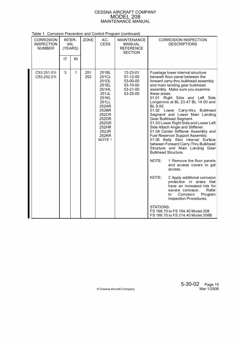
7/24/2019 CAB-11-5 R1
http://slidepdf.com/reader/full/cab-11-5-r1 301/345
CESSNA AIRCRAFT COMPANYMODEL 208
MAINTENANCE MANUAL
Table 1. Corrosion Prevention and Control Program (continued)
CORROSIONINSPECTION
NUMBER
INTER-VAL
(YEARS)
ZONE AC-CESS
MAINTENANCEMANUAL
REFERENCESECTION
CORROSION INSPECTIONDESCRIPTIONS
IT RI
C53.251.01IC53.252.01I
3 1 251252
251BL251CL251DL251EL251HL251JL251KL251LL252AR252BR
252CR252DR252GR252HR252JR252KR
NOTE 1
12-23-0151-12-0053-00-0053-10-0053-21-0053-25-00
Fuselage lower internal structurebeneath floor panel between theforward carry-thru bulkhead assemblyand main landing gear bulkheadassembly. Make sure you examinethese areas:01.01 Right Side and Left SideLongerons at BL 23.47 BL 14.00 andBL 9.00.01.02 Lower Carry-thru BulkheadSegment and Lower Main LandingGear Bulkhead Segment.01.03 Lower Right Side and Lower LeftSide Attach Angle and Stiffener.01.04 Center Stiffener Assembly andFuel Reservoir Support Assembly.01.05 Belly Skin Internal Surfacebetween Forward Carry-Thru BulkheadStructure and Main Landing Gear Bulkhead Structure.
NOTE: 1 Remove the floor panelsand access covers to getaccess.
NOTE: 2 Apply additional corrosionprotection in areas thathave an increased risk for severe corrosion. Refer to Corrosion ProgramInspection Procedures.
STATIONS:FS 168.70 to FS 194.40 Model 208FS 188.70 to FS 214.40 Model 208B
5-30-02 Page 15© Cessna Aircraft Company Mar 1/2008

7/24/2019 CAB-11-5 R1
http://slidepdf.com/reader/full/cab-11-5-r1 302/345
CESSNA AIRCRAFT COMPANYMODEL 208
MAINTENANCE MANUAL
Table 1. Corrosion Prevention and Control Program (continued)
CORROSIONINSPECTION
NUMBER
INTER-VAL
(YEARS)
ZONE AC-CESS
MAINTENANCEMANUAL
REFERENCESECTION
CORROSION INSPECTIONDESCRIPTIONS
IT RI
C53.251.02IC53.252.02I
3 1 251252
251FL251GL251NL251ML252ER252FR252LR252MR
NOTE 1
12-23-0151-12-0053-00-0053-10-0053-21-0053-25-00
Fuselage lower internal structurebeneath floor panel at the main landinggear bulkhead assembly. Make sureyou examine these areas:02.01 Longitudinal Bulkheads at BL0.0, BL 13.97 and BL 23.50.02.02 Lower Forward and Lower
Aft Main Landing Gear BulkheadSegments.02.03 Sealing Skin Internal Surface
Between Forward and Aft Main LandingGear Bulkhead.
NOTE: 1 Remove the floor panelsand access covers to getaccess.
NOTE: 2 Apply additional corrosionprotection in areas thathave an increased risk for severe corrosion. Refer to Corrosion ProgramInspection Procedures.
STATIONS:FS 194.40 to FS 208.00 Model 208FS 214.40 to FS 228.00 Model 208B
5-30-02 Page 16© Cessna Aircraft Company Mar 1/2008

7/24/2019 CAB-11-5 R1
http://slidepdf.com/reader/full/cab-11-5-r1 303/345
CESSNA AIRCRAFT COMPANYMODEL 208
MAINTENANCE MANUAL
Table 1. Corrosion Prevention and Control Program (continued)
CORROSIONINSPECTION
NUMBER
INTER-VAL
(YEARS)
ZONE AC-CESS
MAINTENANCEMANUAL
REFERENCESECTION
CORROSION INSPECTIONDESCRIPTIONS
IT RI
C53.251.03IC53.252.03I
3 1 251252
251BL251CL251DL251EL251FL251GL252AR252BR252CR252DR
252ER252FRNOTE 1
12-23-0153-00-0053-10-0053-21-0053-25-00
Fuselage lower internal structurebeneath floor panel forward of theforward carry-thru bulkhead assembly.Make sure you examine these areas:03.01 Longerons at BL 0.00, BL 13.97and BL 23.47.03.02 Lower Bulkhead Segments at FS166.45 and FS 175.95.03.03 Lower Skin Internal SurfaceBetween Bulkhead at FS 166.45 andForward Carry-Thru Bulkhead at FS186.45.03.04 Seat Tracks.
NOTE: 1 Remove the floor panelsand access covers to getaccess.
NOTE: 2 Apply additional corrosionprotection in areas thathave an increased risk for severe corrosion. Refer to Corrosion ProgramInspection Procedures.
STATIONS: FS 166.45 to FS 186.45.Model 208B Only
C53.253.01EC53.254.01E
3 1 253254
12-22-0153-00-0053-10-0053-23-00
Fuselage right side lower forward, leftside lower forward, right side lower center, left side lower center, lower forward, lower center skin and externaldoublers. Make sure you examinethese areas:01.01 Fuselage Right and Left SideLower Forward Skin Surface.01.02 Fuselage Right and Left SideLower Center Skin Surface.01.03 Fuselage Lower Forward Skinand Lower Center Skin Surface.01.04 Fuselage Right and Left SideDoublers.01.05 Right and Left Main LandingGear Bay Stiffener.STATIONS:FS 166.45 to FS 208.00 Model 208FS 166.45 to FS 228.00 Model 208B
5-30-02 Page 17© Cessna Aircraft Company Mar 1/2008

7/24/2019 CAB-11-5 R1
http://slidepdf.com/reader/full/cab-11-5-r1 304/345
CESSNA AIRCRAFT COMPANYMODEL 208
MAINTENANCE MANUAL
Table 1. Corrosion Prevention and Control Program (continued)
CORROSIONINSPECTION
NUMBER
INTER-VAL
(YEARS)
ZONE AC-CESS
MAINTENANCEMANUAL
REFERENCESECTION
CORROSION INSPECTIONDESCRIPTIONS
IT RI
C53.255.01EC53.256.01E
6 3 255256
12-22-0153-00-0053-10-0053-23-00
Fuselage upper aft, right side aftand left side aft skin. Make sure youexamine these areas:01.01 Fuselage Upper Aft Skin Surface.01.02 Fuselage Right Side Aft and LeftSide Aft Skin Surface.STATIONS:FS 208.00 to FS 322.80 Model 208FS 228.00 to FS 365.00 Model 208B
5-30-02 Page 18© Cessna Aircraft Company Mar 1/2008

7/24/2019 CAB-11-5 R1
http://slidepdf.com/reader/full/cab-11-5-r1 305/345
CESSNA AIRCRAFT COMPANYMODEL 208
MAINTENANCE MANUAL
Table 1. Corrosion Prevention and Control Program (continued)
CORROSIONINSPECTION
NUMBER
INTER-VAL
(YEARS)
ZONE AC-CESS
MAINTENANCEMANUAL
REFERENCESECTION
CORROSION INSPECTIONDESCRIPTIONS
IT RI
C53.255.01IC53.256.01I
3 1 255256
255AL255BL255CL255DL255EL255FL255GL255HL255JL255KL
255LL255ML255NL255PL255QL255RL255SL255TL255UL255VL255WL255XL255YL256AR
256BR256CR256DR256ER256FR256GR256HR256JR256KR256LR256MR256NR256PR256QR
256RR256SR256TR256UR256VR256WR256XR256YR
NOTE 1
12-23-0151-12-0053-00-0053-10-0053-21-0053-25-00
Fuselage lower internal structurebeneath the floor panel between aftmain landing gear bulkhead and aftcargo/passenger door jamb bulkhead.Make sure you examine these areas:01.01 Longerons at BL 0.0, BL 13.97and BL 23.47.01.02 Lower Right Side and Lower LeftSide Stiffener.01.03 Lower Bulkhead SegmentsBetween Aft Main Landing Gear Bulkhead and Aft Cargo/Passenger Door Jamb Bulkhead.01.04 Doublers at Longeron to Door Jamb Bulkhead Attach.01.05 Lower Skin Internal SurfaceBetween Aft Main Landing Gear Bulkhead and Aft Cargo/Passenger Door Jamb Bulkhead.01.06 Seat Tracks.
NOTE: 1 Remove floor panelsand access covers to getaccess.
NOTE: 2 Apply additional corrosionprotection in areas thathave an increased risk for severe corrosion. Refer to Corrosion ProgramInspection Procedures.
STATIONS:FS 208.00 to FS 284.00 Model 208FS 228.00 to FS 332.00 Model 208B
5-30-02 Page 19© Cessna Aircraft Company Mar 1/2008

7/24/2019 CAB-11-5 R1
http://slidepdf.com/reader/full/cab-11-5-r1 306/345
CESSNA AIRCRAFT COMPANYMODEL 208
MAINTENANCE MANUAL
Table 1. Corrosion Prevention and Control Program (continued)
CORROSIONINSPECTION
NUMBER
INTER-VAL
(YEARS)
ZONE AC-CESS
MAINTENANCEMANUAL
REFERENCESECTION
CORROSION INSPECTIONDESCRIPTIONS
IT RI
C53.255.02IC53.256.02I
3 1 255256
255QL255RL255SL255TL256QR256RR256SR256TR
255AAL255ZL
255ABL255ACL256AAR256ZR
256ABR256ACRNOTE 1
12-23-0151-12-0053-00-0053-10-0053-21-0053-25-00
Fuselage lower internal structurebeneath the floor panel between aftcargo/passenger door jamb bulkheadand curtain attach bulkhead. Makesure you examine these areas:02.01 Outboard, Inboard and Center Longerons.02.02 Lower Bulkhead SegmentsBetween Aft Cargo/Passenger Door Jamb Bulkhead and Curtain AttachBulkhead.02.03 Lower Skin Internal SurfaceBetween Aft Cargo/Passenger Door Jamb Bulkhead and Curtain AttachBulkhead.
NOTE: 1 Remove floor panelsand access covers to getaccess.
NOTE: 2 Apply additional corrosionprotection in areas thathave an increased risk for severe corrosion. Refer
to Corrosion ProgramInspection Procedures.
STATIONS:FS 284.00 to FS 308.00 Model 208FS 332.00 to FS 356.00 Model 208B
C53.257.01EC53.258.01E
6 3 257258
12-22-0153-00-0053-10-0053-23-00
Fuselage lower center aft and lower aftskin. Make sure you examine theseareas:01.01 Fuselage Lower Center Aft SkinSurface.01.02 Fuselage Lower Aft Skin Surface.STATIONS:FS 208.00 to FS 322.80 Model 208FS 228.00 to FS 365.00 Model 208B
5-30-02 Page 20© Cessna Aircraft Company Mar 1/2008

7/24/2019 CAB-11-5 R1
http://slidepdf.com/reader/full/cab-11-5-r1 307/345
CESSNA AIRCRAFT COMPANYMODEL 208
MAINTENANCE MANUAL
Table 1. Corrosion Prevention and Control Program (continued)
CORROSIONINSPECTION
NUMBER
INTER-VAL
(YEARS)
ZONE AC-CESS
MAINTENANCEMANUAL
REFERENCESECTION
CORROSION INSPECTIONDESCRIPTIONS
IT RI
C53.311.01EC53.312.01E
6 3 311312
12-22-0153-00-0053-10-0053-23-00
Tailcone upper, right side, left side,lower skin, and dorsal skin. Make sureyou examine these areas:01.01 Tailcone Upper and Lower SkinSurface.01.02 Tailcone Right Side and Left SideSkin Surface.01.03 Tailcone Dorsal Skin Surface.STATIONS:FS 322.00 to FS 388.68 Model 208
FS 365.00 to FS 436.68 Model 208BC53.311.01IC53.312.01I
3 1 311312
320A Tailcone forward canted bulkheadassembly. Make sure you examinethese areas:01.01 Elevator Bell Crank Bracket
Assembly including Bracket, Angles,Doublers and Stiffeners.01.02 Upper and Lower CantedBulkhead.01.03 Right and Left Stabilizer AttachFitting.STATIONS:FS 388.68 Model 208FS 436.68 Model 208B
C53.320.01E 6 3 320 12-22-0153-00-0053-10-0053-23-00
Tailcone right side aft, left side aft, andlower aft skin. Make sure you examinethese areas:01.01 Tailcone Right Side Aft and LeftSide Aft Skin Surface.01.02 Tailcone Lower Aft Skin Surface.STATIONS:FS 388.68 to FS 427.88 Model 208FS 436.68 to FS 475.88 Model 208B
C53.320.01I 3 1 320 330ANOTE
Tailcone aft canted bulkhead assembly.Make sure you examine these areas:01.01 Canted Bulkhead.01.02 Right Side and Left Side Doubler.01.03 Support Bracket and Stiffeners.01.04 Forward and Aft Stabilizer AttachFitting.
NOTE: Remove stinger to getaccess.
STATIONS:FS 427.88 Model 208FS 475.88 Model 208B
5-30-02 Page 21© Cessna Aircraft Company Mar 1/2008

7/24/2019 CAB-11-5 R1
http://slidepdf.com/reader/full/cab-11-5-r1 308/345
CESSNA AIRCRAFT COMPANYMODEL 208
MAINTENANCE MANUAL
Table 1. Corrosion Prevention and Control Program (continued)
CORROSIONINSPECTION
NUMBER
INTER-VAL
(YEARS)
ZONE AC-CESS
MAINTENANCEMANUAL
REFERENCESECTION
CORROSION INSPECTIONDESCRIPTIONS
IT RI
C55.320.01E 3 1 320 330A 55-00-0055-30-00
Vertical stabilizer forward spar andrear spar attachment. Make sure youexamine these areas:01.01 Vertical Stabilizer Forward andRear Spar Attach Bolt.01.02 Vertical Stabilizer Forward andRear Spar around Bolt AttachmentSTATIONS:WL 134.38; BL 3.18 Upper AttachWL 126.03; BL 3.44 Lower Attach
Models 208 and 208BC55.340.01E 5 2 340 55-00-00
55-10-0155-30-00
Vertical stabilizer leading edge skinand fairing. Make sure you examinethese areas:01.01 Vertical Stabilizer Leading EdgeSkin Surface.01.02 Vertical Stabilizer Fairing SkinSurface around Screw Attachment.STATIONS:WL 135.50 to WL 207.50 VerticalStabilizer Leading Edge Models 208and 208BFS 322.80 to FS 404.60 Fairing Model208
FS 365.00 to FS 452.60 Fairing Model208B
C55.341.01E 3 1 341 55-00-0055-30-00
Vertical stabilizer upper and lower skin.Make sure you examine these areas:01.01 Vertical Stabilizer Upper andLower Skin Surface.01.02 Access Cover around Screw
Attachment.STATIONS:WL 135.50 to WL 207.50 Models 208and 208B
C55.343.01E 5 2 343 55-00-0055-30-0055-40-00
Rudder left side and right side skin.Make sure you examine these areas:01.01 Rudder Skin Surface.01.02 Access Cover around Screw
Attachment.STATIONS: WL 135.50 to WL 225.50Models 208 and 208B
5-30-02 Page 22© Cessna Aircraft Company Mar 1/2008

7/24/2019 CAB-11-5 R1
http://slidepdf.com/reader/full/cab-11-5-r1 309/345
CESSNA AIRCRAFT COMPANYMODEL 208
MAINTENANCE MANUAL
Table 1. Corrosion Prevention and Control Program (continued)
CORROSIONINSPECTION
NUMBER
INTER-VAL
(YEARS)
ZONE AC-CESS
MAINTENANCEMANUAL
REFERENCESECTION
CORROSION INSPECTIONDESCRIPTIONS
IT RI
C55.343.01I 3 1 343 55-00-0055-30-0055-40-00
Rudder upper, center, and lower hingeattachment. Make sure you examinethese areas:01.01 Rudder Upper, Center and Lower Hinge Bearing Plate.01.02 Rudder Upper, Center and Lower Hinge Bearing.
NOTE: Do not apply LPS-3 Heavy-Duty Rust Inhibitor on
bearings.
STATIONS:WL 206.28; BL 00.00 Upper Hinge LineWL 161.78; BL 00.00 Center Hinge LineWL 125.00; BL 00.00 Lower Hinge LineModels 208 and 208B
C55.343.02E 3 1 343 55-00-0055-30-0055-40-00
Rudder upper, center, and lower hinges. Make sure you examine theseareas:02.01 Rudder Upper, Center and Lower Hinge Attach Bolt.02.02 Rudder Upper, Center and Lower Hinge Bracket.
STATIONS:WL 206.28; BL 00.00 Upper Hinge LineWL 161.78; BL 00.00 Center Hinge LineWL 125.00; BL 00.00 Lower Hinge LineModels 208 and 208B
C55.343.03E 1 1 343 55-00-0055-30-0055-40-00
Rudder torque tube assembly. Makesure you examine these areas:03.01 Rudder Torque Tube aroundWelded Joint at Support Plate andFrame.03.02 Rudder Torque Tube around BellCrank Welded Joint.03.03 Rudder Torque Tube Inner
Surface at Bell Crank Welded Joint.STATIONS: WL 124.31 to WL 142.88Models 208 and 208B
5-30-02 Page 23© Cessna Aircraft Company Mar 1/2008

7/24/2019 CAB-11-5 R1
http://slidepdf.com/reader/full/cab-11-5-r1 310/345
CESSNA AIRCRAFT COMPANYMODEL 208
MAINTENANCE MANUAL
Table 1. Corrosion Prevention and Control Program (continued)
CORROSIONINSPECTION
NUMBER
INTER-VAL
(YEARS)
ZONE AC-CESS
MAINTENANCEMANUAL
REFERENCESECTION
CORROSION INSPECTIONDESCRIPTIONS
IT RI
C55.343.04E 1 1 343 55-00-0055-30-0055-40-00
Rudder Torque Tube bell crank. Makesure you examine these areas:04.01 Rudder Torque Tube Bell CrankSurface around Welded Joint.04.02 Rudder Torque Tube Bell CrankStop Block.STATIONS: WL 124.31 Models 208 and208B
C55.371.01EC55.372.01E
5 2 371372
55-00-0055-10-00
55-10-01
Horizontal stabilizer leading edge skinbetween SS 11.50 and SS 114.00.
Make sure you examine this area:01.01 Horizontal Stabilizer LeadingEdge Skin Surface.STATIONS: SS 11.50 to SS 114.00Models 208 and 208B
C55.373.01EC55.374.01E
3 1 373374
55-00-0055-10-00
Horizontal stabilizer upper and lower skin. Make sure you examine theseareas:01.01 Horizontal Stabilizer Upper andLower Skin Surface.01.02 Access Cover around Screw
Attachment.STATIONS: SS 0.00 to SS 114.00
Models 208 and 208BC55.373.02EC55.374.02E
3 1 373374
330ANOTE
55-00-0055-10-00
Horizontal stabilizer forward spar andrear spar attachment. Make sure youexamine these areas:02.01 Horizontal Stabilizer ForwardSpar Attach Fitting and Attach Bolt.02.02 Horizontal Stabilizer Rear Spar
Attach Support and Attach Bolt
NOTE: Remove horizontal stabilizer upper and lower fairing,forward and aft inspectioncovers to get access.
STATIONS:SS 8.50 Forward AttachmentSS 5.75 Aft AttachmentModels 208 and 208B
5-30-02 Page 24© Cessna Aircraft Company Mar 1/2008

7/24/2019 CAB-11-5 R1
http://slidepdf.com/reader/full/cab-11-5-r1 311/345
CESSNA AIRCRAFT COMPANYMODEL 208
MAINTENANCE MANUAL
Table 1. Corrosion Prevention and Control Program (continued)
CORROSIONINSPECTION
NUMBER
INTER-VAL
(YEARS)
ZONE AC-CESS
MAINTENANCEMANUAL
REFERENCESECTION
CORROSION INSPECTIONDESCRIPTIONS
IT RI
C55.375.01EC55.376.01E
5 2 375376
55-00-0055-10-0055-20-00
Elevator skin and elevator leadingedge skin. Make sure you examinethese areas:01.01 Elevator Upper and Lower SkinSurface.01.02 Elevator Leading Edge SkinSurface.STATIONS: SS 8.00 to SS 123.00Models 208 and 208B
C55.375.01I
C55.376.01I
3 1 375
376
330A 55-00-00
55-10-0055-20-00
Elevator inboard, center, and outboard
hinges. Make sure you examine theseareas:01.01 Elevator Inboard, Center andOutboard Hinge Support.01.02 Elevator Inboard, Center, andOutboard Bearing Plate.01.03 Elevator Inboard, Center, andOutboard Hinge Bearing.
NOTE: Do not apply LPS-3 Heavy-Duty Rust Inhibitor onbearings.
STATIONS:
SS 0.00 - Center Elevator HingeSS 55.00 - Inboard Elevator HingeSS 114.00 - Outboard Elevator HingeModels 208 and 208B
C55.375.02EC55.376.02E
3 1 375376
330A 55-00-0055-10-0055-20-00
Elevator torque tube. Make sure youexamine these areas:02.01 Elevator Torque Tube Surface.02.02 Elevator Torque Tube End Plateand Adapter Plate.02.03 Elevator Torque Tube End Plateto Adapter Plate Attach Bolt.STATIONS: SS 0.00 to SS 22.00Models 208 and 208B
5-30-02 Page 25© Cessna Aircraft Company Mar 1/2008

7/24/2019 CAB-11-5 R1
http://slidepdf.com/reader/full/cab-11-5-r1 312/345
CESSNA AIRCRAFT COMPANYMODEL 208
MAINTENANCE MANUAL
Table 1. Corrosion Prevention and Control Program (continued)
CORROSIONINSPECTION
NUMBER
INTER-VAL
(YEARS)
ZONE AC-CESS
MAINTENANCEMANUAL
REFERENCESECTION
CORROSION INSPECTIONDESCRIPTIONS
IT RI
C56.240.01E 3 1 240 56-00-0056-00-01
Windshield Installation. Make sure youexamine this area:01.01 Windshield Retainers andRetainer Screws.
NOTE: Do not apply LPS-3 Heavy-Duty Rust Inhibitor onwindshield.
STATIONS: FS 100.00 to FS 143.00
Models 208 and 208BC56.251.01EC56.252.01E
6 3 251252255256
56-00-0056-00-0156-20-00
Passenger Window Installation. Makesure you examine this area:01.01 Passenger Window Retainersand Retainer Screws.
NOTE: Do not apply LPS-3 Heavy-Duty Rust Inhibitor onwindow.
STATIONS: FS 100.00 to FS 143.00Models 208 and 208B
C56.801.01E
C56.802.01E
6 3 801
802
56-00-00
56-00-0156-30-00
Crew Window Installation. Make sure
you examine this area:01.01 Crew Window Retainers andRetainer Screws.
NOTE: Do not apply LPS-3 Heavy-Duty Rust Inhibitor onwindow.
STATIONS: FS 100.00 to FS 143.00Models 208 and 208B
C56.803.01EC56.804.01E
6 3 803804
56-00-0056-00-0156-30-00
Cargo Door Window Installation. Makesure you examine this area:01.01 Cargo Door Window Retainersand Retainer Screws.
NOTE: Do not apply LPS-3 Heavy-Duty Rust Inhibitor onwindow.
STATIONS: FS 100.00 to FS 143.00Models 208 and 208B
5-30-02 Page 26© Cessna Aircraft Company Mar 1/2008

7/24/2019 CAB-11-5 R1
http://slidepdf.com/reader/full/cab-11-5-r1 313/345
CESSNA AIRCRAFT COMPANYMODEL 208
MAINTENANCE MANUAL
Table 1. Corrosion Prevention and Control Program (continued)
CORROSIONINSPECTION
NUMBER
INTER-VAL
(YEARS)
ZONE AC-CESS
MAINTENANCEMANUAL
REFERENCESECTION
CORROSION INSPECTIONDESCRIPTIONS
IT RI
C57.501.01EC57.601.01E
4 2 501601
57-00-0057-10-0057-40-00
Wing leading edge skin between WS35.0 and WS 155.9. Make sure youexamine these areas:01.01 Wing Leading Edge SkinSurface.01.02 Access Cover around Screw
Attachment.STATIONS: WS 35.00 to WS 155.90Models 208 and 208B
C57.501.01I
C57.601.01I
3 1 501
601
501AB
501BB501CB501DB501EB601AB601BB601CB601DB601EB
NOTE 1
30-00-00
30-10-0057-00-0057-10-0057-40-00
Wing deice boot at leading edge
between WS 35.00 and WS 155.90.Make sure you examine this area:01.01 Wing Leading Edge Areas Under Deice Boot.
NOTE: 1 Remove deice boot toget access if corrosion issuspected.
NOTE: 2 Apply this basic task if there is an indication of corrosion under deice boot.
STATIONS: WS 35.00 to WS 155.90
Models 208 and 208B
C57.503.01EC57.603.01E
3 1 503603
57-00-0057-10-0057-40-00
Wing leading edge skin between WS155.9 and WS 308.0. Make sure youexamine these areas:01.01 Wing Leading Edge SkinSurface.01.02 Access Cover around Screw
Attachment.STATIONS: WS 155.90 to WS 308.00Models 208 and 208B
5-30-02 Page 27© Cessna Aircraft Company Mar 1/2008

7/24/2019 CAB-11-5 R1
http://slidepdf.com/reader/full/cab-11-5-r1 314/345
CESSNA AIRCRAFT COMPANYMODEL 208
MAINTENANCE MANUAL
Table 1. Corrosion Prevention and Control Program (continued)
CORROSIONINSPECTION
NUMBER
INTER-VAL
(YEARS)
ZONE AC-CESS
MAINTENANCEMANUAL
REFERENCESECTION
CORROSION INSPECTIONDESCRIPTIONS
IT RI
C57.503.01IC57.603.01I
3 1 503603
503AB503BB503CB503DB503EB503FB503GB503HB503JB603AB
603BB603CB603DB603EB603FB603GB603HB603JB
NOTE 1
30-00-0030-10-0057-00-0057-10-0057-40-00
Wing deice boot at leading edgebetween WS 155.90 to WS 308.00.Make sure you examine this area:01.01 Wing Leading Edge Areas Under Deice Boot.
NOTE: 1 Remove deice boot toget access if corrosion issuspected.
NOTE: 2 Apply this basic task if there is an indication of corrosion under deice boot.
STATIONS: WS 155.90 to WS 308.00Models 208 and 208B
C57.521.01EC57.621.01E
3 1 521621
57-00-0057-10-0057-11-00
Wing upper and lower forward skinbetween WS 53.0 and WS 214.3.Make sure you examine these areas:01.01 Wing Skin Surface.01.02 Access Cover around Screw
Attachment.STATIONS: WS 53.00 to WS 214.30Models 208 and 208B
C57.521.01IC57.621.01I
3 1 521621
511AB611AB
NOTE 2
57-00-0057-10-00
Wing forward and rear spar fitting luginner bore. Make sure you examinethese areas:01.01 Forward Spar Fitting LugSurface.01.02 Rear Spar Fitting Lug Surface
NOTE: 1 If corrosion is foundon the lug surface, or if the attaching hardware
(bolt, nut, or cotter pin) iscorroded, remove the attachbolt and inspect the lug bore.
NOTE: 2 Remove wing to fuselagefairing to get access.
STATIONS: WS 35.00 Models 208 and208B
5-30-02 Page 28© Cessna Aircraft Company Mar 1/2008

7/24/2019 CAB-11-5 R1
http://slidepdf.com/reader/full/cab-11-5-r1 315/345
CESSNA AIRCRAFT COMPANYMODEL 208
MAINTENANCE MANUAL
Table 1. Corrosion Prevention and Control Program (continued)
CORROSIONINSPECTION
NUMBER
INTER-VAL
(YEARS)
ZONE AC-CESS
MAINTENANCEMANUAL
REFERENCESECTION
CORROSION INSPECTIONDESCRIPTIONS
IT RI
C57.521.02EC57.621.02E
3 1 521621
511AB611ABNOTE
57-00-0057-10-00
Wing forward and rear spar fitting andfitting attachment. Make sure youexamine these areas:02.01 Forward Spar Attach Fitting andFitting Attach Bolt.02.02 Rear Spar Attach Fitting andFitting Attach Bolt
NOTE: Remove wing to fuselagefairing to get access.
STATIONS: WS 35.00 Models 208 and208B
C57.523.01EC57.623.01E
3 1 523623
57-00-0057-10-0057-11-00
Wing upper and lower forward skinbetween WS 214.3 and WS 308.0.Make sure you examine these areas:01.01 Wing Skin Surface.01.02 Access Cover Around Screw
Attachment.STATIONS: WS 214.30 to WS 308.00Models 208 and 208B
C57.525.01EC57.625.01E
3 1 525625
57-00-0057-10-00
57-11-00
Wing upper and lower aft skin betweenWS 35.0 and WS 229.0. Make sure
you examine these areas:01.01 Wing Skin Surface.01.02 Access Cover around Screw
Attachment.STATIONS: WS 35.00 to WS 229.00Models 208 and 208B
C57.527.01EC57.627.01E
5 2 527627
57-00-0057-10-0057-50-00
Flap skin and flap leading edge skinbetween WS 35.0 and WS 228.0.Make sure you examine these areas:01.01 Flap Skin Surface.01.02 Flap Leading Edge Skin Surface.STATIONS: WS 35.00 to WS 228.00Models 208 and 208B
5-30-02 Page 29© Cessna Aircraft Company Mar 1/2008

7/24/2019 CAB-11-5 R1
http://slidepdf.com/reader/full/cab-11-5-r1 316/345
CESSNA AIRCRAFT COMPANYMODEL 208
MAINTENANCE MANUAL
Table 1. Corrosion Prevention and Control Program (continued)
CORROSIONINSPECTION
NUMBER
INTER-VAL
(YEARS)
ZONE AC-CESS
MAINTENANCEMANUAL
REFERENCESECTION
CORROSION INSPECTIONDESCRIPTIONS
IT RI
C57.527.01IC57.627.01I
1 1 527627
57-00-0057-10-0057-50-00
Flap track sliding mechanismattachment. Make sure you examinethese areas:01.01 Inboard and Center Flap TrackForward Roller and Bushing.01.02 Inboard and Center Flap Track
Aft Bearing.
NOTE: Do not apply LPS-3 Heavy-Duty Rust Inhibitor on
bearings.
STATION:WS 53.00 Inboard Flap TrackWS 126.50 Center Flap TrackModels 208 and 208B
C57.527.02EC57.627.02E
1 1 527627
57-00-0057-10-0057-50-00
Flap track structure including inboard,center and outboard flap tracks. Makesure you examine these areas:02.01 Inboard, Center and OutboardFlap Track.02.02 Inboard, Center and OutboardFlap Support Attach Bolt.02.03 Inboard and Center Flap Bracket
and Attach Bolt.STATION:WS 53.00 Inboard Flap TrackWS 126.50 Center Flap TrackWS 214.30 Outboard Flap TrackModels 208 and 208B
C57.527.03EC57.627.03E
3 1 527627
57-00-0057-70-00
Spoiler inboard, center, and outboardhinges. Make sure you examine theseareas:03.01 Spoiler Inboard, Center andOutboard Hinge Half.03.02 Spoiler Inboard, Center andOutboard Hinge Pin.
NOTE: Do not apply LPS-3 Heavy-Duty Rust Inhibitor on hingepin.
STATION:WS 170.90 Inboard Spoiler HingeWS 199.80 Center Spoiler HingeWS 228.50 Outboard Spoiler HingeModels 208 and 208B
5-30-02 Page 30© Cessna Aircraft Company Mar 1/2008

7/24/2019 CAB-11-5 R1
http://slidepdf.com/reader/full/cab-11-5-r1 317/345
CESSNA AIRCRAFT COMPANYMODEL 208
MAINTENANCE MANUAL
Table 1. Corrosion Prevention and Control Program (continued)
CORROSIONINSPECTION
NUMBER
INTER-VAL
(YEARS)
ZONE AC-CESS
MAINTENANCEMANUAL
REFERENCESECTION
CORROSION INSPECTIONDESCRIPTIONS
IT RI
C57.531.01EC57.631.01E
1 1 531631
521CB621CB
NOTE 2
57-00-0057-10-0057-10-01
Wing strut upper and lower attachfitting lug, wing strut to lower fuselageattach fitting lug, and wing strut towing attach fitting lug. Make sure youexamine these areas:01.01 Wing Strut Upper and Lower
Attach Fitting Lug Surface.01.02 Wing Strut to Lower Fuselage
Attach Fitting Lug Surface.01.03 Wing Strut to Wing Attach Fitting
Lug Surface.
NOTE: 1 If corrosion is found on thelug surface or if the attachinghardware (bolt, nut, or cotter pin) is corroded, remove theattach bolt and inspect thelug bore.
NOTE: 2 Remove the wing strutcuffs to get access.
STATION:FS 168.70 Model 208
FS 188.70 Model 208B
5-30-02 Page 31© Cessna Aircraft Company Mar 1/2008

7/24/2019 CAB-11-5 R1
http://slidepdf.com/reader/full/cab-11-5-r1 318/345
CESSNA AIRCRAFT COMPANYMODEL 208
MAINTENANCE MANUAL
Table 1. Corrosion Prevention and Control Program (continued)
CORROSIONINSPECTION
NUMBER
INTER-VAL
(YEARS)
ZONE AC-CESS
MAINTENANCEMANUAL
REFERENCESECTION
CORROSION INSPECTIONDESCRIPTIONS
IT RI
C57.531.01IC57.631.01I
1 1 531631
521CB621CB
NOTE 2
57-00-0057-10-0057-10-01
Wing strut upper and lower attachfitting lug, wing strut to lower fuselageattach fitting lug, and wing strut towing attach fitting lug. Make sure youexamine these areas:01.01 Wing Strut Upper and Lower
Attach Fitting Lug Surface.01.02 Wing Strut to Lower Fuselage
Attach Fitting Lug Surface.01.03 Wing Strut to Wing Attach Fitting
Lug Surface.
NOTE: 1 If corrosion is found on thelug surface or if the attachinghardware (bolt, nut, or cotter pin) is corroded, remove theattach bolt and inspect thelug bore.
NOTE: 2 Remove the wing strutcuffs to get access.
STATION:FS 168.70 Model 208
FS 188.70 Model 208BC57.531.02EC57.631.02E
1 1 531631
521CB621CB
NOTE 2
57-00-0057-10-0057-10-01
Wing strut to lower fuselage attachmentand wing strut to wing attachment.Make sure you examine these areas:02.01 Wing Strut to Lower Fuselage
Attach Fitting Lug Bore Surface at Bolt Attachment.02.02 Wing Strut to Wing Attach FittingLug Bore Surface at Bolt Attachment.
NOTE: 1 If corrosion is found on thelug surface or if the attachinghardware (bolt, nut, or cotter pin) is corroded, remove theattach bolt and inspect thelug bore.
NOTE: 2 Remove the wing strutcuffs and strut fairing to getaccess.
STATION:FS 168.70 Model 208FS 188.70 Model 208B
5-30-02 Page 32© Cessna Aircraft Company Mar 1/2008

7/24/2019 CAB-11-5 R1
http://slidepdf.com/reader/full/cab-11-5-r1 319/345
CESSNA AIRCRAFT COMPANYMODEL 208
MAINTENANCE MANUAL
Table 1. Corrosion Prevention and Control Program (continued)
CORROSIONINSPECTION
NUMBER
INTER-VAL
(YEARS)
ZONE AC-CESS
MAINTENANCEMANUAL
REFERENCESECTION
CORROSION INSPECTIONDESCRIPTIONS
IT RI
C57.531.03EC57.631.03E
5 2 531631
57-00-0057-10-0057-10-01
Wing strut fairing assembly. Make sureyou examine these areas:03.01 Wing Strut Fairing Surface.03.02 Upper and Lower Strut Cuff SkinSurface.STATION:FS 168.70 Models 208FS 188.70 Models 208B
C57.551.01EC57.651.01E
3 1 551651
57-00-0057-10-00
57-11-00
Wing upper and lower aft skin betweenWS 229.0 to WS 308.0. Make sure you
examine these areas:01.01 Wing Skin Surface.01.02 Access Cover around Screw
Attachment.STATIONS: WS 229.00 to WS 308.00Models 208 and 208B
C57.571.01EC57.671.01E
5 2 571671
57-00-0057-10-0057-60-00
Aileron skin, aileron leading edge skinand aileron trim tab skin between WS228.50 and WS 308.00. Make sureyou examine these areas:01.01 Aileron Skin Surface01.02 Aileron Leading Edge SkinSurface.
01.03 Aileron Trim Tab Skin Surface.STATIONS: WS 228.50 to WS 308.0Models 208 and 208B
C57.571.01IC57.671.01I
3 1 571671
57-00-0057-60-00
Aileron inboard and outboard hinges.Make sure you examine these areas:01.01 Aileron Inboard and OutboardHinge Bearing.01.02 Aileron Inboard and OutboardHinge Support.
NOTE: Do not apply LPS-3 Heavy-Duty Rust Inhibitor onbearings.
STATIONS:WS 229.66 Inboard Aileron HingeWS 304.22 Outboard Aileron HingeModels 208 and 208B
5-30-02 Page 33© Cessna Aircraft Company Mar 1/2008

7/24/2019 CAB-11-5 R1
http://slidepdf.com/reader/full/cab-11-5-r1 320/345
CESSNA AIRCRAFT COMPANYMODEL 208
MAINTENANCE MANUAL
Table 1. Corrosion Prevention and Control Program (continued)
CORROSIONINSPECTION
NUMBER
INTER-VAL
(YEARS)
ZONE AC-CESS
MAINTENANCEMANUAL
REFERENCESECTION
CORROSION INSPECTIONDESCRIPTIONS
IT RI
C57.571.02EC57.671.02E
3 1 571671
57-00-0057-10-0057-60-00
Aileron trim tab hinge. Make sure youexamine these areas:02.01 Aileron Trim Tab Hinge Half.02.02 Aileron Trim Tab Hinge Pin.
NOTE: Do not apply LPS-3 Heavy-Duty Rust Inhibitor on hingepin
STATIONS: WS 276.24 to WS 308.00
Models 208 and 208BC61.110.01E 3 1 110 12-21-04
61-00-0061-10-0061-11-00
Engine propeller and propeller dome.Make sure you examine this area:01.01 Propeller Blade Surface andPropeller Dome Surface.STATIONS: FS 31.50 Models 208 and208B
5-30-02 Page 34© Cessna Aircraft Company Mar 1/2008

7/24/2019 CAB-11-5 R1
http://slidepdf.com/reader/full/cab-11-5-r1 321/345
CESSNA AIRCRAFT COMPANYMODEL 208
MAINTENANCE MANUAL
Table 1. Corrosion Prevention and Control Program (continued)
CORROSIONINSPECTION
NUMBER
INTER-VAL
(YEARS)
ZONE AC-CESS
MAINTENANCEMANUAL
REFERENCESECTION
CORROSION INSPECTIONDESCRIPTIONS
IT RI
C61.110.01I 3 1 110 NOTE 1 12-21-0461-00-0061-10-0061-11-0061-40-00
Propeller and spinner installation,beta indicating system, and propeller overspeed governor installation. Makesure you examine these areas:01.01 Low Stop Collar, Spinner Bulkhead, Spinner Bulkhead Supportand Spinner Attach Bolts (Refer toNOTE 2).01.02 Feedback Collar, Spinner Support, Spinner Mounting Plate,
Spinner Bulkhead and Spinner AttachBolts (Refer to NOTE 2).01.03 Beta Indicating Installationincluding Beta Switch, Plunger,Bracket, Attach Plate, Spring and
Attach Screws.01.04 Propeller Governor Linkage.
NOTE: 1 Remove the propeller dome and nose cap to getaccess.
NOTE: 2 Corrosion InspectionNumber 01.01 applies
to airplanes with Hartzelpropeller installation.Corrosion InspectionNumber 01.02 applies toairplanes with McCauleypropeller installation.
STATIONS: FS 31.50 Models 208 and208B
C71.121.01EC71.122.01E
8 4 121122
71-10-00 Engine cowl door skin. Make sure youexamine these areas:01.01 Engine Cowl Center SectionSurface.01.02 Engine Upper Cowl Right andLeft Door Surfaces.STATIONS: FS 49.47 to FS 100.00Models 208 and 208B
5-30-02 Page 35© Cessna Aircraft Company Mar 1/2008

7/24/2019 CAB-11-5 R1
http://slidepdf.com/reader/full/cab-11-5-r1 322/345
CESSNA AIRCRAFT COMPANYMODEL 208
MAINTENANCE MANUAL
Table 1. Corrosion Prevention and Control Program (continued)
CORROSIONINSPECTION
NUMBER
INTER-VAL
(YEARS)
ZONE AC-CESS
MAINTENANCEMANUAL
REFERENCESECTION
CORROSION INSPECTIONDESCRIPTIONS
IT RI
C71.121.02EC71.122.02E
2 2 121122
71-10-00 Engine cowl door upper attachstructure. Make sure you examinethese areas:02.01 Forward Hinge Support, AftHinge Support and Attach Screws.02.02 Upper Cowl Door Hinge, HingeBearing and Hinge Attach Bolts.
NOTE: Do not apply LPS-3 Heavy-Duty Rust Inhibitor on the
bearings.
STATIONS:FS 58.30 Forward Cowl AttachFS 95.35 Aft Cowl AttachModels 208 and 208B
C71.121.03EC71.122.03E
4 2 121122
71-10-00 Engine cowl side door latch structure.Make sure you examine these areas:03.01 Right and Left Side Forward,Center and Aft Latch Brackets.03.02 Latch Hook, Bolt, Spacer andNut.STATIONS:FS 45.00 Forward Cowl Door Latch
FS 40.00 Center Cowl Door LatchFS 95.25 Aft Cowl Door LatchModels 208 and 208B
C71.121.04EC71.122.04E
8 4 121122
71-10-00 Engine nose cap and cowl bulkheadinstallation. Make sure you examinethis area:04.01 Engine Nose Cap Surface andCowl Bulkhead Surface.STATION: FS 31.50 Models 208 and208B
5-30-02 Page 36© Cessna Aircraft Company Mar 1/2008

7/24/2019 CAB-11-5 R1
http://slidepdf.com/reader/full/cab-11-5-r1 323/345
CESSNA AIRCRAFT COMPANYMODEL 208
MAINTENANCE MANUAL
Table 1. Corrosion Prevention and Control Program (continued)
CORROSIONINSPECTION
NUMBER
INTER-VAL
(YEARS)
ZONE AC-CESS
MAINTENANCEMANUAL
REFERENCESECTION
CORROSION INSPECTIONDESCRIPTIONS
IT RI
C71.130.01I 2 1 130 NOTE 71-20-00 Engine truss assemblies. Make sureyou examine these areas:01.01 Engine Truss Tube Surface.01.02 Areas around Engine TrussJunction Weld.01.03 Right and Left Side Landing Gear Junctions.01.04 Engine Truss to Firewall AttachBolts.01.05 ETM Instrument Box Attach
Location at Right Side of Lower TrussTube.01.06 Ignition Exciter Box AttachLocation at Right Side of Truss Tube.
NOTE: Remove the engine cowldoor to get access.
STATION: FS 61.78 to FS 100.00Models 208 and 208B
5-30-02 Page 37© Cessna Aircraft Company Mar 1/2008

7/24/2019 CAB-11-5 R1
http://slidepdf.com/reader/full/cab-11-5-r1 324/345
CESSNA AIRCRAFT COMPANYMODEL 208
MAINTENANCE MANUAL
Table 1. Corrosion Prevention and Control Program (continued)
CORROSIONINSPECTION
NUMBER
INTER-VAL
(YEARS)
ZONE AC-CESS
MAINTENANCEMANUAL
REFERENCESECTION
CORROSION INSPECTIONDESCRIPTIONS
IT RI
C71.130.02I 2 1 130 NOTE 71-20-00 Engine mount assemblies. Make sureyou examine these areas:02.01 Engine Upper, Right and LeftSide Mount Brackets.02.02 Engine Mount and Mount Bolts.02.03 Engine Mount to Engine Ring
Attach Bolts.
NOTE: Remove the engine cowldoor to get access.
STATION: FS 61.78 Models 208 and208B
C71.130.03I 2 1 130 NOTE 71-20-00 Engine ring assembly. Make sure youexamine these areas:03.01 Engine Ring Surface.03.02 Areas Around Junction Weld.03.03 Engine Ring to Engine Truss
Attach Bolts.
NOTE: Remove the engine cowldoor and nose cap to getaccess.
STATION: FS 61.78 Models 208 and208B
C78.130.01E 2 1 130 NOTE 78-00-0078-10-00
Exhaust system installation. Makesure you examine these areas:01.01 Primary Exhaust Duct, and
Attach Bolts.01.02 Secondary Exhaust Duct, and
Attach Screws.01.03 Exhaust Deflector and Retainer Screws.01.04 Inboard, Center and OutboardSecondary Exhaust Hanger Brackets.
NOTE: Remove the right side lower engine cowl to get access tosecondary exhaust.
STATION: FS 49.47 to FS 100.00Models 208 and 208B
5-30-02 Page 38© Cessna Aircraft Company Mar 1/2008

7/24/2019 CAB-11-5 R1
http://slidepdf.com/reader/full/cab-11-5-r1 325/345
CESSNA AIRCRAFT COMPANYMODEL 208
MAINTENANCE MANUAL
CORROSION PREVENTION AND CONTROL PROGRAM - APPENDIX
1. A pp en dix A - Development Of The Baseline Program
A. The Corrosion Prevention and Control Program Baseline Program.(1) The function of the Corrosion Prevention and Control Program (CPCP) is to give the minimum
procedures necessary to prevent and control corrosion so that continued airworthiness is notrisked. The Principle Structural Elements (PSEs) are areas where the CPCP applies.
(2) The CPCP Baseline Program consists of a Corrosion Program Inspection (CPI), ImplementationThreshold (IT), and a Repeat Interval (RI). Each inspection is to be done in an airplane zone.
(3) The corrosion reports that are sent to Cessna Aircraft Company and data from the FAA ServiceDifficulty Records from 1995 to 2002 were used to identify the inspection areas of the BaselineProgram. When more than one incident of corrosion was identified at a specified location, aninspection was included for that location in the Baseline Program.
(4) When corrosion was found once, the data was examined to find if the corrosion was caused byone specified occurrence or if other airplanes could have corrosion in the same location. If so,this inspection was added to the Baseline Program.
(5) The inspection interval was specified by the duration and corrosion severity.
2. Appendix B - Procedures For Recording Inspection Results
A. Record the Inspection Results.(1) It is not an FAA mandatory procedure to record the CPCP results, but Cessna Aircraft
Company recommends that records be kept to assist in program adjustments when necessary.The inspection of records will make sure the identification, repeat, and level of corrosion ismonitored. The data can identify whether there is more or less corrosion at repeat intervals.The data can also be used to approve increased or decreased inspection intervals.
3. A pp en di x C - Guidelines
A. Glossary(1) The following additional information clarifies the previous sections of this document.
B. The Glossary of General Descriptions. Refer to Table 1, Figure 1, Figure 2, Figure 3, and Figure 4.
WORD GENERAL DESCRIPTION
Allowable Limit The allowable limit is the maximum amount of material (usually expressed inmaterial thickness) that may be removed or blended out without affecting theultimate design strength capability of the structural member. Allowable limitsmay be established by the design approval holder. The FAA (or applicableregulatory authority) may also establish allowable limits. The design approvalholder normally publishes allowable limits in the structural repair manual or inservice bulletins.
Baseline Pr ogram A Baseline Program is a CPCP developed for a specific model airplane.The design approval holder typically develops the Baseline Program.However, it may be developed by a group of operators who intend to use it indeveloping their individual CPCP. It contains the corrosion program inspection,an implementation threshold, and a repeat interval for the procedure
accomplishment in each area or zone.
Basic Task Refer to corrosion program inspection.
Corrosion ProgramInspection (CPI)
The corrosion program inspection (CPI) is a specific and fundamental setof work elements that should be performed repetitively in all task areas or zones to successfully control corrosion. The contents of the CPI may varydepending upon the specific requirements in an airplane area or zone. TheCPI is developed to protect the primary structure of the airplane.
5-30-05 Page 1© Cessna Aircraft Company Mar 1/2008

7/24/2019 CAB-11-5 R1
http://slidepdf.com/reader/full/cab-11-5-r1 326/345
CESSNA AIRCRAFT COMPANYMODEL 208
MAINTENANCE MANUAL
WORD GENERAL DESCRIPTION
Corrosion (Metal) The physical deterioration of metals caused by reaction to an adverseenvironment.
Corrosion Prevention and
Control Program (CPCP)
A Corrosion Prevention and Control Program is a comprehensive and
systematic approach to controlling corrosion such that the load carryingcapability of an airplane structure is not degraded below a level necessaryto maintain airworthiness. It contains the corrosion program inspections, adefinition of corrosion levels, implementation thresholds, a repeat intervalfor task accomplishment in each area or zone, and specific procedures if corrosion damage exceeds Level 1 in any area or zone.
Design Approval Holder The design approval holder is either the type certificate holder for the aircraftor the supplemental type certificate holder.
Implementation Threshold(IT)
The implementation threshold for a specific airplane is the date, based onthat airplane’s age, by which the initial corrosion inspection task should beaccomplished in an area or zone.
Inspection Area The inspection area is a region of airplane structure to which one or more CPIs
are assigned. The inspection area may also be referred to as a Zone.Level 1 Corrosion Level 1 Corrosion is one or more of the items that follow:
1. Corrosion damage occurring between successive inspections, that islocal and can be reworked or blended out with the allowable limit.
2. Local corrosion damage that exceeds the allowable limit but can beattributed to an event not typical of the operator’s usage or other airplanes in the same fleet (e.g., mercury spill).
3. Operator experience has demonstrated only light corrosion betweeneach successive corrosion task inspection; the latest corrosioninspection task results in rework or blend out that exceeds the allowablelimit.
Level 2 Corrosion Level 2 corrosion occurs between two successive corrosion inspection tasksthat requires a single rework or blend-out that exceeds the allowable limit.
A finding of Level 2 corrosion requires repair, reinforcement or complete or partial replacement of the applicable structure.
Level 3 Corrosion Level 3 corrosion occurs during the first or subsequent accomplishmentsof a corrosion inspection task that the operator determines to be an urgentairworthiness concern.
NOTE: If Level 3 corrosion is determined at the implementation threshold or any repeat inspection, it should be reported. Any corrosion that ismore than the maximum acceptable to the design approval holder or the FAA (or applicable regulatory authority) must be reported inaccordance with current regulations. This determination should beconducted jointly with the design approval holder.
Light Corrosion Light corrosion is corrosion damage so slight that removal and blendout over
multiple repeat intervals (RI) may be accomplished before material lossexceeds the allowable limit.
Local Corrosion Generally, local corrosion is corrosion of a skin or web (wing, fuselage,empennage, or strut) that does not exceed one frame, stringer, or stiffener bay. Local corrosion is typically limited to a single frame, chord, stringer, or stiffener, or the corrosion of more than one frame, chord, stringer, or stiffener where no corrosion exists on two adjacent members on each side of thecorroded member.
5-30-05 Page 2© Cessna Aircraft Company Mar 1/2008

7/24/2019 CAB-11-5 R1
http://slidepdf.com/reader/full/cab-11-5-r1 327/345
CESSNA AIRCRAFT COMPANYMODEL 208
MAINTENANCE MANUAL
WORD GENERAL DESCRIPTION
Principal StructuralElement (PSE)
A PSE is an element that contributes significantly to carrying flight, ground or pressurization loads, and whose integrity is essential in maintaining the overallstructural integrity of the airplane.
Repeat Interval (RI) The repeat interval is the calendar time between the accomplishment of successive corrosion inspection tasks for a Task Area or Zone.
Task Area Refer to Inspection Area.
Urgent AirworthinessConcern
An urgent airworthiness concern is damage that could jeopardize continuedsafe operation of any airplane. An urgent airworthiness concern typicallyrequires cor rection before the next flight and expeditious action to inspect theother airplanes in the operator’s fleet.
Widespread Corrosion Widespread corrosion is corrosion of two or more adjacent skin or web bays (aweb bay is defined by frame, stringer, or stiffener spacing). Or, widespreadcorrosion is corrosion of two or more adjacent frames, chords, stringers, or stiffeners. Or, widespread corrosion is corrosion of a frame, chord, stringer, or stiffener and an adjacent skin or web bay.
Zone Refer to Inspection Area.
4. Application Of The Corrosion Program Inspection
NOTE: In this manual the Basic Tasks are referred to as the Corrosion Program Inspection (CPI).
A. Typical Airplane Zone Corrosion Program Inspection Procedures.(1) Remove all the equipment and airplane interior (for example the insulation, upper upholstery
panel, lower upholstery panel) as necessary to do the corrosion inspection.(2) Clean the areas given in the corrosion inspection before you inspect them.(3) Do a visual inspection of all of the Principal Structural Elements (PSEs) and other structure given
in the corr osion inspection for corrosion, cracking, and deformation.(a) Carefully examine the areas that show that corrosion has occurred before.
NOTE: Areas that need a careful inspection are given in the corrosion inspection.
(b) Nondestructive testing inspections or visual inspections can be needed after somedisassembly if the inspection shows a bulge in the skin, corrosion under the splices or corrosion under fittings.
(4) Remove all of the corrosion, examine the damage, and repair or replace the damaged structure.(a) Apply a protective finish where it is required. Refer to Chapter 20, Interior and Exterior
Finish - Cleaning/Painting or Chapter 51, Corrosion - Description and Operation.(b) Clean or replace the ferrous metal fasteners with oxidation.
(5) Remove blockages of foreign object debris so that the holes and clearances between parts candrain.
(6) For bare metal on any surface of the airplane, apply fuel and corrosion resistant primer MIL-PRF-23377.(a) Apply a polyurethane topcoat paint to the exterior painted surface. Refer to the
manufacturer's procedures.(7) Cessna Air craft Company recommends that you apply a corrosion preventive compound once
every two years to areas with a high possibility for severe corrosion identified in the corrosioninspection.(a) On the Model 208, apply LPS-3 Heavy-Duty Rust Inhibitor, or equivalent, in the bilge area
below the floorboards between FS 168.00 and FS 211.00. Refer to Chapter 51, Corrosion- Description and Operation.
(b) On the Model 208B, apply LPS-3 Heavy-Duty Rust Inhibitor, or equivalent, in the bilge areabelow the floorboards between FS 168.00 and FS 356.00. Refer to Chapter 51, Corrosion- Description and Operation
5-30-05 Page 3© Cessna Aircraft Company Mar 1/2008

7/24/2019 CAB-11-5 R1
http://slidepdf.com/reader/full/cab-11-5-r1 328/345

7/24/2019 CAB-11-5 R1
http://slidepdf.com/reader/full/cab-11-5-r1 329/345

7/24/2019 CAB-11-5 R1
http://slidepdf.com/reader/full/cab-11-5-r1 330/345

7/24/2019 CAB-11-5 R1
http://slidepdf.com/reader/full/cab-11-5-r1 331/345

7/24/2019 CAB-11-5 R1
http://slidepdf.com/reader/full/cab-11-5-r1 332/345
CESSNA AIRCRAFT COMPANYMODEL 208
MAINTENANCE MANUAL
(8) Apply compounds that will replace water and prevent corrosion. Refer to Chapter 51, Corrosion- Description and Operation.(a) Apply one layer of LPS-3 Heavy-Duty Rust Inhibitor, or equivalent, that will soak into the
fayed surfaces to replace water and prevent corrosion.
Table 1. Areas and Items Not to Apply Compounds to Replace Water and Prevent Corrosion
AREA or ITEM
Oxygen System Lines and Components
Cables, Pulleys, and Trim Tab Pushrod
Plastics, Elastomers
Lubricated and Teflon Surfaces (Greased Joints, Sealed Bearings, and Grommets)
Adjacent to Tears and Holes in Insulation (Not Waterproof)
Areas with Electrical Arc Potential, Wiring
Interior Upholstery Panels (Changes the Flammability Properties)
Cargo Pod (Changes the Flammability Properties)
Pitot Tubes
Fuel Cap
Tie Down Lugs
Chrome Items (handles, locks)
Standard Polished Spinner
Stall Warning Detector
(9) Install the dry insulation blankets.(10) Install the equipment and airplane interior (upper upholstery panel, lower upholstery panel) that
was removed to do the corrosion inspection.
5. Determination of the Corrosion Levels
A. Find the Cor rosion Levels (Refer to Figure 5).(1) Corrosion found on a structure when you use the Corrosion Program and Corrosion Prevention
(CPCP) Baseline Program will help find the extent of the corrosion.(2) The second and subsequent inspections will find how well the CPCP program has been
prepared, or if there is a need to make adjustments to the Baseline Program.(3) A good quality CPCP is one that controls corrosion to Level 1 or better.(4) If Level2 corrosion is found during the second or subsequent inspection, you must do something
to decrease the future corrosion to Level 1 or better.(5) If Level 3 corrosion is found, you must also do something to decrease the future corrosion to
Level 1. Also, a plan to find or prevent Level 3 corrosion in the same area on other airplanesmust be added to the CPCP.
(6) All the corrosion that you can repair in the allowable damage limits, found in the Model 208Structural Repair Manual, is Level 1 corrosion.
(7) If all corrosion is Level 1, the CPCP is correctly prepared.(8) If you must reinforce or replace the part because of corrosion, the corrosion is Level 2.(9) If the part is not airworthy because of the corrosion, you must do an analysis to find out if the
corrosion is Level 3.(10) The chart found in this section will help find the level of the corrosion.(11) The probability that the same problem will occur on another airplane is dependent on several
factors such as: past maintenance history, operating environment, years in service, inspectabilityof the corroded area and the cause of the problem.
5-30-05 Page 8© Cessna Aircraft Company Mar 1/2008

7/24/2019 CAB-11-5 R1
http://slidepdf.com/reader/full/cab-11-5-r1 333/345

7/24/2019 CAB-11-5 R1
http://slidepdf.com/reader/full/cab-11-5-r1 334/345

7/24/2019 CAB-11-5 R1
http://slidepdf.com/reader/full/cab-11-5-r1 335/345

7/24/2019 CAB-11-5 R1
http://slidepdf.com/reader/full/cab-11-5-r1 336/345
CESSNA AIRCRAFT COMPANYMODEL 208
MAINTENANCE MANUAL
B. Level 2 Corrosion Findings.(1) All Level 2 corrosion that is more than the rework limits of the Structural Repair Manual must be
reported to Cessna Aircraft Company. Cessna Aircraft Company engineering will do an analysisto make sure the corrosion is not a urgent airworthiness concern.
(2) When doing the analysis, Cessna Aircraft Company will consider:(a) Can the cause of the corrosion be identified, such as a chemical spill or protective finish
breakdown?(b) Has the same level of corrosion been found on other airplanes?(c) Are the corrosion protection procedures applied during manufacture the same for earlier
and later models?(d) Age of the corroded airplane compared to others checked.(e) Is the maintenance history different than the other airplanes in the fleet?
6. Typical Actions That Follow the Determination of the Corrosion Level.
A. If corrosion is found, find the corrosion level, then do the necessary steps for a specific inspection.
B. If Level 1 corrosion is found during the first CPCP inspection.(1) Repair the structure. Refer to the Model 208 Structural Repair Manual or a Cessna Aircraft
Company approved repair procedure.
(2) Continue with the Baseline Program.(a) Optional: Document the results of the inspection for use in validating program compliance.
C. If Level 2 corrosion is found during the first CPCP inspection.(1) Repair the structure. Refer to the Model 208 Structural Repair Manual or Cessna Aircraft
Company approved repair procedure.(2) Report the details of the corrosion you see to Cessna Aircraft Company and the FAA (or
applicable regulatory authority).(3) Continue to use the Baseline Program but check the corroded area carefully when you do a
subsequent CPCP inspection.(4) It is recommended that you record the results of the inspection to show compliance with the
program.
D. If Level 3 corrosion is found during the first CPCP inspection.(1) Immediately contact Cessna Aircraft Company and the FAA or regulatory authority of the
corrosion you found. Refer to Reporting System.(2) Give sufficient information to make sure that the condition is a possible urgent airworthiness
concern for your fleet. Get assistance from Cessna Propeller Aircraft Product Support to developa plan of action.
(3) Apply the corrosion program inspection, which includes the repair of the structure. Refer to theModel 208 Structural Repair Manual or a Cessna Aircraft Company approved repair procedure.
(4) Do a report that has the information of the findings. Refer to Corrosion Prevention And ControlProgram Reporting System - Description And Operation.
(5) Continue with the Baseline Program and other steps of procedure required by the FAA, or applicable regulatory authority. Examine this area carefully during future inspections.
E. If no corrosion is found during the second or subsequent CPCP inspection:(1) Continue with the current Corrosion Prevention and Control Program. No adjustment of the
current program is required.(2) It is recommended that you record the results of the inspection for a possible increase of the
corrosion inspection Implementation Threshold (IT) and/or Repeat Interval (RI).
F. If Level 1 corrosion is found on the second or subsequent CPCP inspection:(1) Do the corrosion program inspection, which includes the repair of the structure. Refer to the
Model 208 Structural Repair Manual or a Cessna Aircraft Company approved repair procedure.(2) Continue with the Baseline Program.(3) No adjustment of the existing program is required.(4) It is recommended that you record the corrosion inspection number and the results of the
inspection to show that the program was obeyed.
5-30-05 Page 12© Cessna Aircraft Company Mar 1/2008

7/24/2019 CAB-11-5 R1
http://slidepdf.com/reader/full/cab-11-5-r1 337/345
CESSNA AIRCRAFT COMPANYMODEL 208
MAINTENANCE MANUAL
G. If Level 2 corrosion is found on the second or subsequent CPCP inspection:(1) Repair the structure. Refer to the Model 208 Structural Repair Manual or a Cessna Aircraft
Company approved repair procedure.(2) Do a report that shows the information about the corrosion and send it to Cessna Aircraft
Company and the FAA (or applicable regulatory authority).(3) If corrosion damage required the removal of material just beyond the allowable limits (within 10
percent), complete a check of the other airplanes in the fleet before you change the maintenanceprogram.(a) If the corrosion is typical of Level 2, use the fleet data to find what changes are required to
control corrosion to Level 1 or better.(b) If fleet damage is typically Level 1, examine the corroded area during subsequent
inspections on all affected airplanes.(c) Make changes to the maintenance program if the typical corrosion becomes Level 2.
(4) Further evaluation by Cessna Aircraft Company is recommended for Level 2 corrosion findingsthat are well beyond the allowable limits, and there is an airworthiness concern in which promptaction is required.
NOTE: The airworthiness concern is because of the possibility to have similar but moresevere corrosion on any other airplane in the operator's fleet prior to the next
scheduled inspection of that area.
(5) Find the action required to control the corrosion to a Level 1 or better, between future successiveinspections. These can include the items that follow:(a) A structural modification, such as additional drainage.(b) Improvements to the corrosion prevention and control inspections, such as more care and
attention to corrosion removal, reapplication of protective finish, drainage path clearance.(c) Decrease the Implementation Threshold (IT) for additional airplanes that go into the
program.(d) Decrease the Repeat Interval (RI).
(6) Send a plan of corrective action to the FAA or applicable regulatory authority for approval andto Cessna Aircraft Company.
(7) Use the approved plan of action.
H. If Level 3 corr osion is found on the second or subsequent CPCP inspection:
(1) contact Cessna Aircraft Company and the FAA (or applicable regulatory authority) about thecorrosion that was found.
(2) Send a plan to examine the same area on other affected airplanes in the operator's fleet.
NOTE: Circumstances can dictate the need to examine airplanes younger than thecorresponding Baseline Program Implementation Threshold.
(3) Apply the corrosion program inspection, which includes the repair of the structure. Use theModel 208 Str uctural Repair Manual or a Cessna Aircraft Company approved repair procedure.
I. Find the action needed to control the corrosion finding to Level 1 or better, between future successiveinspections. These can include any or all of the following:(1) A structural modification, such as additional drainage.(2) Improvements to the corrosion prevention and control inspections, such as more care and
attention to corrosion removal, reapplication of protective finish, drainage path clearance.(3) A decrease in the Implementation Threshold (IT) for additional airplanes entering the program.(4) A decrease in the Repeat Interval (RI).
J. Send a plan of corrective action to the FAA (or applicable regulator authority for approval) as needed.
K. Use the approved plan of action.
L. It is recommended that you give the details of the findings to Cessna Aircraft Company.
5-30-05 Page 13© Cessna Aircraft Company Mar 1/2008

7/24/2019 CAB-11-5 R1
http://slidepdf.com/reader/full/cab-11-5-r1 338/345
CESSNA AIRCRAFT COMPANYMODEL 208
MAINTENANCE MANUAL
7. Factors Influencing Corrosion Occurrences
A. If you find Level 2 or Level 3 corrosion, when you think about how to change your CPCP, think aboutthe list that follows:(1) Is there a presence of LPS-3 Heavy-Duty Rust Inhibitor?
(2) Is there a presence or condition of protective finish?(3) What was the Implementation Threshold (IT) of the operator's Corrosion Control and ControlProgram (CPCP)?
(4) What was the length of time since the last inspection and/or application of corrosion inhibitingcompound Repeat Interval (RI)?
(5) Was there inadequate clean-up/removal of corrosion prior to application of corrosion inhibitingcompound, during previous maintenance of the area?
(6) Are the moisture drains blocked or is there inadequate drainage?(7) What was the environment, the time of exposure to the environment and the use of the airplane?
(a) Was the environment tropical, desert, salt water or industrial?(b) Are there electrolytes or water and moisture, salt water or battery fluid?
(8) Was there a variation in past maintenance history and or use of the airplanes in the operator'sfleet?
(9) Were there variations in the production build standard in the operator's fleet?
8. Rep or ti ng
A. The minimum requirements to prevent or control the corrosion in the Corrosion Prevention and ControlProgram (CPCP) were made on the best information, knowledge and experience available at the time.
As this experience and knowledge get better, the CPCPs will be changed at intervals as necessary. A reporting system for this is in Section 4.0.(1) You must contact the Cessna Aircraft Company about all Level 2 or 3 corrosion of the structure
that is on the list in the Baseline Program that is found during the second and subsequentcorrosion program inspections. Refer to Reporting System.
NOTE: You do not have to contact the Cessna Aircraft Company about corrosion that is foundon structure that is not on the list in the Baseline Program, for example the secondarystructure.
9. Program Implementation
A. When a CPCP is started it is important to do the items that follow:(1) Start inspections where the airplane age is equal to or greater than the Baseline Program
Implementation Threshold age (IT).(2) Once the corrosion program inspection (CPI) is started, the subsequent applications of the CPI
are given by the Repeat Interval (RI) for each CPI.(3) You can start a CPCP on the basis of individual CPIs or groups of CPIs.(4) Cessna Aircraft Company highly recommends to start all of the CPIs as soon as possible. This
is the most cost effective way to prevent or control corrosion.
5-30-05 Page 14© Cessna Aircraft Company Mar 1/2008

7/24/2019 CAB-11-5 R1
http://slidepdf.com/reader/full/cab-11-5-r1 339/345
CESSNA AIRCRAFT COMPANYMODEL 208
MAINTENANCE MANUAL
UNSCHEDULED MAINTENANCE CHECKS
1. Gen er al
A. During operation, the airplane may be subjected to:(1) Hard landings.
(2) Overspeed.(3) Severe air turbulence or severe maneuvers.(4) Towing with a large fuel unbalance or high drag/side loads due to ground handling.(5) Lightning Strike.
B. When any of these conditions are reported by the flight crew, a visual inspection of the airframe andspecific inspections of components and areas involved must be accomplished.
C. The inspections are performed to determine and evaluate the extent of damage in local areas of visibledamage, and to the structure and components adjacent to the area of damage.
D. If foreign object damage is encountered (suspected or actual), a visual inspection of the airplane mustbe accomplished before airplane is returned to service.
2. Unscheduled Maintenance Checks Defined and Areas to be Inspected
A. Hard/Overweight Landings.(1) A hard landing is any landing made at what is believed to be an excessive sink rate. Closely
related to hard landings, is an overweight landing, which is defined as landing the airplane at anygross weight which exceeds maximum gross landing weight as specified in the FAA ApprovedPilot's Operating Handbook and FAA Approved Airplane Flight Manual.
NOTE: If the hard/overweight landing is combined with high drag/side loads, additionalchecks are required.
(2) Hard or overweight landing check.(a) Landing gear.
1 Main gear struts - Inspect for security of attachment and permanent set.2 Main gear attachments and supporting structure - Inspect for security, loose or failed
fasteners, and any evidence of structural damage.3 Main gear spring - Inspect for gear spread or wing low.4 Nose gear trunnion supports and attaching structure - Inspect for security, loose or
failed fasteners, and any evidence of structural damage.5 Nose gear attachments and supporting structure - Inspect for security, loose or failed
fasteners, and any evidence of structural damage.(b) Wings.
1 Wing surface and lift strut - Inspect for skin buckles, loose or failed fasteners, andsecurity of attach fittings and fuel leaks
2 Trailing edge - Inspect for any deformation affecting normal flap operation.
B. Overspeed.(1) Any time an airplane has exceeded one or both of the following:
(a) Airplane overspeed exceeding placard speed limits of flaps.(b) Airplane overspeed exceeding design speeds.
(2) Airplanes equipped with an airspeed exceedance device capable of recording an airspeedexceedence with accompanying time duration:(a) For a recorded airspeed above 175 knots in smooth air, with duration greater than 5
seconds; or any airspeed above 181 knots, perform the specified overspeed inspection.(3) Overspeed (airspeed) check.
(a) Fuselage.1 Windshield and Windows - Inspect for buckling, dents, loose or failed fasteners, and
any evidence of structural damage.2 All hinged doors - Inspect hinges, hinge attach points, latches and attachments, and
skins for defor mation and evidence of structural damage.
5-50-00 Page 1© Cessna Aircraft Company Apr 1/2010

7/24/2019 CAB-11-5 R1
http://slidepdf.com/reader/full/cab-11-5-r1 340/345
CESSNA AIRCRAFT COMPANYMODEL 208
MAINTENANCE MANUAL
(b) Cowling.1 Skins - Inspect for buckling, cracks, loose or failed fasteners, and indications of
structural damage.(c) Stabilizers.
1 Stabilizers - Inspect skins, hinges and attachments, movable surfaces, mass balanceweights, and attaching structure for cracks, dents, buckling, loose or failed fasteners,and evidence of structural damage.
(d) Wings.1 Flaps - Inspect for skin buckling, cracks, loose or failed fasteners, attachments and
structure for damage.2 Fillets and fairings - Inspect for buckling, dents, cracks, and loose or failed fasteners.
C. Severe air turbulence or severe maneuvers.(1) May be defined as atmospheric conditions producing violent buffeting of airplane. Severe
maneuvers can be defined as any maneuvers exceeding Pilot's Operating Handbook and FAA Approved Airplane Flight Manual limits.
(2) Severe turbulence and/or maneuvers checks.(a) Stabilizers.
1 Horizontal stabilizer hinge fittings, actuator fittings and stabilizer center section -Inspect for security, loose or failed fasteners, and any evidence of structural damage.
2 Vertical stabilizer - Inspect for evidence of structural damage, skin buckles andsecurity at pr imary attachments in tailcone, loose or failed fasteners, damage tohinges and actuator fittings.
3 Elevator and rudder balance weight supporting structure - Inspect for security, looseor failed fasteners, and evidence of structural damage.
(b) Wing.1 Wing to body strut fittings and supporting structure - Inspect for security, loose or
failed fasteners, and evidence of structural damage.2 Trailing Edge - Inspect for any deformation affecting normal operation of flap and
aileron.
D. Lightning strike.(1) If flown through an electrically stressed region of the atmosphere where electrical discharges
are transferred from cloud to cloud and from cloud to earth, the airplane may become a part of
this discharge path. During a lightning strike, the current enters the airplane at one point andexits at another, usually at opposite extremities. The wing tips, nose and tail sections are theareas where damage is most likely to occur. Burning and/or eroding of small surface areas of theskin and structure may be detected during inspection. In most cases, the damage is obvious. Insome cases, however, hidden damage may result. The purpose of the lightning strike inspectionis to locate any damage that may have occurred to the airplane before returning it to service.
(2) Lightning strike check.(a) As the following checks are performed, complete Lightning Strike/Static Discharge Incident
Reporting Form. Completed form must be mailed to Cessna Contract Services, P.O. Box7706, Wichita, KS 67277 Attn: Manager Contract Services.
(b) Communications.1 Antennas - Inspect all antennas for evidence of burning or eroding. If damage is
noted, perform functional check of affected system.(c) Navigation.
1 Radar reflector, feed horn, motor box assembly and mounting structure. Inspect for damage. If damage is noted, perform a bench check of system. If superficial pitting or burning of mount structure only is noted, perform a functional check of radar system.
2 Glideslope antenna - Inspect for burning and pitting. If damage is noted, perform afunctional check of glideslope system.
3 Compass - Compass should be considered serviceable if the corrected heading iswithin plus or minus 10 degrees of heading indicated by the remote compass system.If remote compass is not within tolerance, remove, repair or replace.
(d) Fuselage.1 Skin - Inspect surface of fuselage skin for evidence of damage.2 Tailcone - Inspect tailcone and static dischargers for damage.
5-50-00 Page 2© Cessna Aircraft Company Apr 1/2010

7/24/2019 CAB-11-5 R1
http://slidepdf.com/reader/full/cab-11-5-r1 341/345
CESSNA AIRCRAFT COMPANYMODEL 208
MAINTENANCE MANUAL
(e) Stabilizers.1 Inspect surfaces of stabilizers for evidence of damage.
(f) Wings.1 Skins - Inspect for evidence of burning and eroding.2 Wing tips - Inspect for evidence of burning and pitting.3 Flight surfaces and hinging mechanisms - Inspect for burning and pitting.4 Radome - Inspect for evidence of burning or eroding.
(g) Propeller.1 Propeller - Remove from service and have inspected at an authorized repair station.
(h) Powerplant1 Refer to the engine manufacturer's maintenance manual, unscheduled inspection.
E. Foreign object damage.(1) Damage to the airplane engine may be caused by the ingestion of slush, by a bird strike or by
any other foreign object while operating the airplane on the ground or in normal flight. Damagemay also be caused by tools, bolts, nuts, washers, rivets, rags or pieces of safety-wire left inthe engine inlet duct during maintenance operations. The purpose of the foreign object damageinspection is to locate any damage prior to repairing or returning the airplane to service.
(2) Safety precautions should be taken to prevent foreign objects from coming in contact with theairplane during towing and at all times when airplane is not in service. To prevent dirt and foreign
objects damage, the engines should be provided with suitable covers. When there is wind anddust conditions, the covers should be installed as soon as practicable following engine shutdownand engine cooling.
(3) The aerodynamic cleanliness level (degree of surface smoothness), contributes to performancecapabilities of the airplane. It is important that the high cleanliness level be maintained.
(4) Contour and waviness distortion of the aerodynamic surface may be developed in the courseof normal operation or by improper handling during maintenance operations. Doors and accesspanels are susceptible to waviness through rough handling. Care should be exercised in thehandling of these items.
(5) Foreign object damage check.(a) Landing gear.
1 Fairings - Inspect for dents, cracks, misalignment, and indication of structuraldamage.
(b) Fuselage.
1 Skin - Inspect forward and belly areas for dents, punctures, cracks, and any evidenceof damage.
(c) Cowling.1 Skins - Inspect for dents, punctures, loose or failed fasteners, cracks or indications
of structural damage.(d) Stabilizers.
1 Leading edge skins - Inspect for dents, cracks, scratches, and any evidence of structural damage.
2 Surface de-ice boots - Inspect for cuts, punctures, or tears.(e) Windows.
1 Windshield - Inspect for chipping, scratches, and cracks.(f) Wings.
1 Leading edge skins - Inspect for dents, cracks, punctures, and evidence of possiblestructural damage.
2 Radome - Inspect for dents, cracks, punctures, scratches, etc.3 Surface de-ice boots - Inspect for cuts, punctures, or tears.
(g) Engine.1 Air inlet section - Inspect for dents, cracks, scratches, punctures, blood and feathers.2 Propeller - Inspect for nicked, bent, broken, cracked, or rubbing blades.
5-50-00 Page 3© Cessna Aircraft Company Apr 1/2010

7/24/2019 CAB-11-5 R1
http://slidepdf.com/reader/full/cab-11-5-r1 342/345
CESSNA AIRCRAFT COMPANYMODEL 208
MAINTENANCE MANUAL
F. High drag/side loads due to ground handling.(1) High drag/side load condition shall be defined to exist whenever the airplane skids or overruns
from the prepar ed surface onto an unprepared surface, or landings short of prepared surface,or makes a landing which involves the blowing of tires or skids on a runway to the extent thatthe safety of the airplane was in question. This covers takeoff and landings or unusual taxiconditions.
(2) High drag/side loads due to ground handling check.(a) Landing gear.
1 Main gear and f airings - Inspect for loose or failed fasteners, buckling, security,cracks, and evidence of structural damage.
2 Nose gear and fairing - Inspect for loose or failed fasteners, cracks, steering cablestension, security, buckling, and evidence of structural damage.
(b) Wings.1 Wing to fuselage attach fittings and attaching structure - Inspect for security, loose or
failed fasteners, and evidence of structural failure.
5-50-00 Page 4© Cessna Aircraft Company Apr 1/2010

7/24/2019 CAB-11-5 R1
http://slidepdf.com/reader/full/cab-11-5-r1 343/345

7/24/2019 CAB-11-5 R1
http://slidepdf.com/reader/full/cab-11-5-r1 344/345

7/24/2019 CAB-11-5 R1
http://slidepdf.com/reader/full/cab-11-5-r1 345/345
Owner Advisory
May 16, 2014 CAB11-5A
Dear Cessna Caravan Owner:
This Owner Advisory is to inform you that CAB11-5 Revision 1 Time Limits/Maintenance Checks - New208/208B Task-Based Inspection Program has been issued.
PURPOSE
The purpose of this Service Bulletin is to clarify the instructions provided in CAB11-5 Original Issue toincorporate the new, task-based inspection program on the Model 208/208B presented in Revision 24 to themaintenance manual. The task-based inspection program replaced the inspection program from Revision 23of the maintenance manual and the phase card inspections. The maintenance manual has since revised toRevision 27.
U.S. registered airplanes operating under CFR 14 Part 91 that have not obtained approval for the task-basedmaintenance program as a progressive inspection under 91.409 paragraph d or that have not obtained anexemption from CFR 14 Part 91.409(a) and (b) must be inspected as required by 91.409(a) and (b).
The task-based inspection program was incorporated on the Model 208/208B in order to make maintenanceprocedures and inspections more efficient for operators who obtain approval for the task-based inspectionprogram as an approved aircraft inspection program AAIP under part 135 of the U.S. aviation regulations or for operators who adopt the task-based program as a manufacturer’s recommended program as authorized by their local regulatory authorities. Cessna has reviewed all item codes for efficiency, applicability, and effectiveness.
• Many item codes were incorporated into one task.
• Item codes that were found to be not applicable or not effective were eliminated.
• Many item code intervals were extended within the new tasks.
• The scheduled maintenance checks in Chapter 5-20-01 were removed from the maintenance manual.
• Chapter 5-10-00 has incorporated inspection documents to replace the progressive care program and theinspection operations.
• Inspection time limits in Chapter 5-10-01 have tasks incorporated.
• Phase cards will no longer be sold, revised, or supported by Cessna Aircraft Company.
• The supplemental inspection documents (SIDS) were incorporated into the tasks. Refer to Chapter 5-14-00 for the conversion matrix.
• The CPCPs were incorporated into the tasks and incorporated into the task-based program.
COMPLIANCE
Optional: Conversion to the manufacturer’s recommended 208/208B Task-Based Inspection Program may beaccomplished at the owner's discretion with prior approval from your local regulatory authority.
NOTE: Compliance with CAB11-5 Revision 1 is required for airplanes that were able to comply with theOriginal Issue.
Page 1 of 2
To obtain satisfactory results, procedures specified in this publication must be accomplished in accordance with accepted methods andprevailing government regulations. Cessna Aircraft Company cannot be responsible for the quality of work performed in accomplishing therequirements of this publication.
Cessna Aircraft Company Customer Service P O Box 7706 Wichita Kansas 67277 U S A (316) 517-5800 Facsimile (316) 517-7271