ca62 user’s manual - english operation with led62 … with led62 keypad and pr62 proximity cards...
TRANSCRIPT

CA62 User’s Manual - Operation with LED62 Keypad and PR62 Proximity Cards Reader
English
2 CA62 Control Panel - User’s Manual
Contents
LED62 General Description 4 General Description 4 LED Indication 5 Keypad Sounder 7 Buttons 7
LED62 Keypad Operations 8 ARMING of Partition А 8 “Full ARM” Mode of Partition A 8 “Stay ARM” Mode of Partition A 8 “Instant ARM” Mode of Partition A 9 ARMING of Partition В 10
ARMING Both Partition А and Partition В 10 DISARMING of Partition А, Partition В or Both Partitions 10 Stopping the alarm 11 Panic Buttons 11 Ambush Code 11 Technical troubles review 11
User Programming Menu 12 Changing own user code 12 Memory LOG review from User 12 Chime Enabling / Disabling from User 12 Zone Bypassing from User 13
Manager Programming Menu 14 Changing user rights for remote access 14 Enabling / Disabling the Engineer Code Access 15 Sending of “Comm. Manual test” message 15 UDL Access Block 15 Changing of User Codes 16 Changing of User Rights 16 Changing of Manager Codes 16 Changing of Manager Rights 17 Memory LOG review from Manager 17 Chime Enabling / Disabling from Manager 18 Zone Bypassing from Manager 18 Setting the Clock 18 Setting the Date 18 Adding a Proximity Card 18 Deleting a Proximity Card 18
PR62 Proximity Card Reader Description 19 General Description 19 LED Indication 19 Sound Signalization 19 ARMING with a Proximity card 19 DISARMING with a Proximity card 19
System Checklist 20
SUPPLEMENTS 21
CA62 Control Panel - User’s Manual 3
General InformationGuarantee
During the guarantee period the manufacturer shall, at its sole discretion, replace or repair any defective product when it is returned to the factory. All parts replaced and/or repaired shall be covered for the remainder of the original guarantee, or for ninety (90) days, whichever period is longer. The original purchaser shall immediately send manufacturer a written notice of the defective parts or workmanship, which written notice must in all cases be received prior to expiry of the guarantee.
International GuaranteeForeign customers shall enjoy the same guarantee rights as those enjoyed by any customer in Bulgaria, except that manu-facturer shall not be liable for any related customs duties, taxes or VAT, which may be payable.Guarantee ProcedureThis guarantee will be granted when the appliance in question is returned. The manufacturer shall accept no product whatsoever, of which no prior notice has been received.Conditions for waiving the guaranteeThis guarantee shall apply to defects in products resulting only from improper materials or workmanship, related to its normal use. It shall not cover:• Damages resulting from transportation and handling;• Damages caused by natural calamities, such as fire, floods, storms, earthquakes or lightning;• Damages caused by incorrect voltage, accidental breakage or water; beyond the control of the manufacturer;• Damages caused by unauthorized system incorporation, changes, modifications or surrounding objects:• Damages caused by peripheral appliances (unless such peripheral appliances have been supplied by the manufac-turer:• Defects caused by inappropriate surrounding of installed products;• Damages caused by failure to use the product for its normal purpose; • Damages caused by improper maintenance;• Damages resulting from any other cause, bad maintenance or product misuse.In the case of a reasonable number of unsuccessful attempts to repair the product, covered by this guarantee, the manu-facturer’s liability shall be limited to the replacement of the product as the sole compensation for breach of the guarantee. Under no circumstances shall the manufacturer be liable for any special, accidental or consequential damages, on the grounds of breach of guarantee, breach of agreement, negligence, or any other legal notion.
WaiverThis Guarantee shall contain the entire guarantee and shall be prevailing over any and all other guarantees, explicit or implicit (including any implicit guarantees on behalf of the dealer, or adaptability to specific purposes), and over any other responsibilities or liabilities on behalf of the manufacturer. The manufacturer does neither agree, nor empower, any person, acting on his own behalf, to modify or alter this Guarantee, nor to replace it with another guarantee, or another liability with regard to this product. Unwarranted ServicesThe manufacturer shall repair or replace unwarranted products, which have been returned to its factory, at its sole discre-tion under the conditions below. The manufacturer shall accept no products for which no prior notice has been received.
• The products, which the manufacturer deems repairable, will be repaired and returned. • The manufacturer has prepared a price list and those products, which can be repaired, shall be paid for every repaired appliance.• The closest equivalent product, available at the time, shall replace the products manufacturer deems irreparable. The current market price shall be charged for every replaced product.
WarningsBefore using the LED62 Keypad, please ensure that you have read and understood the following instructions. Always ensure that the LED62 Keypad is operated correctly.Do not attempt to disassemble or alter any part of the equipment that is not expressly described in this guide. Internal inspections, alterations and repairs should be conducted by qualified service personnel only.Do not use substances containing alcohol, benzene, thinners or other flammable substances to clean or maintain the equipment. The use of these substances may lead to fire.Do not allow liquids to enter the interior. The equipment is not waterproof.
DisclaimerThe manufacturer reserves the right to change the specifications of the equipment described in this manual without no-tice.This document contains information proprietary to the manufacturer. No part of this publication may be reproduced, photo-copied, stored on a retrieval system or transmitted, without prior written permission of the manufacturer.While every effort has been made to ensure that the information in this manual is accurate and complete, no liability can be accepted for any errors or omissions.
ATTENTIONThis manual contains information on limitations regarding product use and function, as well as information on the limitations as to liability of the manufacturer. The entire manual should be carefully read!
4 CA62 Control Panel - User’s Manual
LED62 General Description
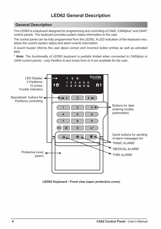
General DescriptionThe LED62 is a keyboard designed for programming and controlling of CA62, CA60plus* and СА40* control panels. The keyboard provides system status information to the user. The control panel can be fully programmed from the LED62. A LED indication of the keyboard visu-alizes the current system status and alarm events information. A sound buzzer informs the user about correct and incorrect button entries as well as activated alert. * Note: The functionality of LED62 keyboard is partially limited when connected to CA60plus or СА40 control panels - only Partition A and zones from to 6 are available for the user.
LED62 Keyboard - Front view (open protective cover)
LED Display: 2 Partitions,
12 zones,Trouble indication
Specialized buttons for Partitions controlling
Protective cover (open)
Buttons for data entering (codes, parameters)
Quick buttons for sending of alarm messages for:“PANIC ALARM”
“MEDICAL ALARM”
“FIRE ALARM”

CA62 Control Panel - User’s Manual 5
LED IndicationLED62 keyboard provides LED indications, which can be divided into three groups: For the Partitions status and the ARMING Mode; For the status of the control panel; For the status of the zones.
LED Indication for the Partitions status and the ARMING ModeDescribes the status of Partition А and В in the system, and also the type of ARMING Mode - “Full ARM” (see page 8), “Stay ARM” (see page 8) and “Instant ARM” (see page 9).
The two Partitions in the system are indicated with a “house” symbol with a capital letter (Partition А
with and Partition В with ). The type of the ARMING mode is indicated with a “man” symbol,
respectively for Partition А on the left side ( ) and for Partition В - on the right side ( ).
Symbol Indication Description
OFF
Partition А / Partition В is not ready for ARMING - there are activated detectors in the system, open zones; or the respec-tive group is not available in the system.
ON (green)
Partition А / Partition В is ready for ARMING - there are no activated detectors or open zones.Note: The “Partition A” symbol blinks in green during User or Manager programming operation.
ON (red) Partition А / Partition В is ARMED, regardless of the ARMING Mode.
Blinking (red) Exit time for leaving the premises in Partition А / Partition В is running.
OFF Partition А / Partition В is DISARMED, or is under “Full ARM” Mode.
ON (green) Partition А / Partition В is under “Stay ARM” Mode.
ON (red) Partition А / Partition В is under “Instant ARM” Mode.
Example:
“Partition А” symbol lights in green, symbol “man” lights off, means that the Partition А is DISARMED and is ready for ARMING. “Partition В” symbol lights in red, symbol “man” lights in green, means that Partition В is un-der “Stay ARM” Mode. The LEDs for zones 9 and 10 are blinking slowly, means that these zones are bypassed and there are still people staying in some premises of Partition B. ATTENTION: Only СА62 control panel can support working with both Partitions A and B at the same time!
6 CA62 Control Panel - User’s Manual
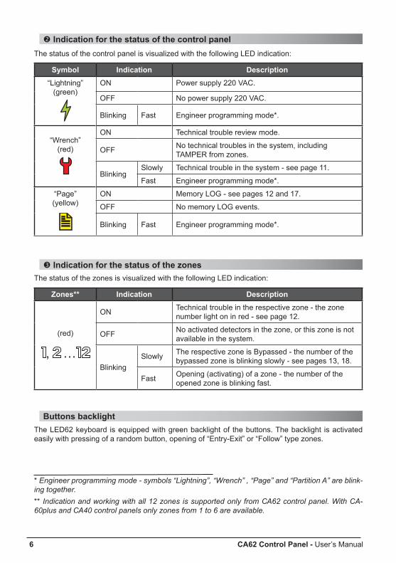
Indication for the status of the control panel The status of the control panel is visualized with the following LED indication:
Symbol Indication Description“Lightning”
(green)ON Power supply 220 VAC.
OFF No power supply 220 VAC.
Blinking Fast Engineer programming mode*.
“Wrench”(red)
ON Technical trouble review mode.
OFF No technical troubles in the system, including TAMPER from zones.
BlinkingSlowly Technical trouble in the system - see page 11.
Fast Engineer programming mode*.
“Page”(yellow)
ON Memory LOG - see pages 12 and 17.
OFF No memory LOG events.
Blinking Fast Engineer programming mode*.
Indication for the status of the zones The status of the zones is visualized with the following LED indication:
Zones** Indication Description
(red)
ON Technical trouble in the respective zone - the zone number light on in red - see page 12.
OFF No activated detectors in the zone, or this zone is not available in the system.
BlinkingSlowly The respective zone is Bypassed - the number of the
bypassed zone is blinking slowly - see pages 13, 18.
Fast Opening (activating) of a zone - the number of the opened zone is blinking fast.
Buttons backlightThe LED62 keyboard is equipped with green backlight of the buttons. The backlight is activated easily with pressing of a random button, opening of “Entry-Exit” or “Follow” type zones.
* Engineer programming mode - symbols “Lightning”, “Wrench” , “Page” and “Partition A” are blink-ing together.** Indication and working with all 12 zones is supported only from СА62 control panel. With CA-60plus and СА40 control panels only zones from 1 to 6 are available.
CA62 Control Panel - User’s Manual 7
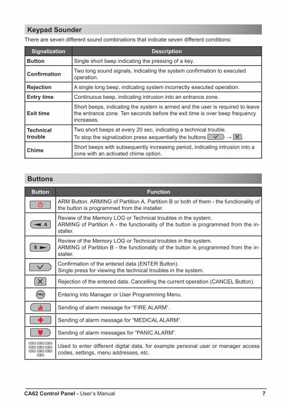
Keypad Sounder There are seven different sound combinations that indicate seven different conditions:
Signalization Description
Button Single short beep indicating the pressing of a key.
Confirmation Two long sound signals, indicating the system confirmation to executed operation.
Rejection A single long beep, indicating system incorrectly executed operation.
Entry time Continuous beep, indicating intrusion into an entrance zone.
Exit timeShort beeps, indicating the system is armed and the user is required to leave the entrance zone. Ten seconds before the exit time is over beep frequency increases.
Technical trouble
Two short beeps at every 20 sec, indicating a technical trouble. To stop the signalization press sequentially the buttons → .
Chime Short beeps with subsequently increasing period, indicating intrusion into a zone with an activated chime option.
Buttons
Button Function
ARM Button. ARMING of Partition А, Partition В or both of them - the functionality of the button is programmed from the installer.
Review of the Memory LOG or Technical troubles in the system. ARMING of Partition А - the functionality of the button is programmed from the in-staller.
Review of the Memory LOG or Technical troubles in the system. ARMING of Partition B - the functionality of the button is programmed from the in-staller.
Confirmation of the entered data (ENTER Button). Single press for viewing the technical troubles in the system.
Rejection of the entered data. Cancelling the current operation (CANCEL Button).
Entering into Manager or User Programming Menu.
Sending of alarm message for “FIRE ALARM”.
Sending of alarm message for “MEDICAL ALARM”.
Sending of alarm messages for “PANIC ALARM”.
Used to enter different digital data, for example personal user or manager access codes, settings, menu addresses, etc.

8 CA62 Control Panel - User’s Manual
LED62 Keypad Operation
Arming of Partition АThe system can be ARMED, when the symbols for “Partition А” and/ or “Partition В” light on in green.Note: The ARMING sequence depends on the model of the control panel and the programmed parameters in the Engineer Menu! Ask your installer which of the described below ARMING variants you have to use!ATTENTION: Only СА62 control panel can support working with both Partitions A and B at the same time!
“Full ARM” Mode of Partition A Full arming means all zones are secured. Anyone going into the entrance zone is required to enter a valid code*. Otherwise the alarm is started after the entry time is up.
ARMING vARIANT for “Full ARMING” of Partition A(with choosing the type of the ARMING Mode - default setting):
ARMING vARIANT for “Full ARMING” of Partition A (quick ARMING without user code with choosing the ARMING Mode type - default setting):
ARMING vARIANT for “Full ARMING” of Partition A (without choosing the type of the ARMING Mode - programmed from the installer):
ARMING vARIANT for “Full ARMING” of Partition A (quick ARMING without user code and ARMING Mode type - programmed from the installer):
At the end of the “Full ARM” procedure, regardless of the used arming variant, the symbol “Partition A” lights on in red, and the symbol “man” is off.
“Stay ARM” Mode of Partition A Stay arm means the user is allowed to remain in certain zones after the system is armed but the entrance zone is secured. Anyone going into the entrance zone is required to enter a valid code*. Otherwise the alarm is started after the entry time is up.Note: Certain users may not be permitted to ARM the system in “Stay ARM” Mode.
* To the user code are assigned rights to operate with Partition A, otherwise the system will reject the operation.
code* exit time
exittime
exit time
exit time
code*
CA62 Control Panel - User’s Manual 9
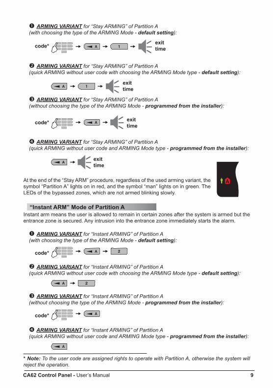
ARMING vARIANT for “Stay ARMING” of Partition A (with choosing the type of the ARMING Mode - default setting):
ARMING vARIANT for “Stay ARMING” of Partition A (quick ARMING without user code with choosing the ARMING Mode type - default setting):
ARMING vARIANT for “Stay ARMING” of Partition A (without choosing the type of the ARMING Mode - programmed from the installer):
ARMING vARIANT for “Stay ARMING” of Partition A (quick ARMING without user code and ARMING Mode type - programmed from the installer):
At the end of the “Stay ARM” procedure, regardless of the used arming variant, the symbol “Partition A” lights on in red, and the symbol “man” lights on in green. The LEDs of the bypassed zones, which are not armed blinking slowly.
“Instant ARM” Mode of Partition A Instant arm means the user is allowed to remain in certain zones after the system is armed but the entrance zone is secured. Any intrusion into the entrance zone immediately starts the alarm.
ARMING vARIANT for “Instant ARMING” of Partition A (with choosing the type of the ARMING Mode - default setting):
ARMING vARIANT for “Instant ARMING” of Partition A (quick ARMING without user code with choosing the ARMING Mode type - default setting):
ARMING vARIANT for “Instant ARMING” of Partition A (without choosing the type of the ARMING Mode - programmed from the installer):
ARMING vARIANT for “Instant ARMING” of Partition A (quick ARMING without user code and ARMING Mode type - programmed from the installer):
* Note: To the user code are assigned rights to operate with Partition A, otherwise the system will reject the operation.
code* exittime
exittime
exittime
exittime
code*
code*
code*
10 CA62 Control Panel - User’s Manual
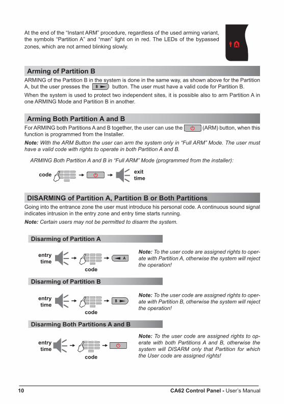
At the end of the “Instant ARM” procedure, regardless of the used arming variant, the symbols “Partition A” and “man” light on in red. The LEDs of the bypassed zones, which are not armed blinking slowly.
Arming of Partition ВARMING of the Partition В in the system is done in the same way, as shown above for the Partition A, but the user presses the button. The user must have a valid code for Partition B.When the system is used to protect two independent sites, it is possible also to arm Partition A in one ARMING Mode and Partition B in another.
Arming Both Partition А and ВFor ARMING both Partitions A and B together, the user can use the (ARM) button, when this function is programmed from the Installer. Note: With the ARM Button the user can arm the system only in “Full ARM” Mode. The user must have a valid code with rights to operate in both Partition A and B.
ARMING Both Partition A and B in “Full ARM” Mode (programmed from the installer):
DISARMING of Partition А, Partition В or Both Partitions Going into the entrance zone the user must introduce his personal code. A continuous sound signal indicates intrusion in the entry zone and entry time starts running. Note: Certain users may not be permitted to disarm the system.
Disarming of Partition А
Disarming of Partition В
Disarming Both Partitions A and B
code exittime
entrytime
entrytime
entrytime
code
code
code
Note: To the user code are assigned rights to oper-ate with Partition A, otherwise the system will reject the operation!
Note: To the user code are assigned rights to oper-ate with Partition B, otherwise the system will reject the operation!
Note: To the user code are assigned rights to op-erate with both Partitions A and B, otherwise the system will DISARM only that Partition for which the User code are assigned rights!
CA62 Control Panel - User’s Manual 11
Stopping the AlarmThe alarm is stopped by entering a valid personal code with assigned rights to operate with both Partitions in the system. ATTENTION: If you cannot stop the alarm using a valid user with assigned rights to operate with both Partitions, call the Engineer and your system technical support!
Panic ButtonsUsing the panic buttons the user can send alarm signals to the control panel without sounding the siren. To send an alarm signal:
• Press and hold for 2 seconds the button to send a FIRE alarm signal.• Press and hold for 2 seconds the button to send a MEDICAL alarm signal. • Press and hold for 2 seconds the button to send a PANIC alarm signal.
Ambush CodeThe ambush code is a personal code that disarms the system but still sends an alarm signal to the station to indicate that the user has been forcefully made to disarm the system.The ambush code is produced from a personal code by increasing the last digit by one. If the last digit is 9, it is replaced by 0.Example: Personal code: 4615 → Ambush code: 4616 Personal code: 4619 → Ambush code: 4610
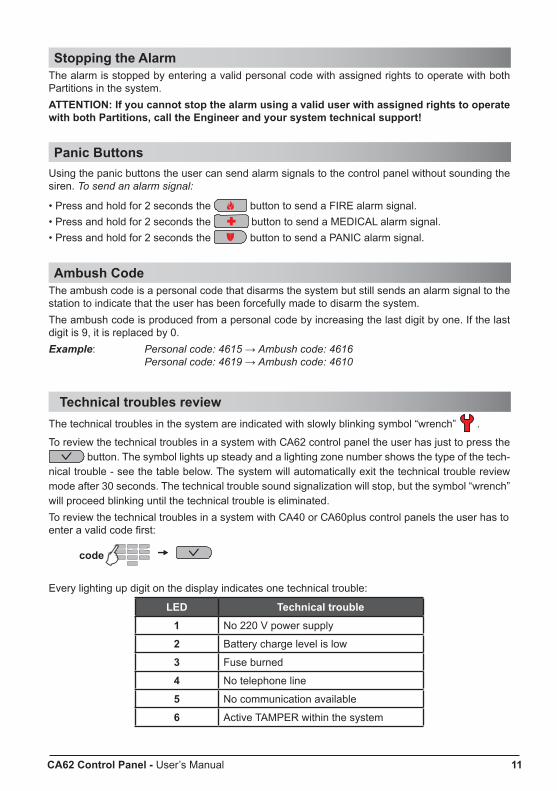
Technical troubles reviewThe technical troubles in the system are indicated with slowly blinking symbol “wrench” .
To review the technical troubles in a system with СА62 control panel the user has just to press the button. The symbol lights up steady and a lighting zone number shows the type of the tech-
nical trouble - see the table below. The system will automatically exit the technical trouble review mode after 30 seconds. The technical trouble sound signalization will stop, but the symbol “wrench” will proceed blinking until the technical trouble is eliminated. To review the technical troubles in a system with СА40 or СА60plus control panels the user has to enter a valid code first:
Every lighting up digit on the display indicates one technical trouble:
LED Technical trouble1 No 220 V power supply
2 Battery charge level is low
3 Fuse burned
4 No telephone line
5 No communication available
6 Active TAMPER within the system
code
12 CA62 Control Panel - User’s Manual
USER’S Programming Menu
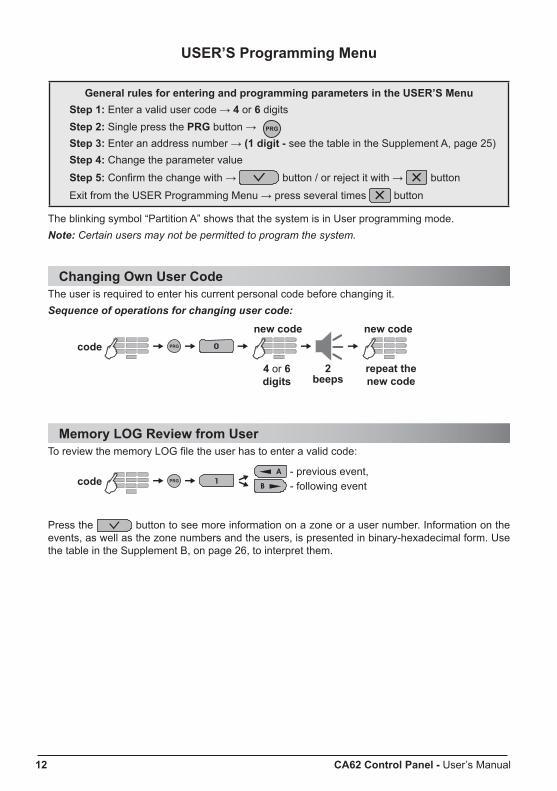
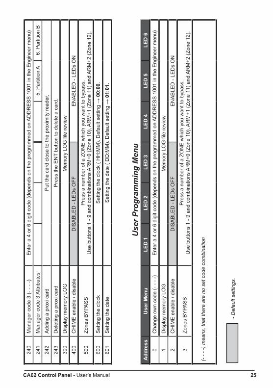
General rules for entering and programming parameters in the USER’S MenuStep 1: Enter a valid user code → 4 or 6 digitsStep 2: Single press the PRG button → Step 3: Enter an address number → (1 digit - see the table in the Supplement A, page 25)Step 4: Change the parameter value
Step 5: Confirm the change with → button / or reject it with → button
Exit from the USER Programming Menu → press several times button
The blinking symbol “Partition A” shows that the system is in User programming mode.Note: Certain users may not be permitted to program the system.
Changing Own User CodeThe user is required to enter his current personal code before changing it. Sequence of operations for changing user code:
Memory LOG Review from UserTo review the memory LOG file the user has to enter a valid code:
Press the button to see more information on a zone or a user number. Information on the events, as well as the zone numbers and the users, is presented in binary-hexadecimal form. Use the table in the Supplement B, on page 26, to interpret them.
4 or 6 digits
new code
repeat the new code
2 beeps
- previous event, - following event
code
code
new code
CA62 Control Panel - User’s Manual 13
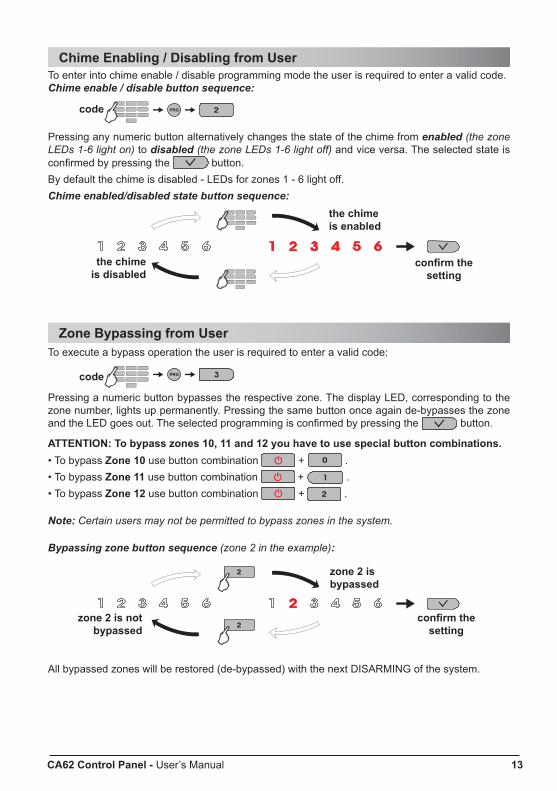
Chime Enabling / Disabling from UserTo enter into chime enable / disable programming mode the user is required to enter a valid code.Chime enable / disable button sequence:
Pressing any numeric button alternatively changes the state of the chime from enabled (the zone LEDs 1-6 light on) to disabled (the zone LEDs 1-6 light off) and vice versa. The selected state is confirmed by pressing the button. By default the chime is disabled - LEDs for zones 1 - 6 light off.Chime enabled/disabled state button sequence:
Zone Bypassing from UserTo execute a bypass operation the user is required to enter a valid code:
Pressing a numeric button bypasses the respective zone. The display LED, corresponding to the zone number, lights up permanently. Pressing the same button once again de-bypasses the zone and the LED goes out. The selected programming is confirmed by pressing the button.
ATTENTION: To bypass zones 10, 11 and 12 you have to use special button combinations.• To bypass Zone 10 use button combination + .• To bypass Zone 11 use button combination + .• To bypass Zone 12 use button combination + .
Note: Certain users may not be permitted to bypass zones in the system.
Bypassing zone button sequence (zone 2 in the example):
All bypassed zones will be restored (de-bypassed) with the next DISARMING of the system.
the chime is disabled
the chime is enabled
confirm the setting
zone 2 is not bypassed
zone 2 is bypassed
confirm the setting
code
code
14 CA62 Control Panel - User’s Manual
MANAGER’S Programming Menu
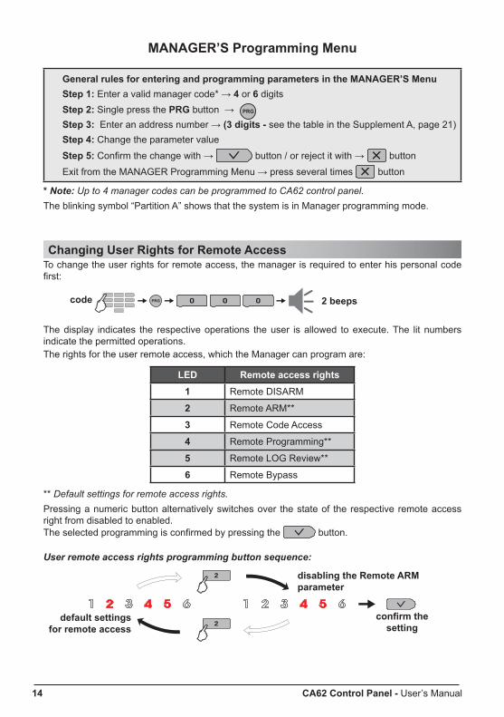
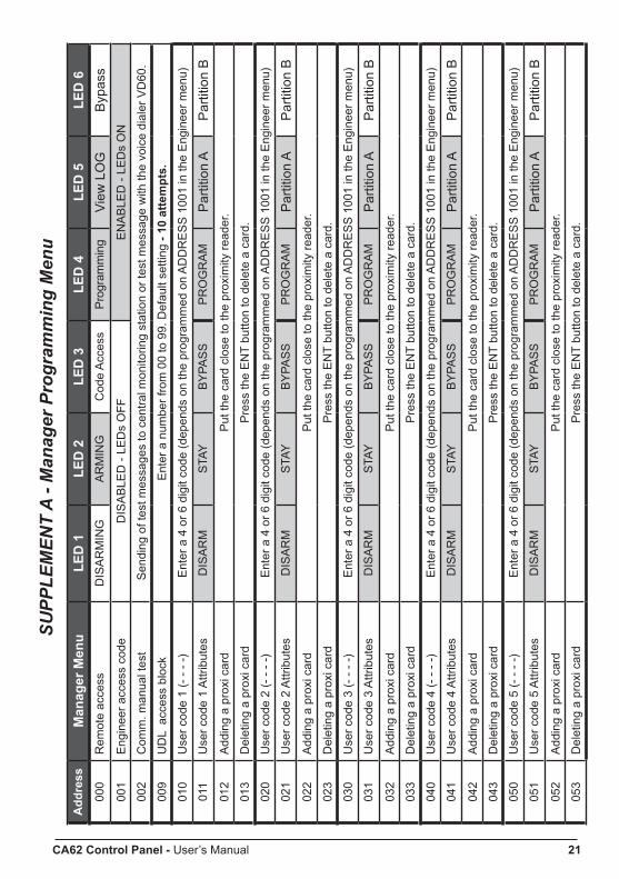
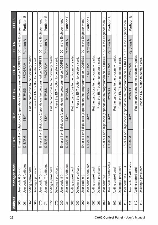
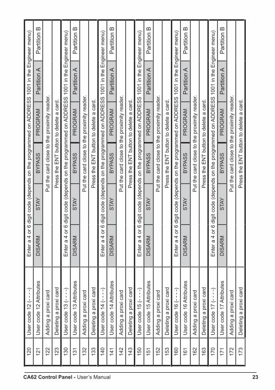
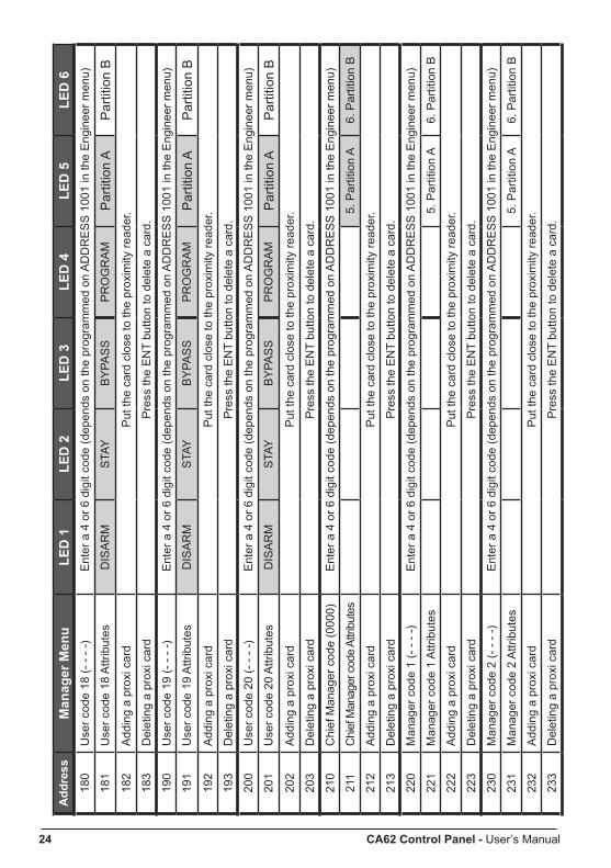
General rules for entering and programming parameters in the MANAGER’S MenuStep 1: Enter a valid manager code* → 4 or 6 digitsStep 2: Single press the PRG button → Step 3: Enter an address number → (3 digits - see the table in the Supplement A, page 21)Step 4: Change the parameter value
Step 5: Confirm the change with → button / or reject it with → button
Exit from the MANAGER Programming Menu → press several times button
* Note: Up to 4 manager codes can be programmed to CA62 control panel. The blinking symbol “Partition A” shows that the system is in Manager programming mode.
Changing User Rights for Remote Access To change the user rights for remote access, the manager is required to enter his personal code first:
The display indicates the respective operations the user is allowed to execute. The lit numbers indicate the permitted operations.The rights for the user remote access, which the Manager can program are:
LED Remote access rights1 Remote DISARM
2 Remote ARM**
3 Remote Code Access
4 Remote Programming**
5 Remote LOG Review**
6 Remote Bypass
** Default settings for remote access rights.Pressing a numeric button alternatively switches over the state of the respective remote access right from disabled to enabled.The selected programming is confirmed by pressing the button.
User remote access rights programming button sequence:
code 2 beeps
default settings for remote access
disabling the Remote ARM parameter
confirm the setting
CA62 Control Panel - User’s Manual 15
Enabling / Disabling the Engineer Code Access To enable / disable the Engineer code right to access the Engineer programming menu, the Man-ager is required to enter a valid code first:
Pressing any numeric button alternatively changes the state of the parameter from enabled (the zone LEDs 1-6 light on) to disabled (the zone LEDs 1-6 light off) and vice versa. The selected state is confirmed by pressing the button. By default the Engineer is allowed to enter the Engineer Menu - LEDs for zones 1 - 6 light on.Engineer access enabled/disabled state button sequence:
Sending of “Comm. Manual test” message At this address the Manager of the system can send a “Communication Manual Test” message to a central monitoring station or test message with the voice dialer VD60 (just in case there is integrated voice dialer VD60 to the CA62 control panel). The application of this function is to test the communi-cation part in the system from the manager, without need of sending the Engineer to the site.To send a “Comm. Manual Test” message, the manager is required to enter his personal code first:
The communicator will start transmitting test messages through the digital communicator to the central station first (if there are entered telephone numbers) and then through VD60 (if it is available in the system and there are entered telephone numbers).The Manager can exit the menu by pressing the button.
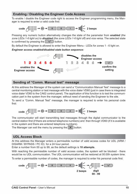
UDL Access BlockAt this address the Manager enters a permissible number of valid access codes for UDL (ARM / DISARM / BYPASS / PC ID) for a 24 hour period.Enter a number from 00 up to 99, as the default settings is 10 attempts.With reaching the permissible number of valid access codes, the system will be blocked - there would be no UDL communication. The UDL communication will be restored at 00:00h system time. To enter a permissible number of codes, the manager is required to enter his personal code first:
enables the Engineer access
disables the Engineer access
code 2 beeps
confirm the setting
code 2 beeps
2 beeps digit 00 - 99
code

16 CA62 Control Panel - User’s Manual
Changing of User Codes To change a user code the Manager is required to enter his personnel code first.User code change button sequence:
LEDs 3, 4, 5 and 6 light up to indicate the number of code digits left to be entered. Note: If 6-digit codes are used in the system, then LEDs 1, 2, 3, 4, 5 and 6 light up.The manager is expected to enter the new user code. Button sequence for entering new user code:
Changing of User Rights To change the User rights the Manager is required to enter his personnel code first.User rights change button sequence:
The display indicates the respective operations the user is allowed to execute. The lit numbers indicate the permitted operations:
LED User’s rights1 DISARM*
2 Stay ARM*
3 Bypass*
4 Programming*
5 Working with PARTITION A*
6 Working with PARTITION B
User rights programming button sequence:
Changing of Manager Codes Up to 4 different manager codes can be programmed in the СА62 control panel, i.e. there can be up to 4 Managers in the system - 1 Chief Manager and 3 sub-managers.
2 beepsUser No 01 - 20
4 or 6 digits
new code
repeat2 beeps
2 beepsUser No 01 - 20
code
code
new code
default settings
disabling the user programming in the system
confirm the setting
If the new code is repeated correctly the system will con-firm it with a sound signal.
Pressing a numeric button alternatively switches over the state of the respective user’s right from disabled to enabled. The selected programming is confirmed by pressing the button.
* Default settings for User’s rights. NOTE: Disabling all user rights will automatically erase the programmed code combination!

CA62 Control Panel - User’s Manual 17
The changing of the different Manager codes can be done at different addresses in the system: - Changing the Chief Manager code (see SUPPLEMENT А - ADDRESS 210) - Changing the Manager code No1 (see SUPPLEMENT А - ADDRESS 220) - Changing the Manager code No2 (see SUPPLEMENT А - ADDRESS 230) - Changing the Manager code No3 (see SUPPLEMENT А - ADDRESS 240)
To change his code the manager is required to enter his current manager code before changing it.Manager code change button sequence:
LEDs 3, 4, 5 and 6 light up to indicate the number of code digits left to be entered. Note: If 6-digit codes are used in the system, then LEDs 1, 2, 3, 4, 5 and 6 light up.The manager is expected to enter his new code. Button sequence for entering new manager code:
Changing of Manager Rights To change his rights the manager is required to enter his current manager code.Manager rights change button sequence:
Pressing a numeric button alternatively switches over the state of the respective manager’s right from disabled to enabled. The display indicates the respective operations the manager is allowed to execute. The lit numbers indicate the permitted operations:
LED Manager rights5 Working with PARTITION A*
6 Working with PARTITION B*
The selected programming is confirmed by pressing the button.
Memory LOG review from Manager To review the memory LOG of events the manager is required to enter his code:
Press the button to see more information on a zone number or a user code. To go back to the memory LOG list press the button again. Use the table in the Supplement B, on page 26, to interpret them.
2 beepsManagerADDRESS 2х
code
4 or 6 digits
new code
repeatnew code
2 beeps
code
2 beepsManagerADDRESS 2х
If the new code is repeated correctly the sys-tem will confirm it with a sound signal and the system will exit automatically from the Manager programming menu.
- previous event, - following event
code
* Default settings for Chief Manager in the system. For sub-managers No 1, 2 and 3 there are no pro-grammed rights by default.NOTE: Disabling all manager rights will automati-cally erase the programmed code combination!

18 CA62 Control Panel - User’s Manual
Chime Enabling / Disabling from ManagerTo enter in the enable / disable chime mode, the manager is required to enter his code.Chime enable/disable button sequence:
Pressing a numeric button alternatively switches over the state of the chime from disabled to ena-bled. The selected programming is confirmed by pressing the button.
By default the chime is disabled - LEDs for zones 1 - 6 light off. See also the example for chime enable / disable from User - page 12.
Zone Bypassing from ManagerTo execute a bypass operation the manager is required to enter a valid code:
Pressing a numeric button bypasses the respective zone. The display LED, corresponding to the zone number, lights up permanently. Pressing the same button once again de-bypasses the zone and the LED goes out. The selected programming is confirmed by pressing the button.See also the example for zone bypassing from User - page 13.
Setting the Clock To set the clock the manager is required to enter his personal code. The set entries are visualized in binary-hexadecimal form.Button sequence for setting the clock:
Setting the DateTo set the date the manager is required to enter his personal code. The set entries are visualized in binary-hexadecimal form.Button sequence for setting the date:
Adding a Proximity CardTo use proximity cards the system has to be equipped with a proximity card reader. Button sequence for adding a proximity card:
Deleting a Proximity CardButton sequence for deleting a proximity card:
2 beepscode
2 beepscode
New time
New date
User No 01-20 orManager ADDRESS 2х
2 beeps
User / Manager No 2 beeps
code
2 beeps
code
2 beeps
code
code
(HH:MM)
(DD:MM)
CA62 Control Panel - User’s Manual 19
PR62 Proximity Card Reader Description
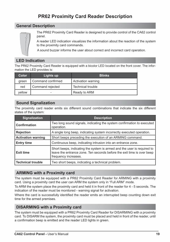
General DescriptionThe PR62 Proximity Card Reader is designed to provide control of the CA62 control panel.A reader LED indication visualizes the information about the reaction of the system to the proximity card commands.A sound buzzer informs the user about correct and incorrect card operation.
LED IndicationThe PR62 Proximity Card Reader is equipped with a bicolor LED located on the front cover. The infor-mation the LED provides is:
Color Lights up Blinksgreen Command confirmed Activation warning
red Command rejected Technical trouble
yellow - Ready to ARM
Sound SignalizationThe proximity card reader emits six different sound combinations that indicate the six different states of the system:
Signalization Description
Confirmation Two long sound signals, indicating the system confirmation to executed operation.
Rejection A single long beep, indicating system incorrectly executed operation.Activation warning Short beeps preceding the execution of an ARMING command.Entry time Continuous beep, indicating intrusion into an entrance zone.
Exit timeShort beeps, indicating the system is armed and the user is required to leave the entrance zone. Ten seconds before the exit time is over beep frequency increases.
Technical trouble Two short beeps, indicating a technical problem.
ARMING with a Proximity cardThe system must be equipped with a PR62 Proximity Card Reader for ARMING with a proximity card. Using a proximity card the user can ARM the system only in “Full ARM” mode.To ARM the system place the proximity card and held it in front of the reader for 4 - 5 seconds. The indication of the reader must be monitored - warning signal for activation.Where the card is successfully identified the reader emits an interrupted beep counting down exit time for the armed premises.
DISARMING with a Proximity cardThe system must be equipped with a PR62 Proximity Card Reader for DISARMING with a proximity card. To DISARM the system, the proximity card must be placed and held in front of the reader, until a confirmation beep is emitted and the reader LED lights in green.
20 CA62 Control Panel - User’s Manual
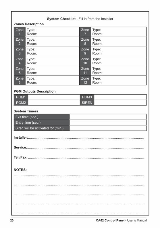
System Checklist - Fill in from the InstallerZones Description
Zone 1
Type:Room:
Zone 7
Type:Room:
Zone 2
Type:Room:
Zone 8
Type:Room:
Zone3
Type:Room:
Zone 9
Type:Room:
Zone 4
Type:Room:
Zone 10
Type:Room:
Zone 5
Type:Room:
Zone 11
Type:Room:
Zone 6
Type:Room:
Zone 12
Type:Room:
PGM Outputs DescriptionPGM1 PGM3PGM2 SIREN
System TimersExit time (sec.)Entry time (sec.)Siren will be activated for (min.)
Installer:.........................................................................................................................
Service:..........................................................................................................................
Tel./Fax: .........................................................................................................................
NOTES:........................................................................................................................................
........................................................................................................................................
........................................................................................................................................
........................................................................................................................................
........................................................................................................................................
CA62 Control Panel - User’s Manual 21
SUPP
LEM
ENT
A - M
anag
er P
rogr
amm
ing
Men
uA
ddre
ssM
anag
er M
enu
LED
1
LED
2
LED
3
LED
4
LED
5
LED
6
000
Rem
ote
acce
ssD
ISA
RM
ING
AR
MIN
GC
ode
Acc
ess
Prog
ram
min
gVi
ew L
OG
Byp
ass
001
Eng
inee
r acc
ess
code
DIS
AB
LED
- LE
Ds
OFF
EN
AB
LED
- LE
Ds
ON
002
Com
m. m
anua
l tes
t S
endi
ng o
f tes
t mes
sage
s to
cen
tral m
onito
ring
stat
ion
or te
st m
essa
ge w
ith th
e vo
ice
dial
er V
D60
.
009
UD
L a
cces
s bl
ock
Ent
er a
num
ber f
rom
00
to 9
9. D
efau
lt se
tting
- 10
atte
mpt
s.
010
Use
r cod
e 1
(- -
- -)
Ent
er a
4 o
r 6 d
igit
code
(dep
ends
on
the
prog
ram
med
on
AD
DR
ES
S 1
001
in th
e E
ngin
eer m
enu)
011
Use
r cod
e 1
Attr
ibut
esD
ISA
RM
STA
Y B
YPA
SS
PR
OG
RA
MP
artit
ion
AP
artit
ion
B01
2A
ddin
g a
prox
i car
dP
ut th
e ca
rd c
lose
to th
e pr
oxim
ity re
ader
.
013
Del
etin
g a
prox
i car
dP
ress
the
EN
T bu
tton
to d
elet
e a
card
.
020
Use
r cod
e 2
(- -
- -)
Ent
er a
4 o
r 6 d
igit
code
(dep
ends
on
the
prog
ram
med
on
AD
DR
ES
S 1
001
in th
e E
ngin
eer m
enu)
021
Use
r cod
e 2
Attr
ibut
esD
ISA
RM
STA
Y B
YPA
SS
PR
OG
RA
MP
artit
ion
AP
artit
ion
B02
2A
ddin
g a
prox
i car
dP
ut th
e ca
rd c
lose
to th
e pr
oxim
ity re
ader
.
023
Del
etin
g a
prox
i car
dP
ress
the
EN
T bu
tton
to d
elet
e a
card
.
030
Use
r cod
e 3
(- -
- -)
Ent
er a
4 o
r 6 d
igit
code
(dep
ends
on
the
prog
ram
med
on
AD
DR
ES
S 1
001
in th
e E
ngin
eer m
enu)
031
Use
r cod
e 3
Attr
ibut
esD
ISA
RM
STA
Y B
YPA
SS
PR
OG
RA
MP
artit
ion
AP
artit
ion
B03
2A
ddin
g a
prox
i car
dP
ut th
e ca
rd c
lose
to th
e pr
oxim
ity re
ader
.
033
Del
etin
g a
prox
i car
dP
ress
the
EN
T bu
tton
to d
elet
e a
card
.
040
Use
r cod
e 4
(- -
- -)
Ent
er a
4 o
r 6 d
igit
code
(dep
ends
on
the
prog
ram
med
on
AD
DR
ES
S 1
001
in th
e E
ngin
eer m
enu)
041
Use
r cod
e 4
Attr
ibut
esD
ISA
RM
STA
Y B
YPA
SS
PR
OG
RA
MP
artit
ion
AP
artit
ion
B04
2A
ddin
g a
prox
i car
dP
ut th
e ca
rd c
lose
to th
e pr
oxim
ity re
ader
.
043
Del
etin
g a
prox
i car
dP
ress
the
EN
T bu
tton
to d
elet
e a
card
.
050
Use
r cod
e 5
(- -
- -)
Ent
er a
4 o
r 6 d
igit
code
(dep
ends
on
the
prog
ram
med
on
AD
DR
ES
S 1
001
in th
e E
ngin
eer m
enu)
051
Use
r cod
e 5
Attr
ibut
esD
ISA
RM
STA
Y B
YPA
SS
PR
OG
RA
MP
artit
ion
AP
artit
ion
B05
2A
ddin
g a
prox
i car
dP
ut th
e ca
rd c
lose
to th
e pr
oxim
ity re
ader
.
053
Del
etin
g a
prox
i car
dP
ress
the
EN
T bu
tton
to d
elet
e a
card
.
22 CA62 Control Panel - User’s Manual
Add
ress
Man
ager
Men
uLE
D 1
LE
D 2
LE
D 3
LE
D 4
LE
D 5
LE
D 6
06
0U
ser c
ode
6 (-
- - -
)E
nter
a 4
or 6
dig
it co
de (d
epen
ds o
n th
e pr
ogra
mm
ed o
n A
DD
RE
SS
100
1 in
the
Eng
inee
r men
u)
061
Use
r cod
e 6
Attr
ibut
esD
ISA
RM
STA
Y B
YPA
SS
PR
OG
RA
MP
artit
ion
AP
artit
ion
B06
2A
ddin
g a
prox
i car
dP
ut th
e ca
rd c
lose
to th
e pr
oxim
ity re
ader
.
063
Del
etin
g a
prox
i car
dP
ress
the
EN
T bu
tton
to d
elet
e a
card
.
070
Use
r cod
e 7
(- -
- -)
Ent
er a
4 o
r 6 d
igit
code
(dep
ends
on
the
prog
ram
med
on
AD
DR
ES
S 1
001
in th
e E
ngin
eer m
enu)
071
Use
r cod
e 7
Attr
ibut
esD
ISA
RM
STA
Y B
YPA
SS
PR
OG
RA
MP
artit
ion
AP
artit
ion
B07
2A
ddin
g a
prox
i car
dP
ut th
e ca
rd c
lose
to th
e pr
oxim
ity re
ader
.
073
Del
etin
g a
prox
i car
dP
ress
the
EN
T bu
tton
to d
elet
e a
card
.
080
Use
r cod
e 8
(- -
- -)
Ent
er a
4 o
r 6 d
igit
code
(dep
ends
on
the
prog
ram
med
on
AD
DR
ES
S 1
001
in th
e E
ngin
eer m
enu)
081
Use
r cod
e 8
Attr
ibut
esD
ISA
RM
STA
Y B
YPA
SS
PR
OG
RA
MP
artit
ion
AP
artit
ion
B08
2A
ddin
g a
prox
i car
dP
ut th
e ca
rd c
lose
to th
e pr
oxim
ity re
ader
.
083
Del
etin
g a
prox
i car
dP
ress
the
EN
T bu
tton
to d
elet
e a
card
.
090
Use
r cod
e 9
(- -
- -)
Ent
er a
4 o
r 6 d
igit
code
(dep
ends
on
the
prog
ram
med
on
AD
DR
ES
S 1
001
in th
e E
ngin
eer m
enu)
091
Use
r cod
e 9
Attr
ibut
esD
ISA
RM
STA
Y B
YPA
SS
PR
OG
RA
MP
artit
ion
AP
artit
ion
B09
2A
ddin
g a
prox
i car
dP
ut th
e ca
rd c
lose
to th
e pr
oxim
ity re
ader
.
093
Del
etin
g a
prox
i car
dP
ress
the
EN
T bu
tton
to d
elet
e a
card
.
100
Use
r cod
e 10
(- -
- -)
Ent
er a
4 o
r 6 d
igit
code
(dep
ends
on
the
prog
ram
med
on
AD
DR
ES
S 1
001
in th
e E
ngin
eer m
enu)
101
Use
r cod
e 10
Attr
ibut
esD
ISA
RM
STA
Y B
YPA
SS
PR
OG
RA
MP
artit
ion
AP
artit
ion
B10
2A
ddin
g a
prox
i car
dP
ut th
e ca
rd c
lose
to th
e pr
oxim
ity re
ader
.
103
Del
etin
g a
prox
i car
dP
ress
the
EN
T bu
tton
to d
elet
e a
card
.
110
Use
r cod
e 11
(- -
- -)
Ent
er a
4 o
r 6 d
igit
code
(dep
ends
on
the
prog
ram
med
on
AD
DR
ES
S 1
001
in th
e E
ngin
eer m
enu)
111
Use
r cod
e 11
Attr
ibut
esD
ISA
RM
STA
Y B
YPA
SS
PR
OG
RA
MP
artit
ion
AP
artit
ion
B11
2A
ddin
g a
prox
i car
dP
ut th
e ca
rd c
lose
to th
e pr
oxim
ity re
ader
.
113
Del
etin
g a
prox
i car
dP
ress
the
EN
T bu
tton
to d
elet
e a
card
.
CA62 Control Panel - User’s Manual 23
120
Use
r cod
e 12
(- -
- -)
Ent
er a
4 o
r 6 d
igit
code
(dep
ends
on
the
prog
ram
med
on
AD
DR
ES
S 1
001
in th
e E
ngin
eer m
enu)
121
Use
r cod
e 12
Attr
ibut
esD
ISA
RM
STA
Y B
YPA
SS
PR
OG
RA
MP
artit
ion
AP
artit
ion
B12
2A
ddin
g a
prox
i car
dP
ut th
e ca
rd c
lose
to th
e pr
oxim
ity re
ader
.
123
Del
etin
g a
prox
i car
dP
ress
the
EN
T bu
tton
to d
elet
e a
card
.
130
Use
r cod
e 13
(- -
- -)
Ent
er a
4 o
r 6 d
igit
code
(dep
ends
on
the
prog
ram
med
on
AD
DR
ES
S 1
001
in th
e E
ngin
eer m
enu)
131
Use
r cod
e 13
Attr
ibut
esD
ISA
RM
STA
Y B
YPA
SS
PR
OG
RA
MP
artit
ion
AP
artit
ion
B13
2A
ddin
g a
prox
i car
dP
ut th
e ca
rd c
lose
to th
e pr
oxim
ity re
ader
.
133
Del
etin
g a
prox
i car
dP
ress
the
EN
T bu
tton
to d
elet
e a
card
.
140
Use
r cod
e 14
(- -
- -)
Ent
er a
4 o
r 6 d
igit
code
(dep
ends
on
the
prog
ram
med
on
AD
DR
ES
S 1
001
in th
e E
ngin
eer m
enu)
141
Use
r cod
e 14
Attr
ibut
esD
ISA
RM
STA
Y B
YPA
SS
PR
OG
RA
MP
artit
ion
AP
artit
ion
B14
2A
ddin
g a
prox
i car
dP
ut th
e ca
rd c
lose
to th
e pr
oxim
ity re
ader
.
143
Del
etin
g a
prox
i car
dP
ress
the
EN
T bu
tton
to d
elet
e a
card
.
150
Use
r cod
e 15
(- -
- -)
Ent
er a
4 o
r 6 d
igit
code
(dep
ends
on
the
prog
ram
med
on
AD
DR
ES
S 1
001
in th
e E
ngin
eer m
enu)
151
Use
r cod
e 15
Attr
ibut
esD
ISA
RM
STA
Y B
YPA
SS
PR
OG
RA
MP
artit
ion
AP
artit
ion
B15
2A
ddin
g a
prox
i car
dP
ut th
e ca
rd c
lose
to th
e pr
oxim
ity re
ader
.
153
Del
etin
g a
prox
i car
dP
ress
the
EN
T bu
tton
to d
elet
e a
card
.
160
Use
r cod
e 16
(- -
- -)
Ent
er a
4 o
r 6 d
igit
code
(dep
ends
on
the
prog
ram
med
on
AD
DR
ES
S 1
001
in th
e E
ngin
eer m
enu)
161
Use
r cod
e 16
Attr
ibut
esD
ISA
RM
STA
Y B
YPA
SS
PR
OG
RA
MP
artit
ion
AP
artit
ion
B16
2A
ddin
g a
prox
i car
dP
ut th
e ca
rd c
lose
to th
e pr
oxim
ity re
ader
.
163
Del
etin
g a
prox
i car
dP
ress
the
EN
T bu
tton
to d
elet
e a
card
.
170
Use
r cod
e 17
(- -
- -)
Ent
er a
4 o
r 6 d
igit
code
(dep
ends
on
the
prog
ram
med
on
AD
DR
ES
S 1
001
in th
e E
ngin
eer m
enu)
171
Use
r cod
e 17
Attr
ibut
esD
ISA
RM
STA
Y B
YPA
SS
PR
OG
RA
MP
artit
ion
AP
artit
ion
B17
2A
ddin
g a
prox
i car
dP
ut th
e ca
rd c
lose
to th
e pr
oxim
ity re
ader
.
173
Del
etin
g a
prox
i car
dP
ress
the
EN
T bu
tton
to d
elet
e a
card
.
24 CA62 Control Panel - User’s Manual
Add
ress
Man
ager
Men
uLE
D 1
LE
D 2
LE
D 3
LE
D 4
LE
D 5
LE
D 6
18
0U
ser c
ode
18 (-
- - -
)E
nter
a 4
or 6
dig
it co
de (d
epen
ds o
n th
e pr
ogra
mm
ed o
n A
DD
RE
SS
100
1 in
the
Eng
inee
r men
u)
181
Use
r cod
e 18
Attr
ibut
esD
ISA
RM
STA
Y B
YPA
SS
PR
OG
RA
MP
artit
ion
AP
artit
ion
B18
2A
ddin
g a
prox
i car
dP
ut th
e ca
rd c
lose
to th
e pr
oxim
ity re
ader
.
183
Del
etin
g a
prox
i car
dP
ress
the
EN
T bu
tton
to d
elet
e a
card
.
190
Use
r cod
e 19
(- -
- -)
Ent
er a
4 o
r 6 d
igit
code
(dep
ends
on
the
prog
ram
med
on
AD
DR
ES
S 1
001
in th
e E
ngin
eer m
enu)
191
Use
r cod
e 19
Attr
ibut
esD
ISA
RM
STA
Y B
YPA
SS
PR
OG
RA
MP
artit
ion
AP
artit
ion
B19
2A
ddin
g a
prox
i car
dP
ut th
e ca
rd c
lose
to th
e pr
oxim
ity re
ader
.
193
Del
etin
g a
prox
i car
dP
ress
the
EN
T bu
tton
to d
elet
e a
card
.
200
Use
r cod
e 20
(- -
- -)
Ent
er a
4 o
r 6 d
igit
code
(dep
ends
on
the
prog
ram
med
on
AD
DR
ES
S 1
001
in th
e E
ngin
eer m
enu)
201
Use
r cod
e 20
Attr
ibut
esD
ISA
RM
STA
Y B
YPA
SS
PR
OG
RA
MP
artit
ion
AP
artit
ion
B20
2A
ddin
g a
prox
i car
dP
ut th
e ca
rd c
lose
to th
e pr
oxim
ity re
ader
.
203
Del
etin
g a
prox
i car
dP
ress
the
EN
T bu
tton
to d
elet
e a
card
.
210
Chi
ef M
anag
er c
ode
(000
0)E
nter
a 4
or 6
dig
it co
de (d
epen
ds o
n th
e pr
ogra
mm
ed o
n A
DD
RE
SS
100
1 in
the
Eng
inee
r men
u)
211
Chi
ef M
anag
er c
ode
Attri
bute
s5.
Par
titio
n A
6. P
artit
ion
B
212
Add
ing
a pr
oxi c
ard
Put
the
card
clo
se to
the
prox
imity
read
er.
213
Del
etin
g a
prox
i car
dP
ress
the
EN
T bu
tton
to d
elet
e a
card
.
220
Man
ager
cod
e 1
(- -
- -)
Ent
er a
4 o
r 6 d
igit
code
(dep
ends
on
the
prog
ram
med
on
AD
DR
ES
S 1
001
in th
e E
ngin
eer m
enu)
221
Man
ager
cod
e 1
Attr
ibut
es
5. P
artit
ion
A6.
Par
titio
n B
222
Add
ing
a pr
oxi c
ard
Put
the
card
clo
se to
the
prox
imity
read
er.
223
Del
etin
g a
prox
i car
dP
ress
the
EN
T bu
tton
to d
elet
e a
card
.
230
Man
ager
cod
e 2
(- -
- -)
Ent
er a
4 o
r 6 d
igit
code
(dep
ends
on
the
prog
ram
med
on
AD
DR
ES
S 1
001
in th
e E
ngin
eer m
enu)
231
Man
ager
cod
e 2
Attr
ibut
es5.
Par
titio
n A
6. P
artit
ion
B
232
Add
ing
a pr
oxi c
ard
Put
the
card
clo
se to
the
prox
imity
read
er.
233
Del
etin
g a
prox
i car
dP
ress
the
EN
T bu
tton
to d
elet
e a
card
.
CA62 Control Panel - User’s Manual 25
240
Man
ager
cod
e 3
(- -
- -)
Ent
er a
4 o
r 6 d
igit
code
(dep
ends
on
the
prog
ram
med
on
AD
DR
ES
S 1
001
in th
e E
ngin
eer m
enu)
241
Man
ager
cod
e 3
Attr
ibut
es
5. P
artit
ion
A6.
Par
titio
n B
242
Add
ing
a pr
oxi c
ard
Put
the
card
clo
se to
the
prox
imity
read
er.
243
Del
etin
g a
prox
i car
dP
ress
the
EN
T bu
tton
to d
elet
e a
card
.
300
Dis
play
mem
ory
LOG
Mem
ory
LOG
file
revi
ew.
400
Ch
IME
ena
ble
/ dis
able
DIS
AB
LED
- LE
Ds
OFF
EN
AB
LED
- LE
Ds
ON
500
Zone
s B
YPA
SS
Pre
ss a
num
ber o
f a Z
ON
E w
hich
you
wan
t to
bypa
ss.
Use
but
tons
1 -
9 an
d co
mbi
natio
ns A
RM
+0 (Z
one
10),
AR
M+1
(Zon
e 11
) and
AR
M+2
(Zon
e 12
),
600
Set
ting
the
cloc
kS
ettin
g th
e cl
ock
( HH
:MM
). D
efau
lt se
tting
→ 0
0:00
.
601
Set
ting
the
date
Set
ting
the
date
( D
D:M
M).
Def
ault
setti
ng →
01:
01.
Use
r Pro
gram
min
g M
enu
Add
ress
Use
r Men
uLE
D 1
LE
D 2
LE
D 3
LE
D 4
LE
D 5
LE
D 6
0
Cha
nge
own
code
(- -
- -)
Ent
er a
4 o
r 6 d
igit
code
(dep
ends
on
the
prog
ram
med
on
AD
DR
ES
S 1
001
in th
e E
ngin
eer m
enu)
1D
ispl
ay m
emor
y LO
GM
emor
y LO
G fi
le re
view
.
2C
hIM
E e
nabl
e / d
isab
leD
ISA
BLE
D -
LED
s O
FFE
NA
BLE
D -
LED
s O
N
3Zo
nes
BY
PAS
SP
ress
a n
umbe
r of a
ZO
NE
whi
ch y
ou w
ant t
o by
pass
. U
se b
utto
ns 1
- 9
and
com
bina
tions
AR
M+0
(Zon
e 10
), A
RM
+1 (Z
one
11) a
nd A
RM
+2 (Z
one
12),
(- -
- -) m
eans
, tha
t the
re a
re n
o se
t cod
e co
mbi
natio
n
- D
efau
lt se
tting
s.
26 CA62 Control Panel - User’s Manual
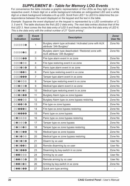
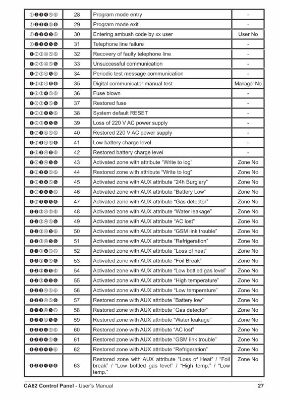
SUPPLEMENT B - Table for Memory LOG EventsFor convenience the table includes a graphic representation of the LEDs as they light up for the respective event. A black digit on a white background indicates an extinguished LED and a white digit on a black background indicates a lit up LED. Scroll from LED 1 to LED 6 to determine the cor-respondence between the event displayed on the keypad and the text in the table. Example: Suppose the event displayed on the keypad is represented by a LED combination of 2, 3, 5 and 6. The table discloses the first LED 2 data entry. The next data entries disclose that of the first LED 3. Next comes the first data entry of LED 5 and finally comes the first data entry of LED 6. This is the data entry with the ordinal number of 27 “Quick arming”.
LED Indication
Event number Description Zone/
User No
1 Burglary alarm type activated / Activated zone with AUX attribute “24h Burglary”
Zone No
2 Burglary alarm type deactivated / Restored zone with AUX attribute “24h Burglary”
Zone No
3 Fire type alarm event in xx zone Zone No
4 Fire type restoring event in xx zone Zone No
5 Panic type alarm event in xx zone Zone No
6 Panic type restoring event in xx zone Zone No
7 Tamper type alarm event in xx zone Zone No
8 Tamper type restoring event in xx zone Zone No
9 Medical type alarm event in xx zone Zone No
10 Medical type restoring event in xx zone Zone No
11 Burglary Alarm type xx zone bypass Zone No
12 Burglary Alarm type xx zone bypass restoring Zone No
13 Fire type xx zone bypass Zone No
14 Fire type xx zone bypass restoring Zone No
15 Panic type xx zone bypass Zone No
16 Panic type xx zone bypass restoring Zone No
17 Tamper type xx zone bypass Zone No
18 Tamper type xx zone bypass restoring Zone No
19 Medical type xx zone bypass Zone No
20 Medical type xx zone bypass restoring Zone No
21 Disarm by xx user User No
22 Remote disarming by xx user User No
23 Disarming by key-switch in xx zone Zone No
24 Arming by xx user User No
25 Remote arming by xx user User No
26 Arming by key-switch in xx zone Zone No
27 Quick arm type arming -
CA62 Control Panel - User’s Manual 27
28 Program mode entry -
29 Program mode exit -
30 Entering ambush code by xx user User No
31 Telephone line failure -
32 Recovery of faulty telephone line -
33 Unsuccessful communication -
34 Periodic test message communication -
35 Digital communicator manual test Manager No
36 Fuse blown -
37 Restored fuse -
38 System default RESET -
39 Loss of 220 V AC power supply -
40 Restored 220 V AC power supply -
41 Low battery charge level -
42 Restored battery charge level -
43 Activated zone with attribute “Write to log” Zone No
44 Restored zone with attribute “Write to log” Zone No
45 Activated zone with AUX attribute “24h Burglary” Zone No
46 Activated zone with AUX attribute “Battery Low” Zone No
47 Activated zone with AUX attribute “Gas detector” Zone No
48 Activated zone with AUX attribute “Water leakage” Zone No
49 Activated zone with AUX attribute “AC lost” Zone No
50 Activated zone with AUX attribute “GSM link trouble” Zone No
51 Activated zone with AUX attribute “Refrigeration” Zone No
52 Activated zone with AUX attribute “Loss of heat” Zone No
53 Activated zone with AUX attribute “Foil Break” Zone No
54 Activated zone with AUX attribute “Low bottled gas level” Zone No
55 Activated zone with AUX attribute “high temperature” Zone No
56 Activated zone with AUX attribute “Low temperature” Zone No
57 Restored zone with AUX attribute “Battery low” Zone No
58 Restored zone with AUX attribute “Gas detector” Zone No
59 Restored zone with AUX attribute “Water leakage” Zone No
60 Restored zone with AUX attribute “AC lost” Zone No
61 Restored zone with AUX attribute “GSM link trouble” Zone No
62 Restored zone with AUX attribute “Refrigeration” Zone No
63Restored zone with AUX attribute “Loss of heat” / “Foil break” / “Low bottled gas level” / “high temp.” / “Low temp.”
Zone No

www.teletek-electronics.comAddress: Bulgaria, 1407 Sofia, 14A Srebarna Str.Tel.: (+359 2) 9694 800, Fax: (+359 2) 962 52 13e-mail: [email protected] 18
0205
99_E
nglis
h, R
evC
, 01/
2010