ca2t: cooperative antenna arrays technique for pinpoint indoor localization
TRANSCRIPT

Procedia Computer Science 34 ( 2014 ) 392 – 399
1877-0509 © 2014 Elsevier B.V. This is an open access article under the CC BY-NC-ND license (http://creativecommons.org/licenses/by-nc-nd/3.0/).Selection and peer-review under responsibility of Conference Program Chairsdoi: 10.1016/j.procs.2014.07.044
ScienceDirectAvailable online at www.sciencedirect.com
The 11th International Conference on Mobile Systems and Pervasive Computing(MobiSPC-2014)
CA2T: Cooperative Antenna Arrays Technique for Pinpoint IndoorLocalization
Xuyu Wanga, Shiwen Maoa,∗, Santosh Pandeyb, Prathima AgrawalaaDepartment of Electrical and Computer Engineering, 200 Broun Hall, Auburn University, Auburn, AL 36849-5201 USA
bCisco Systems, Inc., 170 West Tasman Dr., San Jose, CA 95134 USA
Abstract
Location-based service has a great potential in the indoor environment, making it important to develop accurate indoor localizationtechniques. In this paper, we consider AOA based indoor localization, which can generally achieve higher accuracy of localizationthan other approaches. We propose to use cooperative APs with antenna arrays for accurate indoor localization. With the proposedCooperative Antenna Arrays Technique (CA2T), we first estimate the arriving angles for all the multipath components using theMUSIC algorithm, and then exploit the geometric relationship among the angles to identify the LOS angles. The user location canbe computed with the LOS angles and the accurate, known distance between the two APs. The proposed scheme is validated withsimulations and is shown to outperform an existing scheme with considerable gains.c© 2014 The Authors. Published by Elsevier B.V.Selection and peer-review under responsibility of Elhadi M. Shakshuki.
Keywords: Indoor localization, antenna array, cooperation, MUSIC, LOS identification, Optimization.
1. Introduction
With the proliferation of mobile computing devices, location-based services have attracted considerable interest,with many localization techniques proposed recently1. Global positioning system (GPS), as the most popular local-ization technique, can offer an accurate localization service when there are Line-Of-Sight (LOS) paths to the satellites.Such outdoor localization techniques have found broad applications in car navigation, land surveying, military moni-toring, and so on. On the other hand, location-based service also has a great potential in the indoor environment. Forexample, with accurate localization, a smartphone App can help a user to find the nearest ATM machine in a shoppingmall, guide a user to his/her seat in a football stadium, or push ecoupons to a customer around certain sections in adepartment store. Since GPS service is not available in such indoor environments, there is a critical need for accurateindoor localization techniques for fully harvesting the high potential of location-based service.
Many existing localization methods are based on angle of arrival (AOA)2, time of arrival (TOA)3, time differenceof arrival (TDOA)4, and received signal strength (RSS)5. The AOA based approach can generally achieve higher
∗ Corresponding author. Tel.: +1-334-844-1845 ; fax: +1-334-844-1809.E-mail address: [email protected]
© 2014 Elsevier B.V. This is an open access article under the CC BY-NC-ND license (http://creativecommons.org/licenses/by-nc-nd/3.0/).Selection and peer-review under responsibility of Conference Program Chairs
393 Xuyu Wang et al. / Procedia Computer Science 34 ( 2014 ) 392 – 399
accuracy of localization than other approaches6. An AOA based scheme uses an antenna array to estimate angles ofincoming waves, and then exploits the geometric relationship to determine a user’s position. In the scheme proposedin7, a node transmits a signal to its surrounding beacons. The beacons then detect the signal directions with an AOAmethod and return the estimated directions to the node to compute its location. In6, the authors propose a virtual arraytechnique that uses an iterative AOA method to improve localization accuracy. These existing AOA based methodsonly consider the LOS waves for angle estimation and may not be effective for indoor localization, because the indoorenvironment is usually highly complex where Non-Line-Of-Sight (NLOS) propagation due to the refection, diffractionand scattering greatly affects the precision of AOA based localization.
Due to NLOS propagation, the errors from NLOS paths and noises become the major factors affecting the accuracyof AOA based indoor localization. The problem of mitigating the impact of NLOS paths and identifying the LOS pathhas been addressed in several recent works8,9,10,11. These prior work can be classified into two groups: (i) schemesusing the strongest peak in the power spectrum8,9, and (ii) schemes exploiting user mobility10,11. In8, the authorspropose an indoor 802.11-based localization scheme, where the base stations use directional antennas to transmit to auser, and the user then uses the strongest signal strength to estimate the AOA, The SecureAngle scheme9 is proposedto determine the user’s position using physical layer information such as channel state information (CSI), and againthe strongest signal is used. These two schemes are effective when the LOS signal is the dominant component. Onthe other hand, the authors in10 utilize an antenna array with eight elements to achieve a high accuracy of 36 cm,assuming the direct path peak does not change while the other multipath peaks change when the user moves. In11,rich multipath propagation is dealt with by using CSI and angle identification with a geometric method. It is worthnoting that both schemes require users to move.
In this paper, we propose to use cooperative APs with antenna arrays for accurate indoor localization. We focuson how to effectively identify the LOS angles and pinpoint the user’s position with two MIMO APs in rich multipathenvironments, while not requiring the user to move. With the proposed Cooperative Antenna Arrays Technique(CA2T), we first estimate the arriving angles for all the multipath components using the MUSIC algorithm. Oncethe angles are obtained, we then exploit the geometric relationship among the angles to identify the LOS anglesby minimizing an estimation error. Finally the user’s location can be computed based on the detected LOS anglesand the accurate, known distance between the two APs. We evaluate the performance of the proposed CA2T schemewith simulations and provide a comparison study with a benchmark scheme SecureAngle9. We find that although bothschemes achieve good performance when the LOS path is not blocked, the proposed scheme outperforms SecureAnglewith a considerable margin when the LOS path is obstructed.
The remainder of this paper is organized as follows. We first present the preliminaries in Section 2. We thenformulate an optimization problem for the proposed localization scheme and derive a two-stage solution algorithm inSection 3. Simulation results are presented in Section 4. Section 5 concludes this paper.
2. Preliminaries
2.1. Indoor Path-loss Model
In the outdoor environment, an electromagnetic wave propagates more likely through an unobstructed line-of-sight(LOS) path from a transmitter and a receiver. The RSS can be effective for distance estimation (e.g., according to a freespace propagation model) in such cases. In the indoor environment, however, a wireless signal usually traverses manydifferent media with different propagation properties, such as walls, floors, pedestrians, and other objects, leading torich refection, diffraction and scattering. The signal attenuation is mainly due to path-loss, multipath reflections andabsorption. Usually more sophisticate propagation models are needed for the complex indoor environment.
In this paper, we adopt a widely used indoor path-loss model from the literature11,12, which is defined as
Pr,dB = P0,dB + 10γ log (d) + Xσ, (1)
where Pr,dB denotes the path loss at distance d (dB), P0,dB is the reference path loss at the first meter (dB), γ is thepath-loss exponent, d is the distance between the transmitter and receiver (m), Xσ represents the shadowing effect(dB). With this indoor path-loss model, we can estimate the distance d between the transmitter and receiver withdetected path loss Pr,dB.

394 Xuyu Wang et al. / Procedia Computer Science 34 ( 2014 ) 392 – 399
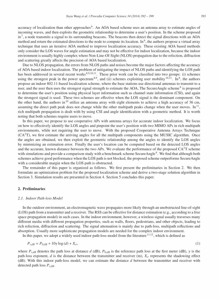
Fig. 1. A multipath element with AOA θm arriving at the K-elementantenna.
NLOS11θ
NLOS12θ
NLOS21θ
NLOS22θ
LOS1θ
LOS2θ
Fig. 2. A typical scenario of indoor localization where the LOS com-ponents are blocked by a wall.
2.2. AOA Estimation with MUSIC
We next briefly review the well-known Multiple Signal Classifier (MUSIC) scheme for AOA estimation13. Con-sider a K-element linear antenna array, which receives M multipath signals from a narrowband transmitter (such as aWi-Fi station) in an indoor environment. The signal sm (t − βm), for m = 1, · · · ,M, which arrives at the antenna arrayfrom direction θm with the propagation delay βm at time t, is assumed to be a plane wave due to the far-field model, asshown in Fig. 1. The received signal can be expressed by a K × 1 complex vector as13
�x(t) =M∑
m=1
�a(θm) · sm(t − βm) + �n(t) = A · �s(t) + �n(t), (2)
where �a(θm) is the K × 1 steering vector for the mth multipath component defined as �a(θm) = [1, exp(− j 2πλδ sin θm),
exp(− j 2πλ
2δ sin θm), · · · , exp(− j 2πλ
(K −1)δ sin θm)]T , δ is the distance between two neighboring antenna elements, andλ is the wavelength of the source signal; A =
[�a(θ1), �a(θ2), · · · , �a(θM)
]; �s(t) =
[s1(t − β1), s2(t − β2), · · · , sM(t − βM)
]T ;and �n (t) is the K ×1 noise vector. In the indoor environment, the difference in propagation delays for the narrow-bandmultipath signals is usually negligibly due to small distances. We therefore assume that βm ≈ 0, for all m, as in priorwork10 in the remaining part of this paper. It follows that �s(t) ≈ [s1(t), s2(t), · · · , sM(t)]T .
In order to analyze the incoming waves, the data correlation matrix Rxx can be derived as
Rxx = E[�x(t) · �x(t)H
]= E[(
A · �s (t) + �n (t))·(A · �s (t) + �n (t)
)H]= ARssAH + σ2
nI. (3)
In a real wireless system, it is not feasible to obtain Rxx due to the realtime constraint. However, the ensembleaverage R̂xx, computed as R̂xx =
1N
∑Nt=1 �x(t) · �x(t)H , can be used to approximate Rxx when the number of snapshots
N is sufficiently large, due to the ergodicity hypothesis. In addition, the ensemble average R̂xx can be decomposedinto the orthogonal signal subspace and noise subspace with eigenvalue decomposition (EVD)13, denoted as R̂xx =
ESΛSESH+ENΛNEN
H , where ES and EN are the signal subspace eigenvectors and the noise subspace eigenevectors ofR̂xx, respectively, andΛS andΛN are the signal subspace eigenvalues and the noise subspace eigenvalues, respectively.Since the signal subspace is orthogonal to the noise subspace, we can estimate the angles of the multipath waves bysearching for the peaks of the power spectrum function, which is given by13
P (θ) =�aH (θ)�a (θ)
�aH (θ) ENENH�a (θ)
. (4)
3. Indoor Localization with Cooperative Antenna Arrays
3.1. LOS Identification and Localization
From the power spectrum function P (θ), we can identify the angles of the multiple signal paths, including thedirect path, which is indicative of the distance, and the reflected paths. How to identify the direct path angle among

395 Xuyu Wang et al. / Procedia Computer Science 34 ( 2014 ) 392 – 399
many incoming angles is an important problem, because the result will determine the precision of the AOA basedlocalization. Most of the prior papers, such as SecureAngle9, assume that the strongest peak of the power spectrumcorresponds to the direct path. In fact, this assumption is true if the direct path is not blocked. However, in indoorenvironments, the direct path is usually obstructed; some reflected paths may have stronger peaks than the direct path.In such cases, there will be large localization errors with the existing techniques.
In this paper, we consider using two collaborative APs for identifying the direct path (or, the LOS) angle in richmultipath environments. An example is given in Fig. 2, where AP1 receives three signals with arriving angles θLOS 1,θNLOS 11, and θNLOS 21, and AP2 receives three signals with arriving angles θLOS 2, θNLOS 12 and θNLOS 22. Note that unlikeFig. 1, these angles are between the incoming path and the x-axis. Both direct paths, i.e., θLOS 1 and θLOS 2, are blockedby the wall. If a traditional scheme is used to identify the strongest peak of the power spectrum as in MUSIC, it willhighly likely ignore the two direct paths, which have weaker peaks in the power spectrum due to the effect of the wall.As a result, there will be large localization errors.
With collaborative APs, every AP with an antenna array can first estimate its incoming angles based on the MUSICalgorithm. We can then identify the LOS components based on the geometric relationship among the angles, as
Δθ = θLOS 2 − θLOS 1. (5)
In addition, Δθ can be estimated by the following equation as
Δθ = arccos((d2
1u + d22u − d2
12)/(2d1ud2u)), (6)
where d1u is the distance between AP1 and the user, d2u is the distance between AP2 and the user, and d12 is thedistance between AP1 and AP2. The AP–user distances can be estimated as d1u = 10(Pr1,dB−P0,dB)/(10γ) and d2u =
10(Pr2,dB−P0,dB)/(10γ), respectively, based on the propagation model (1).Once the LOS angles θLOS 1 and θLOS 2 are determined, we then use them to pinpoint the user’s location. Let (x1, y1)
be the coordinates of AP1, (x2, y2) the coordinates of AP2, and (xu, yu) the coordinates of the user. It can be seen thatthe two LOS angles satisfy equations tan(θLOS 1) = (yu − y1)/(xu − x1) and tan(θLOS 2) = (yu − y2)/(xu − x2). The user’slocation can be computed by solving these two equations, as
xu = (x1 tan(θLOS 1) − x2 tan(θLOS 2) + y2 − y1)/(tan(θLOS 1) − tan(θLOS 2)) (7)
yu = ((x1 − x2) tan(θLOS 1) tan(θLOS 2) + y2 tan(θLOS 1) − y1 tan(θLOS 2))/(tan(θLOS 1) − tan(θLOS 2)). (8)
Among the three distances, d1u and d2u are not accurate since they are estimated using the indoor path-loss model,while d12 is precisely known. By exploiting the cooperative APs, the LOS components can be identified more ac-curately. This is because except for the two LOS angles, the other reflected path angles are less likely to satisfy therelationship (5), due to the random reflections in the rich multipath environment. The main difference between thiswork and CUPID11 is that we use two APs to cooperatively identify the LOS components based on two crude distanceestimates d1u and d2u, as well as one accurate distance d12, and then use the two accurate LOS angles to pinpoint theuser’s position. In CUPID, only one AP is utilized to identify the LOS component based on three crude distanceestimates. CUPID then estimates the user’s location based on one accurate LOS angle and one crude AP–user range.Thus, the proposed scheme can achieve a better performance over CUPID in LOS identification.
3.2. Optimal LOS Angle Identification
We next show how to identify the LOS angles with the two cooperative APs. Since the estimated distances betweenthe APs and the user are not precise, equation (5) only holds true approximately. In other words, the estimation error| θLOS 2 − θLOS 1 − Δθ | is not always zero. The idea is to minimize this error term among all the identified incomingangles with MUSIC, while the minimizer yields the LOS angles.
Let Θ1 = {θ11, θ12, · · · , θ1m} be the set of arriving angles to AP1, and Θ2 = {θ21, θ22, · · · , θ2n} the set of arrivingangles to AP2 identified by MUSIC. As discussed, the sets of angles can be detected by finding the peaks in the powerspectrum function. Define index variables x1 j and x2k as follows: x1 j = 1 if θ1 j is the LOS component at AP1, andx1 j = 0 otherwise, for j = 1, 2, · · · ,m; x2k = 1 if θ2k is the LOS component at AP2, and x2k = 0 otherwise, fork = 1, 2, · · · , n. Since each AP can have only one LOS angle, we have constraints
∑mj=1 x1 j = 1 and
∑nk=1 x2k = 1. We

396 Xuyu Wang et al. / Procedia Computer Science 34 ( 2014 ) 392 – 399
then formulate the LOS identification problem as follows.
minimize
∣∣∣∣∣∣∣∣n∑
k=1, θ2k∈Θ2
x2k · θ2k −
m∑j=1, θ1 j∈Θ1
x1 j · θ1 j − Δθ
∣∣∣∣∣∣∣∣ (9)
subject to: Θ1 =
{θ
∣∣∣∣∣∣ arg maxθ
{P1(θ)} , P1(θ) =�a1(θ)H�a1(θ)
�a1(θ)HEN1EN1H�a1(θ)
}(10)
Θ2 =
{θ
∣∣∣∣∣∣ arg maxθ
{P2(θ)} , P2(θ) =�a2(θ)H�a2(θ)
�a2(θ)HEN1EN2H�a2(θ)
}(11)
d1u = 10(Pr1,dB−P0,dB)/(10γ) (12)
d2u = 10(Pr2,dB−P0,dB)/(10γ) (13)
Δθ = arccos((d2
1u + d22u − d2
12)/(2d1ud2u))
(14)m∑
j=1
x1 j = 1 (15)
n∑k=1
x2k = 1 (16)
x1 j ∈ {0, 1} , for j = 1, 2, · · · ,m, x2k ∈ {0, 1} , for k = 1, 2, · · · , n, (17)
where P1 (P2) denotes the power spectrum function of AP1 (AP2), �a1 (θ) (�a2 (θ)) is the steering vector of AP1 (AP2),EN1 (EN2) are the noise subspace eigenvectors of AP1 (AP2), and Θ1 (Θ2) is the set of angles that are the localmaximizers of the power spectrum function P1 (P1(θ)). The formulated problem is a non-linear integer programmingproblem, which is NP-hard. To reduce the computational complexity, we next show how to decompose it into twosub-problems in the following.
3.3. Two-Stage Algorithm
To solve the formulated optimal LOS angle identification problem, we decompose it into two sub-problems: (i)angle estimation and (ii) LOS angle identification. We first utilize MUSIC to estimate the incoming directions bysearching for the peaks of the power spectrum. Once the incoming angle sets are computed, the LOS angles can beselected by solving the reduced problem.
3.3.1. Angle EstimationWe first use MUSIC to estimate all the arriving angles at the two APs. The distance between two neighboring
antenna elements is half of the carrier wavelength. For angle estimation, we compute the data correlation matrix R̂xx
based on received signals. Then by decomposing R̂xx into the signal subspace and the noise subspace, we obtain thepower spectrum function. To obtain the set of arriving angles at the APs, we use (10) and (11) to find all the peaksin their power spectrum function. Since it is difficult to obtain closed-form expressions for Θ1 and Θ2 by maximizingthe power spectrum functions, we adopt an approximation method to find all the maximal value points in the powerspectrum function, by exploiting the fact that every peak point is greater than the values in its neighborhood.
We also use (12), (13), and (14) to estimate the angle between the two LOS paths. In fact, we need to obtain theAP–user distances with the maximum likelihood (ML) estimation method14 to overcome the shadowing and multipatheffects. Moreover, the RSS of every AP is the superposition of powers of all arriving signals. Traditionally, RSS can beused to estimate the AP–user distance by minimizing the sum square error between the measured RSS and estimatedRSS with the ML method. Thus d1u can be estimated as d1u = arg mind ‖Pr1,dB − P0,dB − 10γ log (d) ‖2, and d2u canbe estimated as d2u = arg mind ‖Pr2,dB − P0,dB − 10γ log (d) ‖2. The angle estimation algorithm as described above ispresented in Algorithm 1.
397 Xuyu Wang et al. / Procedia Computer Science 34 ( 2014 ) 392 – 399
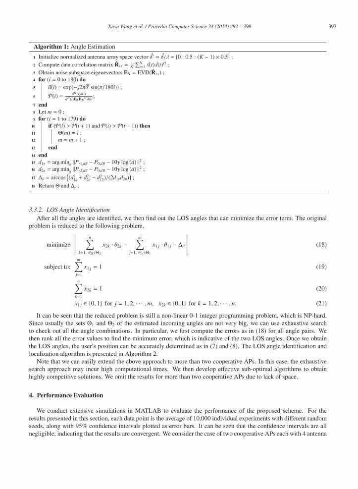
Algorithm 1: Angle Estimation
1 Initialize normalized antenna array space vector �δ′ = �δ/λ = [0 : 0.5 : (K − 1) × 0.5] ;2 Compute data correlation matrix R̂xx =
1N
∑Nt=1 �x(t)�x(t)H ;
3 Obtain noise subspace eigenevectors EN = EVD(R̂xx) ;4 for (i = 0 to 180) do5 �a(i) = exp(− j2π�δ′ sin(π/180i)) ;
6 P(i) = �aH (i)�a(i)�aH (i)ENEN
H�a(i);
7 end8 Let m = 0 ;9 for (i = 1 to 179) do
10 if (P(i) > P(i + 1) and P(i) > P(i − 1)) then11 Θ(m) = i ;12 m = m + 1 ;13 end14 end15 d1u = arg mind ‖Pr1,dB − P0,dB − 10γ log (d) ‖2 ;16 d2u = arg mind ‖Pr2,dB − P0,dB − 10γ log (d) ‖2 ;
17 Δθ = arccos((d2
1u + d22u − d2
12)/(2d1ud2u))
;
18 Return Θ and Δθ ;
3.3.2. LOS Angle IdentificationAfter all the angles are identified, we then find out the LOS angles that can minimize the error term. The original
problem is reduced to the following problem.
minimize
∣∣∣∣∣∣∣∣n∑
k=1, θ2k∈Θ2
x2k · θ2k −
m∑j=1, θ1 j∈Θ1
x1 j · θ1 j − Δθ
∣∣∣∣∣∣∣∣ (18)
subject to:m∑
j=1
x1 j = 1 (19)
n∑k=1
x2k = 1 (20)
x1 j ∈ {0, 1} for j = 1, 2, · · · ,m, x2k ∈ {0, 1} for k = 1, 2, · · · , n. (21)
It can be seen that the reduced problem is still a non-linear 0-1 integer programming problem, which is NP-hard.Since usually the sets Θ1 and Θ2 of the estimated incoming angles are not very big, we can use exhaustive searchto check out all the angle combinations. In particular, we first compute the errors as in (18) for all angle pairs. Wethen rank all the error values to find the minimum error, which is indicative of the two LOS angles. Once we obtainthe LOS angles, the user’s position can be accurately determined as in (7) and (8). The LOS angle identification andlocalization algorithm is presented in Algorithm 2.
Note that we can easily extend the above approach to more than two cooperative APs. In this case, the exhaustivesearch approach may incur high computational times. We then develop effective sub-optimal algorithms to obtainhighly competitive solutions. We omit the results for more than two cooperative APs due to lack of space.
4. Performance Evaluation
We conduct extensive simulations in MATLAB to evaluate the performance of the proposed scheme. For theresults presented in this section, each data point is the average of 10,000 individual experiments with different randomseeds, along with 95% confidence intervals plotted as error bars. It can be seen that the confidence intervals are allnegligible, indicating that the results are convergent. We consider the case of two cooperative APs each with 4 antenna

398 Xuyu Wang et al. / Procedia Computer Science 34 ( 2014 ) 392 – 399
Algorithm 2: LOS Angle Identification and Localization
1 Execute Algorithm 1 to obtain Θ1, Θ2, and Δθ ;
2 Let �dc be an m × n vector and set k = 1 ;3 for (i = 1 : m) do4 for ( j = 1 : n) do5 �dc(k) = | Θ2(i) − Θ1( j) − Δθ | ;6 k = k + 1; ;7 end8 end
9 Get the index of the minimum error p = arg min(�dc) ;10 Get LOS1=Θ1(�p/n), LOS2=Θ2(mod(p, n)) ;11 Determine the user’s position (xu, yu) according to (7) and (8) ;
0 10 20 30 40 50 60 70 80 90 1000
0.2
0.4
0.6
0.8
1
CD
F
AOA Error (o)
LOS1, Proposed schemeLOS1, SecureAngleLOS2, Proposed schemeLOS2, SecureAngle
Fig. 3. Angle estimation in unobstructed LOS environments.
0 10 20 30 40 50 60 70 80 90 1000
0.2
0.4
0.6
0.8
1
CD
F
Localization Error (cm)
Proposed schemeSecureAngle
Fig. 4. Localization in unobstructed LOS environments.
0 10 20 30 40 50 60 70 80 90 1000
0.2
0.4
0.6
0.8
1
CD
F
AOA Error (o)
LOS1, Proposed schemeLOS1, SecureAngleLOS2, Proposed schemeLOS2, SecureAngle
Fig. 5. Angle estimation in obstructed LOS environments.
0 10 20 30 40 50 60 70 80 90 1000
0.2
0.4
0.6
0.8
1
Localization Error (cm)
CD
F
Proposed scheme SecureAngle
Fig. 6. Localization in obstructed LOS environments.
elements, one located at (0, 0) and the other at (500 cm, 0). In addition, we assume that AP1 receives three incomingwaves with arriving angles [0, 30, 60], respectively, and AP2 receives three incoming waves with angles [35, 15,−30],respectively. We compare the proposed scheme with the SecureAngle method9 in the following two experiments.
In the first experiment, we consider the case that the LOS path is not blocked. The simulation results on angleestimation and localization are presented in Figs. 3 and 4, respectively. In the simulations, the SNRs of the receivedsignals at the two APs are 5 dB, the LOS signal strength is 17 dB higher than the other incoming waves, the number ofsnapshots N is 512, and the path-loss exponent γ is 2.0. It can be seen from Fig. 3 that both schemes perform well onidentifying the LOS angle in this scenario. However, with the proposed method, the cumulative distribution function

399 Xuyu Wang et al. / Procedia Computer Science 34 ( 2014 ) 392 – 399
(CDF) approaches 97% when the angle error is over 5◦. With SecureAngle, the CDF approaches 97% when the angleerror is in the range of 30◦ to 40◦. Similarly, from Fig. 4, we find that the localization error of the proposed method isabout 55 cm when the CDF reaches 93%. With SecureAngle, the error is 55 cm when the CDF exceeds 75%. Bothmethods achieve fine localization precisions in unobstructed indoor environments.
In the second scenario, the LOS path is blocked by a wall. The angle estimation and localization results arepresented in Figs. 5 and 6, respectively. In these simulations, the LOS signal strength is 5 dB lower than the otherincoming waves, the path-loss exponent γ is 3.3, and all the other parameters are the same as that in the previousscenario. It can be seen that the proposed scheme still performs well in the obstructed scenario. With the proposedscheme, the CDF of angle estimation approaches 97% when the angle error is above 5◦ and the localization CDF isover 97% when the error is above 50 cm. On the other hand, SecureAngle does not perform well in the obstructedscenario, as indicated by the large AOA and localization errors. Apparently, using the strongest peak of the powerspectrum leads to wrong LOS angle selections and large localization error in this case.
5. Conclusion
In this paper, we consider the problem of indoor localization in rich multipath environments. We propose to adopttwo cooperative APs with antenna arrays to improve the precision of LOS angle identification. The proposed schemeis based on the traditional MUSIC algorithm to identify the multipath angles. It then exploits the simple geometricrelationship among the multiple angles and the accurate distance between the two APs to accurately identify theLOS angles, leading to accurate localization for the user. The proposed scheme is validated with simulations andoutperforms an benchmark scheme with considerable gains, especially when the LOS path is blocked.
Acknowledgements
This work is supported in part by Cisco Systems, Inc., and by the US NSF under grant CNS-1247955 and the NSFI/UCRC Broadband Wireless Access & Applications Center (BWAC) site at Auburn University.
References
1. H. Liu, H. Darabi, P. Banerjee, and J. Liu, “Survey of wireless indoor positioning techniques and systems,” IEEE Trans. Syst., Man, Cybern.C, vol. 37, no. 6, pp. 1067–1080, Nov. 2007.
2. D. Niculescu and B. Nath,“Ad hoc positioning system (APS) using AOA,” in Proc. IEEE INFOCOM’03, San Francisco, CA, Mar./Apr. 2003,pp. 1734–1743.
3. M. Kanaan and K. Pahlavan,“A comparison of wireless geolocation algorithms in the indoor environment,” in Proc. IEEE WCNC’04, Atlanta,GA, Mar. 2004, pp. 177–182.
4. Y. T. Chan and K. C. Ho,“A simple and efficient estimator for hyperbolic location,”IEEE Trans. Signal Process., vol. 42, no. 8, pp. 1905–1915,Aug. 1994.
5. L. Cong and W. Zhuang,“Hybrid TDOA/AOA mobile user location for wideband CDMA cellular systems,”IEEE Trans. Wireless Commun.,vol. 1, no. 3, pp. 439–447, July 2002.
6. S. Kawakami and T. Ohtsuki, “Localization using iterative angle of arrival method sharing snapshots of coherent subarrays,” EURASIP J.Adv. Signal Process., vol. 2011, no. 46, 2011.
7. Z. Shan and T. S. P. Yum, “Precise localization with smart antennas in ad-hoc networks,” in Proc. IEEE GLOBECOM’07, Washington, DC,Nov. 2007, pp. 1053–1057.
8. D. Niculescu and B. Nath, “VOR base stations for indoor 802.11 positioning,” in Proc. ACM MobiCom’04, Philadelphia, PA, Sept. 2004,pp. 58–69.
9. J. Xiong and K. Jamieson, “SecureAngle: Improving wireless security using angle-of-arrival information,” in Proc. ACM HotNets’10, Mon-terey, CA, Oct. 2010, pp. 415–416.
10. J. Xiong and K. Jamieson, “ArrayTrack: A fine-grained indoor location system,” in Proc. USENIX NSDI’13, Lombard, IL, Apr. 2013,pp. 71–84.
11. S. Sen, J. Lee, K. H. Kim, and P. Congdon, “Avoiding multipath to revive inbuilding WiFi localization,” in Proc. ACM MobiSys’13, Taipei,Taiwan, June 2013, pp. 249–262.
12. T. S. Rappaport. Wireless Communications: Principles and Practice (2nd Edition). Prentice Hall: Upper Saddle River, NJ, 2002.13. R. Schmidt, “Multiple emitter location and signal parameter estimation,” IEEE Trans. Antennas Propag., vol. 34, no. 3, pp. 276–280, Mar.
1986.14. A. Coluccia and F. Ricciato, “On ML estimation for automatic RSS-based indoor localization,” in Proc. ISWPC’10, Modena, Italy, May.
2010, pp. 495–502.