ca10s, ca14 and ca14s air and gas traps - spirax · pdf fileim-p148-13 st issue 9 7 2. general...
TRANSCRIPT

IM-P148-13 ST Issue 9 1
CA10S, CA14 and CA14S Air and Gas Traps
Installation and Maintenance Instructions
1. Safety information
2. General product information
3. Installation
4. Commissioning
5. Operation
6. Maintenance and Spare parts
IM-P148-13ST Issue 9
1448150/9
© Copyright 2015
Printed in GB

IM-P148-13 ST Issue 92
Safe operation of these products can only be guaranteed if they are properly installed, commissioned, used and maintained by qualified personnel (see Section 11 within this document) in compliance with the operating instructions. General installation and safety instructions for pipeline and plant construction, as well as the proper use of tools and safety equipment must also be complied with.
1.1 Intended useReferring to the Installation and Maintenance Instructions, name-plate and Technical Information Sheet, check that the product is suitable for the intended use / application. The products listed below comply with the requirements of the European Pressure Equipment Directive 97 / 23 / EC and carry the mark when so required. The products fall within the following Pressure Equipment Directive categories:
Product Group 1 Gases
Group 2 Gases
Group 1Liquids
Group 2 Liquids
CA10S SEP SEP SEP SEP
CA14/CA14SDN15 - 20 SEP SEP SEP SEP
DN25 - 50 1 SEP SEP SEP
i) The products have been specifically designed for use on steam, air or water /condensate which are in Group 2 of the above mentioned Pressure Equipment Directive. The products’ use on other fluids may be possible but, if this is contemplated, Spirax Sarco should be contacted to confirm the suitability of the product for the application being considered.
ii) Check material suitability, pressure and temperature and their maximum and minimum values. If the maximum operating limits of the product are lower than those of the system in which it is being fitted, or if malfunction of the product could result in a dangerous overpressure or overtemperature occurrence, ensure a safety device is included in the system to prevent such over-limit situations.
iii) Determine the correct installation situation and direction of fluid flow.
iv) Spirax Sarco products are not intended to withstand external stresses that may be induced by any system to which they are fitted. It is the responsibility of the installer to consider these stresses and take adequate precautions to minimise them.
v) Remove protection covers from all connections before installation.
1.2 AccessEnsure safe access and if necessary a safe working platform (suitably guarded) before attempting to work on the product. Arrange suitable lifting gear if required.
1.3 LightingEnsure adequate lighting, particularly where detailed or intricate work is required.
1.4 Hazardous liquids or gases in the pipelineConsider what is in the pipeline or what may have been in the pipeline at some previous time. Consider: flammable materials, substances hazardous to health, extremes of temperature.
1. Safety information

IM-P148-13 ST Issue 9 3
1.5 Hazardous environment around the productConsider: explosion risk areas, lack of oxygen (e.g. tanks, pits), dangerous gases, extremes of temperature, hot surfaces, fire hazard (e.g. during welding), excessive noise, moving machinery.
1.6 The systemConsider the effect on the complete system of the work proposed. Will any proposed action (e.g. closing isolation valves, electrical isolation) put any other part of the system or any personnel at risk? Dangers might include isolation of vents or protective devices or the rendering ineffective of controls or alarms. Ensure isolation valves are turned on and off in a gradual way to avoid system shocks.
1.7 Pressure systems Ensure that any pressure is isolated and safely vented to atmospheric pressure. Consider double isolation (double block and bleed) and the locking or labelling of closed valves. Do not assume that the system has depressurised even when the pressure gauge indicates zero.
1.8 TemperatureAllow time for temperature to normalise after isolation to avoid danger of burns.
1.9 Tools and consumablesBefore starting work ensure that you have suitable tools and / or consumables available. Use only genuine Spirax Sarco replacement parts.
1.10 Protective clothingConsider whether you and / or others in the vicinity require any protective clothing to protect against the hazards of, for example, chemicals, high / low temperature, radiation, noise, falling objects, and dangers to eyes and face.
1.11 Permits to workAll work must be carried out or be supervised by a suitably competent person.Installation and operating personnel should be trained in the correct use of the product according to the Installation and Maintenance Instructions.Where a formal 'permit to work' system is in force it must be complied with. Where there is no such system, it is recommended that a responsible person should know what work is going on and, where necessary, arrange to have an assistant whose primary responsibility is safety.Post 'warning notices' if necessary.
1.12 HandlingManual handling of large and / or heavy products may present a risk of injury. Lifting, pushing, pulling, carrying or supporting a load by bodily force can cause injury particularly to the back. You are advised to assess the risks taking into account the task, the individual, the load and the working environment and use the appropriate handling method depending on the circumstances of the work being done.

IM-P148-13 ST Issue 94
Cast Iron is a brittle material. If the product is dropped during installation and there is any risk of damage the product should not be used unless it is fully inspected and pressure tested by the manufacturer.
Safe Handling
1.13 Residual hazardsIn normal use the external surface of the product may be very hot. If used at the maximum permitted operating conditions the surface temperature of some products may reach temperatures in excess of 500°C (932°F).Many products are not self-draining. Take due care when dismantling or removing the product from an installation (refer to 'Maintenance instructions').
1.14 FreezingProvision must be made to protect products which are not self-draining against frost damage in environments where they may be exposed to temperatures below freezing point.
1.15 Safety informationSee the relevant Sections of the attached Installation and Maintenance Instructions for specific details relating to these products.
1.16 DisposalUnless otherwise stated in the Installation and Maintenance Instructions, this product is recyclable and no ecological hazard is anticipated with its disposal providing due care is taken.
1.17 Returning productsCustomers and stockists are reminded that under EC Health, Safety and Environment Law, when returning products to Spirax Sarco they must provide information on any hazards and the precautions to be taken due to contamination residues or mechanical damage which may present a health, safety or environmental risk. This information must be provided in writing including Health and Safety data sheets relating to any substances identified as hazardous or potentially hazardous.
1.18 Working safely with cast iron products on steamCast iron products are commonly found on steam and condensate systems. If installed correctly using good steam engineering practices, it is perfectly safe. However, because of its mechanical properties, it is less forgiving compared to other materials such as SG iron or carbon steel. The following are the good engineer ing prac t ices requi red to prevent waterhammer and ensure safe working conditions on a steam system.

IM-P148-13 ST Issue 9 5
SteamTrap set
Trap setTrap set
SteamGradient 1:100
Gradient 1:100
30 - 50 metre intervals
CondensateCondensate
Condensate
Prevention of water hammer Steam trapping on steam mains:
Steam Mains - Do's and Don'ts:
Steam
Steam
Flow Flow
IM-P148-13 ST Issue 96
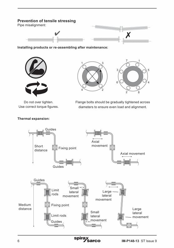
Prevention of tensile stressing Pipe misalignment:
Installing products or re-assembling after maintenance:
Thermal expansion:
Do not over tighten.Use correct torque figures.
11
4 2
3
82
6
3
7
Flange bolts should be gradually tightened across diameters to ensure even load and alignment.
Guides
Guides
Limit rods
Limit rods
Fixing pointMediumdistance
Small lateral
movement
Small lateralmovement
Large lateralmovement
Large lateral
movement
Shortdistance Fixing point
Axial movement
Axial movement
Guides
Guides
5
4

IM-P148-13 ST Issue 9 7
2. General product information
2.1 General description CA10S (¾" screwed)The CA10S is a float type automatic liquid drain trap for air and gas systems. It has a cast iron body and cover with stainless steel valve head for use on high temperature or where corrosive condensate would adversely affect a rubber valve.
CA14 and CA14S (½" and ¾" screwed and DN15, DN20 and DN25 flanged)The CA14 is a range of float type automatic liquid drainers for air systems. The body and cover are of SG iron and the complete unit is readily maintainable.The standard version has a Viton valve cone, designated CA14. A stainless steel valve cone version is also available, designated CA14S.
(DN15, DN20 and DN25 flanged only)The cover will be drilled and tapped ½" BSP or NPT for the purpose of fitting a balance line.Both flanged versions are available with horizontal flanged connections with flow from right to left CA14 (R-L) or from left to right CA14 (L-R).
CA14S (DN40 and 50 flanged)The CA14S is a cast iron ball float air and gas trap. It is available with a stainless steel valve cone given designation CA14S having horizontal flanged connections. The cover will be drilled and tapped ½" BSP or NPT for the purpose of fitting a balance line.
Optional on all unitsDrain cock tapping: The cover can be drilled and tapped " BSP or NPT to enable a drain cock to be fitted.
Note: For additional information see the following Technical Information Sheets:
Product Connection Material Section TI reference
CA10S ¾" Screwed Cast iron Section 2.2 TI-P148-15
CA14 ½" and ¾" Screwed SG iron Section 2.3 TI-P148-36
CA14S ½" and ¾" Screwed SG iron Section 2.3 TI-P148-36
CA14 DN15, DN20 and DN25 Flanged SG iron Section 2.4 TI-P148-12
CA14S DN15, DN20 and DN25 Flanged SG iron Section 2.4 TI-P148-12
CA14S DN40 and DN50 Flanged Cast iron Section 2.5 TI-P148-35

IM-P148-13 ST Issue 98
2.2 CA10S - Cast iron
Sizes and pipe connections¾" screwed BSP (BS 21 parallel) or NPT. A ½" tapping is provided for a balance pipe.
Fig. 1 ¾" screwed BSP

IM-P148-13 ST Issue 9 9
The product must not be used in this region.
Body design conditions PN16
PMA Maximum allowable pressure @ 120°C (248°F) 16 bar g (232 psi g)
TMA Maximum allowable temperature 250°C (482°F)
Minimum allowable temperature 0°C (32°F)
PMO Maximum operating pressure @ 120°C (248°F) 16 bar g (232 psi g)
TMO Maximum operating temperature @ 12.1 bar g (174 psi g) 220°C (428°F)
Minimum operating temperature 0°C (32°F)
∆PMX
Maximum differential pressure bar, depending on the specific gravity of the liquid being drained:
Specific gravity 1.0 0.9 0.8 0.7 Min. 0.6
∆PMX bar 14.0 13.8 11.7 8.6 5.0
∆PMN Minimum differential pressure 0.1 bar
Designed for a maximum cold hydraulic test pressure of 24 bar g (348 psi g)
������
���
���
��
�� � � � � �� �� �� ��
� �� �� �� �� ��� ��� ��� ������ ��� ���
���
���
���
���
Tem
pera
ture
°C
Pressure bar g
Temperature °F
Pressure psi g
Pressure / temperature limits

IM-P148-13 ST Issue 910
2.3 CA14 and CA14S - SG iron
Sizes and pipe connections½" and ¾" screwed BSP or NPT.
Fig. 2 ½" screwed BSP

IM-P148-13 ST Issue 9 11
The product must not be used in this region.
A - J - C CA14 screwed BSP or NPT. B - F - C CA14S screwed BSP or NPT.
Body design conditions PN16
PMA Maximum allowable pressure @ 120°C (248°F) 16 bar g (232 psi g)
TMA Maximum allowable temperature 250°C (482°F)
Minimum allowable temperature 0°C (32°F)
PMO Maximum operating pressure @ 120°C (248°F) 16 bar g (232 psi g)
TMOMaximum operating temperature:
CA14 @ 14.7 bar g (213.15 psi g) 200°C (392°F)
CA14S @ 13.9 bar g (201.6 psi g) 250°C (482°F)
Minimum operating temperature 0°C (32°F)
∆PMX
Maximum differential pressure bar, depending on the specific gravity of the liquid being drained:
Specific gravity 1.0 0.9 0.8 0.7 Min. 0.6
∆PMX bar 14.0 14.0 14.0 9.0 5.0
∆PMN Minimum differential pressure 0.1 bar
Designed for a maximum cold hydraulic test pressure of: 24 bar g (348 psi g)
���
���
���
���
��
�� � � � � �� �� �� ��
� �� �� �� �� ��� ��� ��� ������ ��� ���
���
���
���
���
���
AB
JF
CTem
pera
ture
°C
Pressure bar g
Temperature °F
Pressure psi g
Pressure/temperature limits

IM-P148-13 ST Issue 912
2.4 CA14 and CA14S - SG iron
Fig. 3 DN20 flanged
Sizes and pipe connectionsDN15, DN20 and DN25 Standard flange EN 1092 PN16, ANSI 150 and JIS/KS 10.A ½" tapping is provided for a balance pipe.

IM-P148-13 ST Issue 9 13
��
��
���
���
���
���
� � � � �� �� �� ��
� �� �� �� �� ��� ��� ��� ������ ��� ���
���
���
���
���
���
A
G
B
The product must not be used in this region.
A - J - D CA14 flanged PN16A - K - G CA14 flanged JIS/KS 10A - H - D CA14 flanged ANSI 150B - C - D CA14S flanged PN16B - F - G CA14S flanged JIS/KS 10B - E - D CA14S flanged ANSI 150
Body design conditions PN16
PMA Maximum allowable pressure @ 120°C (248°F) 16 bar g (232 psi g)
TMA Maximum allowable temperature 250°C (482°F)
Minimum allowable temperature 0°C (32°F)
PMO Maximum operating pressure @ 120°C (248°F) 16 bar g (232 psi g)
TMO Maximum operating temperature:
CA14 @ 14.7 bar g (213.15 psi g) 200°C (392°F)
CA14S @ 13.9 bar g (201.6 psi g) 250°C (482°F)
Minimum operating temperature 0°C (32°F)
∆PMX
Maximum differential pressure bar, depending on the specific gravity of the liquid being drained:
Specific gravity 1.0 0.9 0.8 0.7 Min. 0.6
∆PMX bar 14.0 14.0 14.0 9.0 5.0
∆PMN Minimum differential pressure 0.1 bar
Designed for a maximum cold hydraulic test pressure of: 24 bar g (348 psi g)
D
F E CH JK
Tem
pera
ture
°C
Pressure bar g
Temperature °F
Pressure psi g
Pressure/temperature limits

IM-P148-13 ST Issue 914
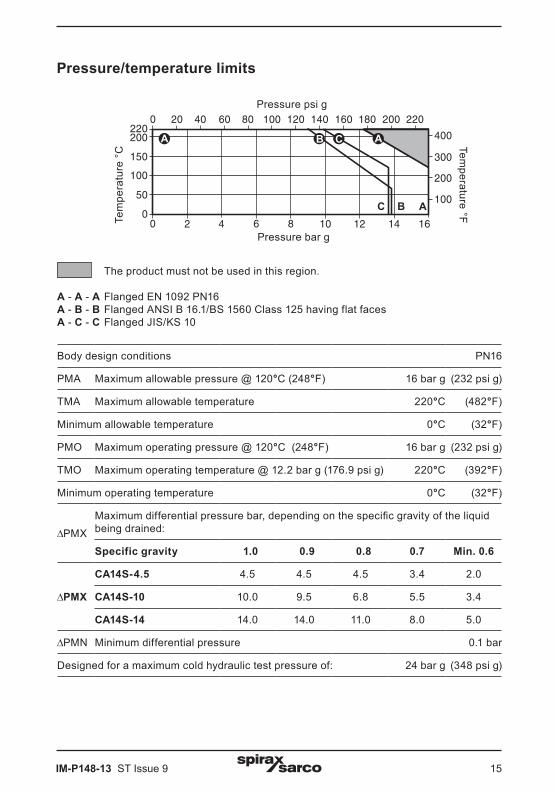
2.5 CA14S
Sizes and pipe connectionsDN40 and DN50. Standard flanges are EN 1092 PN16. On request ANSI B 16.1/ BS 1560 Class 125 and JIS/KS 10 flanges can be provided with drilled and tapped bolt holes. A ½" tapping is provided for a balance pipe.PN flanges will be provided with BSP balance line and ANSI, JIS/KS with NPT balance pipe.
Fig. 4 DN40 flanged
IM-P148-13 ST Issue 9 15
The product must not be used in this region.
A - A - A Flanged EN 1092 PN16A - B - B Flanged ANSI B 16.1/BS 1560 Class 125 having flat facesA - C - C Flanged JIS/KS 10
Body design conditions PN16
PMA Maximum allowable pressure @ 120°C (248°F) 16 bar g (232 psi g)
TMA Maximum allowable temperature 220°C (482°F)
Minimum allowable temperature 0°C (32°F)
PMO Maximum operating pressure @ 120°C (248°F) 16 bar g (232 psi g)
TMO Maximum operating temperature @ 12.2 bar g (176.9 psi g) 220°C (392°F)
Minimum operating temperature 0°C (32°F)
∆PMX
Maximum differential pressure bar, depending on the specific gravity of the liquid being drained:
Specific gravity 1.0 0.9 0.8 0.7 Min. 0.6
∆PMX
CA14S-4.5 4.5 4.5 4.5 3.4 2.0
CA14S-10 10.0 9.5 6.8 5.5 3.4
CA14S-14 14.0 14.0 11.0 8.0 5.0
∆PMN Minimum differential pressure 0.1 bar
Designed for a maximum cold hydraulic test pressure of: 24 bar g (348 psi g)
������
���
���
��
�� � � � � �� �� �� ��
� �� �� �� �� ��� ��� ��� ������ ��� ���
���
���
���
���
C AB
Tem
pera
ture
°C
Pressure bar g
Temperature °F
Pressure psi g
A B C A
Pressure/temperature limits

IM-P148-13 ST Issue 916
Note: Before actioning any installation observe the 'Safety information' in Section 1.
WarningThe cover gasket and the main valve assembly gasket on the CA14S contains a thin stainless steel support ring which may cause physical injury if not handled and disposed of carefully.
Referring to the Installation and Maintenance Instructions, name-plate and Technical Information Sheet, check that the product is suitable for the intended installation:
3.1 Check materials, pressure and temperature and their maximum values. If the maximum operating limit of the product is lower than that of the system in which it is being fitted, ensure that a safety device is included in the system to prevent overpressurisation.
3.2 Determine the correct installation situation and the direction of fluid flow.
3.3 Remove protective covers from all connections.
3.4 CA10S, CA14 and CA14S (½" and ¾" screwed) The trap should be fitted in the horizontal
plane with the inlet at the top so that the float mechanism is free to rise and fall in a vertical plane. Some typical installations are displayed in Figures 5, 6 and 7.
CA14 and CA14S (DN15, DN20, DN40 and DN50 flanged) The trap should be fitted in the horizontal
plane so that the float mechanism is free to rise and fall in a vertical plane. In this orientation the flow will be either left-to-right or right-to-left.
Note: Figure 5 shows an installation without balance line arrangement.
3.5 The trap must be fitted below what it is draining. Point the arrow on the name-plate downwards. One of the advantages of the float trap for draining air systems is that no air bleed is required for satisfactory operation. However, because the trap has no air bleed it could under some circumstances become air locked. If the load is low, i.e. mains drainage applications, then the air in the body can be displaced as water passes into it. However, if the load is high, i.e. after cooler or receiver drainage applications, then the air in the body cannot be displaced through the inlet pipe and a separate balance line is needed. It should be noted that the balance line is piped back to the upstream side. The need for a balance line to prevent the trap from air locking can only be decided by trial and error. If in any doubt it is preferable to use the balance line arrangement.
Note: If the trap is to discharge to atmosphere ensure it is to a safe place, the discharging fluid may be at a temperature of 100°C (212°F).
3. Installation
Fig. 5
M e t h o d o f draining the foot of rising pipe or relay drain in a horizontal run.
Strainer
CA14 air trap

IM-P148-13 ST Issue 9 17
Figs. 6 and 7 Installations with balance line arrangement
Fig. 6 Air trap draining a separator on a compressed air main
Separator
Balanceline
Strainer
CA14air trap
Fig. 7 Air trap draining a small receiver
Balanceline
StrainerCA14air trap
Air receiver
After installation or maintenance ensure that the system is fully functional. Carry out tests on any alarms or protective devices.
4. Commissioning
The CA10 and CA14 float trap is a continuous discharge trap, removing liquid from air and gas systems. As soon as liquid enters the main chamber of the trap, the float rises and the lever mechanism attached to it opens the main valve - keeping the system drained of liquid at all times. When air or gas arrives, the float drops and shuts the main valve tightly against the seat. The balance line is necessary to prevent the trap from becoming air locked. Float type traps are renowned for their instantaneous load handling capability, clean tight shut-off and resistance to waterhammer and vibration.
5. Operation

IM-P148-13 ST Issue 918
6. Maintenance and Spare parts
6.1 CA10S (¾" screwed)Note: Before actioning any maintenance program observe the 'Safety information' in Section 1.
WarningThe cover gasket contains a thin stainless steel support ring which may cause physical injury if not handled and disposed of carefully.
Servicing:- With suitable isolation, repairs can be carried out with the trap in the pipeline. - When reassembling, make sure that all joint faces are clean and the dowel locates in the cover.
How to fit the main valve assembly:- Isolate, undo cover bolts (2), remove existing mechanism (5, 6, 7, 8 + 12, 9, 10, 11). - Using a little jointing paste on the thread and gasket (6), fit the new valve seat to the body (5) and tighten to the recommended torque (see Table 1).- Attach the support frame (10), and pivot frame (11) to the body with assembly set screws (7), but do not tighten.- Fit the float arm (8 + 12) to the pivot frame (11) using the pin (9) and by moving the complete assembly centre the valve head onto the seat orifice. Hold the assembly firmly in place and tighten up set screws (7) to the recommended tightening torque (see Table 1).- Check operation by raising and lowering the float several times making sure that the valve head is centring properly on the seat.- Make sure all joint faces are clean, apply a thin coating of an anti-seize compound to the cover bolt threads (2).- Refit the cover (4) using a new cover gasket (3)- Tighten cover bolts (2) uniformly to the recommended tightening torque (see Table 1). Open up the isolating valve slowly until full system pressure is achieved. - Check for leaks.
Table 1 Recommended tightening torques Item or
mmN m (lbf ft)
2 Cover bolt 17 A/F M10 x 30 29 - 32 (19 - 23)
5 Valve seat 17 A/F M12 x 8 50 - 55 (37 - 40)
7 Pivot frame assembly set screws Cheesehead M5 x 20 2.5 - 2.8 (1.8 - 2.1)

IM-P148-13 ST Issue 9 19
Spare partsThe spare parts available are shown in heavy outline. Parts drawn in broken line are not supplied as spares.
Available sparesMain valve assembly with float 5, 6, 7, 8 +12, 9, 14, 15, 16
Gasket set (packet of 3 sets) 3, 6
How to order sparesAlways order spares by using the description given in the column headed 'Available spares' and state the size and type of trap.Example: 1 - Main valve assembly for a Spirax Sarco ¾" CA10S air and gas trap.
2 3 6 5 9 10 11 7 8 + 12
Main valve assembly with float
Fig. 8

IM-P148-13 ST Issue 920
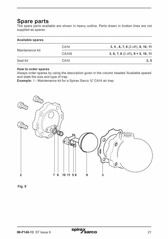
6.2 CA14 and CA14S (½" and ¾" screwed)Note: Before actioning any maintenance program observe the 'Safety information' in Section 1.
WarningThe cover gasket contains a thin stainless steel support ring which may cause physical injury if not handled and disposed of carefully.
Servicing:- With suitable isolation, repairs can be carried out with the trap in the pipeline. - When reassembling, make sure that all joint faces are clean.
How to fit the main valve CA14:- Undo the cover bolts (2) and lift off the cover (4), withdraw the pivot pin (11) to release the float and lever (9) from the pivot frame (10).- Push out the main valve cone (5) and replace with a new one.- Reassemble and refit the cover (4) using a new gasket (3).- Tighten cover bolts (2) uniformly to the recommended tightening torque (see Table 2). Open up the isolating valve slowly until full system pressure is achieved. - Check for leaks.
How to replace the main valve assembly CA14 and CA14S:- Undo the cover bolts (2) and lift off the cover (4).- Remove the complete float assembly (9, 10, 11 and 5) by undoing the two screws (8).- Remove the main valve seat (6) and replace with a new one supplied with new gasket (7).- Fit a complete new float assembly (9, 10, 11 and 5) by tightening the assembly set screws (8) to the recommended torque (see Table 2).- Refit the cover using a new gasket (3).- Tighten cover bolts (2) uniformly to the recommended tightening torque (see Table 2). Open up the isolating valve slowly until full system pressure is achieved. - Check for leaks.
Table 2 Recommended tightening torques Item or
mmN m (lbf ft)
2 Cover bolt 17 A/F M10 x 30 47 - 50 (35 - 37)
5 Valve seat 17 A/F M12 50 - 55 (36 - 40)
8 Pivot frame assembly set screws Pozidrive M4 x 6 2.5 - 3.0 (1.8 - 2.2)
IM-P148-13 ST Issue 9 21
Spare partsThe spare parts available are shown in heavy outline. Parts drawn in broken lines are not supplied as spares.
Available spares
Maintenance kitCA14 3, 5 , 6, 7, 8 (2 off), 9, 10, 11
CA14S 3, 6, 7, 8 (2 off), 9 + 5, 10, 11
Seal kit CA14 3, 5
How to order sparesAlways order spares by using the description given in the column headed 'Available spares' and state the size and type of trap.Example: 1 - Maintenance kit for a Spirax Sarco ½" CA14 air trap.
2 7 6 10 11 5 8 9 3
Fig. 9

IM-P148-13 ST Issue 922
6.3 CA14 and CA14S (DN15, 20 and 25 flanged)Note: Before actioning any maintenance program observe the 'Safety information' in Section 1.
WarningThe cover gasket contains a thin stainless steel support ring which may cause physical injury if not handled and disposed of carefully.
Servicing:- With suitable isolation, repairs can be carried out with the trap in the pipeline. - When reassembling, make sure that all joint faces are clean.
How to fit the main valve - CA14:- Undo the cover bolts (2) and lift off the cover (4), withdraw the pivot pin (11) to release the float and lever (9) from the pivot frame (10).- Push out the main valve cone (5) and replace with a new one.- Reassemble and refit the cover using a new gasket (3).- Tighten cover bolts (2) uniformly to the recommended tightening torque (see Table 3). Open up the isolating valve slowly until full system pressure is achieved. - Check for leaks.
How to fit the main valve assembly - CA14 and CA14S:- Undo the cover bolts (2) and lift off the cover (4).- Remove the complete float assembly (5, 9, 10, 11 and 13 DN25 only) by undoing the two screws (8).- Remove the main valve seat (6) and replace with a new one supplied with new gasket (7).- Fit complete new float assembly by tightening the assembly set screws (8) to the recommended torque (see Table 3).- Refit the cover (4) using a new gasket (3).- Tighten cover bolts (2) uniformly to the recommended tightening torque (see Table 3). Open up the isolating valve slowly until full system pressure is achieved. - Check for leaks.
Table 3 Recommended tightening torques
Item ormm N m (lbf ft)
2 Cover bolt 17 A/F M10 x 30 47 - 50 (35 - 37)
6 Valve seat 17 A/F M12 x 12 50 - 55 (36 - 40)
8 Pivot frame assembly set screws Pozidrive M4 x 6 2.5 - 3.0 (1.8 - 2.2)

IM-P148-13 ST Issue 9 23
Spare partsThe spare parts available are shown in heavy outline. Parts drawn in broken lines are not supplied as spares.
Available spares
Maintenance kit
CA14S 3, 6, 7, 8 (2 off), 5 + 9, 10, 11, 13 (DN25 only)
CA14 3, 6, 7, 8 (2 off), 5 + 9, 10, 11
Seal kit CA14 3, 5
How to order sparesAlways order spares by using the description given in the column headed 'Available spares' and state the size and type of trap.Example: 1 - Maintenance kit for a Spirax Sarco DN15 CA14 air and gas trap.
2 5 913811 1067
Main valve assembly Note: Item 13 is required for DN25 size only
3
Fig. 10

IM-P148-13 ST Issue 924
6.4 CA14S (DN40 and 50 flanged)Note: Before actioning any maintenance program observe the 'Safety information' in Section 1.
WarningThe cover gasket and main valve assembly gasket, contains a thin stainless steel support ring which may cause physical injury if not handled and disposed of carefully.
Servicing:- With suitable isolation, repairs can be carried out with the trap in the pipeline. - When reassembling, make sure that all joint faces are clean and the dowel locates in the cover.
How to fit the main valve assembly: - Undo the cover bolts (2) and lift off the cover.- Remove the complete float assembly (7, 8, 9, 10 and 11) by undoing the two screws (6).- Remove the main valve seat (5) and replace with a new one supplied with new gasket (14). Tighten to the recommended tightening torques (see Table 4).- Attach the support frame (9) and pivot frame (10) to the body with the assembly set screws (6), but do not tighten.- Fit the float arm (7 and 8) to the pivot frame (10) using the pin (11) and by moving the
complete assembly centre the valve head onto the seat orifice. Hold the assembly firmly in place and tighten up the set screws (6) to the recommended tightening torque (see Table 4).
- Check operation by raising and lowering the float (7) several times making sure that the valve head is centering properly on the seat (5).
- Make sure that all joint faces are clean and apply a thin coating of an anti-seize compound to the cover bolts (2).- Tighten cover bolts (2) uniformly to the recommended tightening torque (see Table 4). Open up the isolating valve slowly until full system pressure is achieved. - Check for leaks.
Table 4 Recommended tightening torques
Item Size Qty ormm N m (lbf ft)
2 Cover studsand nuts
DN40 6 19 A/F M12 60 - 66 (44 - 48)
DN50 6 24 A/F M16 80 - 88 (58 - 65)
5 Valve seat DN40, DN50 1 17 A/F M12 50 - 55 (37 - 40)
6 Pivot frameassembly bolts DN40, DN50 2 Cheesehead M5 x 20 25 - 28 (18 - 20)
13 Mounting platefastening bolts
DN40 4 10 A/F M6 10 - 12 (7 - 9)
DN50 4 13 A/F M8 20 - 24 (15 - 17)

IM-P148-13 ST Issue 9 25
72
Dowel2
3
1411
5 9
106
8
Main valve assemblywith float
13
Spare partsThe spare parts available are shown in heavy outline. Parts drawn in broken line are not supplied as spares.
Available sparesMain valve assembly with float* 5, 6, 7+8, 9, 10, 11, 14
* The erosion deflector is pressed into the body during manufacture and not available as a spare
Complete set of gaskets (packet of 3 sets) 3, 14
How to order sparesAlways order spares by using the description given in the column headed 'Available spares' and state the size and type of trap.Example: 1 - Main valve assembly with float for a Spirax Sarco DN40 CA14S-14 air and gas trap.
Fig. 11

IM-P148-13 ST Issue 926

IM-P148-13 ST Issue 9 27

IM-P148-13 ST Issue 928