ca gen gen 8 5-enu...converting c runtime to ibm c and using dlls in allfusion gen 7 enabled dynamic...
TRANSCRIPT
z/OS Implementation Toolset User Guide Release 8.5
CA Gen
Second Edition

This Documentation, which includes embedded help systems and electronically distributed materials (hereinafter referred to as the “Documentation”), is for your informational purposes only and is subject to change or withdrawal by CA at any time.
This Documentation may not be copied, transferred, reproduced, disclosed, modified or duplicated, in whole or in part, without the prior written consent of CA. This Documentation is confidential and proprietary information of CA and may not be disclosed by you or used for any purpose other than as may be permitted in (i) a separate agreement between you and CA governing your use of the CA software to which the Documentation relates; or (ii) a separate confidentiality agreement between you and CA.
Notwithstanding the foregoing, if you are a licensed user of the software product(s) addressed in the Documentation, you may print or otherwise make available a reasonable number of copies of the Documentation for internal use by you and your employees in connection with that software, provided that all CA copyright notices and legends are affixed to each reproduced copy.
The right to print or otherwise make available copies of the Documentation is limited to the period during which the applicable license for such software remains in full force and effect. Should the license terminate for any reason, it is your responsibility to certify in writing to CA that all copies and partial copies of the Documentation have been returned to CA or destroyed.
TO THE EXTENT PERMITTED BY APPLICABLE LAW, CA PROVIDES THIS DOCUMENTATION “AS IS” WITHOUT WARRANTY OF ANY KIND, INCLUDING WITHOUT LIMITATION, ANY IMPLIED WARRANTIES OF MERCHANTABILITY, FITNESS FOR A PARTICULAR PURPOSE, OR NONINFRINGEMENT. IN NO EVENT WILL CA BE LIABLE TO YOU OR ANY THIRD PARTY FOR ANY LOSS OR DAMAGE, DIRECT OR INDIRECT, FROM THE USE OF THIS DOCUMENTATION, INCLUDING WITHOUT LIMITATION, LOST PROFITS, LOST INVESTMENT, BUSINESS INTERRUPTION, GOODWILL, OR LOST DATA, EVEN IF CA IS EXPRESSLY ADVISED IN ADVANCE OF THE POSSIBILITY OF SUCH LOSS OR DAMAGE.
The use of any software product referenced in the Documentation is governed by the applicable license agreement and such license agreement is not modified in any way by the terms of this notice.
The manufacturer of this Documentation is CA.
Provided with “Restricted Rights.” Use, duplication or disclosure by the United States Government is subject to the restrictions set forth in FAR Sections 12.212, 52.227-14, and 52.227-19(c)(1) - (2) and DFARS Section 252.227-7014(b)(3), as applicable, or their successors.
Copyright © 2015 CA. All rights reserved. All trademarks, trade names, service marks, and logos referenced herein belong to their respective companies.

CA Technologies Product References
This document references the following CA Technologies products:
■ AllFusion Gen 7
■ AllFusion Gen 7.5
Contact CA Technologies
Contact CA Support
For your convenience, CA Technologies provides one site where you can access the information that you need for your Home Office, Small Business, and Enterprise CA Technologies products. At http://ca.com/support, you can access the following resources:
■ Online and telephone contact information for technical assistance and customer services
■ Information about user communities and forums
■ Product and documentation downloads
■ CA Support policies and guidelines
■ Other helpful resources appropriate for your product
Providing Feedback About Product Documentation
If you have comments or questions about CA Technologies product documentation, you can send a message to [email protected].
To provide feedback about CA Technologies product documentation, complete our short customer survey which is available on the CA Support website at http://ca.com/docs.


Contents 5
Contents
Chapter 1: z/OS Implementation Toolset 9
Runtime Changes ......................................................................................................................................................... 9
PDSEs ..................................................................................................................................................................... 9
C Runtime DLLs and Code Page Customization ................................................................................................... 10
LE Changes .......................................................................................................................................................... 10
Assembler and COBOL Runtime DLLs .................................................................................................................. 10
TSOAE .................................................................................................................................................................. 11
Application Migration ......................................................................................................................................... 11
z/OS Implementation Toolset Components ............................................................................................................... 11
Application Execution Facility ............................................................................................................................. 12
Installation Tool .................................................................................................................................................. 12
Application Test Facility ...................................................................................................................................... 13
Background Utility ............................................................................................................................................... 13
Runtime Routines ................................................................................................................................................ 13
Installation Process Overview .................................................................................................................................... 14
Load the Scripts ................................................................................................................................................... 14
Define the Target Configuration ......................................................................................................................... 14
Transfer Implementation Packages .................................................................................................................... 15
Complete the Construction of Code ................................................................................................................... 15
Chapter 2: Loading the Scripts 19
Introduction ............................................................................................................................................................... 19
Navigating Through the Toolset ................................................................................................................................. 20
What is a Script .......................................................................................................................................................... 21
Supplied Scripts .......................................................................................................................................................... 21
Before You Begin Loading Scripts ............................................................................................................................... 21
Loading Scripts ........................................................................................................................................................... 22
Viewing Scripts ........................................................................................................................................................... 23
Viewing Tokens .......................................................................................................................................................... 24
Chapter 3: Defining the Target Configuration 27
The Implementation Toolset ...................................................................................................................................... 27
Before You Begin ........................................................................................................................................................ 27
Target Definition ........................................................................................................................................................ 28
Add a Target ........................................................................................................................................................ 28
Duplicate a Target ............................................................................................................................................... 32

6 z/OS Implementation Toolset User Guide
Modify a Target ................................................................................................................................................... 32
Delete a Target .................................................................................................................................................... 34
Model Definition ........................................................................................................................................................ 34
Add a Model ........................................................................................................................................................ 35
Modify a Model ................................................................................................................................................... 35
Delete a Model .................................................................................................................................................... 37
Business System Definition ........................................................................................................................................ 37
Add a Business System ........................................................................................................................................ 38
Modify a Business System ................................................................................................................................... 39
Delete a Business System .................................................................................................................................... 40
Chapter 4: Creating an Application Database 43
Before You Begin ........................................................................................................................................................ 43
Process the DDL IP ...................................................................................................................................................... 43
Chapter 5: Processing the Cascade IP 45
Processing the Cascade IP .......................................................................................................................................... 45
Chapter 6: Creating Executable Load Modules 47
Process the Load Module IP ....................................................................................................................................... 48
Reinstalling a Load Module ........................................................................................................................................ 49
Chapter 7: Implementing External Action Blocks 51
Prerequisites .............................................................................................................................................................. 51
Terms .......................................................................................................................................................................... 52
Implementing External Action Blocks ........................................................................................................................ 53
Design ......................................................................................................................................................................... 54
Define an External Action Block .......................................................................................................................... 54
Create the Calling Procedure Step or Action Block ............................................................................................. 55
Construction ............................................................................................................................................................... 60
Environment ........................................................................................................................................................ 60
Packaging ............................................................................................................................................................ 60
Generation .......................................................................................................................................................... 61
Identify Whether the External Action Block Exists .............................................................................................. 62
Locate the External Action Block Stub ................................................................................................................ 62
Customize the Appropriate External Action Logic .............................................................................................. 63
Modifying the External Action Block Stub ........................................................................................................... 67
Compile the External Action Block ...................................................................................................................... 69
Installation .................................................................................................................................................................. 74

Contents 7
Transfer the Remote File ..................................................................................................................................... 74
Identify Whether the External Action Block Exists .............................................................................................. 75
Install the Load Module ...................................................................................................................................... 75
Chapter 8: Testing Applications 77
Application Test Facility Considerations .................................................................................................................... 77
CICS Debug Trace Facility Considerations .................................................................................................................. 78
Trace Facility Display Interface ................................................................................................................................... 78
Generate IPs for Testing ............................................................................................................................................. 79
Generate with Debug Support ............................................................................................................................ 79
Install in the Test Environment .................................................................................................................................. 79
Application Test Facility ...................................................................................................................................... 79
CICS Testing ......................................................................................................................................................... 80
Create the Executable ......................................................................................................................................... 80
Execute Test Under CICS ............................................................................................................................................ 80
CICS DTF User Interface ...................................................................................................................................... 80
DTF Error Codes .................................................................................................................................................. 82
Execute Test Under the Application Test Facility ....................................................................................................... 83
Specify the Test Execution Environment............................................................................................................. 83
DB2 Subsystem .................................................................................................................................................... 84
Application Load Library ..................................................................................................................................... 84
Begin Testing ....................................................................................................................................................... 84
Complete Testing and Return to CA Gen ............................................................................................................ 86
Abnormal Ends .................................................................................................................................................... 86
Debug Trace Facility ................................................................................................................................................... 88
Trace Action Block Calls ...................................................................................................................................... 88
Action Diagram Trace Panel ................................................................................................................................ 89
Making Changes to an Application ...................................................................................................................... 97
Common Testing Errors....................................................................................................................................... 97
Chapter 9: Background Utility 99
Provide Job Card Information .................................................................................................................................... 99
Build JCL Member ....................................................................................................................................................... 99
Provide the Name of the Target Definition ......................................................................................................... 99
Provide the List of Remote Files ........................................................................................................................ 100
Verify the Results of the Background Process .................................................................................................. 104
Submit ............................................................................................................................................................... 105
Chapter 10: Testing, Production, and Maintenance 109
Application Testing ................................................................................................................................................... 109

8 z/OS Implementation Toolset User Guide
Application Production ............................................................................................................................................. 110
Production in the IEFAE Environment ............................................................................................................... 110
Batch ................................................................................................................................................................. 110
Production in the CICS Environment ................................................................................................................. 111
Production in the IMS Environment .................................................................................................................. 111
Application Maintenance ......................................................................................................................................... 111
Application Migration............................................................................................................................................... 112
Migrating from CA Gen 8 .................................................................................................................................. 112
Migrating from Release 7.6 ............................................................................................................................... 112
Migrating from Allfusion Gen 7.5 ...................................................................................................................... 113
Migrating from Release 7 .................................................................................................................................. 113
Migrating from 6.5 and Earlier Releases ........................................................................................................... 114
EAB Migration ................................................................................................................................................... 115
z/OS Runtime User Exits .................................................................................................................................... 117
Load Module Packaging ........................................................................................................................................... 117
Chapter 11: Customizing Scripts and User Exits 119
Script Delimiters ....................................................................................................................................................... 119
Script Directives........................................................................................................................................................ 119
FOREACH,...ENDFOR ......................................................................................................................................... 120
OPENFILE,...CLOSEFILE ...................................................................................................................................... 120
Tokens ...................................................................................................................................................................... 120
Environment Parameter Tokens ....................................................................................................................... 121
Generalized Markup Language Tokens ............................................................................................................. 126
Modifying Tokens .............................................................................................................................................. 132
Customizing and Installing User Exits ................................................................................................................ 133
Chapter 12: Installing an Application on TSO 135
Moving a TSO Application ........................................................................................................................................ 135
Index 137
Chapter 1: z/OS Implementation Toolset 9
Chapter 1: z/OS Implementation Toolset
This article describes the tasks and procedures required to configure, use, and maintain the CA Gen Implementation Toolset (IT) on a z/OS platform. This information is intended for individuals that configure the Implementation Toolset on the target host, manage the target host test applications, and install the generated applications that execute in the z/OS host environment.
The CA Gen Implementation Toolset (or IT) supports the installation of COBOL-constructed applications that execute under z/OS accessing DB2 databases. References to DB2 in this guide refer to DB2 UDB for z/OS.
The information in this guide is intended for those with a working knowledge of and existing TSO/ISPF system data sets, and a basic understanding of programming and using model-based development tools.
Note: For additional information, see the Workstation Construction Guide.
Runtime Changes
CA Gen z/OS Runtime includes a multi-language execution environment made up of C, COBOL, and Assembler code. This section is an extract of the Release Summary documents since AllFusion Gen 7 that summarizes the z/OS Runtime changes in those releases.
PDSEs
The AllFusion Gen 7 runtimes were converted to Program Objects and must reside in a PDSE library, a data set type of LIBRARY. The installation jobs included with the Implementation Toolset create PDSE data sets for CA Gen CEHBPLD0 and CEHBPLD1 libraries.
Since the generated code also became Program Objects, when you use the Business System data sets specified for NCAL, Executable and RI Trigger Load modules and Compatibility libraries must be PDSEs. When you create CA Gen user exits using the DYNAM(DLL) option, the External System Load Libraries containing these user exit modules must also be PDSEs. When using the External Action Block and Compatibility External Action Block libraries, they must be PDSEs.

Runtime Changes
10 z/OS Implementation Toolset User Guide
C Runtime DLLs and Code Page Customization
The C runtimes were converted to IBM C and became LE conformant in AllFusion Gen 7. Since applications created by the releases of AllFusion Gen earlier than release 7 cannot use these new C runtime modules, CA Gen includes new runtimes, TIRCRUNC for CICS and TIRCRUNI for IMS.
User modifications to the code page translation routines require using the TIRCRUNC and TIRCRUNI Dynamic Runtime modules. CA Gen includes a sample utility, MKCRUN, to facilitate making user modifications to TIRCRUNC and TIRCRUNI. When using MKCRUN, if the TIRXINFO user exit is modified, the resulting TIRXINFZ DLL must also be deployed.
LE Changes
In AllFusion Gen 7.5, the z/OS runtime was updated to full IBM LE conformance. The runtimes use the standard LE call interface, which reduces the complexity of the runtime code. The runtimes are fully re-entrant and threadsafe, to enhance the reliability and performance of the runtime and the generated applications they support.
CA Gen runtimes exploit LE storage management within the assembler routines, eliminating the need to frequently call GETMAIN and FREEMAIN, reducing CPU usage for runtime modules in certain generated applications, such as batch jobs. CA Gen's C and COBOL runtimes changed to use similar functionality.
Migrating CA Gen's Assembler code to LE functionality decreased the number of OS storage calls, decreasing CPU use when a generated application invokes Assembler runtime functions. The benefit of this change depends on LE heap and stack settings and how each generated application uses these runtimes, as block mode, batch, or a distributed processing server.
Assembler and COBOL Runtime DLLs
Converting C runtime to IBM C and using DLLs in AllFusion Gen 7 enabled dynamic linking support to COBOL and Assembler AllFusion Gen runtimes. This was completed in AllFusion Gen 7.5.
CA Gen implements most Assembler and COBOL runtimes as DLLs. Since these runtimes are dynamically loaded, multiple processes share a single copy of the runtime, significantly decreasing the overall load module size for a CA Gen applications. AllFusion Gen 7.5 improved serviceability from earlier releases by letting you update the runtime without requiring statically linking the maintenance items into every generated application. Maintenance applied to a DLL is available to all generated applications that use the DLL.
z/OS Implementation Toolset Components
Chapter 1: z/OS Implementation Toolset 11
TSOAE
CA implemented the TSOAE environment used by the z/OS IT and the Application Test Facility as a 31-bit, LE-compliant application in AllFusion Gen 7.5. The use of 24-bit storage was changed to be limited to those TSO and I/O functions that require addressing below the 16-MB line. This version of TSOAE provides virtual storage constraint relief for testing and implementing large CA Gen applications within TSO and batch.
Application Migration
There are different application migration requirements depending on the CA Gen release that the application is migrating from and the type of linkage the application uses to invoke the various components of that application.
Note: For more information about Migration, see the Release Notes.
z/OS Implementation Toolset Components
The Implementation Toolset (IT) is a collection of tools to construct, test, and maintain a CA Gen-generated application. The IT includes the following parts:
■ Application Execution Facility
■ Installation Tool
■ Application Test Facility
■ Background Utility
■ Runtime Routines
z/OS Implementation Toolset Components
12 z/OS Implementation Toolset User Guide
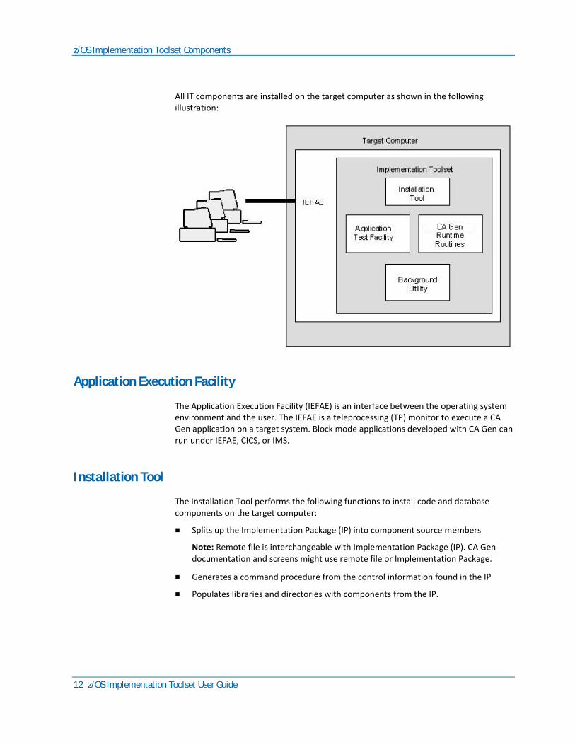
All IT components are installed on the target computer as shown in the following illustration:
Application Execution Facility
The Application Execution Facility (IEFAE) is an interface between the operating system environment and the user. The IEFAE is a teleprocessing (TP) monitor to execute a CA Gen application on a target system. Block mode applications developed with CA Gen can run under IEFAE, CICS, or IMS.
Installation Tool
The Installation Tool performs the following functions to install code and database components on the target computer:
■ Splits up the Implementation Package (IP) into component source members
Note: Remote file is interchangeable with Implementation Package (IP). CA Gen documentation and screens might use remote file or Implementation Package.
■ Generates a command procedure from the control information found in the IP
■ Populates libraries and directories with components from the IP.
z/OS Implementation Toolset Components
Chapter 1: z/OS Implementation Toolset 13
Use the Installation Tool to:
■ Store, configure, and install applications on a target system. These applications are created using the remote files created on the CA Gen code generation platform.
■ Create and install load modules (LM) contained in remote files that were split into components. This is useful during diagram testing and when changes made to one application component forces reinstallation of other components.
■ Set up and maintain one or more target configurations on one or more target systems.
■ Load scripts to use during application installation, view the available scripts, and view the actual values assigned to the script tokens.
Application Test Facility
Use the Application Test Facility to test a CA Gen-generated application by interactively stepping through the action diagrams.
More information:
Testing Applications (see page 77)
Background Utility
The background utility is a TSO function to run JCL, process multiple command procedures, and continue to access the terminal at the same time.
Runtime Routines
Runtime routines are programs that perform low-level functions such as:
■ Accessing the runtime profile database (RPROF table)
■ Parsing unformatted input
■ Formatting screen output
The CA Gen runtime exploits LE storage management, is LE conformant, fully re-entrant, and threadsafe. Most of the CA Gen runtimes are implemented as DLLs so multiple CA Gen applications share a single copy.
Installation Process Overview
14 z/OS Implementation Toolset User Guide
Installation Process Overview
To install a CA Gen-generated application in a z/OS environment, follow these steps:
■ Load the scripts
■ Define the target environment
■ Transfer the implementation package
■ Complete the construction of code
Load the Scripts
A script contains the specific commands to compile and link steps for the IP. Scripts use tokens to represent the variable elements of the MAKE command procedure. The IT interprets the script and replaces the tokens with information about the remote file to produce a complete command procedure.
You must load the scripts before defining the target configuration.
More information:
Loading the Scripts (see page 19)
Define the Target Configuration
Specify all the variable elements of the target system operating environment, including the operating system, programming language, database management system (DBMS), screen format type, and teleprocessing monitor used for implementation.
The target configuration must be defined before construction of the executable code can occur on the target system.
More information:
Defining the Target Configuration (see page 27)

Installation Process Overview
Chapter 1: z/OS Implementation Toolset 15
Transfer Implementation Packages
Transfer the Implementation Packages (IPs) from the workstation to the mainframe host using the file transfer system of your choice.
This function occurs outside the CA Gen environment. If you are unsure how to transfer IPs, contact your system administrator.
Complete the Construction of Code
Complete the construction of the CA Gen-generated code by installing the executable code and application database on the target system using these processes:
■ Process the DDL IP to create the application database.
■ Process the cascade IP to create the Referential Integrity (RI) trigger routines.
■ Process the load module IPs to create executable load modules.
More information:
Process the DDL IP (see page 15) Process the Cascade IP (see page 15) Process the Load Module (see page 16)
Process the DDL IP
The DDL IP is registered in the IT configuration database and the install control module (ICM) is split from the DDL.The DDL is executable as it exists. No compilation or linking is required and script processing is not involved.
More information:
Creating an Application Database (see page 43)
Process the Cascade IP
Referential Integrity (RI) trigger IPs are named CASCADE.RMT on the workstation where they are constructed. They are named TIUPREF.IEF.CASCADE.TIUSUFX on the host system. When the RI trigger IP is transferred to the target system, you can assign it a different name.
Note: Processing is not based on the IP name containing the word CASCADE.
Installation Process Overview
16 z/OS Implementation Toolset User Guide
TIUPREF and TIUSUFX are installation variables specified during CA Gen installation. TIUPREF is usually the user ID, but does not have to be. TIUSUFX is usually null and is not required.
The RI trigger routines are compiled and placed in a library. They are available to be linked into individual load modules as needed when installing the load modules.
More information:
Processing the Cascade IP (see page 45)
Process the Load Module
Processing the load module IPs creates executable load modules.
Follow these steps:
1. Register and validate the IP for the specified target environment.
2. Split the IP into its components and delete the IP when the delete option is selected.
3. Compose the load module MAKE file.
4. Execute the load module MAKE file.
5. Install the load module.
These steps can be automated through the IP Action menu or selectively performed through the Detailed IP Action menu.
More information:
Creating Executable Load Modules (see page 47)
Register and Validate the IP
During IP registration, the Installation Tool validates the contents of the IP. Validation includes:
■ Ensuring that the operating system, DBMS, language, teleprocessing monitor, and screen type selections in the ICM match those in the target configuration.
■ Placing information about the generated source elements into the configuration database

Installation Process Overview
Chapter 1: z/OS Implementation Toolset 17
Split the IP
After validation, the Installation Tool splits the IP into components and stores them in appropriate directory locations for the target configuration definition. If you requested to delete the IP after it is split, the source IP file is deleted from the original location.
Note: In the z/OS environment, you can generate a load module or RI trigger IP with one teleprocessing monitor selection and test that IP using a different teleprocessing monitor. Keep the original IP to install in more than one target configuration without requiring regeneration. If you turn on the trace facility when generating the load module, the additional code that implements trace can cause inconsistent results when installing the load module for IMS or CICS.
Compose the Load Module MAKE File
After the IP is split, a command procedure, often called a MAKE procedure, is created to control the build step for the IP, that is the compile, link, and, if necessary, bind. When invoked, the MAKE procedure compiles source code into load libraries, then links to the appropriate libraries to create the executable programs.
The MAKE file is built using the script associated with the target configuration where the generated application is to reside. The appropriate tokens in the script are replaced with specific information about the components to install and the location of those components after installation.
Execute the Load Module MAKE File
Before executing the MAKE file to install any load module IPs, you must perform the following tasks:
■ Resolve all external action blocks
■ Install the DDL IP for the application
■ Install the RI trigger IP for the application
After the MAKE file executes, the resulting components are stored in the locations specified for that target configuration.

Installation Process Overview
18 z/OS Implementation Toolset User Guide
Install the Load Module
When installing the application in the IEFAE environment, the Application Execution Environment (AEENV) file, called the tranmap file, contains the transaction codes, called trancodes, that allow the IEFAE and the Application Test Facility to identify each load module in the target configuration. These transaction codes allow access to any load module installed in that target configuration.
The Installation Tool automatically updates the tranmap file with the transaction codes for the load modules installed, making the application immediately accessible through the IEFAE.
When installing the executable in the IEFAE environment, additional command files are built that allow access to the application using any clear screen trancode. CA Gen runtime DLLs must also be made available to the IEFAE environment where the application is being tested.
The tranmap (AEENV) file is not created if the load module is to be installed in CICS or IMS.
When installing the application in the CICS environment, you must define all program names and trancodes to CICS by updating the CICS program and table definitions. When installing the application in the IMS environment, you must define all program names and trancodes to IMS using the IMS TRANSACT and APPLCTN macros.
Note: For sample table definitions for CA Gen-generated applications and information about the runtimes required to execute the application in CICS or IMS, see the z/OS Installation Guide.
In the z/OS environment, the load module that results from the final link-edit is stored in the EXE loadlib location. When installing a load module, CA Gen copies it from the EXE loadlib location to the implementation load library location, that is Impl loadlib. Ensure that the EXE and Impl loadlibs are created as PDSE (DSNtype=library) data sets. You can specify the EXE loadlibs and Impl loadlibs during target configuration construction at the target, model, and business system levels. At least one of these loadlibs is required. The search order is business system, model, and last target level.
More information:
Testing, Production, and Maintenance (see page 109)
Chapter 2: Loading the Scripts 19
Chapter 2: Loading the Scripts
Loading scripts is the first step in configuring the target system. After the scripts are loaded, you can view the contents of the scripts and the tokens contained in the scripts.
It is not necessary to view the scripts or tokens before configuring the target. You can view scripts and tokens when you want, or choose not to view them at all.
This chapter provides specific instructions for:
■ Loading scripts
■ Viewing contents of scripts
■ Viewing the tokens in the scripts
Introduction
Loading scripts is the first step in configuring the target system. After loading the scripts, you can view the contents of the scripts and the tokens in the scripts.
It is not necessary to view the scripts or tokens before configuring the target. You can view scripts and tokens when you want, or choose not to view them at all.
This chapter includes specific instructions to load the scripts, view the content of the scripts, and view the tokens in the scripts.
To select options in menus, type the option number in the blank next to the left of the first option and press Enter
Navigating Through the Toolset
20 z/OS Implementation Toolset User Guide
Navigating Through the Toolset
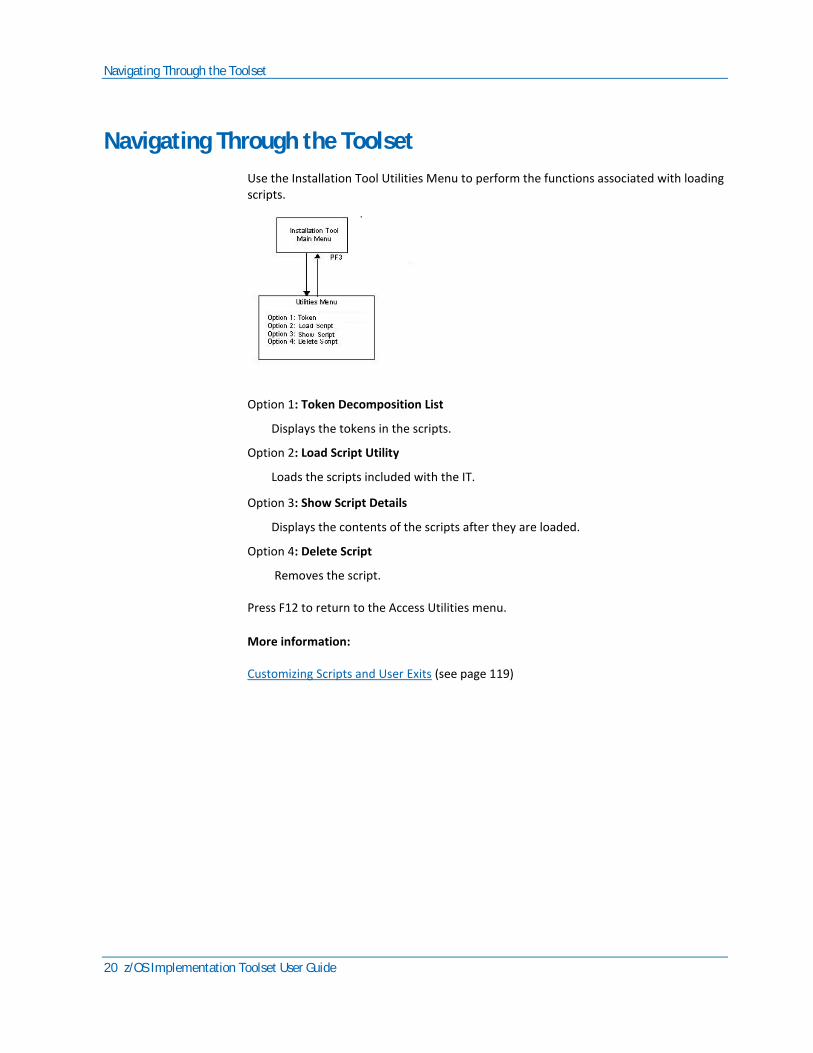
Use the Installation Tool Utilities Menu to perform the functions associated with loading scripts.
Option 1: Token Decomposition List
Displays the tokens in the scripts.
Option 2: Load Script Utility
Loads the scripts included with the IT.
Option 3: Show Script Details
Displays the contents of the scripts after they are loaded.
Option 4: Delete Script
Removes the script.
Press F12 to return to the Access Utilities menu.
More information:
Customizing Scripts and User Exits (see page 119)

What is a Script
Chapter 2: Loading the Scripts 21
What is a Script
Scripts are tokenized command procedures that are interpreted by the IT to create executable compile and link procedures. A script contains all the specific commands necessary to perform the compile, link, and bind for the Implementation Package (IP). The IT installation process copies the scripts from the distribution media to your system.
Each target configuration is associated with a script that specifies one of each of the following:
■ the DBMS, DB2
■ the application language, COBOL
■ a teleprocessing monitor, IEFAE, CICS, or IMS
■ the screen format type, MAPPED or BYPASS
The IT contains a set of valid basic scripts for your specific operating environment that can be installed as is or customized by a system administrator.
During the installation of an IP, the IT interprets the script and replaces the tokens with information about the IP and produces a MAKE file with information from the configuration database. The IT submits the MAKE file for execution.
Supplied Scripts
There are two scripts supplied with the IT and located in the CEHBSAMP library:
■ a load module script called TIXMVSLM
■ an RI trigger script called TIXMVSRI
A pair of script files, one for the load module and one for the RI trigger, must be loaded for every combination of script parameters supported at your site. For example, if CICS/DB2, and IEFAE/DB2 are the target configuration for your site, you must load a pair of CICS scripts, that is LM and RI scripts, for DB2, and a pair of IEFAE scripts for DB2.
The scripts supplied with the IT support all valid combinations of target configuration.
Before You Begin Loading Scripts
Before you load the scripts, verify that the following requirements are met:
■ The IT components are installed on your target system
■ The locations for the components specified in this chapter are determined
Loading Scripts
22 z/OS Implementation Toolset User Guide
■ You are logged on to your system with proper security privileges
■ The IT is running with the Installation Tool window displayed
Loading Scripts
Follow these steps:
1. In the Installation Tool window, type 4 to select Option 4:Access Utilities Menu and press Enter.
CA Gen displays the Utilities Menu.
2. Type 2 to select Option 2: Load Script Utility and press Enter.
The Load Script screen displays.
3. With the Load Script screen displayed, tab to the Load Module Script Name field. Type the logical name of the load module script. The name can be up to 32 characters long. For example, CICS script.
4. Tab to the Load Module Script Data Set field. Type the name of the IT's CEHBSAMP enclosed in quotes.
5. Tab to the Load Module Script Member field. Type TIXMVSLM.
6. Tab to the RI Trigger Script Name field. Type the logical name of the RI trigger script. The name can be up to 32 characters. For example, RI Trigger script for CICS.
7. Tab to the RI Trigger Script Data Set field. Type the name of the IT's CEHBSAMP enclosed in quotes.
8. Tab to the RI Trigger Script Member field. Type TIXMVSRI.
9. Tab to the Description field. Type a text description of the script files. For example, Distributed script files for CICS. This optional field is for informational purposes only.
10. Tab to the Language field. Use the default value COBOL.
11. Tab to the DBMS field. Your choice is: DB2.
12. Tab to the TP Monitor field. Type the teleprocessing monitor to be used with this script configuration. Your choices are: IEFAE, IMS, or CICS.
13. Tab to the Screen Format field. This is the block mode format of the CA Gen application to be installed by this script. Your choices are:
■ BYPASS—For use with IEFAE, IMS, and CICS applications
■ MAPPED—For use with IMS only
14. Tab to the Hardware Platform field. This optional field is for informational purposes only.
15. Tab to the OS field. The default value of MVS is correct.
Viewing Scripts
Chapter 2: Loading the Scripts 23
16. Tab to the USER ID field. This is the TSO ID of the current user. This optional field is for informational purposes only.
17. Accept the default values for the Directive, Token, and Comment Delimiters fields.
18. Confirm the data you entered is correct. Press the Enter key to initiate the load. When the load is complete, the system displays the following message:
Processing has completed normally
You have two options at this point:
■ Load additional scripts. Repeat Steps 3 through 18.
■ Define the target configuration. Press F3 to display the Installation Tool window. For more information about defining the target configuration, see the chapter Defining the Target Configuration.
Viewing Scripts
Before you can view scripts from the Show Script Screen, you must first load the scripts from the Load Script Screen. The Show Script Screen is a view-only screen.
To view scripts
With the Installation Tool window displayed, select Option 4 (Access Utilities Menu) by typing a 4 in the blank to the left of Option 1 and press Enter to display the Utilities Menu.
Select Option 3 (Show Script Details) by typing a 3 in the blank to the left of Option 1 and press Enter. The Show Script screen is displayed.
Select the script to view using one of these methods:
■ Tab to the Script Name field and type the name of the script to view (for example, CICS script). Press Enter to display the script.
■ Press F5 to scroll alphabetically through a list of scripts that have already been loaded.
With the correct script displayed, press F4 to display the Show Script Lines screen. This screen displays the script on a line-by-line basis. Use the F7 and F8 keys to scroll forward and backward through the script lines.
Press F3 to display the Installation Tool window.
Press F15 to display the IT window.
Viewing Tokens
24 z/OS Implementation Toolset User Guide
Viewing Tokens
You can view tokens at five different levels. To view tokens at the target level, enter the name of the selected target (or locate the name in the alphabetical listing of targets). Leave the rest of the fields blank.
Each level of tokens below the target level is dependent on the level above it for its identity. (For example, there can be a model named ORDERS in both TARGET A and TARGET B) To make sure that you are viewing the correct version of the ORDERS model, the target name must be specified with the model name. This type of relationship occurs at the business system level, the load module definition level, and the load module member level. For more information, see Tokens in the chapter Customizing Scripts in this guide.
Follow these steps:
1. With the Installation Tool window displayed, select Option 4 Access Utilities Menu by typing 4 in the blank to the left of Option 1 and pressing Enter.
2. With the Utilities Menu displayed, select Option 1 Token Decomposition List by typing 1 in the blank to the left of Option 1 and pressing Enter. The Decomposition Report screen is displayed.
3. From the Decomposition Report screen, display the Token that you want:
■ Type the name of the components whose tokens you want to view and press Enter.
■ Scroll alphabetically through the token database until the correct token is displayed.
4. Tab to the Target Name field. Press F4. The Selection List screen is displayed. Type a / next to the target you want and press Enter. The Decomposition Report screen is displayed.
5. Tab to the Model Name field. Press F4. The Selection List screen is displayed. Type a / next to the model you want and press Enter. The Decomposition Report screen is displayed.
6. Tab to the Bussys Name field. Press F4. The Selection List screen is displayed. Type a / next to the business system you want and press Enter. The Decomposition Report screen is displayed.
7. Tab to the LM Def Name field. Press F4. The LM Def Definition List screen is displayed. Type a / next to the LM Definition you want and press Enter. The Decomposition Report screen is displayed.
8. Tab to the LM Mem Name field. Press F4. The LM Mem Definition List screen is displayed. Type a / next to the LM Mem Name you want and press Enter. The Decomposition Report screen is displayed.

Viewing Tokens
Chapter 2: Loading the Scripts 25
When you have selected a set of elements that have tokens associated with them, the columns in the bottom portion of the screen provide information about the first five tokens in the list. If there are more than five tokens for this element, scroll forward through the list by pressing F7 and scroll backward through the list by pressing F8. The following table describes the columns at the bottom of the screen that contain information on the tokens associated with the selected elements.
Column Name Description
Type This is the token type. Values are:
- LIB
- LOC
- LMD
- LMM
- TAR
- MOD
- BUS
- OPT
Token Name/ Value Field
This is the name of the token, and the value field indicating the replacement string for that token. This replacement string is the value that is substituted into the MAKE procedure in place of the token name when an IP is installed.
Seq # This is the sequence number for the token when there is more than one token occurrence for a given type.
9. Press F3 to display the Installation Tool window.
10. Press F15 to display the IT window.


Chapter 3: Defining the Target Configuration 27
Chapter 3: Defining the Target Configuration
The Implementation Toolset
The IT can install applications and build databases on different target platforms. This chapter shows you how to define the target platform. This process is called target configuration.
The functions associated with defining a target configuration are performed through Option 3 Maintain Configuration Information on the IT window.
Before You Begin
Before you configure a target, you must:
■ Make sure the IT components are installed on your target system.
■ Determine the locations for the components specified in this chapter.

Target Definition
28 z/OS Implementation Toolset User Guide
■ Be logged on to your system with the proper security privileges.
■ Make sure the IT is running and the Installation Tool window is displayed.
■ Make sure the scripts have been loaded.
■ Member TIXIVPLB in the IT JCL library can be used to allocate the libraries. Note that the NCALLOAD, EXELOAD, IMPLOAD, RINCAL, NCALC, RINCALC, and RIEXEC libraries are allocated as PDSE (DSNtype=library). Review the JCL, make the necessary changes, and submit the job.
Target Definition
This section shows you how to perform the following functions:
■ Add a target
■ Duplicate a target
■ Modify a target
■ Delete a target
Add a Target
Follow these steps:
1. With the IT window displayed, select Option 1. The Installation Tool window is displayed.
2. Select Option 3, Maintain Configuration Information. The Select Script List screen is displayed.
Note: The Select Script screen is automatically displayed when a target configuration does not exist. After a target is configured, the Select Script screen is replaced with the Selection List screen.
3. Select the script that you want to associate with the target configuration and press Enter. The Target Definition screen is displayed.
4. Tab to the Target field. Type a logical name for the target configuration you are defining.
5. Tab to the Desc field. This information field is used to further define the logical name specific in the Target field (Step 4).
6. For DB2 scripts, tab to the DB2Sys field and type the DB2 subsystem ID. This is used during DDL installation and DB2 bind steps.

Target Definition
Chapter 3: Defining the Target Configuration 29
7. For DB2 scripts, tab to the Target Test Facility field. Select YES or NO. Selecting YES causes all applications installed into this environment to be installed under the Application Test Facility.
8. Press Enter to add the Target. The system responds with the message:
Processing has completed normally
9. Press F5 to display the Specify Locations screen. This screen is used to specify target level data sets for the different components of the target environment. For a description of locations, usage, and data set attributes, use the following table.
Contents of File Usage Data Set Attributes
source Lib Contains generated source split from Implementation Packages (IPs).
PO, RECFM=FB, LRECL=80, BLKSIZE=27920
Ncal Load Lib* Contains unresolved load modules output from compile process.
PO, RECFM=U, LRECL=0, BLKSIZE=19069, DSNTYPE=LIBRARY
Exe Load Lib* Contains fully resolved executable load modules.
PO, RECFM=U, LRECL=0, BLKSIZE=19069, DSNTYPE=LIBRARY
Impl Load Lib* Contains implemented load modules; the install step copies modules from the exe loadlib to the Impl loadlib.
PO, RECFM=U, LRECL=0, BLKSIZE=19069, DSNTYPE=LIBRARY
DBRM Lib Contains DBRMs created by the DB2 pre-compiler.
PO, RECFM=FB, LRECL=80, BLKSIZE=27920
Inst Ctl Lib Contains load module ICMs split from IPs.
PO, RECFM=FB, LRECL=80, BLKSIZE=27920
Listing Lib Contains compiler listings (optional).
PO, RECFM=FBA, LRECL=133, BLKSIZE=13300
Clist Lib Contains generated MAKE procedures.
PO, RECFM=FB, LRECL=80, BLKSIZE=27920
Tranmap File The IEFAE file that associates trancodes to load modules.
PS, RECFM=FB, LRECL=80, BLKSIZE=27920
Appl Clist Lib Contains generated commands to invoke an application under IEFAE (one command for each clear screen trancode).
PO, RECFM=FB, LRECL=80, BLKSIZE=27920
MFS Source Lib Contains generated MFS code split from IPs.
PO, RECFM=FB, LRECL=80, BLKSIZE=27920
Target Definition
30 z/OS Implementation Toolset User Guide
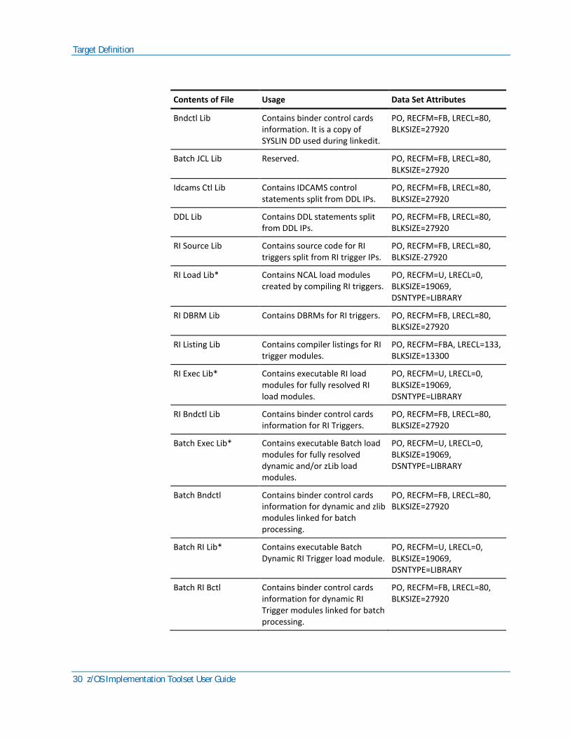
Contents of File Usage Data Set Attributes
Bndctl Lib Contains binder control cards information. It is a copy of SYSLIN DD used during linkedit.
PO, RECFM=FB, LRECL=80, BLKSIZE=27920
Batch JCL Lib Reserved. PO, RECFM=FB, LRECL=80, BLKSIZE=27920
Idcams Ctl Lib Contains IDCAMS control statements split from DDL IPs.
PO, RECFM=FB, LRECL=80, BLKSIZE=27920
DDL Lib Contains DDL statements split from DDL IPs.
PO, RECFM=FB, LRECL=80, BLKSIZE=27920
RI Source Lib Contains source code for RI triggers split from RI trigger IPs.
PO, RECFM=FB, LRECL=80, BLKSIZE-27920
RI Load Lib* Contains NCAL load modules created by compiling RI triggers.
PO, RECFM=U, LRECL=0, BLKSIZE=19069, DSNTYPE=LIBRARY
RI DBRM Lib Contains DBRMs for RI triggers. PO, RECFM=FB, LRECL=80, BLKSIZE=27920
RI Listing Lib Contains compiler listings for RI trigger modules.
PO, RECFM=FBA, LRECL=133, BLKSIZE=13300
RI Exec Lib* Contains executable RI load modules for fully resolved RI load modules.
PO, RECFM=U, LRECL=0, BLKSIZE=19069, DSNTYPE=LIBRARY
RI Bndctl Lib Contains binder control cards information for RI Triggers.
PO, RECFM=FB, LRECL=80, BLKSIZE=27920
Batch Exec Lib* Contains executable Batch load modules for fully resolved dynamic and/or zLib load modules.
PO, RECFM=U, LRECL=0, BLKSIZE=19069, DSNTYPE=LIBRARY
Batch Bndctl Contains binder control cards information for dynamic and zlib modules linked for batch processing.
PO, RECFM=FB, LRECL=80, BLKSIZE=27920
Batch RI Lib* Contains executable Batch Dynamic RI Trigger load module.
PO, RECFM=U, LRECL=0, BLKSIZE=19069, DSNTYPE=LIBRARY
Batch RI Bctl Contains binder control cards information for dynamic RI Trigger modules linked for batch processing.
PO, RECFM=FB, LRECL=80, BLKSIZE=27920
Target Definition
Chapter 3: Defining the Target Configuration 31
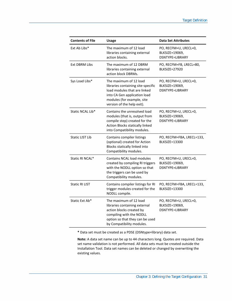
Contents of File Usage Data Set Attributes
Ext Ab Libs* The maximum of 12 load libraries containing external action blocks.
PO, RECFM=U, LRECL=0, BLKSIZE=19069, DSNTYPE=LIBRARY
Ext DBRM Libs The maximum of 12 DBRM libraries containing external action block DBRMs.
PO, RECFM=FB, LRECL=80, BLKSIZE=27920
Sys Load Libs* The maximum of 12 load libraries containing site-specific load modules that are linked into CA Gen application load modules (for example, site version of the help exit).
PO, RECFM=U, LRECL=0, BLKSIZE=19069, DSNTYPE=LIBRARY
Static NCAL Lib* Contains the unresolved load modules (that is, output from compile step) created for the Action Blocks statically linked into Compatibility modules.
PO, RECFM=U, LRECL=0, BLKSIZE=19069, DSNTYPE=LIBRARY
Static LIST Lib Contains compiler listings (optional) created for Action Blocks statically linked into Compatibility modules.
PO, RECFM=FBA, LRECL=133, BLKSIZE=13300
Static RI NCAL* Contains NCAL load modules created by compiling RI triggers with the NODLL option so that the triggers can be used by Compatibility modules.
PO, RECFM=U, LRECL=0, BLKSIZE=19069, DSNTYPE=LIBRARY
Static RI LIST Contains compiler listings for RI trigger modules created for the NODLL compile.
PO, RECFM=FBA, LRECL=133, BLKSIZE=13300
Static Ext Ab* The maximum of 12 load libraries containing external action blocks created by compiling with the NODLL option so that they can be used by Compatibility modules.
PO, RECFM=U, LRECL=0, BLKSIZE=19069, DSNTYPE=LIBRARY
* Data set must be created as a PDSE (DSNtype=library) data set.
Note: A data set name can be up to 44 characters long. Quotes are required. Data set name validation is not performed. All data sets must be created outside the Installation Tool. Data set names can be deleted or changed by overwriting the existing values.

Target Definition
32 z/OS Implementation Toolset User Guide
10. Press Enter to process the changes. The system responds with the following message:
Location updates were successful.
11. Press F3 to display the Installation Tool window.
Duplicate a Target
This section gives you specific instructions for duplicating a target configuration.
Note: If a target that has related models and business systems is copied, only the target is copied. The models and business systems are not duplicated.
Follow these steps:
1. With the IT window displayed, select Option 1.
The Installation Tool window is displayed.
2. Select Option 3, Maintain Configuration Information.
The Selection List screen is displayed.
3. Select the target configuration you want and press F10.
The Copy Target screen is displayed. There are two fields on the Copy Target screen. The Old Target Name field contains the name of the target you selected in Option 3.
4. Tab to the New Target Name field and type the name of the new target configuration and press Enter.
The system duplicates the target configuration. The following message is displayed when processing is complete:
Processing has completed normally
5. Press F12 to return to the Selection List screen.
The new target is in the list of targets displayed on this screen.
6. Press F3 to display the Installation Tool window.
Modify a Target
This section explains how to modify a target definition from the configuration database. You can modify the following fields on the Target Definition screen:
■ Script
■ Description
■ DB2 system ID
■ Target Test Facility

Target Definition
Chapter 3: Defining the Target Configuration 33
■ Locations
■ Options
Follow these steps:
1. With the IT window displayed, select Option 1.
The Installation Tool window is displayed.
2. Select Option 3, Maintain Configuration Information.
The Selection List screen is displayed.
3. Select the target configuration you want and press Enter.
The Target Definition screen is displayed.
4. Press F4 to change the associated script. The Script List screen is displayed. Select the script you want and press Enter.
The Target Definition screen is displayed.
5. Tab to the Desc field. To update this field, type the new value over the old value. Make sure you remove any characters from the old value by spacing over the old characters.
6. For DB2 scripts, tab to the DB2Sys field. Make sure you remove any characters from the old value by spacing over the old characters.
7. For DB2 scripts, tab to the Target Test Facility field. Select YES or NO. Selecting YES causes all applications installed in this environment to be installed under the Application Test Facility.
8. Press Enter to update the Target definition.
The system responds with the message:
Processing has completed normally
9. Press F13 to change the options. The Options screen is displayed. Type the option information into the columns and press Enter. The system responds with the following message:
Processing has completed normally.
10. Press F12 to display the Target Definition screen.
11. Press F5 to display the Specify Locations screen. This screen is used to specify target-level data sets for the different components of the target environment. For a description of locations, usage, and data set attributes, see the locations table in the To Add a Target section in this chapter.
12. Press Enter to process the changes.
The system responds with the following message:
Location updates were successful.
13. Press F3 to display the Installation Tool window.
Model Definition
34 z/OS Implementation Toolset User Guide
Delete a Target
The principle of Referential Integrity (RI) applies to the function of deleting a CA Gen target definition. When a target is deleted, all related models and business systems are also deleted. However, the script associated with the target is not deleted.
Note: If you delete the wrong target, you must reenter each element of a deleted target separately.
The delete process removes the records from the IT configuration database, but it does not delete any data sets. Your definition still exists, but it is not identified to the IT. To reclaim this disk space, you must delete the files from the disk.
Follow these steps:
1. With the IT window displayed, select Option 1.
The Installation Tool window is displayed.
2. Select Option 3, Maintain Configuration Information.
The Selection List screen is displayed.
3. Select the target configuration you want to delete and press Enter.
The Target Definition screen is displayed.
4. Press F10 to delete the target definition.
The system responds with the following message:
Press ENTER to confirm delete request or F12 to cancel delete request
5. Verify that the target definition displayed is the one to delete and press Enter.
The system responds by displaying the Selection List screen.
6. Press F3 to display the Installation Tool window.
Model Definition
This section explains how to perform the following procedures:
■ Add a model
■ Modify a model
■ Delete a model
Note: These procedures are optional.
Model Definition
Chapter 3: Defining the Target Configuration 35
Add a Model
Follow these steps:
With the IT window displayed, select Option 1. The Installation Tool window is displayed.
1. Select Option 3, Maintain Configuration Information.
The Selection List screen is displayed.
2. Select the target configuration you want to define models for and press Enter.
The Target Definition screen is displayed.
3. Press F2 to add a model.
The Model Definition screen is displayed.
4. Tab to the Model field. Type a valid model name. This is the name of the model on the code generation platform. It appears in the ICM.
5. For DB2 scripts, tab to the DB2Sys field and type the DB2 subsystem ID. This is used during DDL installation, and DB2 bind steps.
6. Press Enter to add the Model.
The system responds with the message:
Processing has completed normally
7. Press F5 to display the Specify Locations screen. This screen is used to specify model level data sets for the different components of the model in the target environment. For a description of locations, usage, and data set attributes, see the locations table in the To Add a Target section in this chapter.
Note: A data set name can be up to 44 characters long. Quotes are required. Data set name validation is not performed. All data sets must be created outside the Installation Tool. Data set names can be deleted or changed by overwriting the existing values. Ensure that all Load libs and Ext Ab libs are created as a PDSE (DSNtype=library) data set.
8. Press Enter to process the changes.
The system responds with the following message:
Location updates were successful.
9. Press F3 to display the Installation Tool window.
Modify a Model
This section explains how to modify a model definition from the configuration database. You can modify the following fields on the Model Definition screen:
■ DB2 system ID

Model Definition
36 z/OS Implementation Toolset User Guide
■ Locations
■ Options
Follow these steps:
1. With the IT window displayed, select Option 1.
The Installation Tool window is displayed.
2. Select Option 3, Maintain Configuration Information.
The Selection List screen is displayed.
3. Select the target configuration and press Enter.
The Target Definition screen is displayed.
4. Press F2 to display the Selection List screen. Select the correct model and press Enter.
The Model Definition screen is displayed.
5. For DB2 scripts, tab to the DB2Sys field and type the DB2 subsystem ID. This is used during DDL installation, and DB2 bind steps.
6. Press Enter to change the Model.
The system responds with the message:
Processing has completed normally
7. Press F5 to display the Specify Locations screen. This screen is used to specify model-level data sets for the different components of the model in the target configuration. For a description of locations, usage, and data set attributes, see the locations table in the To Add a Target section in this chapter.
8. Press Enter to process the changes.
The system responds with the following message:
Location updates were successful.
9. Press F13 to change the options.
The Options screen is displayed. Type the option information into the columns and press Enter. The Target Definition screen is displayed.
10. Press F3 to display the Installation Toolset window.
Business System Definition
Chapter 3: Defining the Target Configuration 37
Delete a Model
The principle of Referential Integrity (RI) applies to the function of deleting a model. When a model is deleted, all related business systems are also deleted. However, the script associated with the model is not deleted.
Note: If you delete the wrong model definition, you must reenter each element of a deleted model definition separately.
The delete process removes the records from the IT configuration database, but does not remove any data sets. Your definition still exists, but it is not identified to the IT. To reclaim this disk space, you must delete the files from the disk.
Follow these steps:
1. With the IT window displayed, select Option 1.
The Installation Tool window is displayed.
2. Select Option 3, Maintain Configuration Information.
The Selection List screen is displayed.
3. Select the correct target configuration and press Enter.
The Target Definition screen is displayed.
4. Press F2 to display the Selection List screen.
5. Select the model configuration you want to delete and press Enter.
The Model Definition screen is displayed.
6. Press F10 to delete the model definition.
The system responds with the following message:
Press ENTER to confirm delete request or F12 to cancel delete request
7. Verify that the model definition displayed is the one to delete and press Enter.
The system responds by displaying the Selection List screen.
8. Press F3 to display the Installation Tool window.
Business System Definition
This section explains how to perform the following procedures:
■ Add a business system
■ Modify a business system
■ Delete a business system

Business System Definition
38 z/OS Implementation Toolset User Guide
Note: These procedures are optional.
Add a Business System
Follow these steps:
1. With the IT window displayed, select Option 1.
The Installation Tool window is displayed.
2. Select Option 3, Maintain Configuration Information.
The Selection List screen is displayed.
3. Select the target configuration and press Enter.
The Target Definition screen is displayed.
4. Press F2 to select a model.
The Selection List screen is displayed.
5. Select the model you want and press Enter.
The Model Definition screen is displayed.
6. Press F2 to add a Business System.
The BUSSYS Definition screen is displayed.
7. Tab to the BSYS field. Type a valid business system name. This is the name of the business system on the code generation platform. It appears as the techsys in the ICM.
8. Press Enter to add the business system.
The system responds with the message:
Processing has completed normally
9. Press F5 to display the Specify Locations screen. This screen is used to specify business system data sets for the different components of the business system in the target environment. For a description of locations, usage, and data set attributes, see the locations table in the To Add a Target section in this chapter.
10. Press Enter to process the changes.
The system responds with the following message:
Location updates were successful.
11. Press F12 to return to the BUSSYS Definition screen. Press F13 to display the Options screen. Type the option information into the columns and press Enter.
The system responds with the following message:
Process has completed normally.

Business System Definition
Chapter 3: Defining the Target Configuration 39
12. Press F12 to return to the BUSSYS Definition screen.
The BUSSYS Definition screen is displayed.
13. Press F3 to display the Installation Tool window.
Modify a Business System
This section explains how to modify a business system definition from the configuration database. (This step is optional.) You can modify the following fields on the Business System Definition screen:
■ Locations
■ Options
Follow these steps:
1. With the IT window displayed, select Option 1.
The Installation Tool window is displayed.
2. Select Option 3, Maintain Configuration Information.
The Selection List screen is displayed.
3. Select the target configuration and press Enter.
The Target Definition screen is displayed.
4. Press F2 to display the Selection List screen. Select the correct model and press Enter.
The Model Definition screen is displayed.
5. Press F2 to display the BUSSYS Selection screen.
6. Select the correct business system and press Enter.
The BUSSYS Definition screen is displayed.
7. Press F5 to display the Specify Locations screen. This screen is used to specify business system-level data sets for the different components of the business system in the target configuration. For a description of locations, usage, and data set attributes, see the locations table in the To Add a Target section in this chapter.
8. Press Enter to process the changes.
The system responds with the following message:
Location updates were successful.
9. Press F12 to return to BUSSYS Definition screen.
Business System Definition
40 z/OS Implementation Toolset User Guide
10. Press F13 to display the Options screen. Type the option information into the columns and press Enter.
The Model Definition screen is displayed.
11. Press F3 to display the Installation Tool window.
Delete a Business System
The principle of Referential Integrity (RI) applies to the function of deleting a business system definition. The script associated with the business system definition is not deleted.
Note: If you delete the wrong business system definition, you must reenter each element of a deleted business system definition separately.
The delete process removes the records from the IT configuration database, but does not remove any data sets. Your definition still exists, but it is not identified to the IT. To reallocate this disk space, you must delete the files from the disk.
Follow these steps:
1. With the IT window displayed, select Option 1.
The Installation Tool window is displayed.
2. Select Option 3, Maintain Configuration Information.
The Selection List screen is displayed.
3. Select the target configuration and press Enter.
The Target Definition screen is displayed.
4. Press F2 to display the Selection List screen.
5. Select the model configuration and press Enter.
The Model Definition screen is displayed.
6. Press F2 to display the BUSSYS Selection screen.
7. Select the business system that you want to delete and press Enter.
The BUSSYS Definition screen is displayed.
8. Press F10 to delete the business system definition.
The system responds with the following message:
Press Enter and confirm delete request or F12 to cancel delete request
Business System Definition
Chapter 3: Defining the Target Configuration 41
9. Verify that the business system definition displayed is the one to delete and press Enter.
The system responds by displaying the Selection List screen.
10. Press F3 to display the Installation Tool window.


Chapter 4: Creating an Application Database 43
Chapter 4: Creating an Application Database
This chapter describes how the IT processes the DDL Implementation Package (IP) to create the application database. The following functions are performed:
■ Register the IP in the configuration database.
■ Split the IP into the appropriate location.
■ Create a command file.
■ Invoke DDL to create the tables and indexes.
The functions associated with processing the DDL IP are performed through the Installation Tool menu.
Before You Begin
Before you can process the DDL IP, you must:
■ Make sure the IT components are installed on your target system.
■ Determine the locations for the components specified in this chapter.
■ Be logged on to your system with the proper security privileges.
■ Make sure the IT is running and the IT window is displayed.
■ Make sure the scripts have been loaded.
■ Make sure the target libraries are allocated. Member TIXIVPLB in the IT JCL library can be used to allocate the libraries. Note that the NCALLOAD, EXELOAD, IMPLOAD, RINCAL, NCALC, RINCALC, and and RIEXEC libraries are allocated as PDSE (DSNtype=library). Review the JCL, make the necessary changes, and submit the job.
■ Make sure the target is configured.
Process the DDL IP
This section explains how to process the DDL IP.
Note: You must process the DDL IP before processing Load Module IPs.

Process the DDL IP
44 z/OS Implementation Toolset User Guide
Follow these steps:
1. With the IT window displayed, select Option 1.
The Installation Tool window is displayed.
2. Select Option 1, Process Implementation Package.
The Select Implementation screen is displayed.
3. Tab to the Data Set field. Type the data set name of the DDL IP that you want to process.
4. Tab to the Member field. Type the member name if the data set value in Step 3 is a PDS.
5. Tab to the Name field. Type the name of a preconfigured target environment.
6. Press Enter.
The Process DDL Implementation Package screen is displayed.
7. Confirm the data on the screen.
8. Press Enter.
The JCL Job Statement Information Input screen is displayed.
9. Edit this screen to provide job card information.
10. Press Enter. The JCL Edit screen is displayed.
11. Make the necessary changes (volume name, database name) and submit the job. Review the output from the job when it is complete. You have two options at this point:
■ Install the Cascade IP. For more information about installing Cascade IP, see the chapter Processing the Cascade IP.
■ Exit the IT. Press F3 to display the IT window.
Chapter 5: Processing the Cascade IP 45
Chapter 5: Processing the Cascade IP
This chapter describes how to process the Cascade Implementation Package (IP) to create the Referential Integrity (RI) trigger routines and the RI Trigger DLL for dynamic RI Triggers. During processing, the Installation Tool:
■ Registers the IP in the configuration database
■ Splits the IP source members into the appropriate source locations
■ Compiles the source members
■ Builds the RI Trigger DLL for dynamic RI Triggers
The functions associated with processing the cascade IP are performed through the Installation Tool menu.
If the Process modules marked for Compatibility option was selected, the remote file includes the keyword pcompat=YES, which will cause the source members to be compiled twice—once using the NODLL compiler option and again using the DLL compiler option.
If the Dynamically Link RI Triggers option was selected, the remote file includes the keyword dynamri=YES, which will cause all of the RI Trigger modules to be included in a DLL by the same name as the CASCADE name. The RI Trigger DLL will be placed in the loadlib associated with the RI EXEC lib.
If Batch RI Library is specified, the installation process will also create a batch version of dynamic RI DLL executable and will save it in this library automatically. DB2 attachment type for batch dynamic RI will be as specified by the TIRDBATT parameter, defaulting to DSN.
Processing the Cascade IP
Follow these steps:
1. With the IT window displayed, select Option 1.
The Installation Tool window is displayed.
2. Select Option 1, Process Implementation Package.
The Select Implementation Package screen is displayed.
3. Press the F6 key to display the Selection screen for Targets.
Processing the Cascade IP
46 z/OS Implementation Toolset User Guide
4. Tab to the Data Set field. Type the data set name of the cascade IP that you want to process.
5. Tab to the Member field. Enter the member name if the data set value in Step 4 is a PDS.
6. Press Enter.
The IP Action menu is displayed.
7. Select Option 1, Create or update procedure and install IP, by placing a / to the left of the selection.
8. Press Enter.
This starts the process of installing the Cascade IP.
When the processing is complete, you can:
■ Install load module IPs. For more information about installing the load module IPs, see the chapter Creating Executable Load Modules.
■ Exit. Press F3 to display the IT window.
Chapter 6: Creating Executable Load Modules 47
Chapter 6: Creating Executable Load Modules
This chapter shows how to process the load module (LM) Implementation Package (IP) to create the Executable Load Modules and Opslibs for z/OS (zLIBs). During processing, the Installation Tool:
■ Registers and validates the IP for the specified target configuration
■ Splits the IP into its components and deletes the IP if the option is selected
■ Composes the MAKE file
■ Executes the MAKE file
■ Installs the load module or zLIB module
The functions associated with processing the load module IP are performed through the Installation Tool menu.
Source code for Load Module components that have their Dynamically Link packaging property set or defaulted to Compatibility is not included in the IP unless the option Process modules marked for Compatibility was also selected.
Selecting the option Process modules marked for Compatibility causes two tokens to be included in the ICM. The two tokens are as follows:
■ PCOMPAT token
The PCOMPAT token, found in the execunit section of the load module, applies to every component of the load module and causes the components to be compiled twice.
■ LINK token
The LINK token is specified for every component that is marked for Compatibility and causes the Implementation Toolset to build the component as a non-DLL load module.
If the load module is defined as a zLIB module (using the toolset), the remote file includes the keyword lmtype=zlib which will cause the modules to be included in a DLL by the same name as the Load Module name. The zLIB (DLL) will be placed in the loadlib associated with the EXEC lib.
The installation process link-edits the dynamic action blocks including z/OS Library modules for batch processing in addition to regular link-edit if Batch Executable library is specified
Process the Load Module IP
48 z/OS Implementation Toolset User Guide
For z/OS Libraries, the online version of z/OS Library DLL will be populated in the regular Executable Load Modules Library. The batch version of z/OS Library will be saved in the Batch Executable library if specified. DB2 attachment type for batch z/OS Library DLLs will be as specified by the TIRDBATT parameter, defaulting to DSN.
Process the Load Module IP
This section explains how to install a single load module IP, including a zLIB module for the first time. For instructions about reinstalling a load module, see Reinstalling a Load Module in this chapter.
Note: The DDL and Cascade IP must be installed before the Load Module IP. Also, any External Action Blocks referenced must be installed.
Follow these steps:
1. With the IT window displayed, select Option 1.
The Installation Tool window is displayed.
2. Select Option 1, Process Implementation Package.
The Select Implementation Package screen is displayed.
3. Press the F6 key to display the Selection Screen for Targets.
4. Place a / next to the target you want and press Enter.
The Select Implementation screen is displayed.
5. Tab to the Data Set field. Type the data set name of the LM IP to process.
6. Tab to the Member field. Type the member name if the data set value in Step 5 is a PDS.
7. Press Enter.
The IP Action menu is displayed.
8. Select Option 1, Create or update procedure and install IP, by placing a / to the left of the selection.
9. Press Enter.
This starts the process to create and install the executable load module IP.
When the processing is complete, do one of the following:
■ Install additional load module IPs.
■ Exit. Press F3 to display the IT window.
Reinstalling a Load Module
Chapter 6: Creating Executable Load Modules 49
Reinstalling a Load Module
When changing a model, it is possible to install only the load modules where the changes occurred. This is useful when you make a change as a result of testing or when External Action Blocks or other related elements have been recompiled and need to be relinked.
Follow these steps:
1. With the IT window displayed, select Option 1.
The Installation Tool window is displayed.
2. Select Option 1, Process Implementation Package.
The Select Implementation Package screen is displayed.
3. Tab to the Data Set field and enter the correct value.
4. Tab to the Member field and enter the correct value.
5. Tab to the Name field. You can either type the correct value for the Target Environment, or press F6 for a list of target environments. Select the correct target and press Enter.
The Select Implementation Package screen is displayed.
6. Press Enter. The IP Action menu is displayed.
7. Select one of the following processing options and press Enter:
■ If the IP has never been processed before, select Option 1 and press Enter. This starts the process to create and install the Executable Load Module IP.
■ If the IP has been processed before and you must change an existing load module's components, select Option 2—Split, Execute, and Install. You can code the changes, regenerate the remote files, split out the new or changed versions of the load module's components, execute, and install.
■ If the IP has been processed before and you want to select a specific processing step, press F6. The Detailed IP Action menu is displayed.
8. When the processing is complete, do one of the following steps:
■ Install another IP.
■ Exit. Press F3 to display the IT window.


Chapter 7: Implementing External Action Blocks 51
Chapter 7: Implementing External Action Blocks
This chapter describes how External Action Blocks access processing logic contained in subroutines that are not generated by CA Gen. You can create an external subroutine to fit a specific need, or you can use code that existed before development of your application system. You create and compile the subroutine independently of CA Gen.
For example, you may want your application system to use a standard date manipulation or security routine defined specifically for your organization. Alternatively, the application may need to access databases that are either not supported by CA Gen toolsets (such as DL/I), or that contain entities (tables) not defined in the model's Data Model.
External Action Blocks are part of a procedure step and have the following characteristics:
■ Called from a procedure step or from an action block
■ Allow view matching
■ Return to the calling procedure step or action block when completed
This chapter discusses:
■ Prerequisites for using External Action Blocks
■ Terms that help you understand the process
■ Overview of the procedure to create and implement an External Action Block
■ Load module structure
■ Creating CA Gen External Action Blocks and the calling procedure steps or action blocks
■ Creating your own External Action Block source
Prerequisites
You must complete the following tasks before you can generate External Action Block code.
■ Create the Data Model and action diagrams for the calling procedure step or action block and the CA Gen External Action Block.
■ Complete the view matching between the calling and called action blocks. This is the information that is passed to the External Action Block.

Terms
52 z/OS Implementation Toolset User Guide
Terms
The following definitions help you to understand the process of creating an External Action Block:
■ External Action Block—CA Gen External Action Blocks are created using the workstation Design Toolset. An External Action Block contains only an EXTERNAL statement; it contains no logic of its own. The External Action Block is called by a USE statement in a procedure step or action block that is also created with this toolset.
■ Stub—When you generate the External Action Block, a program skeleton called a stub, is created. This includes much of the working storage and linkage section to provide a framework for the External Action Block. External action block stubs are designed to be generated once, modified by the user and subsequently maintained manually. The External Action Block is a modified stub. You modify the stub by adding either a call to the existing subroutine or the subroutine logic itself.
■ External Subroutine—The External Subroutine is an existing Subroutine outside of CA Gen program logic or transaction you want to access from the application generated through CA Gen.

Implementing External Action Blocks
Chapter 7: Implementing External Action Blocks 53
Implementing External Action Blocks
The procedure you follow to create and to implement External Action Blocks includes steps on both the workstation and z/OS and the following sections explain these tasks. The following illustration shows the overall process flow.
* Load library data sets must be created as a PDSE (DSNtype=library) data set. This applies to both External Action Block and Compatibility External Action Block Libraries

Design
54 z/OS Implementation Toolset User Guide
Design
The following tasks are performed on the workstation when designing External Action Blocks:
■ Create the CA Gen External Action Block using the Action Diagramming tool in the Design Toolset.
■ Create the CA Gen procedure step or action block that calls the External Action Block by name, with a USE statement. Perform the view matching associated with the USE statement.
Define an External Action Block
An External Action Block is defined using the Action Diagramming tool, which is part of the Design Toolset on the workstation. An External Action Block is an action block that comprises up to three components:
■ Import Views (optional)
■ Export Views (optional)
■ EXTERNAL statement
Note: An External Action Block contains no action statements or action diagram logic of its own. The action block only contains the EXTERNAL statement.
The EXTERNAL designation tells CA Gen that a program generated outside of CA Gen provides the data for the External Action Block's export views. The procedure step or action block that uses the External Action Block supplies the import view data. The following figure is an example of an action diagram that defines the External Action Block READ_HISTORY.
Action Block:_READ HISTORY
READ HISTORY
IMPORTS: Entity View new customer
EXPORTS: Entity View current customer
EXTERNAL
The import views define the data passed from the application generated through CA Gen to the External Action Block. The export views define the data returned to the application generated through CA Gen from the External Action Block.
The External Action Block must be properly defined for CA Gen to generate the code for the procedure step or action block that uses the External Action Block. Code generation does not automatically generate the code for the External Action Block, although you use the code generation tools to generate a stub for the External Action Block.
Design
Chapter 7: Implementing External Action Blocks 55
Create the Calling Procedure Step or Action Block
Use the Action Diagramming tool to create an action diagram for each procedure step or action block. To access an External Action Block, a procedure step or action block calls an External Action Block with the USE statement.
The data passed to, and returned from, the External Action Block is defined by view matching in the action diagram of the procedure step or action block that uses the External Action Block. You must define the External Action Block before you can perform the view matching. The view matching is done in the action diagram of the calling procedure step or action block. When you invoke a USE action, match the views of the External Action Block to the views of the procedure step or action block that is calling it.
Creating External Action Logic
There are three ways to create logic for an EAB:
■ Add a call to an existing subroutine
■ Write code for a new subroutine, and add a call to that subroutine in the EAB
■ Add logic directly into a stub generated through CA Gen
When you use the stub generated through CA Gen, much of the work is already done in a format that is acceptable to the CA Gen software.
EAB code can be written in any language that follows LE linkage conventions. Specific requirements exist, however, for the action block name and the order of parameters passed to and from the load module generated through CA Gen.
For COBOL, the PROGRAM-ID field must be the same as the packaging name given to the EAB.
High Performance View Passing
High Performance View Passing makes passing views between action blocks more efficient. With High Performance View Passing enabled, individually matched views that are identical do not have to be copied into the calling action block at runtime. For frequently used action blocks, this can result in decreased CPU usage.
Enabling High Performance View Passing
Enabling the High Performance View Passing feature causes a change in the way that External Action Blocks are generated. The parameters passed, in order, are:
■ IEF-RUNTIME-PARM1
■ IEF-RUNTIME-PARM2
■ GLOBDATA

Design
56 z/OS Implementation Toolset User Guide
■ List of individually matched views (using the names provided in the action diagram), for example:
– IMPORT-NON-REPEATING-GR-0005GV
– EXPORT_CUSTOMER
The PSMGR-EAB-DATA (null array) is not passed directly as in normal view passing, because it is part of the GLOBDATA. Note that there is a change in the order of the parameters passed. Also, multiple views are passed with unique names rather than a single import/export view named W-IA or W-OA.
The following two excerpts from External Action Block stubs illustrate some of the differences in the generated stubs when High Performance View Passing is in use.
External Action Block Stub without High Performance View Passing
The following excerpt shows a section of an External Action Block stub when High Performance View Passing is not used:
.
.
*
PROCEDURE DIVISION USING IEF-RUNTIME-PARM1, IEF-RUNTIME-PARM2,
W-IA, W-OA, PSMGR-EAB-DATA.
MAIN-0013697045.
*
* PERFORM PARA-0013697045-INIT THRU PARA-0013697045-INIT-EXIT
* PERFORM PARA-0013697045 THRU PARA-0013697045-EXIT
* GOBACK.
PARA-0013697045.
MOVE ‘N’ TO FUNC-0013697045-ESC-FLAG
* * * * * * * * * * * * * * * * * * * * * * *
* USER-WRITTEN CODE SHOULD BE INSERTED HERE *
* * * * * * * * * * * * * * * * * * * * * * *
PARA-0013697045-EXIT
EXIT.
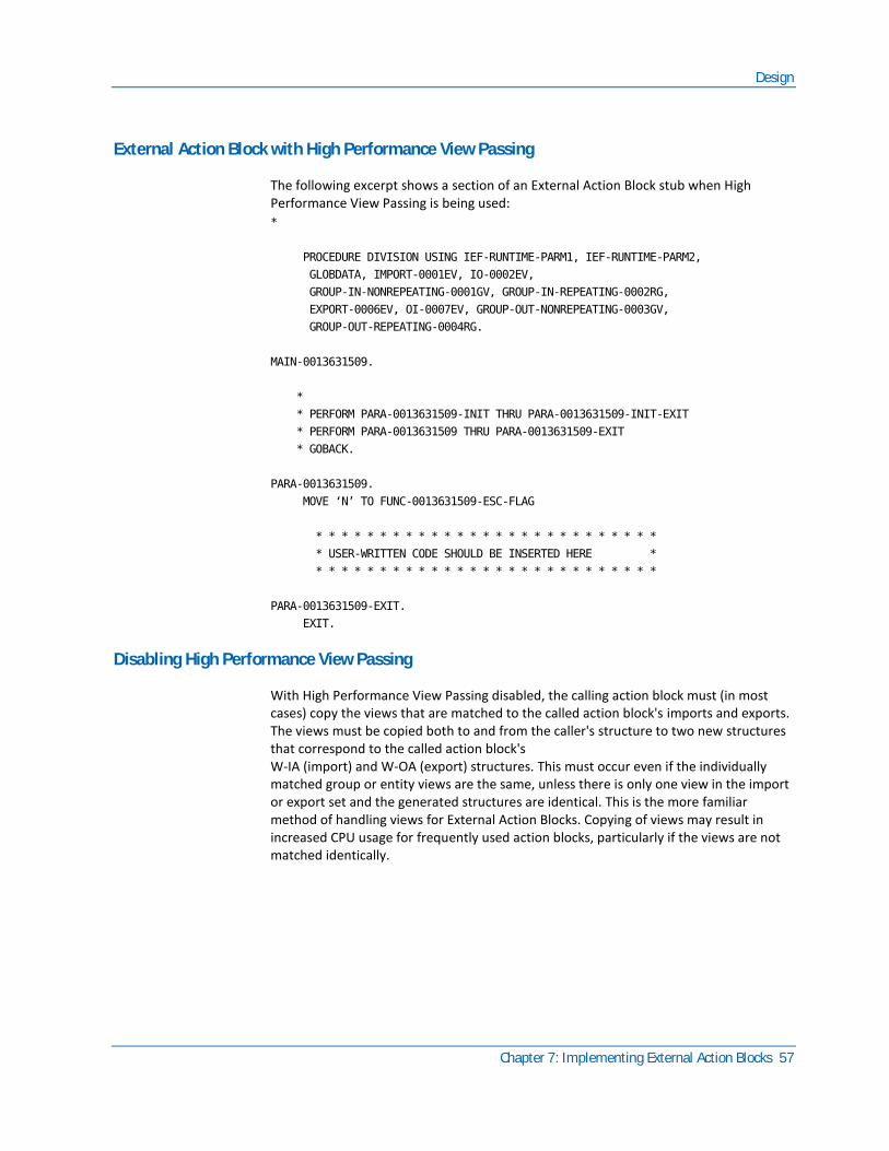
Design
Chapter 7: Implementing External Action Blocks 57
External Action Block with High Performance View Passing
The following excerpt shows a section of an External Action Block stub when High Performance View Passing is being used:
*
PROCEDURE DIVISION USING IEF-RUNTIME-PARM1, IEF-RUNTIME-PARM2,
GLOBDATA, IMPORT-0001EV, IO-0002EV,
GROUP-IN-NONREPEATING-0001GV, GROUP-IN-REPEATING-0002RG,
EXPORT-0006EV, OI-0007EV, GROUP-OUT-NONREPEATING-0003GV,
GROUP-OUT-REPEATING-0004RG.
MAIN-0013631509.
*
* PERFORM PARA-0013631509-INIT THRU PARA-0013631509-INIT-EXIT
* PERFORM PARA-0013631509 THRU PARA-0013631509-EXIT
* GOBACK.
PARA-0013631509.
MOVE ‘N’ TO FUNC-0013631509-ESC-FLAG
* * * * * * * * * * * * * * * * * * * * * * * * * * *
* USER-WRITTEN CODE SHOULD BE INSERTED HERE *
* * * * * * * * * * * * * * * * * * * * * * * * * * *
PARA-0013631509-EXIT.
EXIT.
Disabling High Performance View Passing
With High Performance View Passing disabled, the calling action block must (in most cases) copy the views that are matched to the called action block's imports and exports. The views must be copied both to and from the caller's structure to two new structures that correspond to the called action block's W-IA (import) and W-OA (export) structures. This must occur even if the individually matched group or entity views are the same, unless there is only one view in the import or export set and the generated structures are identical. This is the more familiar method of handling views for External Action Blocks. Copying of views may result in increased CPU usage for frequently used action blocks, particularly if the views are not matched identically.
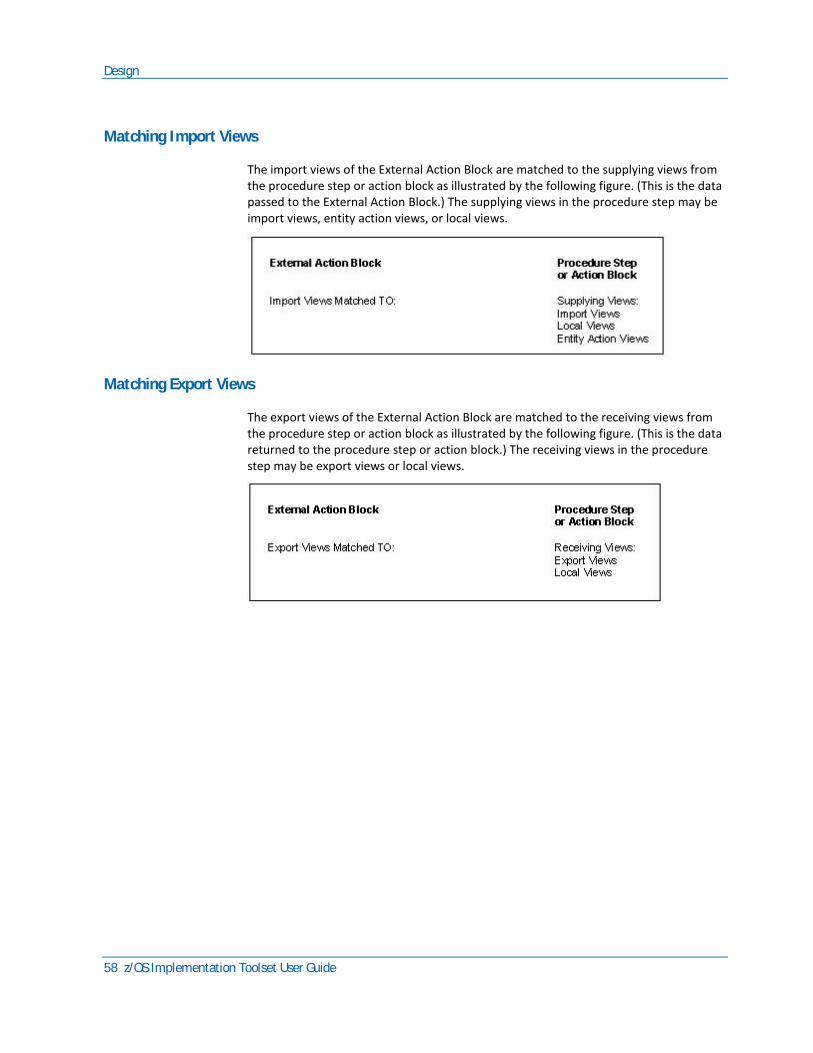
Design
58 z/OS Implementation Toolset User Guide
Matching Import Views
The import views of the External Action Block are matched to the supplying views from the procedure step or action block as illustrated by the following figure. (This is the data passed to the External Action Block.) The supplying views in the procedure step may be import views, entity action views, or local views.
Matching Export Views
The export views of the External Action Block are matched to the receiving views from the procedure step or action block as illustrated by the following figure. (This is the data returned to the procedure step or action block.) The receiving views in the procedure step may be export views or local views.

Design
Chapter 7: Implementing External Action Blocks 59
The following illustration explains the possible supplying and receiving views for view matching in the Procedure Action Diagram. In this figure, the Procedure Step ADD_CUSTOMER calls (uses) the External Action Block
READ_HISTORY.
When you have matched the import and export views of the External Action Block, the USE statement is complete. The procedure used to match the views is described in Design. The USE statement appears in the action diagram of the procedure step or action block. For more information, see the Design Guide.
The following illustration shows a portion of the action diagram for the procedure step ADD_CUSTOMER. This procedure step uses the External Action Block READ_HISTORY.

Construction
60 z/OS Implementation Toolset User Guide
Construction
The following tasks are performed in Construction when building External Action Blocks:
■ Select environment options to indicate the environment parameters required for each Business System.
■ Update packaging information to specify the Dynamic Link option specific for the EAB.
■ Use generation to build the EAB stub.
Environment, Packaging, and Generation tasks are done on the workstation Toolset, CSE Construction Client, or Host Construction, while other tasks are done outside of CA Gen.
For the Toolset, the Environment, Packaging, and Generation operations are available as part of the Construction node under the Diagrams tab of the tree view. Expand the Construction node to locate these operations. A similar set of operations are available in Host Construction and CSE Construction Client.
Environment
For the Toolset, the Dynamic Link Defaults option is located in the MVS Environment Parameters window. A similar set of environment values are available in Host Construction. For the CSE Construction Client, the Dynamic Link Defaults option is located as part of the Environment Properties.
The MVS Environment Parameters can be detailed for each business system defined within a model. These parameters designate the default value for each specific attribute. This set of MVS specific options applies to every component packaged in the business system, including EABs.
The Environment setting for Dynamic Link Defaults for action blocks defines the default value for those action blocks (including EABs) that do not specifically designate a value as to how it should be linked.
Packaging
External Action Blocks are included in the packaging of the procedure step that calls it (either directly or through an action block). Verify that the Dynamic Link option specified for the EAB is appropriate.
The Dynamic Link packaging option is available for applications built for the z/OS execution environments only. The Dynamic Link packaging property of each individual Procedure steps, Screens, and Action Blocks (including EABs) can be set to Default, No, Yes, or Compatibility. When set to Default, the resulting value is derived from the value entered for the Dynamic Link Default option of the Environment Parameters.
Construction
Chapter 7: Implementing External Action Blocks 61
For a business system the following values can be specified:
■ No—indicates that the component will be statically linked into the application.
■ Yes—indicates the component is resolved as the target of a dynamic program call and as such is considered to be dynamic linked at runtime. The component is generated and built so they reside in their own separately loadable executables. These applications are built as DLLs.
■ Compatibility—indicates that the component will be dynamically called at runtime and will reside in a non-DLL module. The Compatibility option uses specific CA Gen runtime to enable DLLs to issue a dynamic program call to non-DLL load modules. This requires that the module issuing the dynamic program call be regenerated and reinstalled. CA Gen allows modules marked for Compatibility to be rebuilt in such a way that they are able to use CA Gen runtime DLLs. This requires that the modules marked for Compatibility be reinstalled and, if necessary, regenerated as specified in z/OS Application Migration section in the Release Summary. RI triggers and action blocks, including EABs, statically called by modules marked for Compatibility must be built using the NODLL compiler option. When these RI triggers and action blocks are also used in Gen applications that are built as DLLs they must be compiled using the DLL option.
For more information, see the section Dynamic Link Options.
Generation
Generation comprises tasks that can take place on a workstation Toolset, CSE Construction Client, or from Host Construction, and tasks that must be performed outside the CA Gen software.
The following tasks are performed using CA Gen:
■ Resolve DBRM
– Workstation toolset—If the external action block contains SQL and the target DBMS is DB2, its DBRMs must be resolved. External Action Block DBRMs are resolved by the Generation Function on the workstation, not on the z/OS IT. To resolve External Action Block DBRMs, select Design, then Action Diagram. Highlight the action diagram name you want and select Detail, External Properties, Add. Input the DBRM name you want, select Close, and then package and generate the remote file as usual. This creates the tokens necessary for the z/OS IT to include the DBRM during the BIND.

Construction
62 z/OS Implementation Toolset User Guide
– Host Construction—If the External Action Block uses embedded SQL and the target DBMS is DB2, CA Gen must be given the names of any database request modules (DBRMs) associated with the External Action Block. The External Action Block Resolution panel is used to identify any DB2 DBRMs for an External Action Block. The panel can also be used to change the name of the External Action Block member. (The member name is the name of the load module that contains the External Action Block.)
■ Generate stub
The following tasks are performed outside of CA Gen:
■ Locate the External Action Block Stub
■ Customize the appropriate external action logic
■ Compile the External Action Block
■ If the External Action Block is statically called by a module marked for Compatibility the EAB must be compiled with the NODLL compile option, if not the EAB must be compiled with the DLL compile option.
■ Link into an External Action Block library
Note: This library must be a data set that has been created as a PDSE (type=library) data set.
Identify Whether the External Action Block Exists
External Action Blocks are identified separately from other CA Gen components in the Install Control Module (ICM), which is at the top of each Load Module Implementation Package (IP), as shown in the following example:
:extern
member=EXTERNAL
name=XTRAN_SAM
TECHSYS=BUS_SYSTEM
:eextern.
Each External Action Block referenced by the load module has an External Action Block identification section. All external Action Blocks in the load module are identified in the same section of the ICM.
Locate the External Action Block Stub
External Action Block code is not included in a remote file created on the code generation platform, so must be moved to your target system as a separate file. If generated on a workstation, the stub is located in the COBOL subdirectory, with the name <stubname>.cbl. If generated by Host Construction, the stub is located in a sequential data set, named userid.<stubname>.cobol.

Construction
Chapter 7: Implementing External Action Blocks 63
After the action block is moved to your target system, it can be stored in any location until the code is written, compiled, and linked. At that point, the EAB load module and DBRM (if there is one) for the External Action Block need to be moved to libraries defined to the Implementation Tool. Ensure that all load libraries used are created as a PDSE (DSNtype=library) data set.
All load modules and DBRMs that are used by an External Action Block must be located in a library defined to the Implementation Tool for the appropriate target environment.
Customize the Appropriate External Action Logic
You are responsible for writing, compiling, and link-editing the external subroutine and making it available to the application. External subroutines can be written in any language but when used by z/OS applications must follow LE linkage conventions. External Action Blocks must follow specific coding conventions so that they interface properly with programs generated through CA Gen.
To help ensure that these requirements are met, CA Gen generates a COBOL program stub you can use as a base for modification. The stub defines the runtime parameters passed from the calling procedure step or action block to the External Action Block. It also defines the import and export views of the External Action Block to match those of the calling procedure step or action block.
You must analyze the External Action Block stub to determine the input and output requirements for your external action.
Copy the generated stub to a separate library before modifying it to prevent an accidental overwrite of the stub. Add the logic needed to meet the specific requirements of your external subroutine. You can use the modified stub to call an existing subroutine or you can include the customized logic in the stub.
Note: If you insert the logic for the external subroutine into the stub, CA Gen does not preserve the changes during regeneration. You must copy any changes into the new External Action Block stub created when the load module is regenerated. For this reason, it is recommended that you put the logic in a subroutine and call the subroutine from the stub rather than insert the logic itself.
External Action Block as Interface to Subroutine
The External Action Block can function as an interface to the external subroutine. Place a CALL statement in the External Action Block stub to access the external subroutine.
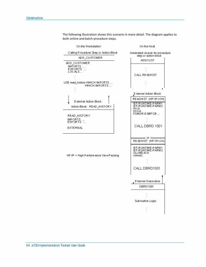
Construction
64 z/OS Implementation Toolset User Guide
The following illustration shows this scenario in more detail. The diagram applies to both online and batch procedure steps.

Construction
Chapter 7: Implementing External Action Blocks 65
In the example, the calling procedure step ADD_CUSTOMER needs to access the customer history database using an external subroutine, DBRD1001. The External Action Block READ_HISTORY defines the views of the CA Gen data needed by DBRD1001 and matches them with the views from ADD_CUSTOMER.
The generated source for the procedure step is called ADDCUST in the example. It contains a statement that calls READHIST.
The External Action Block READHIST is the stub generated by CA Gen and modified by an application developer. READHIST uses the data passed from ADDCUST to call DBRD1001. READHIST reformats the data division components created from the CA Gen views to the structure needed by DBRD1001.
Note: The EXTERNAL statement identifies READ_HISTORY as an External Action Block from which CA Gen generates a stub. The modified stub uses the first eight characters of the External Action Block name, READHIST, as the default member name. The READHIST stub uses the import and export view defined for the READ_HISTORY External Action Block as its input and output parameters. The information in these parameters is used to create the calling interface to the DBRD1001 subroutine.
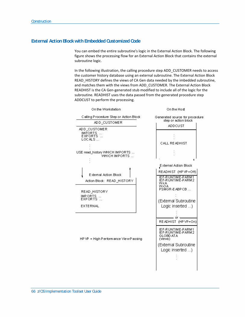
Construction
66 z/OS Implementation Toolset User Guide
External Action Block with Embedded Customized Code
You can embed the entire subroutine's logic in the External Action Block. The following figure shows the processing flow for an External Action Block that contains the external subroutine logic.
In the following illustration, the calling procedure step ADD_CUSTOMER needs to access the customer history database using an external subroutine. The External Action Block READ_HISTORY defines the views of CA Gen data needed by the imbedded subroutine, and matches them with the views from ADD_CUSTOMER. The External Action Block READHIST is the CA Gen-generated stub modified to include all of the logic for the subroutine. READHIST uses the data passed from the generated procedure step ADDCUST to perform the processing.

Construction
Chapter 7: Implementing External Action Blocks 67
After you modify the stub, it becomes the source module for the External Action Block. It must still be compiled and linked before you can install the load module.
Modifying the External Action Block Stub
The procedure step or action block generated through CA Gen passes five parameters to the External Action Block.
■ IEF-RUNTIME-PARM1 (IO-PCB, DFHEIBLK)
■ IEF-RUNTIME-PARM2 (ALT-IO-PCB, DFHCOMMAREA)
■ W-IA (IMPORT-VIEW)
■ W-OA (EXPORT-VIEW)
■ PSMGR-EAB-DATA (PCB-DATA for IMS)
Depending on the TP monitor in use, you may need to modify some of these parameters for proper functioning.
IEF-RUNTIME Parameters
IEF-RUNTIME-PARM1 and IEF-RUNTIME-PARM2 are the first two parameters passed from programs generated through CA Gen. These must be coded on the entry statement of the stub and should always be passed in this order to any subordinate routines called.
For IMS applications, these parameters are the IO-PCB and ALT-IO-PCB. In CICS applications, these parameters are DFHEIBLK and DFHCOMMAREA. These parameters are not used for TSO and batch applications but must still be present.
A special modification is needed for action blocks compiled with the CICS translator (precompiler). If you add CICS commands or need to reference fields in DFHEIBLK, you must use the CICS translator. If so, you must remove IEF-RUNTIME-PARM1 and IEF-RUNTIME-PARM2 from the LINKAGE SECTION and from the USING statement at the beginning of the PROCEDURE DIVISION. The translator inserts DFHEIBLK and DFHCOMMAREA to replace them. Failure to remove them usually results in an ASRA abend on the first move of data to the export views.
If the target TP monitor is CICS, but you have added no CICS commands to the External Action Block and do not reference any fields of the DFHEIBLK, you can compile without using the CICS translator. If you do so, do not remove IEF-RUNTIME-PARM1 and IEF-RUNTIME-PARM2.
Construction
68 z/OS Implementation Toolset User Guide
W-IA and W-OA Parameters
W-IA and W-OA are the import and export views, respectively. The stub must contain data structures that correspond exactly to the import and export views of the External Action Block. The fields in the data structure correspond to attributes in the import and export views of the External Action Block. Each field in a data structure must be preceded by a field defined as PIC X.
Note: If either the import or export views have been modified and you want to replace the previous view declaration with the new one, then the stub must be regenerated. Regeneration is also required if the stub is used for reference and changes to the views were manually made. In this case, the generated code for the calling action diagram could be used instead. If the stub is regenerated, the data and procedure names could be different, as they are not stored on the encyclopedia but generated by an algorithm.
PSMR-EAB-DATA Parameters
PSMGR-EAB-DATA (also called PCB-DATA) is an array of pointers that is used by IMS applications to interface to DL/I databases. For CICS and TSO applications, the array is set to zeroes (null array).
In IMS applications, the array contains the PCB addresses as pointers and is used by External Action Blocks to establish addressability to database PCBs. For each database PCB, code a PCB mask and set its address to the appropriate pointer. For example, assume you have on DL/I database PCB, which is the third PCB in the PSB (following the IO-PCB and ALT-IO-PCB). If you were to code a PCB mask in the LINKAGE SECTION named DB-PCB, you would establish addressability through the statement SET ADDRESS OF DB-PCB TO PSMGR-EABPCB-PTR(3). For more information, see IMS documentation.
In CICS applications, command level calls establish addressability by scheduling the required PCBs in the program. The scheduling does not require the addresses to be passed to each called module because they are implicitly available through the CICS DL/I calls. For more information about CICS DL/I services, see CICS documentation.
In TSO applications, the array is null because CA Gen does not support DL/I databases under TSO.
Using Varying Length Fields
CA Gen generates a two-letter reference (DL) in the EAB to keep track of the actual length of a varying length field. If you are using varying length fields in views to External Action Blocks, the DATA-FILPOST-0011DL field must be set.
Construction
Chapter 7: Implementing External Action Blocks 69
Using Repeating Groups
If the export view of the External Action Block contains a repeating group view, you must indicate the number of occurrences returned by setting the maximum field. This is a numeric field that immediately precedes the repeating group, and which has a name that ends with the letters MA (for Maximum). The field is also redefined as alphabetic using a name that ends with the letters MX. If you use multiple repeating groups, you have multiple maximum fields, one for each group.
You are responsible for keeping track of how many occurrences are returned and placing that count in the maximum field. Failure to do so results in the calling procedure or action block behaving as if the External Action Block returned no data in the repeating group.
The status of the repeating group is generated and placed in the External Action Block stub as a two-letter reference. These status references are described in the following table:
Status Description
AC Active/Inactive flag for line item in group view. Used by CA Gen.
AS Attribute status. Used by CA Gen.
FL View full. Used by CA Gen in action blocks (not EABs).
PS Subscript/pointer for repeating group view. Used by CA Gen.
RF View referenced. Used by CA Gen in action blocks (not EABs).
Compile the External Action Block
You need to compile and link-edit the modified External Action Block stub outside CA Gen.
Construction
70 z/OS Implementation Toolset User Guide
Load Module Structure
Executable load modules for an application are created during Construction. The system generation tools create a COBOL source module for the procedure step or action block and place the source code in a library you specify. The name of this library is what you specified as the location for Source Lib.
When you compile and link the modified External Action Block stub and external subroutine, together they become the External Action Block.
When you use CA Gen to install (compile, link-edit, and bind) a load module that contains a procedure step or action block that uses the External Action Block, the link-editor resolves the reference to the External Action Block. How this reference is resolved depends on the type of call used to invoke the External Action Block as well as how it was compiled and linked. The EAB's Dynamically Link packaging property determines if the EAB is statically included in the resulting executable (composite) load module or is invoked using a dynamic call.
When the EAB is statically included in the resulting executable (composite) load module and the composite load module is a module marked for Compatibility, ensure the EAB is compiled using the NODLL compiler option and that the NCAL linked External Action Block load module is placed in a library in the Implementation Toolset's Static External Action Block Load libraries panel before the load module is installed.
When the EAB is statically included in the resulting executable (composite) load module and the composite load module is not a module marked for Compatibility, ensure the EAB is compiled using the DLL compiler option and that the NCAL linked External Action Block load module is placed in a library in the Implementation Toolset's External Action Block Load libraries location before the load module is installed.
Place any related DBRMs in the Implementation Toolset's External Action Block DBRM library. The composite load module is stored in the Executable Load Module library. The composite load module contains the procedure step (or action block), the modified External Action Block stub, and the external subroutines that the stub may call.
When you invoke the EAB using a dynamic program call, the EAB resides in its own separate executable module. In this case, you must build the load module containing the EAB as a DLL unless the Dynamically Link packaging property associated with the EAB has been set (or derived) to Compatibility. An EAB that has a Dynamically Link packaging property of Compatibility can be rebuilt as a non-DLL z/OS load module or can be used as built by a release of Gen before release 7.0. For more information, see the section Dynamic Link Options.
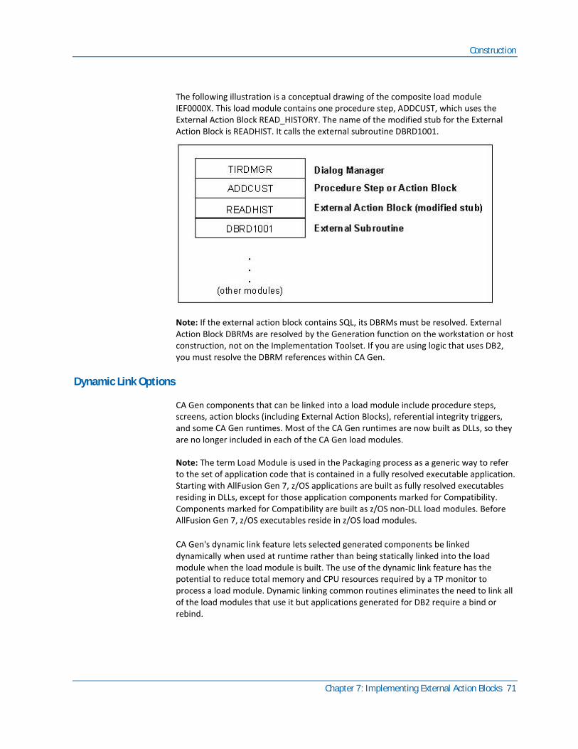
Construction
Chapter 7: Implementing External Action Blocks 71
The following illustration is a conceptual drawing of the composite load module IEF0000X. This load module contains one procedure step, ADDCUST, which uses the External Action Block READ_HISTORY. The name of the modified stub for the External Action Block is READHIST. It calls the external subroutine DBRD1001.
Note: If the external action block contains SQL, its DBRMs must be resolved. External Action Block DBRMs are resolved by the Generation function on the workstation or host construction, not on the Implementation Toolset. If you are using logic that uses DB2, you must resolve the DBRM references within CA Gen.
Dynamic Link Options
CA Gen components that can be linked into a load module include procedure steps, screens, action blocks (including External Action Blocks), referential integrity triggers, and some CA Gen runtimes. Most of the CA Gen runtimes are now built as DLLs, so they are no longer included in each of the CA Gen load modules.
Note: The term Load Module is used in the Packaging process as a generic way to refer to the set of application code that is contained in a fully resolved executable application. Starting with AllFusion Gen 7, z/OS applications are built as fully resolved executables residing in DLLs, except for those application components marked for Compatibility. Components marked for Compatibility are built as z/OS non-DLL load modules. Before AllFusion Gen 7, z/OS executables reside in z/OS load modules.
CA Gen's dynamic link feature lets selected generated components be linked dynamically when used at runtime rather than being statically linked into the load module when the load module is built. The use of the dynamic link feature has the potential to reduce total memory and CPU resources required by a TP monitor to process a load module. Dynamic linking common routines eliminates the need to link all of the load modules that use it but applications generated for DB2 require a bind or rebind.
Construction
72 z/OS Implementation Toolset User Guide
The key features and requirements are:
■ Only procedure steps, action blocks, and screens can be linked dynamically.
■ Each dynamic linked module must be a fully resolved module.
■ If this fully resolved module is a DLL, this means Referential Integrity triggers, other action blocks statically linked with a procedure step, screen, or action block must be compiled as DLL and with the applicable CA Gen runtimes must be linked into each dynamic linked DLL.
■ If this fully resolved module is a module marked for Compatibility, this means Referential Integrity triggers, other action blocks statically linked with a procedure step, screen, or action block must be compiled as NODLL and with the applicable CA Gen runtimes must be linked into the Compatibility load module.
■ The dynamically link packaging property of individual procedure steps, screens, and action blocks can be set to Default. Default indicates that the value of the dynamically link property for that component is determined by the corresponding default setting, which is established at the business system level.
■ Marking a module for Compatibility causes its calling module to be generated and installed so that it processes the call using a module provided as part of the CA Gen runtime. The runtime code performs the dynamic program call to the non-DLL load module. In the cases where a module marked for Compatibility issues a dynamic program call to another non-DLL dynamic load module, only the module issuing the first dynamic program call to a Compatibility module requires generation and installation.
■ Applications that run under TSOAE and contain modules marked for Compatibility cannot dynamically call modules built with a release prior to AllFusion Gen 7.6.
■ Enhanced Map Block Mode applications containing screens marked for Compatibility cannot dynamically call screen managers built with a release before AllFusion Gen 7.6.
■ Modules marked for Compatibility must follow standard OS or LE linkage conventions and must operate in the same AMODE as the caller. These modules must be non-DLL and must be stand-alone, fully resolved programs, eligible for a dynamic, OS style call.
■ The ability to call a procedure step, action block, or screen dynamically allows application changes to become effective without having to link every load module using these modules. However, changes made to a module that uses DB2 SQL requires that the DB2 plan corresponding to the load module containing that module be rebound.
■ In CICS, a PPT entry is required for each module called dynamically. For more information about defining CICS programs, see CICS documentation.
Construction
Chapter 7: Implementing External Action Blocks 73
Compile and Link-Edit External Action Block
You are responsible for compiling and link-editing the External Action Block. The EAB can either be statically linked (included in another module) or dynamically linked (its own module).
A static EAB can be called from a Compatibility module, a static module or a dynamic DLL. When linking a static EAB, do not link any DL/I, COBOL, DB2, CICS, or ISPF system modules into the load module for the External Action Block. The installation process links these modules into your final executable load module.
1. When the static EAB is called from a Compatibility module and the statically linked EAB is to be built, you must use the following compile and link options:
■ Compile the EAB with the options OPT, NOSEQ, NODLL, NODYNAM, RENT, and NOEXPORTALL.
■ Link-edit the EAB with the options RENT, REUS, NCAL, and DYNAM(NO).
■ The NCAL linked EAB must be placed in a library in the Static External Action Block libraries panel.
2. When the static EAB is called from either a static module or a dynamic DLL, the statically linked EAB must be built using the following compile and link options:
■ Compile the EAB with the options OPT, NOSEQ, DLL, NODYNAM, RENT and NOEXPORTALL.
■ Link-edit the EAB with the options RENT, REUS, NCAL, and DYNAM(NO).
■ The NCAL linked EAB must be placed in a library in the External Action Block libraries panel.
When the EAB has been packaged with Dynamically Link option of Yes, the EAB must be built as a DLL to be invoked by a generated application. Any module called by an EAB built as a DLL must also be a DLL. DLLs require that modules be bound as objects in Program Management Format 3 (PM3) and must reside in a PDSE library.
Important! Since External libraries are still in SYSLIB concatenation, if using the z/OS Library feature, you must ensure that none of the External System or External Action Block libraries contains an NCAL module named same as the called zLIB action blocks. Otherwise these zLIB action blocks will be statically included to the caller during linkedit through auto-call.
To build the EAB as a DLL, use the following compile and link edit options:
■ Compile the EAB with the options OPT, NOSEQ, DLL and EXPORTALL in addition to the default compiler options.
Note: Selecting DLL forces the RENT and NODYNAM compiler options to also be used.

Installation
74 z/OS Implementation Toolset User Guide
■ Link the EAB with the options RENT, REUS and DYNAM(DLL).
Note: Do not confuse the compiler option NODYNAM with the link-edit option DYNAM(DLL). The two are not the same as one is a compiler option while the other is link option.
Copy the EAB DLL to a dataset that will allow the DLL to be resolved in the target environment. For TSO and IMS this is a dataset that is part of the STEPLIB concatenation. For CICS this is a dataset that is part of the DFHRPL concatenation. Also, if target environment is CICS, a CICS program definition must be added for the resulting EAB DLL.
For information about DLLs, see IBM's Language Environment and the Program Management (Binder) documentation.
When the EAB has an associated Dynamically Link Packaging property set to Compatibility, the EAB must be built as a non-DLL. Modules marked for Compatibility must follow standard OS or LE linkage conventions and must operate in the same AMODE as the caller. These modules may not be DLLs and must be fully resolved programs, eligible for being the target of an OS style dynamic program call.
To build the EAB as a non-DLL, use the following compile and link-edit options:
■ Compile the EAB with the options OPT, NOSEQ, NODLL, RENT in addition to the default compiler options.
■ Link-edit the EAB with the options RENT, REUS.
■ Copy the non-DLL EAB to a dataset that will allow the DLL to be resolved in the target environment. For TSO and IMS this is a dataset that is part of the STEPLIB concatenation. For CICS this is a dataset that is part of the DFHRPL concatenation. Also, if target environment is CICS, a CICS program definition must be added for the resulting non-DLL EAB.
Installation
If the generated application contains a statically linked EAB, you must install (compile and link) the application to resolve any reference to the EAB. For more information on installing the generated application, see the chapter Creating Executable Load Modules.
Transfer the Remote File
If you generate your application on a workstation, the remote file resides in the COBOL subdirectory, with the name <loadmodule>.rmt.
If you generate on Host Construction, the remote file resides in <userid>.<loadmodule>.reminst.

Installation
Chapter 7: Implementing External Action Blocks 75
Identify Whether the External Action Block Exists
External Action Blocks are identified separately from other CA Gen components in the Install Control Module (ICM), which is at the top of each Load Module Implementation Package (IP), as shown in the following example:
:extern
member=EXTERNAL
name=XTRAN_SAM
TECHSYS=BUS_SYSTEM
:eextern.
There is an External Action Block identification section for each External Action Block referenced by the load module. All External Action Blocks in the load module are identified in the same section of the ICM.
Install the Load Module
Follow the steps detailed in the chapter "Creating Executable Load Modules" to install the remote file.


Chapter 8: Testing Applications 77
Chapter 8: Testing Applications
This chapter describes how CA Gen provides an Application Test Facility that allows you to test new systems or changes to systems in a TSO testing environment that simulates your target production environment. Online (IMS, CICS, TSO) and batch applications can be tested with the Application Test Facility. To test an application system, you generate Implementation Packages (IPs) on the code generation platform, move the IPs to the target system, install the IPs into the testing environment, and execute the test. During the test, you see how your system behaves at runtime.
CA Gen also provides a Debug Trace Facility that can be used to debug programs generated through CA Gen at the model input level. With Debug Trace, you are able to execute and debug CA Gen action diagrams as opposed to debugging the COBOL code that is generated for them. As your generated application executes, you see the sequence of action block calls and action diagram statements being executed. This allows you to step through the execution of your application. You can also display and modify the views (data stores) and system variables for each action diagram. To use the Debug Trace Facility, you must select debug support when you generate your application.
You can execute the Debug Trace Facility under CICS to test CICS online transactions and Distributed Process Server (DPS) applications. This facility allows the developer to test the application in the target environment.
For all other types of applications (IMS, TSO and batch), testing with the Debug Trace Facility must be done within the Application Test Facility.
Application Test Facility Considerations
The TSOAE environment used by the Application Test Facility was implemented as a 31-bit, LE compliant application. The use of 24-bit storage was changed to be limited to those TSO and I/O functions that require being addressed below the 16-MB line. This version of TSOAE provides virtual storage constraint relief for testing and implementing large CA Gen applications within TSO and batch.
The Application Test Facility does not support external subroutine logic such as DL/I calls, IMS calls, or CICS calls.
Only DB2 databases can be updated during test executions.
CICS Debug Trace Facility Considerations
78 z/OS Implementation Toolset User Guide
You have two ways to test applications that use DL/I, IMS, or CICS calls:
■ Create CA Gen procedure steps without the USE statements that call the external logic. Then generate and test CA Gen load modules. After the load modules have been debugged, add the USE statements to your action diagrams.
■ Create CA Gen procedure steps, including the USE statements in your action diagrams. Create stubs for the external routines that do not use DL/I, IMS, or CICS calls. Then generate and test CA Gen load modules. After the load modules have been debugged, add the DL/I, IMS, or CICS calls to the stubs.
When testing batch applications, it is important to consider the amount of test data used. The Application Test Facility executes online, so it is recommended you use a small volume of data when testing batch applications.
CICS Debug Trace Facility Considerations
The Debug Trace Facility may be executed under CICS to test CICS online and server applications. Under CICS, external subroutine logic such as DL/I and CICS calls may be tested. The Temporary Storage Queue (TSQ) Profile Manager can be used too. Be aware that using the Debug Trace Facility under CICS may result in long-running transactions in your CICS region.
Also note that CICS applications using runtimes from AllFusion Gen 7 or later no longer require a Transaction Work Area so the transaction's definition TWAsize can be set to zero.
Trace Facility Display Interface
The Trace Facility Display Interface (TFDI) is a transaction that is used to display a panel of debug information when the Debug Trace Facility is used to trace CICS online and server applications. This transaction must be installed to operate the Debug Trace Facility under CICS. The TFDI transaction still requires a TWAsize of 1200 bytes.
Generate IPs for Testing
Chapter 8: Testing Applications 79
Generate IPs for Testing
Before you can test an application system, you must generate the load modules for the transactions you want to test. When determining which load modules must be generated, consider the following:
■ Generate all load modules you need for your test. If you are testing the flow between two procedure steps, be sure that both procedure steps have been generated.
■ During testing, if you attempt to access a load module that has not been generated, the test fails.
■ If you are generating load module components separately, be sure that all required components within a load module are generated. If any component is not generated and is not Dynamically called, the load module cannot be installed. The install will fail because the link-edit step will have unresolved references.
■ To test any part of a multistep procedure, you must always generate the first procedure step as well as the procedure steps you intend to test. This is because the first procedure step provides the access to all other procedure steps in the procedure.
Generate with Debug Support
The Debug Trace Facility lets you debug programs generated through CA Gen at the CA Gen diagram level. As your program executes, you see the sequence of action block calls and the sequence of action diagram statements being executed. You can also display and modify the views and the system variables for each action diagram.
If you intend to test a load module or its components with the Debug Trace Facility, you must generate debug support. Debug support is the code the CA Gen generates to drive the Debug Trace Facility.
Install in the Test Environment
The following section includes information concerning the Application Test Facility, CICS testing, and creating the executable.
Application Test Facility
To test using the Application Test Facility, specify IEFAE as the target environment. On the Host, you may also select Target TSO Test Facility as a Generation option.

Execute Test Under CICS
80 z/OS Implementation Toolset User Guide
CICS Testing
To test using the Debug Trace Facility under CICS, specify CICS as the target environment. The application, the Trace Facility Display Interface (TFDI), the Debug Trace Facility (DTF) load modules, and the TIRCRUNC DLL must be installed in the CICS region.
Create the Executable
The install function performs a final link-edit that creates executable load modules. All external references are resolved at this time.
Execute Test Under CICS
You perform the following activities to test under the CICS Debug Test Facility:
■ Install your DPS application
■ Install the Trace Facility Display Interface (TFDI)
■ Install the Debug Trace Facility (DTF)
■ Install the TIRCRUNC runtime DLL
All modules must be installed in the CICS region. The TFDI and DTF modules and the TIRCRUNC DLL are located in the CA Gen load library.
CICS DTF User Interface
The DTF user interface provides the ability to control the trace facility by specifying the transaction to be placed in the trace mode. DTF manipulates the debug control queue by adding or removing records, thereby placing the transactions in or out of the trace mode. While the Debug Trace Facility is on, all executed procedure steps and action blocks that were generated with the debug option are traced.
Starting DTF
You start the Debug Trace Facility by executing a CICS transaction. The suggested name of this transaction is DTF. However, this name may be changed when CA Gen is first installed. Contact your systems support staff to determine the transaction name at your site.
This documentation assumes it is DTF. The DTF command has the following format:
DTF command transaction <user ID> <terminal ID>
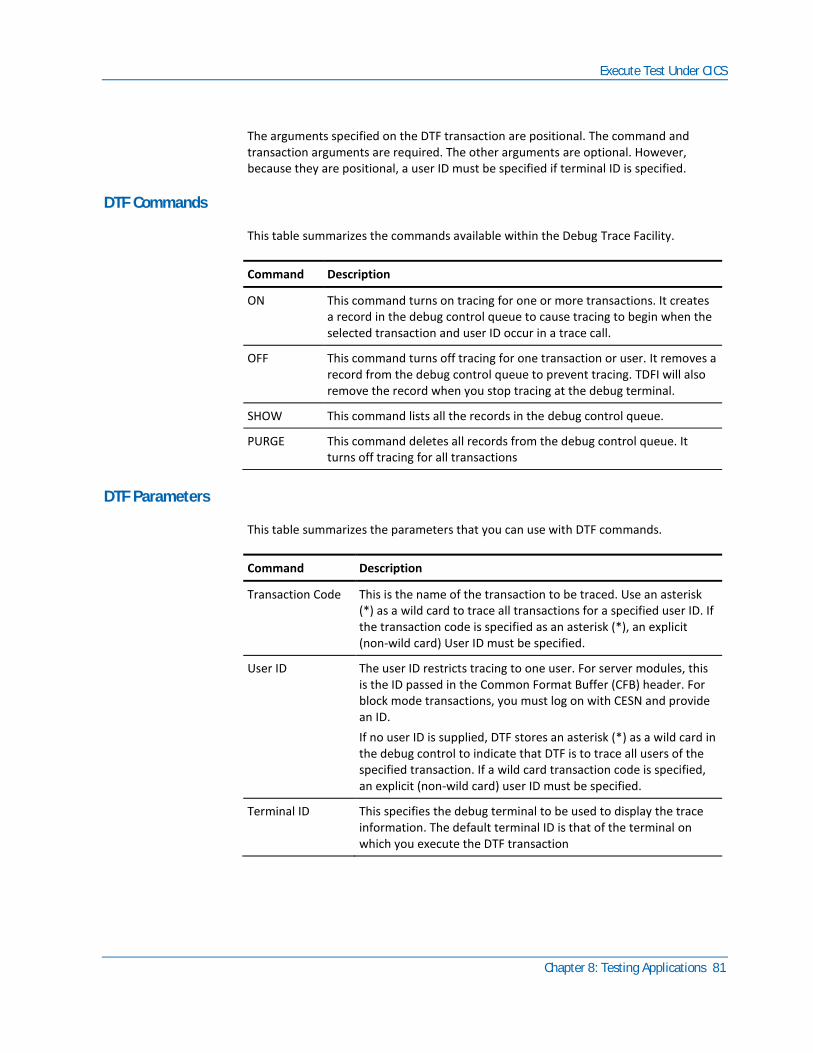
Execute Test Under CICS
Chapter 8: Testing Applications 81
The arguments specified on the DTF transaction are positional. The command and transaction arguments are required. The other arguments are optional. However, because they are positional, a user ID must be specified if terminal ID is specified.
DTF Commands
This table summarizes the commands available within the Debug Trace Facility.
Command Description
ON This command turns on tracing for one or more transactions. It creates a record in the debug control queue to cause tracing to begin when the selected transaction and user ID occur in a trace call.
OFF This command turns off tracing for one transaction or user. It removes a record from the debug control queue to prevent tracing. TDFI will also remove the record when you stop tracing at the debug terminal.
SHOW This command lists all the records in the debug control queue.
PURGE This command deletes all records from the debug control queue. It turns off tracing for all transactions
DTF Parameters
This table summarizes the parameters that you can use with DTF commands.
Command Description
Transaction Code This is the name of the transaction to be traced. Use an asterisk (*) as a wild card to trace all transactions for a specified user ID. If the transaction code is specified as an asterisk (*), an explicit (non-wild card) User ID must be specified.
User ID The user ID restricts tracing to one user. For server modules, this is the ID passed in the Common Format Buffer (CFB) header. For block mode transactions, you must log on with CESN and provide an ID.
If no user ID is supplied, DTF stores an asterisk (*) as a wild card in the debug control to indicate that DTF is to trace all users of the specified transaction. If a wild card transaction code is specified, an explicit (non-wild card) user ID must be specified.
Terminal ID This specifies the debug terminal to be used to display the trace information. The default terminal ID is that of the terminal on which you execute the DTF transaction
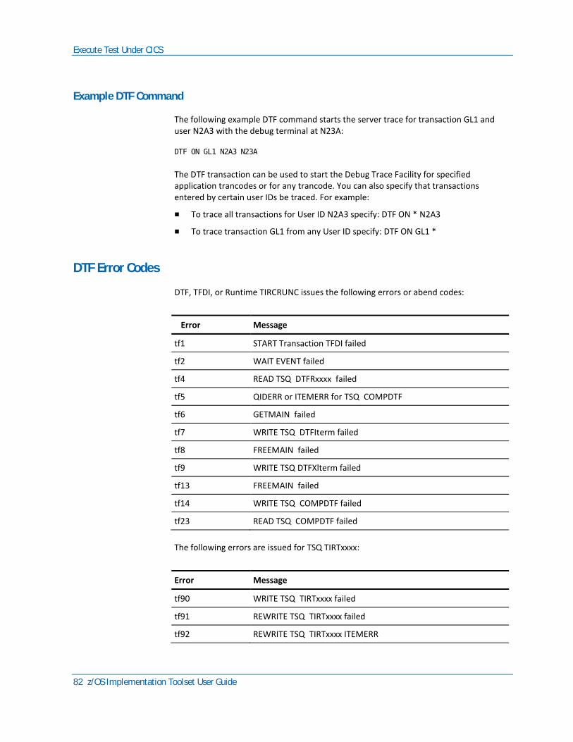
Execute Test Under CICS
82 z/OS Implementation Toolset User Guide
Example DTF Command
The following example DTF command starts the server trace for transaction GL1 and user N2A3 with the debug terminal at N23A:
DTF ON GL1 N2A3 N23A
The DTF transaction can be used to start the Debug Trace Facility for specified application trancodes or for any trancode. You can also specify that transactions entered by certain user IDs be traced. For example:
■ To trace all transactions for User ID N2A3 specify: DTF ON * N2A3
■ To trace transaction GL1 from any User ID specify: DTF ON GL1 *
DTF Error Codes
DTF, TFDI, or Runtime TIRCRUNC issues the following errors or abend codes:
Error Message
tf1 START Transaction TFDI failed
tf2 WAIT EVENT failed
tf4 READ TSQ DTFRxxxx failed
tf5 QIDERR or ITEMERR for TSQ COMPDTF
tf6 GETMAIN failed
tf7 WRITE TSQ DTFIterm failed
tf8 FREEMAIN failed
tf9 WRITE TSQ DTFXlterm failed
tf13 FREEMAIN failed
tf14 WRITE TSQ COMPDTF failed
tf23 READ TSQ COMPDTF failed
The following errors are issued for TSQ TIRTxxxx:
Error Message
tf90 WRITE TSQ TIRTxxxx failed
tf91 REWRITE TSQ TIRTxxxx failed
tf92 REWRITE TSQ TIRTxxxx ITEMERR
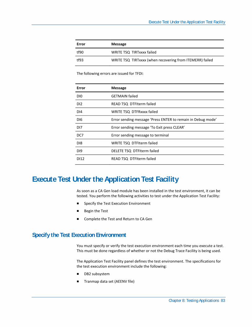
Execute Test Under the Application Test Facility
Chapter 8: Testing Applications 83
Error Message
tf90 WRITE TSQ TIRTxxxx failed
tf93 WRITE TSQ TIRTxxxx (when recovering from ITEMERR) failed
The following errors are issued for TFDI:
Error Message
DI0 GETMAIN failed
DI2 READ TSQ DTFIterm failed
DI4 WRITE TSQ DTFRxxxx failed
DI6 Error sending message ‘Press ENTER to remain in Debug mode’
DI7 Error sending message ‘To Exit press CLEAR’
DC7 Error sending message to terminal
DI8 WRITE TSQ DTFIterm failed
DI9 DELETE TSQ DTFIterm failed
DI12 READ TSQ DTFIterm failed
Execute Test Under the Application Test Facility
As soon as a CA Gen load module has been installed in the test environment, it can be tested. You perform the following activities to test under the Application Test Facility:
■ Specify the Test Execution Environment
■ Begin the Test
■ Complete the Test and Return to CA Gen
Specify the Test Execution Environment
You must specify or verify the test execution environment each time you execute a test. This must be done regardless of whether or not the Debug Trace Facility is being used.
The Application Test Facility panel defines the test environment. The specifications for the test execution environment include the following:
■ DB2 subsystem
■ Tranmap data set (AEENV file)

Execute Test Under the Application Test Facility
84 z/OS Implementation Toolset User Guide
■ Application load library
■ Test SYSLIBs
■ End function key assignment
DB2 Subsystem
The DB2 subsystem is the DB2 SYSID of the DB2 system to access for the test. You may want to use a DB2 subsystem that is not used for production. This is especially important if you are testing changes to a program that is also running in production.
Application Load Library
The Application Load Library is the load library containing the load modules to be tested.
Test SYSLIBS
Test SYSLIBS must be specified if your application includes external routines that use dynamically called system routines. The test SYSLIBS are the libraries where the dynamically called system routines are found. Up to four SYSLIBS can be specified.
External files must be allocated outside of CA Gen. Using a TSO CLIST is a convenient way to allocate the files. Execute the CLIST on the TSO COMMAND line:
TSO ex clist dataset_member_name for PDS CLISTS
TSO ex clist dataset_name for SEQ CLISTS
End Function Key Assignment
The End function key assignment lets you specify the key to be used to return to a clear screen and end the test session.
Don't use a function key that is used by your application system. The End function key assignment overrides the function keys assigned within your application. For example, if your application uses F15 to return to a master menu and you assign F15 (the default) as the End function key, the Test Facility recognizes F15 as an End command only. When you press F15 from an application screen, the Test Facility does not return to the master menu.
Begin Testing
After you specify the test execution environment, you can begin testing the application immediately. To begin the test, press Enter from the Specify Test Execution Environment panel. A clear screen appears.

Execute Test Under the Application Test Facility
Chapter 8: Testing Applications 85
Online Load Module
To start the test session for an online load module, type the clear screen transaction code of the first transaction you want to test. Verify the load module for the transaction is installed. CA Gen does not recognize the transaction code if the load module is not installed.
Note: You must begin a test of a multistep, online procedure by entering the transaction code for the first procedure step.
The Testing Facility begins simulating your application. During the test, you can use any of the application functions whose load modules are installed in the testing environment.
You can return to a clear screen from an application screen at any time. From a clear screen, you can test another transaction by entering its transaction code or you can exit the test. To exit the test, press End.
If you are not using the Debug Trace Facility, the Test Facility displays the application screens exactly as they appear in a production environment. If you are using the Debug Trace Facility, several debug panels are displayed in addition to your application screens. Later sections of this chapter define the debug panels and how you use them.
Batch Job
To start the test session for a batch job, type the load module name as the input transaction code. Because it is an online test, it is recommended that you use a small volume of data during testing.
Note: The Test Facility does not support DL/I access by external action blocks.
For batch procedures, the Batch Manager uses three special files. These files are allocated with dataset names prefix.IEF.TIRxxxF. The value for prefix is specified during host installation.
After executing the test, you can examine the TIRMSGF and TIRERRF files to view the results. The TIRIOVF file is cleared when a procedure completes successfully.
When a procedure has completed successfully, an end of job message appears on the screen. If the procedure fails, CA Gen runtime error messages are written to the screen in the same manner as for an online procedure step failure. In either case, clear the screen before initiating another test.

Execute Test Under the Application Test Facility
86 z/OS Implementation Toolset User Guide
Rerunning a Failed Batch Job
You can restart a failed batch procedure step under the Test Facility by entering the load module name of the failed procedure step. TIRIOVF contains the import view that was passed on the previous transfer (from another step or itself). You must restore any files controlled by external action blocks.
Use the following procedure to rerun a failed batch job from the beginning while in the Test Facility.
Follow these steps:
1. Back out the changes to the DB2 tables and to any files controlled by external action blocks.
2. Run the CLEARIOV CLIST to reset the TIRIOVF file. Executing a procedure without clearing the TIRIOVF first, results in a fatal error because the Batch Manager expects to restart a different step. Execute the CLIST by entering TSO CLEARIOV on the TSO COMMAND line when the Specify Test Execution Environment Panel is displayed.
3. Enter the load module name of the first procedure step again.
Complete Testing and Return to CA Gen
You can return to a clear screen from an application at any time by pressing the End key that you specified for the test execution environment. From a clear screen, you can test another transaction by entering its transaction code or you can exit the test by pressing End.
After executing the test of a batch procedure, you can examine the TIRMSGF file to view the results. The TIRIOVF file is cleared when a procedure completes successfully. When a batch procedure completes successfully, an end of job message appears on the screen.
Abnormal Ends
Abnormal endings (abends) are handled by the Dialog Manager, which is part of every online load module generated through CA Gen. If a batch procedure fails, a failure message is written to the screen in the same manner as an online procedure failure.
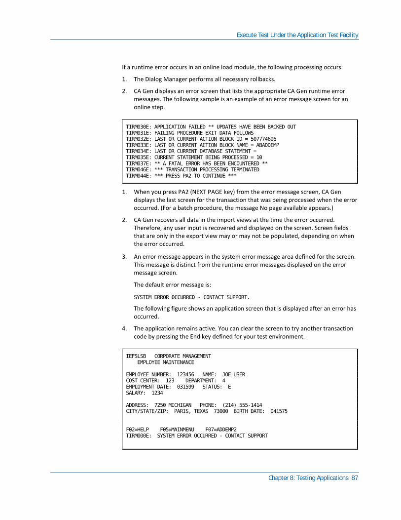
Execute Test Under the Application Test Facility
Chapter 8: Testing Applications 87
If a runtime error occurs in an online load module, the following processing occurs:
1. The Dialog Manager performs all necessary rollbacks.
2. CA Gen displays an error screen that lists the appropriate CA Gen runtime error messages. The following sample is an example of an error message screen for an online step.
TIRM030E: APPLICATION FAILED ** UPDATES HAVE BEEN BACKED OUT TIRM031E: FAILING PROCEDURE EXIT DATA FOLLOWS TIRM032E: LAST OR CURRENT ACTION BLOCK ID = 507774696 TIRM033E: LAST OR CURRENT ACTION BLOCK NAME = ABADDEMP TIRM034E: LAST OR CURRENT DATABASE STATEMENT = TIRM035E: CURRENT STATEMENT BEING PROCESSED = 10 TIRM037E: ** A FATAL ERROR HAS BEEN ENCOUNTERED ** TIRM046E: *** TRANSACTION PROCESSING TERMINATED TIRM044E: *** PRESS PA2 TO CONTINUE ***
1. When you press PA2 (NEXT PAGE key) from the error message screen, CA Gen displays the last screen for the transaction that was being processed when the error occurred. (For a batch procedure, the message No page available appears.)
2. CA Gen recovers all data in the import views at the time the error occurred. Therefore, any user input is recovered and displayed on the screen. Screen fields that are only in the export view may or may not be populated, depending on when the error occurred.
3. An error message appears in the system error message area defined for the screen. This message is distinct from the runtime error messages displayed on the error message screen.
The default error message is:
SYSTEM ERROR OCCURRED - CONTACT SUPPORT.
The following figure shows an application screen that is displayed after an error has occurred.
4. The application remains active. You can clear the screen to try another transaction code by pressing the End key defined for your test environment.
IEFSLSB CORPORATE MANAGEMENT EMPLOYEE MAINTENANCE EMPLOYEE NUMBER: 123456 NAME: JOE USER COST CENTER: 123 DEPARTMENT: 4 EMPLOYMENT DATE: 031599 STATUS: E SALARY: 1234 ADDRESS: 7250 MICHIGAN PHONE: (214) 555-1414 CITY/STATE/ZIP: PARIS, TEXAS 73000 BIRTH DATE: 041575 F02=HELP F05=MAINMENU F07=ADDEMP2 TIRM000E: SYSTEM ERROR OCCURRED - CONTACT SUPPORT
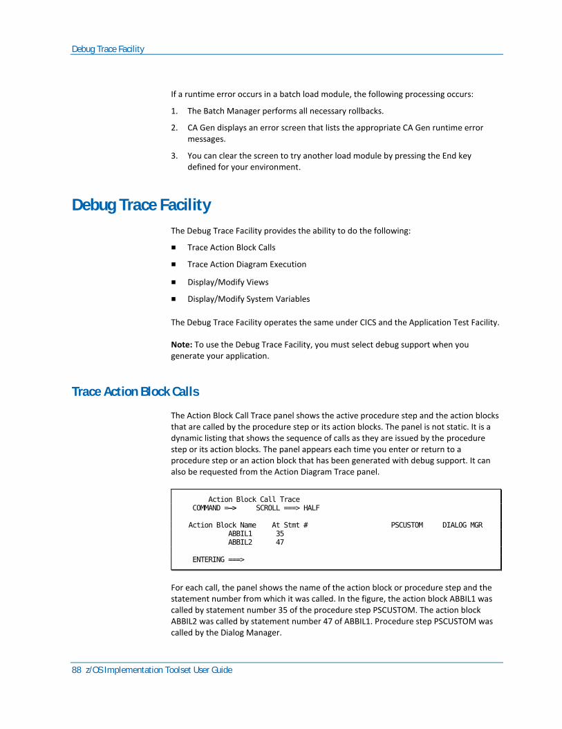
Debug Trace Facility
88 z/OS Implementation Toolset User Guide
If a runtime error occurs in a batch load module, the following processing occurs:
1. The Batch Manager performs all necessary rollbacks.
2. CA Gen displays an error screen that lists the appropriate CA Gen runtime error messages.
3. You can clear the screen to try another load module by pressing the End key defined for your environment.
Debug Trace Facility
The Debug Trace Facility provides the ability to do the following:
■ Trace Action Block Calls
■ Trace Action Diagram Execution
■ Display/Modify Views
■ Display/Modify System Variables
The Debug Trace Facility operates the same under CICS and the Application Test Facility.
Note: To use the Debug Trace Facility, you must select debug support when you generate your application.
Trace Action Block Calls
The Action Block Call Trace panel shows the active procedure step and the action blocks that are called by the procedure step or its action blocks. The panel is not static. It is a dynamic listing that shows the sequence of calls as they are issued by the procedure step or its action blocks. The panel appears each time you enter or return to a procedure step or an action block that has been generated with debug support. It can also be requested from the Action Diagram Trace panel.
Action Block Call Trace COMMAND =—> SCROLL ===> HALF Action Block Name At Stmt # PSCUSTOM DIALOG MGR ABBIL1 35 ABBIL2 47 ENTERING ===>
For each call, the panel shows the name of the action block or procedure step and the statement number from which it was called. In the figure, the action block ABBIL1 was called by statement number 35 of the procedure step PSCUSTOM. The action block ABBIL2 was called by statement number 47 of ABBIL1. Procedure step PSCUSTOM was called by the Dialog Manager.
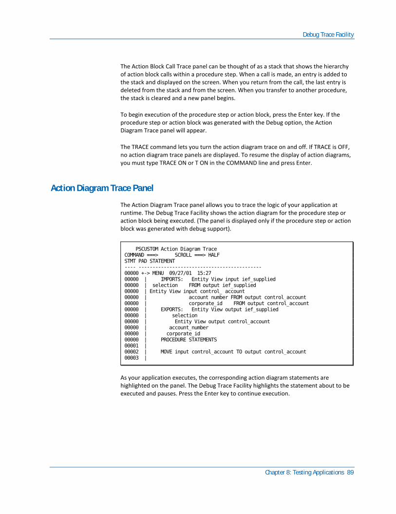
Debug Trace Facility
Chapter 8: Testing Applications 89
The Action Block Call Trace panel can be thought of as a stack that shows the hierarchy of action block calls within a procedure step. When a call is made, an entry is added to the stack and displayed on the screen. When you return from the call, the last entry is deleted from the stack and from the screen. When you transfer to another procedure, the stack is cleared and a new panel begins.
To begin execution of the procedure step or action block, press the Enter key. If the procedure step or action block was generated with the Debug option, the Action Diagram Trace panel will appear.
The TRACE command lets you turn the action diagram trace on and off. If TRACE is OFF, no action diagram trace panels are displayed. To resume the display of action diagrams, you must type TRACE ON or T ON in the COMMAND line and press Enter.
Action Diagram Trace Panel
The Action Diagram Trace panel allows you to trace the logic of your application at runtime. The Debug Trace Facility shows the action diagram for the procedure step or action block being executed. (The panel is displayed only if the procedure step or action block was generated with debug support).
PSCUSTOM Action Diagram Trace COMMAND ===> SCROLL ===> HALF STMT PAD STATEMENT ---- -------------------------------------------- 00000 +-> MENU 09/27/01 15:27 00000 | IMPORTS: Entity View input ief_supplied 00000 | selection FROM output ief_supplied 00000 | Entity View input control_ account 00000 | account number FROM output control_account 00000 | corporate_id FROM output control_account 00000 | EXPORTS: Entity View output ief_supplied 00000 | selection 00000 | Entity View output control_account 00000 | account_number 00000 | corporate_id 00000 | PROCEDURE STATEMENTS 00001 | 00002 | MOVE input control_account TO output control_account 00003 |
As your application executes, the corresponding action diagram statements are highlighted on the panel. The Debug Trace Facility highlights the statement about to be executed and pauses. Press the Enter key to continue execution.
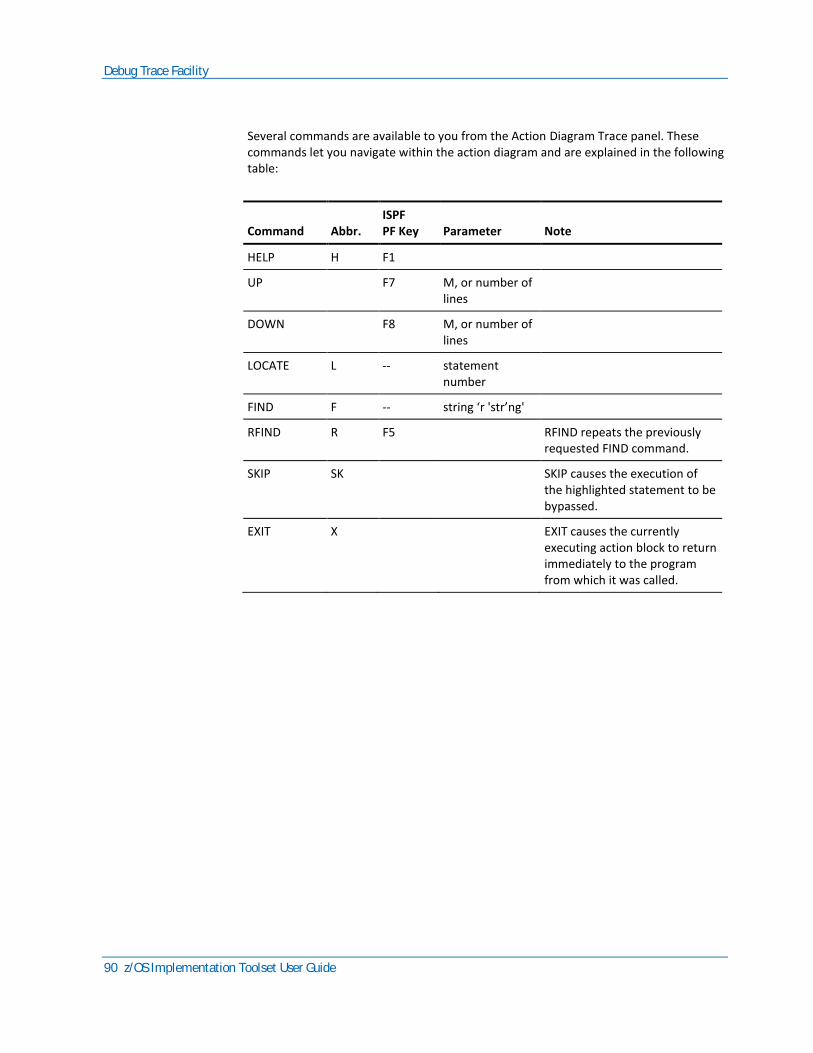
Debug Trace Facility
90 z/OS Implementation Toolset User Guide
Several commands are available to you from the Action Diagram Trace panel. These commands let you navigate within the action diagram and are explained in the following table:
Command
Abbr.
ISPF PF Key
Parameter
Note
HELP H F1
UP F7 M, or number of lines
DOWN F8 M, or number of lines
LOCATE L -- statement number
FIND F -- string ‘r 'str’ng'
RFIND R F5 RFIND repeats the previously requested FIND command.
SKIP SK SKIP causes the execution of the highlighted statement to be bypassed.
EXIT X EXIT causes the currently executing action block to return immediately to the program from which it was called.

Debug Trace Facility
Chapter 8: Testing Applications 91
Command
Abbr.
ISPF PF Key
Parameter
Note
TRACE T -- ON or OFF <UNTIL <GT/GE> stmt no>
TRACE lets you turn the action diagram trace on and off. If TRACE is OFF, the action diagram trace panel for this action diagram is not displayed. To resume the action diagram display, you must specify TRACE ON from an Action Block Call Trace Panel.
You can also request the trace be turned off until you reach a specific statement in the action diagram using the Trace Off Until Statement_number command. For example, to turn the trace off until you reach statement number 12, you would enter: TRACE OFF UNTIL 12.
To turn trace off until you reach at least statement number 15, you could enter: T OFF U GE 15. This feature is useful when you want to turn trace off (perhaps during a READ EACH) but you are not certain that statement 15 will be executed. Tracing will resume on the next statement number that is 15 or greater.
The commands in the following table can be used to control the appearance of the panel:
Command
Abbr.
ISPF PF Key
Parameter
Note
HILIGHT HI -- REVERSE, BLINK, NORMAL, UNDERLINE
The statement about to be executed is highlighted (blinking, reverse video, underlined, normal) on the panel. The default is reverse video.

Debug Trace Facility
92 z/OS Implementation Toolset User Guide
Command
Abbr.
ISPF PF Key
Parameter
Note
COLOR C -- RED, BLUE, GREEN, WHITE, TURQ, PINK, YELLOW
COLOR controls the color of the highlighted statement.
COLOR TEXT C TEXT -- RED, BLUE, GREEN, WHITE, TURQ, PINK, YELLOW
COLOR TEXT controls the color of all statements other than the highlighted statement.
Access to Other Debug Panels
The Action Diagram Trace panel also includes commands that allow you to access the other debug panels:
■ DISPLAY CALL—Displays the Action Block Call Trace panel.
■ DISPLAY vvvv—Displays the requested Action Diagram View Display panel (vvvv = IMPORT, EXPORT, LOCAL, or ENTITY).
■ DISPLAY SYSTEM—Displays the Action Diagram System View Display panel.
To return to the Action Diagram Trace panel from any of these three panels, press Enter.
Display/Modify Views
The Action Diagram View Display allows you to see the current import, export, local, or entity action views for an action diagram. The display shows the detailed information about the view and its predicates (attributes), including the current predicate values. The display also provides commands that let you expand repeating group views and modify predicate values.
The display is accessed from the Action Diagram Trace panel, using the DISPLAY vvvv command (vvvv = IMPORT, EXPORT, LOCAL, or ENTITY).

Debug Trace Facility
Chapter 8: Testing Applications 93
The following illustration shows a sample EXPORT view display.
PSCUSTOM Action Diagram EXPORT View Display
PSCUSTOM Action Diagram EXPORT View Display COMMAND ===> SCROLL ===> HALF S 1…+….10….+….20….+….30. VIEW work ief-supplied T 002 LEVEL GROUP GROUP_BANK_INFORMATION MAX=0003 CURR=0000 • VIEW output control_account • T 015 ACCOUNT NUMBER = 100 • N 006 CORPORATE_ID = +000000 • T 026 COMPANY_NAME = • T 020 STREET_ADDRESS = • T 018 CITY = • T 002 STATE = • T 009 ZIP CODE = • T 002 OPERATONS_SEGMENT_CODE = • T 005 D_B_ RATING = • T 020 REPRESENTATIVE = • T 008 SALES_REGION = •Sel codes E:Expand Repeating Group Views M:Modify data value
For entity views that are not a part of a group, the Action Diagram View Display panel displays the name of the view followed by its predicates and predicate values. The format of the display information is shown in the following illustration.
For non-repeating group views, the panel displays a line identifying the group. This is immediately followed by the entity views within the group and the predicates and predicate values for each entity view.

Debug Trace Facility
94 z/OS Implementation Toolset User Guide
For repeating group views, however, the panel displays a single line that gives the name of the group and its maximum and current cardinality. To see the views within the group, you must expand the repeating group view. You cannot expand a repeating group whose current cardinality is zero. The message Repeating Group is Empty appears at the top right of the panel. You cannot expand a non-repeating group.
To expand a repeating group, type E next to the group and press Enter. The repeating group is expanded to show the entity views defined within the group.
Expanding a nested repeating group view shows the entity views and the name of the next repeating group. Nested repeating group views allow you to expand the repeating group until you reach the inmost nested group. (Continue typing E next to the label GROUP and pressing Enter until you reach the inmost level.)
To expand an entity view within a repeating group, type E next to the entity view and press Enter. The repeating predicates of the entity view are displayed with an index identifying the predicate occurrence number and the predicate value. When you expand a repeating group that has only one entity view, the repeating predicates are immediately displayed.
The current value for each predicate (attribute) is displayed on the panel. You can change any predicate value. To modify a predicate value, type M next to the predicate to be modified, use the Tab key to position the cursor to the predicate value and enter the new value. When you exit the panel, the new value is accepted. Processing continues using the new value.
Modifying a predicate value that exceeds the screen size is a multistep process:
1. Modify the predicate value displayed on the panel.
2. Press F11 to scroll to the right. The remainder of the predicate value is displayed.
3. Modify the remainder.
Several commands are available to help you navigate within the panel. These commands are identified in the following table:
Command
Abbr.
ISPF PF Key
Parameter
Note
HELP F1
UP F7 M, or number of lines
DOWN F8 M, or number of lines
FIND F -- string ‘r 'str’ng'

Debug Trace Facility
Chapter 8: Testing Applications 95
Command
Abbr.
ISPF PF Key
Parameter
Note
RFIND R F5 RFIND repeats the previously requested FIND command.
RIGHT nnn -- F11 number of characters
RIGHT is used to view the predicate values that exceed 32 characters. Pressing RIGHT causes the predicate value portion of the panel to scroll to the right. The left side of the panel does not change. If you do not specify the number of characters to scroll, a default value of 10 is used.
LEFT nnn -- F10 number of characters
LEFT is used to view the predicate values that exceed 32 characters. Pressing LEFT causes the right side of the panel scrolls to the left. The left side does not change. If you do not specify the number of characters to scroll, a default value of 10 is used.
Display System Variables
The Action Diagram System View Display panel allows you to see the current runtime values of the system variables. This panel is accessed with the DISPLAY SYSTEM command. The variables are the Special Attributes available to you during Business System Design. The variables are generated and maintained by the CA Gen and can be used by your application system. This panel displays the current values of the system variables, whether or not you have chosen to use them in your application.
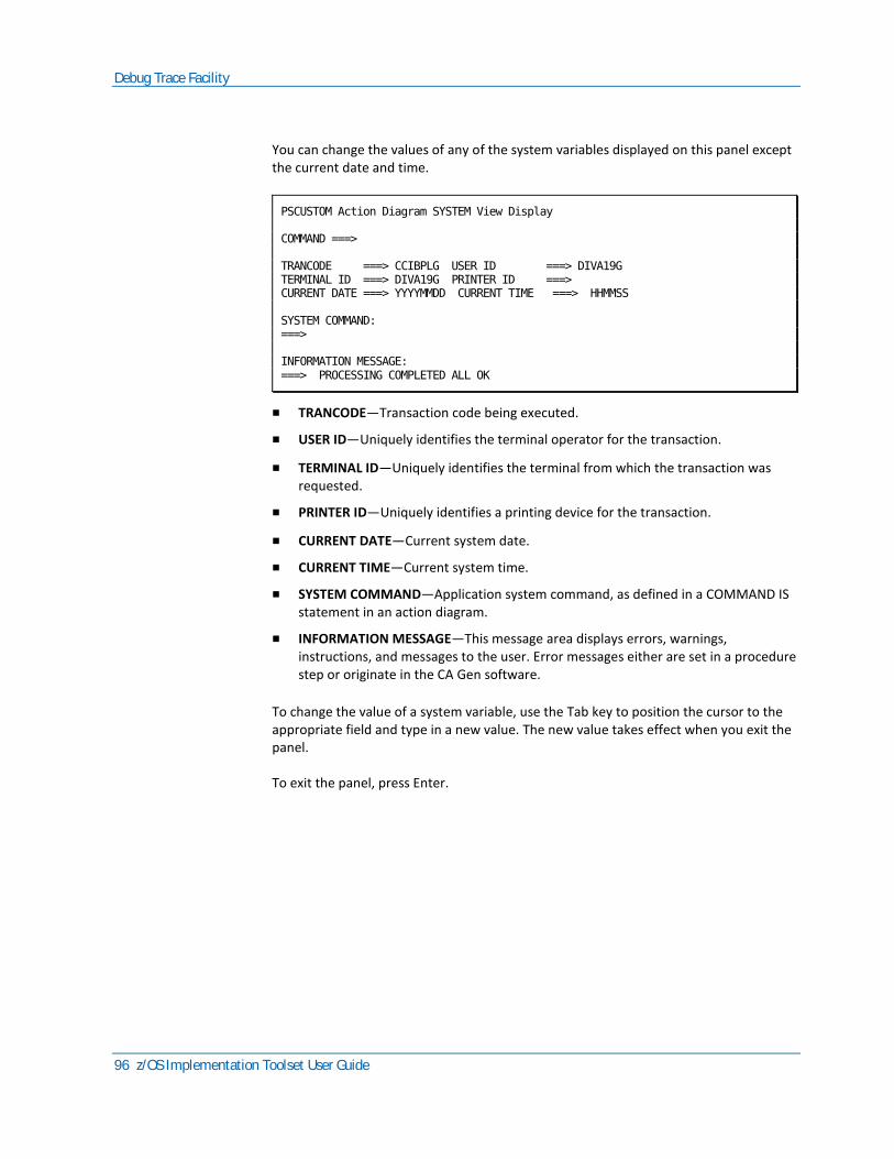
Debug Trace Facility
96 z/OS Implementation Toolset User Guide
You can change the values of any of the system variables displayed on this panel except the current date and time.
PSCUSTOM Action Diagram SYSTEM View Display COMMAND ===> TRANCODE ===> CCIBPLG USER ID ===> DIVA19G TERMINAL ID ===> DIVA19G PRINTER ID ===> CURRENT DATE ===> YYYYMMDD CURRENT TIME ===> HHMMSS SYSTEM COMMAND: ===> INFORMATION MESSAGE: ===> PROCESSING COMPLETED ALL OK
■ TRANCODE—Transaction code being executed.
■ USER ID—Uniquely identifies the terminal operator for the transaction.
■ TERMINAL ID—Uniquely identifies the terminal from which the transaction was requested.
■ PRINTER ID—Uniquely identifies a printing device for the transaction.
■ CURRENT DATE—Current system date.
■ CURRENT TIME—Current system time.
■ SYSTEM COMMAND—Application system command, as defined in a COMMAND IS statement in an action diagram.
■ INFORMATION MESSAGE—This message area displays errors, warnings, instructions, and messages to the user. Error messages either are set in a procedure step or originate in the CA Gen software.
To change the value of a system variable, use the Tab key to position the cursor to the appropriate field and type in a new value. The new value takes effect when you exit the panel.
To exit the panel, press Enter.
Debug Trace Facility
Chapter 8: Testing Applications 97
Making Changes to an Application
After testing an application, you may find that you need to make changes to it. Always make the necessary changes to the related action diagrams, views, and screens, regenerate the source, and reinstall the application.
Important! If you change a diagram that is the source of information for a generated load module, you must regenerate one or more of the load module components. The type and scope of the change determine which load module components need to be regenerated. Occasionally, you may need to regenerate the complete load module. More often, changes that affect specific components require that you regenerate those components.
Common Testing Errors
The following is a list of some of the common errors made during testing. The list is not intended to cover all possible common errors under all possible conditions.
■ All load module components you need for your test must be generated and installed. If you are testing the flow between two procedure steps, be sure that both procedure steps have been installed.
■ If you attempt to access a load module that has not been generated, the test fails. If the attempt is made from within the Application Test Facility, the error message is:
CSV0031 REQUESTED MODULE module_name NOT FOUND
■ Press End (as defined in the testing environment for your application) to return to a clear screen.
■ To test any part of a multistep procedure, you must always generate the first procedure step as well as the procedure steps you intend to test. This is because the first procedure step provides the access to all other procedure steps in the procedure.
■ You can only use the Debug Trace Facility with those components for which you generated debug support. You can, however, test components without using the Debug Trace Facility.
■ All load module components must be generated before the load module can be installed.
■ If any component has not been generated and is not Dynamically called, the install will fail. The link-edit step will have unresolved references.
■ A load module must be installed before it can be tested. Ensure that it is installed using the correct installation parameters. For the Application Test Facility, be sure to specify IEFAE as your target environment, or on the Host, select the Target TSO test facility option. For CICS, do not select this option; specify CICS as your target environment.

Debug Trace Facility
98 z/OS Implementation Toolset User Guide
If you are testing a load module within the Application Test Facility that uses an external action block that contains IMS or CICS environment calls or DL/I calls, be sure to comment out the IMS, CICS, or DL/I calls within the external action block or the external action block itself. Otherwise, the test abends with a System 0C1 or 0C4 Abend.
Chapter 9: Background Utility 99
Chapter 9: Background Utility
This chapter shows how to use the Background Utility process. During the process, the Background Utility:
■ Provides opportunity to enter Job Card information to be used in building the JCL
■ Builds a JCL member you can modify to invoke the background utility
Provide Job Card Information
This portion of the Background Utility process allows you to provide your own job card to be included in the JCL built by the process. Incomplete job card information does not stop the process from continuing to build the JCL member to be used in submitting the batch job. This job card information is saved and redisplayed the next time you invoke the Background Utility.
To continue with the process:
1. Provide the job card information.
2. Press Enter.
Build JCL Member
This section discusses the minimum required changes for the Background Utility to process completely.
Perform the following steps if the job card information is incomplete.
Provide the Name of the Target Definition
Provide the name of the target definition that has the properties against which you want to process. For example, you want to build executables for IEFAE/COBOL/BYPASS. There is a DD name TARGET provided in the JCL that must not be modified (//TARGET cannot be changed to //TAR). However, you must either provide a data set name that contains the target definition name or indicate the target name in-stream just below the TARGET DD name. The DCB information for the REMOTES data set is FB (fixed block) and LRECL (logical record length) 80.
Note: The Target Definition used for the Background Utility must be already created. For more information, see the chapter "Defining the Target Configuration."

Build JCL Member
100 z/OS Implementation Toolset User Guide
Example A: Target Name Provided as In-stream Data
The following is an example where the target name is provided as in-stream data:
//TARGET DD *
MYTARGET NAME
/*
Example B: Target Name Provided as Sequential Data Set
The following is an example where the target name is provided as sequential data set:
//TARGET DD DSN=SEQ.DATA.SET,DISP=SHR
Where SEQ.DATA.SET is some sequential data set that contains the name of your target definition.
BROWSE SEQ.DATA.SET Command ===> ********************* Top of Data ******* MYTARGET NAME ******************** Bottom of Data *****
Example C: Target Name Provided as Member of PDS
The following is an example where the target name is provided as member of PDS:
//TARGET DD DSN=PDSDATA.SET(TARMEM),DISP=SHR
Where PDSDATA.SET is some PDS and TARMEM contains the name of your target definition.
BROWSE PDSDATA.SET(TARMEM) Command ===> ********************** Top of Data ****** EXAMPLE TARGET DEFNAME ******************** Bottom of Data *****
Provide the List of Remote Files
Provide the list of remote files you want to process in batch. However, do not modify DD name REMOTES, provided in the JCL. The input must be in a specific format, and if it contains errors processing of that remote stops and processing continues with the next remote in the list.

Build JCL Member
Chapter 9: Background Utility 101
Format of Remote File
Commas separate the remote input stream and the length indicated in (). The values for the 1-byte options are Y or N. The Member Name field may be skipped if the data set is a sequential file. In that case, you would specify 2 commas ',,' together indicating no member name.
Register Selected, (1)
Split Selected, (1)
Compose Selected, (1)
Execute Selected, (1)
Install Selected, (1)
Delete RMT Flag, (1)
Member Name, (8)
DSN or RMT Name, (44)
You have flexibility on how you indicate the remotes:
■ Indicate the list in-stream.
■ Indicate data sets that contain the information needed.
The data sets can be either sequential or partitioned. You can specify multiple sequential data sets. If the data set is partitioned, the list of remotes can be in a single or multiple members of the PDS. The DCB information for the REMOTES data set is FB (fixed block) and LRECL (logical record length) 80.
Example D: Sequential Remotes Provided as In-stream Data
The following is an example where sequential remotes are provided as in-stream data:
//REMOTES DD *
Y,Y,Y,Y,N,N,,'SEQ.DATA.SET.CASCADE.RMT'
Y,Y,Y,Y,Y,N,,'SEQ.DATA.SET.NAME1.RMT'
Y,Y,Y,Y,Y,N,,'SEQ.DATA.SET.NAME2.RMT'
/*
Example E: PDS Remotes Provided as In-stream Data
The following is an example where PDS remotes are provided as in-stream data:
//REMOTES DD *
Y,Y,Y,Y,N,N,CASCADE,'PDS.DATA.SET'
Y,Y,Y,Y,Y,N,RMTNAME1,'PDS.DATA.SET'
Y,Y,Y,Y,Y,N,RMTNAME2,'PDS.DATA.SET'
/*

Build JCL Member
102 z/OS Implementation Toolset User Guide
Example F: Sequential Data Set Containing List of Remotes
The following is an example of sequential data set containing list of remotes:
//REMOTES DD DSN=SEQ.DATA.SET,DISP=SHR
Contents of SEQ.DATA.SET:
BROWSE SEQ.DATA.SET Command ===> ******************** Top of Data ******** Y,Y,Y,Y,N,N,,'SEQ.DATA.SET.CASCADE.RMT' Y,Y,Y,Y,Y,N,,'SEQ.DATA.SET.NAME1.RMT' Y,Y,Y,Y,Y,N,,'SEQ.DATA.SET.NAME2.RMT' Y,Y,Y,Y,Y,N,RMTNAME3,'PDS.DATA.SET' Y,Y,Y,Y,Y,N,RMTNAME4,'PDS.DATA.SET' ******************* Bottom of Data ******
Example G: PDS Members Containing List of Remotes
The following is an example of PDS members containing list of remotes:
//REMOTES DD DSN=SEQ.DATA.SET,DISP=SHR
//REMOTES DD DSN=RMTLIST.DATA(RMTMEM),DISP=SHR
Contents of RMTLIST.DATA(RMTMEM):
BROWSE RMTLIST.DATA(RMTMEM) Command ===> ******************** Top of Data ******** Y,Y,Y,Y,N,N,,'SEQ.DATA.SET.CASCADE.RMT' Y,Y,Y,Y,Y,N,,'SEQ.DATA.SET.NAME1.RMT' Y,Y,Y,Y,Y,N,,'SEQ.DATA.SET.NAME2.RMT' Y,Y,Y,Y,Y,N,RMTNAME3,'PDS.DATA.SET' Y,Y,Y,Y,Y,N,RMTNAME4,'PDS.DATA.SET' ******************* Bottom of Data ******

Build JCL Member
Chapter 9: Background Utility 103
Example H: Multiple PDS Members Containing List of Remotes
The following is an example of multiple PDS members containing list of remotes:
//REMOTES DD DSN=RMTLIST.DATA(RMTMEM1),DISP=SHR
//DD DSN=RMTLIST.DATA(RMTMEM2),DISP=SHR
Contents of RMTLIST.DATA(RMTMEM1):
BROWSE RMTLIST.DATA(RMTMEM1) Command ===> ******************** Top of Data ******** Y,Y,Y,Y,N,N,,'SEQ.DATA.SET.CASCADE.RMT' Y,Y,Y,Y,Y,N,,'SEQ.DATA.SET.NAME1.RMT' Y,Y,Y,Y,Y,N,,'SEQ.DATA.SET.NAME2.RMT' ******************* Bottom of Data ******
Contents of RMTLIST.DATA(RMTMEM2):
BROWSE RMTLIST.DATA(RMTMEM2) Command ===> ******************** Top of Data ******** Y,Y,Y,Y,Y,N,RMTNAME3,'PDS.DATA.SET' Y,Y,Y,Y,Y,N,RMTNAME4,'PDS.DATA.SET' ******************* Bottom of Data ******
Just like in the foreground process, you may choose to perform certain actions against the remote in multiple passes (indicate to do Register, Split, and Compose for Remote A on one line and indicate to do Execute and Install on another). This allows common action blocks to be split out from the various remotes and compiled once.
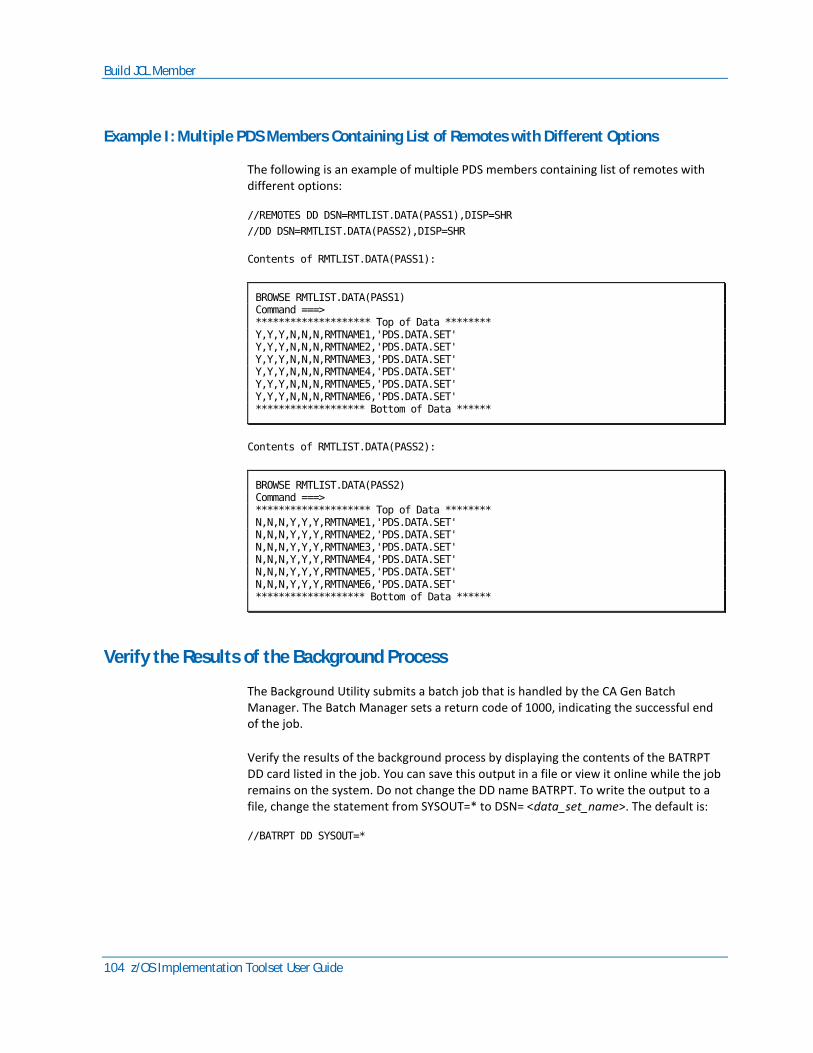
Build JCL Member
104 z/OS Implementation Toolset User Guide
Example I: Multiple PDS Members Containing List of Remotes with Different Options
The following is an example of multiple PDS members containing list of remotes with different options:
//REMOTES DD DSN=RMTLIST.DATA(PASS1),DISP=SHR
//DD DSN=RMTLIST.DATA(PASS2),DISP=SHR
Contents of RMTLIST.DATA(PASS1):
BROWSE RMTLIST.DATA(PASS1) Command ===> ******************** Top of Data ******** Y,Y,Y,N,N,N,RMTNAME1,'PDS.DATA.SET' Y,Y,Y,N,N,N,RMTNAME2,'PDS.DATA.SET' Y,Y,Y,N,N,N,RMTNAME3,'PDS.DATA.SET' Y,Y,Y,N,N,N,RMTNAME4,'PDS.DATA.SET' Y,Y,Y,N,N,N,RMTNAME5,'PDS.DATA.SET' Y,Y,Y,N,N,N,RMTNAME6,'PDS.DATA.SET' ******************* Bottom of Data ******
Contents of RMTLIST.DATA(PASS2):
BROWSE RMTLIST.DATA(PASS2) Command ===> ******************** Top of Data ******** N,N,N,Y,Y,Y,RMTNAME1,'PDS.DATA.SET' N,N,N,Y,Y,Y,RMTNAME2,'PDS.DATA.SET' N,N,N,Y,Y,Y,RMTNAME3,'PDS.DATA.SET' N,N,N,Y,Y,Y,RMTNAME4,'PDS.DATA.SET' N,N,N,Y,Y,Y,RMTNAME5,'PDS.DATA.SET' N,N,N,Y,Y,Y,RMTNAME6,'PDS.DATA.SET' ******************* Bottom of Data ******
Verify the Results of the Background Process
The Background Utility submits a batch job that is handled by the CA Gen Batch Manager. The Batch Manager sets a return code of 1000, indicating the successful end of the job.
Verify the results of the background process by displaying the contents of the BATRPT DD card listed in the job. You can save this output in a file or view it online while the job remains on the system. Do not change the DD name BATRPT. To write the output to a file, change the statement from SYSOUT=* to DSN= <data_set_name>. The default is:
//BATRPT DD SYSOUT=*
Build JCL Member
Chapter 9: Background Utility 105
Example J
The following is an example to verify the results of the background process:
//BATRPT DD DSN=BATCH.OUTPUT,DISP=(NEW,CATLG,DELETE),
// DCB=(RECFM=FBA,BLKSIZE=10640,LRECL=133)
Add any other JCL parameters necessary at your site to complete the data set definition.
Submit
Submit the job once you have completely modified the JCL member. Possible processing errors you might encounter are similar to those in foreground processing. For example, external action blocks must be available to include in the link-edit portion and target libraries may run out of space and need to be corrected.
Execution Parameters Available
The Execute step for the IT performs the COMPILE, LINK, and BIND actions by default for both the foreground and background processing. The REXX CLIST built as a result of the Compose step may be executed manually. The composed CLIST, when executed manually, has other parameters available to change the action of the Execute step.
Following is a list of the available parameters:
■ COMPILE—Compiles all load module members which "need" to be compiled, that is, those modules which have been split but have never been compiled.
■ COMPILE(X)—Compiles X, where X is the name of a load module member.
■ COMPALL—Compiles all load module members.
■ PACKAGE(X)—Binds package X, where X is the name of a load module member that is included in a collection and has SQL.
■ PACKALL—Package binds all load module members with SQL. Normally needed only if no compiles are to be done.
■ LINK—Links the load module containing the dialog manager and all load module members (action blocks, screens, and procedure steps) that are dynamically loaded.
■ LINK(X)—Links X, where X is the name of the dialog manager load module or a dynamically loaded load module member.
■ BIND—Binds application plan.
■ LINEMODE—Displays status messages in line mode.
■ DEBUG—Traces command execution using trace R REXX statement.
If this CLIST is in a library NOT in your ISPF SYSPROC concatenation, it may be invoked from the TSO command processor screen (ISPF 6).

Build JCL Member
106 z/OS Implementation Toolset User Guide
Example K: Invoking CLIST from TSO Command Processor
The following is an example of invoking CLIST from TSO command processor:
EXEC 'AAAC.CLIB(XYZ)' 'COMPALL LINEMODE'
If this CLIST is in a library in your ISPF SYSPROC concatenation, it may be invoked from any TSO command line.
Example L: Invoking CLIST from TSO Command Line
The following is an example of invoking CLIST from TSO command line:
TSO XYZ COMPALL LINEMODE
This CLIST may be executed in the background using the JCL created for you with the Background Utility. You specify the modified ISPSTART statement within the SYSTSIN input stream.
Example M: Invoking CLIST from JCL
The following is an example of invoking CLIST from JCL:
//SYSTSIN DD *
PROFILE PREFIX(TSOID) WTPMSG
ISPSTART CMD(EXEC 'AAAC.CLIB(GENLM1)' 'COMPILE LINEMODE')
ISPSTART CMD(EXEC 'AAAC.CLIB(GENLM2)' 'COMPILE LINK PACKALL')
ISPSTART CMD(EXEC 'AAAC.CLIB(GENLM3)' 'COMPILE(PSTEPA) LINEMODE')
/*
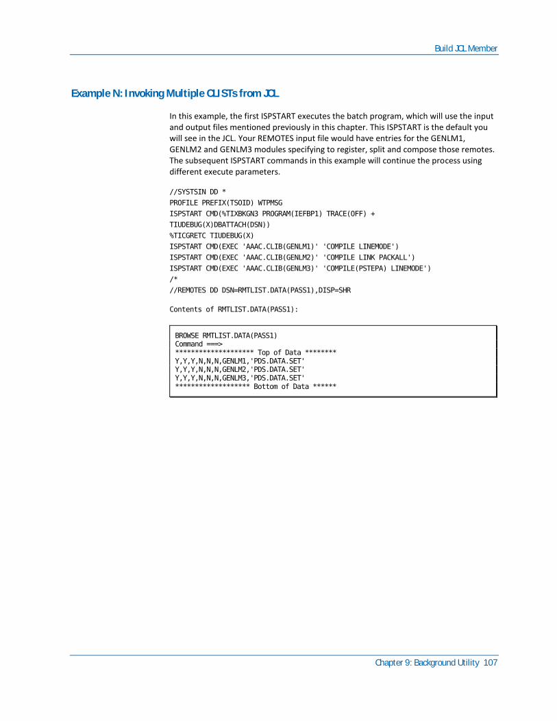
Build JCL Member
Chapter 9: Background Utility 107
Example N: Invoking Multiple CLISTs from JCL
In this example, the first ISPSTART executes the batch program, which will use the input and output files mentioned previously in this chapter. This ISPSTART is the default you will see in the JCL. Your REMOTES input file would have entries for the GENLM1, GENLM2 and GENLM3 modules specifying to register, split and compose those remotes. The subsequent ISPSTART commands in this example will continue the process using different execute parameters.
//SYSTSIN DD *
PROFILE PREFIX(TSOID) WTPMSG
ISPSTART CMD(%TIXBKGN3 PROGRAM(IEFBP1) TRACE(OFF) +
TIUDEBUG(X)DBATTACH(DSN))
%TICGRETC TIUDEBUG(X)
ISPSTART CMD(EXEC 'AAAC.CLIB(GENLM1)' 'COMPILE LINEMODE')
ISPSTART CMD(EXEC 'AAAC.CLIB(GENLM2)' 'COMPILE LINK PACKALL')
ISPSTART CMD(EXEC 'AAAC.CLIB(GENLM3)' 'COMPILE(PSTEPA) LINEMODE')
/*
//REMOTES DD DSN=RMTLIST.DATA(PASS1),DISP=SHR
Contents of RMTLIST.DATA(PASS1):
BROWSE RMTLIST.DATA(PASS1) Command ===> ******************** Top of Data ******** Y,Y,Y,N,N,N,GENLM1,'PDS.DATA.SET' Y,Y,Y,N,N,N,GENLM2,'PDS.DATA.SET' Y,Y,Y,N,N,N,GENLM3,'PDS.DATA.SET' ******************* Bottom of Data ******

Chapter 10: Testing, Production, and Maintenance 109
Chapter 10: Testing, Production, and Maintenance
This chapter contains an overview of the activities that occur after an application is installed in your target environment. Many of the procedures discussed in this document are performed outside the IT. Since the process varies according to the configuration of your target system, specific steps are omitted. However, the pre- and post-conditions required for the CA Gen application to run are defined.
Application Testing
Before you can test a complete application, you must use the Installation Tool to install the application database, RI trigger logic, and all load modules that are part of the application. The Application Test Facility, in conjunction with the Application Execution Facility (IEFAE), is used to test a CA Gen generated application before the application is moved to the production environment.
If you want to make changes to the application, you must change the CA Gen model used to generate the application, not the generated code. This applies whether the change is made to correct a problem or enhance the application.
After changing the model, regenerate the changed portion of your application on your code generation platform.
If your changes do not update the load module definition, you can elect to regenerate only the necessary load module components instead of the complete load module. Then move the regenerated components to your target system, overlay the old versions of the components with the new ones, and reinstall the load module using the Install Load Module menu option in the Installation Tool. This saves the time and resources required to register and split a remote file whose definition has not changed.
If you changed the Load Module definition or changed most of the components in a Load Module, you can elect to generate an entirely new remote file. Move the resulting remote file to your target system. You can then register the new remote file, build, and implement the application again.
Making changes to the code on your target system is not recommended under any circumstances. This practice results in a model different from the generated code, and the process of making further changes becomes unmanageable. If you change the generated code, many of the benefits of the Information Engineering process are lost.

Application Production
110 z/OS Implementation Toolset User Guide
Application Production
When the application is ready for production, move it into the proper environment and introduce it into production. These tasks can be performed differently by each organization using the IT. Some elements are common to all installations.
The dialog manager of any CA Gen generated application can customize system functions, such as retrieving a user ID or handling errors, for access. You can customize these elements (user exits) for specific target systems. User exits are source language routines. Make sure the user exits DLLs are in a library that is accessible to the dialog manager during the execution of CA Gen generated application.
For instructions appropriate to the configuration of your target system refer to the chapter "Define the Target Configuration."
Production in the IEFAE Environment
To use the IEFAE environment, the components necessary for CA Gen generated application to run in production are:
■ The application itself
■ The database used by the application
■ The relevant runtime DLLs
The runtime DLLs required by IEFAE are TSOAE, TIRTSOCS, TIRTSODV, TIRTSOST and TIRTSXSU. The CA Gen runtime DLLs required for a CA Gen generated application to run are TIRARUNT, TIRORUNT, TIRMTQBZ, TIRTERAZ, TIRPRFQZ, TIRRTLDT, TIRDEVTZ, TIRIRTRZ, TIRIURTZ and TIRTSYSZ. In addition, the DLLs required for generated Block Mode Enhanced Map applications are TIRCGSPZ, TIRCHPZ, TIRCHPRZ, TIRCIIMZ, TIRCO2PZ, TIRCO2SZ, TIRCPINZ, TIRCPUIZ, TIRCVINZ, and TIRIEXZ. The TIRIEXSZ DLL is required for generated Block Mode Standard Map applications.
The IEFAE serves as an operating environment that handles many aspects of communication between the operating system and the CA Gen generated application.
Batch
To execute CA Gen Batch applications under IEFAE the following DLLs are required for IEFAE: TSOAE, TIRTSOCS, TIRTSODV, TIRTSOST, and TIRTSXSU. The CA Gen runtime modules required for a CA Gen generated application to run in Batch are TIRBRUNT, TIRARUNT, TIRORUNT, TIRMTQBZ, TIRTERBZ, TIRBRTRZ, TIRBURTZ, TIRRTLDT, and TIRRETCZ.
To execute a CA Gen Batch application under JES the following DLLs are required: TIRBRUNB, TIRARUNI, TIRORUNI, TIRMTQBZ, TIRBRTRZ, TIRBURTZ, and TIRRETCZ.

Application Maintenance
Chapter 10: Testing, Production, and Maintenance 111
Production in the CICS Environment
To use the CICS environment, you must define all program names and trancodes to the CICS program and transaction tables. For sample table definitions to use as templates for CICS applications see z/OS Installation Guide. Contact your CICS system administrator for help in defining the programs and trancodes.
In addition, you need to make the various CA Gen Runtime modules available in the CICS region being targeted. For more information about which Runtime modules are required, see z/OS Installation Guide.
Production in the IMS Environment
To use the IMS environment, you must define all psbs, program names and trancodes to the IMS Systems. For sample table definitions to use as templates for IMS applications see z/OS Installation Guide. Contact your IMS system administrator for help in defining the psbs, programs and trancodes.
In addition, you need to make the various CA Gen Runtime modules available in the IMS system being targeted. For more information about which Runtime modules are required, see z/OS Installation Guide.
Application Maintenance
All maintenance of a CA Gen generated application must be performed on the model from which the application is generated. Until changes are necessary, store the model in the Host Encyclopedia or the CSE with appropriate backup copies stored separately for recovery.
Model management is one of the most demanding tasks in CA Gen system development. The Host Encyclopedia or the Client Server Encyclopedia are ideal control points for model and subset management. The Host Encyclopedia Guide and Client Server Encyclopedia Guide are excellent references on the subject of general model management. The Host Encyclopedia Subsetting Guide, Client Server Encyclopedia Subsetting Guide, Host Encyclopedia Version Control Guide, and the Client Server Encyclopedia Version Control Guide provide advanced references on the functions of migration and subsetting.

Application Migration
112 z/OS Implementation Toolset User Guide
Application Migration
There are different application migration requirements depending on the CA Gen release that the application is migrating from as well as the type of linkage the application uses to invoke the various components of that application.
To aid migration from releases of AllFusion Gen before release 7, the Compatibility setting for the Dynamically Link Packaging property can be used.
Its purpose is to:
■ Enable CA Gen 8.5 applications (which are built as DLLs) to call components built as non-DLL load modules.
■ Optionally, build components that cannot be DLLs as non-DLLs and have them use the same z/OS runtime as CA Gen 8.5 DLL applications.
Note: Since the Compatibility feature was not available in AllFusion Gen 7 or 7.5, any component previously migrated to these releases became DLLs. Thus migration information from these releases to CA Gen 8.5 does not mention Compatibility.
For more information about Compatibility and migrating to CA Gen 8.5, see the Release Notes of this release as well as the previous releases.
Migrating from CA Gen 8
The CA Gen 8.5 z/OS Runtime DLLs must be deployed to the target execution environment and supersede those Runtimes provided with CA Gen 8. CA Gen 8.5 generated applications and runtime DLLs must reside in PDSE libraries.
Migrating from Release 7.6
All components of AllFusion Gen 7.6 applications were installed to resolve addressability to the runtimes residing in DLLs. In addition all Gen 7.6 applications are themselves DLLs so there are no activities required to migrate an application from AllFusion Gen 7.6 to CA Gen 8.5.
The CA Gen 8.5 z/OS Runtime DLLs must be deployed to the target execution environment and supersede those Runtimes provided with AllFusion Gen 7.6. CA Gen 8.5 generated applications and runtime DLLs must reside in PDSE libraries.

Application Migration
Chapter 10: Testing, Production, and Maintenance 113
Migrating from Allfusion Gen 7.5
All components of AllFusion Gen 7.5 applications were installed to resolve addressability to the runtimes residing in DLLs. In addition all Gen 7.5 applications are themselves DLLs so there are no activities required to migrate an application from AllFusion Gen 7.5 to CA Gen 8.5.
The CA Gen 8.5 z/OS Runtime DLLs must be deployed to the target execution environment and supersede those Runtimes provided with AllFusion Gen 7.5. CA Gen 8.5 generated applications and runtime DLLs must reside in PDSE libraries.
Migrating from Release 7
Compiler options changed in AllFusion Gen 7 to enable the creation and use of DLLs. A small portion of the runtimes were built as DLLs in AllFusion Gen 7 with most of the remainder becoming DLLs in AllFusion Gen 7.6. The CA Gen 8.5 applications need to be compiled using options that enable DLL support to use the runtime DLLs.
When migrating from AllFusion Gen 7 to CA Gen 8.5, evaluate how the AllFusion Gen 7 application was built and do one of the following:
1. If all the components of an application were compiled in AllFusion Gen 7, then reinstall all the existing code to re-link the application. The re-link step resolves the addressability of the runtimes located in the DLLs. Ensure that runtimes from previous releases are not inadvertently picked up from the SYSLIB concatenation through auto-call. The CA Gen 8.5 load library contains all the required runtimes. Load libraries from previous releases must not be included in the SYSLIB concatenation.
2. If only certain components of an application were compiled in AllFusion Gen 7, recompile all the components being migrated that were not previously compiled at the AllFusion Gen 7 level and re-link all components. A recompile is required to ensure that the generated components are built with DLL support and a re-link is required to resolve the addressability of the runtimes located in the DLLs. The CA Gen 8.5 load library contains all the required runtimes. Load libraries from previous releases must not be included in the SYSLIB concatenation.
Important! Failure to recompile these migrated components will cause unpredictable results.
When using the Implementation Toolset for z/OS to re-link, but not to recompile an application, process the existing IP by selecting only the Register, Execute, and Install options of the Detailed IP Action Menu. Do not select the Split option. Ensure that CA Gen 8.5 Scripts and Target are used. The CA Gen 8.5 Target locations (datasets) used must be same as those used previously to build the application being migrated. CA Gen 8.5 generated applications and runtime DLLs must reside in PDSE libraries.
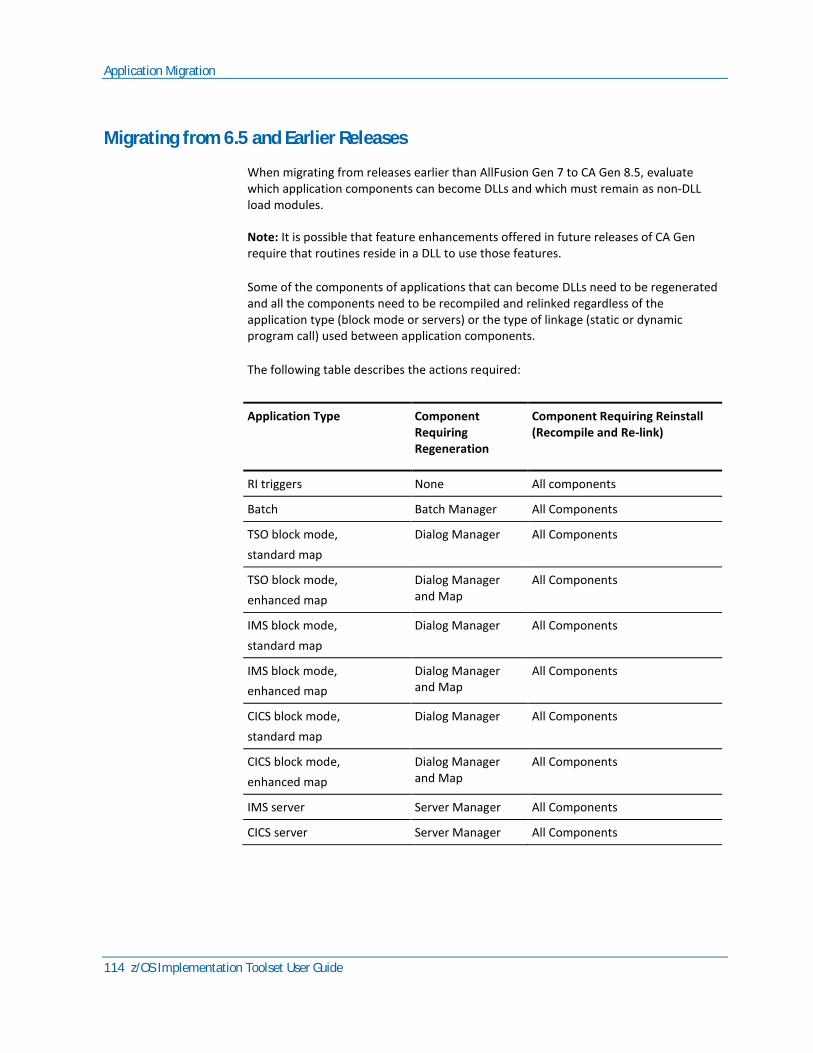
Application Migration
114 z/OS Implementation Toolset User Guide
Migrating from 6.5 and Earlier Releases
When migrating from releases earlier than AllFusion Gen 7 to CA Gen 8.5, evaluate which application components can become DLLs and which must remain as non-DLL load modules.
Note: It is possible that feature enhancements offered in future releases of CA Gen require that routines reside in a DLL to use those features.
Some of the components of applications that can become DLLs need to be regenerated and all the components need to be recompiled and relinked regardless of the application type (block mode or servers) or the type of linkage (static or dynamic program call) used between application components.
The following table describes the actions required:
Application Type Component Requiring Regeneration
Component Requiring Reinstall (Recompile and Re-link)
RI triggers None All components
Batch Batch Manager All Components
TSO block mode,
standard map
Dialog Manager All Components
TSO block mode,
enhanced map
Dialog Manager and Map
All Components
IMS block mode,
standard map
Dialog Manager All Components
IMS block mode,
enhanced map
Dialog Manager and Map
All Components
CICS block mode,
standard map
Dialog Manager All Components
CICS block mode,
enhanced map
Dialog Manager and Map
All Components
IMS server Server Manager All Components
CICS server Server Manager All Components
Application Migration
Chapter 10: Testing, Production, and Maintenance 115
Components that need to remain as non-DLL load modules must use the CA Gen 8.5 z/OS Dynamic Program Call Compatibility feature.
This feature allows a phased migration of applications built by releases of AllFusion Gen before release 7, that use dynamically called procedure steps, screens, or action blocks (including EABs). The Compatibility setting causes the caller of a module marked for compatibility to always be regenerated and reinstalled, to include a call to the runtime routine that handles the call to the non-DLL load module. The option Process modules marked for Compatibility determines what components are rebuilt as release 8.5 non-DLL load modules. The option Process modules marked for Compatibility can be selected to regenerate and reinstall the components or just to reinstall them. The reinstall is required to enable the non-DLL load modules to use the CA Gen 8.5 DLL runtimes.
RI triggers and action blocks that are statically called by modules marked for Compatibility must be built using the NODLL compiler option. If these RI triggers and action blocks are also used in Gen applications that are built as DLLs they need to be compiled using the DLL option. Selecting the Process modules marked for Compatibility option causes the RI triggers and any action blocks statically called by modules marked for Compatibility to be generated and precompiled once but compiled twice. Separate libraries are provided in the target environment to hold the separate NCAL modules resulting from the two compile steps.
Applications that run under TSOAE and contain modules marked for Compatibility cannot dynamically call modules built with a release before CA Gen 8.5.
Enhanced Map Block Mode applications containing screens marked for Compatibility cannot dynamically call screen managers built with a release before CA Gen 8.5.
Important! Ensure that runtimes from previous releases are not inadvertently picked up from the SYSLIB concatenation through an auto-call. The CA Gen 8.5 load library contains all the required runtimes. Load libraries from previous releases must not be included in the SYSLIB concatenation.
CA Gen 8.5 runtimes and generated code must reside in PDSE libraries. When migrating from previous releases of CA Gen using the Implementation Toolset, ensure that the Business System data sets specified for the NCAL, EXE, IMPL, RI Load Lib and, if used, the Static NCAL, Static RI NCAL or Static External Action Block libraries are allocated as PDSEs before processing the release 7.6 script.
EAB Migration
When an External Action Block has its associated Dynamically Linked Packaging property set to Yes, migrating to CA Gen 8.5 requires the EAB to be recompiled and reinstalled as a DLL. If the EAB dynamically calls other user programs, those user programs must also be built as DLLs.

Application Migration
116 z/OS Implementation Toolset User Guide
When an External Action Block has its associated Dynamically Linked Packaging property set to Compatibility, the option Process modules marked for Compatibility determines if the EAB must be rebuilt as a z/OS non-DLL load module or should remain as built by the releases of AllFusion Gen before release 7. In either case, if the EAB dynamically calls other user programs, those user programs must also be non-DLLs.
How an External Action Block that has its associated Dynamically Linked Packaging property set to NO, thus is statically linked into the calling application, is compiled depends on the type of application that calls it. When the calling application is marked for Compatibility the EAB must be built using the NODLL compiler option and be placed in a library in the Static External Action Block panel. When the calling application is not marked for Compatibility the EAB must be built using the DLL compiler option and be placed in a library in the External Action Block panel. When called by both application types, two copies of the EAB must be built and each placed in the appropriate library.
In CA Gen 8.5 if an EAB uses a CICS XCTL or CICS START API command to flow to another CICS transaction (thus not returning), that EAB must delete a TSQ before it executes the XCTl or START.
If the application executing the EAB was built by CA Gen 8.x, the TSQ is named MMCB<APPLID>#### (where #### is the packed CICS Taskid).
If the application executing the EAB was built by CA Gen 7.6 or earlier release, the TSQ name is AMCB<APPLID>####.
For more information about EABs, see the chapter "Implementing External Action Blocks."

Load Module Packaging
Chapter 10: Testing, Production, and Maintenance 117
z/OS Runtime User Exits
In CA Gen 8.5, user exits reside in the z/OS runtime DLLs. Customers migrating to CA Gen 8.5 must rebuild those user exits they have customized in prior release of Gen. The user exits are no longer linked into each generated application. All modified user exit must be rebuilt so they can be updated in their respective CA Gen 8.5 runtime DLL. JCL procedures that build the user exits and their specific DLLs are provided in the relevant CEHBSAMP datasets in members MKUEXITS, MK5EXITS (COBOL 5), MKUECTCP, and MKUEITCP respectively. The JCL to re-build the User Exits used by the C runtimes for Codepage translation reside in the member MKCRUN in the CEHBSAMP dataset. If the TIRXINFO user exit (included in MKCRUN) is modified, the resulting TIRXINFZ DLL must also be deployed.
Important! Care must be taken to ensure that the user exits used from previous releases are not inadvertently picked up from the SYSLIB concatenation through an auto-call. The CA Gen 8.5 user exits must be updated in their respective z/OS Runtime DLL.
For more information about User Exits and their associated JCL procedures, see the chapter 'Customizing and Installing User Exits', or the User Exits Guide.
Load Module Packaging
Load module packaging for target system implementation is an important consideration during the maintenance phase of the CA Gen application development life cycle. The load module definition determines the contents of each load module remote file. The control information is updated each time you change the load module packaging. Unless precautions are taken, an incorrect load module definition can overwrite a correct one on the target system once the remote file is transferred to the target system and processed.
Online load module packaging and member name assignment can be done in the encyclopedia using Host Construction. Packaging and member name information created in the encyclopedia is included when a subset is checked out. From CA Gen 8, online load module packaging and member name assignment can also be done in the Toolset using workstation construction and it will be uploaded and checked into the encyclopedia.
Cooperative load module packaging and member name assignment should be done in the Toolset using Workstation Construction. This packaging is always uploaded and checked in to the encyclopedia.
Load Module Packaging
118 z/OS Implementation Toolset User Guide
When creating a subset of the model for code generation, include all the elements necessary to regenerate a complete load module. To be sure that a subset includes all components of a load module, look at the packaging for that load module. Then, for each procedure step in the load module:
■ Scope the procedure that includes the procedure step.
■ Ask for the default (blank) expansion option of the procedure.
■ Ask for Read (R) access to each procedure (to change some part of the procedure; you must ask for Modify or Delete access).
■ Scope the database. Ask for Read access and default expansion.
Important! The load module definition determines what is included in load module remote files. If you elect to generate and install only code changes, all of the elements of the load module that can be found by CA Gen are included in the remote file. Elements of a load module packaged having an associated Dynamically Link Packaging property set to Compatibility will only be included in the remote file when the option Process modules marked for Compatibility is selected.
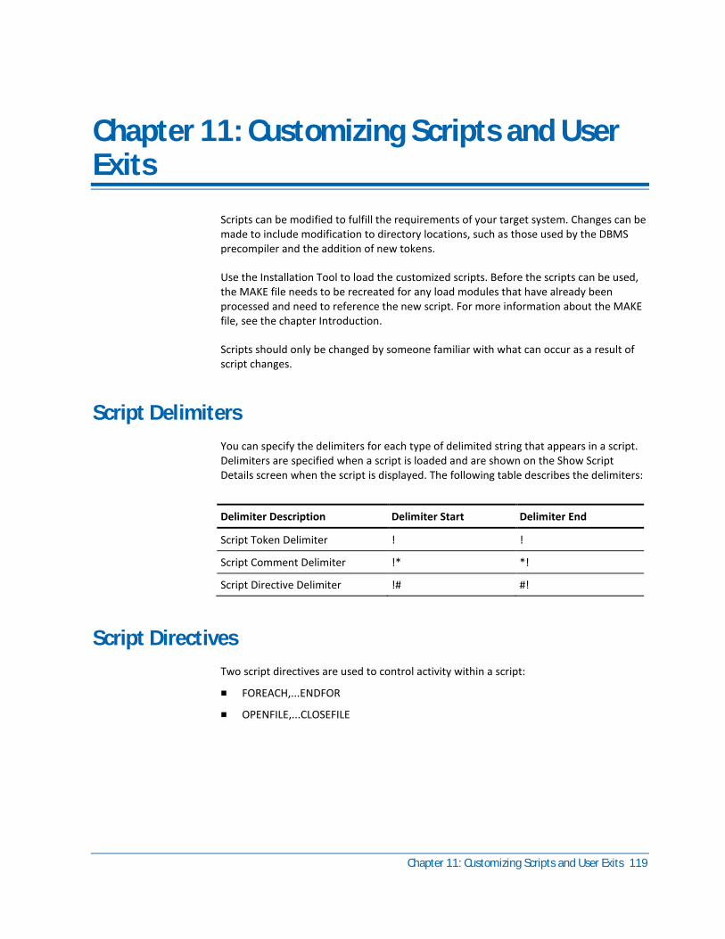
Chapter 11: Customizing Scripts and User Exits 119
Chapter 11: Customizing Scripts and User Exits
Scripts can be modified to fulfill the requirements of your target system. Changes can be made to include modification to directory locations, such as those used by the DBMS precompiler and the addition of new tokens.
Use the Installation Tool to load the customized scripts. Before the scripts can be used, the MAKE file needs to be recreated for any load modules that have already been processed and need to reference the new script. For more information about the MAKE file, see the chapter Introduction.
Scripts should only be changed by someone familiar with what can occur as a result of script changes.
Script Delimiters
You can specify the delimiters for each type of delimited string that appears in a script. Delimiters are specified when a script is loaded and are shown on the Show Script Details screen when the script is displayed. The following table describes the delimiters:
Delimiter Description Delimiter Start Delimiter End
Script Token Delimiter ! !
Script Comment Delimiter !* *!
Script Directive Delimiter !# #!
Script Directives
Two script directives are used to control activity within a script:
■ FOREACH,...ENDFOR
■ OPENFILE,...CLOSEFILE
Tokens
120 z/OS Implementation Toolset User Guide
FOREACH,...ENDFOR
The FOREACH,...ENDFOR script directive allows use of a looping structure to perform an action on every occurrence of a specified type. For example, the FOREACH LOAD_MODULE directive allows you to specify the action to be performed for each load module.
The objects that can appear as repeating group members are:
■ BUSINESS_SYSTEM
■ CLEAR_SCREEN_TRANCODE
■ DIALOG_FLOW_TRANCODE
■ EXT_AB_LIB
■ EXT_DBRM_LIB
■ EXTERNAL_AB
■ EXTERNAL_DBRM
■ LOAD_MODULE
■ SOURCE_MEMBER
■ STATIC_EXT_AB_LIB
■ SYS_LOAD_LIB
OPENFILE,...CLOSEFILE
The OPENFILE,...CLOSEFILE directive specifies a file location and name. It works in a manner similar to that of the FOREACH,...ENDFOR directive. OPENFILE directives within OPENFILE directives are not supported.
Tokens
A token is a generic name for a variable element of a script (MAKE command procedure). During the installation of a remote file, the Installation Tool interprets the script and replaces the tokens with information about the remote file to produce a complete command procedure.
There are three categories of tokens:
■ Environment Parameter
■ Location
■ Generalized Markup Language (GML)
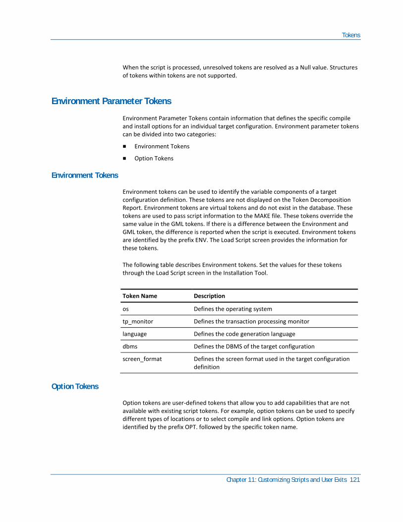
Tokens
Chapter 11: Customizing Scripts and User Exits 121
When the script is processed, unresolved tokens are resolved as a Null value. Structures of tokens within tokens are not supported.
Environment Parameter Tokens
Environment Parameter Tokens contain information that defines the specific compile and install options for an individual target configuration. Environment parameter tokens can be divided into two categories:
■ Environment Tokens
■ Option Tokens
Environment Tokens
Environment tokens can be used to identify the variable components of a target configuration definition. These tokens are not displayed on the Token Decomposition Report. Environment tokens are virtual tokens and do not exist in the database. These tokens are used to pass script information to the MAKE file. These tokens override the same value in the GML tokens. If there is a difference between the Environment and GML token, the difference is reported when the script is executed. Environment tokens are identified by the prefix ENV. The Load Script screen provides the information for these tokens.
The following table describes Environment tokens. Set the values for these tokens through the Load Script screen in the Installation Tool.
Token Name Description
os Defines the operating system
tp_monitor Defines the transaction processing monitor
language Defines the code generation language
dbms Defines the DBMS of the target configuration
screen_format Defines the screen format used in the target configuration definition
Option Tokens
Option tokens are user-defined tokens that allow you to add capabilities that are not available with existing script tokens. For example, option tokens can be used to specify different types of locations or to select compile and link options. Option tokens are identified by the prefix OPT. followed by the specific token name.
Tokens
122 z/OS Implementation Toolset User Guide
Option tokens can be assigned specific values when creating or updating a target, model, or business system definition. The values are set using the Options screen (accessed using F13) during target, model, or business system definition.
Option tokens are not used in the default scripts provided for the z/OS environment. If you elect to use Option tokens, the tokens must be added to the appropriate script before they are usable.
Option tokens are defined by customizing a script to use them.
Note: All script tokens are surrounded by the unique delimiters specified for a particular target system.
Important! Make sure that the script will still work properly if the option token values are not found and tokens resolve to nulls.
Making Option Tokens Effective
After a script has been modified, it must be loaded into the Installation Tool before it can be accessed.
If option tokens have been added to scripts associated with existing Target Configurations, then the MAKE file must be recreated before the option tokens are effective on remote files that have already been split.
Adding Values for Option Tokens
After the script is associated with a Target Configuration, users can identify token values when creating or updating a Target, Model, or BusSys definition. This is done on the Options screen, which is accessed from the Target Definition, Model Definition, or BusSys Definition screens by pressing F13.
It is important to know the token names when using the Options screen. The Options screen contains two columns that allow you to enter a token name and the value, but the option token names that apply are not listed.
Location and Library Tokens
When a MAKE procedure is created as a part of remote file installation, the location tokens are replaced with the actual library name where CA Gen generated components are stored when a remote file is installed.
All Location tokens are populated from the data entered on the Location screen of the Installation Tool. Location tokens are identified by the prefix LOC or LIB. (Library tokens are a form of Location token.)

Tokens
Chapter 11: Customizing Scripts and User Exits 123
The following table describes Location tokens. Location tokens can occur at target, model, and business system levels. Set the values for these tokens using the Location Screens in the Installation Tool.
Token Name Description
Source_lib The location of generated source split from remote files.
Ncal_load_lib* The location of unresolved load modules (output from compilation step).
Exe_load_lib* The location of executable load modules (fully resolved load modules).
Impl_load_lib* The location of implemented load modules. The install step copies modules from the Exec loadlib to the Impl loadlib.
DBRM_lib The location of DBRMs created by the DB2 compiler.
Inst_ctl_lib The location of load module ICM split from remote files.
Listing_lib The location of compiler listings (optional).
Clist_lib The location of generated MAKE procedures.
Tranmap_file The IEFAE file that associates trancodes to load modules.
Appl_clist_lib The location of generated commands to invoke an application under IEFAE (one command for each clear screen trancode).
MFS_source_lib The location of generated MFS code split from remote files.
Bndctl_lib The location of the binder control cards (optional).
Batch_JCL_lib This token is reserved for future use.
Idcams_ctl_lib The location of IDCAMS control statements split from DDL remote files.
DDL_lib The location of DDL statements split from DDL remote files.
RI_source_lib The location of source code for RI triggers split from RI trigger remote files.
RI_load_lib* The location of NCAL load modules created by compiling RI triggers.
RI_DBRM_lib The location of DBRMs for RI triggers.
RI_listing_lib The location of compiler listings for RI trigger modules (optional).
RI_Exec_lib* The location of RI executable load modules.
RI_Bndctl_lib The location of the RI Triggers binder control cards (optional).

Tokens
124 z/OS Implementation Toolset User Guide
Token Name Description
Batch_Exec_lib The location of the Batch executable dynamic and zlib load modules (optional).
Batch_Bndctl The location of the Batch executable binder control cards (optional).
Batch_RI_lib The location of the Batch executable dynamic RI Trigger load modules (optional).
Batch_RI_Bctl The location of the Batch dynamic RI Triggers binder control cards (optional).
Static_ncal_lib* The location of unresolved load modules (output from compilation step) for action blocks statically called by modules marked for Compatibility.
Static_list_lib The location of compiler listings for action bocks statically called by modules marked for Compatibility (optional).
Static_RI_ncal_lib* The location of NCAL load modules created for RI triggers compiled with the NODLL compiler option.
Static_RI_list_lib The location of compiler listings for RI trigger modules compiled with the NODLL compiler option (optional).
Note: * Data set must be created as a PDSE (DSNtype=library) data set.
Library tokens are an alternate token resolution structure available that concatenates all location occurrences into a search sequence. When the MAKE file executes, each location is searched in sequence until the component is located or the list is exhausted. This capability is limited to three components and is very useful for ensuring that common or system level components do not have to be copied into CA Gen specific locations before they are accessed.
Library tokens are identified by the prefix LIB. LIB tokens are used to support multiple External Action Block libraries, multiple External Action Block DBRM libraries, and multiple system load libraries. The following table describes Library tokens:
Token Name Description
Ext_ab_libs* The location of load libraries containing External Action Blocks. There is a maximum of 12 libraries.
Ext_DBRM_libs The location of DBRM libraries containing External Action Block DBRMs. There is a maximum of 12 libraries.
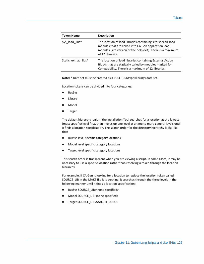
Tokens
Chapter 11: Customizing Scripts and User Exits 125
Token Name Description
Sys_load_libs* The location of load libraries containing site-specific load modules that are linked into CA Gen application load modules (site version of the help exit). There is a maximum of 12 libraries.
Static_ext_ab_libs* The location of load libraries containing External Action Blocks that are statically called by modules marked for Compatibility. There is a maximum of 12 libraries.
Note: * Data set must be created as a PDSE (DSNtype=library) data set.
Location tokens can be divided into four categories:
■ BusSys
■ Library
■ Model
■ Target
The default hierarchy logic in the Installation Tool searches for a location at the lowest (most specific) level first, then moves up one level at a time to more general levels until it finds a location specification. The search order for the directory hierarchy looks like this:
■ BusSys level specific category locations
■ Model level specific category locations
■ Target level specific category locations
This search order is transparent when you are viewing a script. In some cases, it may be necessary to use a specific location rather than resolving a token through the location hierarchy.
For example, if CA Gen is looking for a location to replace the location token called SOURCE_LIB in the MAKE file it is creating, it searches through the three levels in the following manner until it finds a location specification:
■ BusSys SOURCE_LIB:<none specified>
■ Model SOURCE_LIB:<none specified>
■ Target SOURCE_LIB:AAAC.IEF.COBOL
Tokens
126 z/OS Implementation Toolset User Guide
When the first location specification is found, AAAC.IEF.COBOL, is used to replace the location token in the MAKE file being created. In the example, the location specification is at the Target level. Because the Installation Tool automatically searches through the location hierarchy until a location is found, you can define locations with generic location tokens rather than separate tokens for each level. In the script, you do not need to include all the possible token names under which a location can be stored.
Generalized Markup Language Tokens
Generalized Markup Language (GML) is the language used in the ICM of each remote file generated through CA Gen. The information in the ICM defines the contents of the database, RI trigger set, or load module remote file. For database and RI trigger remote files, all of the components specified in the ICM are found in the remote file. For a load module remote file, the complete load module is defined in the ICM, regardless of the number of components included in the remote file. (This is done for maintenance purposes. It allows you to change and regenerate portions of a load module without changing its definition.)
An incomplete load module ICM can result if the subset used to generate the remote file does not contain all the elements for the load module.

Tokens
Chapter 11: Customizing Scripts and User Exits 127
The following is an example of how the GML is used in the ICM of an RI trigger remote file.
:remote target=MVS type=CASCADE.
:split member=CASCADE type=ICM.
:execdef
user=USERNM
date=92/12/12
time=15:27:32
os=NT
:source
model='ORDER ENTRY IV'
subset='ALL'
dateup=0000/00/00
timeup=00:00
saved=NO
schema=9.1.A5
level=9.1.A5.01
codepage=1252
:esource.
:systems
source=E:\MODELS\ORDER.IEF\COBOL\.
:esystems.
:execunit
language=COBOL
os=MVS
dbms=DB2
dbname=ORDERDB1
pcompat=YES
Tokens in GML are represented as equate statements, which have an identifier to the left of the equal sign and the variable data to the right of the equal sign. Not all of the equate statements shown in an ICM are used as tokens by the script.
When the equate statements are processed into tokens, they are assigned to one of the five GML token types. The GML token types used by CA Gen follow.
Business System Tokens
These tokens are set during business system definition:
Token Name Description
SOURCE The source directory on the development workstation. This value is found in the :systems section of the ICM of each remote file associated with this business system as source=.
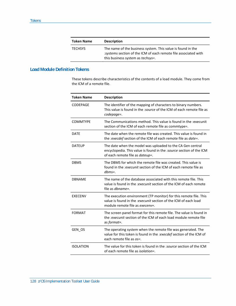
Tokens
128 z/OS Implementation Toolset User Guide
Token Name Description
TECHSYS The name of the business system. This value is found in the :systems section of the ICM of each remote file associated with this business system as techsys=.
Load Module Definition Tokens
These tokens describe characteristics of the contents of a load module. They come from the ICM of a remote file.
Token Name Description
CODEPAGE The identifier of the mapping of characters to binary numbers. This value is found in the :source of the ICM of each remote file as codepage=.
COMMTYPE The Communications method. This value is found in the :execunit section of the ICM of each remote file as commtype=.
DATE The date when the remote file was created. This value is found in the :execdef section of the ICM of each remote file as date=.
DATEUP The date when the model was uploaded to the CA Gen central encyclopedia. This value is found in the :source section of the ICM of each remote file as dateup=.
DBMS The DBMS for which the remote file was created. This value is found in the :execunit section of the ICM of each remote file as dbms=.
DBNAME The name of the database associated with this remote file. This value is found in the :execunit section of the ICM of each remote file as dbname=.
EXECENV The execution environment (TP monitor) for this remote file. This value is found in the :execunit section of the ICM of each load module remote file as execenv=.
FORMAT The screen panel format for this remote file. The value is found in the :execunit section of the ICM of each load module remote file as format=.
GEN_OS The operating system when the remote file was generated. The value for this token is found in the :execdef section of the ICM of each remote file as os=.
ISOLATION The value for this token is found in the :source section of the ICM of each remote file as isolation=.
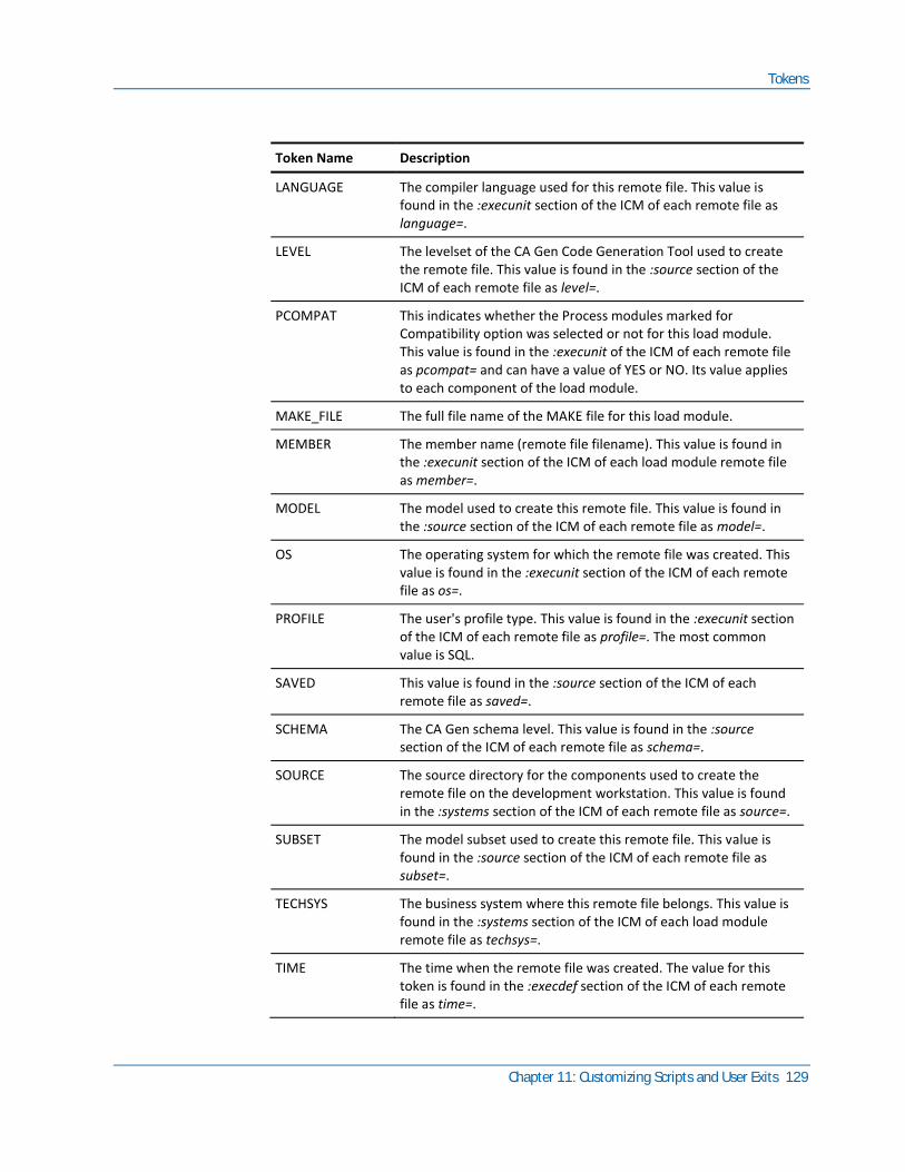
Tokens
Chapter 11: Customizing Scripts and User Exits 129
Token Name Description
LANGUAGE The compiler language used for this remote file. This value is found in the :execunit section of the ICM of each remote file as language=.
LEVEL The levelset of the CA Gen Code Generation Tool used to create the remote file. This value is found in the :source section of the ICM of each remote file as level=.
PCOMPAT This indicates whether the Process modules marked for Compatibility option was selected or not for this load module. This value is found in the :execunit of the ICM of each remote file as pcompat= and can have a value of YES or NO. Its value applies to each component of the load module.
MAKE_FILE The full file name of the MAKE file for this load module.
MEMBER The member name (remote file filename). This value is found in the :execunit section of the ICM of each load module remote file as member=.
MODEL The model used to create this remote file. This value is found in the :source section of the ICM of each remote file as model=.
OS The operating system for which the remote file was created. This value is found in the :execunit section of the ICM of each remote file as os=.
PROFILE The user's profile type. This value is found in the :execunit section of the ICM of each remote file as profile=. The most common value is SQL.
SAVED This value is found in the :source section of the ICM of each remote file as saved=.
SCHEMA The CA Gen schema level. This value is found in the :source section of the ICM of each remote file as schema=.
SOURCE The source directory for the components used to create the remote file on the development workstation. This value is found in the :systems section of the ICM of each remote file as source=.
SUBSET The model subset used to create this remote file. This value is found in the :source section of the ICM of each remote file as subset=.
TECHSYS The business system where this remote file belongs. This value is found in the :systems section of the ICM of each load module remote file as techsys=.
TIME The time when the remote file was created. The value for this token is found in the :execdef section of the ICM of each remote file as time=.

Tokens
130 z/OS Implementation Toolset User Guide
Token Name Description
TIMEUP The time when the model was uploaded to the central encyclopedia. This value is found in the :source section of the ICM of each remote file as timeup=.
USER The user who created the remote file. The value for this token is found in the :execdef section of the ICM of each remote file as user=.
VDFMEMBER The View Definition table source member name. This value is not used in z/OS.
Load Module Member Tokens
These tokens describe characteristics of one portion of a load module (such as a procedure step or action block). They come from the ICM of a remote file.
Token Name Description
ABTYPE The action block type. Appears only if the load module member is an action block.
ACFMEMBER The Attribute Configuration File source member associated with the procedure step. This is not used on z/OS.
CLRTRAN The clear screen transaction code. CLRTRAN only appears if the load module member is a procedure step. The value for this token is found in the :pstep definition in the ICM as clrtran=.
CREATE Indicates whether this member may perform an SQL CREATE statement. The value for this token is found in the :pstep, :acblk, :entity, and :relation definitions in the ICM of load module and RI remote files as create=.
DELETE Indicates whether this member may perform an SQL DELETE statement. The value for this token is found in the :pstep, :entity, and :relation definitions in the ICM of load module and RI remote files as delete=.
DEVICE The MFS format name.
DLGTRAN The dialog flow transaction code. DLGTRAN only appears if the load module member is a procedure step. The value for this token is found in the :pstep definition in the ICM as dlgtran=.
INPUT The MFS mid name.
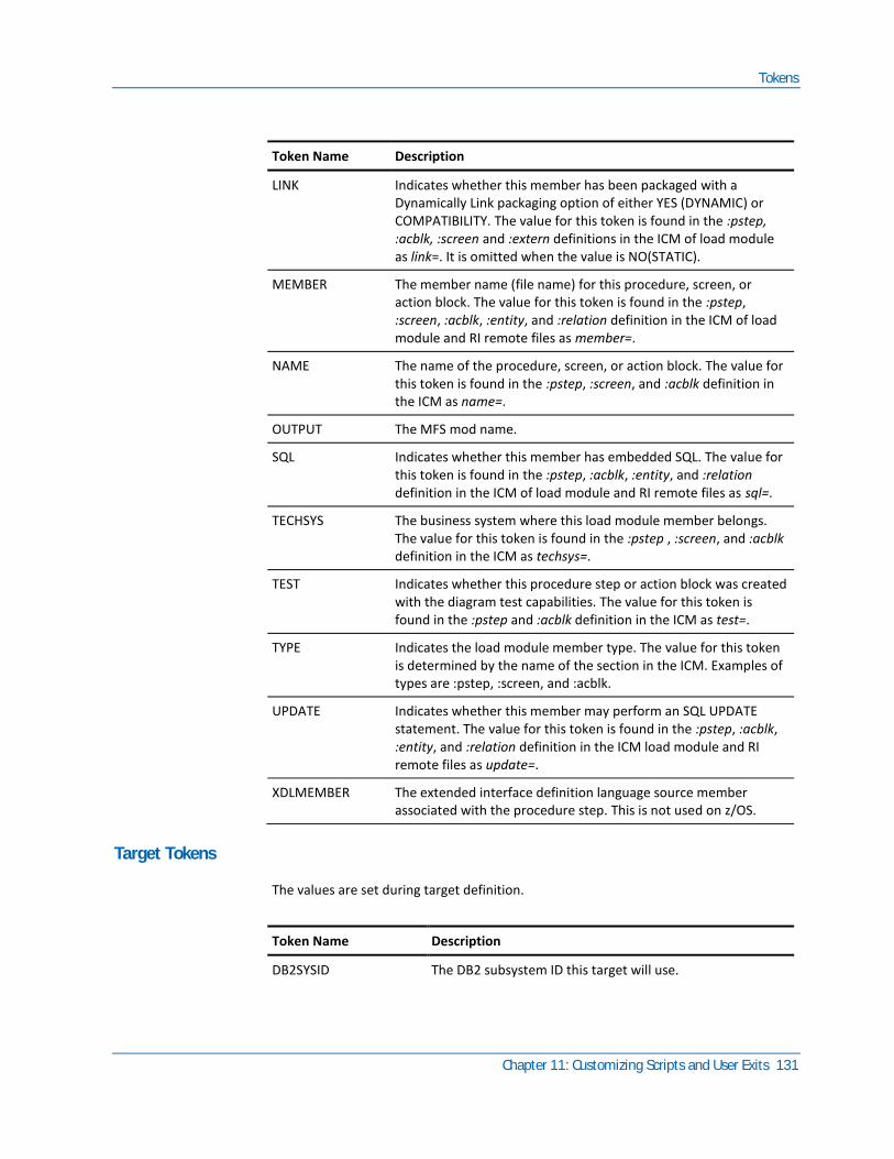
Tokens
Chapter 11: Customizing Scripts and User Exits 131
Token Name Description
LINK Indicates whether this member has been packaged with a Dynamically Link packaging option of either YES (DYNAMIC) or COMPATIBILITY. The value for this token is found in the :pstep, :acblk, :screen and :extern definitions in the ICM of load module as link=. It is omitted when the value is NO(STATIC).
MEMBER The member name (file name) for this procedure, screen, or action block. The value for this token is found in the :pstep, :screen, :acblk, :entity, and :relation definition in the ICM of load module and RI remote files as member=.
NAME The name of the procedure, screen, or action block. The value for this token is found in the :pstep, :screen, and :acblk definition in the ICM as name=.
OUTPUT The MFS mod name.
SQL Indicates whether this member has embedded SQL. The value for this token is found in the :pstep, :acblk, :entity, and :relation definition in the ICM of load module and RI remote files as sql=.
TECHSYS The business system where this load module member belongs. The value for this token is found in the :pstep , :screen, and :acblk definition in the ICM as techsys=.
TEST Indicates whether this procedure step or action block was created with the diagram test capabilities. The value for this token is found in the :pstep and :acblk definition in the ICM as test=.
TYPE Indicates the load module member type. The value for this token is determined by the name of the section in the ICM. Examples of types are :pstep, :screen, and :acblk.
UPDATE Indicates whether this member may perform an SQL UPDATE statement. The value for this token is found in the :pstep, :acblk, :entity, and :relation definition in the ICM load module and RI remote files as update=.
XDLMEMBER The extended interface definition language source member associated with the procedure step. This is not used on z/OS.
Target Tokens
The values are set during target definition.
Token Name Description
DB2SYSID The DB2 subsystem ID this target will use.
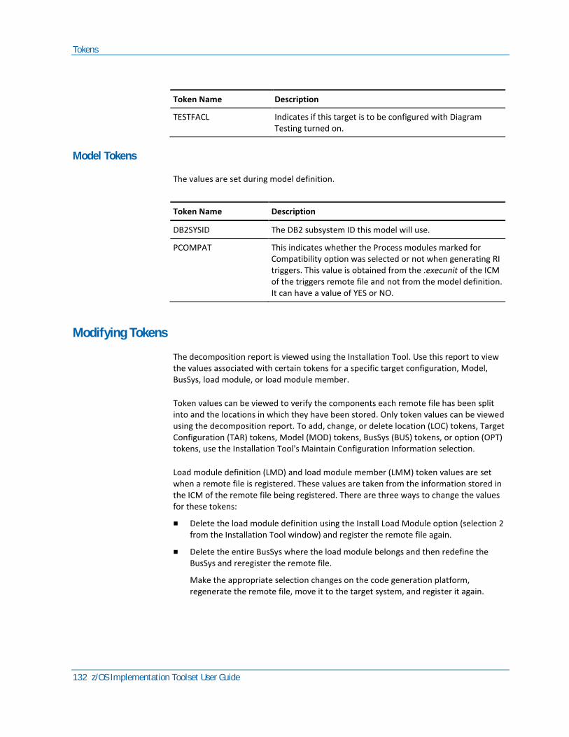
Tokens
132 z/OS Implementation Toolset User Guide
Token Name Description
TESTFACL Indicates if this target is to be configured with Diagram Testing turned on.
Model Tokens
The values are set during model definition.
Token Name Description
DB2SYSID The DB2 subsystem ID this model will use.
PCOMPAT This indicates whether the Process modules marked for Compatibility option was selected or not when generating RI triggers. This value is obtained from the :execunit of the ICM of the triggers remote file and not from the model definition. It can have a value of YES or NO.
Modifying Tokens
The decomposition report is viewed using the Installation Tool. Use this report to view the values associated with certain tokens for a specific target configuration, Model, BusSys, load module, or load module member.
Token values can be viewed to verify the components each remote file has been split into and the locations in which they have been stored. Only token values can be viewed using the decomposition report. To add, change, or delete location (LOC) tokens, Target Configuration (TAR) tokens, Model (MOD) tokens, BusSys (BUS) tokens, or option (OPT) tokens, use the Installation Tool's Maintain Configuration Information selection.
Load module definition (LMD) and load module member (LMM) token values are set when a remote file is registered. These values are taken from the information stored in the ICM of the remote file being registered. There are three ways to change the values for these tokens:
■ Delete the load module definition using the Install Load Module option (selection 2 from the Installation Tool window) and register the remote file again.
■ Delete the entire BusSys where the load module belongs and then redefine the BusSys and reregister the remote file.
Make the appropriate selection changes on the code generation platform, regenerate the remote file, move it to the target system, and register it again.

Tokens
Chapter 11: Customizing Scripts and User Exits 133
Customizing and Installing User Exits
For information about Customizing and Installing User Exits, see User Exit Reference Guide.

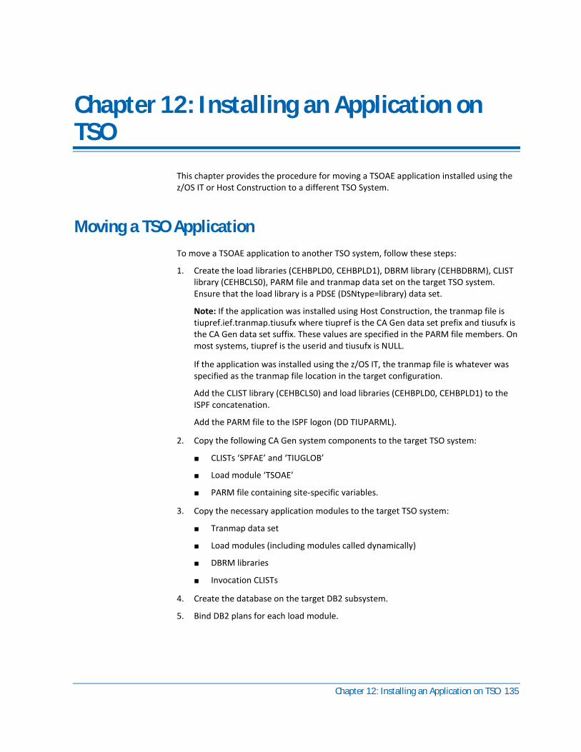
Chapter 12: Installing an Application on TSO 135
Chapter 12: Installing an Application on TSO
This chapter provides the procedure for moving a TSOAE application installed using the z/OS IT or Host Construction to a different TSO System.
Moving a TSO Application
To move a TSOAE application to another TSO system, follow these steps:
1. Create the load libraries (CEHBPLD0, CEHBPLD1), DBRM library (CEHBDBRM), CLIST library (CEHBCLS0), PARM file and tranmap data set on the target TSO system. Ensure that the load library is a PDSE (DSNtype=library) data set.
Note: If the application was installed using Host Construction, the tranmap file is tiupref.ief.tranmap.tiusufx where tiupref is the CA Gen data set prefix and tiusufx is the CA Gen data set suffix. These values are specified in the PARM file members. On most systems, tiupref is the userid and tiusufx is NULL.
If the application was installed using the z/OS IT, the tranmap file is whatever was specified as the tranmap file location in the target configuration.
Add the CLIST library (CEHBCLS0) and load libraries (CEHBPLD0, CEHBPLD1) to the ISPF concatenation.
Add the PARM file to the ISPF logon (DD TIUPARML).
2. Copy the following CA Gen system components to the target TSO system:
■ CLISTs ‘SPFAE’ and ‘TIUGLOB’
■ Load module ‘TSOAE’
■ PARM file containing site-specific variables.
3. Copy the necessary application modules to the target TSO system:
■ Tranmap data set
■ Load modules (including modules called dynamically)
■ DBRM libraries
■ Invocation CLISTs
4. Create the database on the target DB2 subsystem.
5. Bind DB2 plans for each load module.

Moving a TSO Application
136 z/OS Implementation Toolset User Guide
6. Grant DB2 access to the appropriate users.
7. Customize an ISPF panel to call the invocation CLIST for the appropriate clear screen trancode. This is usually the clear screen trancode for the application’s primary window.
Index 137
Index
A
Abends handled by Dialog Manager • 86 Action Diagram Trace Panel • 89
Appearance Commands • 89 COLOR • 89 COLOR TEXT • 89 HILIGHT • 89
Commands • 89 DOWN • 89 EXIT • 89 HELP • 89 RFIND • 89 SKIP • 89 TRACE • 89 UP • 89
CommandsFIND • 89 CommandsLOCATE • 89
Action Diagram View Display Panel • 92 Commands • 92
DOWN • 92 FIND • 92 HELP • 92 LEFT nnn • 92 RFIND • 92 RIGHT nnn • 92 UP • 92
Adding values for option tokens • 122 Application maintenance • 97, 111
Changing • 97 Application production • 110, 111
CICS environment • 111 IEFAE environment • 110
Application Test Facility • 77 Application testing • 109
B
Background Utility • 99, 105 Build JCL member • 99 Execution parameters • 105 Providing job card information • 99
Business system • 37, 39, 40 Definition • 37 Deleting • 40 Modifying • 39
C
Cascade IP, processing • 45 CICS • 78, 80, 111
Debug Trace Facility considerations • 78 Executing test • 80 Testing • 80
CICS Debug Trace Facility user interface • 80 Complete testing and return to CA Gen • 86 Compose the Load Module MAKE File • 17 Copying application module • 135 Copying component • 135 Creating • 43, 47, 135
application database • 43 Executable load module • 47 Library • 135
Creating the Executable Load Modules • 47, 48, 49 Processing • 48 Reinstalling • 49 Toolset • 47
Customizing • 135 Panel • 135
D
DB2 subsystem • 84 Debug Trace Facility • 77, 80, 81, 88
Commands • 81 Parameters • 81 Starting • 80
Deleting • 34, 37, 40 Business system • 40 Model • 37 Target • 34
Delimiter, script • 119 Directive, script • 119 Display system variables • 95
CURRENT DATE • 95 CURRENT TIME • 95 INFORMATION MESSAGE • 95 PRINTER ID • 95 SYSTEM COMMAND • 95 TERMINAL ID • 95 TRANCODE • 95 USER ID • 95
Duplicating a target • 32

138 z/OS Implementation Toolset User Guide
E
End function key assignment • 84 Environment • 121
Parameter token • 121 Token • 121
Executable Load Module • 47 Execute the Load Module MAKE File • 17 Executing test • 80, 83
Application Test Facility • 83 CICS • 80
External Action Blocks • 51, 52, 53, 54, 55, 57, 61, 62, 63, 66, 67, 68, 69, 70, 74, 75 Create • 55
Action Block • 55 Calling Procedure Step • 55 External Action Logic • 55
Defining • 54 Design • 54 Disabling High Performance View Passing • 57 Generation • 61, 62, 63, 66, 67, 68, 69, 70
As Interface to Subroutine • 63 CA Gen Tasks • 61 Compile • 69 Customize External Action Logic • 63 Load Module Structure • 70 Locate the External Action Block stub • 62 Modifying • 67 IEF-RUNTIME-PARM1 • 67 IEF-RUNTIME-PARM2 • 67 PSMRG-EAB-DATA • 67 W-IA • 67 W-OA • 67 Parameters • 67 PSMRG-EAB-DATA Parameters • 68 Using Repeating Groups • 69 Varying Length Fields • 68 W-IA and W-OA Parameters • 68 With Embedded Customized Codes • 66
High Performance View Passing • 55 EXPORT_CUSTOMER • 55 GLOBDATA • 55 IEF-RUNTIME-PARM1 • 55 IEF-RUNTIME-PARM2 • 55 Import/Export View W-IA or W-IO • 55 IMPORT-NON-REPEATING-GR-0005GV • 55 PS-EAB-DATA • 55
Implementing • 53 Installation • 74, 75
Identify If External Action Block Exists • 75 Load Module • 75 Transfer the Remote • 74
Prerequisite • 51 READ_HISTORY • 54 Terms • 52
G
Generalized Markup Language tokens • 126 Generating IPs for testing • 79
H
How to • 28, 32, 34, 35 Add a Model • 35 Add a Target • 28 Delete a Target • 34 Duplicate a Target • 32 Modify a Target • 32
I
IEFAE • 12, 110 Application Execution Facility • 12 Environment • 110
Install the Cascade IP • 43 Install the Load Module • 18 Installing • 14, 15
Process • 14 Step 1 - Load Scripts • 14 Step 2 - Define target configuration • 14 Step 3 - Transfer implementation packages • 15 Step 4 - Complete construction of code • 15
Installing an application on TSO • 79, 135 Bind DB2 plans • 135 Copying application module • 135 Copying component • 135 Creating database • 135 Creating library • 135 Customizing panel • 135 Granting access • 135 In test environment • 79
IT • 11, 43 Before you begin • 43 Navigating through • 43 Process the DDL IP • 43
J
JCL member • 99 Job card information, providing • 99

Index 139
L
Load Module • 47, 48, 49, 117 Creating executable load module • 47 Packaging • 117 Processing the IP • 48 Reinstalling • 49
Loading scripts • 19 Location and library tokens • 122
M
Maintenance, application • 111 Making option tokens effective • 122 Matching Export Views • 58
External Action Block • 58 READ_HISTORY • 58
Matching Import Views • 58 Model • 34, 35, 37
Deleting • 37 Modifying • 35
Modifying • 39 Business system • 39
O
Online load module • 85 Option tokens • 121, 122
Adding values • 122 Making effective • 122
P
Prerequisites to loading scripts • 21 Process the Cascade IP • 15, 45
Toolset • 45 Process the DDL IP • 15, 43 Process the Load Module • 16 Processing • 45
Cascade IP • 45 Production • 110, 111
CICS environment • 111 IEFAE environment • 110
R
Register and Validate the IP • 16 Reinstalling a load module • 49 Runtime routine - IT • 13
S
Scripts • 21, 23, 119
Delimiters • 119 Directives • 119 Prerequisites to loading • 21 Prerequisites to viewing • 23 Supplied • 21
Split the IP • 17 SYSLIBS • 84 System variables, displaying • 95
T
Target • 27, 28, 32, 34, 35, 37, 39, 40 Business system definition • 37 Definition • 28 Deleting • 34 Deleting a business system • 40 Deleting a model • 37 Duplicating • 32 Model definition • 34 Modifying a business system • 39 Modifying a model • 35 Prerequisites • 27
Testing application • 77, 78, 79, 80, 83, 84, 85, 86, 88, 89, 92, 95, 97 Abend • 86 Accessing other debug panel • 92 Action Diagram Trace panel • 89 Application load library • 84 Application Test Facility • 79 application testing • 77 Batch Load Module • 86
Runtime errors • 86 CICS Debug Trace Facility considerations • 78 CICS testing • 80 Common testing error • 97 Complete and return to AllFusion Gen • 86 Creating executable • 80 DB2 subsystem • 84 Debug Trace Facility • 88 Displaying modify view • 92 Displaying system variables • 95 End Function key assignment • 84 Executing test under Application Test Facility • 83 Executing test under CICS • 80 Generating IPs for testing • 79 Generating with debug support • 79 Installing in test environment • 79 Making changes to an application • 97 Online load module • 85
140 z/OS Implementation Toolset User Guide
Rerunning a Failed Batch Job • 86 Specifying the test execution environment • 83 Testing • 84 Testing SYSLIBS • 84 Trace action block calls • 88 Trace Facility display interface • 78
Testing Applications • 77, 80, 81 Application Test Facility considerations • 77 CICS DTF user interface • 80 Considerations • 77 DTF commands • 81 DTF parameters • 81 Starting_DTF • 80
Tokens • 120, 121, 122, 126, 132 Adding values for option • 122 Environment • 121 Environment parameter • 121 Generalized Markup Language • 126 Location and library • 122 Making option tokens effective • 122 Modifying • 132 Option • 121
Toolset, navigating through • 20 Trace action block calls • 78, 88
Debug Trace Facility • 88 Trace Facility Display Interface • 78
TSO, installing an application • 135
V
Viewing scripts • 23