ca gen gen 8 5-enu/bookshelf... · ca gen contact ca technologies contact ca support for your...
TRANSCRIPT

Distributed Processing - Client Manager User Guide
Release 8.5
CA Gen

This Documentation, which includes embedded help systems and electronically distributed materials, (hereinafter referred to as the “Documentation”) is for your informational purposes only and is subject to change or withdrawal by CA at any time.
This Documentation may not be copied, transferred, reproduced, disclosed, modified or duplicated, in whole or in part, without the prior written consent of CA. This Documentation is confidential and proprietary information of CA and may not be disclosed by you or used for any purpose other than as may be permitted in (i) a separate agreement between you and CA governing your use of the CA software to which the Documentation relates; or (ii) a separate confidentiality agreement between you and CA.
Notwithstanding the foregoing, if you are a licensed user of the software product(s) addressed in the Documentation, you may print or otherwise make available a reasonable number of copies of the Documentation for internal use by you and your employees in connection with that software, provided that all CA copyright notices and legends are affixed to each reproduced copy.
The right to print or otherwise make available copies of the Documentation is limited to the period during which the applicable license for such software remains in full force and effect. Should the license terminate for any reason, it is your responsibility to certify in writing to CA that all copies and partial copies of the Documentation have been returned to CA or destroyed.
TO THE EXTENT PERMITTED BY APPLICABLE LAW, CA PROVIDES THIS DOCUMENTATION “AS IS” WITHOUT WARRANTY OF ANY KIND, INCLUDING WITHOUT LIMITATION, ANY IMPLIED WARRANTIES OF MERCHANTABILITY, FITNESS FOR A PARTICULAR PURPOSE, OR NONINFRINGEMENT. IN NO EVENT WILL CA BE LIABLE TO YOU OR ANY THIRD PARTY FOR ANY LOSS OR DAMAGE, DIRECT OR INDIRECT, FROM THE USE OF THIS DOCUMENTATION, INCLUDING WITHOUT LIMITATION, LOST PROFITS, LOST INVESTMENT, BUSINESS INTERRUPTION, GOODWILL, OR LOST DATA, EVEN IF CA IS EXPRESSLY ADVISED IN ADVANCE OF THE POSSIBILITY OF SUCH LOSS OR DAMAGE.
The use of any software product referenced in the Documentation is governed by the applicable license agreement and such license agreement is not modified in any way by the terms of this notice.
The manufacturer of this Documentation is CA.
Provided with “Restricted Rights.” Use, duplication or disclosure by the United States Government is subject to the restrictions set forth in FAR Sections 12.212, 52.227-14, and 52.227-19(c)(1) - (2) and DFARS Section 252.227-7014(b)(3), as applicable, or their successors.
Copyright © 2013 CA. All rights reserved. All trademarks, trade names, service marks, and logos referenced herein belong to their respective companies.
CA Technologies Product References
This document references the following CA Technologies products:
■ CA Gen
Contact CA Technologies
Contact CA Support
For your convenience, CA Technologies provides one site where you can access the information that you need for your Home Office, Small Business, and Enterprise CA Technologies products. At http://ca.com/support, you can access the following resources:
■ Online and telephone contact information for technical assistance and customer services
■ Information about user communities and forums
■ Product and documentation downloads
■ CA Support policies and guidelines
■ Other helpful resources appropriate for your product
Providing Feedback About Product Documentation
If you have comments or questions about CA Technologies product documentation, you can send a message to [email protected].
To provide feedback about CA Technologies product documentation, complete our short customer survey which is available on the CA Support website at http://ca.com/docs.

Contents 5
Contents
Chapter 1: Introduction 9
Who Should Read This Guide ..................................................................................................................................... 11
Visual Studio Support ................................................................................................................................................. 12
Related Information ................................................................................................................................................... 12
Chapter 2: Client Manager Overview 15
Concepts and Definitions ........................................................................................................................................... 15
Distributed Processing Application ..................................................................................................................... 15
Distributed Processing Client .............................................................................................................................. 16
Distributed Processing Server ............................................................................................................................. 16
Cooperative Flow ................................................................................................................................................ 16
Common Format Buffer ...................................................................................................................................... 16
Client Workstation .............................................................................................................................................. 16
Server Machine ................................................................................................................................................... 17
Communications Bridge ...................................................................................................................................... 17
Client Manager Client Applications ..................................................................................................................... 18
Server Execution Environments .......................................................................................................................... 19
IPv6 ...................................................................................................................................................................... 20
Single-Instance Versus Multi-Instance Client Manager.............................................................................................. 20
Single-Instance Client Manager .......................................................................................................................... 20
Multi-Instance Client Manager ........................................................................................................................... 21
Client Manager Features ............................................................................................................................................ 22
Client and Server Connections ................................................................................................................................... 23
Client Communications ....................................................................................................................................... 23
Server Communications ...................................................................................................................................... 23
LU6.2 (CPI-C) ....................................................................................................................................................... 24
TCP/IP (Sockets) .................................................................................................................................................. 24
RSC/MP (NonStop Remote Server Call) .............................................................................................................. 24
Other APIs ........................................................................................................................................................... 25
Client Manager Transaction Routing .......................................................................................................................... 25
Directory Services User Exit ................................................................................................................................ 26
Default Server ..................................................................................................................................................... 26
Security ....................................................................................................................................................................... 27
Confirming DPC/DPS Communications ...................................................................................................................... 27
Transaction Statistics .......................................................................................................................................... 28
Customizable User Exits ...................................................................................................................................... 28
6 Distributed Processing - Client Manager User Guide
Default Configuration and Log file Locations ...................................................................................................... 28
Chapter 3: General Configuration 31
Client Manager Installation ........................................................................................................................................ 31
First Start of Client Manager After Install .................................................................................................................. 31
Starting the Client Manager ....................................................................................................................................... 32
Desktop Start Menu ............................................................................................................................................ 32
Desktop Shortcut Icon ......................................................................................................................................... 32
Command Prompt ............................................................................................................................................... 33
Client Manager Setup Dialog ...................................................................................................................................... 34
File Description List ............................................................................................................................................. 35
Browse Button .................................................................................................................................................... 36
Rename Button ................................................................................................................................................... 36
File Browser......................................................................................................................................................... 36
Logging Level ....................................................................................................................................................... 37
Default Security Parameters ............................................................................................................................... 37
Dir. Srvcs. Status .................................................................................................................................................. 38
Auto-Connect to Server....................................................................................................................................... 39
Auto-Reset Server Connection ............................................................................................................................ 39
Chapter 4: Configuring the Client Manager for Client Communications 41
Single-Instance Client Manager .................................................................................................................................. 41
Multi-Instance Client Manager .................................................................................................................................. 42
Client Manager ID User Exit ................................................................................................................................ 43
Chapter 5: Configuring Client Manager Server Connections 45
Server Configuration .................................................................................................................................................. 46
Transport API – Additional Details ............................................................................................................................. 48
LU 6.2 CPI-C Connections .................................................................................................................................... 48
TCP/IP Socket Connections ................................................................................................................................. 51
z/OS CICS TCP/IP Direct Connect ........................................................................................................................ 60
NonStop RSC/MP Connections ........................................................................................................................... 61
Other API ............................................................................................................................................................. 65
Chapter 6: Transaction Routing 67
Directory Services User Exit ....................................................................................................................................... 68
NEXTLOCATION ................................................................................................................................................... 69
Transaction Code ................................................................................................................................................ 70
Default Server ..................................................................................................................................................... 70
Contents 7
Directory Services DLL Functions ............................................................................................................................... 71
Enable Client Manager Directory Services .......................................................................................................... 72
Directory Services and Client Manager Summary ...................................................................................................... 73
Configure a Default Server .................................................................................................................................. 74
Transaction Routing Events Summary ................................................................................................................ 74
Chapter 7: Server Access Security Using User ID and Password 77
Terminology ............................................................................................................................................................... 77
DPC Application Security Responsibilities .................................................................................................................. 81
Client Manager Security Responsibilities ................................................................................................................... 82
Client Manager Retrieving the Security Data ...................................................................................................... 83
Setting Target Server Security Parameters ......................................................................................................... 83
Client Manager Default Security Parameters...................................................................................................... 85
Derived Security Level Details ............................................................................................................................. 85
Client Manager Logon Dialog .............................................................................................................................. 87
Using Derived Security Data ................................................................................................................................ 88
Decryption of Common Format Buffer ...................................................................................................................... 89
Client Manager DECRYPT User Exit ..................................................................................................................... 89
Translating UserID and Password ............................................................................................................................... 90
CIDE_INIT() .......................................................................................................................................................... 90
CIDE_PROC() ........................................................................................................................................................ 90
Chapter 8: Saving Configuration Files 91
Saving the Client Manager Configuration .................................................................................................................. 92
Changing Configuration File Names .................................................................................................................... 93
Chapter 9: Testing the Client Manager 95
Server Configuration .................................................................................................................................................. 95
Sending a Test Transaction......................................................................................................................................... 96
The ECHO Transaction ................................................................................................................................................ 96
Testing a Server Connection Using the ECHO Transaction ......................................................................................... 98
Using a User-Written Test Transaction .................................................................................................................... 103
Using a Client Application to Test Connectivity ....................................................................................................... 103
Chapter 10: Client Manager Server Flow Statistics 105
Statistics - Summary Dialog ...................................................................................................................................... 105
Statistics - Refresh Parameters Dialog ..................................................................................................................... 106
Refresh On/Off .................................................................................................................................................. 106
Interval .............................................................................................................................................................. 106
8 Distributed Processing - Client Manager User Guide
Appendix A: Error Messages 107
Setting the Logging Level to Tracing......................................................................................................................... 107
Appendix B: User Exits 109
Index 111
Chapter 1: Introduction 9
Chapter 1: Introduction
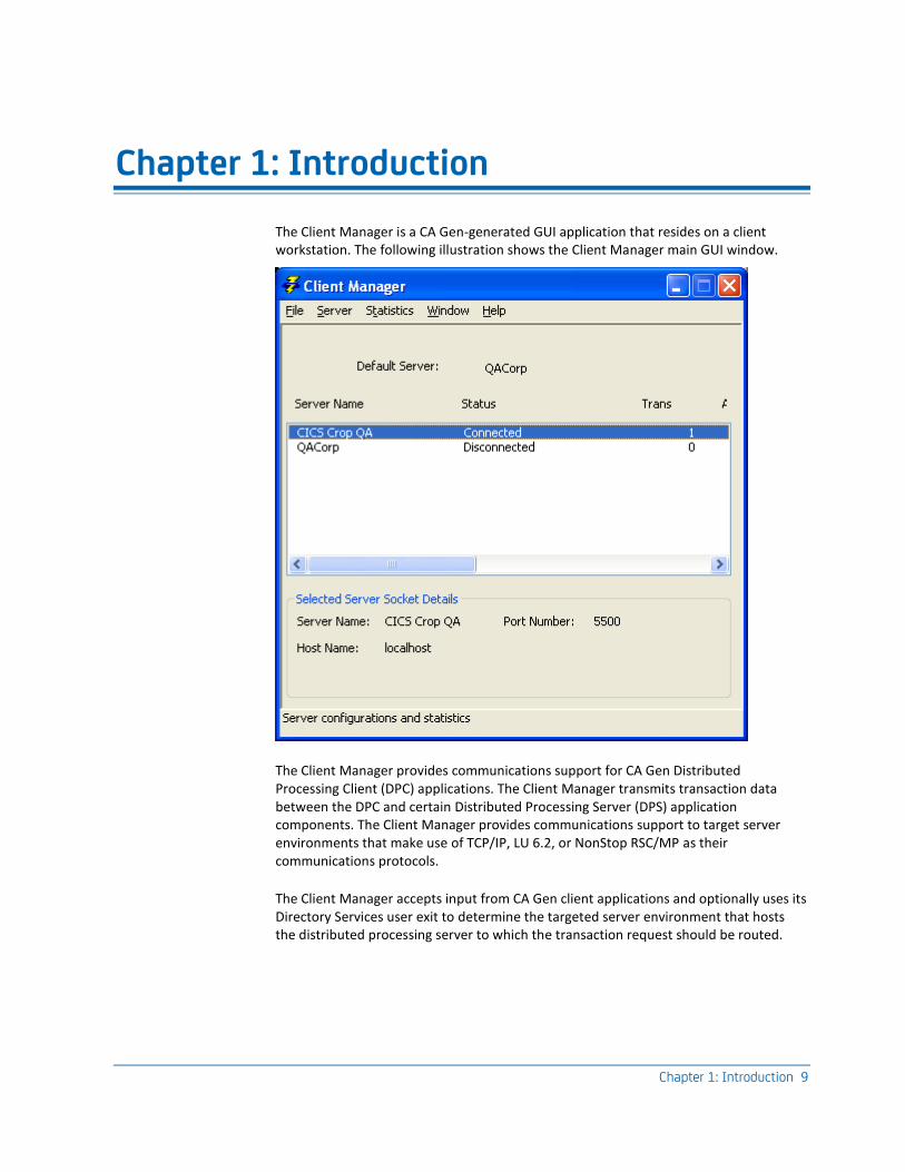
The Client Manager is a CA Gen-generated GUI application that resides on a client workstation. The following illustration shows the Client Manager main GUI window.
The Client Manager provides communications support for CA Gen Distributed Processing Client (DPC) applications. The Client Manager transmits transaction data between the DPC and certain Distributed Processing Server (DPS) application components. The Client Manager provides communications support to target server environments that make use of TCP/IP, LU 6.2, or NonStop RSC/MP as their communications protocols.
The Client Manager accepts input from CA Gen client applications and optionally uses its Directory Services user exit to determine the targeted server environment that hosts the distributed processing server to which the transaction request should be routed.
Who Should Read This Guide
10 Distributed Processing - Client Manager User Guide
The Client Manager is capable of concurrently serving many CA Gen Client requests targeting a variety of CA Gen servers. The Client Manager provides the ability for individual CA Gen servers to be hosted by different server environments. The Client Manager can simultaneously support the use of different transports protocols when processing a collection of cooperative flow requests.
The Client Manager and the clients it serves communicate using a collection of Windows inter-process communications mechanisms. These mechanisms include mailslots, shared memory, and named semaphores.
The Client Manager can be configured to communicate with the target server environments hosting the CA Gen distributed processing servers through one or more of the following supported communication protocols and APIs:
■ TCP/IP (Sockets)
■ LU 6.2 (CPI-C)
■ NonStop Remote Server Call (RSC/MP)
The following diagram illustrates the server transports supported by a Client Manager:
The following table identifies target server environments capable of being served by a Client Manager:
Server Environment CPI/C (LU 6.2) Sockets (TCP/IP)
NonStop Remote Server Call
(RSC/MP)
z/OS CICS X X n/a
z/OS IMS X X n/a
Transaction Enabler n/a X n/a
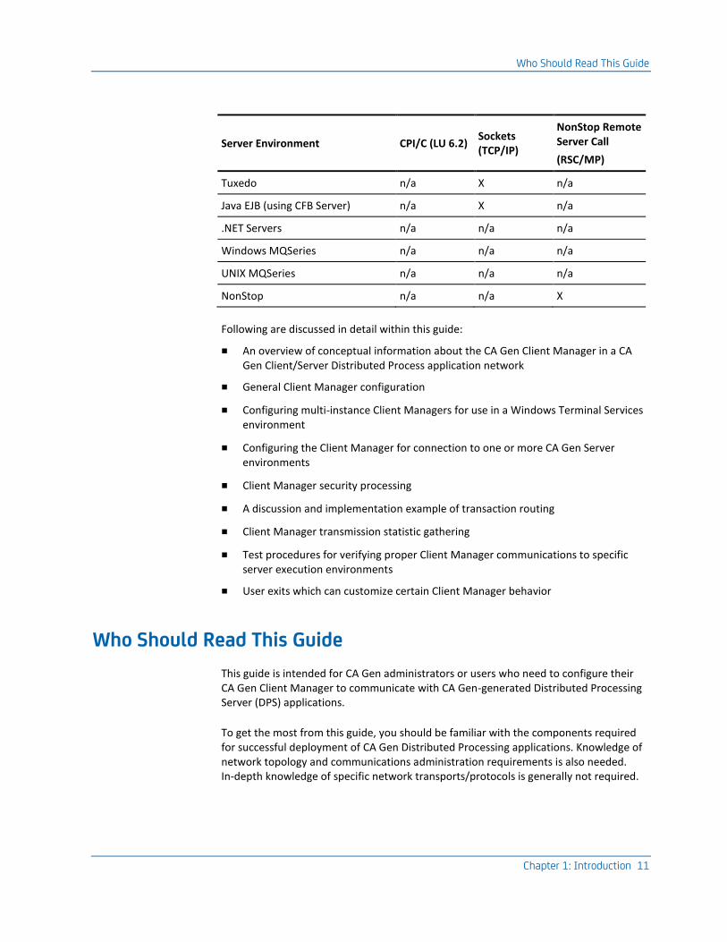
Who Should Read This Guide
Chapter 1: Introduction 11
Server Environment CPI/C (LU 6.2) Sockets (TCP/IP)
NonStop Remote Server Call
(RSC/MP)
Tuxedo n/a X n/a
Java EJB (using CFB Server) n/a X n/a
.NET Servers n/a n/a n/a
Windows MQSeries n/a n/a n/a
UNIX MQSeries n/a n/a n/a
NonStop n/a n/a X
Following are discussed in detail within this guide:
■ An overview of conceptual information about the CA Gen Client Manager in a CA Gen Client/Server Distributed Process application network
■ General Client Manager configuration
■ Configuring multi-instance Client Managers for use in a Windows Terminal Services environment
■ Configuring the Client Manager for connection to one or more CA Gen Server environments
■ Client Manager security processing
■ A discussion and implementation example of transaction routing
■ Client Manager transmission statistic gathering
■ Test procedures for verifying proper Client Manager communications to specific server execution environments
■ User exits which can customize certain Client Manager behavior
Who Should Read This Guide
This guide is intended for CA Gen administrators or users who need to configure their CA Gen Client Manager to communicate with CA Gen-generated Distributed Processing Server (DPS) applications.
To get the most from this guide, you should be familiar with the components required for successful deployment of CA Gen Distributed Processing applications. Knowledge of network topology and communications administration requirements is also needed. In-depth knowledge of specific network transports/protocols is generally not required.

Visual Studio Support
12 Distributed Processing - Client Manager User Guide
This guide is written for:
■ Communications specialists
■ System administrators
■ Server administrators
■ Application integrators
■ Application developers
Visual Studio Support
CA Gen supports a Client Manager that has been built using Visual Studio.
The %GENxx%Gen\VSabc folder contains a collection of files that have been rebuilt to support the Client Manager with Visual Studio. A set of user exit rebuild procedures are also present in the VSabc folder and should be used to rebuild any necessary Visual Studio designated user exits. Add %GENxx%Gen\VSabc to PATH when working with the Client Manager.
Note: VSabc refers to the supported version of Visual Studio. Replace VSabc with VS100 for Visual Studio 2010 and VS110 for Visual Studio 2012. xx refers to the current release of CA Gen. For the current release number, see the Release Notes.
Related Information
This guide is not intended to describe the underlying transport protocols or products that provide them to the Client Manager. Because of the complexity of configuring third-party communications software, it may be necessary to refer to third-party vendors' operation and configuration documentation for details about their respective products.
To complete configuration tasks, client workstation administrators, server workstation administrators, and target server administrators must communicate information specific to the selected protocols. Some protocols may require special hardware and software configurations, discussed fully in the appropriate vendor's documentation.
The following list of documents provides additional information for other CA Gen products used within a distributed processing application:
■ Distributed Processing – Overview Guide
■ Distributed Processing – Communications Bridge User Guide
■ Distributed Systems Installation Guide
■ Technical Requirements documentation

Related Information
Chapter 1: Introduction 13
■ Transaction Enabler User Guide
■ Tuxedo User Guide
■ z/OS Implementation Toolset User Guide
The following list of third-party documents provides additional information that you may find useful in configuring network components:
■ Microsoft documentation for Host Integration Server Administration
■ IBM documentation for z/OS Communications Server
■ IBM Communications Server for Windows
■ HP NonStop Remote Server Call (RSC/MP) Installation and Configuration Guide
Note: xx refers to the current release of CA Gen. For the current release number, see the Release Notes.

Chapter 2: Client Manager Overview 15
Chapter 2: Client Manager Overview
The Client Manager is a CA Gen product that is itself a generated CA Gen GUI application. The Client Manager supports communications between a client workstation and a target server execution environment. The Client Manager is one option a customer can choose when deploying CA Gen Distributed Processing applications to a specific application and networking execution environment.
This section contains the following topics:
Concepts and Definitions (see page 15) Single-Instance Versus Multi-Instance Client Manager (see page 20) Client Manager Features (see page 22) Client and Server Connections (see page 23) Client Manager Transaction Routing (see page 25) Security (see page 27) Confirming DPC/DPS Communications (see page 27)
Concepts and Definitions
This section discusses concepts and definitions applicable to CA Gen Distributed Processing (DP) client/server applications.
Distributed Processing Application
A CA Gen DP client/server application is generated software that is comprised of two or more separate executables. Each executable performs a specific function for the overall application. A CA Gen DP application is divided into a Distributed Processing Client (DPC) and Distributed Processing Server (DPS).
A DPC communicates with a DPS by transmitting request and reply byte streams across a network connection. These byte streams are transmitted over supported transport protocols provided by CA Gen. The mechanism that manages the communications processing between a DPC and DPS is known as "a cooperative flow."
Note: For a detailed description of CA Gen Distributed Processing applications, see the Distributed Processing – Overview Guide.
Concepts and Definitions
16 Distributed Processing - Client Manager User Guide
Distributed Processing Client
The Distributed Processing Client (DPC) application resides on a client workstation. The role of the DPC is mainly to handle the GUI presentation and the logic associated with that presentation. With respect to the use of a Client Manager, the DPC is always a CA Gen-generated MFC GUI Windows application.
Distributed Processing Server
The Distributed Processing Server (DPS) application resides on a target server execution environment (for example, CICS, IMS, Transaction Enabler, Tuxedo, Java EJB, .NET Component Services). The main role of the DPS is to perform business logic and database processing activities.
Cooperative Flow
A cooperative flow is the generated set of instructions that implement the invocation of a target server procedure step (DPS) from a client procedure step (DPC). A cooperative flow provides the means by which a client application procedure step passes control and data to, and receives data from, a server application procedure step. GUI applications create cooperative flows using either Dialog Flows or Procedure Step USE that target procedure steps packaged as part of a Server Manager.
Common Format Buffer
The Common Format Buffer (CFB) is an encoded byte stream that CA Gen uses to exchange encoded view data during the processing of a cooperative flow. In addition to import and export view data, a CFB contains various pieces of control data used in processing a client to server flow.
Note: For more information about CFB, see the Distributed Processing – Overview Guide.
Client Workstation
In this guide, the term "client workstation" refers to the machine housing the client application part of a Distributed Processing application, the DPC. The Client Manager always resides on the client workstation.
Concepts and Definitions
Chapter 2: Client Manager Overview 17
Although not generally done, the client and server applications could reside on the same machine if the server execution environment hosting the DPS is deployed to the same machine as the DPC applications. For purposes of discussion, the client workstation is considered to be the machine where the client application and Client Manager reside, even if the server application resides on the same machine.
Server Machine
In this guide, the term "server machine" refers to the machine hosting the DPS application part of a Distributed Processing application. The use of this term does not imply that the applications must be deployed to a hardware platform that is designated the "Server Class" machine.
Although not generally done, the client and server applications could reside on the same machine. For purposes of discussion, the "server machine" refers to the machine where the server application resides, even if the client application resides on the same machine.
Communications Bridge
The Communications Bridge is a CA Gen product that provides a gateway customers can use in their networking deployment environment.
Note: For more information about Communications Bridge, see Distributed Processing – Communications Bridge User Guide.

Concepts and Definitions
18 Distributed Processing - Client Manager User Guide
Client Manager Client Applications
A generated CA Gen Window Manager application is considered a user of a Client Manager if the generated GUI applications contain a cooperative flow (either Dialog Flow or Procedure Step USE) that targets a procedure step that resided in a Server Manager whose Server Environment Communications type is "Gen." The generated GUI application makes use of runtime code that sends the processing of associated cooperative flow requests to the Client Manager.
For example, if a Window Manager contains a cooperative flow to a CICS target server P307, that CICS target Server Manager would have a Server Environment set as follows:
Concepts and Definitions
Chapter 2: Client Manager Overview 19
An alternative way that a GUI client can become a user of the Client Manager is by using the commcfg.ini file.
Note: For a detailed description of the use of the commcfg.ini file, see the chapter "Overriding Communications Support at Execution Time" in Distributed Processing – Overview Guide.
Server Execution Environments
There are a variety of CA Gen server execution environments that can be the target of a Client Manager. The Client Manager supports communications to the following server environments:
■ z/OS (CICS) using LU6.2 (CPI-C)
■ z/OS (IMS) using LU6.2 (CPI-C)
■ z/OS (CICS) using TCP/IP to CICS TCP/IP Direct Connect
■ z/OS CICS: CICS Socket Listener (TCP/IP – IPv4 or IPv6 protocol)
■ z/OS (IMS) using TCP/IP to IMS TCP/IP Direct Connect (IPv4 or IPv6 protocol)
■ UNIX CA Gen Transaction Enabler using TCP/IP (IPv4 or IPv6 protocol)
■ UNIX CA Gen Tuxedo Proxy Client using TCP/IP (IPv4 or IPv6 protocol)
■ Windows CA Gen Transaction Enabler using TCP/IP (IPv4 or IPv6 protocol)
■ Windows CA Gen Communications Bridge using TCP/IP(IPv4 or IPv6 protocol)
■ Windows CA Gen Enterprise Java Bean Common Format Buffer Converter Services using TCP/IP (IPv4 or IPv6 protocol)
■ NonStop (Pathway) using Remote Server Call (RSC/MP)
Single-Instance Versus Multi-Instance Client Manager
20 Distributed Processing - Client Manager User Guide
IPv6
■ Client Manager has been updated to support IPV6 address schemes.
■ The supported host name IP addresses have been increased from the IPV4 standard of 32 bytes to the IPV6 standard of 128 bytes.
■ IPV6 mandates a requirement to allow IP addresses to be expressed as octal encoded characters up to a maximum of 1024 bytes. The Sockets Configuration Details dialog entry field has had its enterable length increased allow the user to specify these much longer host names. The longer host name is also supported when storing the configuration into the Client Manager .srv configuration file.
■ To assist in viewing the longer host names for configured servers, the main window has been enhanced to include a group box containing configuration data associated with the server last selected from the main list box. The configuration data includes the full host name, up to the allowable 1024 characters, supplied when the server was configured.
■ IPV6 allows multiple IP addresses for a single server machine. The Client Manager client side connection logic, used when connecting to a server, has been enhanced to handle the possibility that multiple IP addresses may be returned for a single target server by the underlying TCP/IP transport layer. While this has been possible in the past with server machines having more than one network addressing board, returning multiple addresses is much more likely with support for the IPV6 standard. Thus the connection logic will now cycle for the IPV6 standard. Thus the connection logic will now cycle through all returned IP addresses (be they IPV4 or IPV6 format) until a successful connection is made. The net result is one may see connection failures reported in the Client Manager log even though a connection to the server is eventually successful.
Single-Instance Versus Multi-Instance Client Manager
This section discusses similarities and differences between a single-instance and multi-instance client manager.
Single-Instance Client Manager
Most Windows desktop operating systems are single user systems. Only one Client Manager instance can execute per client workstation. The first click of the Client Manager startup icon activates the Client Manager. Subsequent clicks of the icon causes the active Client Manager to re-surface to the desktop.
The Client Manager, as installed from the CA Gen download folder, expects to execute as if it were installed to a traditional single user Windows desktop.
Single-Instance Versus Multi-Instance Client Manager
Chapter 2: Client Manager Overview 21
Multi-Instance Client Manager
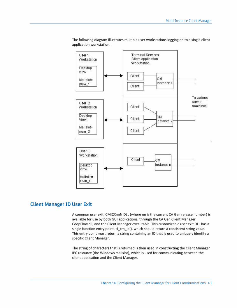
A Multi-Instance Client Manager operates similar to a single instance Client Manager with the only difference being that it is intended to operate in a multi-user environment. CA Gen supports Microsoft Windows Terminal Services. This multi-user execution environment provides a thin-client product allowing one or more "user workstations" to share client application resources residing on a single, shared Windows "client workstation." Each logged on "user workstation" is presented with its own, private desktop view executing upon the "client workstation."
The user workstation does not execute any portion of the CA Gen Distributed Processing application. The host client workstation executes the DPC portion of the application as well as the Client Manager instance.
The installed version of Client Manager operates with the expectation that it is being executed in a single user environment. Each user within a multi-user environment must have a unique instance of the Client Manager. To accomplish this, the installed Client Manager delivers a user exit that allows more than one instance of the Client Manager to execute in a multi-user environment. The Client Manager ID user exit (the ci_cm_id entry point) can be modified such that one instance of a Client Manager can be distinguished from another. Typically, customization of the user exit involves making use of a logon user-id or session-id that is unique for a given thin-client user.
Once the Client Manager ID user exit has been customized, each instance of the multi-instance Client Manager behaves the same as the single-instance version.
The modified Client Manager ID user exit resides in its own DLL (CMICXnnN.dll, where "nn" is the CA Gen release number). This DLL is used by the Client Manager and the Client Manager CoopFlow. The Client Manager CoopFlow is the code that supports the inter-process communications between the GUI applications and the Client Manager.
The technique used in the Client Manager ID user exit must, for each user, provide the same unique ID value when executing from an instance of the Client Manager and when executing from instances of a GUI application client. Providing the same Client Manager ID value allows a user's GUI applications to communicate with the unique instance of the Client Manager.
Note: For more information about user exits, see the User Exit Reference Guide.
More information:
Configuring the Client Manager for Client Communications (see page 41)

Client Manager Features
22 Distributed Processing - Client Manager User Guide
Client Manager Features
The Client Manager is a CA Gen application that resides on the client workstation to provide communications support for distributed processing GUI applications residing on that same client workstation. The overall purpose of the architecture of the Client Manager is to isolate communication configuration from the application design and implementation process. The Client Manager accepts message requests from the clients and forwards them to a target server environment. Server response data is routed back to the client that made the request.
Note: A Client Manager can only be used with GUI DPC applications created with CA Gen and generated targeting the communication environment type of "Gen."
Client Manager includes the following features and capabilities:
■ User-configurable
Modifying the Client Manager configuration can be accomplished in one of two ways:
– Using the Client Manager GUI interface (the preferred technique)
– Using an ASCII editor to modify the configuration text files
■ Ability to connect directly to the target server execution environment without requiring the optional CA Gen Communications Bridge (Comm. Bridge)
■ Supports requests from multiple DPC applications executing on the same workstation with the Client Manager
■ Supports concurrent communication sessions to one or more server platforms without requiring you to disconnect and reestablish connections to the desired target server
■ Supports concurrent multiple target server communications protocols/API
See Client and Server Connections in this chapter for a comprehensive list of supported target server protocols.
■ Optionally routes client cooperative flow requests using its Directory Services user exit to direct the requests to the appropriate, programmatically determined, target server
■ Optionally manages server access security:
– Saves server connection logon User Id and Password to configuration files, encrypting the saved password.
– Supports the use of enhanced security data if set by the DPC application Client side security user exit (WRSECTOKEN).
– Makes use of encrypted enhanced security data if encrypted by the DPC application Client encryption user exit (WRSECENCRYPT).
Client and Server Connections
Chapter 2: Client Manager Overview 23
■ Dynamically changes certain aspects of its configuration and the target servers' configurations without requiring you to stop and restart the Client Manager
■ Can be configured to automatically connect to a predefined default server upon startup
■ Allows support for multi-instance execution through a Client Manager User Exit when operating in a Microsoft Terminal Services environment
■ Can write selectable amounts of trace data to the Client Manager log file to assist in problem determination
■ Internal gathering and logging of transmission statistics
■ Selectable ASCII file browser for viewing Client Manager configuration and log files
■ A Client Manager can be installed separate from other CA products. For example, the Client Manager does not require the presence of the CA Gen Toolset to execute.
Client and Server Connections
This section discusses how communication data is routed to the Client Manager and the target server environment.
Client Communications
Communicating from a CA Gen DPC to the Client Manager is accomplished using Windows Inter-Process Communications (IPC) mechanisms known as mailslots and shared memory. When operating as the default single-instance Client Manager, the details of the IPC are internal to the CA Gen infrastructure and do not require any user configuration. When operating a multi-instance Client Manager, the IPC mechanism between a GUI application client and the Client Manager is influenced by the Client Manager ID user exit, ci_cm_id().
More information:
Configuring the Client Manager for Client Communications (see page 41)
Server Communications
The cooperative flow data can be transmitted either to the target server environment through a CA Gen Communication Bridge or directly to a target server environment. The transmission protocol used depends on the server's configuration and the target server selected by transaction routing.

Client and Server Connections
24 Distributed Processing - Client Manager User Guide
The following transport types are currently supported by the Client Manager:
LU6.2 (CPI-C)
Support for communications from Client Manager to:
■ z/OS CICS using LU 6.2(CPI-C)
■ z/OS IMS using LU 6.2(CPI-C)
TCP/IP (Sockets)
Support for communications from Client Manager to:
■ z/OS CICS using CICS TCP/IP Direct Connect
■ z/OS CICS using CICS Socket Listener (IPv4 or IPv6 protocol)
■ z/OS IMS using IMS TCP/IP Direct Connect (IPv4 or IPv6 protocol)
■ UNIX using Transaction Enabler environments (AEFUF/AEFAD) (IPv4 or IPv6 protocol)
■ UNIX using TUXEDO Proxy Client target server environment (IPv4 or IPv6 protocol)
■ Windows using Transaction Enabler environments (AEFUF/AEFAD) (IPv4 or IPv6 protocol)
■ Windows using Communications Bridge (IPv4 or IPv6 protocol)
■ Enterprise Java Bean CFB Converter Services (IPv4 or IPv6 protocol)
RSC/MP (NonStop Remote Server Call)
Support for communications from Client Manager to:
■ NonStop RSC/MP
Client Manager Transaction Routing
Chapter 2: Client Manager Overview 25
Other APIs
The Client Manager provides a transport selection that allows the specification of transports other than those listed in server transport API selection dialog. This selection should only be used under the guidance of Technical Support.
More information:
Configuring the Client Manager for Client Communications (see page 41)
Client Manager Transaction Routing
Cooperative flow requests initiated by a DPC application and serviced by the Client Manager are routed to the desired target server execution environment using a process known as "transaction routing."
Transaction routing is a facility that allows the execution environment hosting the target DPS to be determined programmatically during the Client Manager's processing of a client application cooperative flow request.
This feature could be used to:
■ Achieve dynamic load balance to multiple target server environments
■ Access a backup server environment should the primary environment be unavailable
■ Access multiple servers from a single client
The Client Manager implements and supports transaction routing using the user exit and data explained in the following section.
Client Manager Transaction Routing
26 Distributed Processing - Client Manager User Guide
Directory Services User Exit
Directory Services is a user exit DLL of the Client Manager that can optionally contain transaction routing routines. The user-written code can determine where a given cooperative flow request should be routed. The Directory Services user exit may use the following input arguments to determine its selection of the desired target server:
■ Transaction Code
The transaction code is a character string assigned to the remote procedure step and is associated with a transaction request.
■ NEXTLOCATION
NEXTLOCATION is a character string that contains the value defined to the NEXTLOCATION model attribute. The NEXTLOCATION attribute is defined and set in the CA Gen Procedure Action Diagram (PrAD) and can be used in conjunction with the Transaction code to determine which of the configured target servers is to process the cooperative flow request.
The default Directory Services user exit DLL, as installed from the CA Gen download folder, is to disable the use of Directory Services. Therefore, if customers want to employ the use of the Directory User exit, they must code and rebuild the Directory Services user exit DLL.
Note: For more information about user exits, see the User Exit Reference Guide.
More information:
User Exits (see page 109) Transaction Routing (see page 67)
Default Server
The Default Server configuration, set within the Client Manager, identifies the target server that is sent the cooperative flow request if dynamic routing is not implemented.
More information:
General Configuration (see page 31) Transaction Routing (see page 67)

Security
Chapter 2: Client Manager Overview 27
Security
The Client Manager does not perform any security validation of its own. Rather the Client Manager provides various mechanisms for providing the security data that will be used by the underlying transport mechanisms or by the target server execution environment to validate a given user request.
After the selection of a target server is determined, the Security Level associated with the target server is determined. The Security Level indicates whether the target server expects to receive cooperative flow requests that contain security data. A target server that has a derived Security Level of "Remote" causes the Client Manager to provide security data in the form of a UserID and Password to the transport processing the cooperative flow request.
If the Client Manager needs to provide security data, the Client Manager retrieves the security data in the following manner:
■ If the CFB received from the DPC contains a security offset and the WRSECTOKEN Client Security user exit indicated that the Client Manager should use the data (bClntMgrSecurity flag set to TRUE), then the UserID and Password are obtained from the CFB Security Offset area.
Note: If the CFB has been encrypted by the GUI runtime, the CFB must be decrypted by the Client Manager prior to obtaining the security data from the Security Offset area. (Decryption is performed by the Client Manager DECREXIT user exit.)
■ If the CFB does not contain a security offset area, or the CFB does not contain an indication that the security data in the security offset area should be used (bClntMgrSecurity flag set to FALSE), then the UserID and Password are obtained from the Client Manager configuration data.
Note: For more information about user exits, see the User Exit Reference Guide.
More information:
Server Access Security Using User ID and Password (see page 77)
Confirming DPC/DPS Communications
Note: Testing the Client Manager (see page 95) provides information that can be used to confirm proper client-to-server communications.

Confirming DPC/DPS Communications
28 Distributed Processing - Client Manager User Guide
Transaction Statistics
Certain statistics concerning byte transfers are gathered automatically. From the main GUI window of Client Manager, you can display a dialog containing a summary of the Client Manager statistics. Once displayed, the statistics dialog can be refreshed on demand or continuously refreshed based on a configurable time period.
More information:
Client Manager Server Flow Statistics (see page 105)
Customizable User Exits
The Client Manager contains user exits that can modify certain default behaviors.
Note: For more information about user exits, see the User Exit Reference Guide.
More information:
User Exits (see page 109)
Default Configuration and Log file Locations
Beginning with the Release 8 of CA Gen the default locations of the configuration and log files has changed. In prior releases the default locations for these files has been in the CA Gen installation directory.
To allow support of the User Account Control (UAC) mechanism featured with the Windows 7 operating systems this default location has been changed. With UAC enabled a non administrative user is not allowed to write into the Program Files subdirectory. As this is the recommended default Client Manager installation directory these user writeable files have been moved into the %USERPROFILE%\AppData\Local directory.
This is a per user directory location. Thus if multiple users have Client Manager execution authority each user will maintain separate configuration and log file locations.
The locations of these files can be overridden through configuration changes with the Files – Setup dialog accessible from the Client Manager main window.
Confirming DPC/DPS Communications
Chapter 2: Client Manager Overview 29
The default location for these configuration files will be as follows:
For the .ini and .srv configuration files:
%USERPROFILE%\AppData\Local\CA\Gen xx\cfg\cm
For the .log file:
%USERPROFILE%\AppData\Local\CA\Gen xx\logs\cm
For the transaction mapping file used when the server configuration is set to support RSC/MP:
%USERPROFILE%\AppData\Local\CA\Gen xx\cfg\cm\RSCMP\<Path-Mon>\tirtmt.tbl
where <Path-Mon> is the RSC/MP configured Pathway Monitor configuration setting.
Note: xx refers to the current release of CA Gen. For the current release number, see the Release Notes.
The default file names have not changed, only the default directory locations.

Chapter 3: General Configuration 31
Chapter 3: General Configuration
This chapter discusses miscellaneous topics required for installing and configuring a Client Manager. Included are:
■ Installation of a Client Manager
■ Customization of a Client Manager during first startup after install
■ Execution startup methods
■ Details of all configuration items found on the Client Manager File – Setup dialog
Client Manager Installation
The Client Manager is installed using the CA Gen product install procedure.
Note: For more information, see the Distributed Systems Installation Guide.
The Client Manager has no dependency on any other CA Gen product, so it can be installed separately.
First Start of Client Manager After Install
During the first Client Manager execution after installation, a dialog prompting for two configuration settings appears. This dialog allows the user to:
■ Choose the supported language to be used when displaying text for information and error messages. The default language is U.S. English.
■ Specify if the Userid and Password security data should be stored in the Client Manager's configuration files (iefcmn.ini and iefcmn.srv). If the security data is to be stored, the Password field is saved to the files in an encrypted format.
The Client Manager has two files that specify its configuration:
■ iefcmn.ini
■ iefcmn.srv
If the iefcmn.ini configuration file does not exist during the first startup after installation or if it does exist but does not contain an expected token, you are prompted with a choice for executing the Setup dialog. If you choose to run setup, then the File – Setup dialog is displayed giving you the opportunity to proceed with configuring the Client Manager.
Starting the Client Manager
32 Distributed Processing - Client Manager User Guide
If you decline the prompt or the file already exists, the Client Manager automatically exits after the Client Manager Customization dialog has been dismissed. This is necessary so that any designated configuration setting can be incorporated into the execution of the Client Manager. Subsequent executions will not require this first start configuration step.
Starting the Client Manager
There are three ways in which a Client Manager can be started:
■ Using the Windows Start menu
■ Using a desktop shortcut icon
■ From a command prompt
Desktop Start Menu
To start a Client Manager from the Windows Desktop start menu select Start, All Programs, CA, Gen <version>, Client Manager.
where, <version> is the CA Gen product version installed on your system.
Desktop Shortcut Icon
A Client Manager can be started from a desktop shortcut after the icon is created.
Create a Client Manager Shortcut
Follow these steps:
1. Right-click an empty area of the desktop.
2. Click New, Shortcut.
3. In the Create Shortcut dialog, click Browse.
4. Using the Browse for Folder dialog, select down the folder tree into the Client Manager installation directory.
5. Click the Client Manager executable file IEFCMxxN.EXE
Note: xx refers to the current release of CA Gen. For the current release number, see the Release Notes.
6. Click OK.
7. Click Next.
Starting the Client Manager
Chapter 3: General Configuration 33
8. Change the name of the shortcut if desired, and click Finish.
This creates a shortcut and place an icon on the desktop.
9. Locate the icon, right-click the icon, and select the Properties menu item.
10. In the edit field labeled Target, append to the file name the following parameters:
iefcm startup /initfile=iefcmn.ini
iefcm
Specifies the transaction code associated with the initial procedure step. This is a required parameter
startup
Specifies the initial command executed by the initial procedure step. This is a required parameter
/initfile=
Is followed by the name of the initialization file for this Client Manager instance. Use the filename iefcmn.ini for the first execution. In later executions, use the name you give the initialization file during configuration. This parameter is optional. If not specified, the default initialization file name "iefcmn.ini" is used.
For single-instance Client Manager it is not necessary to change the name of the iefcmn.ini as there would be a need for only one .ini file. For use in a multi-user environment, each instance of the Multi-Instance Client Manager must have its own uniquely named initialization file.
11. Click OK on the properties dialog to complete the shortcut configuration.
Using the Client Manager Shortcut
After you have created the shortcut on the workstation desktop, the Client Manager can be started by double-clicking on the shortcut icon.
Command Prompt
To start the Client Manager from a command prompt, change to the directory where the Client Manager is installed and enter the startup command as follows:
IEFCMxxN.exe iefcm startup /initfile=[filename]
Note: xx refers to the current release of CA Gen. For the current release number, see the Release Notes.
Client Manager Setup Dialog
34 Distributed Processing - Client Manager User Guide
IEFCMxxN.exe
Specifies the name of the Client Manager executable
iefcm
Specifies the transaction code associated with the initial procedure step. This is a required parameter.
startup
Specifies the initial command executed by the initial procedure step. This is a required parameter.
/initfile=
Is followed by the name of the initialization file for this Client Manager instance. Use the filename iefcmn.ini for the first execution. In later executions you will use the name you give the initialization file during configuration. This parameter is optional. If not specified, the default initialization file name "iefcmn.ini"is used.
For single-instance Client Manager it is not necessary to change the name of the iefcmn.ini as there would be a need for only one .ini file. For use in a multi-user environment, each instance of the Multi-Instance Client Manager must have its own uniquely named initialization file.
Client Manager Setup Dialog
This section covers those configurable items found on the Client Manager File – Setup dialog. While some items are discussed elsewhere within this document, this section is intended to provide the details about the Setup parameters in one central location.
Client Manager Setup Dialog
Chapter 3: General Configuration 35
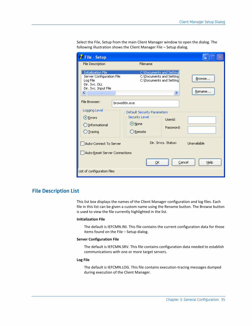
Select the File, Setup from the main Client Manager window to open the dialog. The following illustration shows the Client Manager File – Setup dialog.
File Description List
This list box displays the names of the Client Manager configuration and log files. Each file in this list can be given a custom name using the Rename button. The Browse button is used to view the file currently highlighted in the list.
Initialization File
The default is IEFCMN.INI. This file contains the current configuration data for those items found on the File – Setup dialog.
Server Configuration File
The default is IEFCMN.SRV. This file contains configuration data needed to establish communications with one or more target servers.
Log File
The default is IEFCMN.LOG. This file contains execution-tracing messages dumped during execution of the Client Manager.

Client Manager Setup Dialog
36 Distributed Processing - Client Manager User Guide
Dir. Svc. DLL
There is no default file name provided. If specified, this item names the DLL that provides Directory Services User Exit routines.
Dir. Svc. Input File
There is no default file name provided. If specified, this Directory Services User Exit file contains input transaction code and server name mappings used with the Directory Services User Exit routines.
More information:
User Exits (see page 109)
Browse Button
When you select a row from the File Description list and click Browse, the file browse utility, in the File Browser field on this dialog, displays the selected file.
Rename Button
When you select a row from the File Description list and click Rename, the Client Manager displays the Setup – Change Filename dialog. This dialog allows the user to customize the name of the selected file.
File Browser
A text entry field used to specify the name of the utility program used to view text files. Any viewer capable of reading text files can be used. The full pathname of the file viewer must be used if it is not found within the execution environment's PATH variable.
Client Manager Setup Dialog
Chapter 3: General Configuration 37
Logging Level
Three radio buttons control the level of information that is output to the trace log file:
Errors
Select the Errors radio button for normal operations. Only information pertaining to error events is logged to the log file.
Informational
Select the Informational radio button if you want to see error events and informational messages concerning cooperative flow request and responses.
Tracing
Select the Tracing radio button if you are attempting to diagnose a communications error. This setting shows all of the error events, informational messages, and message buffer data. This setting can create rather large log files.
Default Security Parameters
The security parameters provided as part of the Client Manager Setup specify the definition of a default security level, Userid and Password. Individual target server definitions can defer the specification of security level to the Client Manager default setting. Additionally, the default Userid and Password can be used if the selected target server configuration does not specifically define a Userid and Password.
Note: For more information about how the Client Manager resolves the selection of security data for a cooperative flow targeting a given target server, see the chapter Server Access Security using Userid and Password (see page 77).
Security Level
The security levels are:
■ None—The selected target server does not require the Client Manager to provide a Userid and Password.
■ Remote—The selected target server requires the Client Manager to provide a Userid and Password.
Userid
Userid specifies up to an 8-character default Userid. The default Userid is used if the security level associated with the target server is Remote and the Userid is not explicitly defined as part of the target server configuration.
Important! If requested to save the Userid and Password to the configuration files, the Userid is saved in clear text in the initialization file.

Client Manager Setup Dialog
38 Distributed Processing - Client Manager User Guide
The ability to allow the Client Manager to save the Userid and Password may be disabled during the first start of the Client Manager after installation customization process. If enabled, and you want to save the Userid and Password to the server configuration file (.SRV), you must select the Save Userid and Password check box on the Client Manager File – Save Configuration dialog. The saved Password is encrypted.
More information:
Saving Configuration Files (see page 91)
Password
You can specify up to eight characters for the default Password. The default Password is used if the security level associated with the target server is Remote and the Password is not explicitly defined as part of the target server configuration.
Important! The encrypted default Password can optionally be saved to the initialization file.
The ability to allow the Client Manager to save the Userid and Password may be disabled during the first start of the Client Manager after installation customization process. If enabled, and you want to save the Userid and Password to the server configuration file (.SRV), you must select the Save Userid and Password check box on the Client Manager File – Save Configuration dialog. The saved Password is encrypted.
More information:
Saving Configuration Files (see page 91)
Dir. Srvcs. Status
This read-only status field shows the current state of the directory services capability. A status of "Unavailable" means the Client Manager Directory Service has not been enabled for this Client Manager. A status of "Available" means the Directory Service is enabled for this Client Manager.
More information:
Transaction Routing (see page 67)
Client Manager Setup Dialog
Chapter 3: General Configuration 39
Auto-Connect to Server
Checking this check box directs the Client Manager at startup to establish an automatic connection to the identified default target server. Also, selecting this check box results in an automatic flow when performing a logon operation to a selected target server.
For automatic connections to work at startup the:
■ Client Manager default server must be defined
■ Test transaction must be defined
■ Auto-Connect to Server check box must be selected
For automatic connections to work when performing a logon the:
■ Test transaction must be defined
■ Auto-Connect to Server check box must be selected.
Auto-Reset Server Connection
The Auto-Reset Server Connection check box, if checked, allows an automatic disable followed by enable of the server connection after an existing server configuration is modified.
Disabling a server:
■ Disconnects the server connection
■ Removes all data pertaining to that connection
■ Makes the server unavailable for use
Enabling a server makes the server available for use.
If the Auto-Reset Server Connection check box is not checked, the server connection must be manually reset before any server configuration modifications take effect.

Chapter 4: Configuring the Client Manager for Client Communications 41
Chapter 4: Configuring the Client Manager for Client Communications
With the advent of various thin-client product offerings, such as Microsoft Terminal Server with NT 5.0, multiple users (or "thin clients") can share application program resources that reside on a single, shared, Windows client workstation. The thin client logs on to the Windows client workstation.
In the traditional, single-user Windows workstation environment, only one desktop view is active. The view that is displayed is that of the user currently logged on to the physical workstation. Communicating from a Distributed Processing Client (DPC) to the Client Manager takes place using the Windows IPC mailslot API. This API uses a well-known mailslot identifier to connect an application executing on the workstation with its active Client Manager.
Within a multi-user server environment, multiple thin client users operating on separate physical user workstations, logon to a single client application workstation. Each user workstation has its own unique desktop view of the shared client application workstation. Each user's desktop view is displayed to their respective user workstations by way of it executing the thin client software. Communicating from a given DPC applications to their specific instance of the Client Manager takes place using the Windows IPC mailslot API. The well known, unique mailslot identifier is used to connect a user's distinct applications to their unique instance of the Client Manager.
In multi-user environments, it is necessary that each user have their own instance of the Client Manager. In this, case a user's Client Manager instance and their associated DPC applications make use of the same mailslot identifier.
Single-Instance Client Manager
The single-instance Client Manager is how the Client Manager is installed from the CA Gen download folder. The ability to execute multi-instance Client Manager is accomplished by modifying the Client Manager ID User Exit (cicmclx.c). This file must be modified to return a unique ID value for each distinct user connecting to the multi-user client workstation.
Multi-Instance Client Manager
42 Distributed Processing - Client Manager User Guide
Multi-Instance Client Manager
In a multi-instance environment, there must be multiple instances of Client Manager active on the same shared client workstation. The unique mailslot identifier as specified by the Client Manager CoopFlow runtime can determine the user who has logged on to the Client Manager. The Client Manager CoopFlow Runtime and the Client Manager share the same DLL containing the Client Manager ID user exit. The Client Manager uses the user exit during the initialization processing that constructs the mailslot name. The GUI Runtime makes use of the Client Manager CoopFlow when it processes a cooperative flow to the Client Manager.
System resource conflicts occur if more that one instance of the Client Manager attempts to use the same mailslot identifier. Only the first instance of the Client Manager would be able to allocate the mailslot. Other instances of the Client Manager fail due to the mailslot conflicts.
To support a multi-instance environment, each Client Manager must provide a unique ID. This unique ID is used when constructing its mailslot identifier. The unique id is obtained using the Client Manager ID user exit. The ci_cm_id() entry point is located in the cicmclx.c source file. The user-written code typically would make use of the unique logon user-id, session-id, or some other attribute that uniquely distinguishes one user of a multi-user environment from another.
Each occurrence of a Multi-Instance Client Manager behaves the same as its single-instance counterpart. Each occurrence of a Multi-Instance Client Manager must have its own initialization (.ini) and log file, but if desired, they can share the server configuration (.srv) file. However, sharing the .srv file limits their ability for each user to maintain separate security data for individual target server definitions. Therefore, it is recommended that each user have individual server configuration files as well.
There is never more than one Client Manager GUI interface displayed within a single desktop view. Attempting to start a second instance within the same desktop view, results in the currently active Client Manager instance being given desktop view focus.
Multi-Instance Client Manager
Chapter 4: Configuring the Client Manager for Client Communications 43
The following diagram illustrates multiple user workstations logging on to a single client application workstation.
Client Manager ID User Exit
A common user exit, CMICXnnN.DLL (where nn is the current CA Gen release number) is available for use by both GUI applications, through the CA Gen Client Manager CoopFlow dll, and the Client Manager executable. This customizable user exit DLL has a single function entry point, ci_cm_id(), which should return a consistent string value. This entry point must return a string containing an ID that is used to uniquely identify a specific Client Manager.
The string of characters that is returned is then used in constructing the Client Manager IPC resource (the Windows mailslot), which is used for communicating between the client application and the Client Manager.
Multi-Instance Client Manager
44 Distributed Processing - Client Manager User Guide
Example:
■ For a Windows workstation running in single-instance Client Manager, the default exit implementation is sufficient to identify the Client Manager. The current default mailslot name used is .\mailslot\TIRCLNTS.QUE. In this instance, the string returned from the exit is TIRCLNTS.
■ For workstations that need to support multiple logged on users, a unique ID must be used (for example: a USERNAME environment variable) to differentiate one execution of one Client Manager from another. For example, if the USERNAME variable is John Doe, then the string returned by the user exit to the Client Manager would be John_Doe. The string John_Doe is then used to derive a mailslot name of \mailslot\John_Doe.QUE. The same mailslot naming scheme will be used by all clients connecting to this instance of a Client Manager.
Notes:
■ The returned string from ci_cm_id() must be 64 characters or less. A returned string longer than 64 characters is truncated at 64. The returned string cannot contain any blanks.
■ For further information regarding implementing this user exit, see the User Exit Reference Guide.
More information:
User Exits (see page 109)

Chapter 5: Configuring Client Manager Server Connections 45
Chapter 5: Configuring Client Manager Server Connections
The Client Manager has the capability of communicating with CA Gen server environments using several supported communications protocols. The purpose of the server execution environment is to accept cooperative flow data from clients and pass the data to the appropriate target server.
This chapter provides the information needed for configuring the Client Manager to communicate with the various target server execution environments.
This section contains the following topics:
Server Configuration (see page 46) Transport API – Additional Details (see page 48)
Server Configuration
46 Distributed Processing - Client Manager User Guide
Server Configuration
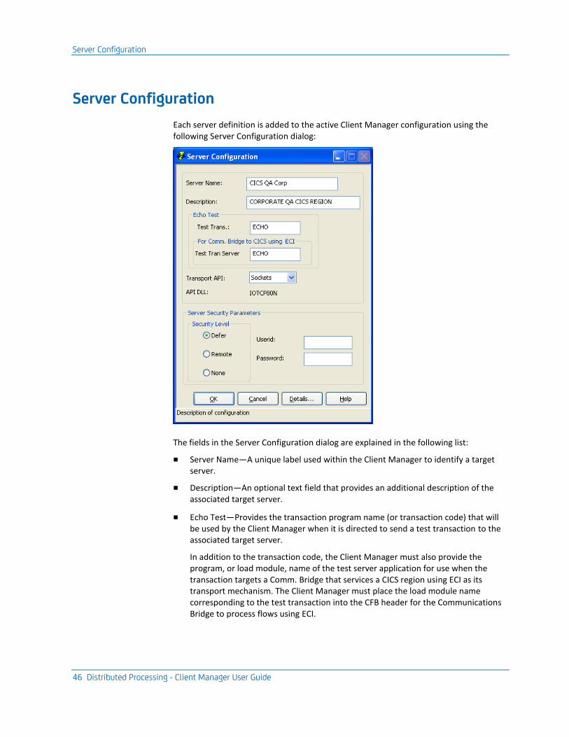
Each server definition is added to the active Client Manager configuration using the following Server Configuration dialog:
The fields in the Server Configuration dialog are explained in the following list:
■ Server Name—A unique label used within the Client Manager to identify a target server.
■ Description—An optional text field that provides an additional description of the associated target server.
■ Echo Test—Provides the transaction program name (or transaction code) that will be used by the Client Manager when it is directed to send a test transaction to the associated target server.
In addition to the transaction code, the Client Manager must also provide the program, or load module, name of the test server application for use when the transaction targets a Comm. Bridge that services a CICS region using ECI as its transport mechanism. The Client Manager must place the load module name corresponding to the test transaction into the CFB header for the Communications Bridge to process flows using ECI.
Server Configuration
Chapter 5: Configuring Client Manager Server Connections 47
■ Transport API—The transport API designates which communications protocol is used to communicate with the associated target server execution environment. The Client Manager supports the following transport/protocols:
– LU6.2 (CPI-C)
■ z/OS CICS
■ z/OS IMS
– TCP/IP (Sockets)
■ UNIX: CA Gen Transaction Enabler (User Funnel)
■ UNIX: CA Gen Tuxedo Proxy Client
■ Windows: CA Gen Transaction Enabler (User Funnel)
■ Windows: CA Gen Communications Bridge
■ Windows CA Gen Enterprise Java Bean Common Format Buffer Converter Services
■ z/OS CICS Socket Listener
■ z/OS CICS: TCP/IP Direct Connect
■ z/OS IMS: IMS TCP/IP Direct Connect
– RSC/MP (Remote Server Call)
■ NonStop/MP
■ Server Security Parameters—Each configured server has a set of security parameters associated with it. These security parameters include a Security Level, UserID, and Password.
The three security levels, None, Remote, and Defer, inform the Client Manager about whether it should attempt to supply security data when attempting to process a cooperative flow request to the target server.
The user id and password are the security credentials that are used by the distributed processing server processes to grant execution access.
More information:
Testing the Client Manager (see page 95) Server Access Security Using User ID and Password (see page 77)
Transport API – Additional Details
48 Distributed Processing - Client Manager User Guide
Transport API – Additional Details
The Client Manager can use one of three provided transport protocols when communicating with a target server execution environment, LU 6.2, TCP/IP or RSC/MP. In the case of TCP/IP, the Client Manager can define the target server to be a CA Gen Comm Bridge. In this case, the Comm Bridge provides the communications interface to the actual target server.
The following sections describe the configuration details of these connections:
■ LU 6.2 CPI-C Connections
■ TCP/IP Socket Connections
■ NonStop RSC/MP Connections
■ Other
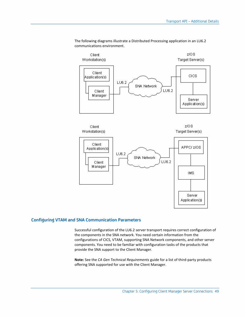
LU 6.2 CPI-C Connections
Cooperative flows from a client application can pass through a Client Manager and then on to a CICS or IMS target server environment using an SNA Independent LU (ILU).
Each cooperative flow results in an LU6.2 conversation being established between the Client Manager and the target server environment (CICS or IMS). Each cooperative flow request Common Format Buffer (CFB) is transmitted over its own LU 6.2 conversation. The conversation is completed when a corresponding response is returned to the Client Manager.
Transport API – Additional Details
Chapter 5: Configuring Client Manager Server Connections 49
The following diagrams illustrate a Distributed Processing application in an LU6.2 communications environment.
Configuring VTAM and SNA Communication Parameters
Successful configuration of the LU6.2 server transport requires correct configuration of the components in the SNA network. You need certain information from the configurations of CICS, VTAM, supporting SNA Network components, and other server components. You need to be familiar with configuration tasks of the products that provide the SNA support to the Client Manager.
Note: See the CA Gen Technical Requirements guide for a list of third-party products offering SNA supported for use with the Client Manager.
Transport API – Additional Details
50 Distributed Processing - Client Manager User Guide
To establish communications between the Client Manager and the target server, you need to obtain parameters related to the z/OS SNA environment. For a z/OS CICS target server, these parameters are found in the VTAM and NCP configurations. This includes:
■ VTAM Application LU name of the CICS region
■ SNA independent LU name
■ VTAM Log Mode table entry of a logon mode entry that allows for parallel LU6.2 sessions
Specific instructions for setting VTAM, NCP, and CICS parameters can be found in your IBM documentation associated with the third-party SNA product.
Configuring the Client Workstation
Once the VTAM, NCP, CICS, and/or APPC z/OS configurations have been completed on the host, values from these configurations are used to configure a client workstation that supports LU6.2 communications to z/OS (CICS or IMS).
After the SNA product offering LU6.2 communications to the Client Manager is configured, a Client Manager can configure a target server that uses CPI-C as it transport API.
Configuring the Client Manager for LU6.2
When configuring a Client Manager to use CPI-C for a given target server, the following parameters from the LU6.2 network configuration are required:
■ Partner LU name of the application LU name for CICS or IMS
■ Local LU Alias - This field may or may not be used depending on the SNA service provider. Certain SNA providers allow an application to specify the Local LU Alias prior to allocating a conversation. Others select the LU based on their own defined convention. This field is ignored if the SNA service provider does not allow the Local LU Alias to be specified by the application program.
Note: For more information about how a Local LU is selected for use by a CPI-C application program, see the third-party vendor documentation.
■ Mode Table Entry name
■ Code Page number
Follow these steps:
1. Start the Client Manager and select Server, Config.
2. Enter a server name and description for this target server connection.
3. Select CPI-C from the Transport API selection list. The Client Manager automatically supplies the API DLL name.
4. Click Details to display the LU6.2 (CPI-C) Server Configuration – Details dialog.
Transport API – Additional Details
Chapter 5: Configuring Client Manager Server Connections 51
5. Provide the LU6.2 parameter values listed above.
6. Click More to display the Server Configuration – More Details dialog.
7. Select an appropriate code page for translation.
8. Click OK to return to the Server Configuration – Details dialog.
9. Click OK to return to the Server Configuration dialog.
10. Click OK to return to the main menu.
Save the current configuration.
More information:
Saving Configuration Files (see page 91)
TCP/IP Socket Connections
For TCP/IP server connections, you must set server configuration parameters within the Client Manager corresponding to the target server environments, which include the following:
■ UNIX CA Gen Transaction Enabler (User Funnel)
■ UNIX CA Gen Tuxedo Proxy Client
■ Windows CA Gen Transaction Enabler (User Funnel)
■ Windows CA Gen Communications Bridge
■ Windows CA Gen Enterprise Java Bean CFB Server
■ z/OS CICS Socket Listener
■ z/OS CICS TCP/IP Direct Connect
■ z/OS IMS TCP/IP Direct Connect
Client Manager to Server Configuration
The Client Manager TCP/IP implementation makes use of stream sockets. A stream socket provides a full-duplex, sequenced, reliable transmission mechanism over which a DPC cooperative flow request can be transmitted. The socket provides the TCP communications endpoint, used by the Client Manager, to gain access to the IP network.
A target server environment, which is connected to the IP network, listens for inbound connections and data transmissions using a socket that is located on the system hosting the target server.
Transport API – Additional Details
52 Distributed Processing - Client Manager User Guide
A socket, used by the Client Manager, consists of two parts, each defining application endpoints in the TCP communications. One of the application endpoints is the local application (that is, the Client Manager). The other endpoint is the socket processing that supports the given target server environment. These front-end connection management processes for a given server execution environment are as follows:
■ AEFUF for CA Gen Transaction Enabler
■ IEFTUXCL for Oracle Tuxedo
■ CA Gen Communication Bridge for CICS or IMS
■ CA Gen z/OS CISC Socket Listener for CICS
■ CA Gen z/OS CICS Direct Connect for CICS
■ CA Gen z/OS IMS Direct Connect for IMS
Each connection that a client TCP application establishes on a given workstation is identified by its unique TCP port address. When a connection to a target server is requested, the source port address is selected by TCP from those port numbers not already in use by other TCP connections currently established. The destination port address is the target server environment well-known port address. The target server IP address, along with its port address, is used by the Client Manager in the construction of the destination portion of the TCP socket.
Target Server Environment Communication Styles
The Client Manager supports 3 distinct styles of communications to target servers using the TCP/IP Sockets protocol. The three styles are configurable via check boxes on the Sockets Server Configuration – Details dialog. The state of the check boxes depends on the target server environment requirements.
All three use the same features of the underlying TCP/IP protocol. Two of the styles differ in the length of the life span of the connection, the third in how the Common Format Buffer (CFB) data is packaged.
Connection Life Time
Two different connection life time modes are supported. The mode chosen, persistent vs. non persistent, is dependent on the needs of the target server environment.
Persistent socket connections are those connections that are long lived. After a connection is established that same connection object is used for multiple client to server transactions. The connection is maintained until the client or server application performs a connection disconnect or exits. This type of connection is used by the Transaction Enabler (TE) on UNIX and Windows, z/OS IMS TCP/IP Direct Connect, z/OS CICS TCP/IP Direct Connect, EJB CFB Server, Windows Comm Bridge, and the Tuxedo Proxy Client on UNIX.
Transport API – Additional Details
Chapter 5: Configuring Client Manager Server Connections 53
Non persistent socket connections are maintained for the duration of a single client to server transaction. After the server returns a response buffer back to the client the server will close its connection. A subsequent client request to the same server requires that a new connection be established. This type of connection is supported only when connecting with the z/OS CICS Socket Listener.
Common Format Buffer Packaging
The third TCP/IP communication style concerns how the Common Format Buffer data is delivered to the target server. There are two choices, wrapped for IMS support or unwrapped.
Communications to z/OS IMS TCP/IP Direct Connect require the CFB to be wrapped inside of IMS header data prior to it being sent to the IMS target server environment. Only z/OS IMS Direct Connect has this requirement. All other TCP/IP target server environments require a normal or non wrapped CFB.
Configuring the Client Manager for TCP/IP (Sockets)
To configure a Client Manager to communicate with a TCP/IP server environment, you need:
■ The target server machine host name or its IP address
■ The target server configured/well-known port address (destination port number)
To relate the machine name of the target server environment to a network address, you can either modify the communication workstations hosts file or make use of a Domain Name Services (DNS).
To modify the hosts file or the DNS configuration on the client workstation, see the appropriate vendor documentation for instructions about using hosts file or DNS setup.

Transport API – Additional Details
54 Distributed Processing - Client Manager User Guide
To set the Client Manager configuration files for TCP/IP transport use:
Follow these steps:
1. Start the Client Manager and select Server, Config.
2. On the Server Configuration dialog, enter a server name and description for this target server connection.
3. If a test transaction is to be used to verify the server connection, verify the displayed Test Trans is correct. The default value is ECHO.
4. If the target server is a Comm Bridge and if that Comm Bridge is configured to use ECI for server communications, verify that the Test Tran Server value is correct. The default value is ECHO. This configuration item is used by a Comm Bridge when it uses ECI to communicate with a CICS target server execution environment.
5. Select Sockets from the Transport API selection list. The Client Manager automatically supplies the API DLL name.
6. Click Details to display the TCP/IP Server Configuration – Details dialog.
7. Provide the TCP/IP parameters that identify the target server environment.
8. Select one, if appropriate, of the socket connection style check boxes according to the target server environment requirements as listed below.
Target Server Environment CICS Socket Listener check box
IMS TCP/IP Direct Connect Host check Box
UNIX CA Gen Transaction Enabler (User Funnel)
Unchecked Unchecked
UNIX: CA GenTuxedo Proxy Client Unchecked Unchecked
Windows CA Gen Transaction Enabler (User Funnel)
Unchecked Unchecked
Windows CA Gen Communications Bridge
Unchecked Unchecked
Windows CA Gen Enterprise Java Bean CFB Server
Unchecked Unchecked
z/OS IMS TCP/IP Direct Connect Unchecked Checked
z/OS CICS Socket Listener Checked Unchecked
9. Click OK to return to the Server Configuration dialog.
10. Click OK in the Server Configuration dialog to return to the main window.
Save the current configuration.
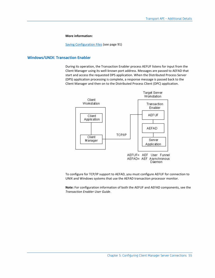
Transport API – Additional Details
Chapter 5: Configuring Client Manager Server Connections 55
More information:
Saving Configuration Files (see page 91)
Windows/UNIX: Transaction Enabler
During its operation, the Transaction Enabler process AEFUF listens for input from the Client Manager using its well-known port address. Messages are passed to AEFAD that start and access the requested DPS application. When the Distributed Process Server (DPS) application processing is complete, a response message is passed back to the Client Manager and then on to the Distributed Process Client (DPC) application.
To configure for TCP/IP support to AEFAD, you must configure AEFUF for connection to UNIX and Windows systems that use the AEFAD transaction processor monitor.
Note: For configuration information of both the AEFUF and AEFAD components, see the Transaction Enabler User Guide.

Transport API – Additional Details
56 Distributed Processing - Client Manager User Guide
UNIX: Tuxedo Proxy Client
Tuxedo-based servers can optionally use the CA Gen Tuxedo proxy client as a means to communicate with Tuxedo servers. The Tuxedo Proxy client listens for input from the Client Manager using its well-known port address. Messages are passed to Tuxedo that, in turn, start and access the requested DPS application. When the DPS application processing is complete, a response message is passed back to the Client Manager and on to the DPC application.
To configure TCP/IP support for Tuxedo, you must configure the CA Gen Tuxedo Proxy Client for connecting to UNIX servers that execute under the Tuxedo transaction processor monitor.
Note:
■ For Installation and configuration information for the CA Gen Tuxedo Proxy Client component, see the Tuxedo User Guide.
■ For information on configuring and starting Tuxedo, see your vendor documentation.

Transport API – Additional Details
Chapter 5: Configuring Client Manager Server Connections 57
Windows: CA Gen Communications Bridge
The Communications Bridge (Comm Bridge) provides communications support by serving as a gateway between the Client Manager and target server environments. The Client Manager passes request message data to the Comm Bridge using TCP/IP (Sockets). The Comm Bridge passes the message data on to the target server environment using one of the supported server side protocols:
■ LU 6.2 (CPI-C) to z/OS (CICS or IMS)
■ TCP/IP (Sockets) to
– z/OS (CICS or IMS)
– Windows (Transaction Enabler)
– UNIX (Transaction Enabler or Tuxedo)
■ z/OS CICS External Call Interface (ECI).
■ NonStop RSC/MP
When the DPS application processing is complete, a response message is passed back to the Comm. Bridge, then on to the Client Manager and finally on to the DPC application.
Note: Installation and configuration information for the Communication Bridge can be found in the Distributed Processing – Communication Bridge User Guide.
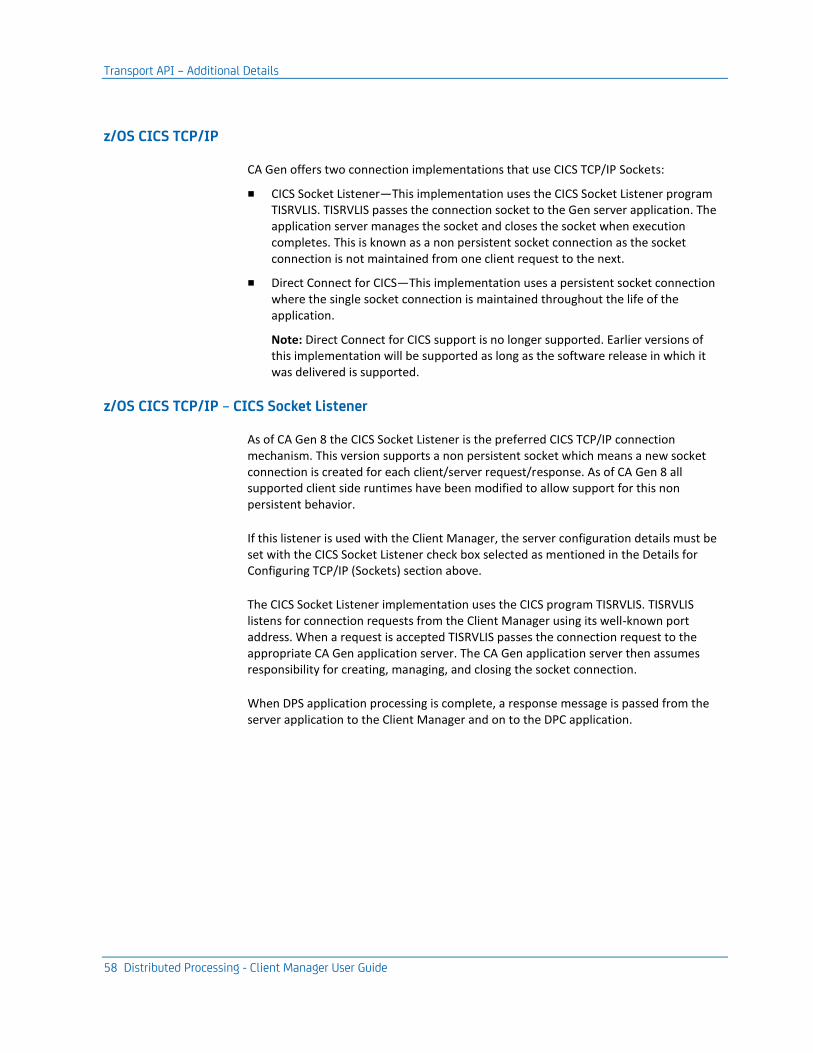
Transport API – Additional Details
58 Distributed Processing - Client Manager User Guide
z/OS CICS TCP/IP
CA Gen offers two connection implementations that use CICS TCP/IP Sockets:
■ CICS Socket Listener—This implementation uses the CICS Socket Listener program TISRVLIS. TISRVLIS passes the connection socket to the Gen server application. The application server manages the socket and closes the socket when execution completes. This is known as a non persistent socket connection as the socket connection is not maintained from one client request to the next.
■ Direct Connect for CICS—This implementation uses a persistent socket connection where the single socket connection is maintained throughout the life of the application.
Note: Direct Connect for CICS support is no longer supported. Earlier versions of this implementation will be supported as long as the software release in which it was delivered is supported.
z/OS CICS TCP/IP – CICS Socket Listener
As of CA Gen 8 the CICS Socket Listener is the preferred CICS TCP/IP connection mechanism. This version supports a non persistent socket which means a new socket connection is created for each client/server request/response. As of CA Gen 8 all supported client side runtimes have been modified to allow support for this non persistent behavior.
If this listener is used with the Client Manager, the server configuration details must be set with the CICS Socket Listener check box selected as mentioned in the Details for Configuring TCP/IP (Sockets) section above.
The CICS Socket Listener implementation uses the CICS program TISRVLIS. TISRVLIS listens for connection requests from the Client Manager using its well-known port address. When a request is accepted TISRVLIS passes the connection request to the appropriate CA Gen application server. The CA Gen application server then assumes responsibility for creating, managing, and closing the socket connection.
When DPS application processing is complete, a response message is passed from the server application to the Client Manager and on to the DPC application.
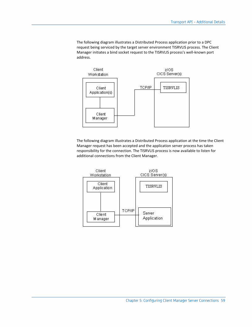
Transport API – Additional Details
Chapter 5: Configuring Client Manager Server Connections 59
The following diagram illustrates a Distributed Process application prior to a DPC request being serviced by the target server environment TISRVLIS process. The Client Manager initiates a bind socket request to the TISRVLIS process's well-known port address.
The following diagram illustrates a Distributed Process application at the time the Client Manager request has been accepted and the application server process has taken responsibility for the connection. The TISRVLIS process is now available to listen for additional connections from the Client Manager.

Transport API – Additional Details
60 Distributed Processing - Client Manager User Guide
The following diagram illustrates a Distributed Process application after the server application has completed. The socket connection used for the transaction has been closed. The TISRVLIS process is handling another connection request from the Client Manager and the cycle repeats.
Note: Installation and configuration information for the TISRVLIS component appears in the Host Encyclopedia and Host Construction Installation Guide and in the z/OS Implementation Toolset Installation Guide.
z/OS CICS TCP/IP Direct Connect
Note: This implementation of CICS TCP/IP Direct Connect support using TILSTNR and TICONMGR is no longer supported. Earlier versions of this implementation will be supported as long as the software release in which it was delivered is supported.
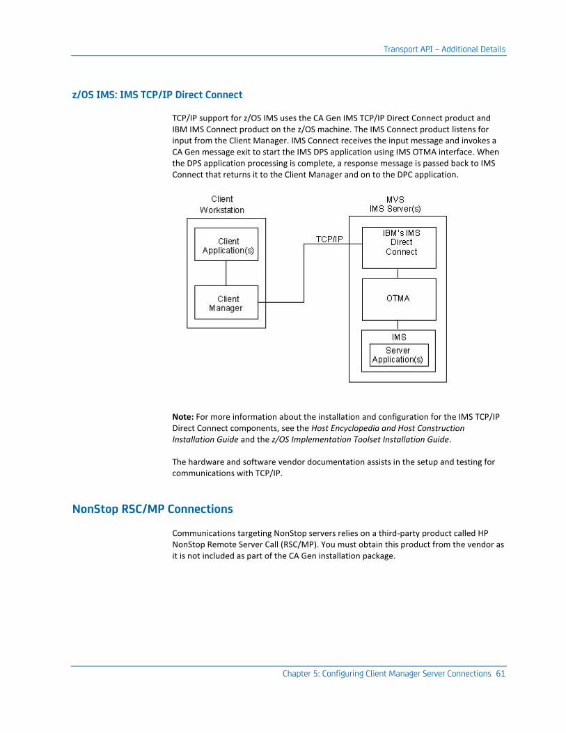
Transport API – Additional Details
Chapter 5: Configuring Client Manager Server Connections 61
z/OS IMS: IMS TCP/IP Direct Connect
TCP/IP support for z/OS IMS uses the CA Gen IMS TCP/IP Direct Connect product and IBM IMS Connect product on the z/OS machine. The IMS Connect product listens for input from the Client Manager. IMS Connect receives the input message and invokes a CA Gen message exit to start the IMS DPS application using IMS OTMA interface. When the DPS application processing is complete, a response message is passed back to IMS Connect that returns it to the Client Manager and on to the DPC application.
Note: For more information about the installation and configuration for the IMS TCP/IP Direct Connect components, see the Host Encyclopedia and Host Construction Installation Guide and the z/OS Implementation Toolset Installation Guide.
The hardware and software vendor documentation assists in the setup and testing for communications with TCP/IP.
NonStop RSC/MP Connections
Communications targeting NonStop servers relies on a third-party product called HP NonStop Remote Server Call (RSC/MP). You must obtain this product from the vendor as it is not included as part of the CA Gen installation package.

Transport API – Additional Details
62 Distributed Processing - Client Manager User Guide
Installing and Configuring RSC/MP
After you install RSC/MP, ensure the path to its /bin directory is included in the %PATH% environment variable. This is required as the Client Manager transport DLL depends on RSC/MP DLL's installed within the bin directory.
Note: For more information about installing and configuring RSC/MP, see the HP NonStop Remote Server Call (RSC/MP) Installation and Configuration Guide.
The following examples show how to customize the RSC/MP files for use within the CA Gen environment.
RSC.ini customization
A sample content from a typical %RSC_INSTALL_DIR%\bin\RSC.ini file is shown next. These configuration items should be merged within the existing RSC.ini file as this list is not all inclusive. The following example defines a new section called GEN_RSC, which is also the name used for the Client Manager Initialization Section Name configuration as shown next.
Note: Use [ ] when defining sections within the RSC.ini file.
[GEN_RSC]
;
; Set the fully qualified RSC/MP error file name.
; Assume RSC/MP is installed in C:\rsc
error_file = c:\rsc\bin\RSC.ERR
; The following options are required for Piccolo connections.
; set them to appropriate values.
; this is the default
subsystem_name = RSCPIPE ;( default = RSCPIPE )
; the host_pipename is typically the host name of the target NonStop
; machine. Replace SOME_NONSTOP_HOST with the target server name
host_pipename = RSC@SOME_NONSTOP_HOST
; The value of the writeread_pathmon entry should be that of the
; name of the Pathmon process for the CA Gen application that
; has or will be installed on the NonStop server. This name must
; match the name entered in the Setup Tool when the application was
; or will be installed.
writeread_pathmon = $TEST
Transport API – Additional Details
Chapter 5: Configuring Client Manager Server Connections 63
Note: RSC/MP test programs use the default [RSC] section within RSC.ini for testing client/server communications. This named entry must remain within the RSC.ini file if you want to successfully test the base RSC/MP installation. Some of values used in the RSC.ini file configuration rely on RSC/MP server side configuration settings. For more information about your RSC/MP installation at your site, contact your system administrator.
Pipe.ini customization
A sample content from a typical %RSC_INSTALL_DIR%\bin\PIPE.ini file is shown next. These configuration items should be merged within the existing PIPE.ini file as this list is not all inclusive. This data is used internally by RSC/MP.
[PIPEMAN]
; SystemName is the name of the client workstation where
; the RSC/MP client and Gen Client Manager is installed.
SystemName=Client_Workstation
; DomainName is the domain where the SystemName machine resides
DomainName=CA.COM
Note: For more information about configuration and basic communication testing, see the HP NonStop Remote Server Call (RSC/MP) Installation and Configuration Guide.
Verifying RSC/MP Communications
Communications between the Windows workstation and the NonStop server must be established. RSC/MP is not operational without a working transport. RSC/MP supplies a file, rsctestw.exe, which can be used to test the RSC/MP configuration on the workstation. Do not continue if you have not successfully executed this program.
Note: For more information about executing this program, see the HP Remote Server Call (RSC/MP) Installation and Management Guide.
Configure the Client Manager for NonStop RSC/MP
For NonStop RSC/MP server connections, you must set server configuration parameters within the Client Manager corresponding to the NonStop target server environment.
Note: Asynchronous flows, to a NonStop server are not supported through the Client Manager.
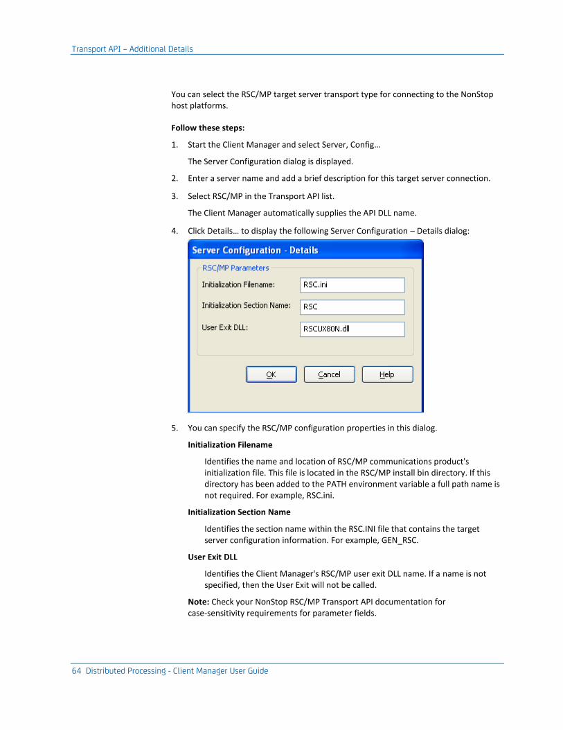
Transport API – Additional Details
64 Distributed Processing - Client Manager User Guide
You can select the RSC/MP target server transport type for connecting to the NonStop host platforms.
Follow these steps:
1. Start the Client Manager and select Server, Config…
The Server Configuration dialog is displayed.
2. Enter a server name and add a brief description for this target server connection.
3. Select RSC/MP in the Transport API list.
The Client Manager automatically supplies the API DLL name.
4. Click Details… to display the following Server Configuration – Details dialog:
5. You can specify the RSC/MP configuration properties in this dialog.
Initialization Filename
Identifies the name and location of RSC/MP communications product's initialization file. This file is located in the RSC/MP install bin directory. If this directory has been added to the PATH environment variable a full path name is not required. For example, RSC.ini.
Initialization Section Name
Identifies the section name within the RSC.INI file that contains the target server configuration information. For example, GEN_RSC.
User Exit DLL
Identifies the Client Manager's RSC/MP user exit DLL name. If a name is not specified, then the User Exit will not be called.
Note: Check your NonStop RSC/MP Transport API documentation for case-sensitivity requirements for parameter fields.
Transport API – Additional Details
Chapter 5: Configuring Client Manager Server Connections 65
6. Click OK to return to the Client Manager main window.
7. Save the configuration.
The Client Manager is now configured for NonStop RSC/MP.
More information:
Saving Configuration Files (see page 91)
Transaction Mapping Table
When connected to a server transaction mapping data is transferred from the host and is stored in a local file. This file is located in the following directory:
%USERPROFILE%\AppData\Local\CA\Gen xx\cfg\cm\RSCMP\<Path-Mon>\tirtmt.tbl
where %USERPROFILE% corresponds to the directory location the Windows operating system uses for the user id which is executing the Comm Bridge. <Path-Mon> corresponds to the name of the configured Pathway Monitor on the NonStop system. The content of the file is used internally by the Comm Bridge and should not be modified.
Note: xx refers to the current release of CA Gen. For the current release number, see the Release Notes.
Other API
The other API protocol is a server side transport that is intended for use under the guidance of Technical Support.

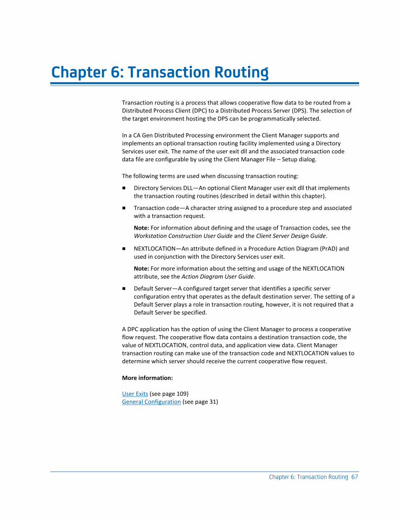
Chapter 6: Transaction Routing 67
Chapter 6: Transaction Routing
Transaction routing is a process that allows cooperative flow data to be routed from a Distributed Process Client (DPC) to a Distributed Process Server (DPS). The selection of the target environment hosting the DPS can be programmatically selected.
In a CA Gen Distributed Processing environment the Client Manager supports and implements an optional transaction routing facility implemented using a Directory Services user exit. The name of the user exit dll and the associated transaction code data file are configurable by using the Client Manager File – Setup dialog.
The following terms are used when discussing transaction routing:
■ Directory Services DLL—An optional Client Manager user exit dll that implements the transaction routing routines (described in detail within this chapter).
■ Transaction code—A character string assigned to a procedure step and associated with a transaction request.
Note: For information about defining and the usage of Transaction codes, see the Workstation Construction User Guide and the Client Server Design Guide.
■ NEXTLOCATION—An attribute defined in a Procedure Action Diagram (PrAD) and used in conjunction with the Directory Services user exit.
Note: For more information about the setting and usage of the NEXTLOCATION attribute, see the Action Diagram User Guide.
■ Default Server—A configured target server that identifies a specific server configuration entry that operates as the default destination server. The setting of a Default Server plays a role in transaction routing, however, it is not required that a Default Server be specified.
A DPC application has the option of using the Client Manager to process a cooperative flow request. The cooperative flow data contains a destination transaction code, the value of NEXTLOCATION, control data, and application view data. Client Manager transaction routing can make use of the transaction code and NEXTLOCATION values to determine which server should receive the current cooperative flow request.
More information:
User Exits (see page 109) General Configuration (see page 31)

Directory Services User Exit
68 Distributed Processing - Client Manager User Guide
Directory Services User Exit
The Client Manager Directory Services user exit is a dynamic-link library (DLL) that contains routines (or functions) to implement transaction routing.
■ The Directory Services user exit was created to allow code external to the Client Manager to determine the name of the server targeted by a cooperative flow request.
■ Directory Services provides accessibility to a user-defined process for determining the destination server of a cooperative flow request. The range of complexity for this user-defined process can vary depending on application needs.
■ Using Directory Services helps to exploit the capabilities of the multi-connect feature of the Client Manager by identifying the desired target without user intervention.
Note: Code for a sample Directory Services user exit is provided with the Client Manager installation, in iefdir.c. The iefdir.c source code is located in the \samples\ClientManager subdirectory of the directory where the Client Manager is installed. This code contains the description and sample usage of the Client Manager Directory Services API. Because the roles of these functions represent only a baseline behavior, the source code for the Directory Services user exit may require tailoring for the implementation of your specific transaction routing scheme. Exercise caution when modifying the user exit code. One or more of the supplied example subroutines may subject string data to modification due to the need to trim leading and trailing spaces. You must be careful when supplying strings constants to ensure they are stored within modifiable rather than read only memory.
The following examples and the Transaction Routing Flow illustration represent possible scenarios for when Directory Services should be considered:
■ Multiple client applications on a workstation that require transactions to be executed on different servers. For example, for Client App1, Tran2 runs on Server1 and for Client App2, Tran3 runs on Server2.
■ Single client applications on a workstation that require transactions to be executed on different servers. For example, for Client App1, Tran2 runs on Server1 and Tran3 on Server2.
■ Server application deployed on multiple servers, which means the transactions are the same on those servers. For example, for Client App3, Tran4 is installed on Server2 and Server3. This scenario requires the use of NEXTLOCATION to identify the target server destination because the same transaction resides on multiple servers.
If Directory Services is not enabled or if the Directory Services user exit returns a NULL value, transactions are routed to the Default Server—if one has been specified. Otherwise, an error is returned to the DPC application.
Directory Services User Exit
Chapter 6: Transaction Routing 69
The following diagram illustrates Transaction Routing Flow:
NEXTLOCATION
NEXTLOCATION is a CA Gen text attribute designed to assist the process of transaction routing by providing the Directory Services user exit with a value that can be used to identifying a target server name.
This attribute is set by a client application in a CA Gen procedure action diagram (PrAD) with a SET NEXTLOCATION statement. The attribute has a maximum size of 1000 character bytes. This size allows the flexibility to provide data that is adequate for Directory Services to identify a specific server name based on the NEXTLOCATION value.
Directory Services User Exit
70 Distributed Processing - Client Manager User Guide
The setting of this attribute to a meaningful value is especially critical in an environment where the same transaction resides on multiple servers (multi-server transaction environment).
Note: For NEXTLOCATION to have a meaningful role in the transaction routing process, the Client Manager Directory Services user exit must be enabled.
Transaction Code
A transaction code is a character string assigned to a procedure step and associated with a cooperative flow request. In the supplied Directory Services user exit sample, the transaction code is used to perform a lookup in the file IEFDIR.TRN, which maps transaction codes to cooperative flows and server names. The user exit performs the lookup and returns the name of the target server to be used to process the cooperative flow represented by the transaction code.
Default Server
The default server is a configured target server to which transactions are routed if either of the following conditions is true:
■ The Directory Services user exit is not enabled.
■ The Directory Services user exit is enabled but returns a NULL value.
If no default server is defined and the conditions above are true, the Client Manager returns an error message to the requesting DPC application.
A configured default server enables other features of the Client Manager, such as Auto Connect and Auto Logon.
More information:
General Configuration (see page 31) Configure a Default Server (see page 74)
Directory Services DLL Functions
Chapter 6: Transaction Routing 71
Directory Services DLL Functions
The Directory Services user exit DLL contains three functions that interface with the Client Manager. The functions, their descriptions, and the arguments passed are:
1. IEFDP_InitDir—Initializes any processes used by the sample Directory Services user exit. This function is called once and is the first Directory Services function called by Client Manager during execution initialization. The IEFDP_InitDir() reads in transaction codes and target server names in pairs from the transaction file (.TRN) and inserts them into a binary tree.
■ The Client Manager passes an argument that contains the name of the Client Manager's initialization file ( iefcmn.ini by default). The name of the transaction file is extracted from this initialization file. The transaction file name is defined within the Client Managers File - Setup dialog by setting the Dir. Svc. Input File parameter to name the appropriate file.
■ IEFDP_InitDir() returns a return code value to the Client Manager.
– If the function returns a value of zero (0) to the Client Manager, the Client Manager assumes that the initialization is either successful or that the transaction file name specified in the initialization file has been found and successfully processed.
– If the function returns a non-zero value to the Client Manager, the Client Manager assumes that the Directory Services capability is not available and sets the Directory Services Status to unavailable. Consult the Client Manager log file for possible causes of the failure.
The supplied sample transaction file, IEFDIR.TRN, must be modified to include the names of all application transactions and configured server names that are to take advantage of transaction routing.
Note: NEXTLOCATION does not use the IEFDIR.TRN file. However, the sample IEFDP_InitDir() returns an error message if no input file exists. Thus, the sample exit requires a file with dummy data or other trancode/server name pairs being used when NEXTLOCATION is not set.
Directory Services DLL Functions
72 Distributed Processing - Client Manager User Guide
2. IEFDP_SearchDir—Processes an inquiry and returns a target server name to the Client Manager.
■ The Client Manager passes to IEFDP_SearchDir() a single argument that contains two NULL-terminated strings, transaction code and NEXTLOCATION data.
– Using NEXTLOCATION Data—If data is provided in NEXTLOCATION, the sample implementation of IEFDP_SearchDir() assumes that NEXTLOCATION contains a 16-byte target server name and IEFDP_SearchDir() returns this value as the target server name.
– Using Transaction Code—If data is not provided in NEXTLOCATION, the sample implementation of IEFDP_SearchDir() enforces a one-to-one mapping between the transaction code and a target server by performing a binary search of the data previously loaded from the sample transaction file (IEFDIR.TRN), using the transaction code as the key field.
■ If an appropriate target server match cannot be found, the sample implementation of IEFDP_SearchDir() returns a NULL value to the Client Manager indicating a server name could not be found. Otherwise, the corresponding target server name is returned.
Note: Any value returned by IEFDP_SearchDir() needs to be defined as a target server within the Client Manager configuration in order to properly complete the routing of transactions to the selected target server.
3. IEFDP_CleanupDir—Provides the opportunity to perform any exit activities. This function is called at the termination of the Client Manager.
No arguments are passed.
More information:
User Exits (see page 109)
Enable Client Manager Directory Services
The Directory Services user exit must be enabled before the Client Manager can support transaction routing.
1. From the Client Manager window, select File>Setup.
2. At the File - Setup dialog, select Dir. Svc. DLL from the file list box.
3. Click Rename.
4. In the Setup - Change Filename dialog, enter the Directory Services DLL file name in the Filename entry field and click Ok. Note: You must always specify the complete file pathname of the .DLL file.

Directory Services and Client Manager Summary
Chapter 6: Transaction Routing 73
5. At the Change Filename Confirmation dialog, press Ok to return to the File - Setup dialog.
6. At the File - Setup dialog, select Dir. Svc. Input File from the file list box.
7. Click Rename.
8. In the Setup - Change Filename dialog, specify the Directory Services Input file name, depending on your Directory Services exit implementation. (For the sample code provided, this value identifies the input file, which contains the trancode and target server mapping. For more information, see the Directory Services User Exit section of the "User Exits" appendix in this guide.)
9. Click OK.
10. At the Change Filename Confirmation dialog, click OK to return to the File - Setup dialog.
11. Click OK to return to the Client Manager main window.
12. To save the changed configuration, select File, Save.
13. At the File – Save Configuration dialog, ensure the Save Initialization File checkbox is checked and click OK.
14. Exit and restart the Client Manager.
Client Manager Directory Services is enabled for use if the Directory Services Status field on the File – Setup dialog displays Available. To access this dialog, select File – Setup from the Client Manager main window.
More information:
User Exits (see page 109)
Directory Services and Client Manager Summary
The following table summarizes Client Manager Directory Services:
Directory Services Client Manager
Enabled and returns a target server name
Searches its list of configured target server names. If a match is found, the request is sent to that target server. If a match is not found, the Client Manager returns an error message to the client application.
Enabled but returns a NULL value
If a default server is defined, it is used. If no default server is defined, an error message is returned to the client application.

Directory Services and Client Manager Summary
74 Distributed Processing - Client Manager User Guide
Directory Services Client Manager
Not enabled If a default server is defined, it is used. If no default server is defined, an error message is returned to the client application.
Configure a Default Server
To configure a default server, at least one server must already be configured within the Client Manager.
Follow these steps:
1. Start the Client Manager.
2. From the main Client Manager window, select only one configured server in the Server Name list.
3. Select Server, Make Default.
4. Save the current configuration using the procedures in the chapter "Saving Configuration Files" in this guide.
More information:
Saving Configuration Files (see page 91)
Transaction Routing Events Summary
The DPC application sends a transaction request to a server application by initiating a cooperative flow. The resulting cooperative flow contains the transaction code and NEXTLOCATION. This cooperative flow initiates a series of transaction routing events in the Client Manager, which varies based on whether or not the Directory Services user exit is enabled.
Directory Services and Client Manager Summary
Chapter 6: Transaction Routing 75
The following represents a summarized sequence of transaction routing events with Directory Services enabled:
1. Upon startup, the Client Manager calls the IEFDP_InitDir() Directory Services user exit function. With the supplied sample user exit, this function reads a file containing a list of trancode-to-server mappings. This file should map each supported transaction code to the host name of the target server expected to service that transaction code.
2. A DPC application sends a transaction request containing the transaction code and, optionally, the NEXTLOCATION by issuing a dialog flow to a server application. (NEXTLOCATION is required to locate the name of the desired target server if the transaction resides on multiple servers).
3. The Client Manager receives the cooperative flow data, extracts the transaction code and NEXTLOCATION value, and passes those values to the IEFDP_SearchDir() Directory Services user exit function.
4. The IEFDP_SearchDir() function implements a user-defined transaction routing scheme. Schemes can include using a binary search routine or using the value of the NEXTLOCATION system attribute to identify the name of the destination target server.
5. The IEFDP_SearchDir() function then returns to the Client Manager either the name of a target server or a NULL value.
■ If Directory Services does not return a NULL value, Client Manager checks its target server configurations. If the desired target server is defined, the request is forwarded to that server.
■ If the IEFDP_SearchDir() function returns a NULL value to the Client Manager, the Client Manager attempts to send the request to the default server. If a default server has not been specified, the Client Manager cannot route the transaction and, as a result, returns an error to the client application.
6. When the Client Manager is shut down, the IEFDP_CleanupDir() Directory Services user exit function is called to allow any necessary cleanup to be performed.
The following represents a summarized sequence of transaction routing events with Directory Services disabled:
1. Client Manager receives the transaction request and attempts to forward the transaction request to the default server.
2. If a default server has not been specified, the Client Manager cannot route the transaction and returns an error to the client application.

Chapter 7: Server Access Security Using User ID and Password 77
Chapter 7: Server Access Security Using User ID and Password
The security features described in this chapter allow developers of generated Distributed Process Client (DPC) and Distributed Process Server (DPS) applications to develop their own security solutions. CA Gen provides security for its generated applications through user exits, configuration files, and logon dialogs.
Note: For a general discussion covering CA Gen security, see the Distributed Processing – Overview Guide.
Terminology
The following terms are used throughout this chapter:
Enhanced Security
Enhanced Security is a term used to indicate that a client cooperative flow request Common Format Buffer (CFB) contains the optional security offset section. The security offset section will contain the CA Gen CLIENT_USERID and CLIENT_PASSWORD system attribute values as defined by the generated GUI applications. Additionally, the security offset can contain an optional security token. Enhanced security is enabled using the WRSECTOKEN GUI runtime user exit.
Standard Security
Standard security is a term used to indicate that a client cooperative flow request CFB does not contain the optional security offset section. The CLIENT_USERID and CLIENT_PASSWORD attribute values are included in the CFB header area. Standard security is enabled using the WRSECTOKEN GUI runtime user exit.
No Security
Neither the CLIENT_USERID nor CLIENT_PASSWORD attribute values are inserted into any portion of the CFB. Using No security is the default configuration set by the WRSECTOKEN() GUI runtime user exit.
Terminology
78 Distributed Processing - Client Manager User Guide
Security Offset Section
An optional data area located in CFB of CA Gen that contains security data consisting of the values assigned to the CLIENT_USERID and CLIENT_PASSWORD attributes. Additionally, the Security Offset section of the CFB can contain an optional security token that can be set within the WRSECTOKEN GUI runtime user exit.
If present in the CFB, the security offset section is part of the data area that can be encrypted. Encryption is performed within the WRSECENCRYPT GUI runtime user exit.
Client User ID
The term Client User ID has various usages within a discussion of the Client Manager. Client User ID can be used in reference to the following topics:
■ Client User ID sometimes refers to the CLIENT_USERID system attribute within a CA Gen model. This attribute can be set by a GUI DPC using the SET Action Diagram statement. Specifying a value for this attribute is programmatically done as part of the client application.
The use of the CLIENT_USERID attribute during a cooperative flow is optional and depends on the application designer causing the cooperative flow to contain Enhanced Security data. The request to make use of Enhanced Security data for a given cooperative flow is controlled by the WRSECTOKEN GUI runtime user exit.
Assuming Enhanced security is being used, the values assigned to the CLIENT_USERID attribute can be used to identify the user id context associated with the user that initiates a cooperative flow request. In some cases, the specified value can be used to establish the user id context under which the DPS will be executed. The specified value is carried in the cooperative flow request as data and processed by the TIRSECV server side user exit.
Client Manager can process either Standard or Enhanced cooperative flow requests. The basic difference is if the CFB being processed contains a security offset area. Only those CFBs that contain a security offset area support the use of Enhanced Security, those that don't support the use of Standard Security.
■ When discussing Client Manager, the term Client User ID is used to refer to those Client User IDs specified as part the Client Manager configuration.
A default Client User ID value can be specified as part of the Client Manager configuration. Additionally, each individual target server can have its own User ID value specified in the Client Manager configuration file as part of its unique configuration definition.
Terminology
Chapter 7: Server Access Security Using User ID and Password 79
Client Password
Similar to Client User ID, the term Client Password has multiple usages within a discussion of the Client Manager. Client Password can be used in reference to the following topics:
■ Client Password sometimes refers to the CLIENT_PASSWORD system attribute within a CA Gen model. This attribute can be set by a GUI DPC using the SET Action Diagram statement. Specifying a value for this attribute is programmatically done as part of the client application.
The use of the CLIENT_PASSWORD attribute during a cooperative flow is optional and depends on the application designer causing the cooperative flow to contain Enhanced Security data. The request to make use of Enhanced Security data for a given cooperative flow is controlled by the WRSECTOKEN GUI runtime user exit.
Assuming Enhanced security is being used, the values assigned to the CLIENT_PASSWORD attribute can be used during the validation processing performed by the server execution environment. In some cases, the specified value can be used when validating the user id associated with the cooperative flow request. The specified value is carried in the cooperative flow request as data and processed by the TIRSECV server side user exit.
■ When discussing Client Manager, the term Client Password can also be used to refer to those Client Passwords specified as part the Client Manager configuration.
A default Client Password value can be specified as part of the Client Manager configuration. Additionally, each individual target server can have its own password value specified in the Client Manager configuration file as part of its unique configuration definition.
Target Server Security Level
Every target server defined to a Client Manager has its own Security Level attribute. The Security Level of a given target server indicates to the Client Manager that it should or should not attempt to make use of security data when processing flows to that target server environment. A server Security Level can be set to one of the following:
Remote
Indicates that the Client Manager should attempt to provide security data and perform security processing on all cooperative flows targeting this associated server. The Client Manager performs whatever security processing is appropriate for the target server based on its defined configuration (for example, CPI/C (LU 6.2) as compared to Sockets (TCP/IP)).
When the Security Level of a target server is determined to be Remote, the process of obtaining the security data to use for a given flow depends on the type of CFB received from the DPC application.
Terminology
80 Distributed Processing - Client Manager User Guide
Standard CFB:
The security data is obtained from the Client Manager configuration data, if defined. Otherwise, it may be necessary to prompt the application user for security data using a logon dialog.
Note: For details of the processing to obtain the security data from the Client Manager configuration, see the Derived Security Level Details (see page 85).
Enhanced CFB:
When processing an Enhance CFB, the choice of which security data the Client Manager will use depends on the setting of the CFB CMUseSecure flag byte. If set, the Client Manager will use the data specified in the security offset of the CFB, otherwise, the Client Manager will use the data provided by its configuration data the same as if the CFB received was a Standard CFB. The setting of the CFB CMUseSecure flag is influenced by the GUI runtime WRSECTOKEN user exit.
Regardless of which type of CFB is received by a Client Manager, the security data (user id and password) that is selected for use will be populated into the CFB header of the CFB.
None
Indicates that the Client Manager will not attempt to provide any security data, or provide any additional security processing for flows that target the associated server.
Defer
The determination of a given Server's Security Level is obtained from the Client Manager's Default Security Parameters setting. If the Client Manager's Default Security Level is set to None, the security level associated with the target server will be None. The same is true if the default setting is Remote. The security level associated with the target server will be Remote.
Derived Security Level
A derived security level is determined by taking into account the configured security level of the current target server and the default security level of the Client Manager. The hierarchical combination of these configurations is what is called the derived security level. The Client Manager attempts to derive the security level of a given server if their specified security level is set to Defer. A derived security level can be either Remote or None.
■ Remote—A derived security level of Remote indicates that security data comprised of a user id and password must be inserted into the header area of the CFB prior to transmission of the CFB to the target server environment.
■ None—A derived security level of None indicates the security data should not be inserted into the CFB header.
DPC Application Security Responsibilities
Chapter 7: Server Access Security Using User ID and Password 81
CMUseSecure CFB Flag Byte
If the WRSECTOKEN user exit indicates that the CFB contains a security offset, the Client Manager uses the provided security data as part of its processing of the cooperative flow request. Refer to the WRSECTOKEN GUI runtime user exit for details on how this is accomplished.
Note: You can find a description of the WRSECTOKEN user exit in the Distributed Processing – Overview Guide.
If the target server has a derived security level of Remote, the Client Manager uses the value of the CMUseSecure CFB flag to determine whether the security data located in the CFB offset should be used. If the flag is set, the data in the CFB security offset is used. If not set, the Client Manager uses the security data located in its configuration file or prompts the user with a logon dialog.
Encryption CFB Flag byte
This CFB flag can be set for either a request CFB or a response CFB. Both the DPC and DPS runtime code support the use of an encryption user exit. The CFB encryption flag is set by the DPC or DPS runtime if their respective encryption user exit returns indicate the CFB has been encrypted.
The Client Manager is only concerned that a CFB request has been encrypted when:
The selected target server has a derived security level of Remote.
■ The CFB being processed contains a security offset area.
■ The CMUseSecure CFB flag has been set.
■ For the Client Manager to use the data located in the CFB security offset area, it must first decrypt the CFB buffer.
DPC Application Security Responsibilities
A generated GUI DPC application is responsible for notifying the Client Manager how to obtain security data if the target server derived security level is set to Remote. The GUI application notifies the Client Manager by way of the CFB. The CFB is populated by the GUI runtime. Values coded by the user in the WRSECTOKEN user exit determine how the CFB is populated.

Client Manager Security Responsibilities
82 Distributed Processing - Client Manager User Guide
The WRSECTOKEN GUI runtime client security user exit must be modified by the user to set the return code to one of the following three values:
■ SecurityUsedStandard
The values of the CLIENT_USERID and CLIENT_PASSWORD system attributes will be populated into the CFB header area by the GUI runtime. The security offset area will not be added to a Standard Security CFB.
■ SecurityNotUsed
The resulting CFB is similar to the Standard Security CFB in that it does not contain a security offset area. When WRSECTOKEN returns SecurityNotUsed, the CLIENT_USERID and CLIENT_PASSWORD attribute values are ignored and are not placed anywhere within the CFB by the DPC. This is the default behavior of the WRSECTOKEN user exit implementation.
■ SecurityUsedEnhanced
An enhanced security CFB contains a security offset area. This area will contain the values of the CLIENT_USERID and CLIENT_PASSWORD system attributes. Additionally, the user-written code in WRSECTOKEN can cause an optional security token to be added to the CFB security offset.
The CLIENT_USERID attribute value is also placed into the User ID field within the CFB header. The password data is not added to the header for an enhanced security CFB.
If WRSECTOKEN returns a value of SecurityUsedEnhanced that indicates the Client Manager should use the data contained in the enhanced security offset area if the target server has a derived security level of Remote.
Client Manager Security Responsibilities
The Client Manager is responsible for providing security data to support target server requirements. The Client Manager processes security data (user id and password) to satisfy the following two requirements, if the target server has a derived security level of Remote:
■ To add security data to the CFB header. The security data in the CFB header is not directly accessible to the logic of a DPS application. However, this security data, in most DPS execution environments, is used to establish the user context under which the DPS will execute. For example, the supplied user id and password may be used to sign on the user. The signed-on user establishes the context under which the transaction will execute.
■ To provide security data (user id and password) for those transports that are capable of using it as part of their protocol. Currently, the LU 6.2 protocol uses user id and password security data as part of the underlying conversation allocate (FMH-5).
Client Manager Security Responsibilities
Chapter 7: Server Access Security Using User ID and Password 83
Client Manager Retrieving the Security Data
The Client Manager only attempts to obtain security data for a cooperative flow request if the target server selected to process the request has a derived security level of Remote. How and where the Client Manager obtains the user id and password security data is dependent on the type of CFB being processed:
■ If the CFB is a Standard Security CFB (the CFB does not contain a security offset area), the Client Manager retrieves the security data from the Client Manager configuration data.
■ If the CFB is an Enhanced Security CFB, the Client Manager first determines whether the security data located in the security offset area should be considered. If the Enhanced Security CFB has the CMUseSecure CFB flag byte set, the Client Manager retrieves the security data from within the CFB security offset area.
If the enhanced security offset area is used, the Client Manager determines whether the CFB is encrypted. If the CFB is encrypted, the Client Manager calls its DECRPYT() user exit to decrypt the CFB prior to extracting the user id and password security offset area.
If the enhanced security offset area is not used, the Client Manager handles obtaining the needed security data in a manner similar to how it would process a Standard Security CFB.
If the Client Manager determines that it must use its configuration to obtain the needed security data, the Client Manager proceeds in the following manner:
■ Uses the Server Security Parameters settings for the selected target server
■ Uses the Client Manager Default Security Parameters setting
■ Uses the security data supplied by the Client Manager Logon dialog
Setting Target Server Security Parameters
Cooperative flows that target a secure server environment may require that the flow include security data such as user id and password. The target server environment uses this security data to restrict access to only those users it deems authorized.
The Client Manager Server Configuration dialog is used to set these security parameters specific to a particular server connection. The derived security level, mentioned in the following table, is used to determine if and from where the user id and password are obtained. Derived security has been discussed in sections presented earlier within this chapter.
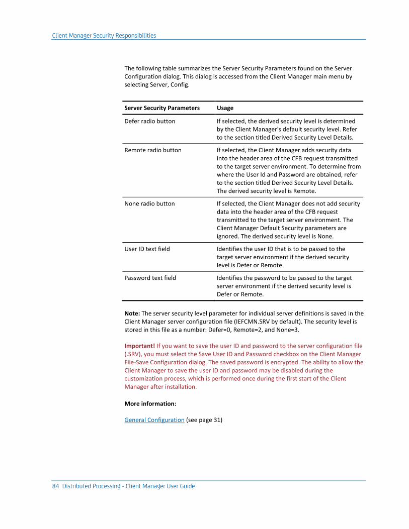
Client Manager Security Responsibilities
84 Distributed Processing - Client Manager User Guide
The following table summarizes the Server Security Parameters found on the Server Configuration dialog. This dialog is accessed from the Client Manager main menu by selecting Server, Config.
Server Security Parameters Usage
Defer radio button If selected, the derived security level is determined by the Client Manager's default security level. Refer to the section titled Derived Security Level Details.
Remote radio button If selected, the Client Manager adds security data into the header area of the CFB request transmitted to the target server environment. To determine from where the User Id and Password are obtained, refer to the section titled Derived Security Level Details. The derived security level is Remote.
None radio button If selected, the Client Manager does not add security data into the header area of the CFB request transmitted to the target server environment. The Client Manager Default Security parameters are ignored. The derived security level is None.
User ID text field Identifies the user ID that is to be passed to the target server environment if the derived security level is Defer or Remote.
Password text field Identifies the password to be passed to the target server environment if the derived security level is Defer or Remote.
Note: The server security level parameter for individual server definitions is saved in the Client Manager server configuration file (IEFCMN.SRV by default). The security level is stored in this file as a number: Defer=0, Remote=2, and None=3.
Important! If you want to save the user ID and password to the server configuration file (.SRV), you must select the Save User ID and Password checkbox on the Client Manager File-Save Configuration dialog. The saved password is encrypted. The ability to allow the Client Manager to save the user ID and password may be disabled during the customization process, which is performed once during the first start of the Client Manager after installation.
More information:
General Configuration (see page 31)
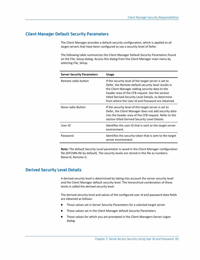
Client Manager Security Responsibilities
Chapter 7: Server Access Security Using User ID and Password 85
Client Manager Default Security Parameters
The Client Manager provides a default security configuration, which is applied to all target servers that have been configured to use a security level of Defer.
The following table summarizes the Client Manager Default Security Parameters found on the File, Setup dialog. Access this dialog from the Client Manager main menu by selecting File, Setup.
Server Security Parameters Usage
Remote radio button If the security level of the target server is set to Defer, the Remote default security level results in the Client Manager adding security data to the header area of the CFB request. See the section titled Derived Security Level Details, to determine from where the User Id and Password are obtained.
None radio Button If the security level of the target server is set to Defer, the Client Manager does not add security data into the header area of the CFB request. Refer to the section titled Derived Security Level Details.
User ID Identifies the user ID that is sent to the target server environment.
Password Identifies the security token that is sent to the target server environment.
Note: The default Security Level parameter is saved in the Client Manager configuration file (IEFCMN.INI by default). The security levels are stored in this file as numbers: None=0, Remote=2.
Derived Security Level Details
A derived security level is determined by taking into account the server security level and the Client Manager default security level. The hierarchical combination of these levels is called the derived security level.
The derived security level and values of the configured user id and password data fields are obtained as follows:
■ Those values set in Server Security Parameters for a selected target server
■ Those values set in the Client Manager default Security Parameters
■ Those values for which you are prompted in the Client Managers Server Logon dialog
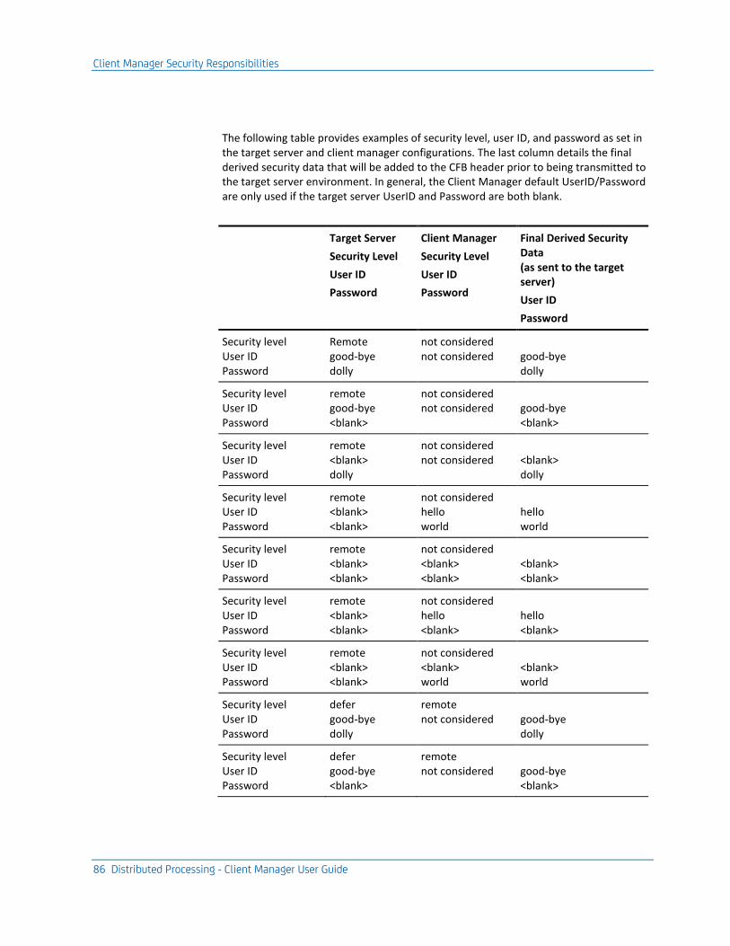
Client Manager Security Responsibilities
86 Distributed Processing - Client Manager User Guide
The following table provides examples of security level, user ID, and password as set in the target server and client manager configurations. The last column details the final derived security data that will be added to the CFB header prior to being transmitted to the target server environment. In general, the Client Manager default UserID/Password are only used if the target server UserID and Password are both blank.
Target Server
Security Level
User ID
Password
Client Manager
Security Level
User ID
Password
Final Derived Security Data (as sent to the target server)
User ID
Password
Security level User ID Password
Remote good-bye dolly
not considered not considered
good-bye dolly
Security level User ID Password
remote good-bye <blank>
not considered not considered
good-bye <blank>
Security level User ID Password
remote <blank> dolly
not considered not considered
<blank> dolly
Security level User ID Password
remote <blank> <blank>
not considered hello world
hello world
Security level User ID Password
remote <blank> <blank>
not considered <blank> <blank>
<blank> <blank>
Security level User ID Password
remote <blank> <blank>
not considered hello <blank>
hello <blank>
Security level User ID Password
remote <blank> <blank>
not considered <blank> world
<blank> world
Security level User ID Password
defer good-bye dolly
remote not considered
good-bye dolly
Security level User ID Password
defer good-bye <blank>
remote not considered
good-bye <blank>
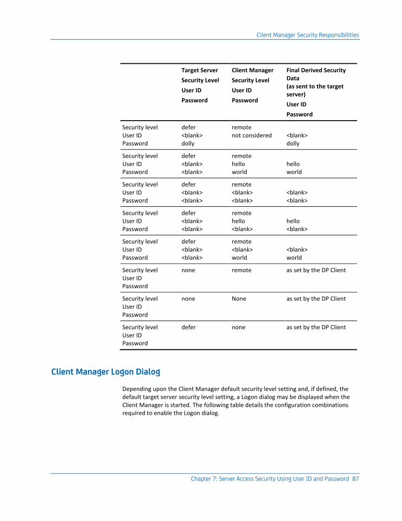
Client Manager Security Responsibilities
Chapter 7: Server Access Security Using User ID and Password 87
Target Server
Security Level
User ID
Password
Client Manager
Security Level
User ID
Password
Final Derived Security Data (as sent to the target server)
User ID
Password
Security level User ID Password
defer <blank> dolly
remote not considered
<blank> dolly
Security level User ID Password
defer <blank> <blank>
remote hello world
hello world
Security level User ID Password
defer <blank> <blank>
remote <blank> <blank>
<blank> <blank>
Security level User ID Password
defer <blank> <blank>
remote hello <blank>
hello <blank>
Security level User ID Password
defer <blank> <blank>
remote <blank> world
<blank> world
Security level User ID Password
none remote as set by the DP Client
Security level User ID Password
none None as set by the DP Client
Security level User ID Password
defer none as set by the DP Client
Client Manager Logon Dialog
Depending upon the Client Manager default security level setting and, if defined, the default target server security level setting, a Logon dialog may be displayed when the Client Manager is started. The following table details the configuration combinations required to enable the Logon dialog.
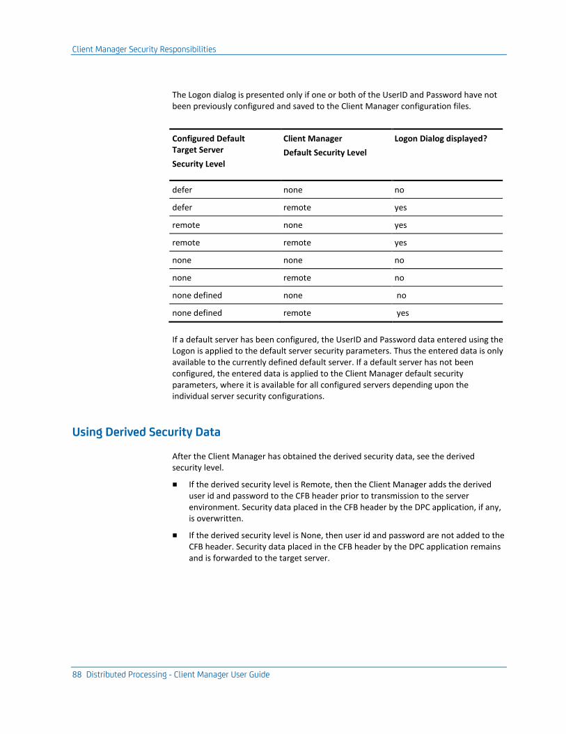
Client Manager Security Responsibilities
88 Distributed Processing - Client Manager User Guide
The Logon dialog is presented only if one or both of the UserID and Password have not been previously configured and saved to the Client Manager configuration files.
Configured Default Target Server
Security Level
Client Manager
Default Security Level
Logon Dialog displayed?
defer none no
defer remote yes
remote none yes
remote remote yes
none none no
none remote no
none defined none no
none defined remote yes
If a default server has been configured, the UserID and Password data entered using the Logon is applied to the default server security parameters. Thus the entered data is only available to the currently defined default server. If a default server has not been configured, the entered data is applied to the Client Manager default security parameters, where it is available for all configured servers depending upon the individual server security configurations.
Using Derived Security Data
After the Client Manager has obtained the derived security data, see the derived security level.
■ If the derived security level is Remote, then the Client Manager adds the derived user id and password to the CFB header prior to transmission to the server environment. Security data placed in the CFB header by the DPC application, if any, is overwritten.
■ If the derived security level is None, then user id and password are not added to the CFB header. Security data placed in the CFB header by the DPC application remains and is forwarded to the target server.
Decryption of Common Format Buffer
Chapter 7: Server Access Security Using User ID and Password 89
Decryption of Common Format Buffer
The CFB data transmitted from DPC applications can optionally be encrypted. A flag byte in the CFB header signifies the data has been encrypted. This flag byte is used to notify the receiver of the CFB that it has been encrypted. It is the responsibility of the receiver to decrypt the CFB.
With respect to the Client Manager, the data in the CFB only needs to be decrypted if the security data located in the security offset is to be used when sending the cooperative flow request to a target server that has a derived security level of Remote.
Client Manager DECRYPT User Exit
The DECRYPT Client Manager user exit is intended to provide a user-written decryption routine that must be able to correctly decrypt the CFB previously encrypted by the GUI runtime user exit WRSECENCRYPT.
The Client Manager passes the encrypted portion of the CFB to the DECRYPT exit routine. The exit returns a decrypted version of the data it was passed as input.
On return from the DECRYPT user exit, the Client Manager parses out the user ID and password. The Client Manager uses this retrieved security data when servicing the associated cooperative flow request.
The Client Manager decrypts the CFB for its internal use only. When the CFB is forwarded on to the target server environment, it remains in the encrypted state as received from the originating DPC.
Notes:
■ Also, see the security discussion within Distributed Processing – Overview Guide for a detailed discussion of encryption and security within a DP application.
■ For more information about user exits, see the User Exit Reference Guide.
More information:
User Exits (see page 109)
Errors
Any errors returned from the decryption user exit or encountered while processing the user exit are returned to the DPC and the cooperative flow is aborted.

Translating UserID and Password
90 Distributed Processing - Client Manager User Guide
Translating UserID and Password
For those transports that use UserID and Password as part of their protocol (currently LU6.2) an optional Conversation Instance Data user exit is provided to facilitate any required pre-translation of the UserID and Password text prior to being sent to the transport layer. The two user exit entry points are described in the following sections.
CIDE_INIT()
This entry point is invoked only once, during initialization of the Client Manager transport support code. Future calls to CIDE_PROC() are enabled or disabled depending upon the return value from this exit entry point.
CIDE_PROC()
This entry point, invoked once per request flow, can be used to perform a pre-translation of the UserID and Password text data before they are passed to the transport protocol layer.
Note: For more information about user exits, see the User Exit Reference Guide.
More information:
User Exits (see page 109)
Chapter 8: Saving Configuration Files 91
Chapter 8: Saving Configuration Files
The configuration parameters for a Client Manager are saved in two distinct files, an initialization file, and a target server file. You can save these configuration files using the default file names, or choose your own file names.
The default name of the initialization file is IEFCMN.INI. This file contains values for the following Client Manager attributes:
■ Auto-Connect to Server
■ Auto-Reset Server Connection
■ Client Manager Log File Name
■ Logging Level
■ Statistic Refresh State and Refresh Interval
■ Default Security Parameters
■ Default Target Server Name
■ Name of server configuration (.srv) file
■ Directory services, dll and tran file, file names
The default name of the target server configuration file is IEFCMN.SRV. For each configured server, this file contains:
■ Name of the server
■ Text description for the server
■ Type of transport API
■ Test transaction name
■ Server security parameters
■ Communication dll name
■ Applicable transport parameters
Retaining the .INI and .SRV extensions aids in keeping track of file functions. It is also recommended that you use file name prefixes that are related so that it is easier to distinguish collections of related files.
Saving the Client Manager Configuration
92 Distributed Processing - Client Manager User Guide
The purpose of the Client Manager Configuration files is to provide one set of files for each end user. When the Client Manager is used on a single-instance Windows workstation, the configuration files belong to that user—in which case, the default names, IEFCMN.INI, IEFCMN.SRV, and IEFCMN.LOG are usually sufficient. When using the Multi-Instance Client Manager, more names must be created because each user needs a separate set of configuration files.
Saving the Client Manager Configuration
The Save Configuration dialog is unique within the Client Manager, as it is the only dialog whose use can be tailored. During the first execution following Client Manager installation, the Client Manager presents a series of first time use configuration dialogs. One of these dialogs asks if you want the Client Manager to save userids and passwords to the Client Manager configuration files. If, during the initial Client Manager configuration, you indicate that you want to save user ids and passwords, the Save Configuration dialog contains an additional check box. This check box allows users to designate whether they want userids and passwords saved to the configuration files. If they choose not to save userids and passwords, the check box is not displayed on the Save Configuration dialog.
Using the following steps, the Client Manager configuration can be saved while a Client Manager is active:
1. From the Client Manager main window, select File, Save.
2. On the File – Save Configuration dialog, verify that check boxes for the Initialization file and Server Configuration file are checked.
3. Click OK to return to the main dialog.
4. There is no need to stop and restart the Client Manager to allow the new configuration settings to take effect. Updates to the Client Manager are dynamic and take effect while the Client Manager is active.
Note: If you change file names from within the File – Save Configuration dialog the current configuration is saved under these names. This is similar to the Save As option in other programs.
Upon exiting the Client Manager, the Save Configuration dialog appears to allow the user to save updates. This dialog appears only if the user modified the active Client Manager configuration.

Saving the Client Manager Configuration
Chapter 8: Saving Configuration Files 93
Changing Configuration File Names
Follow these steps:
1. Select File, Setup from the Client Manager main window.
2. On the File – Setup dialog, select the file name you want to change.
3. Click Rename.
This displays the Setup – Change Filename dialog.
4. Change the name of the file as desired and click OK.
5. Click OK on the Change Filename Confirmation dialog.
This propagates the changed names to the File – Setup dialog.
6. Repeat Steps 2 through 7 for the remaining file names to be changed.
7. Click OK on the File – Setup dialog.
8. On the main window, select File, Save and verify that both check boxes on the File – Save Configuration dialog are marked.
9. Click OK to return to the main dialog.
The Client Manager must be stopped and restarted before the new configuration settings can take effect.
Note: If you change file names from within the File – Save Configuration dialog, the current configuration is saved with these names. This is similar to the Save As option in other programs.

Chapter 9: Testing the Client Manager 95
Chapter 9: Testing the Client Manager
The main GUI window of the Client Manager has a sub-menu item that gives you the ability to simulate a cooperative flow request. Every target server defined to a Client Manager has its own Test Transaction attribute. This Test Transaction attribute identifies the transaction code name to be used when constructing a simulated cooperative flow request. The Server – Send Test Tran submenu item is a non-dialog directive that causes the Client Manager to send a Test Transaction to all selected servers.
When directed to send a Test Transaction, the Client Manager builds a simulated cooperative flow request. The Client Manager submits the request to itself and handles the response.
Similar to any other cooperative flow request, the processing of a Test Transaction creates a new connection to a selected target server if a connection does not already exist. If a connection already exists, the Client Manager processes the Test Transaction flow using that existing connection. The Client Manager assumes the role of the Distributed Processing Client (DPC). CA Gen provides an ECHO transaction server for various target server execution environments supported by CA Gen. The ECHO transaction assumes the role of the Distributed Processing Server (DPS). The combination of the Client Manager and the supplied ECHO transactions give you the opportunity to test the network connection between the Client Manager and one or more execution environments which potentially host the target DPS applications.
Server Configuration
Each server defined within a Client Manager has a Test Transaction attribute. This attribute is also known as the Echo Tran or Test Tran. For more information about how to specify the Test Tran for a given target server, see Configuring Client Manager Server Connections (see page 45) .
More information:
Configuring Client Manager Server Connections (see page 45)

Sending a Test Transaction
96 Distributed Processing - Client Manager User Guide
Sending a Test Transaction
The ability to send a designated Test Transaction to one or more target servers is provided using a Send Test Trans submenu directive that is available on the Server main menu. If you select more than one target server, the test transaction associated with each individual server is sent to its respective server.
The ECHO Transaction
CA Gen provides a unique version of an ECHO transaction server for each server execution environment to which a Client Manager can connect (CICS, IMS, Windows Transaction Enabler, UNIX Transaction Enabler, and Tuxedo). The ECHO transactions do not test your generated applications. Rather, they are used in cooperation with the Client Manager to test the network connection between the client workstation and the execution environments that potentially host one or more target DPS applications.
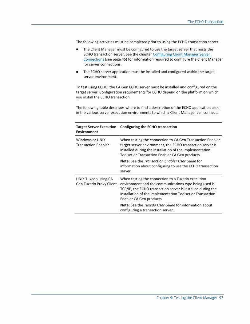
The ECHO Transaction
Chapter 9: Testing the Client Manager 97
The following activities must be completed prior to using the ECHO transaction server:
■ The Client Manager must be configured to use the target server that hosts the ECHO transaction server. See the chapter Configuring Client Manager Server Connections (see page 45) for information required to configure the Client Manager for server connections.
■ The ECHO server application must be installed and configured within the target server environment.
To test using ECHO, the CA Gen ECHO server must be installed and configured on the target server. Configuration requirements for ECHO depend on the platform on which you install the ECHO transaction.
The following table describes where to find a description of the ECHO application used in the various server execution environments to which a Client Manager can connect.
Target Server Execution Environment
Configuring the ECHO transaction
Windows or UNIX Transaction Enabler
When testing the connection to CA Gen Transaction Enabler target server environment, the ECHO transaction server is installed during the installation of the Implementation Toolset or Transaction Enabler CA Gen products.
Note: See the Transaction Enabler User Guide for information about configuring to use the ECHO transaction server.
UNIX Tuxedo using CA Gen Tuxedo Proxy Client
When testing the connection to a Tuxedo execution environment and the communications type being used is TCP/IP, the ECHO transaction server is installed during the installation of the Implementation Toolset or Transaction Enabler CA Gen products.
Note: See the Tuxedo User Guide for information about configuring a transaction server.

Testing a Server Connection Using the ECHO Transaction
98 Distributed Processing - Client Manager User Guide
Target Server Execution Environment
Configuring the ECHO transaction
z/OS CICS When testing LU6.2, TCP/IP, or ECI connections to the CICS target server environment, the ECHO transaction server is installed during the installation of the Implementation Toolset for z/OS product.
The ECHO program is supplied in the CA Gen Load Library (ISPLLIB) provided with the Host Encyclopedia or z/OS IT software.
Ensure the ECHO program is made available to CICS in the DFHRPL concatenation and that the relevant transaction and program definitions have been done.
Note: For information about configuring to use the ECHO transaction server, see the z/OS Implementation Toolset Installation Guide or the Host Encyclopedia and Host Construction Installation Guide.
z/OS IMS When testing LU6.2 or TCP/IP connections to z/OS IMS target server environments, the ECHOI transaction server is installed during the installation of the Implementation Toolset for z/OS product.
The ECHOI program is supplied in the CA Gen Load Library (ISPLLIB) provided with the Host Encyclopedia or z/OS IT software.
Ensure the ECHOI program is made available to an application IMS Load Library and that the relevant transaction and program definitions have been done.
Note: For information about configuring to use the ECHO transaction server, see the z/OS Implementation Toolset Installation Guide or the Host Encyclopedia and Host Construction Installation Guide.
Testing a Server Connection Using the ECHO Transaction
The Client Manager can be used to test direct connections to servers or can be used to test server connections supported through the use of a CA Gen Communications Bridge.

Testing a Server Connection Using the ECHO Transaction
Chapter 9: Testing the Client Manager 99
The following illustration depicts the Client Manager direct connect test environment:
The following is an illustration of a Client Manager connecting to the target server execution environment by way of a Communications Bridge.

Testing a Server Connection Using the ECHO Transaction
100 Distributed Processing - Client Manager User Guide
This procedure assumes the applicable third party communications software has been configured, initialized, and started on all test machines.
1. Verify the target server environment is active.
■ LU6.2(CPI-C) (z/OS CICS and z/OS IMS)
If necessary, contact the CICS/IMS administrator to verify that the CICS/IMS region is up (available) and/or to acquire the LU6.2 sessions for the independent LU associated with your Client Manager. A session between CICS/IMS and the SNA service provider must be established.
Note: For target servers using z/OS server environments, see Host Encyclopedia and Host Construction Installation Guide and z/OS Implementation Toolset Installation Guide.
■ TCP/IP (Sockets)
– Transaction Enabler (Windows and UNIX)
Start AEFUF and AEFAD
Note: For UNIX target systems using the Transaction Enabler, see the Transaction Enabler User Guide. For Windows servers using Transaction Enabler, see the Windows Implementation Toolset User Guide.
– Tuxedo Proxy Client (UNIX)
Start the Tuxedo Proxy Client and the Tuxedo bulletin board with the configured ECHO transaction server.
Note: For using Tuxedo Proxy Clients, see the Tuxedo User Guide.
– TCP/IP to Enterprise Java Beans CFB Converter Services (Windows and UNIX)
Note: For using EJB Converter Services, see the Distributed Processing - Enterprise JavaBeans User Guide for EJB configuration details.
– z/OS CICS: CICS TCP/IP Direct Connect
Note: For target servers using z/OS CICS, see the Host Encyclopedia and Host Construction Installation Guide and the z/OS Implementation Toolset Installation Guide.
– z/OS CICS: CICS Socket Listener
Note: For target servers using z/OS CICS, see the Host Encyclopedia and Host Construction Installation Guide and the z/OS Implementation Toolset Installation Guide.
Testing a Server Connection Using the ECHO Transaction
Chapter 9: Testing the Client Manager 101
– z/OS IMS: IMS TCP/IP Direct Connect
Note: For target servers using z/OS IMS, see the Host Encyclopedia and Host Construction Installation Guide and the z/OS Implementation Toolset Installation Guide.
– Communications Bridge
Note: For target servers using a CA Gen Communications Bridge, see the Distributed Processing – Communications Bridge User Guide.
■ NonStop
Does not support Echo transaction server.
2. On a client workstation, start the Client Manager and if necessary configure the server connection for connecting to the desired target server. See the Configuring Client Manager Server Connections chapter for details about configuring target server connections.
3. Verify the test transaction name specified on the Client Manager Server Configuration dialog. This dialog is launched from the Client Manager main window by selecting Server, Config.
■ ECHO is the CA Gen provided transaction name for all servers.
■ If the target server is a Communications Bridge and the Bridge is serving a CICS region using ECI as its transport, verify that the Test Tran. Server name is ECHO. ECHO is the CA Gen provided transaction for CICS. The Comm. Bridge uses the name specified in the Test Tran Server entry field as the name of the program that is invoked by the resulting CICS Distributed Program Link (DPL).
Note: For additional information on using ECI from a Comm. Bridge, see the Distributed Processing – Communications Bridge User Guide.
4. On the Client Manager main window, select one or more server names from the list.
5. On the Client Manager main window, select Server, Send Test Trans.
Testing a Server Connection Using the ECHO Transaction
102 Distributed Processing - Client Manager User Guide
6. Verify that the Client Manager establishes a connection with the selected target servers. Use the status field on the Client Manager main window to track the connection status.
■ If your server configuration target is a CICS Socket Listener, the connection will be non persistent. The connection will be closed when the response is returned to the Client Manager. Thus the status field should change from DISCONNECTED to CONNECTED and then back to DISCONNECTED. For all other non CICS Socket Listener server configurations, the connection is persistent, long lived. The status field should change from DISCONNECTED to CONNECTED and remain CONNECTED indicating you have established a connection.
■ Verify that a pop-up window appears indicating that the resulting cooperative flow request was successfully returned.
■ If the status sequence goes from DISCONNECTED to CONNECTING to DISCONNECTED, you should check the Client Manager's log file and resolve any connectivity problems before continuing the test procedure.
■ Watch for pop-up error messages from the communications products as the test executes. If an error message appears, use the information in the Client Manager's log file to determine the cause of the failure. Access the log file by selecting File, Browse, Log File from within the Client Manager application.
Note: You may need to change the logging level to see more detailed logging information.
To change the logging level from the Client Manager main menu, follow these steps:
1. Select File, Setup.
2. On the File – Setup dialog, select a more verbose logging level from within the Logging Level group box.
3. Click OK to return to the main menu.
4. On the main window, select File, Save.
5. Verify that both check boxes on the File – Save Configuration dialog are marked.
6. Click OK to return to the main dialog.
The logging level change takes effect immediately. It is not necessary to restart the Client Manager when changing Logging Level.
7. Re-execute the ECHO test.
Using a User-Written Test Transaction
Chapter 9: Testing the Client Manager 103
Using a User-Written Test Transaction
Users of the Client Manager can choose to use a different Test Transaction other than the ECHO applications provided by CA Gen. The Server Configuration associated with the target server allows the user to enter the name of their Test Tran (and for ECI to a Comm. Bridge, the name of their Test Tran. server).
The Client Manager uses the Test Transaction data that is specified for each individual target server when constructing a simulated cooperative flow. Because the Client Manager is acting as the DPC applications, the behavior of a user-written test server application must be the same as the ECHO applications that are provided by CA Gen. The simulated test cooperative flow built by the Client Manager consists of a Common Format Buffer (CFB) header, User Action area, and the Next location area. The Next Location area is populated with the name of the target server. The Client Manager does not send or expect to receive import or export view data.
Using a Client Application to Test Connectivity
Any DPC application that makes use of the Client Manager creates a connection to its target server if an existing connection does not already exist. You can develop a test CA Gen Distributed Processing application to test connectivity from the Client Workstation to a server execution environment.
The following steps can be used to test the client application. These steps assume a successful connection to the target server ECHO transaction server has already been performed:
1. The DPS application server must be installed, configured, and activated as required by the target server environment
2. On the client workstation, start the client application and exercise the application as required to initiate a cooperative flow.
3. The client cooperative flow request should, if not currently active, result in a connection from the Client Manager to the target server environment.
4. Client Manager Server connection status can be monitored from the Client Manager main window. The Status column of the server list reflects the status of the server connection.
5. Verify proper execution of the cooperative flow as appropriate for the application being tested.
If errors are encountered, use the information found in the Client Manager log file to determine the cause of the failure. Access the log file by selecting File, Browse, Log File from the Client Manager Main menu. You may also need to investigate log files on the target server environment for help determining the cause of failure.

Chapter 10: Client Manager Server Flow Statistics 105
Chapter 10: Client Manager Server Flow Statistics
The Client Manager has a statistic gathering capability that tracks the number of cooperative flows processed, as well as the total number of bytes sent and received. A dialog displaying a summary of the statistic can be displayed. Optionally the statistics can be updated on demand or periodically as determined by a configurable time parameter.
Statistics are maintained for:
■ Number of Transactions
■ Total Elapsed Time Since Client Manager Startup
■ Server Response Times
■ Total Bytes Sent
■ Total Bytes Received
Statistics - Summary Dialog
The Client Manager Statistics - Summary dialog displays real-time byte transfer statistical data for the target server transport. To display the statistics dialog from the Client Manager main window select the Statistics, Summary menu items.
Note: The fields that provide total byte counts of data routed through the Client Manager have a special multiplier field that follows the data field. The first letter of each of these abbreviations denotes the multipliers: Kilo, Mega, Giga, and Tera.
The statistical counts are restarted at zero when:
■ The Client Manager is first started
■ The Clear pushbutton on the Statistics – Summary dialog is pressed
■ The Statistics , Clear All main window menu item is selected
The display-only fields on this dialog include:
Transactions
Total number of transactions sent and received by Client Manager
Elapsed Time
The number of minutes since the Client Manager was started
Statistics - Refresh Parameters Dialog
106 Distributed Processing - Client Manager User Guide
Response Time
Maximum, minimum, and average response times (in units of seconds)
Total Bytes Sent
Cumulative total of data bytes sent out with transaction from Client Manager
Total Bytes Received
Cumulative total of data bytes received from transaction into Client Manager
Statistics - Refresh Parameters Dialog
User configurable parameters enable and set the frequency of periodic updates of the statistics displayed in the Statistics – Summary dialog. On the Client Manager main window select Statistics, Refresh to display the Statistics – Refresh Parameters dialog.
Refresh On/Off
These radio buttons enable or disable the periodic update of the Statistics – Summary dialog. Select the On button to enable the periodic update feature. The default value is Off.
The Summary – Statistics dialog is not automatically updated if the refresh feature is not active. You can still manually update the statistics by selecting the Statistics, Refresh Now Client Manager window menu items.
Interval
The Interval entry field controls the length of time in whole seconds between refreshes of the Summary – Statistics dialog. The default value is 60 seconds.
Appendix A: Error Messages 107
Appendix A: Error Messages
For messages representing communication errors that occur with CA Gen Distributed Processing applications, see the Message Reference Guide.
Additional messages providing details of communications failure can be found in the Client Manager log file. You can view the log files with an ASCII text editor or from within the Client Manager main window using the File, Browse, Log File menu items.
Setting the Logging Level to Tracing
The Client Manager logging level can be changed to alter the amount of data dumped to the log file.
To change the log level:
Follow these steps:
1. Select File, Setup from the main Client Manager window.
2. Set the desired tracing level. The Trace Logging group box contains the trace level controls. Tracing is the most verbose level while Errors is the least verbose level.
3. Re-execute the failing cooperative flow.
Note: Using the Trace logging level may produce large log files.
More information:
General Configuration (see page 31)

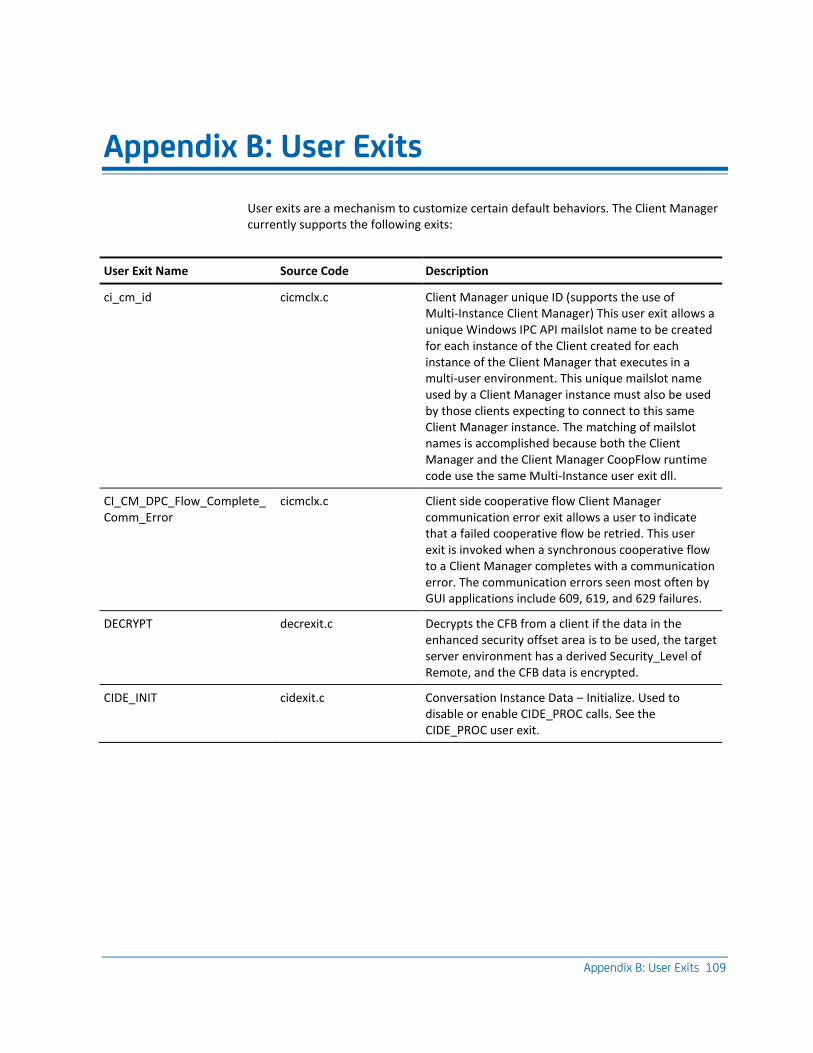
Appendix B: User Exits 109
Appendix B: User Exits
User exits are a mechanism to customize certain default behaviors. The Client Manager currently supports the following exits:
User Exit Name Source Code Description
ci_cm_id cicmclx.c Client Manager unique ID (supports the use of Multi-Instance Client Manager) This user exit allows a unique Windows IPC API mailslot name to be created for each instance of the Client created for each instance of the Client Manager that executes in a multi-user environment. This unique mailslot name used by a Client Manager instance must also be used by those clients expecting to connect to this same Client Manager instance. The matching of mailslot names is accomplished because both the Client Manager and the Client Manager CoopFlow runtime code use the same Multi-Instance user exit dll.
CI_CM_DPC_Flow_Complete_Comm_Error
cicmclx.c Client side cooperative flow Client Manager communication error exit allows a user to indicate that a failed cooperative flow be retried. This user exit is invoked when a synchronous cooperative flow to a Client Manager completes with a communication error. The communication errors seen most often by GUI applications include 609, 619, and 629 failures.
DECRYPT decrexit.c Decrypts the CFB from a client if the data in the enhanced security offset area is to be used, the target server environment has a derived Security_Level of Remote, and the CFB data is encrypted.
CIDE_INIT cidexit.c Conversation Instance Data – Initialize. Used to disable or enable CIDE_PROC calls. See the CIDE_PROC user exit.
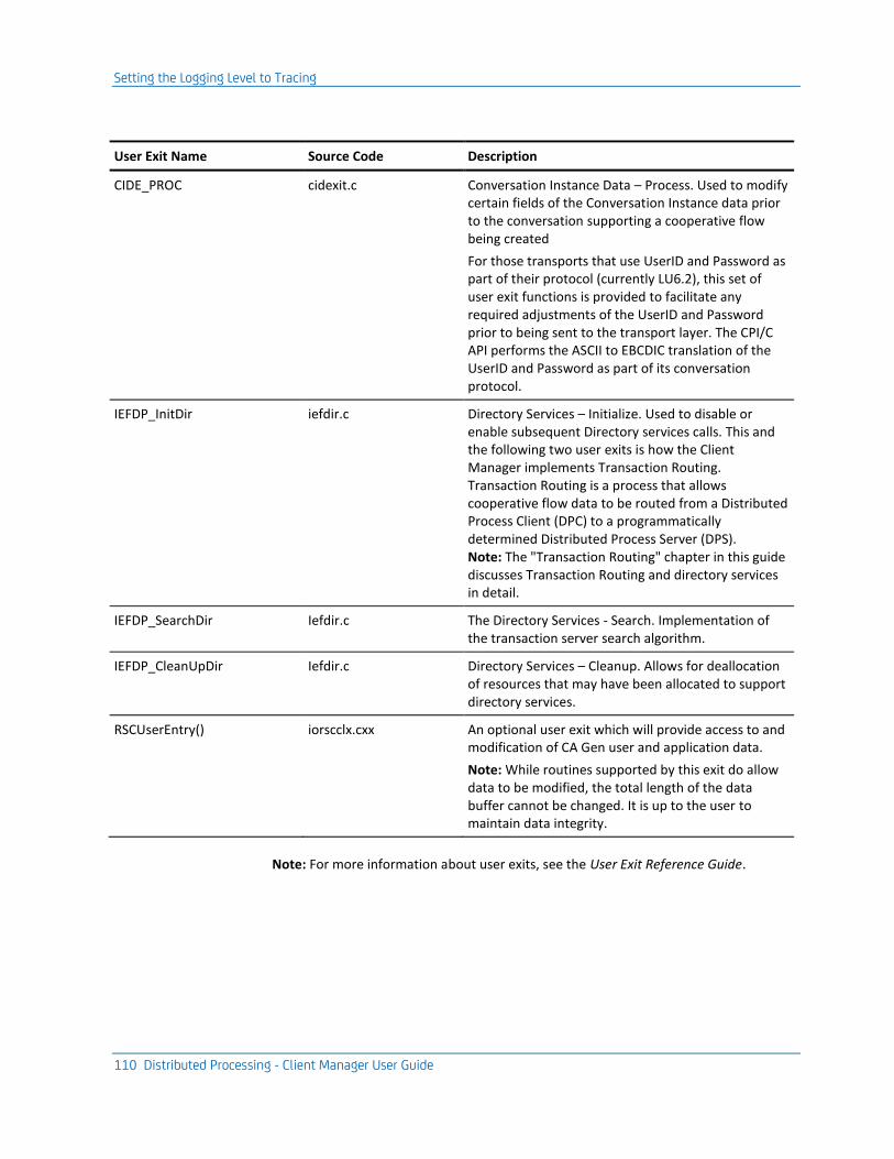
Setting the Logging Level to Tracing
110 Distributed Processing - Client Manager User Guide
User Exit Name Source Code Description
CIDE_PROC cidexit.c Conversation Instance Data – Process. Used to modify certain fields of the Conversation Instance data prior to the conversation supporting a cooperative flow being created
For those transports that use UserID and Password as part of their protocol (currently LU6.2), this set of user exit functions is provided to facilitate any required adjustments of the UserID and Password prior to being sent to the transport layer. The CPI/C API performs the ASCII to EBCDIC translation of the UserID and Password as part of its conversation protocol.
IEFDP_InitDir iefdir.c Directory Services – Initialize. Used to disable or enable subsequent Directory services calls. This and the following two user exits is how the Client Manager implements Transaction Routing. Transaction Routing is a process that allows cooperative flow data to be routed from a Distributed Process Client (DPC) to a programmatically determined Distributed Process Server (DPS). Note: The "Transaction Routing" chapter in this guide discusses Transaction Routing and directory services in detail.
IEFDP_SearchDir Iefdir.c The Directory Services - Search. Implementation of the transaction server search algorithm.
IEFDP_CleanUpDir Iefdir.c Directory Services – Cleanup. Allows for deallocation of resources that may have been allocated to support directory services.
RSCUserEntry() iorscclx.cxx An optional user exit which will provide access to and modification of CA Gen user and application data.
Note: While routines supported by this exit do allow data to be modified, the total length of the data buffer cannot be changed. It is up to the user to maintain data integrity.
Note: For more information about user exits, see the User Exit Reference Guide.
Index 111
Index
A
AEFAD, ECHO for TCP/IP to AEFAD • 96
C
CA Gen • 9, 15, 16, 18, 22, 23, 31 Client Manager • 9 Client Manager, dependency • 31 Common Format Buffer • 16 Communication Bridge • 23 Communications bridge • 22 Distributed Processing (DP) client/server
application • 15 Window Manager application • 18
Client Manager • 9, 16, 18, 20, 21, 22, 24, 25, 26, 27, 28, 31, 32, 37, 38, 39, 74, 82, 83, 85, 87, 92, 95, 103, 105 Automatic connection • 39 communicating • 9 Configuration files • 31 Configuring TCP/IP socket • 74 Default Server configuration • 26 Directory Service • 38 Execution • 31 Features • 22 Installation • 31 Log files • 103 Logon Dialog • 87 Modifying • 22 Multi-instance • 21 Multiple connections • 22 Network environment • 22 Resides on • 16 Save Configuration dialog • 92 Security • 27 Security data, retrieving • 83 Security parameters, default • 37, 85 Security responsibilities • 82 Server flow Statistics • 105 Single-instance • 20 Starting methods • 32 Statistics • 28 Support for communications • 24 Target server environments • 9 Testing logical network connections • 95
Transaction routing • 25 User exit • 21 Using commcfg.ini file • 18 Working • 9
Client Workstation • 16 ClientUser ID • 77 CMICXnnN.DLL • 43 CMUseSecure flag • 77 Common Format Buffer (CFB) • 16, 77, 81, 89
CMUseSecure flag byte • 77 Decryption • 89 Encryption CFB flag byte • 77 Enhanced CFB • 77 GUI Runtime • 81 Security offset • 77 Standard CFB • 77
Communication • 15, 22, 107 Byte streams • 15 Concurrent sessions • 22 Error messages • 107
Configuration files • 31, 91 Client Manager • 31 Saving • 91
Cooperative flow • 15, 16, 23, 37, 70, 77 Client User ID attribute • 77 Data transmission • 23 Informational messages • 37 transaction code • 70
D
Default Server • 70 Directory Services • 26, 68, 71, 72, 73
And Client Manager summary • 73 DLL functions • 71 Enabling • 72 User exit DLL • 26
Directory Services DLL, user exit • 67 Distributed Processing Client (DPC) application • 9,
16 Distributed Processing Client (DPC) application,
Security data, obtaining • 81 Distributed Processing Server (DPS) application • 9,
16 DLL functions, role of Directory Services • 71

112 Distributed Processing - Client Manager User Guide
E
ECHO • 96 LU6.2 platform to CICS • 96 Prerequisites • 96 TCP/IP to AEFAD • 96 TCP/IP to Tuxedo • 96
ECHOI, Transaction server • 98 Encryption CFB flag • 77 Environment • 41, 42
Multi-instance • 42 Single-instance • 41
Error Messages • 107
F
File name, Saving configuration files • 91
I
iefcmn.ini, configuration file • 31 iefcmn.srv, configuration file • 31 Inter-Process Communications (IPC) mechanisms •
23
L
Log files, tracing • 37 Logging level, Setting to tracing • 107
M
Mailslots • 23 Message, communication error • 107 Multi-Instance Client Manager • 21
N
NEXTLOCATION - CA Gen system attribute • 69
P
PATH environment variable • 36 Procedure Action Diagram (PrAD) • 67
S
Save Configuration dialog, tailoring • 92 Saving configuration files • 91 Security • 77, 83
Client Password • 77 ClientUser ID • 77 CMUseSecure flag, Client Manager • 77 Derived security level • 77
Encryption CFB flag • 77 Enhanced Security • 77 No Security • 77 Offset section • 77 Standard Security • 77 Target server parameters, setting • 83 Target server security level • 77
Security Server configuration • 83 Server flow statistics • 105, 106
configuring • 105 Refresh parameters dialog • 106 Summary dialog • 105
Server Machine • 17 Shared memory • 23 Single-Instance Client Manager • 20
T
TCP/IP • 96 ECHO for TCP/IP to Tuxedo • 96 ECHO to AEFAD • 96
Testing • 96 ECHO for LU6.2 platform to CICS • 96 ECHO for TCP/IP to AEFAD • 96 ECHO for TCP/IP to Tuxedo • 96 Prerequisites for ECHO • 96
Testing, Client Manager • 95 Tracing, log files • 37 Tracing, setting the logging level • 107 Transaction routing • 25, 67, 68, 69, 70, 74, 109
Client Manager • 25 Default server • 70 Defining • 67 Directory services • 68 Events summary • 74 NEXTLOCATION, CA Gen system attribute • 69
U
User exits • 21, 28, 35, 109 customizing • 21, 28 Directory Services • 35
User-Written Test Transaction, using • 103
W
Window Manager application • 18 Windows IPC mailslot API • 41