c76ib003en n instrman dma m v2.70 - propribory.ru
TRANSCRIPT
Measurewhat is measurableand make measurablethat which is not.Galileo Galilei (1564-1642)
Instruction Manual
DMA 4100 MDMA 4500 MDMA 5000 M
instrument software version: from 2.70(original instruction)


Instruction Manual
DMA 4100 MDMA 4500 MDMA 5000 M
instrument software version: from 2.70(original instruction)

Disclaimer
This document may contain errors and omissions. If you discover any such errors or if you would like to see more information in this document, please contact us at our address below. Anton Paar assumes no liability for any errors or omissions in this document.
Changes, copyright, trademarks etc.
This document and its contents may be changed or amended by Anton Paar at any time without prior notice.
All rights reserved (including translation). This document, or any part of it, may not be reproduced, changed, copied, or distributed by means of electronic systems in any form (print, photocopy, microfilm or any other process) without prior written permission by Anton Paar GmbH.
Trademarks, registered trademarks, trade names, etc. may be used in this document without being marked as such. They are the property of their respective owner.
Further information
Published and printed by Anton Paar GmbH, AustriaCopyright © 2015 Anton Paar GmbH, Graz, Austria
Address of the instrument producer: Anton Paar GmbHAnton-Paar-Str. 20A-8054 Graz / Austria – Europe
Tel: +43 (0) 316 257-0Fax: +43 (0) 316 257-257E-Mail: [email protected]: www.anton-paar.com
Date: 04 August 2015
Document number: C76IB003EN-N

Contents
1 About the Instruction Manual ................................................................................................................ 7
2 Safety Instructions.................................................................................................................................. 8
3 Measuring Principle.............................................................................................................................. 10
4 The Instrument – Overview .................................................................................................................. 11
5 Checking the Supplied Parts ............................................................................................................... 12
6 Functional Components....................................................................................................................... 15
6.1 View of the Front and Right Side .................................................................................................... 15
6.2 View of the Left Side ....................................................................................................................... 15
6.3 Rear View ....................................................................................................................................... 16
6.4 Operating Elements on the Main Screen........................................................................................ 17
6.5 Operating Elements on the Menu Screen....................................................................................... 19
7 Installing the Instrument ...................................................................................................................... 20
7.1 The Right Place .............................................................................................................................. 20
7.2 Mounting the Injection Adapters ..................................................................................................... 20
7.3 Checking for Leak Tightness .......................................................................................................... 21
7.4 Mounting the Hoses ........................................................................................................................ 21
7.5 Switching the Instrument On/Off ..................................................................................................... 22
7.6 Instrument Settings and First Checks ............................................................................................. 22
8 Checking, Adjusting, and Calibrating ................................................................................................. 23
8.1 Definitions ....................................................................................................................................... 23
8.2 Checks............................................................................................................................................ 23
8.2.1 Editing the Check Settings...................................................................................................... 23
8.2.2 Performing Density Checks .................................................................................................... 24
8.2.3 Viewing, Printing, or Exporting Current Check Data............................................................... 25
8.3 Adjustments .................................................................................................................................... 26
8.3.1 Performing an Air/Water Adjustment ...................................................................................... 26
8.3.2 Performing a Temperature Range Adjustment ....................................................................... 27
8.3.3 Performing a High Density/High Viscosity Adjustment (DMA 5000 M only) ........................... 27
8.3.4 Performing an Atmospheric Pressure Sensor Adjustment ..................................................... 28
8.3.5 Performing Special Adjustments............................................................................................. 28
8.3.5.1 Special Adjustments ....................................................................................................... 28
8.3.5.2 Special Adjustment for the Canadian Excise Alcohol Table ........................................... 29
8.3.6 Viewing, Printing or Exporting Adjustment Data ..................................................................... 29
8.3.7 Viewing, Printing or Exporting Adjustment History: KB Graph................................................ 30
8.3.8 Resetting the Adjustment Data to Factory Adjustment ........................................................... 30
8.3.9 Adjustment Analysis ............................................................................................................... 30
8.4 Calibrating....................................................................................................................................... 31
9 Defining and Using Methods ............................................................................................................... 32
9.1 Measuring Methods ........................................................................................................................ 32
9.2 Changing Methods.......................................................................................................................... 33
9.2.1 Defining the Measurement Settings of the Density Module.................................................... 33
9.2.2 Defining the Measurement Mode............................................................................................ 34
9.2.2.1 Defining Formula Parameters......................................................................................... 36
C76IB003EN-N 5

10 Measuring ............................................................................................................................................ 37
10.1 Sample Name ............................................................................................................................... 37
10.2 Filling Samples.............................................................................................................................. 37
10.3 Performing Measurements............................................................................................................ 39
10.4 Filling and Measurement Errors.................................................................................................... 40
10.4.1 Status Messages .................................................................................................................. 40
10.4.2 Error Messages..................................................................................................................... 40
11 Cleaning and Storing the Instrument ................................................................................................ 41
11.1 Cleaning and Drying the Measuring Cell ...................................................................................... 41
11.2 Storing the Instrument................................................................................................................... 42
11.3 Cleaning the Instrument Housing and Touch Screen ................................................................... 42
11.4 Repair ........................................................................................................................................... 42
Appendix A: Technical Data.................................................................................................................... 43
A.1: Measuring Performance ................................................................................................................ 43
A.2: General Technical Data................................................................................................................. 44
A.3: Wetted Parts.................................................................................................................................. 45
Appendix B: Measuring Special Samples.............................................................................................. 46
B.1: Degassing Samples....................................................................................................................... 46
B.2: Special Filling Techniques............................................................................................................. 46
Appendix C: Measuring under Special Conditions............................................................................... 48
C.1: Measuring at High Humidity/Low Temperature Conditions ........................................................... 48
C.2: Measuring at Low/High Temperatures .......................................................................................... 49
C.3: Measuring at High Pressures ........................................................................................................ 50
Appendix D: Camera Settings................................................................................................................. 51
D.1: Adjusting the Camera Position ...................................................................................................... 51
D.2: Setting the Camera Illumination .................................................................................................... 51
D.3: Saving a Camera Picture .............................................................................................................. 51
Appendix E: Trouble Shooting ............................................................................................................... 52
Appendix F: Output Quantities and Live Raw Data .............................................................................. 55
F.1: Output Quantities........................................................................................................................... 55
F.2: Live Raw Data ............................................................................................................................... 61
Appendix G: List of Quick Settings Parameters ................................................................................... 62
Appendix H: Density Tables.................................................................................................................... 64
Appendix I: Instrument Software Versions............................................................................................ 67
Appendix J: Calibration Approval .......................................................................................................... 71
Appendix K: Declaration of Conformity................................................................................................. 72
Appendix L: Menu Tree ........................................................................................................................... 73
6 C76IB003EN-N

1 About the Instruction Manual
1 About the Instruction ManualThis instruction manual informs you about the installation and the safe handling and use of the product. Pay special attention to the safety instructions and warnings in the manual and on the product.
The instruction manual is a part of the product. Keep this instruction manual for the complete working life of the product and ensure that it is easily accessible for all people involved with the product. If you receive any additions to or revisions of this instruction manual from Anton Paar GmbH, these must be treated as part of the instruction manual.
Conventions for safety messages
The following conventions for safety messages are used throughout this instruction manual:
TIP: Tip gives extra information about the situation at hand.
Typographical conventions
The following typographical conventions are used throughout this instruction manual:
DANGER
Danger indicates a hazardous situation which, if not avoided, will result in death or serious injury.
WARNING
Warning indicates a hazardous situation which, if not avoided, could result in death or serious injury.
CAUTION
Caution indicates a hazardous situation which, if not avoided, could result in minor or moderate injury.
NOTICENotice indicates a situation which, if not avoided, could result in damage to property.
Convention Description
<key> The names of keys and buttons are written between angle brackets.
menu level 1 > menu level 2
Menu paths are written in italics. Menu levels are connected by a closing angle bracket.
C76IB003EN-N 7

2 Safety Instructions
2 Safety Instructions• Read this instruction manual before using the
instrument.
• Make this instruction manual easily accessible to all persons working with the instrument.
• Follow all hints and instructions in this instruc-tion manual to ensure the correct use and safe functioning of the instrument.
2.1 Liability
• This instruction manual does not claim to address all safety issues associated with the use of the instrument and samples. It is your responsibility to establish health and safety practices and to determine the applicability of regulatory limitations.
• Anton Paar GmbH warrants the proper functioning of the instrument only if no modifications are made to mechanics, electronics, module firmware, or instrument software.
• Use the instrument only for the purpose described in the instruction manual. Anton Paar GmbH is not liable for damages caused by incorrect use of the instrument.
• The results delivered by the instrument depend not only on the correct functioning of the instrument but also on various other factors. We therefore recommend that you have the results checked (e.g. plausibility tested) by skilled personnel before consequential actions are taken based on the measured data.
2.2 Installation and Use
• The installation procedure shall be carried out only by authorized personnel who are familiar with the installation instructions.
• Use only accessories or consumables supplied or approved by Anton Paar GmbH.
• Ensure that all operators have been trained beforehand to use the instrument safely and correctly.
• Ensure that the instrument is sufficiently supervised during operation.
• In case of damage or malfunction, do not continue operating the instrument. Do not operate the instrument under conditions which could result in damage to goods or injuries or loss of life.
• If liquid has been spilled over the instrument, disconnect the instrument from the mains supply. Clean and dry the housing of the instrument. If you have a suspicion that liquid got into the instrument, have the instrument cleaned and checked for electrical safety by a service technician.
Operation in areas with risk of explosion
• The instrument is not explosion-proof and therefore must not be operated in areas with risk of explosion.
General precautions
• Observe and adhere to your national safety regulations regarding the handling of all substances associated with your measurements (e.g. use safety goggles, gloves, respiratory protection, etc.).
• Before a measurement, check the wetted parts of the instrument for chemical resistance to the samples and cleaning agents used.
• Take care that the liquids (samples and cleaning agents) or gases that you use are chemically compatible when they come into contact with each other. They shall not react exothermally or produce solid particles which might stick to the inner walls of the measuring cells.
• Before you start a measurement or cleaning procedure, take care that all parts, especially the measuring cells, the injection adapters, the hoses, and the waste vessel, are properly connected and in good condition.
• Before you start a measurement or cleaning procedure, check the injection adapters for leak tightness.
• Take measures that spilled liquids cannot get into plug connections or venting slots of electrical appliances.
• Connect the measuring system to the mains supply via a safety switch located at a safe distance from the instruments. In an emergency, turn off the power using this switch instead of the power switch on the instruments.
8 C76IB003EN-N

2 Safety Instructions
Precautions for flammable samples and cleaning agents
• Keep potential sources of ignition, like sparks or open flames, at a safe distance from the instrument.
• Place the instrument on a laboratory bench made of fireproof material, preferably bricks, ceramics, or stoneware.
• Store only the minimum required amount of sample, cleaning agents, and other flammable materials near the instrument.
• Do not spill sample/cleaning agents or leave their containers uncovered. Immediately remove spilled sample/cleaning agents.
• Ensure that the setup location is sufficiently ventilated. The environment of the instrument must be kept free of flammable gases and vapors.
• Provide fire-extinguishing equipment.
Transport
• Empty the measuring cell and all hoses before you move or lift the instrument.
• To move or lift the instrument, grasp the ledge on top of the instrument’s back side with one hand. Place the other hand under the display on the front side. There is a hollow for your fingers.
• Carry the instrument in front of you and keep it close to your body.
2.3 Maintenance, Service, Repairs
• Service and repair procedures may be carried out only by authorized personnel or by Anton Paar GmbH.
• For repairs, contact your local Anton Paar representative. The instrument must not be returned without the filled out "Safety Declaration for Instrument Repairs" and must be cleaned before return.
• You must not return instruments which are contaminated by radioactive materials, infectious agents, or other harmful substances that cause health hazards.
2.4 Disposal
• Concerning the disposal of the instrument, observe the legal requirements in your country.
C76IB003EN-N 9

3 Measuring Principle
3 Measuring PrincipleDefinition of density and specific gravity
The density ρ of a sample is defined as mass divided by volume:
The specific gravity SG is calculated by dividing the density of a sample by the density of pure water at 20 °C:
Density and Specific Gravity values are highly temperature-dependent.
The oscillating U-tube method
The sample is introduced into a U-shaped borosilicate glass tube that is being excited to vibrate at its characteristic frequency. The characteristic frequency changes depending on the density of the sample. Through a precise determination of the characteristic frequency and a mathematical conversion, the density of the sample can be measured.
The density is calculated from the quotient of the period of oscillations of the U-tube and the reference oscillator:
Concentration measurement
In binary mixtures, the density of the mixture is a function of its composition. Thus, the density value of a binary mixture can be used to calculate its composition with the aid of density/concentration tables.
This is also possible with so-called quasi binary mixtures. These are mixtures containing two major components and some additional components which are present in very small concentrations compared to the two main components. Many decarbonated soft drinks, for example, can be considered to be quasi binary solutions of sugar in water because the concentration of flavors and acids are very small compared to sugar and water. Thus, the sugar concentration can be measured with a density meter.
Note that the accuracy of the concentration measurement depends not only on the accuracy of the instrument, but also on the slope of the density/concentration correlation. This means, for example, that a density measurement with an accuracy of ±0.00001 g/cm3 will be converted into an ethanol value with a significantly smaller accuracy of ±0.025 % w/w. The accuracy of some typical concentration measurements is given in appendix A.1.
KA, KB .... apparatus constantsQ ............. oscillation period of the U-tube divided by
the oscillation period of the reference oscillator
f1, f2 ........ correction factors for temperature, viscosity, and nonlinearity
mV-----=
SGSample
Water--------------------=
density KA Q2 f1 KB f2– =
10 C76IB003EN-N

4 The Instrument – Overview
4 The Instrument – OverviewThe density and concentration meters of the DMA M series have been developed to combine highest precision with easy operation and robust design.
Measurement is based on the oscillating U-tube method that has been invented at a research institute in Graz, Austria, and first introduced onto the market by Anton Paar in 1967.
Features and Benefits
Accuracy
Your DMA M series instrument is equipped with the world’s most advanced digital density measurement technology:
• The period of oscillation of the U-tube is measured by optical pickups.
• Two integrated Pt 100 platinum thermometers together with Peltier elements provide an extremely precise thermostatting of the sample.
• ThermoBalance™: An additional reference oscillator provides long-term stability and enables precise measurements over the whole temperature range of the instrument with only one adjustment at 20 °C.
• Viscosity-related errors are automatically corrected over the full viscosity range by measuring the damping effect of the viscous sample which is subsequently taken account of in the calculation of the definitive density value.
• With DMA 5000 M, the precision for samples with high viscosity and high density can be increased by special adjustments with standards of high viscosity and high density.
• The built-in atmospheric pressure sensor enables correct air adjustment, as the air density is dependent on the atmospheric pressure.
Error detection
A major source of measuring errors with density meters are gas bubbles in the measuring cell. This issue is addressed by Anton Paar with two new features:
• FillingCheck™: The instrument automatically detects inhomogeneities and gas bubbles in the whole measuring cell by an advanced analysis of its oscillation pattern. Where necessary, a warning message is generated in real time for every single measurement.
• U-View™: Real-time images by a camera with zoom function enable you to visually inspect the measuring cell.
User interface
The touch screen user interface facilitates easy and intuitive operation in routine applications as well as in demanding scientific research work:
• For the most common applications, 10 measuring methods are predefined. Just select the method fitting your application, or create your own methods.
• Density values are automatically converted into concentration values for a large number of factory-programmed substances. You can add further substances as required by yourself.
• Optionally operate DMA 4100/4500/5000 M via external keyboard, mouse, or bar code reader.
• Optionally connect an external monitor or touch screen (VGA interface).
Compact and robust design
The instruments of the DMA M series keep up the tradition of the legendary previous DMA generations:
• Compact design
• Sealed housing
• Robust housing materials: coated aluminum (top and sides), aluminum (base and back), and polystyrene/butadiene (front)
C76IB003EN-N 11

5 Checking the Supplied Parts
5 Checking the Supplied PartsDMA 4100/4500/5000 M has been tested and packed carefully before shipment. However, damage may occur during transport.
1. Keep the packaging material (box, foam piece, transport protection) for possible returns and for further questions from the transport or insurance company.
2. Check the delivery for completeness by comparing the supplied parts to those listed in table 5-1.
3. If a part is missing, contact your Anton Paar representative.
4. If a part is damaged, contact the transport company and your Anton Paar representative.
Table 5-1: Supplied parts
Symbol Pcs. Article description Mat. no.
1 DMA 4100 MDMA 4500 MDMA 5000 M
153058153059153060
1 Power cordEuropeor USAor UKor Thailand
65146526566186579730
1 Instruction manuals English• Instrument• General Software FunctionsorInstruction manuals German• Instrument• General Software Functions
80812135322
87090135321
1 Density standard ultra-pure water 5x10 mL with certificate
96044
1 Waste vessel 500 mL 6210
12 C76IB003EN-N

5 Checking the Supplied Parts
1 Accessory kit DMA / DMA M 159958
containing:
2 m Hose 3x5 mm silicone (transparent)only for pressures up to 0.4 bar rel.
50814
7 Syringe 2 mL Luer 51974
2 Injection adapter Luer black 159026
2 Male Luer plug PTFE 63865
3 Adapter Luer cone PTFEonly for pressures up to 0.4 bar rel.
63863
1 Adapter UNF 1/4″ Luer male 64793
1 Hose clamp 21531
1 Phillips screwdriver PH-0x40 75030
Table 5-1: Supplied parts
Symbol Pcs. Article description Mat. no.
C76IB003EN-N 13

5 Checking the Supplied Parts
Table 5-2: Optional parts
Article description Mat. no.
Data handling
Keyboard German USB 80809
Keyboard USA USB 80807
Printer RS-232C incl. cable 9600N81 44737
Printer Epson TM-U220D 93362
RS-232 connection cable D-Sub 9-pin, 3 m 70429
Gender changer DB9M/DB9M 302592
Automatization
Sample changer Xsample 122 46534
Sample filling unit Xsample 22 81340
Sample changer Xsample 452 46535
Sample changer Xsample 530 105700
Filling and rinsing unit Xsample 352 81338
Sample handling unit Xsample 52 81339
Heated sample changer Xsample 452 H 84806
Heated filling and rinsing unit Xsample 352 H 84808
Protection
Protecting cover for keyboard 13350
Protection cap for USB interfaces 156194
Special funnel protection 82448
Special application accessories
Aerosol adapter 74650
Cooling kit DMA M 80810
Drying cartridge (with silica gel) 65085
Heating attachment for DMA M 83161
Syringes
Syringe 2 mL Luer (1 pc.) 51974
Syringes 2 mL Luer (10 pcs.) 58802
Syringes 2 mL Luer (1000 pcs.) 66399
Syringes 5 mL Luer (100 pcs.) 6772
14 C76IB003EN-N

6 Functional Components
6 Functional Components
6.1 View of the Front and Right Side
Fig. 6-1: View of the front and right side of the DMA M
6.2 View of the Left Side
Fig. 6-2: View of the left side
1 Power on LED2 Color PCAP touch screen3 Xsample slot cover plate
4 Sample inlet and outlet5 Air pump outlet
2
1
3
4
5
1 Blind covers for inlet and outlet of the optional cooling kit2 USB interfaces3 Protection cover for the USB interfaces
1 2 3
C76IB003EN-N 15

6 Functional Components
6.3 Rear View
Fig. 6-3: Rear view
1 S-BUS interfaces2 USB interface3 VGA interface4 RS-232 interface (COM)5 Ethernet interface6 CAN interfacea
7 "DRY AIR IN AIR PUMP" connector8 "DRY AIR IN BLOCK" connector
a for the connection of further measuring modules
9 Power switch10 Fuse holder11 Power inlet12 UL test mark13 Type plate with serial number14 Fan15 Carrying ledge
1 2
3
4
5
67
8
91011
14
15
1213
16 C76IB003EN-N

6 Functional Components
6.4 Operating Elements on the Main Screen
Fig. 6-4: Main screen example
Header
On the left side of the header, you find the name of the currently active method and the sample number.
On the right side of the header, you find a clock and the user indicator. The user indicator indicates the type of user that is currently logged on.
Content area
In the content area, the measuring values are displayed in small, medium, or large output fields. The layout of the content area can be defined in the settings of the current method according to your needs.
The progress bar at the bottom of the content area indicates whether the instrument is currently measuring or whether a measurement has finished.
Monitor mode
If you have not started a measurement yet, or if you have terminated a measurement by tapping <Stop>, the instrument is in the monitor mode and shows a continuous reading of the current measuring values.
Measuring mode
If you have started a measurement, a continuous reading of the current measuring values is shown until the measurement is finished. The final values
stay frozen on the screen until the next measurement is started. To unfreeze the screen and change to monitor mode, tap in the quick access area.
Buttons area
The buttons on the main screen have the following functions:
1 Header2 Output field3 Content area
4 Progress bar5 Buttons area6 Quick access area
1
2
3
4
5
6
Button Function
<Menu> Opens the main menu
<Quick Settings> Opens the quick settings list(only available in the "No Sample List" mode instead of the <Sample List> button)
<Sample List> Opens the current sample list
<Method> Opens the method list (to select a method)
<Start> Starts a measurement
<Stop> Stops and aborts a measurement
C76IB003EN-N 17

6 Functional Components
Quick access area
Fig. 6-5: Expanded quick access area
• To expand the quick access area, tap the icon on the quick access bar on the main screen.
• To collapse the quick access area, tap the icon in the upper right corner of the expanded quick access area.
• To browse items, use the page navigation in the header of the expanded
quick access area.
• To rearrange the items in the quick access area, tap (settings) in the upper left corner of the expanded quick access area. For details, see the General Software Functions Manual, section 4.8.
Function
Opens the message list.The general instrument status as well as all measuring errors that have occurred during the measurements of the currently active sample list are described in this list. The button changes its appearance depending on the current error status:
Green OK sign:The general instrument status and the error status of all measured samples of the current sample list are OK.
Yellow warning sign:• The instrument (or system) has a minor
problem (e.g. an air or water check is overdue, there is a printer problem etc.).
• There has been a filling error with one or more samples of the currently active sample list.
Red error sign:• The instrument (or system) has a major
problem that needs to be fixed before you continue with measurements(e.g. the sample changer is blocked).
• One or more samples of the current sample list could not be measured (e.g. the measuring cell is partly empty so that it cannot oscillate).
To reset the message list button to the green OK sign, confirm all error messages by tapping on the <X> button on the right side of the message. To confirm all messages in the list in one step, tap "Delete all" at the end of the list.The message list button will also be reset to the green OK sign if you delete the currently active sample list, see General Software Functions Manual, section 7.6.
U-View™: Opens the live camera view of the measuring cell.
Starts/stops the air pump.The air pump is off.
The air pump is on.
Unfreezes the screen after a finished measurement.The screen is frozen.
The screen is unfrozen. A continuous reading of the current measuring values is shown.
Displays information on using favorites.
18 C76IB003EN-N

6 Functional Components
6.5 Operating Elements on the Menu ScreenTo access the menu, tap <Menu> on the main screen.
Fig. 6-6: Menu screen examples
Header
On the left side of the header, you find the navigation path to your current position in the menu. You can go back to any menu position in your current path by directly tapping on the respective box of the navigation path. For details on using the <Add to Favorites> button, see the General Software Functions Manual, section 4.8.
Content area
In the content area, you find the menu options of the current menu level and the menu dialogs.
Buttons area
The buttons on menu screens have the following functions:
A1 HeaderA2 Menu level 1A3 <Back> buttonA4 <Home> buttonA5 Content area
B1 <Add to Favorites> buttonB2 Buttons areaB3 Content area
A1
A2
A3
A4
A5
B2
B1
B3
Button Function
<Back> Moves to the next higher menu level.
<Home> Returns to the main screen.
Buttons at the bottom of screens
Functions depending on the current menu or dialog
C76IB003EN-N 19

7 Installing the Instrument
7 Installing the InstrumentTo install the instrument, put it on a bench, mount injection adapters and hoses, and connect the instrument to the mains supply. Define general instrument settings and perform an air/water check to check the validity of the factory adjustment.
For the installation of an Xsample filling module, see the respective instruction manual.
7.1 The Right Place
DMA 4100/4500/5000 M is designed for operation under typical laboratory bench top conditions.
To guarantee temperature stability, do not place the instrument:
• near a heat source
• in a drafty place (e.g. near an air conditioner)
• on a vibrating surface or close to vibrating equipment
• in direct sunlight
7.2 Mounting the Injection Adapters
1. Take two injection adapters Luer with screws from the accessory kit.
2. Pull out the black plastic transport plugs from the tips of the injection adapters.
TIP: Keep the plastic transport plugs for later use. They can be used as an injection adapter tool to widen the tips of the adapters in case of leaks.
Fig. 7-1: Mounting the injection adapters Luer
3. Carefully insert the injection adapters into the openings of the adapter holding plate on the right side of the instrument, see Fig. 7-1.
4. Push both adapters towards the holding plate with moderate force.
5. Insert the screws through the bore holes of the adapters and screw them cautiously into the adapter holding plate until some resistance against further turning can be felt.
WARNING
Using hazardous or flammable chemicals as samples or cleaning liquids could lead to damage of the instrument and cause serious injuries unless special precautions are taken.• Observe the safety instructions in the section
"Special precautions for flammable chemicals" in section 2.
NOTICE• Ensure that the power plug and the power
switch are always easily accessible so that the instrument can be easily disconnected from the mains supply at any time.
• A strong built-in cooling fan dissipates heat through the bottom and the rear of DMA 4100/4500/5000 M. Ensure that the air flow is not blocked, and provide for a minimum distance of 10 cm (4 in) to walls behind and beside the instrument.
• High humidity or a measuring temperature that is significantly below the ambient temperature may lead to condensation within the measuring cell. Install a drying cartridge to avoid condensation, see appendix C.1.
CAUTION
If the screw for fastening the adapter is overtightened, the density measuring cell may be damaged. Harmful liquids leaking from the instrument may cause injuries.• Tighten the screw until some resistance
against further turning can be felt, and then stop to tighten the screw.The gap left between the holding plate and the adapter, where the thread of the screw can be seen, is approx. 3–8 mm (approx. 0.12–0.31 in).
20 C76IB003EN-N

7 Installing the Instrument
7.3 Checking for Leak Tightness
1. Close one adapter tightly with a male Luer plug.
2. Use a plastic syringe from the accessory kit to inject, with moderate pressure, air through the other adapter.
3. Wait a few seconds.
4. Release the plunger of the syringe.
- If the connections are tight, the plunger of the syringe will be slowly pushed back by the pressure in the measuring cell.
- If the connections are leaky, the plunger of the syringe will not move.In this case, repeat the mounting of the adapters.
TIP: Keep the plastic transport plugs for later use. They can be used as an injection adapter tool to widen the tips of the adapters in case of leaks.
7.4 Mounting the Hoses
To connect the waste vessel
1. Screw an adapter UNF ¼" Luer (from the accessory kit) into the threaded hole in the cap of the waste vessel.
2. Cut a piece of approx. 250 mm (10 in) length from the silicone hose included in the accessory kit.
3. Attach one end of the silicone hose to the adapter UNF ¼" Luer and fix it with a hose clamp (from the accessory kit).
4. Attach an adapter Luer cone PTFE (from the accessory kit) to the other end of the silicone hose and insert it into the rear injection adapter of DMA 4100/4500/5000 M.
Fig. 7-2: Connecting the waste vessel hose
To connect the silicone hose at the air pump outlet
1. Cut a piece of approx. 250 mm (10 in) length from the silicone hose included in the accessory kit.
2. Attach the silicone hose to the air pump outlet.
3. Attach an adapter Luer cone (from the accessory kit) to the other end of the silicone hose.
WARNING
Liquids leaking from the instrument may cause injuries and risk of fire.• Only use the supplied hose and waste vessel if
their materials are resistant to the samples and cleaning liquids that you are going to inject.
• If the supplied materials are not resistant, use other parts made of appropriate material.
C76IB003EN-N 21

7 Installing the Instrument
7.5 Switching the Instrument On/Off
1. Connect the power inlet of the instrument with the mains supply by the power cord.
2. Switch the instrument on using the power switch on the rear of the instrument.
The glowing green LED on the front side of the instrument indicates that the power is on.
3. Wait at least 15 minutes for the temperature to stabilize.
After power-on, the instrument needs approx. 15 minutes for temperature equilibration and internal temperature adjustments. During this time "temp. equilibration" is displayed.
TIP: Do not turn off the instrument during the night. This allows the measuring cell to achieve long term temperature stability.
4. To switch the instrument off, use the power
switch.
7.6 Instrument Settings and First Checks
After having installed the hardware, set the date and time, see General Software Functions Manual, section 6.1.1.
To check the validity of the factory adjustment, perform an air check and a water check.
The instrument has been factory adjusted over the whole temperature and viscosity range. However, during transport, the density adjustment can have been compromised.
To perform first checks
1. Wait at least 15 minutes after a restart for the temperature to stabilize.
2. To perform an air check, tap <Menu> and select Checks/Adjustments > Checks. Proceed as described in section 8.2.2.
3. To perform a water check, tap <Menu> and select Checks/Adjustments > Checks. Proceed as described in section 8.2.2.
4. If the check results are both OK, the instrument is ready for routine measurements.
5. If any check result is not OK, clean the measuring cell thoroughly and repeat the check.
6. If the check result is still not OK, perform an air/water adjustment, see section 8.3.1.
WARNING
High voltage at parts of the instrument can cause serious injuries or death.• Connect the instruments to the mains supply
only with protective earthing.• Never connect the instrument to the mains
supply with protective separation or protective insulation.
• Make sure that the non-fused earth conductor of the power cord is connected to earth.
NOTICEBefore switching the instrument on, make sure that the correct line voltage and line frequency are available (AC 100–240 V, 50/60 Hz). If large voltage fluctuations are to be expected, we recommend using a constant voltage source (UPS).
22 C76IB003EN-N

8 Checking, Adjusting, and Calibrating
8 Checking, Adjusting, and Calibrating
8.1 Definitions
Checking
Checking the correct operation of an instrument by measuring a sample of exactly known measurement properties, and comparing the result with the expected values.
Adjusting
Ensuring correct measurements in the future by filling in a sample of exactly known measurement properties (standard), and adjusting the instrument constants in a way that the known correct results are found by the instrument.
Usually, for a successful adjustment, at least two standards are needed with measurement properties that encompass the expected measurement results of your samples.
Calibrating
Calibrations are checking procedures which are carried out using certified standards. By comparing the measured result with the standard reference value, you can validate the quality of your measurements.
8.2 Checks
8.2.1 Editing the Check Settings
You can edit the name, method (custom check only), time interval, and the tolerance of density checks.
Tolerance
The factory presets for both air checks and water checks are:
To edit the settings of the air check and the water check
1. Tap <Menu> and select Setup > Expert Settings > Check Management to open the check administration list.
2. Highlight "AirCheck" or "WaterCheck", respectively, and tap <Edit> to open the three-step "Check Administration" wizard.
3. Enter a name for the check and tap <Next>.
4. Perform the following settings:
- Use the check box "GxP relevant" to define whether the check is relevant for "Good Practice" quality guidelines and regulations.
- Use the check box "Check execution reminder" to define whether the check is obligatory, and enter a time interval in days.
5. Tap <Next>.
6. Define the maximum allowed "Lower deviation" and "Upper deviation".
7. Tap <OK>.
To create a custom check
1. Tap <Menu> and select Setup > Expert Settings > Check Management to open the check administration list.
2. Tap <New> to open the three-step "Check Administration" wizard.
3. Perform the following settings:
- Enter a name for the check.- Select the method to define detailed method
settings for the check.
4. Tap <Next> and perform the following settings:
- Use the check box "GxP relevant" to define whether the check is relevant for "Good Practice" quality guidelines and regulations.
- Use the check box "Check execution reminder" to define whether the check is obligatory, and enter a time interval in days.
5. Tap <Next> and perform the following settings:
- Select a quantity and the corresponding unit.- Define the check tolerance by the "Lower
limit" and "Upper limit".- Optionally define the settings for further
quantities in the same way.
6. Tap <OK>.
DMA M Model Tolerance
DMA 4100 M 0.0002 g/cm3
DMA 4500 M 0.0001 g/cm3
DMA 5000 M 0.00005 g/cm3
C76IB003EN-N 23

8 Checking, Adjusting, and Calibrating
To edit a custom check
1. Tap <Menu> and select Setup > Expert Settings > Check Management to open the check administration list.
2. Highlight a "CustomCheck" and tap <Edit> to open the three-step "Check Administration" wizard.
3. Change the settings as required.
8.2.2 Performing Density Checks
By density checks, carried out in regular intervals, you can ensure that your density and concentration measurements consistently deliver results of high and stable accuracy.
With a density check, you fill a medium of known density (air, water, or any customer-specific standard liquid) into the measuring cell and compare the measured density with the reference value.
DMA 4100/4500/5000 M performs the water checks and air checks automatically at the measuring temperature of the currently active method. Also the predetermination/equilibrium type of measurement is used according to the selected method. The density of water and air at the measuring temperature is calculated and compared with the actually measured density. With water checks and custom checks, the value is calculated for the set temperature. With air checks, the value is calculated for the set temperature and the measured air pressure.
Custom checks are defined for a certain method and are always performed at the temperature of the selected method with the corresponding predetermination/ equilibrium type of measurement.
Air checks and water checks are available for any method.
When to do water checks and custom checks
Use the water check and the custom check to verify that the instrument is measuring with satisfactory accuracy. We recommend performing a water check or custom check every day before you start your measurements.
Perform additional water checks or custom checks as required and at your own discretion, e.g. when you get unexpected results.
When to do air checks
Use the air check to verify the efficiency of your cleaning and drying procedure. We recommend performing an air check every day after the measurements have been finished and the measuring cell has been cleaned and dried.
Perform additional air checks as required and at your own discretion, e.g. after the measurement of critical samples that might stick to the measuring cell (e.g. samples containing adhesives, sticky particles, proteins).
To perform a density check
1. Tap <Menu> and select Checks/Adjustments > Checks to open the checks list.
2. Highlight a water check, an air check, or a custom check in the list.
3. Tap <Start> and follow the instructions on the screen.
For a water check, use freshly degassed ultra-pure (bi-distilled or deionized) water.
For an air check, clean and dry the measuring cell thoroughly.
Use the camera image to check whether the measuring cell is clean or whether water has been filled bubble-free.
When the check is finished, the following information is displayed:
- Check name/type and check result ("Passed" or "Not passed")
- Date and time- Method used- Check result- User name- For water checks:
- Reference value calculated for the set temperature
- Lower deviation- Upper deviation- Measured value- Check result- Set temperature for the density cell
- For air checks:- Reference value calculated for the set
temperature- Lower deviation- Upper deviation- Measured value- Check result- Air pressure- Set temperature for the density cell
24 C76IB003EN-N

8 Checking, Adjusting, and Calibrating
- For custom checks:- Lower limit- Upper limit- Measured value- Check result
4. Tap <Print or Export> if you want to print or export the results of the check.
5. Tap <OK> or <Home> to exit the check routine.
If the water check has failed, we recommend taking corrective actions until the check is valid again:
• Examine the camera image included in the results to check whether the water has been filled bubble-free, see section 8.2.3.
• Check the quality of the water.
• Clean the measuring cell thoroughly.
• If the above mentioned actions do not help, perform an air/water adjustment.
To activate/deactivate the auto air check function
An auto air check can be initiated automatically before each measurement to ensure cleanliness of the measuring cell.
1. Tap <Menu> and select Setup > Measuring System Settings > Density Module.
2. Use the check box to activate/deactivate the auto air check function.
3. Tap <OK>.
To perform an auto air check
If a measurement is started, and the auto air check function is activated, the instrument will start an auto air check automatically.
1. Follow the instructions on screen.
2. Examine the measuring cell or use the camera image to check whether the measuring cell is clean. Clean and dry the measuring cell thoroughly if necessary.
3. Tap <OK> to start the auto air check.
- If the auto air check succeeds, fill the sample into the measuring cell and start your measurement by tapping <OK>.
- If the auto air check fails, you can take corrective actions and restart the auto air check by tapping <OK>, or you can cancel the measurement by tapping <Cancel>.
8.2.3 Viewing, Printing, or Exporting Current Check Data
The total number of entries in the check history is limited to 100.
To view check data
1. Tap <Menu> and select Data Memory > Check Data.
An overview of the available check data is displayed.
2. To view check data in detail, highlight a list item and tap <Details>.
To print or export check data
1. Tap <Menu> and select Data Memory > Check Data.
2. To print all check data on paper or to a PDF file, or to export all check data as an MS Excel file or text file, tap <Print or Export> and follow the instructions on the screen.
3. To print or export single check data, tap <Details> and then <Print or Export>.
Use and to scroll through the data list.
NOTICE• Auto air check results will not be saved in the
check data memory.• Auto air check limits are set according to the
air check limits.
C76IB003EN-N 25

8 Checking, Adjusting, and Calibrating
8.3 Adjustments
8.3.1 Performing an Air/Water Adjustment
An air/water adjustment has to be performed if the water check has failed with "not passed" as result, and using freshly degassed ultra-pure (bi-distilled or deionized) water and cleaning the measuring cell did not help.
The adjustment media are dry air and freshly degassed ultra-pure (bi-distilled or deionized) water.
The ThermoBalance™ technology allows for precise measurements over the whole temperature range with only one adjustment at 20 °C. To achieve the highest possible precision of measurements at different temperatures, you can additionally perform a temperature range adjustment, see section 8.3.2.
The air/water adjustment takes 5–10 minutes if the instrument is already clean and dry and equilibrated to 20 °C.
The adjustment procedure can be aborted by tapping <Cancel>.
To set the reference values for the air/water adjustment
The reference values for air can be selected according to your needs. They are either based on the formula of
- Spieweck and Bettin1 or- CIPM2.
The reference values for water can be selected according to your needs. They are either based on the formula of
- Spieweck and Bettin3 or- CIPM4 / IAPWS5.
(The CIPM formula is limited to 0–40 °C only, so for temperatures above 40 °C, the IAPWS formula is used.)
The factory adjustment has been set using reference values for the density of air (humidity 50 %) and water based on the formula of Spieweck and Bettin1,3. This formula covers the whole measuring range (0–95 °C) of the instrument.
1. Tap <Menu> and select Setup > Measuring System Settings > Density Module.
2. Use the drop-down box "Air Table" to select the preferred reference table.
3. Use the drop-down box "Water Table" to select the preferred reference table.
4. Tap <OK> to save your settings.
TIP : For use in metrology, the CIPM density formula is the preferred standard over its recommended range (0–40 °C) at pressures near atmospheric. The formula should not be extrapolated outside this range.Densities from the IAPWS formula are consistent with the CIPM standard within the range of validity of the CIPM formula. Outside the CIPM range of validity, the IAPWS formula is the preferred method for obtaining accurate densities of water.
To perform an air/water adjustment
1. Tap <Menu> and select Checks/Adjustments > Air/Water Adjustment.
2. Rinse the measuring cell.
TIP: If you use undenatured ethanol as the final rinsing liquid, only 3–4 minutes drying time are required.
3. Tap the <Air Pump on> button to dry the measuring cell.
4. Tap <OK>.
5. Enter the air humidity and the atmospheric pressure.
The air humidity is set to 50 % per default.
1 F. Spieweck, H. Bettin: Review: Solid and liquid density determination. tm – Technisches Messen 59 (1992) 7–8, pp. 285–292.
2 A. Picard, R.S. Davis, M. Gläser, K. Fujii. Metrologia 45 (2008), pp. 149–155.3 Cf. Spieweck/Bettin, p. 291.4 M. Tanaka, G. Girard, R. Davis, A. Peuto, N. Bignell. Metrologia 38 (2001), pp. 301–309.5 International Association for the properties of water and Steam: Release on the IAPWS formulation 1995 for the
thermodynamic properties of ordinary water substance for general and scientific use [1996]. Available at www.iapws.org.
NOTICEYou have to readjust the instrument after changing the selected air and/or water table.
NOTICEThe choice of reference table also affects derived quantities (e.g. Apparent Density, SG, API values, etc.).All factory-set concentration tables consist of calculated data based on the reference values according to Spieweck and Bettin.
26 C76IB003EN-N

8 Checking, Adjusting, and Calibrating
The atmospheric pressure displayed is measured automatically by a built-in sensor.
6. Tap <OK>.
The air adjustment routine is carried out.
7. Fill freshly degassed ultra-pure (bi-distilled or deionized) water into the measuring cell and tap <OK>.
Be careful to fill the water without air bubbles.
TIP: If the water has been filled without air bubbles, you can ignore a possible error message "Density Condition: filling warning" during the adjustment routine. The coefficients for the FillingCheck™ function will also be adjusted during the adjustment procedure.
The water adjustment routine is carried out.
When the adjustment is finished, the following information is displayed:
- Old Value: calculated density of water of the previous adjustment
- New Value: calculated density of water with the new adjustment constants
- Deviation: relative and absolute deviation between new and old value
8. Check the recommendation on the screen and select one of the options <Reject>, <Print>, or <Apply>.
8.3.2 Performing a Temperature Range Adjustment
You can adjust your instrument over the whole temperature range to reach the maximum accuracy for measurements at different temperatures than 20 °C.
During the temperature range adjustment, an air adjustment is performed at 40 °C and 60 °C, then a water adjustment at 60 °C and 40 °C.
The whole adjustment takes about 30 minutes.
The adjustment procedure can be aborted by tapping <Cancel>.
1. Tap <Menu> and select Checks/Adjustments > Other Adjustments > Density Module > Temperature Range Adjustment.
2. Follow the instructions on the screen.
3. Check that the water is filled without air bubbles.
TIP: If the water was filled without air bubbles, you can ignore a possible error message "Density Condition: filling warning" during the adjustment routine. The coefficients for the FillingCheck™ function are also adjusted during the adjustment procedure.
8.3.3 Performing a High Density/High Viscosity Adjustment (DMA 5000 M only)
With a DMA 5000 M, you can perform an adjustment at high density and/or at high viscosity to reach an exceptionally high accuracy for the measurement of high density values and/or samples with a high viscosity.
For the high density adjustment you need a standard that has a high density (higher than 1.40000 g/cm3), but low viscosity (similar to water).
For the high viscosity adjustment, you need two standards:
- One standard with a viscosity of approx. 100 mPa·s (±5 mPa·s) and with exactly known density (±0.00002 g/cm3).
- One standard with a viscosity of approx. 200 mPa·s (±5 mPa·s) and with exactly known density (±0.00002 g/cm3).
The adjustment procedure can be aborted by tapping <Cancel>.
1. Tap <Menu> and select Checks/Adjustments > Other Adjustments > Density Module > High Density/Viscosity Adjustment.
2. Follow the instructions on the screen.
First an air/water adjustment is performed.
When the adjustment is finished, the following information is displayed:
- Old Value: Calculated density of water of the previous adjustment.
- New Value: Calculated density of water with the new adjustment constants.
- Deviation: Relative and absolute deviation between new and old value.
3. Check the recommendation on the screen and select <Special> if "Apply" is recommended, otherwise tap <Redo / Reject> to redo the air/water adjustment or to abort the entire adjustment procedure
NOTICE
A temperature adjustment can only be performed when the air and water tables of Spieweck/Bettin are set as reference values, see section 8.3.1.
C76IB003EN-N 27
8 Checking, Adjusting, and Calibrating
4. For filling the high-density standard and the two viscosity standards, follow the instructions on the screen.
After the adjustment with the high-density standard, select <Visc. Standard 1> and after the adjustment with the first viscosity standard select <Visc. Standard 2>.
By tapping <Redo / Reject> you can either redo the last adjustment step or abort the entire adjustment procedure.
Check that the standards are filled without air bubbles.
TIP: If the standard was filled without air bubbles, you can ignore a possible error message "Density Condition: filling warning" during the adjustment routine. The coefficients for the FillingCheck™ function are also adjusted during the adjustment procedure.
8.3.4 Performing an Atmospheric Pressure Sensor Adjustment
You can adjust the built-in atmospheric pressure sensor.
1. Tap <Menu> and select Checks/Adjustments > Other Adjustments > DCB Module > Atmospheric Pressure Sensor Adjustment.
2. Use a calibrated external pressure sensor to get an exact pressure value.
Do not use the atmospheric pressure that you can get from a local weather station, because this usually is not the absolute atmospheric pressure, but a calculated atmospheric pressure at sea level.
3. Tap <OK> to start the adjustment.
4. Enter the atmospheric pressure (in hPa) and tap <OK>.
5. Wait for the adjustment to be finished and then tap <OK>.
The final value may deviate from the one you entered by up to ±7 hPa. This will not influence the measuring accuracy.
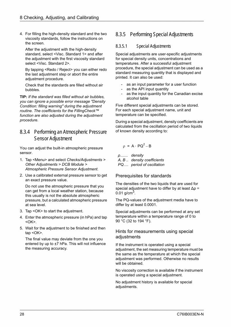
8.3.5 Performing Special Adjustments
8.3.5.1 Special Adjustments
Special adjustments are user-specific adjustments for special density units, concentrations and temperatures. After a successful adjustment procedure, the special adjustment can be used as a standard measuring quantity that is displayed and printed. It can also be used:
- as an input parameter for a user function- as the API input quantity- as the input quantity for the Canadian excise
alcohol table
Five different special adjustments can be stored. For each special adjustment name, unit and temperature can be specified.
During a special adjustment, density coefficients are calculated from the oscillation period of two liquids of known density according to:
Prerequisites for standards
The densities of the two liquids that are used for special adjustment have to differ by at least ∆ρ = 0.01 g/cm3.
The PQ-values of the adjustment media have to differ by at least 0.0001.
Special adjustments can be performed at any set temperature within a temperature range of 0 to 90 °C (32 to 194 °F).
Hints for measurements using special adjustments
If the instrument is operated using a special adjustment, the set measuring temperature must be the same as the temperature at which the special adjustment was performed. Otherwise no results will be obtained.
No viscosity correction is available if the instrument is operated using a special adjustment.
No adjustment history is available for special adjustments.
ρ densityA, B .. density coefficientsPQ .... period of oscillation
A PQ2
B–=
28 C76IB003EN-N

8 Checking, Adjusting, and Calibrating
To perform a special adjustment
1. Tap <Menu> and select Checks/Adjustments > Other Adjustments > Density Module > Special Adjustments.
2. Perform the following settings:
- Use the drop-down box "Adjustments" to select one of the 5 available "Special Adjustment" entries.
- Enter "Name" and "Unit" for the special adjustment.
- Define the "Temperature".
3. Tap <OK> to continue.
The special adjustment routine starts.
4. Rinse the measuring cell.
5. Press the <Air Pump on> button to dry the measuring cell.
6. Fill the first standard into the measuring cell and tap <OK>.
Check that the standard is filled without air bubbles.
7. Enter the reference value for the first standard and tap <OK>.
8. Enter the reference value for the second standard and tap <OK>.
9. Rinse the measuring cell.
10.Press the <Air Pump on> button to dry the measuring cell.
11.Fill the second standard into the measuring cell and tap <OK>.
Check that the standard is filled without air bubbles.
12.Check the recommendation on the screen and select one of the options <Print>, <Reject> or <Apply>.
After successful adjustment, the determined special adjustment coefficients are stored. A new output quantity is generated in the group "Special Adjustments" which is calculated using these coefficients.
TIP: The new output quantity will only calculate valid results in methods using the same set temperature as the previously performed special adjustment.
8.3.5.2 Special Adjustment for the Canadian Excise Alcohol Table
To use the output quantity "Canadian Excise Alcohol Table", see appendix F, it is necessary to perform a special adjustment with apparent density values of air and water and link that adjustment to the Canadian Excise Alcohol Table.
1. Perform a special adjustment with air and water using apparent density for the reference values.
2. Link the special adjustment to the Canadian Excise Alcohol Table, see section 9.2.2.1.
3. Select the table for output fields, result outputs and the data browser.
8.3.6 Viewing, Printing or Exporting Adjustment Data
You can view, print and export the detailed data for the last 50 adjustments both for density and temperature.
To view adjustment data
1. Tap <Menu> and select Data Memory > Adjustment Data > Density Module and select "Density Adjustment", "Special Adjustment" or "Temperature Adjustment" to open the respective adjustment list.
2. To view the adjustment data in detail, highlight the list item and tap <Details>.
To print or export single adjustment data
1. Tap <Menu> and select Data Memory > Adjustment Data > Density Module and select "Density Adjustment", "Special Adjustment" or "Temperature Adjustment" to open the respective adjustment list.
2. To print or export single adjustment data, highlight the list item, tap <Details> and then <Print or Export>.
Use and to scroll the data list.
NOTICEInconsistent adjustment data can be the result of changing the reference tables for air and water, see section 8.3.1.
C76IB003EN-N 29

8 Checking, Adjusting, and Calibrating
To print or export all adjustment data
1. Tap <Menu> and select Data Memory > Adjustment Data > Print or Export Adjustment Data.
2. To perform a printout of all adjustment data on paper or to a PDF file or to export all adjustment data as an MS Excel or Text file, activate the "Density Module" check box and tap <OK>.
8.3.7 Viewing, Printing or Exporting Adjustment History: KB Graph
You can view the KB values for the last 50 adjustments in form of a graph. You can print or export the KB graph together with a list of the KB values.
1. Tap <Menu> and select Data Memory > Adjustment Data > Density Module > Density Adjustment KB Graph.
2. Tap on the graph to activate the zoom function.
- Use the magnifiers below the graph to zoom in and out.
- Use the arrows to move from one data point to the previous or next.
- Use the data point bar to scroll within the graph.
- To close the zoom function, tap <X> in the upper right corner.
3. To perform a printout on paper or to a PDF file, tap <Print or Export> and follow the instructions on the screen.
RS-232 printers with paper roll cannot print the KB graph.
8.3.8 Resetting the Adjustment Data to Factory Adjustment
You can re-activate the factory adjustment for the density measurement.
1. Tap <Menu> and select Checks/Adjustments > Other Adjustments > Density Module > Reset To Factory Adjustment.
2. Activate the "Density Module" check box and tap <OK>.
8.3.9 Adjustment Analysis
The adjustment analysis function is based on an evaluation of the instrument constants which are determined during an adjustment. If the adjustment analysis is activated the instrument will automatically compare the latest adjusted constants to those of the reference adjustment. If the adjustment shows a significant deviation towards the reference adjustment the instrument will generate a warning. Therefore it is important to perform the adjustment procedure properly.
A deviation might be caused by an improper adjustment (e.g. insufficient drying prior to air adjustment, presence of gas bubbles or impurities), removal of cell material due to aggressive liquids or due to built-up deposits in the measuring cell.
TIP: Take a look at the KB-Graph to obtain additional information on the quality of your adjustments. While deposits inside the U-tube are indicated by increasing values, cell removal is indicated by decreasing values.
To activate or deactivate adjustment analysis
1. Tap <Menu> and select “Setup > Measuring System Settings > Density Module”.
2. Activate or deactivate the adjustment analysis functionality.
3. Tap <OK> if the current adjustment should be used as reference adjustment or tap <Set Reference Adjustment> to perform a new reference adjustment.
NOTICEInconsistent adjustment data can be the result of changing the reference tables for air and water, see section 8.3.1.
NOTICEFactory default reference values for the density of air and water are based on the formula of Spieweck and Bettin, see section 8.3.1.
NOTICEFluctuations are most probably caused by variations in the air density due to varying weather conditions. Such fluctuations can be avoided by entering the current barometric pressure before the air adjustment.
NOTICEInconsistent adjustment data can be the result of changing the reference tables for air and water, see section 8.3.1.
30 C76IB003EN-N

8 Checking, Adjusting, and Calibrating
8.4 Calibrating
The goal of a calibration is to validate the accuracy of the density measurement.
To calibrate the instrument, measure a certified standard liquid and compare the result to the reference value indicated in the calibration certificate of the standard.
The physical properties (density, viscosity) of the liquid density standards should be similar to those of the samples.
The frequency of calibrations with certified liquid density standards depends on your requirements and judgment. Recommendation: 1 to 2 calibrations per year.
To perform a calibration
1. Perform a density check with water.
2. If necessary, carry out an air/water adjustment at 20 °C.
3. Thoroughly clean and dry the measuring cell.
4. Select a measuring method that is set to "20 °C" and "Measurement finished by: Equilibrium". For DMA 5000 M, use the setting "Measurement finished by: Equilibrium slow".
5. Open the bottle with the liquid density standard.
TIP: If your bottle with density standard has a septum, we recommend you pierce it carefully with any clean, sharp tool and fill a Luer tip syringe with standard liquid by pushing the tip into the hole of the septum, holding the bottle upside down and slowly pulling the plunger.
6. Immediately after opening the bottle, inject the standard into the DMA M measuring cell.
7. Perform a measurement.
TIP: If you have enough standard liquid, we recommend making a series of three measurements and take the arithmetic average of the results.
8. After the measurement is finished, print the result.
9. Document the calibration procedure in a calibration protocol which contains the operator’s name, date, place, description of the calibration procedure, results and the calibration certificate of the liquid density standard.
NOTICE• Always check the date of expiry of the
calibration liquids. • Store the calibration liquids in a cool and dark
place.• Use the calibration liquids immediately and
only once after the container has been opened.
C76IB003EN-N 31

9 Defining and Using Methods
9 Defining and Using Methods
9.1 Measuring Methods
Each method contains the following kind of information:
- Instrument settings - Xsample settings and measuring module
settings (if any module is installed)- Layout of measuring data on the main
screen- Measuring units- Parameter list for printout and data export
You can use the factory preset methods as they are or change them to suit your needs. You can also create new methods. For these activities, see the General Software Functions Manual, section 7.2 and section 7.3.
Factory preset methods
The DMA M is delivered with a set of 10 predefined methods covering the most common applications.
The measuring temperature for these 10 methods is set to 20 °C.
Fig. 9-1: Example: Measurement with the "Density" method
Density• General purpose method• Output fields: Density, Specific Gravity, Density
Temperature, Density Condition, U-View™
Density (not visc.-corr.)
• General purpose method, for comparison with old instruments without viscosity correction
• Output fields: Density (not visc.-corr.), Specific Gravity (not visc.-corr.), Density Temperature, Density Condition, U-View™
°Brix• For measurements of sugar in soft drinks• Output fields: Concentration Sugar, Density, Density
Temperature, Density Condition, U-View™
Ethanol (% w/w OIML-ITS-90)• For measurements of alcohol concentration in distillates• Output fields: Ethanol OIML-ITS-90 (% w/w), Density,
Density Temperature, Density Condition, U-View™
Ethanol (% v/v OIML-ITS-90)• For measurements of alcohol concentration in distillates• Output fields: Ethanol OIML-ITS-90 (% v/v), Density,
Density Temperature, Density Condition, U-View™
Ethanol (°Proof 60 °F AOAC)• For measurements of alcohol concentration in distillates• Output fields: Ethanol Proof 60 °F, Density, Density
Temperature, Density Condition, U-View™
Crude Oil (API)
• For measurements of crude oil according to calculations for product group A with temperature correction to 15 °C
• Output fields: API Density 15 °C, Density, API Specific Gravity 15 °C, Density Temperature, °API Gravity 15 °C, Density Condition, U-View™
32 C76IB003EN-N

9 Defining and Using Methods
9.2 Changing Methods
You need administrator rights to create, edit or delete methods. The maximum number of methods is 200.
For setting the displayed output fields, result output quantities, limits and quick settings parameters, see the General Software Functions Manual, section 7.2.
9.2.1 Defining the Measurement Settings of the Density Module
For each method, you can set the following measuring parameters for measurements:
• Measurement finished by: The measurement is finished by predetermination or temperature equilibrium (measuring cell temperature = set temperature).
If you select "Predetermination", the instrument finishes the measurement before temperature equilibrium was reached and calculates the density at the set temperature in advance. This saves time but makes the result less accurate.
If you select "Equilibrium", the measurement finishes after temperature equilibrium was established.
DMA 5000 M: With this instrument, you have the choice between "Predetermination", "Equilibrium fast", "Equilibrium medium" and "Equilibrium slow". The slower the equilibrium, the more accurate are the results.
• Temperature: Measuring temperature.
• Timeout: If a measurement is not finished after the specified timeout, it will be aborted. The timeout count starts when temperature equilibrium is reached.
• FillingCheck™: The instrument automatically detects inhomogeneities and gas bubbles in the whole measuring cell by an advanced analysis of its oscillation pattern and generates a warning message in real time for any single measurement.
To define the measurement settings
1. Tap <Menu> and select Methods > Method Settings > method name > Density Module.
2. Select the predetermination/equilibrium type of measurement.
3. Enter the "Temperature".
4. Define the "Timeout".
5. Use the drop-down box "FillingCheck™" to select the preferred option (always active, not active, active during measurement).
6. Tap <OK>.
Fuel Oil (API)
• For measurements of fuel oil according to calculations for product group B with temperature correction to 15 °C
• Output fields: API Density 15 °C, Density, API Specific Gravity 15 °C, Density Temperature, °API Gravity 15 °C, Density Condition, U-View™
Lubricants (API)
• For measurements of lubricants according to calculations for product group D with temperature correction to 15 °C
• Output fields: API Density 15 °C, Density, API Specific Gravity 15 °C, Density Temperature, °API Gravity 15 °C, Density Condition, U-View™
Sulfuric Acid (% w/w)• For measurements of sulfuric acid up to 94 % w/w• Output fields: Sulfuric Acid (H2SO4) (% w/w), Density,
Density Temperature, Density Condition, U-View™
C76IB003EN-N 33

9 Defining and Using Methods
9.2.2 Defining the Measurement Mode
For each method, you can set the measurement mode that will be applied when measuring samples.
TIP: The exported PDF file of measurements in the MM, RM, or MF mode also includes the arithmetic mean and the standard deviation of each multiple measurement series. The standard deviation is calculated according to the following formula:
sd empirical standard deviationn number of measurements in the seriesxi measured value of the ith measurement
"Standard" mode
1. Tap <Menu> and select Methods > Method Settings > method name > Measurement Mode.
2. To select "S (Standard)", highlight the item and tap <OK>.
"Check" mode
Air Check and Water Check are predefined for all methods. User-defined checks are only available with the method that was assigned to the check.
1. Tap <Menu> and select Methods > Method Settings > method name > Measurement Mode.
2. To select "C (Check)", highlight the item and tap <Next>.
3. Select one of the defined checks and tap <OK>.
"Multiple Measurements" mode
Using multiple measurements enables you to perform several measurements automatically. A single entry in the sample list starts a series of up to 10 measurements of a sample and calculates the average values of these measurements.
Multiple measurements create additional entries in the data memory as not only the single measurements but also the average values are calculated and stored.
1. Tap <Menu> and select Methods > Method Settings > method name > Measurement Mode.
2. To select "MM (Multiple Measurements)", highlight the item and tap <Next>.
3. Select the number of multiple measurement cycles and tap <OK>.
Table 9-1: Measurement modes
S (Standard) To perform a standard measurement
C (Check) To perform one of the predefined checks.
MM (Multiple Measurements) To perform 2 to 10 measurements of a single sample automatically.
RM (Repeated Mode) To perform repeated measurements of a single sample by filling the sample up to 5 times and defining a maximum deviation of two subsequent measurements.
MF (Multiple Filling) To perform multiple measurements of a single sample by filling the sample 2 to 5 times.
TS (Temperature Scan) To perform a temperature scan.
TTS (Temperature Table Scan) To perform a temperature table scan.
sdn xi
2 i 1=
n
xii 1=
n
2
–
n n 1– ----------------------------------------------------------------------------=
NOTICEIf multiple measurements are activated for a certain method, it is no longer possible to define a temperature scan for the specific method in the sample list.
34 C76IB003EN-N

9 Defining and Using Methods
"Repeated Mode"
Using repeated mode enables you to perform up to 5 filling procedures and subsequent measurements of the same sample.
The density deviation between two subsequent measurements is calculated and compared with a defined value. When the deviation is smaller than the defined value, the measurement results are valid and no further measurements are performed.
You can save all measurements, only the valid two measurements or the final measurement only. If the deviation of all measurements is too high, the density value of each sub measurement as well as an average value will be saved.
To view and save the deviation between two valid measurements, select the output quantity "Repeat Deviation Density" for the display layout and result output.
Allowed density deviation values
The default value of the density deviation depends on the type of equilibrium (Measurement finished by) of the density module (see the table below).
To set the repeated mode
1. Tap <Menu> and select Methods > Method Settings > method name > Measurement Mode.
2. To select "RM (Repeated Mode)", highlight the item and tap <OK>.
3. Tap "Repeated Mode Settings".
4. Select the maximum number of determinations (up to 5).
5. Select the "Save Mode" (all, valid two only or final one only).
6. Tap <Next>.
7. Activate the quantity to be used for the determinations.
8. Use the default value for the selected quantity, or disable the "Use Default" check box and enter the maximum repeat value as desired.
9. Tap <OK>.
"Multiple Filling" mode
Using multiple filling enables you to perform measurements of a single sample by refilling the sample up to 5 times. If multiple filling measurement is performed, an additional entry in the data memory is created as not only the single measurements but also the average value is calculated and stored.
1. Tap <Menu> and select Methods > Method Settings > method name > Measurement Mode.
2. To select "MF (Multiple Filling)", highlight the item and tap <Next>.
3. Use the "Multiple filling" drop-down box to select the number of measurements (up to 5).
4. Tap <OK>.
"Temperature Scan" mode
Using temperature scan measurements enables you to perform measurements of a sample at several temperatures that are defined by intervals in a set temperature range. Temperatures from 0 °C to 95 °C are allowed.
Make sure to set the temperature step interval so that the instrument can reach the end temperature by a whole number of steps (divide the interval between start and end temperature by whole numbers only to find appropriate step settings).
The minimum step size in temperature scans depends on the defined type of equilibrium (Measurement finished by) of the density module:
Deviation (g/cm3)
DMA 4100 M
DMA 4500 M
DMA 5000 M
Minimum 0.0001 0.00001 0.000001
Maximum 0.001 0.001 0.001
Deviation (g/cm3)
Type of equilibrium
DMA 4100 M
DMA 4500 M
DMA 5000 M
Predetermined 0.0003 0.00005 0.000005
Equilibrium 0.0001 0.00001 -
Equilibrium fast
- - 0.000003
Equilibrium medium
- - 0.000002
Equilibrium slow
- - 0.000001
Measurement finished by
Min. step size
Model
Predetermined 1 °C all models
Equilibrium 0.02 °C DMA 4100 M DMA 4500 M
• Equilibrium fast• Equilibrium medium• Equilibrium slow
0.02 °C0.01 °C0.005 °C
DMA 5000 M
C76IB003EN-N 35

9 Defining and Using Methods
1. Tap <Menu> and select Methods > Method Settings > method name >Measurement Mode.
2. To select "TS (Temperature Scan)", highlight the item and tap <Next>.
3. Enter the "Start", "Step" and "End" temperature of the temperature scan.
The start temperature has to be higher than the end temperature to prevent degassing in the measuring cell.
4. Tap <OK>.
"Temperature Table Scan" mode
Using temperature table scan measurements enables you to perform measurements of a sample at several defined temperatures. Temperatures from 0 °C to 95 °C are allowed.
For the minimum difference between two consecutive temperatures, see the table listing the minimum step sizes for the temperature scan mode.
1. Tap <Menu> and select Methods > Method Settings > method name > Measurement Mode.
2. To select "TTS (Temperature Table Scan)", highlight the item and tap <Next>.
3. Enter the desired temperatures in the table and tap <OK> after each entry.
The start temperature has to be higher than the end temperature to prevent degassing in the measuring cell.
4. Tap <OK> to save the settings.
9.2.2.1 Defining Formula Parameters
You can enter formula parameters to define how API parameters shall be determined and to define which special adjustment shall be used for the Canadian excise alcohol table.
Parameter "Density API Input Quantity"
API parameters are usually calculated based on true density; the input quantity can be defined as:
- Density (not visc.-corr.)- Density- Special Adjustment 1, ..., 5
Parameter "Density API Product Group"
The API Product Group can be set to A (crude oil), B (fuels) or D (lubes) to set up measuring methods for different product groups. You can also define a API Product Group of your own (Custom) for special applications.
The conversion formulas from input quantities (Density etc.) to API quantities differ between the product groups and therefore need to be defined for the measuring methods.
Parameter " Density API Alpha Factor"
For liquids that are assigned to the special applications category a specific thermal expansion factor has to be established for each particular fluid.
Parameter "Density Canadian Excise Alcohol Table"
The input quantity for the Canadian Excise Alcohol Table can be defined as:
- Special Adjustment 1, ..., 5 see section 8.3.5.2
To define formula parameters
1. Tap <Menu> and select Methods > Method Settings > method name > Formula Parameters.
2. Select an API Product Group and API Input Quantity.
3. Select the special adjustment for the Canadian Excise Alcohol Table.
4. Tap <OK>.
TIP: Before you use the output quantity "Canadian Excise Alcohol Table" of the group "Ethanol Tables", see appendix F, it is necessary to perform a special adjustment with apparent density values of air and water, see section 8.3.5.2, and link that adjustment to the Canadian Excise Alcohol Table, see section 9.2.2.1.
36 C76IB003EN-N

10 Measuring
10 MeasuringIn this chapter, the filling of samples and the measuring procedure including the detection of bubbles are described.
10.1 Sample Name
If you have defined automatic sample name parts, see General Software Functions Manual, section 6.3, they will be added to each sample name after measurement has been finished.
The complete sample name, including automatic sample name parts, may consist of up to 50 characters.
10.2 Filling Samples
To achieve highly accurate measuring results, fill the samples into the measuring cell homogeneously and without bubbles.
WARNING
In the unlikely case of malfunction or damage of the Peltier elements, the heating control of the measuring cell is affected, and the measuring cell’s temperature might rise up to 150 °C (302 °F). Liquids can then spurt out of the measuring cell and potentially cause injuries or fire.To avoid injuries and fire:• Ensure that the waste vessel is properly
installed.• Use method settings that constantly display
the measuring cell’s temperature.• Check the cell temperature before filling a
sample or starting a measurement.• Use only the smallest possible sample amount
if you measure aggressive, toxic, or flammable samples.
• If your sample is toxic or highly flammable, always handle it in an appropriate environment, e.g. under a fume hood, and ensure that the location is sufficiently ventilated.
• Measure only samples with an ignition point over 150 °C.
• Wear protective clothing and safety goggles.
WARNING
Filling samples and cleaning liquids which the wetted parts are not resistant to will corrode the wetted parts. Sample leaking from corroded parts may cause serious injuries. Before filling any sample or cleaning liquid into your DMA M:• make sure that all safety instructions
concerning the use of chemicals and the use of flammable chemicals are met, see section 2.
• make sure all wetted parts are resistant to the filled-in liquid (see appendix A.3).
• make sure that you have suitable cleaning fluids at hand for cleaning the measuring cell, see section 11.1.
• If a sample changer is connected, check the resistance of the wetted parts. For information about the materials, see the corresponding instruction manual of the sample changer.
NOTICESamples with a moderate tendency to corrode borosilicate glass such as strong alkali solutions (e.g. caustic soda) can be measured with the DMA M.• However, take care to remove such samples
immediately after measurement and rinse the measuring cells properly.
• Check the validity of the adjustment more frequently than generally recommended.
• Perform a new adjustment, if necessary.• The measuring temperature for strong alkali
solutions should not be higher than 20 °C. Higher temperatures dramatically increase the speed of corrosion.
C76IB003EN-N 37

10 Measuring
Important for high accuracy measurements
If you use a syringe to fill the instrument, we recommend using a 2 mL syringe only to fully utilize the instrument’s accuracy (especially with DMA 5000 M). Inject the entire sample volume. The syringe can stay connected to the filling adapter during the measurement.
If you use syringes with higher volumes, carefully disconnect the syringe from the filling adapter after filling the sample. Otherwise, errors due to the weight of the syringe are possible.
Make sure to apply exactly the same filling procedure for checks, adjustments and measurements.
Sample amount
If the measuring cell is clean and dry, you need approx. 1 mL of sample.
If you are measuring without cleaning and drying between the samples, you need a higher amount of sample because you have to flush residues of the previous sample out of the measuring cell to avoid cross-contamination.
Bubble detection using the camera – U-View™
1. Tap in the quick access area to open the live camera view of the measuring cell.
2. Tap <Zoom In> to get a magnified view.
3. Attach a USB flash drive and tap <Save Picture> to save the current picture.
4. Tap <X> to exit the measuring cell view.
Fig. 10-1: Camera window
To fill with a syringe (Luer tip)
Fig. 10-2: Filling with a syringe
1. Connect the syringe to the sample inlet adapter.
2. Push the plunger of the syringe slowly and continuously until a drop emerges from the sample outlet adapter.
3. Leave the syringe in the filling position during the measurement.
To fill with a funnel
1. Mount an adapter Luer cone to the sample inlet adapter.
2. Connect the adapter with a funnel using a silicone hose (3x5 mm).
3. Fix the funnel in a position higher than the sample inlet of the DMA M.
4. On the outlet of the DMA M, mount another adapter Luer cone and connect it to a waste vessel using a second silicone hose (3x5 mm).
5. Mount a valve or hose clamp at the outlet silicone hose.
6. Close the valve and fill your sample into the funnel.
7. Fill the measuring cell by carefully opening the valve and closing it again before the funnel runs empty.
NOTICEDo not use syringes that contain lubricants. The lubricants can dissolve into your sample and lead to a systematic measuring error.
38 C76IB003EN-N

10 Measuring
To fill with a peristaltic pump
1. Mount an adapter Luer cone to the sample inlet adapter.
2. Connect the adapter Luer cone with the sample container using a silicone hose (3x5 mm).
3. Mount an adapter Luer cone to the sample outlet adapter.
4. Connect a silicone hose (3x5 mm) to the adapter Luer cone and lead the silicone hose via the peristaltic pump to a waste vessel.
5. Set the flow rate to 10 to 25 mL per minute.
6. Start the pump.
7. Turn off the pump after filling a sufficient amount of sample.
To fill automatically with an Xsample
For details, see the respective Xsample instruction manual.
10.3 Performing Measurements
To speed up measurements
Automatic sample naming: See General Software Functions Manual, section 6.3.
Prethermostatting: Prethermostat your samples to the measuring temperature before injection to reduce the time necessary for the temperature equilibration.
Predetermination option: Using this option reduces the measuring time substantially, see section 9.2.1.
To perform a measurement
1. Before starting a measurement, check if:
- the measuring cell is clean and dry- the hoses are connected correctly- the hose connections are tight- the waste hose leads into the waste
container- the waste container’s volume is large enough
for the number of samples- the correct sample names are entered- the method settings are set correctly- suitable cleaning liquids are available.
2. Fill the measuring cell with sample.
3. Enter a sample name if required.
4. Tap <Start> and wait until the measurement is finished.
The progress bar shows the progress of the measurement with a growing red bar and the message "Measuring".
During measurements, the last 1, 2 or 3 digits might be grayed signifying that the set temperature has not been reached yet. In this case, only the solid black digits are valid. The number of valid (black) digits will increase during measurement progress until all digits are black (when using equilibrium mode).
When the measurement is finished, the progress bar turns green, the message "Finished" is displayed and an acoustic signal is given. The "Density Condition" output field shows the message "valid".
The result values are frozen. The display can be unfrozen by tapping .
The result values are saved in the data memory and can be viewed, printed, exported or deleted.
NOTICE• The liquid levels in the sample container and
waste container must be below the filling level of the instrument. Never put the peristaltic pump or waste container on top of the instrument.
• Check the hoses of the peristaltic pump daily.• Check the life time of the hoses specified by
the supplier and change the hose frequently.
C76IB003EN-N 39

10 Measuring
10.4 Filling and Measurement Errors
10.4.1 Status Messages
Density condition
The "Density Condition" output field gives information about the current status of measurement and may show the following messages:
Sample status icons
In the first column of the sample list, you find an icon for each sample that has already been measured. The icon indicates the status of the sample:
10.4.2 Error Messages
Automatic bubble detection (FillingCheck™)
If a bubble has been detected anywhere in the U-tube in real time, the "Density Condition" output field shows "Filling Warning" or "Error: No Oscillation" for the current sample and the message list quick access button changes: Instead of the green OK mark, the yellow warning sign is displayed.
Note: For complete transparency and traceability of your sample filling and measurement process, check the filling visually by means of the built-in camera (U-View™) in addition to the fully automatic FillingCheck™.
TIP: FillingCheck™ provides excellent support to the operator for samples of low and medium viscosity ranges. Highly viscous samples above 3000 mPa·s, which firmly enclose contained air bubbles, might not be analyzed correctly and generate a filling warning even if filled without bubbles.
Message list window
The appearance of the message list button in the quick access area indicates the current error status, see the section "Quick access buttons" in section 6.4. Tapping the button opens the message list window where the general status of the DMA M and the measuring errors that occurred are displayed.
temp.equilibration
Appears during temperature equilibration. In this stage no predetermined result can be determined by the instrument.
pre-determined
Appears before the exact measuring temperature has been reached and the instrument can determine a predetermined result.
valid Appears when the measuring temperature has been reached and the measurement has been taken.
The sample was successfully measured.
Reduced precision due to e.g. a filling
error.
No result due to a malfunction.
The measurement was canceled.
40 C76IB003EN-N

11 Cleaning and Storing the Instrument
11 Cleaning and Storing the InstrumentTo assure a constant and high accuracy of your measurements, employ a regular and effective cleaning routine, and store the instrument under the recommended conditions.
11.1 Cleaning and Drying the Measuring Cell
Cleaning frequency
Clean and dry the measuring cell at least after each working day or working shift.
Cleaning more frequently can be necessary...
- when you perform adjustments- when you measure a sample that is not
miscible with the previous sample (e.g., water after a petrochemical sample)
- when you want to measure using a minimum sample amount
- when you measure a sample that could chemically react with the previous sample
Cleaning liquids
For cleaning and drying, employ two cleaning liquids:
- Cleaning liquid 1 dissolves and removes sample residues in the measuring cell. It has to be a good solvent for all sample components.
- Cleaning liquid 2 removes cleaning liquid 1 and is easily evaporated by a stream of dry air in order to accelerate drying of the cell. Cleaning liquid 2 has to be a good solvent for cleaning liquid 1.
Recommended for aqueous samples and beverages: water (cleaning liquid 1) and non-denatured ethanol (cleaning liquid 2).
Recommended for petrochemical samples: petroleum naphtha (cleaning liquid 1) and acetone (cleaning liquid 2).
If you are not sure if a cleaning liquid is suitable for your sample, perform a preliminary test in a test tube to see if any phase separation, precipitate or opalescence can be observed.
To perform a cleaning and drying procedure without Xsample filling equipment
1. Rinse the measuring cell with cleaning liquid 1 (minimum 5 mL).
If your sample is viscous or contains particles, use more cleaning liquid.
2. Empty the measuring cell.
3. Rinse the measuring cell with cleaning liquid 2 (minimum 5 mL).
4. Empty the measuring cell.
5. Insert the air pump hose with the adapter Luer cone into one of the injection adapters.
Fig. 11-1: Drying the measuring cell
6. Tap in the quick access area to start the air pump.
7. Wait until the measuring cell is dry (stable density reading).
WARNING
Liquids leaking from the instrument may lead to injuries and risk of fire.Before filling any sample or cleaning liquid into your DMA M, make sure that:• all safety instructions concerning the use of
chemicals and the use of flammable chemicals are met, see section 2.
• all wetted parts are resistant, see appendix A.3.
NOTICEDo not use any mechanical action for cleaning the measuring cell.
C76IB003EN-N 41

11 Cleaning and Storing the Instrument
The time needed depends on the vapor pressure of your cleaning liquid 2 and the temperature of the measuring cell (Ethanol at 20 °C: approx. 5 min., Acetone at 20 °C: approx. 3 min.).
If the ambient humidity is > 90 % relative humidity, use a drying cartridge, see appendix C.1, to reduce the drying time.
8. Tap in the quick access area to stop the air pump, or wait for the pump time out.
To perform a cleaning and drying procedure with Xsample filling equipment
For details, see the respective Xsample instruction manual.
11.2 Storing the Instrument
Clean and dry the measuring cell, see section 11.1, before storing the instrument for more than one day. Otherwise, algae may grow on the glass surface that are difficult to remove.
For storage for less than one day, the measuring cell can be filled with ultra-pure (bi-distilled or deionized) water or the last cleaning liquid that has been injected. In case of syringe injection, leave the syringe mounted to the injection adapter to prevent spillage of the liquid.
11.3 Cleaning the Instrument Housing and Touch Screen
To clean the instrument housing or the touch screen, use a soft tissue that can be wetted with ethanol or warm water, if necessary with some mild cleaning agent added (pH < 10).
11.4 Repair
In case your instrument needs repair, contact your local Anton Paar representative who will take care of the necessary steps. The instrument must not be returned without the filled out "Safety Declaration for Instrument Repairs" and must be cleaned before return.
TIP: Find the contact data of your local Anton Paar representative on the Anton Paar website (http://www.anton-paar.com) under "Contact".
WARNING
Ethanol is a highly flammable liquid.• Make sure that all safety instructions regarding
the use of flammable liquids, see section 2, are strictly followed.
NOTICEUsing substances for cleaning which are not suitable causes corrosion of the instrument housing. Never use:• highly nonpolar solvents (e.g. toluene, hexane,
solvent naphtha)• strong acids or bases (e.g. nitric acid, sulfuric
acid, hydrochloric acid, caustic soda)• strong mechanical action (steel brush).
42 C76IB003EN-N

Appendix A: Technical Data
Appendix A: Technical Data
A.1: Measuring PerformanceTable A-1: Technical data of measuring performance
DMA 4100 M DMA 4500 M DMA 5000 M
Measuring range 0 to 3 g/cm3
Repeatability density (s. d.) 0.00005 g/cm3 0.00001 g/cm3 0.000001 g/cm3
Repeatability temperature (s. d.)a
a Repeatability may be expressed with the repeatability standard deviation. This standard deviation is calculated from measurements carried out under repeatability conditions.
0.02 °C 0.01 °C 0.001 °C
Measuring timeb
b After full temperature equilibrium
approx. 30 sec approx. 30 sec approx. 40 sec
Measuring temperaturec
c Cooling down further than 20 °C (68 °F) below ambient temperature only with external cooling using the cooling kit
0 °C to 95 °C (32 to 203 °F)d
d Below DCB version 1.000.009: 0–90 °C (32–194 °F)
Pressure rangee
e For the measuring cell together with the injection adapters DMA/CarboQC (Mat. No. 159537) in the temperature range of 0–50 °C (32–122 °F). For temperatures above 50 °C (122 °F), the maximum allowed pressure is 5 bar (72.5 psi) absolute pressure. See also appendix C.2.
0 to 10 bar (14.5 to 145 psi) absolute pressure
Sample volume approx. 1 mL
Ambient air pressure sensor yes
Full range viscosity correction yes
Reference oscillator yes
Automatic bubble detection yes
Visual check of the measuring cell Camera
Table A-2: Typical accuracya of concentration measurements (aqueous solutions, % w/w)
a The accuracy is not the same over the whole concentration range. The values given are typical values for orientation purposes.
DMA 4100 M DMA 4500 M DMA 5000 M
Ethanol 0.05 0.025b
b In the temperature range of 15–25 °C (59–77 °F) the accuracy is 0.01 % w/w.
< 0.01
Extract/Sugar 0.025 0.015 < 0.01
HCl 0.02 0.01 < 0.01
NaOH 0.04 0.02 < 0.01
H3PO4 0.06 0.03 < 0.01
HNO3 0.07 0.035 < 0.01
H2SO4 0.05 0.025 < 0.01
C76IB003EN-N 43

Appendix A: Technical Data
A.2: General Technical Data
Dimensions (L x W x H) 495 mm x 330 mm x 230 mm(19.5 in x 13 in x 9 in)
Weight 22.5 kg (49.6 lbs)
Voltage AC 100 to 240 V, 50/60 Hz
Power 190 VA (incl. Xsample and external measuring module)
Power inlet according to IEC/EN 60320-1/C14, protection class I
Fuses Glass tube fuses 5 x 20 mm; IEC60127-2; AC 250 V; T 5 AH
Housing material
Top & side cover Aluminum, coated
Back Aluminum
Front Styrene/Butadiene
Environmental conditions (EN 61010)
Indoor use only
Ambient temperature 15–35 °C (59–95 °F)
Air humidity 10–90 % relative humidity, non-condensing
Pollution degree 2
Overvoltage category II
Altitude max. 3000 m (9800 ft)
Touch screen 10.4 ″ TFT PCAP touch screen 640 x 480 px
Memory 1000 measuring values with/without camera pictures
Interfaces 4 x USB (2.0 full speed), 2 x S-Bus, 1 x Ethernet (100 Mbit), 1 x CAN Bus, 1 x RS-232, 1 x VGA
RS-232 printer settings Interface: RS-232 C;Baud rate: 9600; Parity: none; Stop bit: 1; Data bits: 8
WARNING
Serious injuries are possible through high voltage if the following instructions are not adhered to.• Only connect devices to the interfaces that comply with PELV (protective
extra-low voltage) according to EN 61140 or with SELV (safety extra-low voltage) according to EN 60950.
NOTICEConnect only Anton Paar equipment or equipment with a maximum power consumption of 40 W to the CAN interface. Otherwise, the instrument will not work.
44 C76IB003EN-N

Appendix A: Technical Data
A.3: Wetted Parts
The following materials are in contact with samples and cleaning liquids:
DMA M
Standard accessories
Material Part
Borosilicate glass Measuring cell
PTFE Filling adapter
Material Part
Polyethylene Waste vessel
Polypropylene/Polyethylene Syringe 2 mL Luer
PTFE Injection adapter Luer
PTFE Male Luer plug PTFE
PTFE Adapter Luer cone
ETFE Adapter UNF 1/4" Luer male
Silicone Hose 3x5 mm silicone
C76IB003EN-N 45

Appendix B: Measuring Special Samples
Appendix B: Measuring Special Samples
B.1: Degassing Samples
There are different methods to degas liquid samples. The preferable method for your application depends on the kind of sample and the amount of gas that is dissolved in the sample. Pay attention to always treat all samples in the same way in order to get reproducible measuring results.
Be aware of the fact that the composition of some samples may slightly change during the pretreatment due to evaporation of volatile components.
To boil the sample
1. Boil the liquid for several minutes to remove dissolved air.
2. Fill the boiled liquid into a clean glass flask and cover it.
3. Wait until the liquid has cooled down approximately to measuring temperature.
To stir the sample
• Stir your sample vigorously for 2–15 minutes (depending on the stirring equipment) until bubbling ceases.
• You can pour the sample through a paper filter after stirring to degas it even more efficiently.
To use an ultrasonic bath
• Put your sample for approx. 5–10 minutes into an ultrasonic bath until bubbling ceases.
B.2: Special Filling Techniques
Bubbling samples
If the sample to be measured tends to form gas bubbles, degas it before the measurement, see appendix B.1.
If this is not possible, introduce the sample at a temperature higher than the measuring temperature.
You can also put the density meter at a slight angle by means of proper spacers below the right side of the DMA M to allow the bubbles to escape due to buoyancy.
Suspensions and emulsions
Suspensions or emulsions may tend to separate in the measuring cells, giving incorrect results. Leave such samples in the measuring cell as briefly as possible. Prethermostat them before filling.
It may help to put spacers below the left legs of DMA M, thus putting it at an angle to counterbalance the separation force generated by the oscillation of the measuring cell.
Highly viscous samples
Highly viscous samples can be heated up to lower the viscosity. Always heat the sample to a temperature that is approx. 15 °C higher than the measuring temperature, which can be 95 °C maximum.
Pastes
Paste-like materials like toothpaste or tomato ketchup can be filled by syringe. Inject these kinds of samples into the measuring cell by pushing the plunger very slowly and continuously.
If the samples have a very high viscosity, you can fill them into the syringe by pulling the plunger completely out of the syringe, filling it from the back using a spoon and then mounting the plunger again.
WARNING
Samples containing toxic volatile compounds can cause irritation and serious injuries to your eyes, skin and mucous membranes, as well as toxication.• If your sample contains volatile compounds
that are toxic, always handle it in an appropriate environment like under a fume hood, especially when you boil your sample.
WARNING
When you boil flammable liquids, there is the risk of fire. Serious injuries are possible.• Do not boil flammable liquids.
46 C76IB003EN-N

Appendix B: Measuring Special Samples
Liquids in aerosol cans
For the quality control of aerosol cans, you can use the Anton Paar Aerosol Adapter (Mat. No. 74650) to fill the liquid safely and conveniently into your DMA M. For details, see the Aerosol Adapter instruction manual.
Gases
It is possible to measure gases with the DMA M. For details, contact your local Anton Paar representative and ask for the respective application report and the necessary accessories.
C76IB003EN-N 47

Appendix C: Measuring under Special Conditions
Appendix C: Measuring under Special Conditions
C.1: Measuring at High Humidity/Low Temperature Conditions
If the ambient air contains humidity and the measuring temperature is lower than the ambient temperature, condensation may occur in the measuring cell and measuring cell block.
Condensation in the measuring cell causes adjustment and measurement errors in DMA M series instruments and also in any RXA series instruments connected to them. Condensation in the measuring cell block damages the electronics and may lead to a failure of the U-view™ function. The higher the difference between the set measuring temperature and ambient temperature and the higher the air humidity, the easier condensation occurs.
To prevent condensation in the measuring cell
To prevent condensation in the measuring cell, use a drying cartridge (Mat. No. 65085) and connect it to the "DRY AIR IN AIR PUMP" connector at the rear of DMA M, see Fig. C - 1.
Fig. C - 1Drying cartridge connected
For a measuring temperature of 20 °C, a drying cartridge must be used under the following conditions:
To prevent condensation in the measuring cell block
To prevent condensation in the measuring cell block, connect a dry air supply to the "DRY AIR IN BLOCK" connector at the rear of DMA M using a 3x5 mm hose made of suitable material (e.g. silicone) (see Fig. C - 1).
The dry air supply must be used additionally to the drying cartridge if the measuring temperature is more than 5 °C lower than the ambient temperature. The following specifications of the applied air are required:
- 0.2–0.3 bar rel. (2.9–4.4 psi)- Class 5 from ISO 8573-1- Max. particle size: 40 µm- Max. pressure dew point: 10 °C below
measuring temperature- Max. oil content: 25 mg/m3
To regenerate moist silica gel
The drying cartridge contains silica gel, a non-toxic drying agent. When active, the color of the drying agent is orange. Silica gel which has absorbed liquid turns green.
NOTICE• Never connect hoses containing liquids or
moist gases to the "DRY AIR IN AIR PUMP" connector as this may lead to condensation in the measuring cell and subsequently to measurement and adjustment errors.
• Operate the "DRY AIR IN AIR PUMP" connector only at ambient pressure.
Drying cartridge
DRY AIR INAIR PUMP
DRY AIR INBLOCK
Ambient temperatureRelative air humidity
(r. h.)
20 °C > 70 %
25 °C > 50 %
30 °C > 38 %
NOTICENever connect hoses containing liquids or moist gases to the "DRY AIR IN BLOCK" connector as this may lead to damage of the electronics.
48 C76IB003EN-N

Appendix C: Measuring under Special Conditions
Moist silica gel can be regenerated: Pour the silica gel into a glass bowl and blow hot, dry air (max. 130 °C / 266 °F) through it for approx. 5 hours or place it in a laboratory oven for a few hours (or overnight) until it is orange again.
C.2: Measuring at Low/High Temperatures
To measure at low temperatures
To perform measurements at temperatures lower than 20 °C (36 °F) below ambient temperature, install the cooling kit (Mat. No. 80810) and connect the DMA M to an external thermostat. If your tap water is cool enough also connecting to a tap water supply will help. Operate the cooling kit with a moderate flow of water (1–3 liters per minute).
Example: Your ambient temperature is 25 °C (77 °F), and you want to perform measurements at 0 °C (32 °F). Install the cooling kit and connect the
DMA M to an external thermostat or tap water line that is delivering water at a constant temperature between 5 °C and 15 °C (41–59 °F) and change the measuring temperature to 0 °C (32 °F) in the "Density Module" dialog.
To measure at high temperatures
To prevent bubble formation
If you are measuring samples at temperatures significantly higher than ambient temperature, the tendency to form gas bubbles in the measuring cell will dramatically increase. To ensure precise results, you can:
• Degas your samples thoroughly directly before measuring, see appendix B.1.
• Heat your samples up to a temperature significantly higher than the measuring temperature with stirring, directly before measuring.
To measure highly viscous samples at high temperatures
See appendix B.2.
NOTICEDo not use higher drying temperatures than 130 °C (266 °F). Otherwise the indicator function of the silica gel will be spoiled.
Temperature range of the cooling unit
5–30 °C (41–86 °F)
Maximum pressure
1 bar rel. (14.5 psi). For more details, see the cooling kit brief instructions.
Connector
Self-locking coupling 8 mm, Type Rectus 21KBTS08MVN, Mat. No. 75090
WARNING
Risk of leakage!At high sample temperatures in combination with high pressure the injection adapter Luer may leak.• At measuring temperatures of 50 °C (122 °F)
and higher, the applied pressure must be limited to 5 bar (72.5 psi) absolute pressure.
C76IB003EN-N 49

Appendix C: Measuring under Special Conditions
C.3: Measuring at High Pressures
The supplied silicone hose and injection adapters can only be used at atmospheric pressure. Before applying high pressures, exchange the supplied filling components with pressure-resistant components.
Adjustment with air and water
To reach the highest possible accuracy for high pressure measurements, perform the air adjustment as usual at ambient pressure and the water adjustment or an adjustment with any other reference liquid at the pressure at which you are going to perform the measurements.
WARNING
Leaky components of the measuring system can cause sample to be splashed out when pressure is applied to the measuring system. Injuries and risk of fire possible.To avoid injuries, do the following:• At pressures higher than ambient pressure,
only use the injection adapters DMA/CarboQC (Mat. No. 159537) and polyurethane hoses 2.5x4 mm (Mat. No. 15272),
• Before starting a measurement at high pressure, check the pressure tightness of the system with air.
• If you are measuring any aggressive, poisonous or flammable sample at high pressure, only use the smallest possible sample amount.
50 C76IB003EN-N
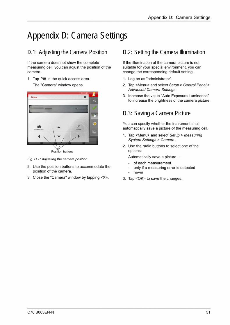
Appendix D: Camera Settings
Appendix D: Camera Settings
D.1: Adjusting the Camera Position
If the camera does not show the complete measuring cell, you can adjust the position of the camera.
1. Tap in the quick access area.
The "Camera" window opens.
Fig. D - 1Adjusting the camera position
2. Use the position buttons to accommodate the position of the camera.
3. Close the "Camera" window by tapping <X>.
D.2: Setting the Camera Illumination
If the illumination of the camera picture is not suitable for your special environment, you can change the corresponding default setting.
1. Log on as "administrator".
2. Tap <Menu> and select Setup > Control Panel > Advanced Camera Settings.
3. Increase the value "Auto Exposure Luminance" to increase the brightness of the camera picture.
D.3: Saving a Camera Picture
You can specify whether the instrument shall automatically save a picture of the measuring cell.
1. Tap <Menu> and select Setup > Measuring System Settings > Camera.
2. Use the radio buttons to select one of the options:
Automatically save a picture ...
- of each measurement- only if a measuring error is detected- never
3. Tap <OK> to save the changes.
Position buttons
C76IB003EN-N 51

Appendix E: Trouble Shooting
Appendix E: Trouble ShootingTable E-1: Adjustment
Problem Cause and Correction See
Readjustment is necessary very often.
Bad water quality for checks/adjustments: Use freshly degassed ultra-pure (bi-distilled or deionized) water.
section 8.3.1
The measuring cell is not clean: Clean and dry the measuring cell perfectly before an air check/adjust-ment.
section 11
The measuring cell is corroded by hydrofluoric acid, strong alkaline solutions or mechanical abrasion: Do not leave glass-corroding liquids in the measuring cell.
section 11
Direct sunlight on the DMA: Install the DMA M at a place without direct sunlight.
section 7.1
The adjustment is not finished after 10 minutes.
The measuring cell is not sufficiently dry for the air adjustment: Clean and dry the measuring cell perfectly before an air check/adjustment.
section 11
There are gas bubbles in the measuring cell during water adjustment: Repeat the filling procedure and use freshly degassed ultra-pure (bi-distilled or deionized) water.
section 8.3.1
Table E-2: Measurement
Problem Cause and Correction See
I cannot start any measure-ment 15 minutes or more after booting the instrument.
Verify whether one or more modules are using older firmware versions than expected from the instrument’s software. This information is either displayed on the start screen or in the message list of the quick access area. Tap <Menu> and select Service > Update > Module Firmware Update to update the respective modules using the internal firmware update package.
General Software Functions Manual, section 10.4
Density Condition: "Filling Warning"
Gas bubbles in the measuring cell: Degas your sample. Fill the sample at higher temperature than the measuring temperature.
appendix B.1
Density Condition: "Error: No Oscillation"
The measuring cell is only partly filled: Fill the sample again.
Density Condition: "Timeout Error"
The sample is instable (e.g. emulsion): Prethermostat your sample.
appendix B.2
The timeout is set too short: Change the timeout setting.
section 9.2.1
The calibration failed. The results deviate from reference values.
Bad cleaning and drying: Improve your cleaning and drying procedure.
section 11.1
The calibration liquid was stored too long: Use a fresh calibration liquid.
Adjustment problems: Improve your adjustment routine.
section 8.3.1
52 C76IB003EN-N

Appendix E: Trouble Shooting
The measuring times during a temperature scan are varying.
The measuring times during temperature scans can vary due to internal temperature measurements and calibration after changing the temperature by a defined value.
Table E-3: Touch screen
Problem Cause and Correction See
The screen flickers. Due to manufacturing tolerances of the hardware, the screen may flicker for certain values of reduced display brightness. Change the display brightness.
General Software Functions Manual, section 4.4
Table E-4: Data memory
Problem Cause and Correction See
I cannot see certain results in the data memory.
The filter function is activated and the results do not match the filter criteria: Change the filter settings.
General Software Functions Manual, section 8.4
I have deleted all results but there are still results visible in the data memory.
The filter settings in the "Delete Measured Data" menu are different from the settings in the "Data Browser Settings" menu: Perform corresponding settings in both menus.
General Software Functions Manual, section 8.7, section 8.4
Table E-5: Data export
Problem Cause and Correction See
The export to the USB flash drive does not work.
The USB flash drive has the old super floppy formatting and is therefore not accepted by the instrument: Reformat to hard disk type or try a newer USB flash drive.
Wrong output data are exported.
The settings in the "Result Output" menu are wrong: Change the settings.
General Software Functions Manual, section 7.2.2
Table E-6: Password protection
Problem Cause and Correction See
The instrument boots up
without logon procedure and
no password is requested.
A user with activated auto logon function has been
logged in on the instrument before it was switched off:
Tap on the user indicator icon and log in with another
user account.
General
Software
Functions
Manual,
section 6.5.1
Table E-2: Measurement
Problem Cause and Correction See
C76IB003EN-N 53

Appendix E: Trouble Shooting
Table E-7: Printout problems
Problem Cause and Correction See
No printout on office printer Office printer problems: Check if the printer has enough paper, toner, etc. See the respective printer instruction manual.
The office printer type is not supported by your instrument.
General Software Functions Manual, section 5.3
Wrong interface used: Use the interface which was defined in the "Printer Management" menu or change the interface settings.
Wrong or no definition of the printer in the "Printer Management" menu: Change the definition.
No printout on RS-232 printer Printer problems: Check the printer. See the respective printer instruction manual.
Wrong or no definition of the printer in the "Printer Management" menu: Change the definition.
General Software Functions Manual, section 5.3
Chinese printer: Declare the printer as "RS-232 (Chinese)" in the "Printer Management" menu.
The printout makes no sense. Wrong communication settings on the RS-232 printer: Change the DIP switch settings (see the printer instructions).
appendix A.2
Wrong output values are printed.
The settings in the "Result Output" menu are wrong: Change the settings.
General Software Functions Manual, section 7.2.2
54 C76IB003EN-N

Appendix F: Output Quantities and Live Raw Data
Appendix F: Output Quantities and Live Raw Data
F.1: Output Quantities
The following quantities can be selected as output for the output fields.
Group: System
DataField 1 Name of the user-defined data field (optional sample ID).
DataField 2 Name of the user-defined data field (optional sample ID).
DataField 3 Name of the user-defined data field (optional sample ID).
Date Current date.
Last Check Date Date of the last check.
Last Check Name Name of the last check.
Last Check Result Result of the last check.
Last Check Type Type of the last check.
Last Check User Name of the user who performed the last check.
Master Condition Sum of all available conditions from measuring modules within the system.
Measurement Mode Selected type of measurement, see section 9.2.2.
Method Name of the selected or used method.
Parent Sample Id Sample ID of the parent sample, used with measurement modes that perform multiple measurements with the same sample.
Sample Error State Error messages concerning the sample:"No error", "Was canceled", etc.
Sample List Number Number of the current sample list entry.
Sample Name Name of the current sample.
Sample Type Information on measurement mode, parent sample ID and sub measurement number.
Serial Number Serial number of the instrument.
Sub Measurement Number Sub measurement numbers are available if multiple measurements are performed with the same sample.
Time Current time.
Unique Sample Id Internal unique sample ID that cannot be reset.
User Name of the user in a certain context.
C76IB003EN-N 55

Appendix F: Output Quantities and Live Raw Data
Group: DensityNumber of digits displayed with density values: DMA 5000 M: 6DMA 4500 M: 5DMA 4100 M: 4Number of digits displayed with temperature values:DMA 5000 M: 3DMA 4500 M: 2DMA 4100 M: 2
Apparent Density Brass Apparent density referring to scales which are adjusted with brass weights.
Apparent Density Steel Apparent density referring to scales which are adjusted with steel weights.
Apparent Specific Gravity Apparent density divided by the apparent density of water at the specified temperature. Apparent density is the weight in air (not mass!) divided by the volume.
Density Value of viscosity-corrected true density.
Density (not visc.-corr.) Density value without viscosity correction. The density is correct for samples with a viscosity at around 1 mPa·s (water). Noticeable high readings for samples of higher viscosity.
Density Condition Current status of the measurement.
Density Control Temp. Temperature in the cell block measured by the Pt 100 control sensor.
Density Set Temp. Set measuring temperature.
Density Temperature Temperature in the measuring cell measured by the Pt 100 measuring sensor.
Repeat Deviation Density Density deviation of two subsequent measurements (only available if repeated mode is used).
Specific Gravity Density of the sample at measuring temperature divided by the density of water at a measuring temperature.
Specific Gravity t/04 Density of the sample at measuring temperature divided by the density of water at 4 °C.
Specific Gravity (not visc.-corr.) Specific gravity without viscosity correction.
56 C76IB003EN-N

Appendix F: Output Quantities and Live Raw Data
Group: Density (Expert)
d Density number, calculated by subtracting the density of water from the measured density and dividing by the density of water at measuring temperature.
d (not visc.-corr.) Density number without viscosity correction.
Damping Damping represents the energy loss during oscillation caused by sample viscosity, and is used for viscosity correction of the density.
Last Air/Water Adjustment Date Date of the latest air/water adjustment.
Last Air/Water Adjustment User Name of the user who performed the latest air/water adjustment.
Periodic Time Period of oscillation of the U-tube in the harmonic oscillation of 0th order.
Periodic Time 1st Harmonic Period of oscillation of the U-tube in the harmonic oscillation of 1st order.
Periodic Time Ref. Oscillator Actual period of oscillation of the reference oscillator.
PQ U-tube Quotient of the period of oscillation of the U-tube divided by the period of oscillation of the reference oscillator.
PQ U-tube 1st Harmonic Quotient of the period of oscillation of 1st order of the U-tube divided by the period of oscillation of the reference oscillator.
Group: User FunctionsUser functions can be constants, formulas, linear functions, polynomials (1D or 2D) or tables (see General Software Functions Manual, section 9.2).
Group: Ethanol Tables
Ethanol concentrations in percentage by volume (% v/v) or percentage by weight (% w/w) according to ethanol concentration tables issued by different organizations/authors.Number of digits displayed with ethanol values:DMA 5000 M: 3DMA 4500 M: 2DMA 4100 M: 2
Canadian Excise Alcohol Table Special ethanol table converting the output of a special adjustment into an ethanol value.
TIP: Before you use this output quantity, it is necessary to perform a special adjustment with apparent density values of air and water, see section 8.3.5.2, and to link that adjustment to the Canadian excise alcohol table, see section 9.2.2.1.
Ethanol AOAC 60 °F (% v/v) Percentage by volume at 15.56 °C (60 °F), AOAC (American Organization of Analytical Chemists) tables, based on true density at 20 °C. The measuring temperature must be 20 °C (68 °F).
C76IB003EN-N 57

Appendix F: Output Quantities and Live Raw Data
Ethanol AOAC 60 °F (% v/v) (not visc.-corr.) Ethanol AOAC 60 °F (% v/v) without viscosity correction.
Ethanol HM C&E (% v/v)Ethanol HM C&E (% w/w)
HM C&E table at 20 °C.
Ethanol IUPAC (% v/v)Ethanol IUPAC (% w/w)
Tables of the International Union of Pure and Applied Chemistry, based on true density at 20 °C. The measuring temperature has to be 20 °C (68 °F).
Ethanol Kaempf (% v/v)Ethanol Kaempf (% w/w)
Percentage by volume/weight according to W. KAEMPF, based on true density at 20 °C.
Ethanol OIML (% v/v)Ethanol OIML (% w/w)
According to the tables of the International Organization of Legal Metrology (OIML), temperature according to ITS 68, based on true density at 20 °C.
Ethanol OIML-ITS-90 (% v/v)Ethanol OIML-ITS-90 (% w/w)
According to the tables of the International Organization of Legal Metrology (OIML), temperature according to ITS 90, based on true density at 20 °C.
Ethanol Proof 60 °F Proof degrees at 15.56 °C (60 °F), based on true density at 20 °C.
Ethanol Proof 60 °F (not visc.-corr.) Ethanol Proof 60 °F without viscosity correction.
Group: Extract/Sugar TablesConcentration of extract/sugar (sucrose) of beverages in different concentration units.Number of digits displayed with concentration values:DMA 5000 M: 3DMA 4500 M: 2DMA 4100 M: 2Number of digits displayed with Mass Concentration Sugar:All 3 models: 1
Baumé Based on specific gravity at set temperature (t). For liquids heavier than water°Be = (145 x SGt/t – 145) / SGt/tFor liquids lighter than water°Be = (140 – 130 x SGt/t) / SGt/t
Concentration Sugar (°Balling) Extract in percentage by weight, Balling table, based on true density at 20 °C.
Concentration Sugar (°Brix) Sucrose in percentage by weight, NBS Table 113, based on true density at 20 °C.
Concentration Sugar (°Plato) Extract in percentage by weight, Plato table, based on true density at 20 °C.
Mass Concentration Sugar Sucrose in g/L, kg/m3, vol.
Group: Ethanol Tables
58 C76IB003EN-N
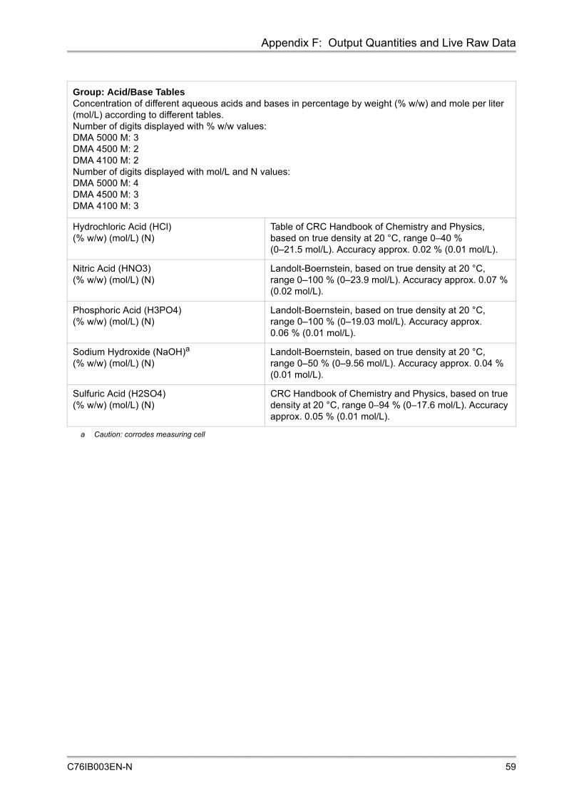
Appendix F: Output Quantities and Live Raw Data
Group: Acid/Base TablesConcentration of different aqueous acids and bases in percentage by weight (% w/w) and mole per liter (mol/L) according to different tables.Number of digits displayed with % w/w values:DMA 5000 M: 3DMA 4500 M: 2DMA 4100 M: 2Number of digits displayed with mol/L and N values:DMA 5000 M: 4DMA 4500 M: 3DMA 4100 M: 3
Hydrochloric Acid (HCl) (% w/w) (mol/L) (N)
Table of CRC Handbook of Chemistry and Physics, based on true density at 20 °C, range 0–40 % (0–21.5 mol/L). Accuracy approx. 0.02 % (0.01 mol/L).
Nitric Acid (HNO3) (% w/w) (mol/L) (N)
Landolt-Boernstein, based on true density at 20 °C, range 0–100 % (0–23.9 mol/L). Accuracy approx. 0.07 % (0.02 mol/L).
Phosphoric Acid (H3PO4) (% w/w) (mol/L) (N)
Landolt-Boernstein, based on true density at 20 °C, range 0–100 % (0–19.03 mol/L). Accuracy approx. 0.06 % (0.01 mol/L).
Sodium Hydroxide (NaOH)a
(% w/w) (mol/L) (N)
a Caution: corrodes measuring cell
Landolt-Boernstein, based on true density at 20 °C, range 0–50 % (0–9.56 mol/L). Accuracy approx. 0.04 % (0.01 mol/L).
Sulfuric Acid (H2SO4) (% w/w) (mol/L) (N)
CRC Handbook of Chemistry and Physics, based on true density at 20 °C, range 0–94 % (0–17.6 mol/L). Accuracy approx. 0.05 % (0.01 mol/L).
C76IB003EN-N 59

Appendix F: Output Quantities and Live Raw Data
Group: API Functions
The API functions automatically convert the density values of petroleum samples measured at any temperature to density, API gravity or specific gravity at 15 °C or 60 °F, according to ASTM D1250-08 and DIN 51757. Additionally, the same API functions are available for a reference temperature of 20 °C according to the "IP Petroleum Measurement Paper No. 3, 1988".The samples are divided into the groups crude oil (group A), fuel to heating oil (group B) and lubricants (group D).Number of digits displayed with API density values:DMA 5000 M: 5DMA 4500 M: 4DMA 4100 M: 4Number of digits displayed with °API Gravity values:DMA 5000 M: 3DMA 4500 M: 2DMA 4100 M: 2
°API Gravity 15 °C API gravity converted to 15 °C.
°API Gravity 20 °C API gravity converted to 20 °C.
°API Gravity 29.5 °C API gravity converted to 29.5 °C.
°API Gravity 60 °F API gravity converted to 60 °F.
API Density 15 °C Conversion of density at measuring temperature to density at 15 °C.
API Density 20 °C Conversion of density at measuring temperature to density at 20 °C.
API Density 29.5 °C Conversion of density at measuring temperature to density at 29.5 °C.
API Density 60 °F Conversion of density at measuring temperature to density at 60 °F.
API Input Quantity Selection of the input parameter for API calculations: Density, Density (not visc.-corr.) or a Special Adjustment.
API Product Group Selection of the API product group for calculation of API gravity, density and specific gravity.
API Specific Gravity 15 °C Conversion of density at measuring temperature to specific gravity at 15 °C.
API Specific Gravity 20 °C Conversion of density at measuring temperature to specific gravity at 20 °C.
API Specific Gravity 29.5 °C Conversion of density at measuring temperature to specific gravity at 29.5 °C.
API Specific Gravity 60 °F Conversion of density at measuring temperature to specific gravity at 60 °F.
Group: Special AdjustmentsUp to 5 special adjustments can be stored in the DMA M, see section 8.3.5.
60 C76IB003EN-N

Appendix F: Output Quantities and Live Raw Data
F.2: Live Raw Data
For viewing and printing live raw data as well as for a list of software specific live raw data refer to the General Software Functions Manual, section 10.8.
DMA Density
Quantities not mentioned in the following table are described in the tables above (e.g. Density, Density Temperature, Density (not visc.-corr.), etc.).
DCB - Air Pressure
dD Harmonic Value Damping of the first harmonic.
Delta RHO Value Difference between density calculated from 1st harmonic and density calculated from fundamental oscillation.
Density 1st Harmonic Density calculated from the 1st harmonic of the U-tube.
Density Progress Indicator (0–100) for the progress of the measurement.
e Viscosity correction factor.
Fill Status Status information about correct filling of the U-tube. Values different from zero indicate an incorrect filling.
RHO NC Harmonic Value Not viscosity-corrected density calculated form the 1st harmonic.
RHO17 Value Viscosity-corrected density, valid if the viscosity is less than 700 mPa·s.
RHOg5 Value Viscosity corrected density, valid if the viscosity is greater than 500 mPa·s.
Status Value Status information indicating the temperature status of the cell.
Air Pressure Currently measured air pressure.
Air Pressure Condition Current status of the measurement.
Air Pressure State Status of the air pressure measurement.
Air Pressure Substate Detailed information about the status of the air pressure measurement.
C76IB003EN-N 61

Appendix G: List of Quick Settings Parameters
Appendix G: List of Quick Settings ParametersDepending on the sample list mode, different quick setting parameters are set by default:
• If the "No Sample List" mode is used: Sample name, measurement mode and "Density Temperature" (not for users of the user group "Operator")
• If the "Sample List" mode is used: Measurement mode and "Density Temperature" (not for users of the user group "Operator")
Parameter Type Parameter Select Description
Sample Name only in the "No Sample List" mode
Measurement Mode S (Standard) Perform a standard measurement.
C (Check) Perform one of the predefined checks. It is only possible to select a check which has been defined for the selected method before.
MM (Multiple Measurement) Perform 2–10 measurements of a single sample automatically.
RM (Repeated Mode) Perform repeated measurements of a single sample by filling the sample up to 5 times. You define a maximum deviation of two subsequent measurements.
MF (Multiple Filling) Perform multiple measurements of a single sample after filling the sample 2–5 times.
TS (Temperature Scan) Perform a temperature scan.
TTS (Temperature Table Scan) Perform a temperature table scan.
Density Temperature Set the temperature of the density measuring cell between –25 and 95 °C (or 90 °C).
Density Measurement finished by
Predetermination default
Equilibrium (for DMA 4100 M / DMA 4500 M)
Equilibrium fast (for DMA 5000 M)
Equilibrium medium
Equilibrium slow
None (use method default)
Density Timeout Set the timeout for density measurement (30–3600 s, default 600 s).
Density FillingCheck™ Always active default
Not active
Active during measurement
None (use method default)
62 C76IB003EN-N

Appendix G: List of Quick Settings Parameters
Density API Product Group
A - Crude oil default
B - Fuels
D - Lubes
None (use method default)
Density API Input Quantity
Density default
Density (not visc. - corr.)
Special Adjustment up to 5
None (use method default)
Density Canadian Excise Alcohol Table
Special Adjustment 1, …, 5 default
None (use method default)
User-defined data fields if set as mandatory in the sample list settings
User functions of the "Constant" type
if activated in the method settings
Parameter Type Parameter Select Description
C76IB003EN-N 63

Appendix H: Density Tables
Appendix H: Density Tables
Density of Air1
For the temperature t [in °C] and the pressure p [in mbar or hPa] the density ρ of air [in g/cm3] can be calculated by the following formula (given an air humidity of 50 %):
The numbers are valid for a CO2 content in air of 0.03 % by volume; the numbers change by ±1/19000 for every change in CO2 volume content of ±0.0001.
Composition of dry air [in v/v]:78.110 % N2 / 20.938 % O2 / 0.916 % Ar / 0.033 % CO2 / 0.002 % Ne
NOTICEThe factory default reference values for the density of air and water are based on the formula of Spieweck and Bettin and cover the whole measuring range of the instrument.
1 Literature: F. Spieweck, H. Bettin: Review: Solid and liquid density determination. tm – Technisches Messen 59 (1992) 7–8, pp. 285–292.
Meas. temp. [in °C]
Density [in g/cm3] at the pressure [in mbar (=hPa)]
900 920 940 960 980 1000 1013.25 1050
–10 0.001200 0.001227 0.001253 0.001280 0.001306 0.001333 0.001350 0.001399
–5 0.001176 0.001202 0.001228 0.001254 0.001280 0.001306 0.001323 0.001371
0 0.001152 0.001177 0.001203 0.001228 0.001254 0.001279 0.001296 0.001343
5 0.001129 0.001154 0.001179 0.001204 0.001229 0.001254 0.001271 0.001317
10 0.001107 0.001131 0.001156 0.001181 0.001205 0.001230 0.001246 0.001291
15 0.001085 0.001110 0.001134 0.001158 0.001182 0.001206 0.001222 0.001267
20 0.001065 0.001088 0.001112 0.001136 0.001160 0.001184 0.001199 0.001243
25 0.001045 0.001068 0.001091 0.001115 0.001138 0.001162 0.001177 0.001220
30 0.001025 0.001048 0.001071 0.001094 0.001117 0.001140 0.001156 0.001198
35 0.001007 0.001029 0.001052 0.001075 0.001097 0.001120 0.001135 0.001176
40 0.000989 0.001011 0.001033 0.001055 0.001078 0.001100 0.001115 0.001156
45 0.000971 0.000993 0.001015 0.001037 0.001059 0.001081 0.001095 0.001135
50 0.000954 0.000976 0.000997 0.001019 0.001040 0.001062 0.001076 0.001116
55 0.000938 0.000959 0.000980 0.001001 0.001023 0.001044 0.001058 0.001097
60 0.000922 0.000943 0.000964 0.000984 0.001005 0.001026 0.001040 0.001079
65 0.000906 0.000927 0.000947 0.000968 0.000989 0.001009 0.001023 0.001061
70 0.000891 0.000911 0.000932 0.000952 0.000972 0.000993 0.001006 0.001043
75 0.000877 0.000897 0.000917 0.000937 0.000957 0.000977 0.000990 0.001027
80 0.000862 0.000882 0.000902 0.000922 0.000941 0.000961 0.000974 0.001010
85 0.000849 0.000868 0.000887 0.000907 0.000926 0.000946 0.000959 0.000995
90 0.000835 0.000854 0.000874 0.000893 0.000912 0.000931 0.000944 0.000979
0.34844 p 0.5 0.252 t 2.0582– –273.15 t+
------------------------------------------------------------------------------------------------------- 1000=
64 C76IB003EN-N

Appendix H: Density Tables
Density of Water (0 °C to 95 °C)
Formula for the calculation of the density of water
• according to Spieweck/Bettin:
• according to CIPM:
a0 = 9.998 395 2 ·102 kg/m3
a1 = 1.695 257 7 ·101 °C–1 kg/m3
a2 = –7.990 512 7 ·10–3 °C–2 kg/m3
a3 = –4.624 175 7 ·10–5 °C–3 kg/m3
a4 = 1.058 460 1 ·10–7 °C–4 kg/m3
a5 = –2.810 300 6 ·10–10°C–5 kg/m3
b = 1.688 723 6 ·10–2 °C–1
a1 = –3.983 035 °Ca2 = 301.797 °Ca3 = 522 528.9 °C2
a4 = 69.348 81 °Ca5 = 999.974 950 kg/m3
t an t
nn 0=
5
1 b t+
--------------------------------=
t a5 1t a1+ 2 t a2+
a3 t a4+ ---------------------------------------------–=
C76IB003EN-N 65

Appendix H: Density Tables
T °C
Density of water
T °C
Density of water
T °C
Density of water
CIPM/ IAPWS 95
Spieweck/ Bettin
CIPM/ IAPWS 95
Spieweck/ Bettin
CIPM/ IAPWS 95
Spieweck/ Bettin
0 0.999843 0.999840 40 0.992215 0.992212 80 0.971790 0.971785
1 0.999902 0.999899 41 0.991830 0.991826 81 0.971165 0.971159
2 0.999943 0.999940 42 0.991437 0.991432 82 0.970534 0.970528
3 0.999967 0.999964 43 0.991036 0.991031 83 0.969898 0.969892
4 0.999975 0.999972 44 0.990628 0.990623 84 0.969257 0.969252
5 0.999967 0.999964 45 0.990213 0.990208 85 0.968611 0.968606
6 0.999943 0.999940 46 0.989791 0.989786 86 0.967961 0.967955
7 0.999904 0.999901 47 0.989362 0.989358 87 0.967305 0.967300
8 0.999851 0.999848 48 0.988926 0.988922 88 0.966645 0.966639
9 0.999784 0.999781 49 0.988484 0.988479 89 0.965980 0.965974
10 0.999703 0.999699 50 0.988035 0.988030 90 0.965310 0.965304
11 0.999608 0.999605 51 0.987579 0.987575 91 0.964635 0.964630
12 0.999500 0.999497 52 0.987117 0.987113 92 0.963955 0.963950
13 0.999380 0.999377 53 0.986649 0.986644 93 0.963271 0.963266
14 0.999247 0.999244 54 0.986174 0.986169 94 0.962582 0.962577
15 0.999103 0.999099 55 0.985693 0.985688 95 0.961888 0.961883
16 0.998946 0.998942 56 0.985206 0.985201
17 0.998778 0.998774 57 0.984712 0.984707
18 0.998598 0.998595 58 0.984213 0.984208
19 0.998408 0.998404 59 0.983707 0.983702
20 0.998207 0.998203 60 0.983196 0.983191
21 0.997995 0.997991 61 0.982678 0.982673
22 0.997773 0.997769 62 0.982155 0.982150
23 0.997541 0.997537 63 0.981626 0.981621
24 0.997299 0.997295 64 0.981091 0.981086
25 0.997047 0.997043 65 0.980551 0.980546
26 0.996786 0.996782 66 0.980005 0.979999
27 0.996515 0.996511 67 0.979453 0.979448
28 0.996235 0.996232 68 0.978896 0.978890
29 0.995946 0.995943 69 0.978333 0.978327
30 0.995649 0.995645 70 0.977765 0.977759
31 0.995342 0.995339 71 0.977191 0.977185
32 0.995027 0.995024 72 0.976612 0.976606
33 0.994704 0.994700 73 0.976028 0.976022
34 0.994372 0.994369 74 0.975438 0.975432
35 0.994033 0.994029 75 0.974843 0.974837
36 0.993685 0.993681 76 0.974243 0.974237
37 0.993329 0.993325 77 0.973637 0.973632
38 0.992965 0.992962 78 0.973027 0.973021
39 0.992594 0.992591 79 0.972411 0.972405
66 C76IB003EN-N

Appendix I: Instrument Software Versions
Appendix I: Instrument Software Versions
Instrument software version
Date of release
Document number
Comments
V1.00 18.06.2008 C76IB01A First version released
V1.10 14.08.2008 C76IB01B Users with administrator rights can update the operating system and adjust the camera position.
V1.52 27.02.2009 C76IB01C • Limits can be defined for any output quantity• 10 sample lists available• Statistics (minimum, maximum, standard deviation,
mean)• 5 special adjustments available• LIMS support• Custom checks can be defined• Check history for the last 100 checks• 50 methods can be defined• Graphs can be displayed/printed: KB graph,
calculator• Selective backup/restore implemented• Temperature scan (DMA 5000 M only)
V1.60 19.08.2009 C76IB01DC76IB01E
• The sequence of items in the data browser, favorites list and result output can be changed
• Screen saver implemented• Feedback beep after measurement can be selected• Single results can be deleted• Audit Trail: automatic logoff after 60 minutes without
user interaction• RS-232 connection with external PC possible• Changes of method settings limited to users with
administrator rights• Extended support of external keyboard
V1.70 15.01.2010 C76IB01F • Group calculator• GUI performance improved• Audit trail: password rules• Temperature scan for all instruments• Mandatory data fields• Installing of language pack• Three new RS-232 commands according to DMA
classic instruments• More detailed information in system information• Live raw data can be printed• Screen saver is disabled by interface commands
C76IB003EN-N 67

Appendix I: Instrument Software Versions
V2.00 10.09.2010 C76IB003EN-A • GUI performance improved• Data browser filter: only users and methods used are
available• More detailed information about firmware module
state during startup (new initialization screen instead of online screen)
• Safe mode operation after firmware errors• Sample list: ring buffer for 200 sample list entries.
Sample list entries older than 24 hours are automatically removed
• Data memory can be set as ring buffer if Audit Trail is deactivated
• <Monitor> button to unfreeze the screen moved to the quick access area
• Allowed minimum step size in temperature scans depends now on the equilibrium setting of the density module
• Keyboard and bar code settings: the sample list can be edited with a bar code reader (tab key as terminator)
• <Redo> option after adjustments available• New air pump setting: Automatic stop when the
density value is stable• Audit Trail stores more detailed and structured
information on changes to the system• New RS-232 commands: "set temperature" and "help"• Printing a single sample on a list report is not
supported any more• Current API product group for API calculation is now
displayed in the calculator
V2.10 22.12.2010 C76IB003EN-B New multiple measurements menu
Instrument software version
Date of release
Document number
Comments
68 C76IB003EN-N

Appendix I: Instrument Software Versions
V2.20 12.09.2011 C76IB003EN-C • New system security settings implemented: different security levels, electronic signature, auto logoff and password expiry
• "Audit Trail" menu now in the "System Security" menu• Quick settings implemented for convenient change of
measurement settings• "No Sample List" mode available• Methods can be hidden and arranged• New "Constant" user function added• Printing support for adjustments added• Camera images during adjustment/check procedure
added• PDF print reports and Excel exports optimized• For instruments from DCB version 1.000.009:
Temperature range extended up to 95 °C• Support of CAN bar code readers• Hardware redesign: SD card is not used anymore• Show current method as postfix• Standardized output for the RS-232 report• Pre-filled output fields after switching to another
layout• Updating UI software, OS image and firmware
modules at once without user confirmation upon every step (if all firmware modules are attached during the update)
• Include adjustment data in backup/restore• Service Reminder• Possibility to activate filling warning only during
measurement• Configuration of log files
C76IB003EN-D Remark added to the instruction manual
V2.21 13.01.2012 C76IB003EN-E • Supports combination with Abbemat Performance and Abbemat Performance Plus refractometers
• Supports combination with Lovis ME rolling-ball viscometer
Instrument software version
Date of release
Document number
Comments
C76IB003EN-N 69

Appendix I: Instrument Software Versions
V2.30 24.05.2012 C76IB003EN-FC76IB003EN-G
• Redesign of graphical user interface• New filter criteria: time, measurement mode• Notification emails• New measurement modes: Multiple Filling,
Temperature Table Scan, Repeated Mode• Additional trigonometric functions for the calculator:
sin, cos, tan, ln, log, sqrt, asin, acos, atan• Maximum number of user functions increased to 80• Maximum number of methods increased to 200• Printing and exporting of adjustment data, check data,
user functions, calculator results and statistics improved
• Automatic generation of an IQ/OQ document• Selecting checks to be shown on GxP compliant
reports possible• KB graph export also includes KB values
V2.40 06.12.2013 C76IB003EN-H • Zoom function for KB graph and calculator data diagram graph available
• Auto air check added• Possibility to redo adjustment steps during the "High
Density / High Viscosity Adjustment" procedure• Advanced security settings added• Temperature Extrapolation Settings implemented• API Product group for special applications added• Possibility to deactivate ring buffer for check data• Adjustment analysis added
V2.41 04.04.2014 C76IB003EN-I • Additional air and water tables based on the CIPM and IAPWS formula to be used as reference values
• Possibility to set a line break in the result output
V2.42 24.06.2014 C76IB003EN-JC76IB003EN-K
No changes for DMA 4100/4500/5000 MV2.60 07.04.2015 C76IB003EN-L
V2.70 27.07.2015 C76IB003EN-MC76IB003EN-N
Instrument software version
Date of release
Document number
Comments
70 C76IB003EN-N

Appendix J: Calibration Approval
Appendix J: Calibration ApprovalThe software of the instrument consists of several parts (system software, graphical user interface, result determination, data storage, etc.). Essential for the measurement and calculation of the density is the firmware of the DSP-SAC module. This module measures and calculates the density values.
Module Firmware version
DSP-SAC 9.004.017
C76IB003EN-N 71

Appendix K: Declaration of Conformity
Appendix K: Declaration of Conformity
72 C76IB003EN-N

Appendix L: Menu Tree
Appendix L: Menu TreeThe menu tree shows which parts of the menu are accessible for users with administrator, manager or operator rights using the following colors:
Administrator
Administrator, Manager
Administrator, Manager, Operator
Checks/Adjustments Checks
Air/Water Adjustment
Other Adjustments Density Module Air/Water Adjustment
Temperature Range Adjustment
High Density/Viscosity Adjustmenta
Special Adjustments
Reset To Factory Adjustment
DCB Module Atmospheric Pressure Sensor Adjustment
Data Memory Measured Data
Statistic
Delete Measured Data
Audit Trail
Check Data
Delete Check Data
Adjustment Data Density Module Density Adjustment
Temperature Adjustment
Density Adjustment KB Graph
Special Adjustment
Print or Export Adjustment Data
Delete Audit Trail
Methods Method Settings Density (Current Method) Activate Modules / Constantsb
Measurement Mode (S)
Repeated Mode Settings
Density Module
Display Layout
Result Output
Limits
Formula Parameters
Quick Settings Management
Density (not visc.-corr.)
°Brix
Ethanol (% w/w OIML-ITS90)
Ethanol (% v/v OIML-ITS90)
Ethanol (°Proof 60 °F AOAC)
Crude Oil (API)
Fuel Oil (API)
Lubricants (API)
Sulfuric Acid (% w/w)
Method Management
Method Visibility
C76IB003EN-N 73

Appendix L: Menu Tree
Setup Measuring System Settings Density Module
Sample List Sample List / Sample Settings
User-defined Data Fields
Sample List Warnings
Mandatory Data Fields
Camera
Air Pump
Temperature Extrapolation Settings
Control Panel Date and Time
Regional Settings
Input Units
Printer Management
Network
Instrument Name and Location
Screen Saver
Sound Settings
Calibrate Touch Screen
Calibrate External Touch Screen
Keyboard and Bar Code Settings
FTP Settings
Advanced Camera Settingsc
SMTP Server Settings
Display Brightness
System Security Security Level
Audit Trail
Electronic Signature
Logon Settings
Increased Security
Advanced Security
User Managementc
Printout Settings Automatic Printout
Report Management
Select Logos
Import Logos
Name and Address
Data Browser Settings
Expert Settings User Function Management
Delete User Function
Calculator
Group Calculator
Check Management
Data Memory Settings
74 C76IB003EN-N

Appendix L: Menu Tree
Service Backup Instrument Settings
Restore Instrument Settings
Update System Update
Module Firmware Update
Install Language Pack
Logging Configuration
System Information
IQ/OQ Report
Export Instrument Data
Full System Backup
Full System Restore
Live Raw Data DMA Density
Calculations
DCB - Air Pump
DCB - Air Pressure
DCB - Environment
DCB - CAN Connector
a DMA 5000 M onlyb Only if a "Constant" user function was created and/or if a module is connectedc Users of any user group may change their own password
C76IB003EN-N 75

Index
Index
Symbols
°Balling 58°Brix 58°Plato 58<Menu> button 17<Method> button 17<Quick Settings> button 17<Sample List> button 17<Start> button 17<Stop> button 17
A
accuracy 24acid/base tables 59adjustment
aborting 26, 27adjustment data 30adjustment media 26adjustment result 27air adjustment 27air/water adjustment 26atmospheric pressure sensor adjustment 28definition 23error 48factory adjustment 20for high pressure measurements 50high density/high viscosity adjustment 27regular 11resetting to factory adjustment 30special adjustment 11, 28, 29temperature range adjustment 27trouble shooting 52validity of factory adjustment 22water adjustment 27
air bubbles 27, 28air check 24air humidity 44, 48air pressure 27air pump
outlet 15starting 18, 41
alcohol concentration 32AOAC 57API density 32, 60API functions
API parameters 36API product group 36output quantities 60
API gravity 60API specific gravity 60apparent density 56
apparent specific gravity 56atmospheric pressure sensor 28auto air check 25
B
Baumé 58bubble detection 38, 40
C
calibration 31calibration certificate 31calibration liquid 31calibration protocol 31certified standard liquid 31definition 23
cameraadjusting the camera position 51bubble detection 40picture 51
Canadian excise alcohol table 28, 29, 36, 57check history 25check settings 23
time interval 23tolerance 23
checkingdefinition 23
cleaningcleaning and drying procedure with Xsample fill-ing equipment 42cleaning and drying procedure without Xsamplefilling equipment 41cleaning liquids 41frequency 41instrument housing 42touch screen 42
cleaning routine 41concentration measurement 10
accuracy 10, 43condensation 48cooling kit 49crude oil 32
D
d 57d (not visc.-corr.) 57damping 11, 57, 61date and time 22, 24degassing 46density 56
density values 56
76 C76IB003EN-N

Index
formula 10of water 65
density (not visc.-corr.) 56density check
check results 25check/SOP data 25performing 24performing a density check 24
density condition 56density tables 64density temperature 56display
buttons 17, 19clock 17content area 17output field 17progress bar 17quick access buttons 18sample number 17user indicator 17
dry air 64dry air supply 48drying 41drying cartridge 48
E
equilibrium 33, 43error status 18, 40ethanol 32, 41, 42, 43ethanol concentration 57ethanol tables 57external measuring module 44extract 58extract/sugar 43extract/sugar tables 58
F
fillingautomatically 39bubbling samples 46gases 47highly viscous samples 46liquids in aerosol cans 47pastes 46suspensions and emulsions 46with a funnel 38with a peristaltic pump 39with a syringe 38
FillingCheck™activating, deactivating 33coefficients 27, 28definition 11
fuel oil 33
G
gas bubbles 11, 46, 49
H
H2SO4 33, 43, 59H3PO4 43, 59HCl 43, 59high humidity/low temperature conditions 48HM C&E 58HNO3 43, 59hydrochloric acid 59
I
injection adapter tool 20, 21installation
first check 22injection adapters 20silicone hose 21switching instrument on/off 22waste vessel 21
instrument status 18interface
CAN 16Ethernet 16RS-232 16S-BUS 16USB 15, 16VGA 16
IUPAC 58
K
Kaempf 58KB graph 30
L
leak tightness 21live camera view 18, 38lubricants 33
M
main menu 17measurement modes 34measurement status 56measurements
performing 39progress of 39speeding up 39trouble shooting 52
measurements using special adjustments 28measuring at high pressure 50measuring at high temperatures 49
C76IB003EN-N 77

Index
measuring at low temperatures 49measuring cell 11, 18, 51, 52, 56measuring errors 40measuring methods
definition 32factory preset methods 32maximum number 33
measuring mode 17measuring range 43measuring settings
density module 33measuring temperature 24, 48menu
accessing 19current position in 19options 19
method°Brix 32Crude Oil (API) 32Density 32Density (not visc.-corr.) 32Ethanol (% v/v OIML-ITS-90) 32Ethanol (% w/w OIML-ITS-90) 32Ethanol (°Proof 60 °F AOAC) 32Fuel Oil (API) 33Lubricants (API) 33Sulfuric Acid (% w/w, mol/l) 33
monitor mode 17
N
NaOH 43, 59navigation path 19nitric acid 59
O
OIML 58output quantity 29, 36, 57
P
period of oscillation 57peristaltic pump 39phosphoric acid 59predetermination 33printout
trouble shooting 54Proof 58
R
reference oscillator 11, 57reference temperature 60
repeatability 43reproducibility 46residues 38, 41
S
sample amount 38sample changer 14sample name 37sample status 40serial number 16, 55set temperature 33, 39, 58SG 10, 58silica gel 48sodium hydroxide 59soft drinks 32special adjustment 11, 29, 36, 60specific gravity 56specific gravity (not visc.-corr.) 56specific gravity formula 10specific gravity t/04 56storing the instrument 42sucrose 58sugar 32sulfuric acid 33, 59suspensions 46
T
temperature 24, 56, 64temperature range 11, 22, 26temperature scan 34, 36temperature table scan 36ThermoBalance™ 11touch screen 11, 15, 44true density 57, 58, 59type plate 16
U
U-tube 11, 57U-tube method 10U-View™ 11, 18
V
viscosity 31, 46, 57viscosity correction 43, 56voltage 44
W
water check 24wetted parts 45
78 C76IB003EN-N