c75-ra-1 part a - rudder skeleton - zenith aircraft company · 2019-06-07 · rudder parts zenith...
TRANSCRIPT
Cruzer CH 750
Zenith Aircraft Company www.zenithair.com
PART A: RUDDER SKELETON Section C75-RA-1, Page 1 of 12
Revision 2.0 (03/23/17) © 2013 Zenith Aircraft Co
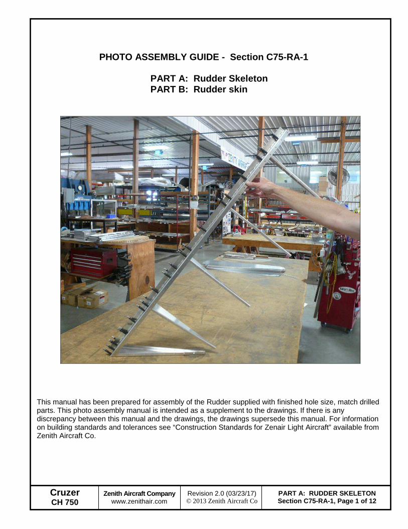
PHOTO ASSEMBLY GUIDE - Section C75-RA-1
PART A: Rudder Skeleton PART B: Rudder skin
This manual has been prepared for assembly of the Rudder supplied with finished hole size, match drilled parts. This photo assembly manual is intended as a supplement to the drawings. If there is any discrepancy between this manual and the drawings, the drawings supersede this manual. For information on building standards and tolerances see “Construction Standards for Zenair Light Aircraft” available from Zenith Aircraft Co.
Cruzer CH 750
Zenith Aircraft Company www.zenithair.com
PART A: RUDDER SKELETON Section C75-RA-1, Page 2 of 12
Revision 2.0 (03/23/17) © 2013 Zenith Aircraft Co
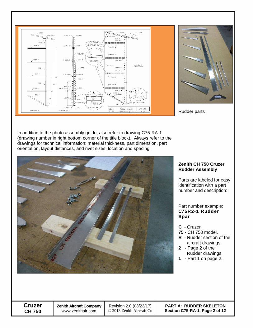
In addition to the photo assembly guide, also refer to drawing C75-RA-1 (drawing number in right bottom corner of the title block). Always refer to the drawings for technical information: material thickness, part dimension, part orientation, layout distances, and rivet sizes, location and spacing.
Rudder parts
Zenith CH 750 Cruzer Rudder Assembly Parts are labeled for easy identification with a part number and description: Part number example: C75R2-1 Rudder Spar C - Cruzer 75 - CH 750 model. R - Rudder section of the
aircraft drawings. 2 - Page 2 of the
Rudder drawings. 1 - Part 1 on page 2.
Cruzer CH 750
Zenith Aircraft Company www.zenithair.com
PART A: RUDDER SKELETON Section C75-RA-1, Page 3 of 12
Revision 2.0 (03/23/17) © 2013 Zenith Aircraft Co
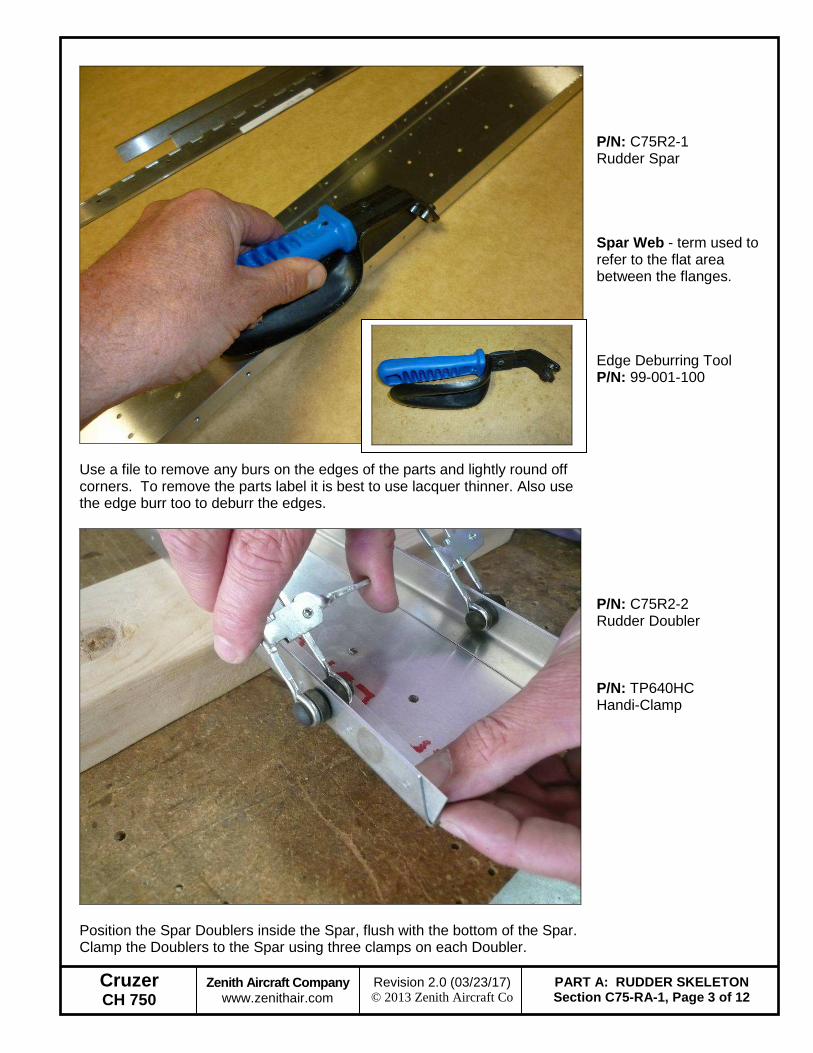
Use a file to remove any burs on the edges of the parts and lightly round off corners. To remove the parts label it is best to use lacquer thinner. Also use the edge burr too to deburr the edges.
P/N: C75R2-1 Rudder Spar Spar Web - term used to refer to the flat area between the flanges. Edge Deburring Tool P/N: 99-001-100
Position the Spar Doublers inside the Spar, flush with the bottom of the Spar. Clamp the Doublers to the Spar using three clamps on each Doubler.
P/N: C75R2-2 Rudder Doubler P/N: TP640HC Handi-Clamp
Cruzer CH 750
Zenith Aircraft Company www.zenithair.com
PART A: RUDDER SKELETON Section C75-RA-1, Page 4 of 12
Revision 2.0 (03/23/17) © 2013 Zenith Aircraft Co
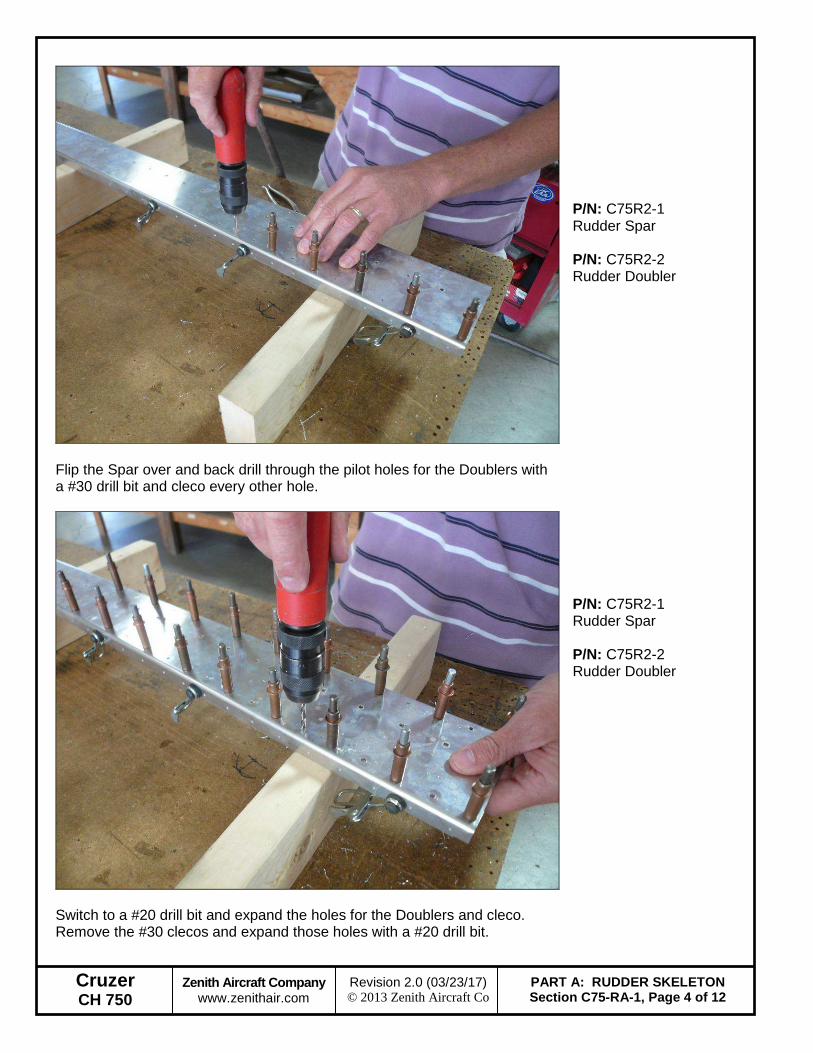
Flip the Spar over and back drill through the pilot holes for the Doublers with a #30 drill bit and cleco every other hole.
P/N: C75R2-1 Rudder Spar P/N: C75R2-2 Rudder Doubler
Switch to a #20 drill bit and expand the holes for the Doublers and cleco. Remove the #30 clecos and expand those holes with a #20 drill bit.
P/N: C75R2-1 Rudder Spar P/N: C75R2-2 Rudder Doubler
Cruzer CH 750
Zenith Aircraft Company www.zenithair.com
PART A: RUDDER SKELETON Section C75-RA-1, Page 5 of 12
Revision 2.0 (03/23/17) © 2013 Zenith Aircraft Co
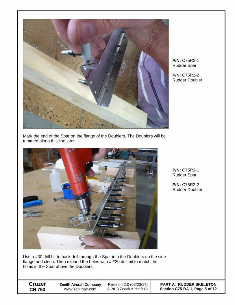
Mark the end of the Spar on the flange of the Doublers. The Doublers will be trimmed along this line later.
P/N: C75R2-1 Rudder Spar P/N: C75R2-2 Rudder Doubler
Use a #30 drill bit to back drill through the Spar into the Doublers on the side flange and cleco. Then expand the holes with a #20 drill bit to match the holes in the Spar above the Doublers.
P/N: C75R2-1 Rudder Spar P/N: C75R2-2 Rudder Doubler

Cruzer CH 750
Zenith Aircraft Company www.zenithair.com
PART A: RUDDER SKELETON Section C75-RA-1, Page 6 of 12
Revision 2.0 (03/23/17) © 2013 Zenith Aircraft Co
Remove the Doublers from the Spar. Use a pair of Snips to trim the Doublers along the line. Be careful to not fully close the snips when making a cut, doing so will kink the material. Use a file to smooth the cut edge.
P/N: C75R2-2 Rudder Doubler
Use a large drill bit to deburr the holes in all the Rudder parts, including the ribs. A couple quick turns with light pressure will remove the burrs. Be careful not to countersink the holes!
P/N: C75R2-2 Rudder Doubler
Cruzer CH 750
Zenith Aircraft Company www.zenithair.com
PART A: RUDDER SKELETON Section C75-RA-1, Page 7 of 12
Revision 2.0 (03/23/17) © 2013 Zenith Aircraft Co
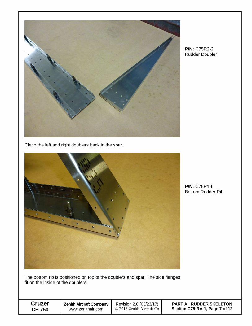
Cleco the left and right doublers back in the spar.
P/N: C75R2-2 Rudder Doubler
The bottom rib is positioned on top of the doublers and spar. The side flanges fit on the inside of the doublers.
P/N: C75R1-6 Bottom Rudder Rib
Cruzer CH 750
Zenith Aircraft Company www.zenithair.com
PART A: RUDDER SKELETON Section C75-RA-1, Page 8 of 12
Revision 2.0 (03/23/17) © 2013 Zenith Aircraft Co
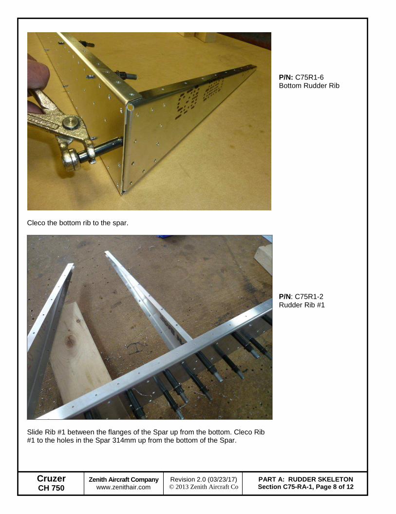
Cleco the bottom rib to the spar.
P/N: C75R1-6 Bottom Rudder Rib
Slide Rib #1 between the flanges of the Spar up from the bottom. Cleco Rib #1 to the holes in the Spar 314mm up from the bottom of the Spar.
P/N: C75R1-2 Rudder Rib #1
Cruzer CH 750
Zenith Aircraft Company www.zenithair.com
PART A: RUDDER SKELETON Section C75-RA-1, Page 9 of 12
Revision 2.0 (03/23/17) © 2013 Zenith Aircraft Co
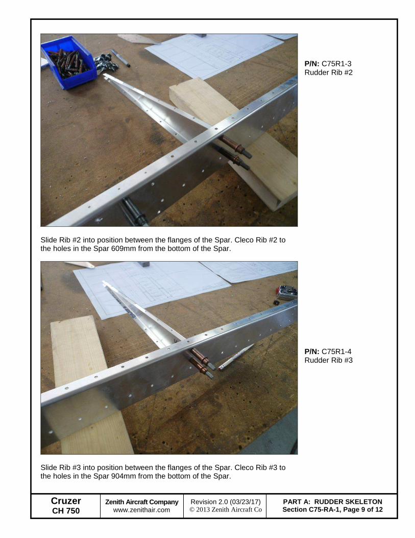
Slide Rib #2 into position between the flanges of the Spar. Cleco Rib #2 to the holes in the Spar 609mm from the bottom of the Spar.
P/N: C75R1-3 Rudder Rib #2
Slide Rib #3 into position between the flanges of the Spar. Cleco Rib #3 to the holes in the Spar 904mm from the bottom of the Spar.
P/N: C75R1-4 Rudder Rib #3
Cruzer CH 750
Zenith Aircraft Company www.zenithair.com
PART A: RUDDER SKELETON Section C75-RA-1, Page 10 of 12
Revision 2.0 (03/23/17) © 2013 Zenith Aircraft Co
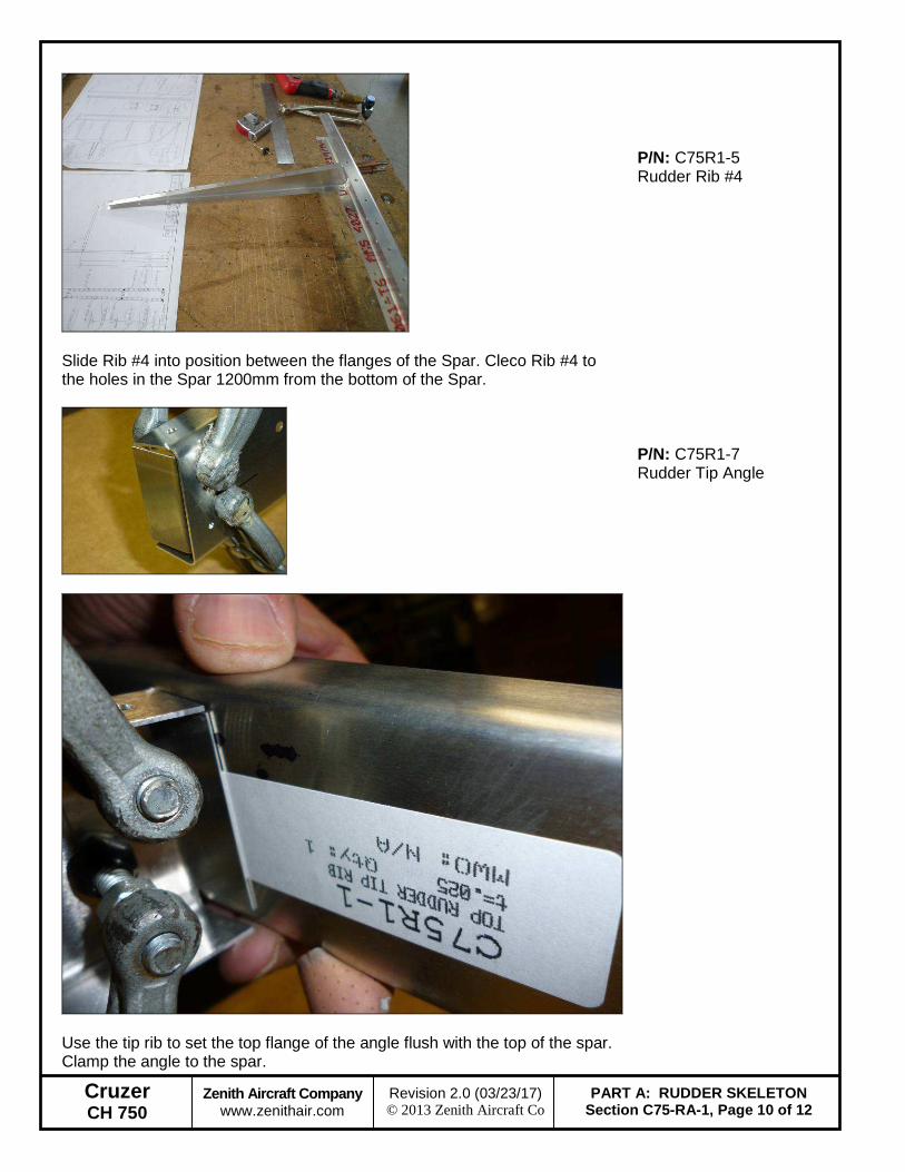
Slide Rib #4 into position between the flanges of the Spar. Cleco Rib #4 to the holes in the Spar 1200mm from the bottom of the Spar.
P/N: C75R1-5 Rudder Rib #4
P/N: C75R1-7 Rudder Tip Angle
Use the tip rib to set the top flange of the angle flush with the top of the spar. Clamp the angle to the spar.
Cruzer CH 750
Zenith Aircraft Company www.zenithair.com
PART A: RUDDER SKELETON Section C75-RA-1, Page 11 of 12
Revision 2.0 (03/23/17) © 2013 Zenith Aircraft Co
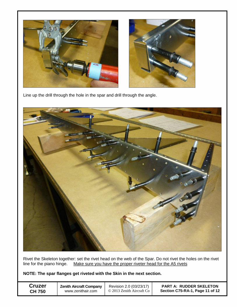
Line up the drill through the hole in the spar and drill through the angle.
Rivet the Skeleton together: set the rivet head on the web of the Spar. Do not rivet the holes on the rivet line for the piano hinge. Make sure you have the proper riveter head for the A5 rivets NOTE: The spar flanges get riveted with the Skin in the next section.
Cruzer CH 750
Zenith Aircraft Company www.zenithair.com
PART A: RUDDER SKELETON Section C75-RA-1, Page 12 of 12
Revision 2.0 (03/23/17) © 2013 Zenith Aircraft Co
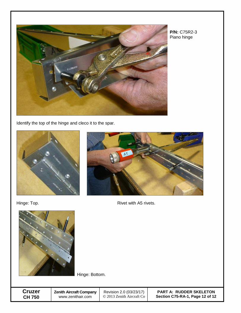
Identify the top of the hinge and cleco it to the spar.
P/N: C75R2-3 Piano hinge
Hinge: Top. Rivet with A5 rivets.
Hinge: Bottom.