c5 corvette e-force supercharger installation kit pn - lingenfelter
TRANSCRIPT
Lingenfelter Performance Engineering1557 Winchester Road
Decatur, IN 46733(260) 724-2552
(260) 724-8761 faxwww.lingenfelter.com
Revision - 2.9 Release date May 22, 2012
C5 Corvette E-Force SuperchargerInstallation Kit
PN: L250280197 (Installation kit only)PN:L250290197 (Complete Kit)

Page 1
IntroductionThank you for purchasing the Lingenfelter Performance Engineering E-Force Supercharger installation kit for the C5 Corvette. This kit includes the parts necessary to allow for the Edelbrock GM LS2 Supercharger System, which is designed for the C6 Corvette, to be installed onto the C5 Corvette. The Lingenfelter C5 E-Force Supercharger installation kit can be purchased as an entire kit, or as individual parts through any Lingenfelter authorized dealer. It is important to note that the contents of the Lingenfelter installation instructions are not meant to replace the contents of the Edelbrock LS2 Corvette Supercharger installation instruction manual, but rather to be used in conjunction with Edelbrock’s manual to further enhance and clarify the process required to adapt the C6 E-Force Supercharger to the C5 Corvette.

Page 2
# Description Item ID/PN2 Coolant bleed plug 126020483 Vacuum line hose, 4mm (quantity in linear feet) HT-21503-101 Oil pressure sensor relocation fitting XX04468-00011 Banjo bolt, 16mm XX04468-00052 Banjo bolt sealing washer, 16mm 15011161 button head valley tray fastener M8 X 1.25 X 15 M7380A2-8x251 Solenoid Bracket 125778301 3/8” X 31/32” cap, passenger rear port on valve cover AV122102 Air intake spacer XX04468-00022 M8 X 1.25 X 40mm fully threaded button head cap screw 92095A2942 M8 X 1.25 nut 473852 M8 Nylock nut 417542 Black plastic nut cap APP1HDC312021 1/4 hose union, stainless (to bypass throttle body coolant) 5670K111 3-7/8” angle cut inlet hose XX04468-00221 Intercooler pump harness XX04468-00111 MAP/IAT adapter harness XX04468-00121 MAF adapter harness, 5 pin to 3 pin, 1997-2000 XX04468-00131 MAF adapter harness, 5 pin to 5 pin, 2001-2004 XX04468-00141 C5 TPS 22" extension harness L4800601971 Throttle body motor extension harness, 8" CE1053201 LS2 throttle body gasket 125765493 M6-1x30mm socket head cap screw, stainless steel 475361 M6-1x55mm socket head cap screw, stainless steel MS2550055A200006 M6 stainless washer 473931 PCV fresh air hose to pass valve cover 15739LPE2 1/4" spacer for sub frame, v1 XX04468-00032 1/4" spacer for sub frame, v2 XX04468-00041 Intercooler fluid reservoir XX04468-00151 Intercooler reservoir bracket XX04468-00101 Fender washer for intercooler reservoir bracket 91116A1501 M6-1x16 hex head bolt, stainless steel 473132 Aluminum unthreaded spacer 3/4" OD, 3/4" length, 5/16" screw size 92510A8042 M6-1.0x35 M6 bolt AV210491 90 degree 3/4” hose, 36” leg 98201 2-1/4” Adel clamp DC-20366 1/4” washer, stainless 308001 1/4-28 lock nut 635461 1/4-28x1 bolt 36304
LPE C5 E-Force Installation Kit Parts List (PN: L250280197)

Page 3
Additional Required Components# Description Item ID/PN1 Edelbrock EForce LS2 Corvette tuner kit EDL15951 3.875 supercharger pulley EDL158241 Belt, 101.5" or 2580 mm 40610151 Modified LS1 valley tray XX04468-00211 LS3/LS7 water pump 191806101 Radiator outlet hose 191306081 Radiator inlet hose 258660768 63 lbs/hr injector short RXS107FM8 O-ring kit L7000253051 90 mm 4 bolt C5 Corvette throttle body L2700101978 LS7/LS9 spark plugs 41-1041 Boost-a-pump 20A TT KB890671 T fitting, stainless 5604-02-02-02SS1 Heat shrink tube 980525051 Pressure switch harness 121019011 C5 corvette SCIC hood L8500601971 LS1/HP valve spring, set 26918-161 LS1 seal with integral shim Exhaust (8) 124820621 LS1 seal with integral shim Intake (8) 12482063
Installation Kit Parts List (Continued)1 M8-1.25x20mm bolt 444541 Intake manifold gasket kit MS924382 Steering linkage nut 035377721 LPE decal L9200100001 Installation Manual N/A1 Driver side heat exchanger template XX04468-00231 Passenger side heat exchanger template XX04468-00241 Upper radiator shroud template XX04468-00251 Air filter template XX04468-00271 Binder N/A
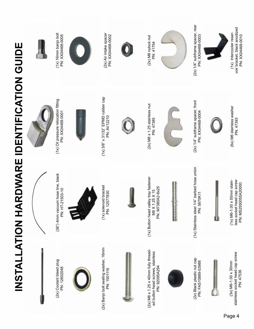
Page 4
INST
ALL
ATIO
N H
AR
DW
AR
E ID
ENTI
FIC
ATIO
N G
UID
E
(2x)
Coo
lant
ble
ed p
lug
PN
: 126
0204
8(3
6”) 4
mm
vac
uum
hos
e lin
e, b
lack
PN
: HT-
2150
3-10
(1x)
Oil
pres
sure
relo
catio
n fit
ting
P
N: X
X04
468-
0001
(1x)
16m
m b
anjo
bol
t
PN
: XX
0446
8-00
05
(2x)
Ban
jo b
olt s
ealin
g w
ashe
r, 16
mm
PN
: 150
1116
(1x)
sol
enoi
d br
acke
t
P
N: 1
2577
830
(1x)
3/8
” x 3
1/32
” EP
MD
rubb
er c
ap
PN
: AV
1221
0(2
x) A
ir in
take
spa
cer
PN
: XX
0446
8-00
02
(2x)
M8
x 1.
25 x
40m
m fu
lly th
read
-ed
but
ton
head
scr
ews,
sta
inle
ss
P
N: 9
2095
A29
4
(2x)
M8
x 1.
25 s
tain
less
nut
P
N: 4
7385
(2x)
M8
nylo
ck n
ut
PN
: 417
54
(2x)
Bla
ck p
last
ic n
ut c
ap
PN
: FA
S10
889-
0398
8(1
x) S
tain
less
ste
el 1
/4” b
arbe
d ho
se u
nion
P
N: 5
670K
11(2
x) 1
/4” s
ubfra
me
spac
er, f
ront
PN
: XX
0446
8-00
04
(2x)
1/4
” sub
fram
e sp
acer
, rea
r
PN
: XX
0446
8-00
03
(3x)
M6-
1.00
x 3
0mm
st
ainl
ess
sock
et h
ead
cap
scre
w
P
N: 4
7536
(1x)
M6-
1.00
x 5
5mm
sta
in-
less
soc
ket h
ead
cap
scre
w
PN
: MS
2550
055A
2000
0
(6x)
M6
stai
nles
s w
ashe
r
PN
: 473
93(1
x) I
nter
cool
er re
ser-
voir
brac
ket,
blac
k an
odiz
ed
PN
: XX
0446
8-00
10
(1x)
But
ton
head
val
ley
tray
fast
ener
M
8 X
1.2
5 X
15
PN
: M73
80A
2-8x
25

Page 5
(1x)
Inte
rcoo
ler p
ump
harn
ess
PN
: XX
0446
8-00
11(1
x) A
ngle
cut
inle
t hos
e
PN
: XX
0446
8-00
22
(1x)
MA
P/IA
T ad
apte
r har
ness
PN
: XX
0446
8-00
12(1
x) M
AF
adap
ter h
arne
ss, 5
pin
to 3
pin
(1
997-
2000
C5’
s)
P
N: X
X04
468-
0013
(1x)
MA
F ad
apte
r har
ness
, 5 p
in to
5 p
in
(200
1-20
04 C
5’s)
PN
: XX
0446
8-00
14
(1x)
C5
TPS
22”
ext
ensi
on h
arne
ss
PN
: L48
0060
197
(1x)
Thr
ottle
bod
y m
otor
ext
ensi
on h
arne
ss
PN
: CE
1053
20(1
x) P
CV
hos
e, 1
7” O
AL
leng
th
with
10m
m q
uick
con
nect
PN
: ED
L-15
739-
LPE
(1x)
LS
2 th
rottl
e bo
dy g
aske
t
P
N: 1
2576
549
(1x)
Inte
rcoo
ler fl
uid
rese
rvoi
r
P
N: X
X04
468-
0015
(1x)
Fen
der w
ashe
r for
inte
rcoo
ler
re
serv
oir b
rack
et
P
N: 9
1119
A15
0
(1x)
90
degr
ee 3
/4” h
ose,
36”
leg
P
N: 9
820
(1x)
M6-
1.00
x 1
6mm
hex
hea
d bo
lt,
stai
nles
s
PN
:473
13
(2x)
Alu
min
um u
nthr
eade
d sp
acer
, 3/4
” OD
, 3/4
” len
gth
P
N: 9
2510
A80
4
(1x)
2 1
/4” A
del c
lam
p
P
N: D
C-2
036
(1x)
1/4
-28
lock
nut
PN
: 635
46(1
x) 1
/4-2
8 x
1 bo
lt
PN
: 363
04(1
x) M
8-1.
25 x
20m
m b
olt
LN
: 444
54
(1x)
LS
1/LS
6/LS
2 in
take
man
i-fo
ld g
aske
t kit
(8 g
aske
ts in
kit)
PN
: MS
9243
8
(1x)
Inst
alla
tion
man
ual.
bind
er, a
nd (4
x)
tem
plat
es(2
) Ste
erin
g lin
kage
nut
s
GM
PN
: 035
3777
2
M6-
1.00
X 3
5 bo
ltP
N: A
V21
049
(6) 1
/4” S
tain
less
ste
el w
ashe
r(P
N: 3
0800
)
(1x)
LP
E d
ecal
(PN
: 920
0100
00)
Page 6
Tools & Materials Required# Description Item ID/PN
1 7-24mm socket set and ratchet (deep and standard) N/A1 Flathead screw driver N/A1 Pliers N/A1 Fuel pressure tester/bleed off tool N/A1 Fuel line removal kit N/A1 Tape N/A1 Pry tool N/A1 Electric drill N/A1 1 1/2” hole saw N/A1 1/4” drill bit N/A1 5/16” drill bit N/A1 5mm hex key N/A1 6mm hex key N/A1 Sand paper (or equivalent) N/A1 Torque wrench N/A1 Hack saw (or equivalent cutting tool) N/A1 Hand syphon N/A1 GM ball joint removal tool J421881 GM flywheel holding tool J-42386-A1 18mm wrench N/A1 1/2” wrench N/A
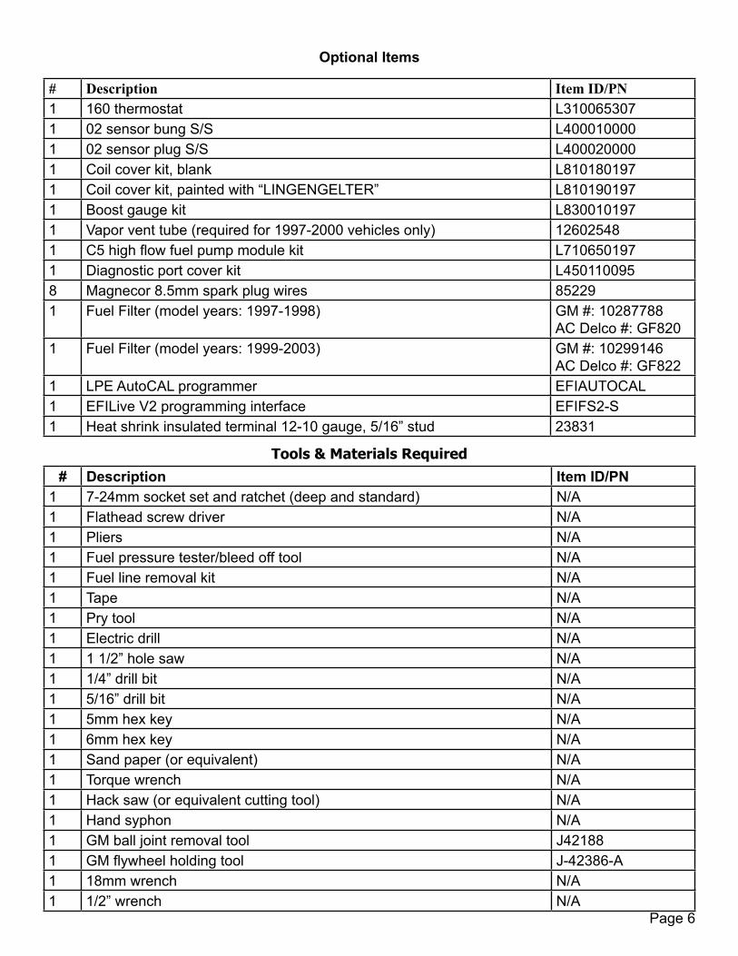
# Description Item ID/PN1 160 thermostat L3100653071 02 sensor bung S/S L4000100001 02 sensor plug S/S L4000200001 Coil cover kit, blank L8101801971 Coil cover kit, painted with “LINGENGELTER” L8101901971 Boost gauge kit L8300101971 Vapor vent tube (required for 1997-2000 vehicles only) 126025481 C5 high flow fuel pump module kit L7106501971 Diagnostic port cover kit L4501100958 Magnecor 8.5mm spark plug wires 852291 Fuel Filter (model years: 1997-1998) GM #: 10287788
AC Delco #: GF8201 Fuel Filter (model years: 1999-2003) GM #: 10299146
AC Delco #: GF8221 LPE AutoCAL programmer EFIAUTOCAL1 EFILive V2 programming interface EFIFS2-S1 Heat shrink insulated terminal 12-10 gauge, 5/16” stud 23831
Optional Items
Page 7
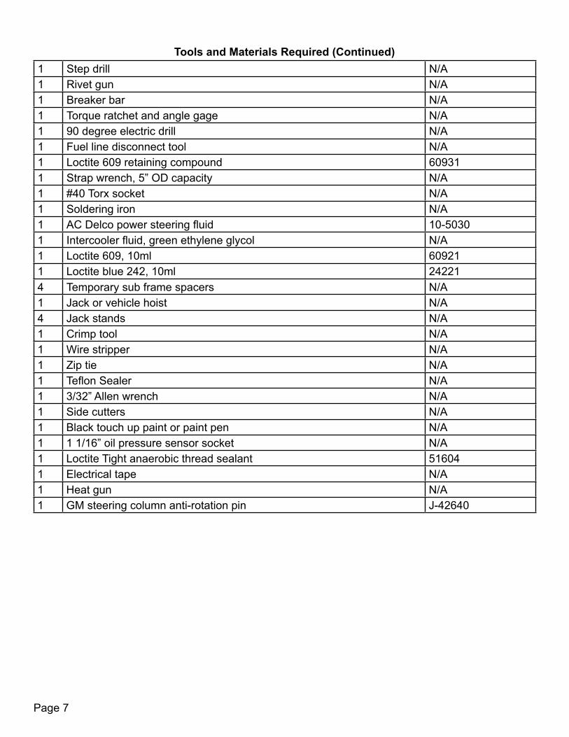
1 Step drill N/A1 Rivet gun N/A1 Breaker bar N/A1 Torque ratchet and angle gage N/A1 90 degree electric drill N/A1 Fuel line disconnect tool N/A1 Loctite 609 retaining compound 609311 Strap wrench, 5” OD capacity N/A1 #40 Torx socket N/A1 Soldering iron N/A1 AC Delco power steering fluid 10-50301 Intercooler fluid, green ethylene glycol N/A1 Loctite 609, 10ml 609211 Loctite blue 242, 10ml 242214 Temporary sub frame spacers N/A1 Jack or vehicle hoist N/A4 Jack stands N/A1 Crimp tool N/A1 Wire stripper N/A1 Zip tie N/A1 Teflon Sealer N/A1 3/32” Allen wrench N/A1 Side cutters N/A1 Black touch up paint or paint pen N/A1 1 1/16” oil pressure sensor socket N/A1 Loctite Tight anaerobic thread sealant 516041 Electrical tape N/A1 Heat gun N/A1 GM steering column anti-rotation pin J-42640
Tools and Materials Required (Continued)
Page 8
Read the entire instruction manual before beginning installation. Some stock parts will be used in reassembly.
In these installation instructions, torque specifications are given in both in-lbs and ft-lbs. Verify that the torque wrench is set to the proper setting before torquing the bolt. Failure to do so could lead to either loose bolts or to bolt heads being torqued off.
Installation of the Edelbrock E-Force supercharger on to the C5 Corvette requires permanent modification of the supercharger casing in order to provide the clearance needed.
If your vehicle has an aftermarket oil cooler installed, make sure that the heat exchanger and the oil cooler still allow sufficiant air flow to the radiator.
The E-Force supercharger will not run on the Original Equipment Manufacturer (OEM or “stock”) C5 fuel pump. The OEM Corvette C5 fuel pump does not provide enough fuel flow to maintain the correct air-to-fuel ratio. You will need to increase the fuel flow. Two recommended solutions are voltage boosting the stock fuel pump, via a Boost-a-pump kit (PN: KB89067) or changing to a high flow replacement fuel pump (PN: L710650197).
This kit requires the replacement of the OEM spark plugs as the OEM spark plugs are not designed for the high cylinder pressure and heat that is created with the addition of a supercharger. LPE recommends using LS9 spark plugs (PN: 41-104) or plugs that are equivalent in heat range.
LPE has found that valve float tends to occur on LS1 and LS6 engines when a supercharger or turbocharger is added to the engine. LPE recommends springs with higher seat loads and spring rates to overcome the problem. The recommended valve springs are listed in the Additional Required Components parts list.
Installing this supercharger will significantly increase engine performance. Due to this significant increase in performance, it is recommended that the vehicle be inspected before installation of the supercharger system to make sure the vehicle can handle the increased performance. This includes checking the clutch condition and performing leak and compression checks.
This supercharger kit requires premium fuel levels. LPE recommends using 93 octane fuel. Use the highest available octane fuel if 93 octane fuel is unavailable.
This kit is currently not designed for top post batteries. Cars equipped with top post batteries will need to be converted to a side post battery.
This kit is currently not designed for 1997-1998 model year vehicles due to fuel system differences. Additional components would be required to adapt this kit to a 1997-1998 model year vehicle. Installation of this kit requires the installation of an aftermarket hood to provide clearance for the supercharger. The OEM C5 hood does not have enough clearance under it to allow for the supercharger. LPE recommends the C5 Corvette SCIC Hood (PN: L850060197).
Page 9
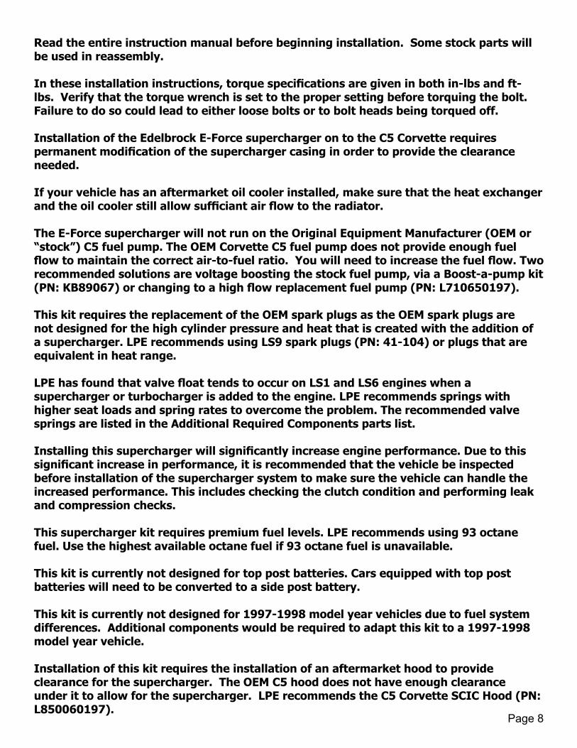
1. Open the hood. If you have been driving your vehicle, allow time for it to cool down before beginning this installation.
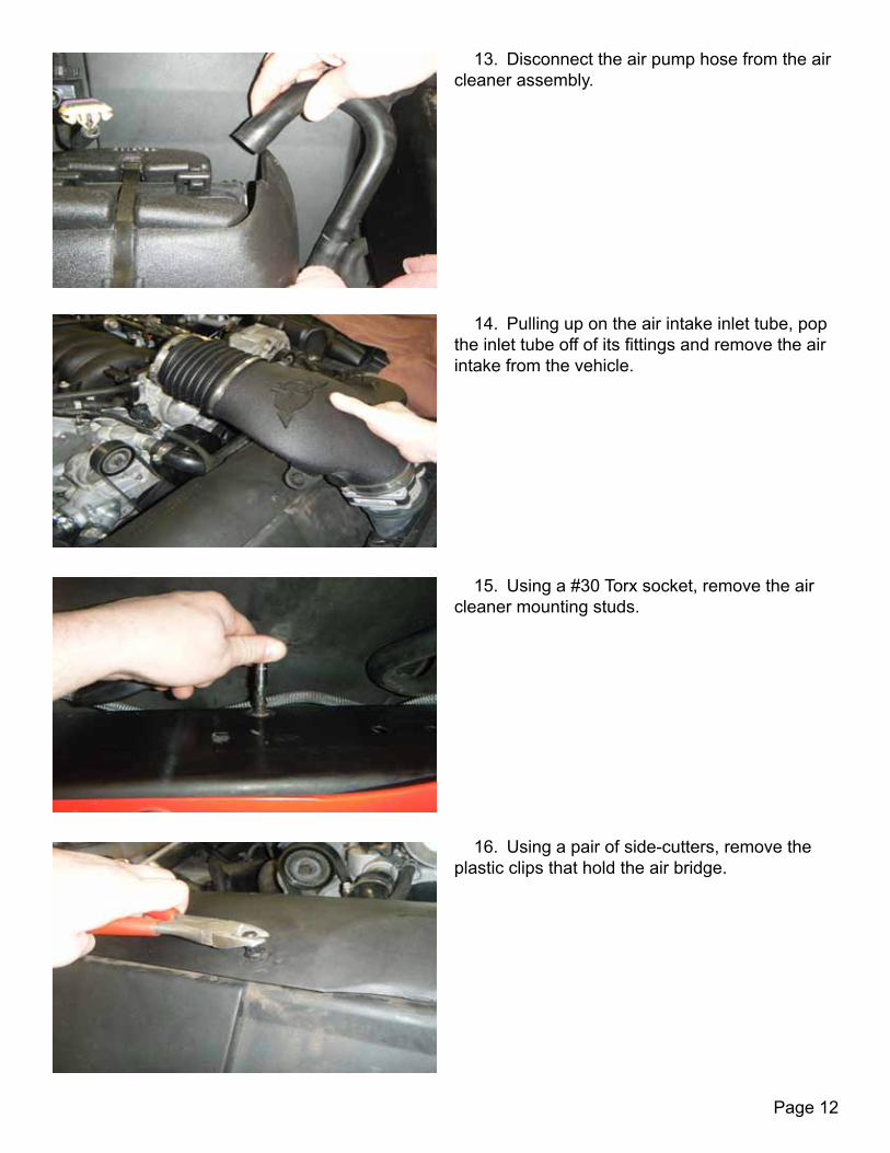
3. Using a 5/16” socket and ratchet, disconnect the negative (-) battery terminal from your battery. Tape off your terminal connection to ensure no accidental contact between the connector and the battery terminal. NOTE: The 2004 C5 has top post battery terminals. Vehicles of this model year will need to be converted to a side post battery before continuing with the installation. Use a 10mm wrench to loosen the clamp on the post battery terminal.
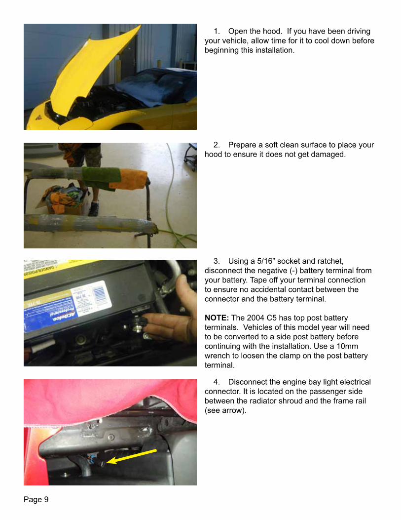
2. Prepare a soft clean surface to place your hood to ensure it does not get damaged.
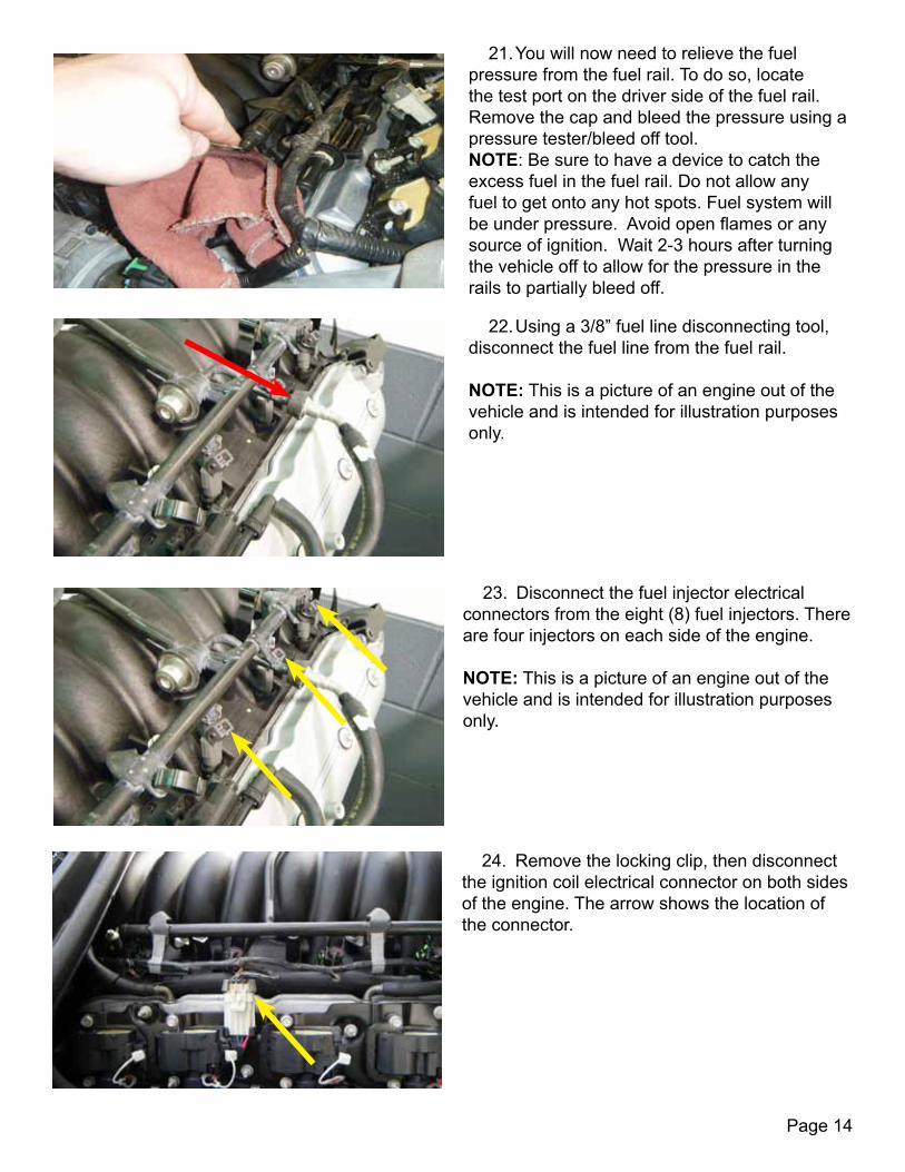
4. Disconnect the engine bay light electrical connector. It is located on the passenger side between the radiator shroud and the frame rail (see arrow).

Page 10
5. Using a small flat head screw driver, un-clip each snap fitting retainer on the hydraulic prop rods. With the clip pulled out, remove the prop rod from the snap fitting by pulling it away from the hood. There is one per side of the hood. You will need the help of an assistant to hold up the hood.
6. Using a 13mm socket and ratchet, remove the four (4) nuts holding the hood hinge to the engine bay frame. There are two (2) on each side of the vehicle. Then, with the help of an assistant, lift the hood away from the car and place it on the clean surface set up in step 2.
7. Raise the vehicle with a vehicle hoist or a jack and jackstands. Be careful to follow the GM lifting procedures on the C5 Corvette due to the aerodynamic components being easily damaged and the low ride height of the vehicle.
8. After placing jack stands under the vehicle, place a catch pan under the radiator and remove the coolant reservoir cap. Then using a 1/4” ratchet and extension, open the coolant drain valve and allow the coolant to drain completely. The following step shows the coolant drain valve. NOTE: Save the coolant to reuse after the installation is complete or dispose of the coolant in a proper manner.

Page 11
9. The adjacent picture shows the coolant drain valve (red arrow) and the coolant drain nozzle (yellow arrow). These are located directly below and to the passenger side of the radiator.
10. Using a flathead screwdriver, loosen the hose clamp shown to remove the air intake from the throttle body.
11. Disconnect the air temperature sensor. NOTE: This step only applies to 1997-2000 model year vehicles.
12. Disconnect the Mass Air Flow (MAF) sensor electrical connector.
Page 12
13. Disconnect the air pump hose from the air cleaner assembly.
14. Pulling up on the air intake inlet tube, pop the inlet tube off of its fittings and remove the air intake from the vehicle.
15. Using a #30 Torx socket, remove the air cleaner mounting studs.
16. Using a pair of side-cutters, remove the plastic clips that hold the air bridge.

Page 13
17. Remove the MAF wiring harness from the clip on the radiator shroud.
18. After removing the passenger side oil cap, remove the passenger side coil cover by pulling up and away from the engine. Once removed, re-install the oil cap and set the coil cover to the side.
19. Remove the driver side coil cover by pulling up and away from the engine. Once removed, set it to the side.
20. Remove the fuel filler cap from the car. This relieves pressure build up in the gas tank.
Page 14
22. Using a 3/8” fuel line disconnecting tool, disconnect the fuel line from the fuel rail. NOTE: This is a picture of an engine out of the vehicle and is intended for illustration purposes only.
23. Disconnect the fuel injector electrical connectors from the eight (8) fuel injectors. There are four injectors on each side of the engine. NOTE: This is a picture of an engine out of the vehicle and is intended for illustration purposes only.
21. You will now need to relieve the fuel pressure from the fuel rail. To do so, locate the test port on the driver side of the fuel rail. Remove the cap and bleed the pressure using a pressure tester/bleed off tool. NOTE: Be sure to have a device to catch the excess fuel in the fuel rail. Do not allow any fuel to get onto any hot spots. Fuel system will be under pressure. Avoid open flames or any source of ignition. Wait 2-3 hours after turning the vehicle off to allow for the pressure in the rails to partially bleed off.
24. Remove the locking clip, then disconnect the ignition coil electrical connector on both sides of the engine. The arrow shows the location of the connector.

Page 15
26. Disconnect the Throttle Position Sensor (TPS) connector from the throttle body and un-clip from the PCV hose.
25. Remove the positive crankcase ventilation (PCV) hose from the passenger side valve cover.
27. Using a 10mm socket and ratchet, remove the ground strap nut from the vapor tube stud.
28. Disconnect the EVAP solenoid electrical connector.
Page 16
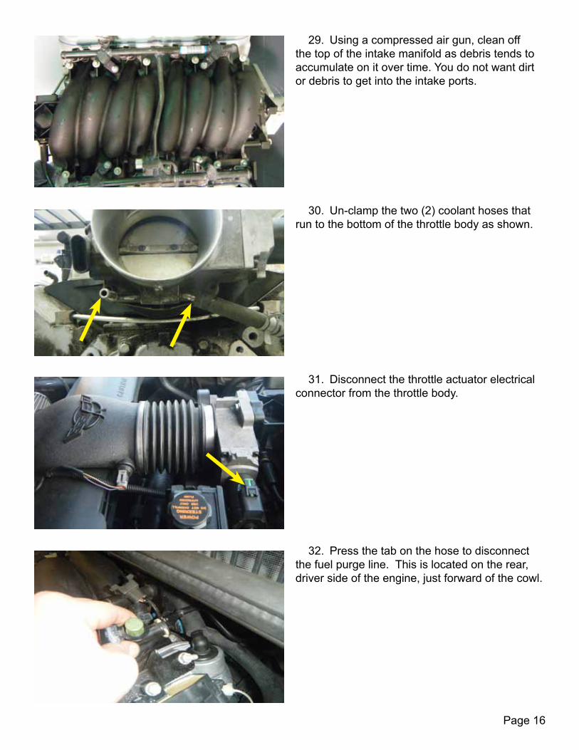
29. Using a compressed air gun, clean off the top of the intake manifold as debris tends to accumulate on it over time. You do not want dirt or debris to get into the intake ports.
30. Un-clamp the two (2) coolant hoses that run to the bottom of the throttle body as shown.
31. Disconnect the throttle actuator electrical connector from the throttle body.
32. Press the tab on the hose to disconnect the fuel purge line. This is located on the rear, driver side of the engine, just forward of the cowl.
Page 17
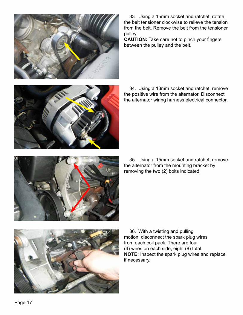
33. Using a 15mm socket and ratchet, rotate the belt tensioner clockwise to relieve the tension from the belt. Remove the belt from the tensioner pulley. CAUTION: Take care not to pinch your fingers between the pulley and the belt.
34. Using a 13mm socket and ratchet, remove the positive wire from the alternator. Disconnect the alternator wiring harness electrical connector.
35. Using a 15mm socket and ratchet, remove the alternator from the mounting bracket by removing the two (2) bolts indicated.
36. With a twisting and pulling motion, disconnect the spark plug wires from each coil pack, There are four (4) wires on each side, eight (8) total. NOTE: Inspect the spark plug wires and replace if necessary.

Page 18
37. Disconnect the brake booster hose from the power brake booster.
38. Using a 10mm deep well socket and ratchet, remove the bolts that secure the coil pack brackets. Bolts are located as shown on each side. There are five (5) on each coil pack bracket.
39. Remove the positive crankcase ventilation (PCV) hose from the back of the driver side valve cover.
40. Using an 8mm socket and ratchet, remove the ten (10) mounting bolts to the intake manifold.
Page 19
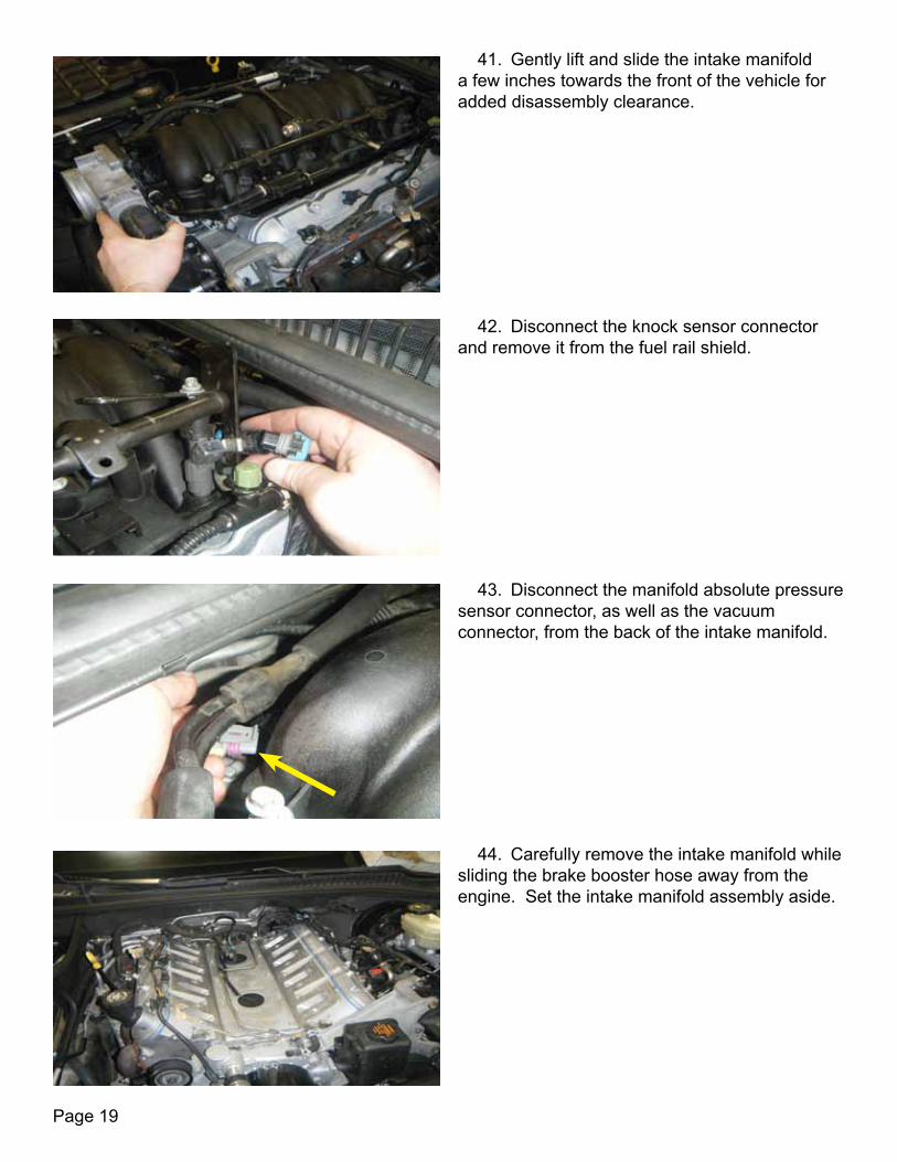
41. Gently lift and slide the intake manifold a few inches towards the front of the vehicle for added disassembly clearance.
42. Disconnect the knock sensor connector and remove it from the fuel rail shield.
43. Disconnect the manifold absolute pressure sensor connector, as well as the vacuum connector, from the back of the intake manifold.
44. Carefully remove the intake manifold while sliding the brake booster hose away from the engine. Set the intake manifold assembly aside.

Page 20
45. Vacuum any dirt in the valley area and around the intake ports. Clean the head surface with a clean rag, then tape off the cylinder head intake ports to ensure no debris enters the engine. It is very important that no dirt gets in to these ports. You may need to clean off any oil or debris using a solvent such as engine degreaser.
46. Remove the 90 degree hose from the vapor vent tube. It is very important to keep this tube as it will be re-installed at a later time. NOTE: This step is only for 1997-2000 model year vehicles.
47. Remove the knock sensor wiring harness clips from the vapor vent tube. NOTE: This step is only for 1997-2000 model year vehicles.
48. Using a 10mm socket and ratchet, remove the four (4) bolts securing the vapor vent tube to the cylinder heads and remove it. NOTE: This step is only for 1997-2000 model year vehicles. The vent tube is to be left in place for 2001-2004 vehicles.

Page 21
49. Using a 10mm socket and ratchet, remove the two (2) rear vent plugs, one on each cylinder head. NOTE: This step is for 2001-2004 model year vehicles only.
50. Dislodge the two (2) rubber plugs that cover the knock sensors. Unplug the knock sensors and remove the harness by depressing the sides of the connectors.
51. Using a 7/8” socket and ratchet, remove both of the knock sensors from the valley tray.
52. Using a 10mm socket and ratchet, remove the ten (10) bolts securing the valley plate. NOTE: The OEM valley tray must be modified or replaced with an LPE valley tray (PN:XX04468-0021). This is due to clearance issues with the supercharger. Diagram 2 on page 85 shows the modifications that need to be made to the OEM valley tray. LPE offers an OEM valley tray that is machined and ready to install in place of the factory OEM tray.

Page 22
55. Using a 1-1/16” oil pressure sensor socket, remove the sensor from the engine block.
54. Pulling upward, un-clip the oil pressure sensor.
1
26
5
4
3
7
8
9
10
ABZ 12/27/11
N/A 01:1
N/A
N/A
C5 E-FORCE VALLEY TRAY BOLTTORQUE PATTERN
N/ASCALE:
SIZE DWG. NO.
AREV.
MATERIAL
FINISH
DO NOT SCALE DRAWINGAPPLICATION
USED ONNEXT ASSY
DIMENSIONS ARE IN INCHESTOLERANCES:ANGULAR: MACH 0.5ONE PLACE DECIMAL 0.2*TWO PLACE DECIMAL 0.01*THREE PLACE DECIMAL 0.005**UNLESS STATED OTHERWISE
NAME DATE
DRAWN
CHECKED
ENG APPR.
MFG APPR.
Q.A.
SHEET 1 OF 1WEIGHT:
COMMENTS:
REVISIONS
DESCRIPTIONREV. DATE APPROVED
THE INFORMATION CONTAINED IN THISDRAWING IS THE SOLE PROPERTY OFLINGENFELTER PERFORMACE ENGINEERING.ANY REPRODUCTION IN PART OR AS A WHOLEWITHOUT THE WRITTEN PERMISSION OFLINGENFELTER PERFORMACE ENGINEERINGIS PROHIBITED.
PROPRIETARY AND CONFIDENTIAL
DWG. NAME
53. Once removed, install the new valley plate using the supplied bolts (9 countersunk socket head bolts from the Edelbrock kit and 1 M8 X 1.25X 25 button head bolt on the ‘additional required components’ list) and gasket using a 5mm Allen socket. The button head bolt (PN: M7380A2-8x25) is installed in the location marked by the red arrow below. The ten (10) valley tray bolts are torqued to 15 ft-lbs. Reference the following drawing for the bolt torque pattern. CAUTION: Take care not to over-torque the valley tray bolts. By over-torquing the bolts, you risk cracking the cast aluminum valley cover.

Page 23
56. Using teflon sealant, install the oil pressure sensor into the new adaptor fitting (which consists of an oil pressure relocation fitting (PN: XX04468-0001), M16 X 1.5 Banjo Bolt (PN: XX04468-0005), and two (2) banjo bolt sealing washers (PN: 1501116). The yellow arrow denotes where the oil pressure sensor is to be installed in to the relocation fitting. Torque oil pressure sensor to 15 ft-lbs.
57. Plug the oil pressure sensor assembly back into the connector.
58. Using a 7/8” socket, screw in and tighten the banjo bolt into the engine block. Torque the bolt to 15 ft-lbs.
59. Using a rivet gun, install the supplied coolant bleed plugs (PN: 12602048) in the two (2) rear water line manifold holes. This provides a seal that is permanent and the clearance needed for the supercharger. CAUTION: Do not let the coolant bleed plugs fall into the water line holes. They can be extremely difficult to retrieve if dropped.

Page 24
61. Reinstall the knock sensors. These are torqued to 15 ft-lbs. CAUTION: Take care not to drop, damage, or over-torque the knock sensors.
60. This illustration shows which hole on each side needs to be plugged by the coolant bleed plugs. Be sure to plug the non-threaded holes.
62. Remove the clips, as well as the tape from knock sensor harness. Remove the loom from the rear sensor wire.
63. Use tape to hold the knock sensor harness into the machined groove in the valley tray. Route the connector under the A.I.R. tube and connect to the engine harness. CAUTION: Take care not to pinch or damage the knock sensor harness wires.

Page 25
65. Remove the 90 degree elbow attached to the vacuum line at the rear of the engine.
64. Using a 5/8” spark plug socket, remove the stock spark plugs and replace with the proper heat range spark plugs. LPE recommends AC Delco LS7/LS9 spark plugs (PN: 41-104). Torque the new spark plugs to 11ft-lbs, then reinstall the spark plug wires onto the spark plugs.
66. Spray a small amount of lubricant into the end of the black vacuum hose provided and slide it onto the plastic fitting roughly two inches.
67. Route the hose towards the driver side of the engine block and out of the way until ready to install other end of the hose.
Page 26
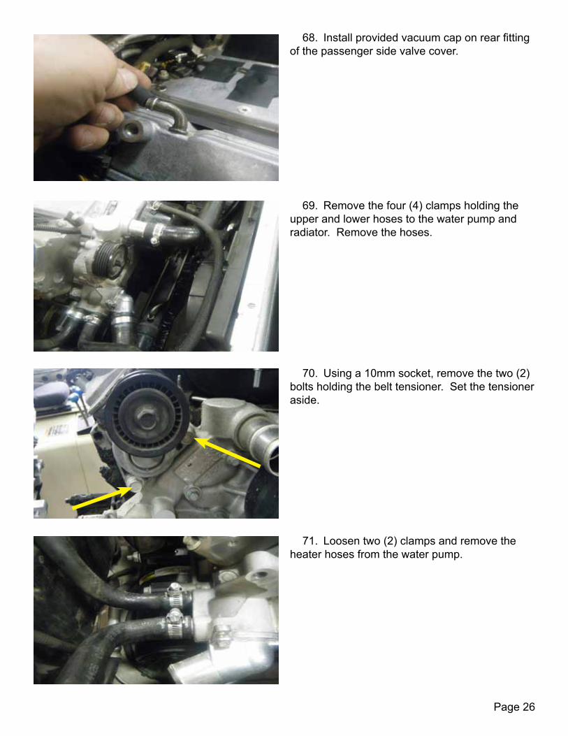
68. Install provided vacuum cap on rear fitting of the passenger side valve cover.
69. Remove the four (4) clamps holding the upper and lower hoses to the water pump and radiator. Remove the hoses.
70. Using a 10mm socket, remove the two (2) bolts holding the belt tensioner. Set the tensioner aside.
71. Loosen two (2) clamps and remove the heater hoses from the water pump.
Page 27
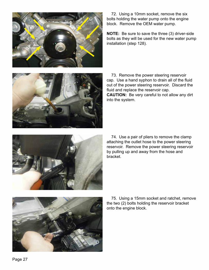
72. Using a 10mm socket, remove the six bolts holding the water pump onto the engine block. Remove the OEM water pump. NOTE: Be sure to save the three (3) driver-side bolts as they will be used for the new water pump installation (step 128).
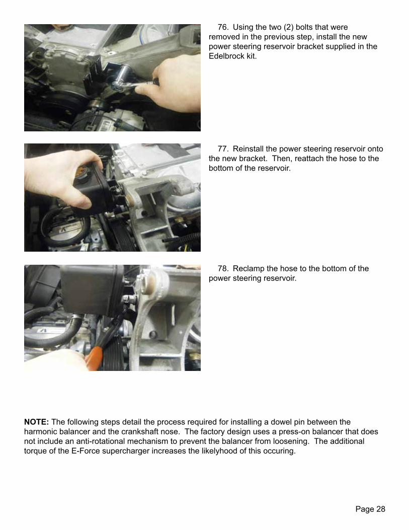
73. Remove the power steering reservoir cap. Use a hand syphon to drain all of the fluid out of the power steering reservoir. Discard the fluid and replace the reservoir cap. CAUTION: Be very careful to not allow any dirt into the system.
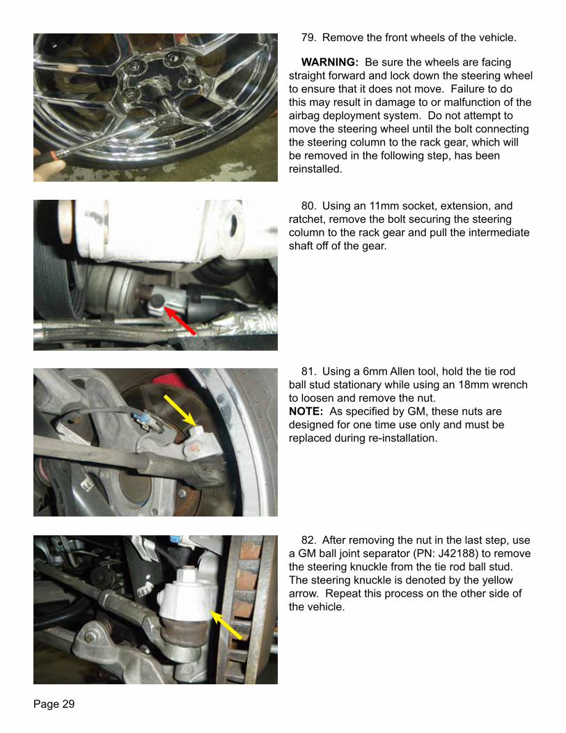
74. Use a pair of pliers to remove the clamp attaching the outlet hose to the power steering reservoir. Remove the power steering reservoir by pulling up and away from the hose and bracket.
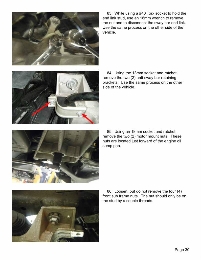
75. Using a 15mm socket and ratchet, remove the two (2) bolts holding the reservoir bracket onto the engine block.
Page 28
76. Using the two (2) bolts that were removed in the previous step, install the new power steering reservoir bracket supplied in the Edelbrock kit.
77. Reinstall the power steering reservoir onto the new bracket. Then, reattach the hose to the bottom of the reservoir.
NOTE: The following steps detail the process required for installing a dowel pin between the harmonic balancer and the crankshaft nose. The factory design uses a press-on balancer that does not include an anti-rotational mechanism to prevent the balancer from loosening. The additional torque of the E-Force supercharger increases the likelyhood of this occuring.
78. Reclamp the hose to the bottom of the power steering reservoir.
Page 29
WARNING: Be sure the wheels are facing straight forward and lock down the steering wheel to ensure that it does not move. Failure to do this may result in damage to or malfunction of the airbag deployment system. Do not attempt to move the steering wheel until the bolt connecting the steering column to the rack gear, which will be removed in the following step, has been reinstalled.
79. Remove the front wheels of the vehicle.
80. Using an 11mm socket, extension, and ratchet, remove the bolt securing the steering column to the rack gear and pull the intermediate shaft off of the gear.
81. Using a 6mm Allen tool, hold the tie rod ball stud stationary while using an 18mm wrench to loosen and remove the nut. NOTE: As specified by GM, these nuts are designed for one time use only and must be replaced during re-installation.
82. After removing the nut in the last step, use a GM ball joint separator (PN: J42188) to remove the steering knuckle from the tie rod ball stud. The steering knuckle is denoted by the yellow arrow. Repeat this process on the other side of the vehicle.
Page 30
83. While using a #40 Torx socket to hold the end link stud, use an 18mm wrench to remove the nut and to disconnect the sway bar end link. Use the same process on the other side of the vehicle.
84. Using the 13mm socket and ratchet, remove the two (2) anti-sway bar retaining brackets. Use the same process on the other side of the vehicle.
85. Using an 18mm socket and ratchet, remove the two (2) motor mount nuts. These nuts are located just forward of the engine oil sump pan.
86. Loosen, but do not remove the four (4) front sub frame nuts. The nut should only be on the stud by a couple threads.
Page 31
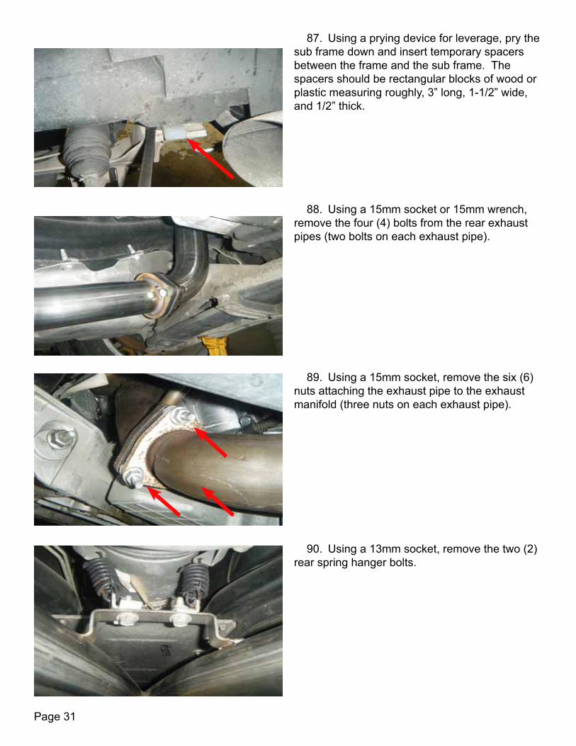
87. Using a prying device for leverage, pry the sub frame down and insert temporary spacers between the frame and the sub frame. The spacers should be rectangular blocks of wood or plastic measuring roughly, 3” long, 1-1/2” wide, and 1/2” thick.
88. Using a 15mm socket or 15mm wrench, remove the four (4) bolts from the rear exhaust pipes (two bolts on each exhaust pipe).
89. Using a 15mm socket, remove the six (6) nuts attaching the exhaust pipe to the exhaust manifold (three nuts on each exhaust pipe).
90. Using a 13mm socket, remove the two (2) rear spring hanger bolts.
Page 32
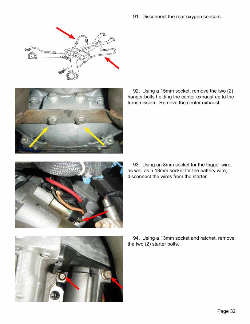
91. Disconnect the rear oxygen sensors.
92. Using a 15mm socket, remove the two (2) hanger bolts holding the center exhaust up to the transmission. Remove the center exhaust.
93. Using an 8mm socket for the trigger wire, as well as a 13mm socket for the battery wire, disconnect the wires from the starter.
94. Using a 13mm socket and ratchet, remove the two (2) starter bolts.
Page 33
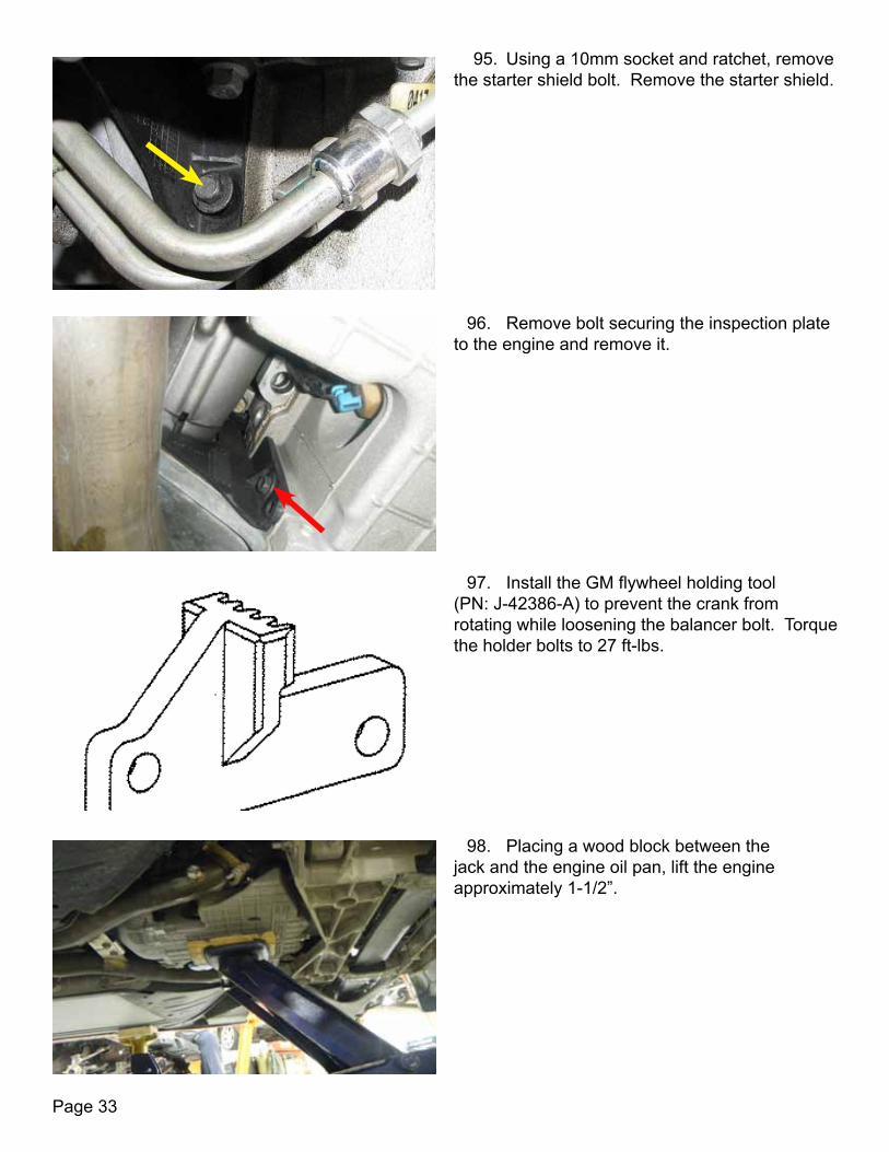
96. Remove bolt securing the inspection plate to the engine and remove it.
95. Using a 10mm socket and ratchet, remove the starter shield bolt. Remove the starter shield.
97. Install the GM flywheel holding tool (PN: J-42386-A) to prevent the crank from rotating while loosening the balancer bolt. Torque the holder bolts to 27 ft-lbs.
98. Placing a wood block between the jack and the engine oil pan, lift the engine approximately 1-1/2”.
Page 34
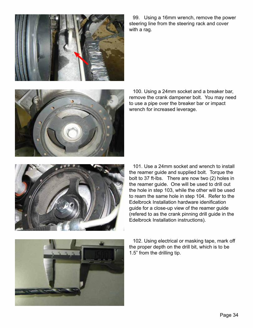
99. Using a 16mm wrench, remove the power steering line from the steering rack and cover with a rag.
100. Using a 24mm socket and a breaker bar, remove the crank dampener bolt. You may need to use a pipe over the breaker bar or impact wrench for increased leverage.
101. Use a 24mm socket and wrench to install the reamer guide and supplied bolt. Torque the bolt to 37 ft-lbs. There are now two (2) holes in the reamer guide. One will be used to drill out the hole in step 103, while the other will be used to ream the same hole in step 104. Refer to the Edelbrock Installation hardware idenification guide for a close-up view of the reamer guide (refered to as the crank pinning drill guide in the Edelbrock Installation instructions).
102. Using electrical or masking tape, mark off the proper depth on the drill bit, which is to be 1.5” from the drilling tip.
Page 35
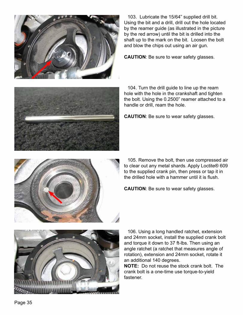
103. Lubricate the 15/64” supplied drill bit. Using the bit and a drill, drill out the hole located by the reamer guide (as illustrated in the picture by the red arrow) until the bit is drilled into the shaft up to the mark on the bit. Loosen the bolt and blow the chips out using an air gun. CAUTION: Be sure to wear safety glasses.
105. Remove the bolt, then use compressed air to clear out any metal shards. Apply Loctite® 609 to the supplied crank pin, then press or tap it in the drilled hole with a hammer until it is flush. CAUTION: Be sure to wear safety glasses.
104. Turn the drill guide to line up the ream hole with the hole in the crankshaft and tighten the bolt. Using the 0.2500” reamer attached to a handle or drill, ream the hole. CAUTION: Be sure to wear safety glasses.
106. Using a long handled ratchet, extension and 24mm socket, install the supplied crank bolt and torque it down to 37 ft-lbs. Then using an angle ratchet (a ratchet that measures angle of rotation), extension and 24mm socket, rotate it an additional 140 degrees. NOTE: Do not reuse the stock crank bolt. The crank bolt is a one-time use torque-to-yield fastener.
Page 36
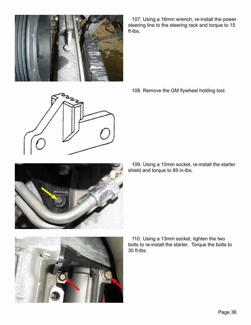
107. Using a 16mm wrench, re-install the power steering line to the steering rack and torque to 15 ft-lbs.
108. Remove the GM flywheel holding tool.
109. Using a 10mm socket, re-install the starter shield and torque to 89 in-lbs.
110. Using a 13mm socket, tighten the two bolts to re-install the starter. Torque the bolts to 30 ft-lbs.
Page 37
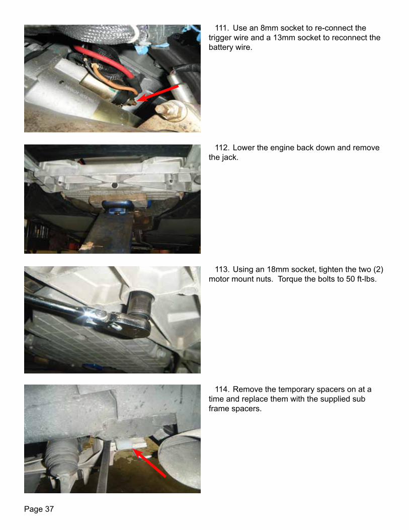
111. Use an 8mm socket to re-connect the trigger wire and a 13mm socket to reconnect the battery wire.
112. Lower the engine back down and remove the jack.
113. Using an 18mm socket, tighten the two (2) motor mount nuts. Torque the bolts to 50 ft-lbs.
114. Remove the temporary spacers on at a time and replace them with the supplied sub frame spacers.

Page 38
115. This illustration shows how the rear engine cradle spacers are installed.
116. This illustration shows how the front engine cradle spacers are installed.
117. Tighten the four (4) engine cradle nuts. Torque the engine cradle mounting nuts to 81 ft-lbs.
118. Using a 13mm socket, tighten the retaining bracket bolts to reinstall the sway bar. Torque the bolts to 35 ft-lbs. Repeat this step for the other side of the vehicle.

Page 39
119. Using a #40 Torx socket to hold the end stud, tighten the nut with an 18mm wrench to re-install the end-links. Torque the bolts to 35 ft-lbs.
120. Using a 6mm Allen tool and a 18mm wrench, re-attach the tie rod ends to the the control arm. Torque these nuts to 22 ft-lbs, then rotate the nuts an additional 120 degrees. CAUTION: The tie rod end nuts are designed for one time use, so make sure to replace the nuts during re-installation. Failure to do so could result in the failure of the nut.
121. Re-attach the steering column to the gear and install the bolt using an 11mm socket and ratchet. Torque this bolt to 20 ft-lbs. Take care not to move the steering wheel.
122. Re-install the exhaust H-pipe, support first by locating and starting the six (6) nut positions on the exhaust manifold (three nuts on each side). NOTE: Do not tighten the manifold nuts until after the front hanger is re-installed.
Page 40
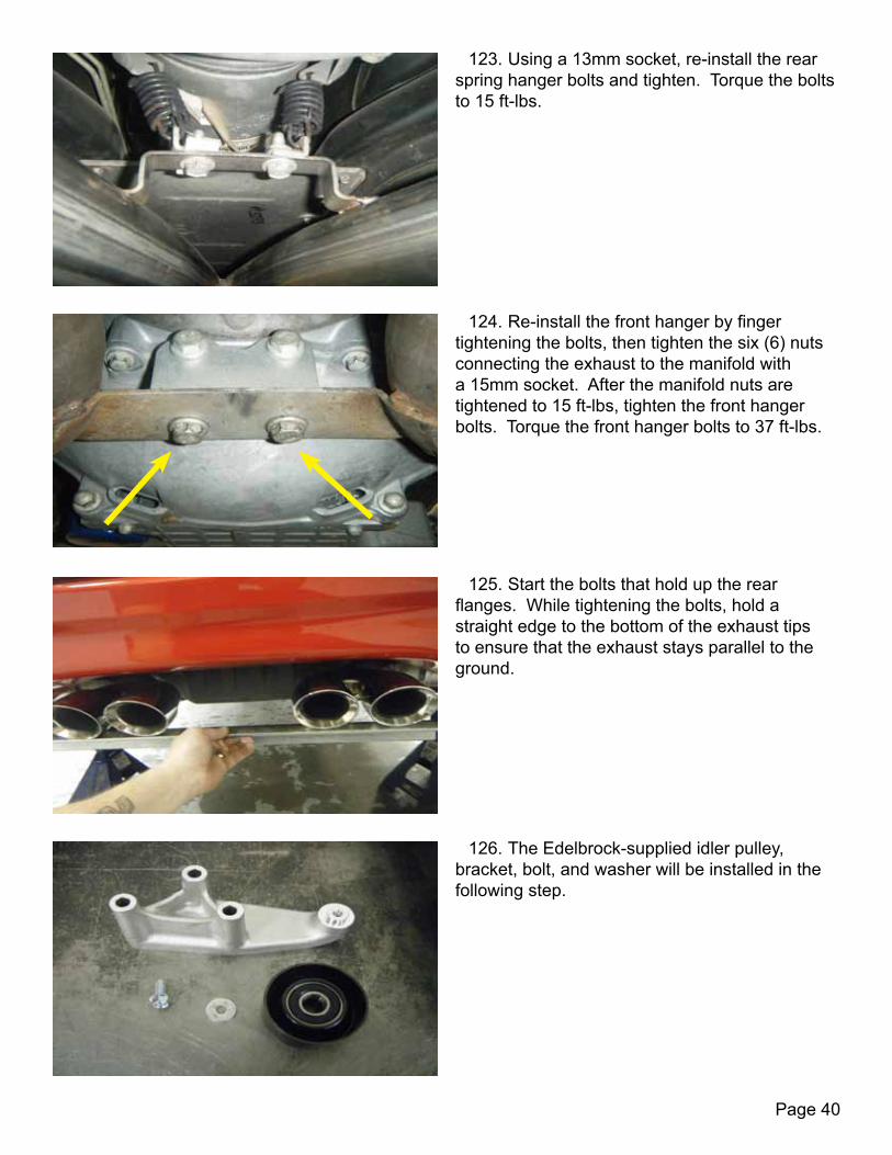
123. Using a 13mm socket, re-install the rear spring hanger bolts and tighten. Torque the bolts to 15 ft-lbs.
124. Re-install the front hanger by finger tightening the bolts, then tighten the six (6) nuts connecting the exhaust to the manifold with a 15mm socket. After the manifold nuts are tightened to 15 ft-lbs, tighten the front hanger bolts. Torque the front hanger bolts to 37 ft-lbs.
125. Start the bolts that hold up the rear flanges. While tightening the bolts, hold a straight edge to the bottom of the exhaust tips to ensure that the exhaust stays parallel to the ground.
126. The Edelbrock-supplied idler pulley, bracket, bolt, and washer will be installed in the following step.
Page 41
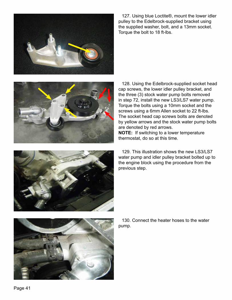
127. Using blue Loctite®, mount the lower idler pulley to the Edelbrock-supplied bracket using the supplied washer, bolt, and a 13mm socket. Torque the bolt to 18 ft-lbs.
128. Using the Edelbrock-supplied socket head cap screws, the lower idler pulley bracket, and the three (3) stock water pump bolts removed in step 72, install the new LS3/LS7 water pump. Torque the bolts using a 10mm socket and the screws using a 6mm Allen socket to 22 ft-lbs. The socket head cap screws bolts are denoted by yellow arrows and the stock water pump bolts are denoted by red arrows. NOTE: If switching to a lower temperature thermostat, do so at this time.
129. This illustration shows the new LS3/LS7 water pump and idler pulley bracket bolted up to the engine block using the procedure from the previous step.
130. Connect the heater hoses to the water pump.

Page 42
131. Using the two (2) stock tensioner bolts and the supplied socket head cap screw, install the new tensioner bracket with an 8mm Allen socket and a 15mm socket. The stock tensioner bolts are denoted by red arrows and the socket head cap screw position is denoted with a yellow arrow. Torque the bolts to 37 ft-lbs.
132. Using blue Loctite® and a 12mm socket, install the idler on to the tensioner bracket using a M8-1.25 X 20mm bolt (PN: 44454) supplied in the LPE kit. Torque the bolt to 18 ft-lbs.
133. Using a 15mm socket, tighten the Edelbrock-supplied bolt to install the new tensioner. Torque the bolt to 37 ft-lbs.
134. Connect the upper radiator hose and re-install the OEM clamps using spring-loaded clamp pliers.
Page 43
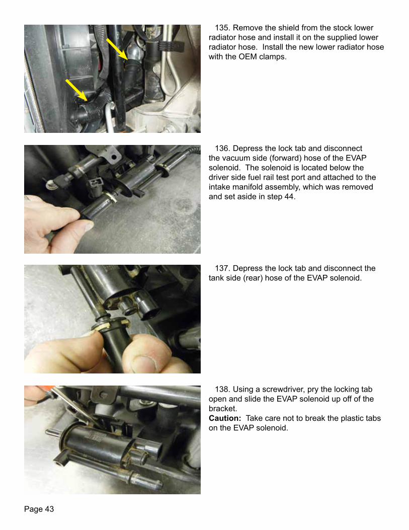
135. Remove the shield from the stock lower radiator hose and install it on the supplied lower radiator hose. Install the new lower radiator hose with the OEM clamps.
136. Depress the lock tab and disconnect the vacuum side (forward) hose of the EVAP solenoid. The solenoid is located below the driver side fuel rail test port and attached to the intake manifold assembly, which was removed and set aside in step 44.
137. Depress the lock tab and disconnect the tank side (rear) hose of the EVAP solenoid.
138. Using a screwdriver, pry the locking tab open and slide the EVAP solenoid up off of the bracket. Caution: Take care not to break the plastic tabs on the EVAP solenoid.

Page 44
139. Install the EVAP solenoid removed in the previous step on to the new LPE-supplied bracket. Using a 12mm socket and a bolt supplied in the Edelbrock kit, bolt the solenoid assembly to the back of the tensioner bracket.
140. Remove the PCV valve from the stock hose. Inspect the valve to make sure that it functions properly.
141. Install the good PCV valve (or new valve if the stock valve does not function properly) into the grommet on the rear of the driver-side valve cover.
142. Using a pair of pliers, remove the clamp and brake booster check valve from the stock hose.

Page 45
144. Install two (2) of the Edelbrock-supplied button head cap screws (found in bag #5) into the passenger side front intake bolt hole and driver side rear intake bolt hole. Use an anaerobic thread sealant, such as Loctite® Tight Multipurpose Anaerobic Gel, and a 4mm allen socket to tighten. Torque the screws to 89 in-lbs. See the following step for clarification of the locations of the intake bolt holes.
143. Insert the check valve into the brake booster.
145. This illustration shows the locations of the two intake bolt holes that were plugged with button head cap screws in the previous step.
146. For 1997-2000 model year vehicles, Install the new vent tube (PN: 12602548) in the front holes using the stock bolts. Using a 10mm socket, tighten to 106 in-lbs. NOTE: For 2001-2004 model year vehicles, leave the OEM vent tube in place.

Page 46
147. Install the stock 90 degree bypass hose on the new vapor vent tube, which is denoted with a red arrow. Then, connect the 90 degree bypass hose to the radiator hose using the supplied hose joiner (PN: 5670K11), denoted by a yellow arrow
148. Locate the the red wire with the inline fuse. Cut the wire just before the inline fuse, as shown by the yellow line in the illustration.
149. Strip the same red wire roughly 3/8”. This wire will provide the input to the Boost-A-Pump Module. Label the wire with tape to make sure that the wires do not get switched when splicing the Boost-A-Pump into the fuel pump circuit.
NOTE: Steps 148-174 and 234-238 detail the installation of the Boost-A-Pump fuel pump voltage booster. If you have installed a high flow fuel pump so that fuel pump voltage boosting is unnecessary, these steps may be skipped. The following procedure for the modification of the fuel pump voltage booster wiring is intended for use on the Kenne Bell 20 Amp Boost-A-Pump only. The installation of any other fuel pump voltage boosting device will require a different procedure. One of the modifications that LPE makes in the following instructions involves setting the Boost-A-Pump to a fixed voltage setting instead of using the variable voltage dial controller. In LPE testing, the OEM fuel pump delivered the required fuel flow when the Boost-A-Pump was set to the maximum voltage setting, which is 17 volts. This allows the Boost-A-Pump to fully boost the voltage anytime that the engine reaches the necessary boost level to trigger the pressure switch.WARNING: LPE does not recommend voltage boosting the pump above 17 volts. CARRY A SPARE 30 AMP FUSE WITH YOU AT ALL TIMES!!! If the fuse blows, the fuel pump will no longer work and your vehicle will no longer run.
Page 47
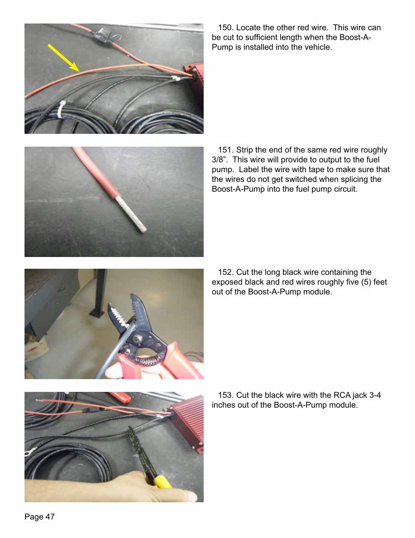
150. Locate the other red wire. This wire can be cut to sufficient length when the Boost-A-Pump is installed into the vehicle.
151. Strip the end of the same red wire roughly 3/8”. This wire will provide to output to the fuel pump. Label the wire with tape to make sure that the wires do not get switched when splicing the Boost-A-Pump into the fuel pump circuit.
152. Cut the long black wire containing the exposed black and red wires roughly five (5) feet out of the Boost-A-Pump module.
153. Cut the black wire with the RCA jack 3-4 inches out of the Boost-A-Pump module.

Page 48
154. Strip the wire shield from the wire cut in the previous step. Strip 3/8” of insulation off of the smaller black and red wires.
155. Slide heat shink tube onto one of the smaller wires that were exposed in the previous step. Twist the exposed ends of the wires together, then solder the black and red wires together. Slide the heat shrink tube over the solder joint and heat to shrink the insulation.
156. Remove the four (4) screws that secure the side cover of the Boost-A-Pump module. The correct side cover to remove is the side from which the wires exit the module.
157. Pull the soldered black and red wires through the hole and tuck them into the under the side cover. Re-install the screws and tighten.
Page 49
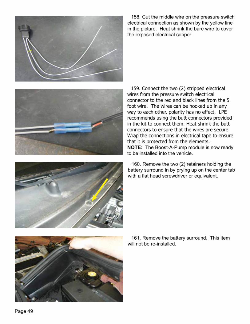
158. Cut the middle wire on the pressure switch electrical connection as shown by the yellow line in the picture. Heat shrink the bare wire to cover the exposed electrical copper.
159. Connect the two (2) stripped electrical wires from the pressure switch electrical connector to the red and black lines from the 5 foot wire. The wires can be hooked up in any way to each other, polarity has no effect. LPE recommends using the butt connectors provided in the kit to connect them. Heat shrink the butt connectors to ensure that the wires are secure. Wrap the connections in electrical tape to ensure that it is protected from the elements. NOTE: The Boost-A-Pump module is now ready to be installed into the vehicle.
160. Remove the two (2) retainers holding the battery surround in by prying up on the center tab with a flat head screwdriver or equivalent.
161. Remove the battery surround. This item will not be re-installed.
Page 50
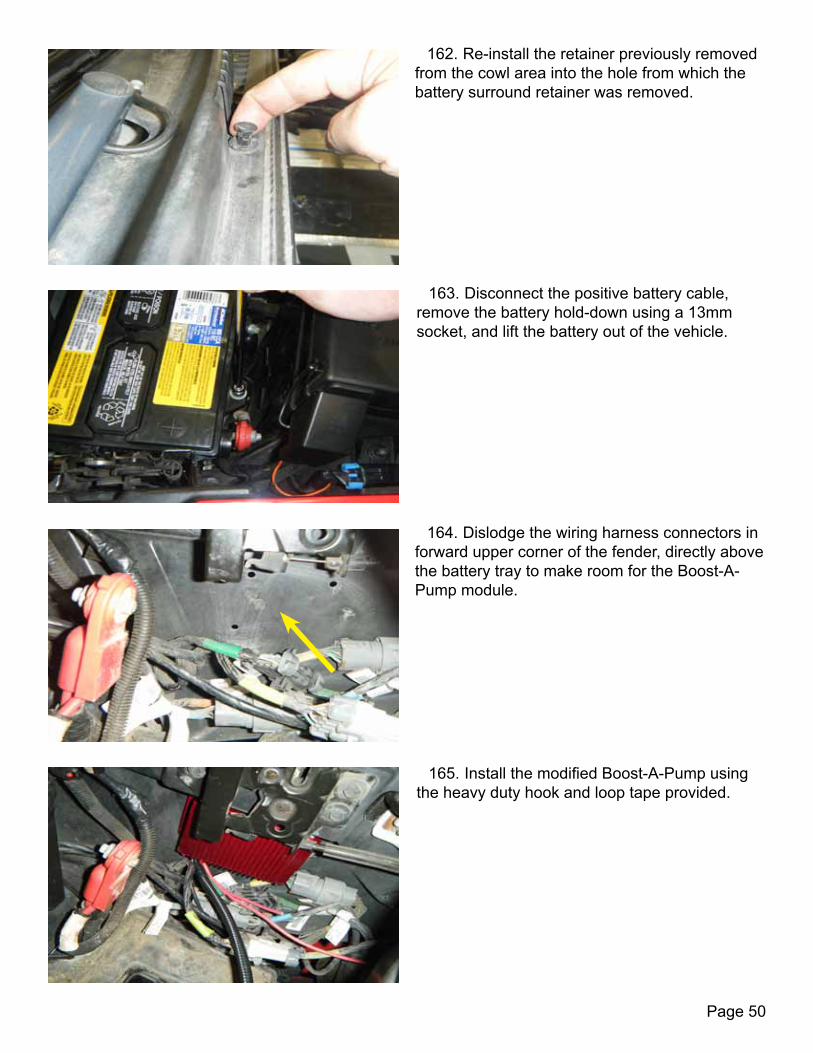
162. Re-install the retainer previously removed from the cowl area into the hole from which the battery surround retainer was removed.
163. Disconnect the positive battery cable, remove the battery hold-down using a 13mm socket, and lift the battery out of the vehicle.
164. Dislodge the wiring harness connectors in forward upper corner of the fender, directly above the battery tray to make room for the Boost-A-Pump module.
165. Install the modified Boost-A-Pump using the heavy duty hook and loop tape provided.
Page 51
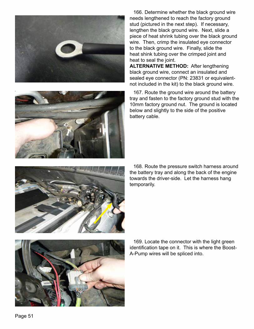
166. Determine whether the black ground wire needs lengthened to reach the factory ground stud (pictured in the next step). If necessary, lengthen the black ground wire. Next, slide a piece of heat shrink tubing over the black ground wire. Then, crimp the insulated eye connector to the black ground wire. Finally, slide the heat shink tubing over the crimped joint and heat to seal the joint. ALTERNATIVE METHOD: After lengthening black ground wire, connect an insulated and sealed eye connector (PN: 23831 or equivalent-not included in the kit) to the black ground wire.
167. Route the ground wire around the battery tray and fasten to the factory ground stud with the 10mm factory ground nut. The ground is located below and slightly to the side of the positive battery cable.
168. Route the pressure switch harness around the battery tray and along the back of the engine towards the driver-side. Let the harness hang temporarily.
169. Locate the connector with the light green identification tape on it. This is where the Boost-A-Pump wires will be spliced into.

Page 52
170. Remove the tape from the female side of the harness connector.
171. Remove the heavy gray wire (the fuel pump relay power wire) from pin C and cut it about halfway to the harness break-out.
172. Cut the Boost-A-Pump input wire to sufficient length and slide a 2” piece of heat shrink tubing on to it. Then, take the part of the grey wire still attached to the connector and solder it to the input wire of the Boost-A-Pump. Finally, slide the heat shrink tube on to the solder joint and heat the tubing to seal the joint.
173. Cut the Boost-A-Pump output wire to sufficient length and slide a 2” piece of heat shrink tubing on to the Boost-A-Pump output wire. Then, solder the output wire of the Boost-A-Pump to the other part of the gray wire going back into the harness. Slide the shrink wrap tubing over the solder joint and heat the tubing to seal the joint. Finally, cover the harness wires with elecrical insulation tape to hold them together.

Page 53
174. Re-install the battery. Tighten the hold down with a 13mm socket. CAUTION: Do not reconnect the battery cables until installation is complete.
175. OPTIONAL STEP: Using a 10mm socket, remove the two (2) bolts holding the middle air deflectors in place. This provides additional room for the installation to take place.
176. Using a 7mm socket, remove the seven (7) screws securing the radiator shroud.
177. Disconnect the outside temperature sensor electrical connector located on the passenger side of the radiator shroud near the hood light electrical connector.

Page 54
178. Using a 10mm socket, ratchet, and extension, remove the four (4) bolts holding the top radiator shroud in place. They are located in the front of the driver and passenger sides of the engine bay.
179. Using a pry tool (or equivalent), remove the two (2) radiator shroud clips located on the top side of the radiator shroud on each side. Take care not to break these clips as they will be re-used later in the installation process.
180. Carefully pull straight up on the radiator shroud and remove it from the vehicle.
181. Label the templates as passenger side or driver side, then cut them out along the lines. Using the supplied templates, hold onto the inside of the shroud and mark the mounting holes for the heat exchanger. Make sure you are using the proper template for each side of the radiator shroud.

Page 55
182. Using a drill, 1.5” hole saw, 1/4” drill bit, and the supplied templates, drill out the 1.5” hole and 0.25” hole on each side of the radiator shroud. Each template is marked as to which side it refers to. After the holes are bored out, remove the burrs using a razor blade.
183. Using a metal cutting tool such as a hacksaw or cut-off wheel, cut the heat exchanger bracket shown in the illustration. Try to make the cut as flush with the top of the heat exchanger as possible. Take care not to damage the body of the heat exchanger. Make sure to paint where the bracket was removed to ensure that is sealed from the elements.
184. Using blue Loctite®, install the heat exchanger into the shroud with the bolts and spacers provided. Steps 185-188 detail this process.
185. Place the supplied aluminum spacers between the shroud and the heat exchanger as shown. There is one spacer for each side of the exchanger.

Page 56
186. Using a 10mm socket and ratchet, install the passenger side heat exchanger LPE-supplied mounting bolt (PN: AV21049). NOTE: The use of a washer in mounting the heat exchanger to the radiator shroud, as shown in the adjacent picture, is optional. These washers are not included in the kit.
187. Using a 10mm socket and ratchet, install the driver side heat exchanger mounting bolt. The yellow arrow denotes the bolt’s location. NOTE: The use of a washer in mounting the heat exchanger to the radiator shroud, as shown in the adjacent picture, is optional. These washers are not included in the kit.
188. Install the Edelbrock-supplied heat exchanger hose assembly on to the driver side of the heat exchanger as shown.
189. Re-install the shroud and secure with the seven (7) factory screws previously removed in step 176.
Page 57
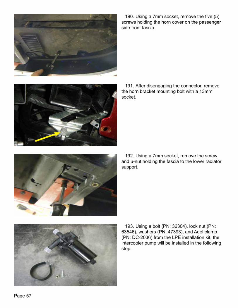
190. Using a 7mm socket, remove the five (5) screws holding the horn cover on the passenger side front fascia.
191. After disengaging the connector, remove the horn bracket mounting bolt with a 13mm socket.
192. Using a 7mm socket, remove the screw and u-nut holding the fascia to the lower radiator support.
193. Using a bolt (PN: 36304), lock nut (PN: 63546), washers (PN: 47393), and Adel clamp (PN: DC-2036) from the LPE installation kit, the intercooler pump will be installed in the following step.

Page 58
194. The intercooler will be mounted to the lower radiator support from which the screw was removed in step 192, denoted in the illustration by the red arrow. Check to ensure that the exit tube is facing upwards and that the pump inlet barb is facing towards the rear of the vehicle.
195. Using the 90 degree hose (PN: 9820) supplied in the LPE installation kit, trim the hose to a sufficient length that allows the hose to connect to both the water pump and the heat exchanger. Install on the outlet of the water pump to the heat exchanger. Use two (2) of the supplied spring clamps from the E-force kit to secure the hose to the water pump and heat exchanger.
196. Using a 10mm deep socket, mount the intercooler pump harness (PN: XX04468-0011) ground wire to the stud using the factory nut. Torque the nut to 65 in-lbs. The stud is located on the frame in front of the passenger side wheel well. Diagram 1 on page 84 illustrates the routing of the various connectors of the intercooler pump harness, which is described in steps 196-201.
197. Route the intercooler pump harness down past the radiator and plug it in to the water pump.
Page 59
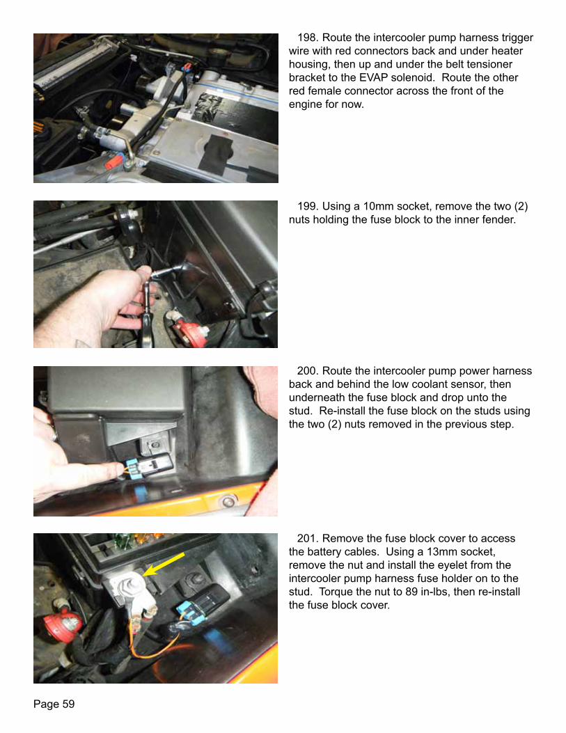
198. Route the intercooler pump harness trigger wire with red connectors back and under heater housing, then up and under the belt tensioner bracket to the EVAP solenoid. Route the other red female connector across the front of the engine for now.
199. Using a 10mm socket, remove the two (2) nuts holding the fuse block to the inner fender.
200. Route the intercooler pump power harness back and behind the low coolant sensor, then underneath the fuse block and drop unto the stud. Re-install the fuse block on the studs using the two (2) nuts removed in the previous step.
201. Remove the fuse block cover to access the battery cables. Using a 13mm socket, remove the nut and install the eyelet from the intercooler pump harness fuse holder on to the stud. Torque the nut to 89 in-lbs, then re-install the fuse block cover.

Page 60
202. Remove tape and small loom from MAF/IAT harness.
203. Remove the MAF wire further out of the loom.
204. Pull the MAF connector out to where the harness pokes out of the loom at the throttle body connector.
205. Tuck the remaining wiring back into the loom.

Page 61
206. Using higher quality electrical tape, close the loom back around the IAT wiring.
207. Using a quality sander or grinding disc, remove part of the center bolt on the back of the supercharger in order to make it flush with the machined surface.
208. Using blue Loctite® and a 5mm Allen socket, install the supercharger pulley using four (4) socket head cap screws.The pattern and torque specifications are shown in the following step. Use a strap wrench to hold the pulley still while tightening the screws.
209. This illustration shows the torque pattern for the supercharger pulley bolts. The bolts should be torqued to 8 ft-lbs.
1
23
4

Page 62
210. Using a Dremel or rotary tool, grind clearance in the supercharger for the button head bolts installed in steps 144-145. Mark the locations needed to drill by putting black ink on to the top of the button head bolts, then putting the supercharger on to the engine. This will leave black marks where the supercharger needs to be modified. NOTE: Depending on the supercharger build date, this step may be skipped. If your supercharger has this clearance, then this step is not needed.
211. Install the supplied intake port gaskets (PN: MS92438) into the supercharger base.
212. Using a pair of pliers, remove the two (2) center hood latch cable supports.
213. Position the E-Force supplied intercooler hose assembly along the firewall.

Page 63
214. Remove the tape covering the intake ports and spray a coating of silicone spray on the head surface.
215. With the help of an assistant, set the supercharger into place.
216. Using a 10mm swivel socket, ratchet, and extension, install the 8 (eight) 10mm intake manifold mounting bolts in the sequence shown. Torque these bolts to 4 ft-lbs (48 in-lbs) the first pass then to 7.5 ft-lbs (90 in-lbs) the second pass. Be sure to apply Loctite® Tight onto the bolts. NOTE: The red arrows show the locations of the button head bolts that where plugged in steps 144 and 145. There are no supercharger mounting bolts for these two (2) locations.
217. Connect the LPE-supplied MAP/IAT adaptor harness (PN: XX04468-0012) into the factory wiring harness.
Page 64
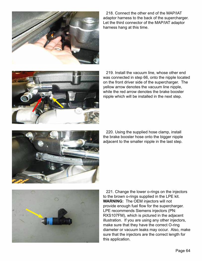
218. Connect the other end of the MAP/IAT adaptor harness to the back of the supercharger. Let the third connector of the MAP/IAT adaptor harness hang at this time.
219. Install the vacuum line, whose other end was connected in step 66, onto the nipple located on the front driver side of the supercharger. The yellow arrow denotes the vacuum line nipple, while the red arrow denotes the brake booster nipple which will be installed in the next step.
220. Using the supplied hose clamp, install the brake booster hose onto the bigger nipple adjacent to the smaller nipple in the last step.
221. Change the lower o-rings on the injectors to the brown o-rings supplied in the LPE kit. WARNING: The OEM injectors will not provide enough fuel flow for the supercharger. LPE recommends Siemens injectors (PN: RXS107FM), which is pictured in the adjacent illustration. If you are using any other injectors, make sure that they have the correct O-ring diameter or vacuum leaks may occur. Also, make sure that the injectors are the correct length for this application.

Page 65
222. Lubricate the o-rings and install the injectors into the supercharger. CAUTION: Take care not to cut or damage the o-rings when pushing the injectors into position.
223. Assemble the fuel rails as shown by the illustration.
224. Lubricate the upper o-rings on the driver-side injectors and slide the driver-side fuel rail on top of them. CAUTION: Take care not to cut or damage the o-rings when pushing the injectors into position, especially on the fuel side.
225. Push down while connecting the end of the crossover line. Install the safety clip. NOTE: Repeat steps 224-225 for the passenger-side fuel rail.

Page 66
226. Using blue Loctite® and a 5mm Allen socket, install the four (4) M8X12X6mm bolts that secure the fuel rail to the supercharger.
227. Route the injector harness down the sides of the supercharger, plugging the harness into the injectors while doing so.
228. Plug the factory EVAP connector into the jumper harness for the water pump.
229. Plug the supplied MAF sensor jumper harness into the harness connection. The jumper harness should be routed towards the driver side of the throttle body, making sure that it does not interfere with the belt routing. MAF Wiring Harness Extensions1997-2000 Corvette C5 XX04468-0013 2001-2004 Corvette C5 XX04468-0014

Page 67
230. Plug the throttle body extension harness (PN: CE105320) into the connector.
231. Route the modified IAT sensor harness across the supercharger and to the passenger side of the engine. Plug the IAT sensor into the adaptor harness.
232. Connect the throttle position sensor adaptor harness to the factory connector.
233. Route the throttle position sensor extension harness under the supercharger inlet and set aside with the other harnesses for now.

Page 68
234. Using a 3/16” Allen socket, remove the pipe plug from the side of the supercharger and save.
235. Apply Teflon Sealer on to the male fitting of the supplied stainless steel pipe “T” and install in to the supercharger.
236. Re-install the pipe plug removed in step 236 into the rear fitting of the pipe “T” NOTE: The rear fitting is where a nipple would be installed if a boost/vacuum gauge was to be installed.
237. With a 1-1/16 inch sender socket, install the pressure switch included in the Boost-A-Pump kit into the “T” fitting.

Page 69
238. Route the boost-a-pump pressure switch harness along the driver-side of the supercharger. Connect the harness to the pressure switch.
239. Connect the intercooler hose from the rear of the engine on to the backward-facing quick connect fittings on both sides of the supercharger.
240. Using a 10mm socket, install the coils and tighten the five (5) bolts. Plug in the harness connector. Repeat this step for the other side of the engine.
241. Install the spark plug wires.

Page 70
242. Install the supplied short EVAP hose with the 90 degree quick connect fitting on both ends. One end of the fitting will attach to the outside fitting of the EVAP solenoid. Route the hose under the tensioner bracket and connect to the fitting pointing down on the inlet housing.
243. Connect the supplied long hose with straight quick connect fittings on both ends. One end connects to the inside fitting of the EVAP solenoid. Route the hose under the supercharger and back to the fitting located on the driver-side of the firewall.
244. Install the supplied long hose with one straight connector. The connector goes on the fitting under the throttle body while the other end of the hose connects to the PCV valve located on the driver-side valve cover.
245. Using a 15mm socket and the factory bolts, re-install the alternator. Torque bolts to 35 ft-lbs.

Page 71
246. Re-install the positive charging wire on to the alternator. Using a 13mm socket, tighten the nut on to the battery cable stud. Torque the nut to 15 ft-lbs.
247. Install the loom onto the braided fuel line hose. Plug the hose into the U-shaped fitting on the driver-side fuel rail.
248. Install the factory safety clips onto both ends of the braided hose that connects to the fuel feed line. Make sure to secure the fuel line so that it is not in contact with anything that the fuel could react to.
249. Using the 16mm socket for the tensioner, install the supplied serpentine belt, following the adjacent routing illustration.
Page 72
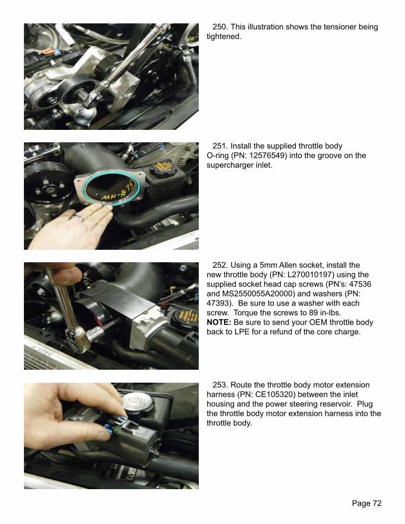
250. This illustration shows the tensioner being tightened.
251. Install the supplied throttle body O-ring (PN: 12576549) into the groove on the supercharger inlet.
252. Using a 5mm Allen socket, install the new throttle body (PN: L270010197) using the supplied socket head cap screws (PN’s: 47536 and MS2550055A20000) and washers (PN: 47393). Be sure to use a washer with each screw. Torque the screws to 89 in-lbs. NOTE: Be sure to send your OEM throttle body back to LPE for a refund of the core charge.
253. Route the throttle body motor extension harness (PN: CE105320) between the inlet housing and the power steering reservoir. Plug the throttle body motor extension harness into the throttle body.
Page 73
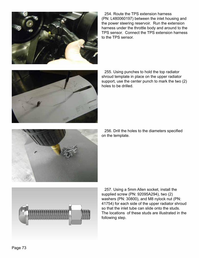
254. Route the TPS extension harness (PN: L480060197) between the inlet housing and the power steering reservoir. Run the extension harness under the throttle body and around to the TPS sensor. Connect the TPS extension harness to the TPS sensor.
255. Using punches to hold the top radiator shroud template in place on the upper radiator support, use the center punch to mark the two (2) holes to be drilled.
256. Drill the holes to the diameters specified on the template.
257. Using a 5mm Allen socket, install the supplied screw (PN: 92095A294), two (2) washers (PN: 30800), and M8 nylock nut (PN: 41754) for each side of the upper radiator shroud so that the inlet tube can slide onto the studs. The locations of these studs are illustrated in the following step.

Page 74
258. This illustration shows one of the studs in its inverted orientation so that the inlet tube can slide onto the stud.
259. Install the radiator support using the four factory bolts. Tighten with a 10mm socket.
260. Using a 3/32 inch Allen wrench and blue Loctite®, install and tighten the Edelbrock E-Force GM MAF sensor (PN: 15865791) with the supplied screws into the E-Force inlet tube.
261. Install the Edelbrock grommet and hose fitting on to the air inlet tube.

Page 75
262. Slip the LPE supplied hose (PN: XX04468-0022) onto the throttle body. The hose is taper cut, so make sure the flat side of the hose is on the throttle body with the shortest side up.
263. Install the air intake spacers (PN: XX04468-0002) over the studs on the radiator support.
264. Route the MAF wiring to the inside of the driver-side stud.
265. Install the air inlet tube onto the hose on the throttle body and slide down onto the studs.

Page 76
266. Install the E-force grommets. Using the LPE-supplied washers (PN: 30800) and M8 nuts (PN: 47385), snug the nuts until the spacers are no longer able to move easily.
267. Install the supplied black caps on top of the M8 nuts.
268. Using an 8mm socket, tighten the clamps on the inlet tube hose.
269. Connect the MAF sensor harness to the sensor on the inlet tube and secure the wiring by placing it in the holder.
Page 77
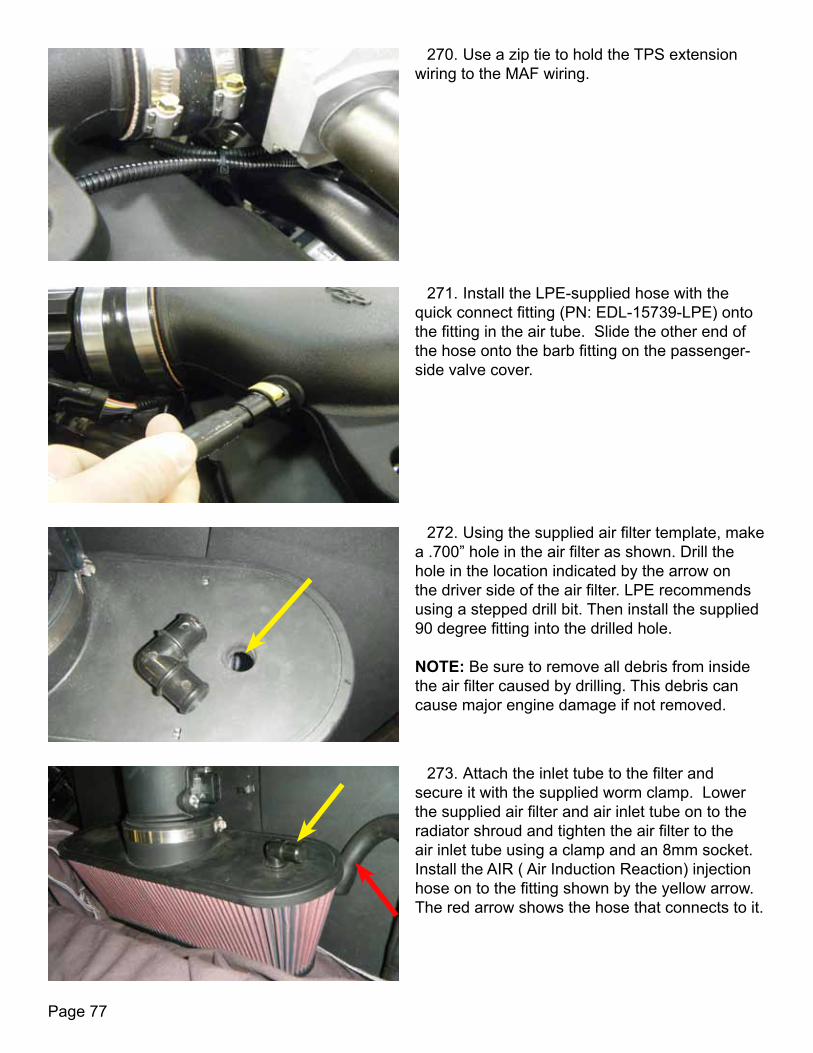
270. Use a zip tie to hold the TPS extension wiring to the MAF wiring.
271. Install the LPE-supplied hose with the quick connect fitting (PN: EDL-15739-LPE) onto the fitting in the air tube. Slide the other end of the hose onto the barb fitting on the passenger-side valve cover.
272. Using the supplied air filter template, make a .700” hole in the air filter as shown. Drill the hole in the location indicated by the arrow on the driver side of the air filter. LPE recommends using a stepped drill bit. Then install the supplied 90 degree fitting into the drilled hole. NOTE: Be sure to remove all debris from inside the air filter caused by drilling. This debris can cause major engine damage if not removed.
273. Attach the inlet tube to the filter and secure it with the supplied worm clamp. Lower the supplied air filter and air inlet tube on to the radiator shroud and tighten the air filter to the air inlet tube using a clamp and an 8mm socket. Install the AIR ( Air Induction Reaction) injection hose on to the fitting shown by the yellow arrow. The red arrow shows the hose that connects to it.
Page 78
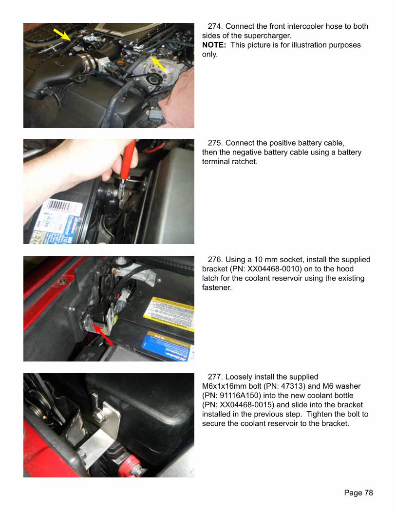
274. Connect the front intercooler hose to both sides of the supercharger. NOTE: This picture is for illustration purposes only.
275. Connect the positive battery cable, then the negative battery cable using a battery terminal ratchet.
276. Using a 10 mm socket, install the supplied bracket (PN: XX04468-0010) on to the hood latch for the coolant reservoir using the existing fastener.
277. Loosely install the supplied M6x1x16mm bolt (PN: 47313) and M6 washer (PN: 91116A150) into the new coolant bottle (PN: XX04468-0015) and slide into the bracket installed in the previous step. Tighten the bolt to secure the coolant reservoir to the bracket.

Page 79
278. Using the supplied clamp, connect rear intercooler hose to the top coolant bottle fitting.
279. Route the supplied hose from the bottom coolant bottle fitting to the pump inlet and secure to the bottom coolant fitting and the pump using the supplied clamps.
280. Plug in the horns and re-mount the horn bracket using a 13mm socket. Torque the bolt to 15 ft-lbs.
281. Using a 7mm socket, re-install the five (5) bolts that secure the horn cover into place. Torque the bolts to 45 in-lbs.
Page 80
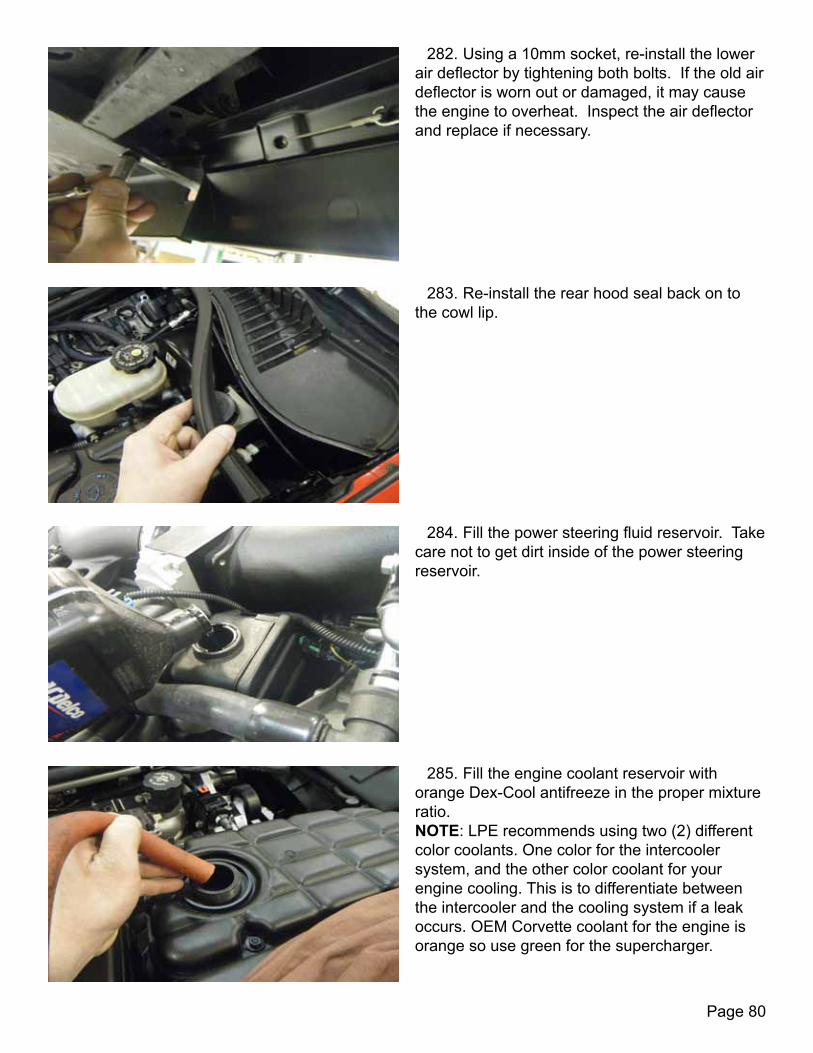
282. Using a 10mm socket, re-install the lower air deflector by tightening both bolts. If the old air deflector is worn out or damaged, it may cause the engine to overheat. Inspect the air deflector and replace if necessary.
283. Re-install the rear hood seal back on to the cowl lip.
284. Fill the power steering fluid reservoir. Take care not to get dirt inside of the power steering reservoir.
285. Fill the engine coolant reservoir with orange Dex-Cool antifreeze in the proper mixture ratio. NOTE: LPE recommends using two (2) different color coolants. One color for the intercooler system, and the other color coolant for your engine cooling. This is to differentiate between the intercooler and the cooling system if a leak occurs. OEM Corvette coolant for the engine is orange so use green for the supercharger.
Page 81
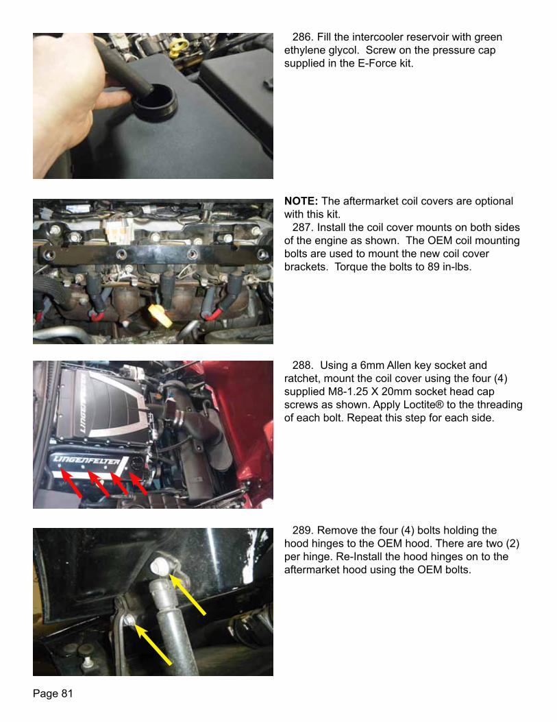
286. Fill the intercooler reservoir with green ethylene glycol. Screw on the pressure cap supplied in the E-Force kit.
NOTE: The aftermarket coil covers are optional with this kit.
287. Install the coil cover mounts on both sides of the engine as shown. The OEM coil mounting bolts are used to mount the new coil cover brackets. Torque the bolts to 89 in-lbs.
288. Using a 6mm Allen key socket and ratchet, mount the coil cover using the four (4) supplied M8-1.25 X 20mm socket head cap screws as shown. Apply Loctite® to the threading of each bolt. Repeat this step for each side.
289. Remove the four (4) bolts holding the hood hinges to the OEM hood. There are two (2) per hinge. Re-Install the hood hinges on to the aftermarket hood using the OEM bolts.

Page 82
290. If your new hood accepts the OEM hood light, transfer it over from the OEM hood to the new hood and install the aftermarket hood on to the vehicle.
291. This kit requires custom calibration. If the vehicle’s engine was completely stock prior to installing this kit, the correct calibration may be obtained through LPE. If there are any modifications to the vehicle in addition to the installation of this supercharger kit, custom calibration will be required. Take the vehicle to your local performance shop to have it calibrated correctly.
292. Turn the ignition key to the on position. Using the programmer, connect the connector into the OBDII connector on the vehicle located under the driver side dashboard. Upload the software to the vehicle through the programmer.
293. OPTIONAL STEP: Install the LPE diagnostic port cover kit (PN: L450110095) to protect the vehicle from being accidentally reprogrammed.

Page 83
Installation of the LPE C5 E-Force supercharger is complete. Refer to the supercharger break-in procedures below to prevent damaging the installed components.
294. Re-install the wheels and torque the lug nuts to 100 ft-lbs. The adjacent picture illustrates the proper torque sequence that should be used to torque the lug nuts on a 5-lug wheel.
1. Start the vehicle again and let run for 5-10 minutes. Check system fluid level and fuel leaks periodically. Check belt alignment. Shut off engine.
SUPERCHARGER BREAK-IN PROCEDURE
2. Test drive vehicle for the first few miles under normal driving conditions. Listen for any noises, vibrations, engine misfire or anything that does not seem normal. The supercharger does have a slight whining noise under boost conditions, which is normal.
Note: The supercharger requires a break-in period of 30 minutes of normal driving. Do not use wide open throttle until the break in period of the supercharger has been reached. 3. After the initial test drive gradually work the vehicle to wide open throttle runs, listen for any engine detonation (pinging). If engine detonation is present, let up on the throttle immediately. Most detonation causes are low octane gasoline still in the tank.
4. Once the break-in procedure has been performed, it is recommended that the engine oil is drained and the oil and filter are replaced with the vehicle’s recommended oil grade and filter.

Page 84
AB
7.5 A
AB
AB
0256 B4
Diagram 1

Page 85
0.440
0.9
00
R0.2
20
1.300
1.492
1.520
0.35
4 TH
RU0.
614
X 90
°X
9 PL
AC
ES
0.
354
THRU
R0.3
00 M
INIM
UMFL
AT S
URFA
CE
1.3
20
8.8
00
4.3
90 T
YP.
5.118
2.559
USE
BALL
NO
SED
END
MIL
L TO
MA
CHI
NE
0.17
5
AD
D R
AD
IUS
OR
CHA
M.
AD
D R
AD
IUS
OR
CHA
M.
ABZ
12/2
3/11
N/A
01:
1
N/A
N/A
C5
E-FO
RCE
VA
LLEY
TRA
Y M
OD
IFIC
ATIO
N
N/A
SCA
LE:
SIZE
DW
G.
NO
.
ARE
V.
MA
TERI
AL
FIN
ISH
DO
NO
T S
CA
LE D
RAW
ING
APP
LICA
TION
USED
ON
NEX
T A
SSY
DIM
ENSI
ON
S A
RE IN
INC
HES
TOLE
RAN
CES
:A
NG
ULA
R: M
AC
H 0
.5O
NE
PLA
CE
DEC
IMA
L
0.
2*TW
O P
LAC
E D
ECIM
AL
0.
01*
THRE
E PL
AC
E D
ECIM
AL
0.
005*
*UN
LESS
STA
TED
OTH
ERW
ISE
NA
ME
DA
TE
DRA
WN
CHE
CKE
D
ENG
APP
R.
MFG
APP
R.
Q.A
.
SHEE
T 1 O
F 1
WEI
GHT
:
CO
MM
ENTS
:
REVI
SIO
NS
DES
CRI
PTIO
NRE
V.D
ATE
APP
ROV
ED
THE
INFO
RMA
TION
CO
NTA
INED
IN T
HIS
DRA
WIN
G IS
THE
SO
LE P
ROPE
RTY
OF
LING
ENFE
LTER
PER
FORM
AC
E EN
GIN
EERI
NG
.A
NY
REPR
OD
UCTIO
N IN
PA
RT O
R A
S A
WHO
LEW
ITHO
UT T
HE W
RITT
EN P
ERM
ISSI
ON
OF
LING
ENFE
LTER
PER
FORM
AC
E EN
GIN
EERI
NG
IS P
ROHI
BITE
D.
PRO
PRIE
TARY
AN
D C
ON
FIDE
NTIA
L
DW
G. N
AM
E
NO
TES:
1. A
LL C
UTT
ING
DEP
THS
ARE
0.05
0"
Dia
gram
2
Page 86
Lingenfelter Performance Engineering1557 Winchester Road
Decatur, IN 46733(260) 724-2552
(260) 724-8761 faxwww.lingenfelter.com
L250280197 C5 E-Force Supercharger Installation Instructions v2.9indd
For additional product installation information and technical support, contact LPE or your LPE products distributor. You can also find technical support and usage discussions regarding this product and many other LPE products in our Internet forums:
http://www.lingenfelter.com/LPEforumfiles