c210_wml_611
DESCRIPTION
Manual Ssangyong korandoTRANSCRIPT

11-34890-00
1. SPECIFICATION
Unit DescriptionSpecification
ABS ESP
HECU Clock frequency 32 MHz 50 MHz
Memory 128 KB 512 KB
Switch Orifice Orifice
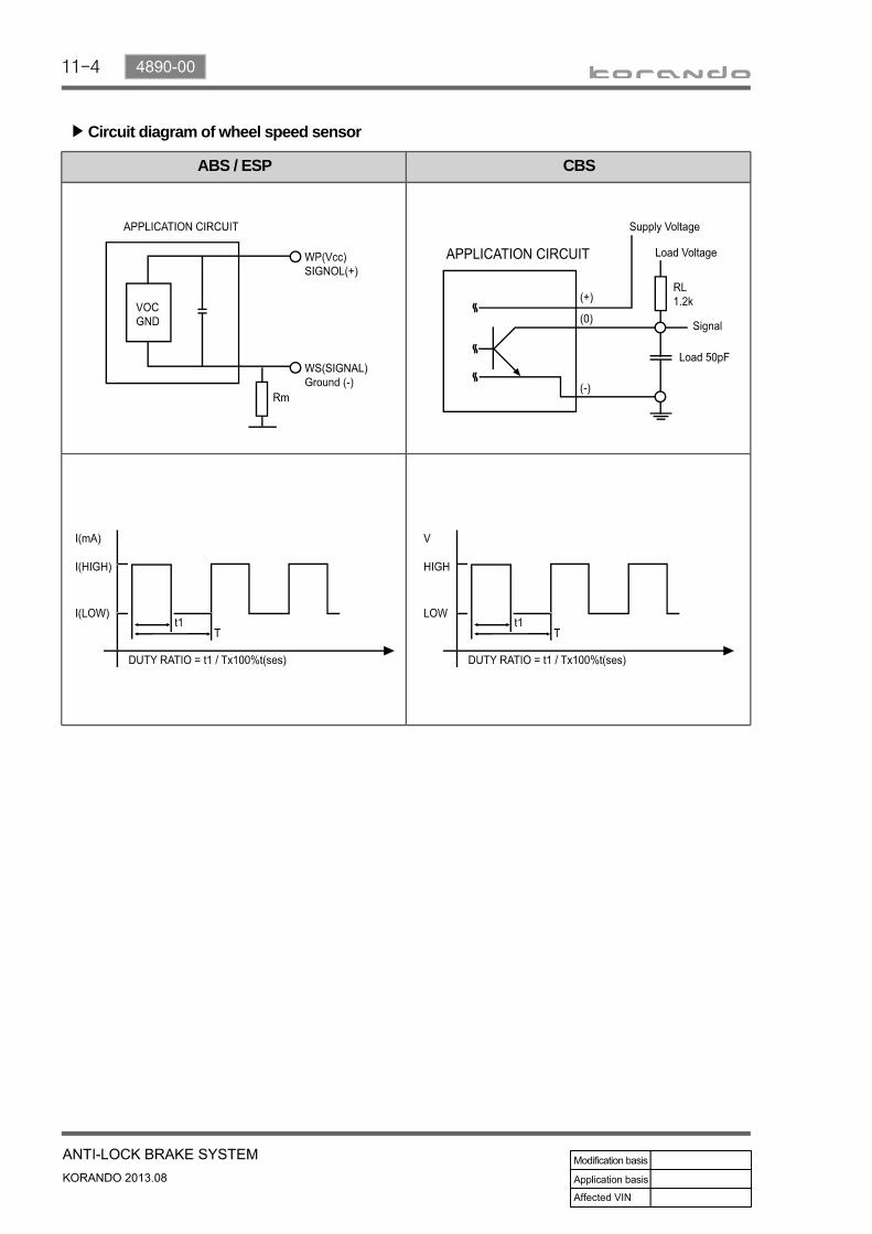
Wheel speed sensor
ABS / ESP CBS
Operating temperature - 40°C to 150°C - 40°C to 150°C
- 40°C to 115°C - 40°C to 115°C
Operating frequency 1 to 2,500 Hz 1 to 8,000 Hz
Operating voltage 4.5 to 16 V 3.3 to 18 V
G-sensor ABS CBS / ESP
Operating voltage 4.75 to 5.25 V N/A
Operating temperature - 30°C to 85°C
Operating range -1.5 to 1.5 g
Output voltage 0.5 to 4.5 V
11-4
ABS / ESP CBS
Circuit diagram of wheel speed sensor▶

11-54890-00
1. SYSTEM OVERVIEW1) What is ABS?When braking suddenly or braking on slippery roads, the vehicle keeps moving forward but the wheels are locking and not rotating. If these happen, the vehicle may lose stability or rotate resulting in an accident. ABS helps to maintain directional stability and control of the vehicle. ABS is designed to secure more safety and increase the control of steering wheel during emergency braking situation. But, ABS does not guarantee perfect safety beyond its physical limit. ABS in this vehicle contains EBD function. In normal driving conditions, the brake system operates without ABS function.
2) What is EBD (Electronic Brake-force Distribution)?EBD is an automobile brake technology that automatically varies the amount of force applied to each of a vehicle's brakes, based on road conditions, speed, loading, etc. Always coupled with anti-lock braking systems, EBD can apply more or less braking pressure to each wheel in order to maximize stopping power whilst maintaining vehicular control. EBD does not operate when ABS is working.
ABS effect according to braking conditions▶
Braking on split road Maneuvering while braking

11-6
3. G-sensor (for 4WD)
Located on the floor under parking brake bracket in center console.
4. Rear wheel speed sensor (for 2WD)
Located on knuckle. The appearance is different from that for 4WD.
4. Wheel speed sensor(for 4WD)
Located on knuckle. The appearance of front sensor is same with rear sensor.
2. ABS warning lamp
EBD warning lamp (ABS warning lamp + Brake warning lamp)
1. ABS hydraulic device and control unit
Located under the power steering fluid reservoir and contains the pressure sensor.
2. COMPONENT

11-74890-00
4WD - Front/Rear wheel speed sensor
2WD - Front wheel speed sensor
2WD - Rear wheel speed sensor
ECU (Electronic Control Unit)1.
ECU calculates the wheel speed, acceleration and deceleration with the information from wheel speed sensor, and determines the wheel slip to control the valve and motor.
HU (Hydraulic Unit)2.
The hydraulic circuit contains the primary circuit and secondary circuit for ABS operation. This unit controls the hydraulic pressure to each wheel. If the system needs ABS operation, the valves in the unit operate to control HOLD, RISE and DUMP according to ECU control logic.
Motor3.
The motor is operated when ABS is activated. The cam-shaped output shaft of the motor enables the brake system to receive and supply the brake fluid during the motor operation.
Wheel speed sensor▶
Wheel speed sensor sends the data detected by tone wheel to HECU.
HECU▶
Rear wheel speed sensor in 2WD vehicle is different from that in 4WD vehicle.
Location of rear tone wheel (A) and wheel sensor (B) in 2WD vehicle

11-8
G-sensor (only for 4WD)▶
For the vehicle with the ABS, a speed difference between the wheels is not noticeable as all the wheels are slipping during abrupt braking. Therefore, the vehicle needs the speed information from other sensors other than the wheel speed sensor. On the 2WD vehicle, there is not large difference between the vehicle speed reduction and actual wheel speed reduction in the event of braking since the driving wheels are in the front. So, the ABS HECU can control the vehicle, based on a calculation value. But, on the 4WD vehicle, if a speed reduction occurs in the front or rear of the vehicle, it affects the other side wheel. In other words, braking the rear wheels induces also a large speed reduction in the front wheels. The longitudinal acceleration sensor is used for this case. It controls the ABS by using the signals from the sensor during abrupt braking and acceleration.
G-sensor

11-94890-00
3. ABS CONTROL LOGIC
The principal ABS control logic is the determination of the reference speed by choosing one wheel meeting a certain condition, while sensing the speed information from 4 wheel speed sensors when the vehicle is being driven.For example, when the comparison of the reference speed with front right wheel speed shows a slip, the control signal is determined according to whether it's deceleration or acceleration. If the control conditions are met, the brake for the front right wheel will be got under control.

11-10
4. WARNING LAMPS
1) ABS Warning LampABS warning lamp module indicates the self diagnosis and malfunction.ABS warning lamp ON:
When turning the ignition switch to ON position, ABS warning lamp comes on for 3 seconds for self-diagnosis and goes off if the system is OK (initialization mode).When the system is defective, the warning lamp comes on.When the self-diagnosis is performing, the warning lamp comes on.When the HECU connector is disconnected, the warning lamp comes on.ABS is not available during lamp ON. In this condition, Only normal brake system without ABS function is available.When the communication between warning lamp CAN module in meter cluster, the warning lamp comes on.
1.
2.3.4.5.
6.
ABS warning lampBrake warning lamp(EBD warning lamp: ABS warning lamp + Brake warning lamp)
1.2.

11-114890-00
2) EBD (Electronic Brake-force Distribution) Warning Lamp (Brake Warning Lamp)EBD warning lamp when the system performs the self diagnosis and when it detects the malfunction of EBD system. However, the brake warning lamp comes on regardless of EBD when the parking brake is applied.EBD warning lamp ON:
When turning the ignition switch to ON position, ABS warning lamp and the brake warning lamp comes on for 3 seconds for self diagnosis and goes off if the system is OK (initialization mode).When applying the parking brake, the brake warning lamp comes on.When the brake fluid is not sufficient, the brake warning lamp comes on.When the self-diagnosis is performing, the warning lamp comes on.When the HECU connector is disconnected, the warning lamp comes on.When the system is defective, ABS warning lamp and the brake warning lamp come on simultaneously.
1.
2.3.4.5.6.
When the solenoid valve is defectiveWhen one or more wheel sensors are defectiveWhen ABS HECU is defectiveWhen the voltage is abnormalWhen valve relay is defective
a.b.c.d.e.
When the communication between warning lamp CAN module in meter cluster, the warning lamp comes on.
7.

11-12
5. SYSTEM OPERATION1) Block Diagram of ABS HECU

11-134890-00
2) Basic Theory of ABS FunctionTo give you a better understanding of the tasks and functions of ABS, we will first look at the physics principles.
(1) Stopping distanceThe stopping distance depends on the vehicle weight and initial speed when braking starts. This also applies for vehicle with ABS, where ABS always tries to set an optimum brake force on each wheel. As great forces are exerted between the tires and the carriageway when braking, even with ABS the wheels may scream and rubber is left on the road. With an ABS skid mark one may be able to clearly recognize the tire profile. The skid mark of an ABS vehicle does not however leave any hint of the speed of the vehicle in the case of an accident, as it can only be clearly drawn at the start of braking.
(2) Brake force on a wheelThe maximum possible brake force on a wheel depends on the wheel load and the adhesion coefficient between tire and carriageway. With a low adhesion coefficient the brake force, which can be obtained is very low. You are bound to know the result already from driving on winter roads. With a high adhesion coefficient on a dry road, the brake force, which can be obtained, is considerably higher. The brake force, which can be obtained, can be calculated from below formula:
Maximum brake force▶
FBmax = wheel load FR x coefficient of frictionMh
The braking process cannot be described sufficiently accurately with the brake forces calculated. The values calculated only apply if the wheel is not locked. In the case of a locking wheel, the static friction turns into lower sliding friction, with the result that the stopping distance is increased. This loss of friction is termed "slip" in specialist literature.

11-14
Slip ▶
The brake slip is the difference between the vehicle speed and the wheel circumference speed. If the wheel locks, the slip is greatest, that is 100 %. If the wheel is running freely and un-braked, the slip is the lowest, equal to 0 %. Slip can be calculated from the vehicle speed Vveh and the wheel speed Vw. The equation for this is:
Vveh = 100 km/h, Vw = 70 km/h
Slip ratio (S) =
For the various road conditions, the friction coefficients were plotted. The typical course of the curves is always the same. The only special feature is shown by the curve for freshly fallen snow, for this curve increases at 100 % slip. In a vehicle without ABS, the wheel locks on braking and therefore pushes a wedge before it. This wedge of loose surface or freshly fallen snow means and increased resistance and as a result the stopping distance is shorter. This reduction in stopping distance is not possible with a vehicle with ABS, as the wheel does not lock. On these surfaces the stopping distance with ABS is longer than without ABS. The reason for this is based in physics and not in the Anti-Lock System. However, as mentioned before, ABS is not about the stopping distance, but maneuverability and driving stability, for the vehicle with locking wheels without ABS cannot be steered.
Typical Slip Curves▶
Vveh - Vw
VvehX 100%
S = 30%

11-154890-00
KAMM circle▶
Before we go into the Kamm circle, you should know that a tire offers a maximum of 100 % transmissibility. It is all the same for the tire whether we require 100 % in the direction of braking or in the direction of the acting lateral force, e.g. when driving round curves. If we drive into a curve too fast and the tire requires 100 % transmissibility as cornering force, the tire cannot transmit any additional brake force. In spite of the ABS the car is carried out of the curve. The relationship between brake force B and cornering force S is shown very clearly in the Kamm circle. If we put a vehicle wheel in this circle, the relationship becomes even clearer. In this relationship: as long as the acting forces and the resulting force remain within the circle, the vehicle is stable to drive. If a force exceeds the circle, the vehicle leaves the road.
Brake forceWhen depressing the brake pedal the brake force increases to the maximum, then the brake force decreases until the wheel locks.Cornering forceThe cornering force is a maximum when the wheel is turning freely with zero slip. When braking the cornering force falls to zero if the wheel locks (slip 100 %).ABS operating rangeThe operating range starts just before the maximum brake force and ends in maximum, for the unstable range then begins, in which no further modulation is possible. The ABS controls the regulation of the brake pressure so that the brake force only becomes great enough for a sufficient proportion of cornering force to remain. With ABS we remain in the Kamm circle as long as the car is driving sensibly. We will leave driving physics with these statements and turn to the braking systems with and without ABS.
-
-
-
Brake and cornering force▶

11-16
3) Basic ABS ControlOperation of ABS control unit▶
Applications of the ABS control unit The signals produced by the wheel sensors are evaluated in the electronic control unit. From the information received, the control unit must first compute the following variables:
Wheel speedReference speedDecelerationSlip
----
Reference speed▶
The reference speed is the mean, I.e. average speed of all wheel speeds determined by simple approximation.
Simplified ABS control▶
If, during braking, one wheel speed deviates from the reference speed, the ABS control unit attempts to correct that wheel speed by modulating the brake pressure until it again matches the reference speed. When all four wheels tend to lock, all four wheels speeds suddenly deviate from the previously determined reference speed. In that case, the control cycle is initiated again in order to again correct the wheel speed by modulating the brake pressure.

11-174890-00
4) ABS Control Pattern
The ABS control is performed by comparing the reference speed with each wheel speed. Firstly, it is determined whether the vehicle is in the deceleration or acceleration state using the wheel speed change ratio. Then, a signal is transmitted to the valve.Finally, the brake pressure is adjusted via the signal.

11-18
5) EBD (Electronic Brake Force Distribution) System System description▶
As an add-on logic to the ABS base algorithm, EBD works in a range in which the intervention thresholds for ABS control are not reached yet.EBD ensures that the rear wheels are sensitively monitored for slip with respect to the front axle. If slip is detected, the inlet valves for the rear wheels are switched to pressure hold to prevent a further increase in pressure at the rear-wheel breaks, thus electronically reproducinga pressure-reduction function at the rear-wheel brakes.ABS features an enhanced algorithm which includes control of the brake force distribution between the front and rear axles. This is called Electronic Brake Distribution. In an unloading car condition the brake efficiency is comparable to the conventional system but for a fully loaded vehicle the efficiency of the EBD system is higher due to the better use of rear axle braking capability.
Advantages▶
Elimination of conventional proportioning valve EBD utilizes the existing rear axle wheel speed sensor to monitor rear wheel slip.Based on many variables in algorithm a pressure hold, increase and/or decrease pulsetrain may be triggered at the rear wheels insuring vehicle stability.Vehicle approaches the ideal brake force distribution (front to rear).Constant brake force distribution during vehicle lifetime.EBD function is monitored via ABS safety logic (conventional proportioning valves are not monitorable).
-
-
-
-
-

11-194890-00
6. HYDRAULIC CIRCUIT OF ABS1) Normal Brake Operation (ABS is not working) ModeIf the driver depress the brake pedal so that the ABS does not operate, the hydraulic pressure in the master cylinder increases through the vacuum booster and it is delivered to the wheel via the normal open inlet valve. At this moment, the normally-closed outlet valve is closed The speed of the wheel that hydraulic pressure is delivered reduces gradually.
Solenoid valve Valve Open/Close Pump motor
Inlet valve - Normal open (NO) valve OpenOFF
Outlet valve - Normal close (NC) valve Close

11-20
2) DUMP (ABS is working) ModeEven when the hydraulic pressure on each circuit is constant, the wheel can be locked as the wheel speed decreases. This is when the ABS HECU detects the wheel speed and the vehicle speed and gives the optimized braking without locking the wheels. In order to prevent the hydraulic pressure from increasing, the inlet valve will be closed, the outlet valve will be opened and the oil will flow into the low pressure chamber. In addition, the ABS HECU operates the pump to circulate the oil in the low pressure chamber to the master cylinder. This may make the driver to feel the brake pedal vibration and some noises.
Solenoid valve Valve Open/Close Pump motor
Inlet valve - Normal open (NO) valve CloseON
Outlet valve - Normal close (NC) valve Open

11-214890-00
3) HOLD (ABS is working) ModeAs hydraulic pressure on each wheel increases, the wheel tends to lock. In order to prevent the wheel from locking, the hydraulic valve modulator operates the inlet valve control solenoid to stop increasing the hydraulic pressure by closing the inlet valve. At this moment, the outlet valve is closed. This procedure helps the wheel to maintain a constant hydraulic pressure.
Solenoid valve Valve Open/Close Pump motor
Inlet valve - Normal open (NO) valve CloseOFF
Outlet valve - Normal close (NC) valve Close

11-22
4) RISE (ABS is working) ModeAs the wheel speed increases, the inlet valve opens and the wheel's pressure increases due to the master cylinder pressure. In addition, the pump circulates the oil in the low pressure chamber to the wheel. As the hydraulic pressure to the wheel increases, the wheel speed will reduce. This operation continues repetitively until there are no signs that the ABS HECU tends to lock the wheels. Since the ABS hydraulic pressure control process takes place repeatedly for a short time, there may be some vibration and noises at the brake pedal.
Solenoid valve Valve Open/Close Pump motor
Inlet valve - Normal open (NO) valve OpenON
Outlet valve - Normal close (NC) valve Close

11-234890-00
7. CIRCUIT DIAGRAM