c210_wml_209
DESCRIPTION
Manual Ssangyong korandoTRANSCRIPT

09-30000-00
1. SPECIFICATIONSpecification HPS EPS
Alternator Crankshaft pulley : Alternator Pulley 1 : 2.94
Normal output (idling/2200 rpm) 70/120 A 70/140A
Regulator voltage 14.6 V ←
Brush Length 12.5 mm ←
Wear limit 7 mm ←
Battery Type MF ←
Capacity 90AH ←

09-4
2. INSPECTION1) Alternator Output Test
Item How to check DTC set value / Action
Output current
B terminal current
Rotor coil
resistance
L terminal voltage
Disconnect the cable connected to the B terminal on the alternator. Connect one end of the ammeter to the B terminal and the other end to the cable connected to the B terminal. Measure the maximum output value. (Maintain the engine speed between 2,500 and 3,000 rpm.) (Turn the headlamp and all the electrical switches on.)
1.
2.
Pass: If the measured current is 45 A or higher. Fail: If the measured current is less than 45 A.Check the current of the B terminal.
-
-
-
Move the gear selector lever to the neutral position.Maintain the engine speed at 2,500 rpm with the vehicle unloaded.(Turn all the electrical switches off.)
1.
2.
Open circuit: If the measured current is 5 A or higher.
-
Disconnect the negative cable from the battery. Remove the B terminal and turn off the ignition switch. Measure the resistance between the L and F terminals with an ohmmeter.
1.
2.
3.
Pass: If the measured resistance is between 3 and 6 Ω.
Faulty rotor coil or slip ring: If the measured resistance is less than 3 Ω or greater than 6 Ω.
-
-
Connect the B terminal wiring.Measure the voltage with the engine running.
1.2.
Specification: 12.5 V to 14.5 VFaulty IC regulator or field coil: If the measured voltage is 14.5 V or higher.
--
Disconnect the negative battery cable.Connect the negative cable again after connecting the ammeter.
--

09-50000-00
2) Troubleshooting for Alternator
Item Cause Action
Overcharged battery Defective alternator voltage regulator Replace
defective alternator detection wiring Repair or replace
Discharged battery Loose alternator drive belt Adjust the belt tension or replace
Poor connection of related circuit or open circuit
Retighten the loose connection or repair open circuit
Defective alternator voltage regulator Replace
Terminated battery Replace
Defective ground Repair
Charge warning lamp does not come on when turning on ignition switch
with engine stopped
Defective alternator voltage regulator Replace
Open circuit in charge warning lamp, fuse or wiring
Replace or repair the charge warning lamp or fuse
Defective ignition switch Replace
Defective ground of alternator circuit Repair
Charge warning lamp does not go off after
starting engine
Defective alternator voltage regulator Replace
Corroded or worn battery cable Repair or replace
Loose alternator drive belt Adjust the belt tension or replace the belt
Defective wiring harness Repair or replace

09-6
3) Checking Battery

09-70000-00
(1) CheckingUsing battery tester
PASS (11.0 V or more): Explain to the customer that the battery is reusable.Need to be charged (9.0 to 11.0 V): Charge the battery with a charger and reinstall it. Explain it to the customer.Need to be replaced (9.0 V or more): The battery should be replaced due to overdischarging.
--
-
(2) How to use battery tester
How it works and How to use it
Determine battery capacity by fixing current (load capacity) and time and varying voltage.Determine battery capacity based on the amount of voltage drop when discharging a fixed load capacity (120 A) for 5 seconds.Connect the tester to the battery and read the display while applying a load for 5 seconds.
-
-
-
How to read display
Red area (①): overdischarge or faulty
batteryYellow area (②): Need to be charged
(using a vehicle alternator and a battery charger)Green area (③): Normal
Red area on the left-hand side of OK (④): Impossible to charge with an
alternatorGreen area with OK (⑤): Normally
chargedRed area on the right-hand side of OK (⑥
Overcharged by an alternator
-
-
--
-
-

09-8
(3) Starting with jumper cable
If the battery is weak or terminated, the battery from another vehicle can be used with jumper cables to start the engine.
Connecting order
The positive (+) terminal of the discharged batteryThe positive (+) terminal of the booster batteryThe negative (-) terminal of the booster batteryConnect one end of the other jumper cable to the body of the discharged vehicle, such as the engine block or a front towing hook.
1.2.3.4.
Starting
Prepare a set of jumper cables.Place another vehicle that has the same 12 V of power near to the discharged vehicle.Switch off all electrical accessories for the discharged vehicle.Apply the parking brake and shift the transaxle to the P position (automatic transaxle) or neutral (N) position (manual transaxle).Connect the jumper cables.Try to start the discharged vehicle while accelerating the engine rpm in the booster vehicle.Attempt to start the engine with the discharged battery.After starting the engine, carefully disconnect the jumper cables in the reverse sequence of connection.
1.2.3.4.
5.6.7.8.

09-90000-00
(4) Maintenance
Make sure that the battery cables are firmly connected.If the terminals are corroded, clean them with a wire brush or sandpapers.Always disconnect the battery cables with the ignition key removed. When disconnecting the battery cables with the ignition key turned to ON or ACC position, several electric units can be damaged due to sudden voltage change.Check the battery for crack, damage or fluid leaks. Replace it if necessary. Wipe out the battery fluid on the battery surface using a rubber glove and a clean cloth wetted with soapy water.
---
- -
If the charge warning lamp ( ) on the instrument cluster comes on while driving, there is a malfunction in the charge system including the battery. Therefore, carrying out the system check is needed.
09-10
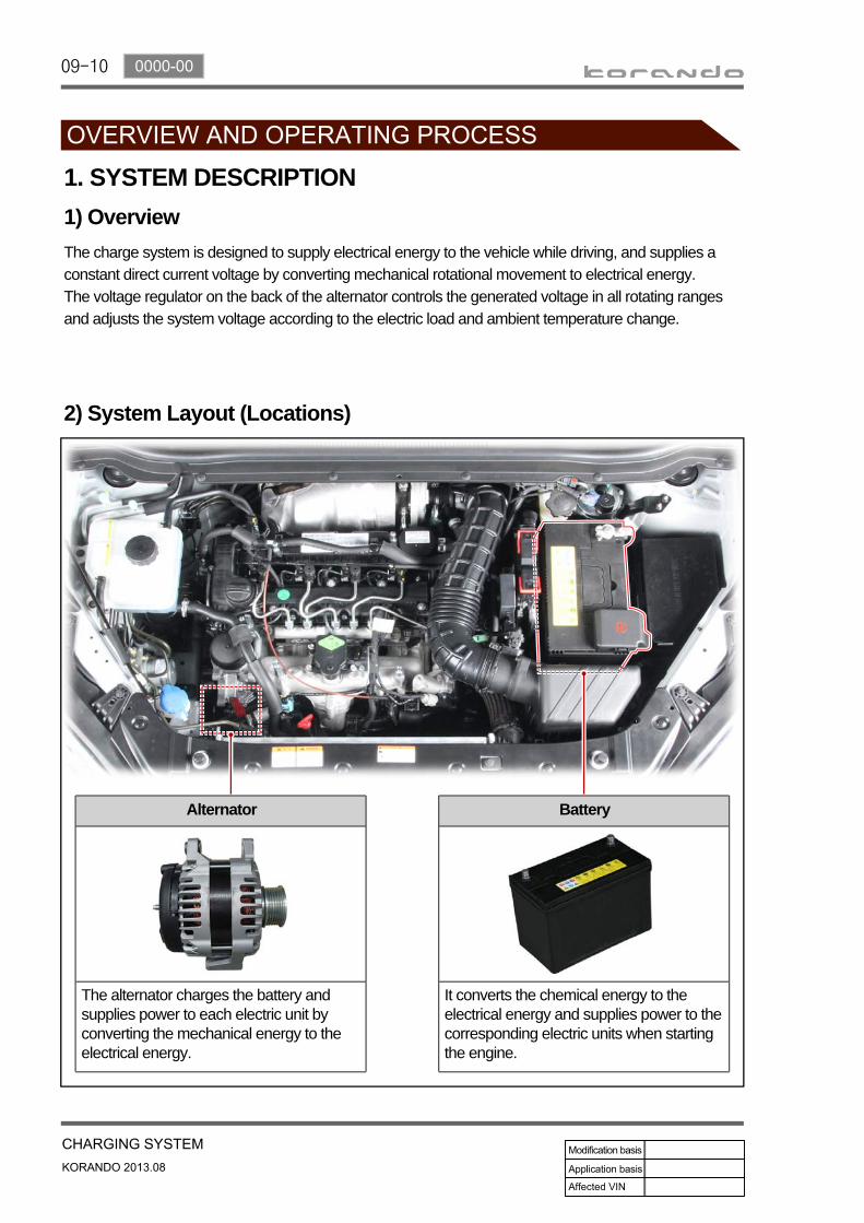
Battery
It converts the chemical energy to the electrical energy and supplies power to the corresponding electric units when starting the engine.
Alternator
The alternator charges the battery and supplies power to each electric unit by converting the mechanical energy to the electrical energy.
1. SYSTEM DESCRIPTION1) OverviewThe charge system is designed to supply electrical energy to the vehicle while driving, and supplies a constant direct current voltage by converting mechanical rotational movement to electrical energy.The voltage regulator on the back of the alternator controls the generated voltage in all rotating ranges and adjusts the system voltage according to the electric load and ambient temperature change.
2) System Layout (Locations)

09-110000-00
Alternator (140 A)Alternator (120 A)
3) ChargingThe alternator uses a new regulator which has three diodes. It consists of the delta stator, rectifier bridge, slip ring and brush.
Charging time according to vehicle conditions and environment
Specification: Charging a fully depleted high-capacity battery takes twice or more as long as charging a fully depleted battery for small vehicles.Temperature: The lower the temperature is, the longer the time taken to charge the battery. When connecting the battery charger to the cold battery, the amount of current the battery can accept initially is very small. As the battery gets warmer, it can accept more current.
Charging capacity: Charging a battery with a low-capacity charger takes longer time than charging with a high-capacity charger.Charging status: Charging a fully depleted battery takes twice or more as long as charging a half-depleted battery. Since the electrolyte in a fully depleted battery consists of nearly pure water and conductor, only a very small amount of current can be accepted by the battery initially. The charging current increases as the amount of acids in the electrolyte is increased by the charging current.
4) Output Characteristics
09-12
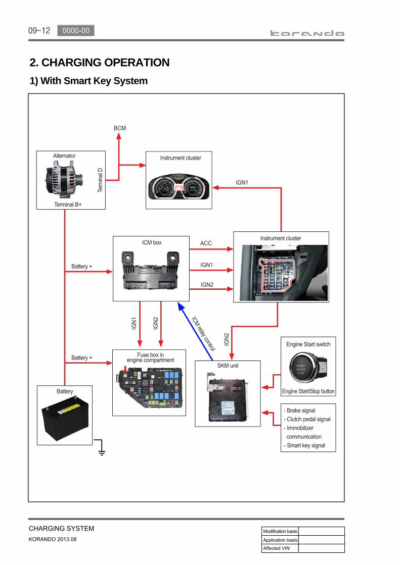
2. CHARGING OPERATION1) With Smart Key System

09-130000-00
2) Without SMART Key System

09-14
3. CIRCUIT DIAGRAM

09-150000-00