c0 ,'4 dtrc/shd-1268-03 dec m8 departmental report ... · c0,'4 dtrc/shd-1268-03 dec m8...
TRANSCRIPT

/ -I1 fILE GOP)David Taylor Research CenterBethesda, MD 20084-5000
0
c0
,'4
DTRC/SHD-1268-03 DEC m8SHIP HYDROECHANICS DEPARTMENT
DEPARTMENTAL REPORT
CD
0 ANALYSIS OF PROPELLER WAKE FLOW VISULAILZATIONNINAR A FREE SURFACE
By
Scott FishJames N. Blanton
0
C" APPROVED FOR PUBLIC RELEASE
DISTRIBUTION UNLIMITED
DTICA a ELE TEo 1 9 JAN 1989
STED89 1 18 092

CODE 011 DIRECTOR OF TECHNOLOGY, PLANS AND ASSESSMENT
12 SHIP SYSTEMS INTEGRATION DEPAATMENT
14 SHIP ELECTROMAGNETIC SIGNATURES DEPARTMENT
15 SHIP HYDROMECHANICS DEPARTMENT
16 AVIATION DEPARTMENT
17 SHIP STRUCTURES AND PROTECTION DEPARTMENT
18 COMPUTATION, MATHEMATICS & LOGISTICS DEPARTMENT
19 SHIP ACOUSTICS DEPARTMENT
27 PROPULSION AND AUXILIARY SYSTEMS DEPARTMENT
28 SHIP MATERIALS ENGINEERING DEPARTMENT
This document contains information affecting the national defense of the United Stateswithin the meaning of the Espionage Laws, Title 18, U.S.C., Sections 793 and 794. Thetransmission or revelation of its contents in any manner to an unauthorized person isprohibited by law.
DTRC ISSUES THREE TYPES OF REPORTS:
1. DTRC reports, a formal series, contain information of permanent technical value.They carry a consecutive numerical identification regardless of their classification or theoriginating department.
2. Departmental reports, a semiformal series, contain information of a preliminary,temporary, or proprietary nature or of limited interest or significance. They carry adepartmental alphanumerical identification.
3. Technical memoranda, an informal series, contain technical documentation oflimited use and interest. They are primarily working papers intended for internal use. Theycarry an identifying number which indicates their type and the numerical code of theoriginating department. Any distribution outside OTRC must be approved by the head ofthe originating department on a case-by-case basis.

UNCLASSIFIEDsjCU~rIY CLASSIFICArION OF T1415 PAtit
REPORT DOCUMENTATION PAGEIa. REPORT SECURITY CLASSIFICATION lb. RESTRICTIVE MARKiNGS
UNCLASSIFIED2a. SECURITY CLASSIICATION 'AUTH4ORITY I DISTRI*UYIONIAVAILAIUTY OF REPRT
2b. DECLASSIFICATION1I OWNGRADING SCHEDULE STATEMENT A
4. PERFORMING ORGANZATION REPORT NUMBER(S) S. MONITORING ORGANIZATION REPORT NUMBER(S)
DTRCISED-1268-O3
da. NAME OF PERFORMING ORGANIZATION 6b OFFICE SYMBOL Ia. NAME OF MONITORING ORGANIZATION
fic. ADDRESS (City. State. and ZIP Cod) 1b. ADDRESS (City. State. and 2W Code)Bethesda, MD, 2Q084-500ft
Ba. NAME OF FUNDING / SPONSORING Sb. OFFICE SYMBOL 9. PROCUREMENT INSTRUMENT IDENTIFICATION NUMBER
Office of Naval Research _____________________
Sc. ADORE SS (CitY. Stat. and ZIP Code) 10 SOURCE OF FUNDING NUMBERSPORM POECT ITASK ~ WORK UNIT
Alexandria, VA 22217 ELEMENT NO, INO.- N'2O l JACS NO061U53N P03.N DN50716
11 TITLE (Inclutde SOCUfftY C4016S00fc~~n)
Analysis of Propeller Wake Flow Visualization Near a Free Surface
12 PFRSONAL AUrHOR(S)Scott Fish, James No Blanton
13a. TYPE OF REPORT 113b TIME COVERED 14 DATE Of REPORT (roar, Montbh. Day) jS. PAGE COUNTTechnical IFROM .L8... To _qLaa_. I 1Q88 No'vrmhpr I
16 SUPPLEMENTARY NOTATION
I? COSATI CODES 1S SUBJECT TERMS (Contunu an revert af necenary and idmntsl v by block number)
FIEL ! I GROU SU .GRO P ( ortex i flne ja 5 * s F low/ sualization . C jc )' 4
13 4ISTRACT (Continu On revrte if neCeSSary and idsnt\fy by block number)--.,Propeller wake flow visualization 'was carried out f or several dep ths of submergence
below a free surface. The wake was visualized by laser light sheet illumination of theblade tip vortex helix seeded with. fluorescein dye. Effects of the free surface on thepropeller wake were seen at the shallower submergence depths. Instability in the helix was.2pparent at much shorter distances downstream than has previously been observed in cavita-tion experiments. The dominant cause of this" instability is determined to be caused by theuse of inclined universal joints in the propeller drive system. A simple test modificationis described for the elliination of this influenace. Estimation of Reynolds number, sub-mergence depth, and propeller loading influences on the propeller wake are given.
~i~~)rA5.~A~iie~ ro .eZ- sv , .i(,
20 DISTRISUTIONIAVALAtiUTY OF ASRACT 21. ABSTRACT SECURITY CLASSIFICATIONO UPCLASSIE1DONLIMITEO 13 SAME AS RPT (3 OTIC USERS NLqTTn
12a NAEO2EPOSBE2DIIULZb TELEPHONE W(MCAena CbW) 22c. OFFICE SYMBOL
00 FORM 1473.asa MA 63 APIR editio ny be v~ %M exase SECURITY cLAssiFcAtION OF TIS PAGEANl @1w editmftii are ObiWOlt
k_ UNCLASSIFIED
CONTENTS
NOTATION ............................................... vSAESTRACTT 1
INTRODUCTION ............................................ IEXPERIMENTAL ARRANGEMENT ............................... 2
DYE INJECTION FLOW VISUALIZATION .......................... 4
WAKE HELIX INSTABILITY ................................... 5
PRESENTATION OF RESULTS .................................. 9REYNOLDS NUMBER DEPENDENCE ......................... 9PROPELLER LOADING VARIATION ......................... 10PROPELLER DEPTH VARIATION ........................... 13
EWa e Inlm c .............................. 13Free S f Inflence................................. 14
WAKE PERSISTENCE ...................................... 16
DISCUSSION AND RECOMMENDATIONS ............................ 17
REFERENCES ............................................. 31
Aeeession For
NTIS GRA&IDTIC TABUnannounced "
JustificatioBy,______________
Distribution/ oOm
Availability CodesI I- 7zi7Dist Special
4A:-/L
M__i

FIGURES
Fig. 1. Four bladed propeller with hollow hub and dye slotted blades ...... 19Fig. 2. Experimental configuration . ................ 20Fig. 3. Laser light sheet and video camera configuration . ......... 21Fig. 4. Video frames of vortex twisting, 1=0.5, 0.1 second increments.............22Fig. 5. Angular position of motor drive "hf and propeller................... 23
Fig 6.Theediesoa vew of tip vortex helix........................ 24Fig. 7. Wake video frames for different RejL............................ 25Fig. 8. Wake video frames: J variation, 7..AJ=2.0............... 27Fig. 9. Calculated blade loading and vortex spacing versus J,..........26Fig. 10. Induced velocity variation................................... 26Fig. 11. Comnparison of calculated and measured streamwise wake
length scale..............................28Fig. 12. Wake video frames: shallow submergence, r J= 1.25, 7=06.5...........29
TABLES
Table 1. Free surface effects due to struts and pod: z.,JR=1.25................. 30
iv

NOTATION
A Amplitude of angular variation oscillation
D Propeller diameter
C., Propeller blade chord length at r/R=0.7
J Advance ratio = Uj/nD
Downstream propeller wake surface contact length
L Lift force on blade / span of blade
n Propeller rps
r Radial coordinate
R Propeller radius
Re Reynolds number = UD/v
Re, Reynolds number based on O.7R blade chord = C., [U2.., +(0.7nD),J I v
U., Carriage velocity
x Streamwise distance from plane of propeller blade midchords
! Depth of hub axis from fre surface
0 Wake speading angle
r Vortex strength a LpU
V Kinematic viscusity
0, Angular displacement of propeller
0. Angular displacement of motor drive shaft
p Density
0~p Angular velocity of propeller
Co. Angular velocity of motor drive shaft
v
ABSTRACr
Propeller wake flow visualization was carried out for several depths ofsubmergence below a free surface. The wake was visualized by laser lightsheet illumination of the blade tip vortex helix seeded with fluorescein dye.Effects of the free surface on the propeller wake were seen at the shallowersulmergence depths. Instability In the helix was apparent at much shorterdistances downstream than has previously been observed in cavitationexperiments. The dominant cause of this instability is determined to becaused by the use of inclined universal joints in the propeller drive system.A simple test modification is described for the elimination of this influence.Estimation of Reynolds number, submergence depth, and propeller loadinginfluences on the propeller wake are given.
ADMINISTRATIVE INFORMATION
The work described in this report is part of the Surface Ship Wake Consortium
sponsored by the Office of Naval Research (ONR), under Program Element 61153N, Task
Area BT02301NI, and performed under the David Taylor Research Center (DTRC) work
unit 1-1504-200 (FY 88). Additional funds were provided by the 6.2 Ship and Submarine
Technology Program, Program element 62543N, Task area SF 43421 for analysis of the
experimental results and publication of this report.
INTRODUCTION
Recent studies suggest that the interaction of turbulence in a ship's wake with the
free surface may define characteristics of some parts of the ship hydrodynamic signature
(Lyden, et al., 1985). As a major producer of turbulence in the ship's wake, the propeller
deserves careful examination to detennine both the character of its turbulent wake and the
resulting influence this wake has on the free surface. Velocity -- srments made at
David Taylor Research Center (DTRC) have shown a lack of blade rate periodicity in the
f1

propeller wake beyond five propeller diameters downstream (Blanton and Fish, 1988). This
degradation of blade rate dependance suggests either turbulent diffusion of the individual
blade wakes or an istability in flow geometry disturbing the wake axisymmetry.
Photographs of propellers cavitating in water tunnels have shown very symmetric helical
structure in the propeler wake. Water tunnel photographs are typically limited in
downstream viewing range to x/D=2.0 (Kuiper, 1979). In addition, the tunnel walls may
provide some stabilizing effect on the propeller wake geometry. In order to examine the
interaction of the propeller wake with a free surface, the structure of the wake should be
identified and understood. This understanding is of fundamental importance in validating
numerical prediction codes aimed at simulating the propeller wake interaction with the free
surface. Due to the complicated nature of this flow field, a visual perspective on the wake
evolution was deemed necessary prior to any detailed wake survey measurements.
This report reviews flow visualization data collected on a propeller wake operating
at two depths below a free surface. High contrast black and white video coverage showing
laser light sheet illumination of the tip vortex helical wake were recorded for a variety of
operating conditions. Screen images are included here with associated comments. A
preliminary report, Fish and Blanton (1988), provided initial presentation and analysis of
this experiment.
EXPERIMENTAL ARRANGEMENT
The David Taylor Research Center 140 foot Towing Basin was used for the
experiments presented in this report. Although the carriage war operated at speeds from 1
to 4 ft/sec (0.305 to 1.22 n/sec), the data presented here, except where noted, were taken
at a carriage speed of I ft/sec (0.305 m/sec) for maximum dye clarity.
2

A four bladed, 12 in. diameter propeller (DTRC #3563) was used. This propeller
was modified by milling a 1/8 in. (0.3175 cm) wide slot in each blade face. The milled
slot was then covered with tape to form a passage for dye from the hub to the blade tip as
shown in Fig. 1. The 0.002 in (0.1 nun) thickness of the tape was assumed small enough
to maintain the original blade face geometry and resulting propeller performance.
A tri-strut and pod configuration was designed and built to minimize both the free
surface disturbance and the propeller inflow asymmetry while maintaining structural rigidity
(see Fig. 2). The propeller drive motor was remotely located on the carriage and
connected to the hollow prop shaft through a 3/8 in. (0.95 cm) angle drive shaft positioned
just forward of the center strut. U-joints on either end of the angle drive shaft were
aligned to minimize angular velocity variations (no visual differences in angular velocity
were initially apparent; see WAKE HEIJX INSTABILrTY section).
A variable speed positive displacement pump supplied a fluorescein dye solution to
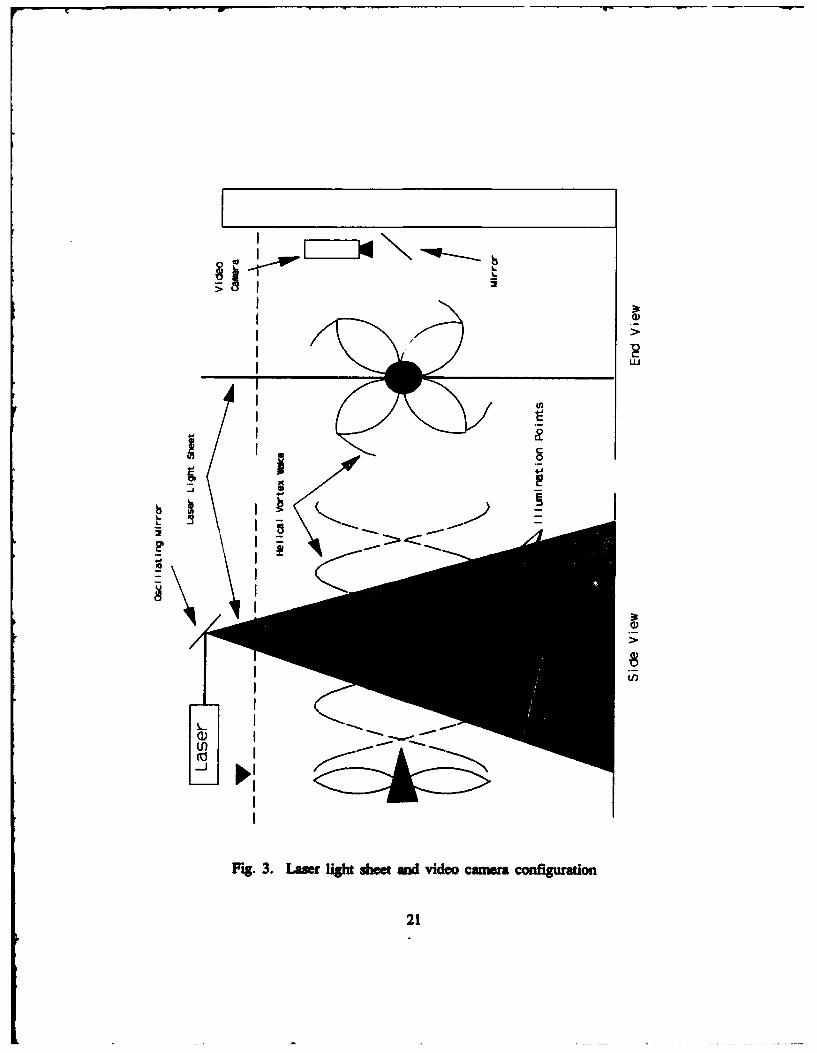
the pod. The fluorescein dye was illuminated using a laser light sheet, positioned as
shown in Fig. 3. The light sheet was created using a 110 mW argon-ion laser directed
into a 30 Hz vibrating mirror. This sheet was fixed (not moving with the carriage) in the
vertical plane and aligned with the propeller axis.
A Sony 3/4 in., 30 frome per second video tape recorder was used to record images
from a high sensitivity black mod white camera mounted on the basin side as shown in
Fig. 3. The images shown here anr, 35 mnm photographs of the video screen.
3
DYE R4JECnON FLOW VISUALIZATON
The dye injection rate was examined to determine its influence on the formation of
the tip vortex. Care was taken to balance the need for maxinmum dye flow rate producing
extended wake visualiaon time with the need for minimum dye flow rate distudne of
the flow in the blade tip region. Selection of an "optimum" dye delivery flow rate was
made after recording wake images under a variety of dye flow rates and propellr rotation
speeds. "Optimum" here was defined as the minimun flow rate giving sufficient dye in
the vortices for sharp contrast to one diame downstream Dye speed variation
about this small flow rate had no apparent influence on the vortex wake. The resulting
flow rate of 0.394 in'/sec (6.45 mI/sec) gave an estimated radial velocity on the blade face
exit point of 16.8 in/sec (43 cm/sec). This exit velocity is approximately one third of the
circumferential velocity at the tip and is oriented in the same direction as the radial flow
induced by the tip vortex. Recall that the dye slot is on the face or "pressure" side of the
blade.
Dye injection rates were increased only in select high speed/low J cases in order to
enhance the video contrast. In these cases, no apparent changes were noticed in the flow,
only sharper contrast in the images. The large variation in exit velocity of the dye caused
by the flow rate change indicated that under these circumstances, the momentum transfer
from the dye exit point had a negligible effect on the formation of the tip vortex.
Car must be taken in interpreting dye roll-up as discrete vortices. As shown by
Hama (1962) and recently by Cimbala et al. (1988), streakline dye patterns show the
integrated motion of the marked fluid from its point of introduction. In the current
experiment, however, local rates of change of the dye rol-up were sufficient to indicate
4
J

persistent vortical -tracture. The continuous change in the dye roll-up provided an accurate
marker of the fluid velocity. Comparison with the velocity field induced by discrete vortex
lines leads to accurate location estimates of the vorticity centers.
WAKE HELIX INSTABILFFY
The most striking feature illustrated in the video coverage in this experiment was
the twisting of vortex structures in pairs resembling a 2-dimensional vortex "pairing"
phenomenon (Ho and Huerre, 1984) in the plane of the laser light sheet. This flow
phm enon will be referred to as vortex twisting and will be described fiuther in the
folowing paragraphs. Fig. 4 shows a time sequence of the helix in 0.1 second increments.
The propeller loading corresponds to J=0.5. The dye spots madding the vortex cores can
be seen to pair up and rotate about each other as the propeller moves further to the right
of the photographs. If the wake were to remain stable and symmetric, the dye spots would
remain roughly equidistant from each other, appearing similar to a discretised vortex sheet.
The movement of these dye spots therefore indicates a loss of symmetry caused by an
unsteady influence on the propeller wake. This type of vortex motion appeared in all of
the operating conditions of this experiment except at the non-loaded advance ratio. Details
of any differences are described in later sections of this report. Although previous analytic
work indicated the inherent instability of helical vortices (Widnall 1972), propeller tip
vortex cavitation observations in water tunnels have shown stable helix forms. To
determine the nature of the observed vortex twisting, an evaluation of possible influences
on propeller wake instability was conducted.
5

Sources of unsteady perturbation on propeller wake flow 5elds are listed below:
a unsteady propeller inflow
b. non-uniform spatial propeller inflow
c. flow asymmetry caused by the free surface
d. unsteady rotation of propeller
e. blade-to-blade variations in loading
It should be noted that item d can be modeled as a combination of items a and b.
Item e, Hiade-to-blade loading variations, could be caused by geometric variations
between the blades, or by variations in the boundary layer flow pattern over similarly
shaped blades. Dimensional measurements of the propeller however, showed very uniform
blade geometries. In addition, no roughness variations were found from blade-to-blade
which might cause boundary layer transition/separation variations.
Since these experiments were conducted in a still water towing tank, the turbulence
level was observed to be extremely low and spatially uniform prior to each run. The
influence of the strut wakes on the wake helix could not be neglected, but appeared to be
insignificant judging by the similarity of vortex twisting in the lower region near the
propeller (no strut effect) to that of the upper region near the propeller (See Fig. 4). The
effect of strut wakes, if any, would be seen in this region. Any inflow unsteadiness was
therefore suspected to be due to carriage motions or propeller drive unsteadiness. Although
vibrations on the carriage were not measured, the same form of unsteady flow was
observed over wide variations in both carriage speed and blade rate frequencies. The
similarity of the flow unsteadiness under these conditions implied a negligibly low
influence of unsteady carriage motions.
6
To determine if an unsteady perturbation of the flow field was being created by the
propeller drive system, careful measurements of the angular motion of the propeller were
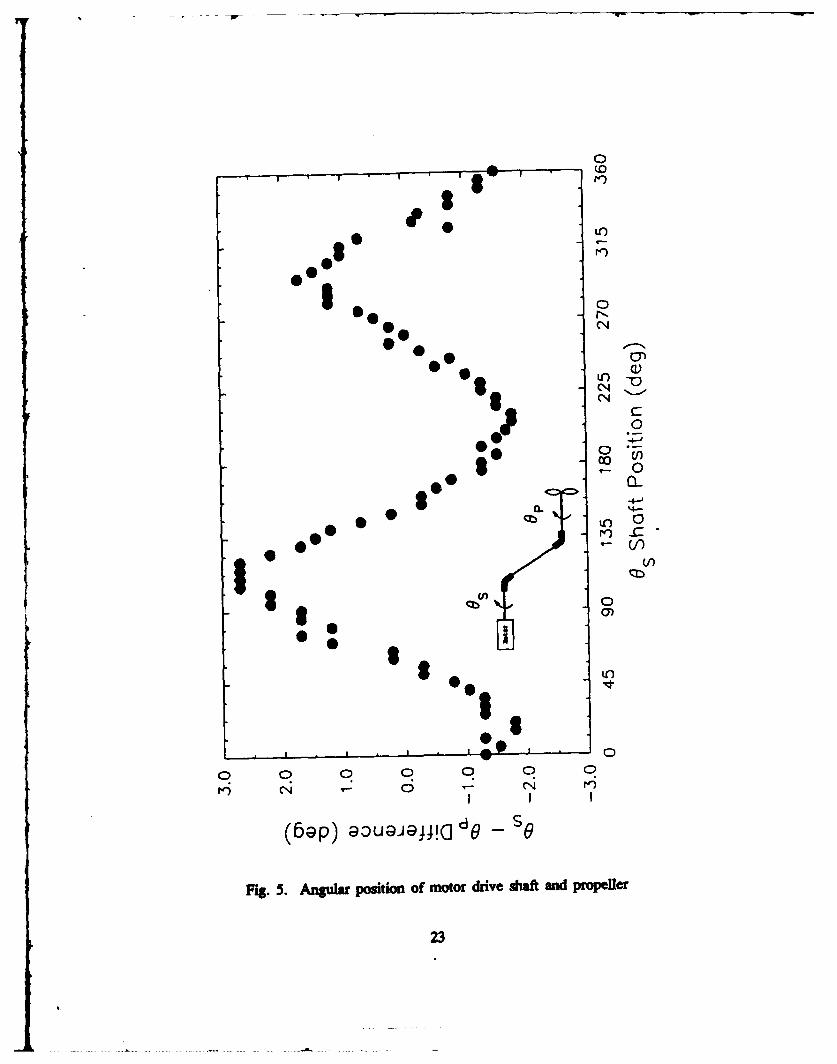
made. Fig. 5 shows results of a comparative measurement of the angular positions of the
motor drive shaft e, and the propeller 0,. The two-cycle nature of the curve is a
characteristic of the non-constant angular transmission of the two inclined universal joints.
Despite their ease in design application, universal joints in this inclined fashion were found
to cause an undesirable unsteady angular velocity.
An analysis shows how this small unsteady angular velocity variation can dominate
the downstream interaction of the propeller tip vortices and could give rise to the vortex
twisting observed in this experiment. The key to the analysis is the coincidence of the
four lobes (upper and lower peaks) in the angular velocity, (o, with the positions of the
four blades of the propeller. A typical sequence of blade passages through a fixed angular
position can help in visualizing the significance of this result.
a. Assume that blade #1 passes throuh the vertical position when the propeller
is operating at the positive peak of o) variation.
b. Blade #2 will pass through the vertical position 90 degrees later, but now the
propeller is operating at the negative peak of angular velocity.
c. Blade #3 passes vertical 180 degrees later and the propeller is again at the
positive peak of o0 similar to when blade #1 passed through the vertical
position.
d. Finally blade #4 passes through vertical with tle minimum o similar to when
blade # 2 passed through vertical.
7

In other words, the 180 degree separation of every other blade synchronizes with the 180
degree separation in positive (or negative) peaks in the angular velocity curve. The net
result is an oscillation (at each fixed angular position) of the instantaneous value of
propeller advance ratio. In this experiment, the light sheet focuses the viewer's attention
on two discrete positions: top and bottom. The visible vortices shed into the wake will
therefore alternate in strength and position based on the advance ratio, J, of the propeller at
the instant the blade passes through the sheet. With these conditions defined, one can
derive a vortex interaction scenario for comparison with the observations.
The fluctuations in J caused by the w oscillation give rise to changes in the axial
compression of the vortex helix geometry. A tip vortex will experience an imbalance in
induced velocity from its neighboring blade tip vortices due to their unequal spacing. If
the closest neighbor vortex is downstream, the net induced motion will be radially inward.
The significance of this inward motion arises from the high radial gradient in axial velocity
in the tip vortex region. This gradient causes filaments of lower radial position to be
convected downstream faster than their partners at higher radial position. This convection
can be visualized in both the 3-Dimensional images of Fig. 6 and the laser light sheet
images (see Fig. 4). Note in Fig. 4 the relative movement of the dye spots labeled "I"
and "2". Despite their similar motion to vortex "pairing", it should be remembered that the
twisting process as shown in Fig. 6 is very 3-dimensional.
The continued interaction of the vortices once they have been shed was seen to be
dependant on the propeller loading and is discussed further in the PROPELLER LOADING
VARIATION section.
8
The dominance of unsteady angular velocity in the propeller wake will be
eliminated in future experiments through the use of constant velocity joints. Despite the
inclusion of this unsteady w variation, the results obtained from the present study will be
useful in the study of propeller wakes near a free surface.
PRESENTATON OF RESULTS
REYNOLDS NUMBER DEPENDENCE
Experimental measurements such as (Cook, 1972) have shown that tip vortices can
be modelled with finite radius viscous cores, outside of which the flow behaves in an
inviscid manner. The existence of a viscous core leads one to examine the Reynolds
number dependence of results utilizing visualization of these vortices. A series of cases
was therefore recorded for several carriage speeds while varying the rpm to maintain the
same advance coefficient, 1. The resulting increase in flow speed over the blades could
therefore be examined without changing the flow angle of attack. This allowed observation
of wake variations due to viscous effects. This comparison was made only with the deep
model submergence (minihizing Froude number effects due to free surface waves).
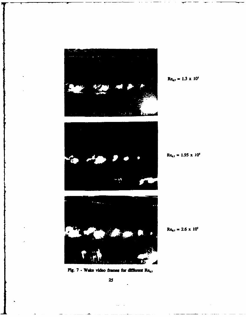
Fig. 7 isolates the upper row of wake vortices at J=0.8 for three different ReW
ranging from -1.3 x 10 to -2.6 x 10. Although the rate of dye diffusion is greater for
the higher Rea,, the tMjectory and pairing of the vortices are essentially the same. This
indicates that under the conditions of this test, the Reynolds number effects were
overshadowed by the effect of the angular velocity variation described previously in the
WAKE HELIX INSTABIITY section.
Reynolds numbers (Rek,) for the propeller varied from -5 x 10' to -1.5 x 10' for a
carriage velocity of 1 ft/s. Meyne (1972) reports, for similar 4-bladed propellers, the
9

presure sde remained laminar up to Re,, = 8 x 10', and the suction side remained
laminar between Re, = 2 x I0' and Re6 , - 3 x I0', depending on advance coefficient.
This suggests that the visualization data for the 1 ft/sec carriage speed corresponds to
laminar flow over the entire propeller.
As the Reynolds number is increased, the laminar tip vortices will transition to
turbulent flow at smaller axial distances downstream (see Fig. 7). In order to reveal any
effects of laminar to turbulent vortex transition on the wake interaction process, however,
the propeller drive modifications to remove unsteady o) variations will be needed. The
constant propeller angular velocity should give rise to a more symmetric vortex wake,
increasing the importance of viscous and gravitational forces in the wake vorticity
kinematics.
PROPELLER LOADING VARIATION
The principal parameter varied through this experiment besides the propeller
submergence depth was the propeller loading condition. This was done by holding the
carriage speed constant and changing the rotational speed of the drive shaft. This changed
the advance ratio, J, representing the angle of attack and resultant loading on the propeller
blades. By systematically observing the wake under various loading conditions, wake
behavior for variations in propeller jet strength could be evaluated.
The comparison in Fig. 8 (Q ranging from 0.8 to 0.4) shows the strong dependence
on I of the vortex twisting process. The most obvious effect of lowering J is the decrease
in streamwise length scale (or time scale) of the twisting motion. The apparent synmnetry
between the top and bottom rows of vortices indicates negligible influence of the free
surface or the support struts at this deep submergence depth (zJR=2). The influence of
10
propeller loading on the vortex interaction process was therefore pursued through closer
exanination of wake images under various J conditions.
Since J was usually varied by changing propeller shaft angular velocity under a
constant carriage speed, the influence of unsteady rotation caused by the universal joints
would also need consideration. The influence of angular velocity on J can be detennined
from the definition. J = U / (nD) = 2xU / (01). Computation of the helical vortex
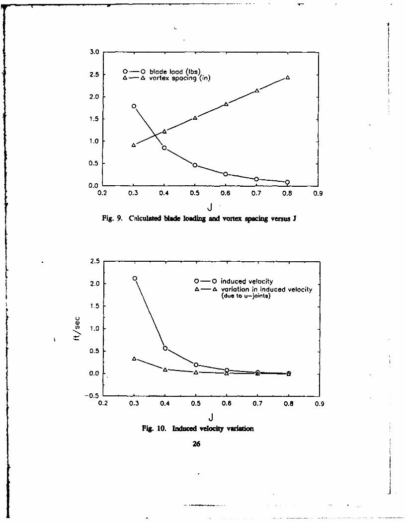
spacing for each J can be made using simple geometry. Estimates of the propeller blade
load can also be made using the open water propeller loading curves. The trends in
calculated vortex spacing and blade loading for variations in J are shown in Fig. 9. An
estimate of the tip vortex strength can be made using the blade loading by assuming that
all of the bound vorticity in the blade is shed and rolled up into the tip vortex. The tip
vortex strength is known then from: r = L(pU) (where: L = lift force on blade / span
of blade). Note that the lift force on the blade can be estimated from the open water
curves for a known I value. Combining the estimated vortex strength and separations with
the Biot-Savart law gives estimates of the induced velocity of the vortices. Computed
trends in the wake vortex-induced velocity with respect to I are plotted in Fig. 10.
Induced velocities calculated here utilize simplified assumptions of low vortex curvature
(essentially 2-dimensional) but illustrate the trend of a full 3-dimensional analysis. Note
especially the increasing trend in induced velocity between the vortices as J is reduced.
The higher induced velocities at low J values speed up the twisting process once
perturbations are applied. The effect is similar to the growth in numerical instability of
fdammt models of vortex sheet motions as the filament spacing is reduced or strength
increased as described in Moore (1971).
11
Us this induced velocity vend, a streamwise length scale can be calculated and
cmpared with length scale munt fomn the video images. Th measurement used
for comparison is the streamwise distance from the propeller plane to the plane where a
vortex pair has first reached a vertical orientation. Fig. I I shows a comparison of
calculated length scale (nonnalized to match the measured data at J=0.5) with the measued
length scale. The agreement is reasonably good considering the calculations are derived
from a 2-dimensional model of the vortex interaction, and neglects the increase in induced
velocity caused by the unsteady shaft rotation at lower J (see Fig. 10) and decrease in
induced velocity caused by sell-induced velocities of curved vortex filaments. The
calculations at the very least confirm that the twisting length should be reduced as J is
reduced.
An additional difference in the vortex interaction was noted at the lower I values.
At =0.4 the larger radial gradient in streamwise velocity near the edge of the propeller jet
causes the inboard vortices to be swept downstream past their original partner to interact
with the second vortex encountered. Images of reduced contrast at i=0.3 suggest that the
vortices are swept to the third outboard partner downstream before interacting to swing out
of the jet stream. Turbulent diffusion of the dye under these conditions, however, reduces
the detectability of organized vorticity in the high velocity fluid.
It should be noted here that this strong wake instability should be greatly reduced in
future experiments with constant propeller rotation. Despite the elimination of the shaft
velocity pesnubation, future experiments are expected to show strong dependence of the
prope.ll" wake evolution on J. This dependence stems from te inherent instability of the
helix to perturbations (Widall 1972), and the decrease in vortex spacing as J is decreased.
12
In particular, it will be interesting to note the variation in free surface influence on the
breakdown of the helical form of the propeller wake as J is modified.
PROPELLER DEPTH VARIATION
Variation in the submerged depth of the propeller gave rise to two mutually
interacting effects in the wake of the propeller. First, variations in wake vortical structure
downstream are influenced by the presence of the free surface boundary condition. In
addition, the free surface elevation is modified by surface piercing model support struts and
local flow fluctuations. These local flow fluctuations are caused by proximity of either the
propeller blades or their tip vortex wakes. The two depth variation influences will be
treated separately in the sections to follow.
PMoLrj wake Influence
The influence of the free surface on the vortical structures in the propeller wake
appeared in this experiment in two forms. Variations in both the vortex trajectory and the
size/brightness of the vortex spots were noted between the top and bottom illuminations of
the wake. These variations were amplified as J or the non-dimensional submergence depth
(r.R) were decreased.
A study of Fig. 12, showing a time sequence separated by 0.1 seconds at i=0.5 and
zJR=l.25 indicates the variation in vortex trajectory caused by proximity to the free
surface. In this sequence the vortex labeled "I" moves much faster over the top of its
partner labeled "2" than the coeskondng vortex 3 moves below vortex 4. This difference
could be a result of:
I. stronger vorticity in vortex I or 2 than in vortex 3 or 4(possibly due to reduced dispaton)
13

2. Stronger shear layer on top with respect to bottom (possibleslight reverse flow on top due to zero friction boundarycondition at surface)
Note that the movement of vortices "2" and "4" is relatively mUl.
Also notable in Fig. 12 is a distinct difference in both the shape and brightness of
the dye spots marking the tip vortices. As mentioned earlier in the PROPELLER
LOADING VARIATION section, the support struts show no influence on the dye
visualization. The authors speculate, therefore, that the difference in dye diffusion between
the top and bottom vortices is indicative of an influence of the free surface on the
turbulent uumasition of the vortices. This is suggested by the stronger diffusion of dye near
the edges of the vortices while the center spot stays bright longer. Velocity measurements
in future experiments will shed light on this process.
Free Surface Infinene
As mentioned earlier, the free surface elevation can be modified by the presence of
several types of ditrbne.
The model support struts piercing the free surface leave waves similar to those left
by ships. These waves are dependent on the Froude number based on the speed of the
carriage and chord length of the strut. Observations of the wave patterns behind the struts
were made at a series of speeds between I and 4 ft/sec (0.305 and 1.22 m/sec) at the
shallow submergence depth of zJR=1.25. During these observations the J was set to
1.045 cor e ing to the zero thrust condition for the purpose of minimizing propeller
blade and wake effects on the free surface. These effects were examined separately as
described in the next paragraph. The waves generated by the struts and pod are
crtized in Table I below. The short wavelength trasverse waves generated at 1
14

ft/ec (0.305 m/uec) decreased to an undetectable amplitude upstream of the propeller plane.
In addition to increased dye visibility at this speed, the low strut influence was also a
factor in conducting most of the observations at this speed.
The free surface effects due to propeller blade and wake vortex proximity were
amplified expectedly as either the propeller suIb n was decreased or the blade
loading was increased. At z,/=l.25 surface depressions caused by blade passage became
deep enough (for 1<0.4) to draw air from the surface and send it bubbling through the
wake. It should be noted that this ventilation process was clearly distinguishable from a
cavitation phenomenon which was not observed.
Surface seeding proved to be a limitation in examining the deflections at the
air/water interface caused by wake vorticity. Dust particles proved to be very helpful in
surface visualization. Strong currents created near the surface by the submerged vorticity,
however, quickly cleared most of the particles deposited there. Remaining particles did
indicate correlated free surface deflections with the dye marked vorticity below. The
dynamic nature of the video image is necessary however to fully appreciate this correlation.
Variations in the laser light intensity, caused by refraction angle changes at the free surface
deflections, were also sensitive measuments of the influence of submerged vorticity on
the free surface profile. When viewing the videotape, varying intensity bands in the laser
light sheet can be traced to surface deflections. The small amplitude of these surface
deflections under the conditions of this experiment are usually very difficult to see
individually without the aid of these light rays.
15

WAKE PERSISTENCE
An important motivation for this experiment was the examination of the persistence
of the propeller wake a long time after the propeller had passed. Because only flow
visualization m u e were being made, and the luminescence of the dye decreased
below the video camera threshold after approximately 40 seconds at low I and 60 seconds
at high J, no long term wake data could be recorded. To the eye; however, the fine dye
gradients could be observed for over 4 minutes. Conments made here, will therefore be
based on visual observations of the wake made by the authors during the actual testing.
Two characteristic features were observed in the far wake of the propeller and they are
described below.
The first feature noticed was the slow migration of the propeller wake jet towards
the free surface. Once wake contact was made with the free surface, higher momentum
fluid quickly moved upward forming strong axial surface currents. These currents were
visible in movement of both the dye-diluted fluid near the surface and dust particles on the
air/water interface. The downstream length for surface contact of the propeller wake with
the surface (,) is dependant on I and 7,,. The advance ratio essentially detennines the
wake spreading angle P, while z/R defines an initial depth of the wake. The accurate
maurement of k4 requires a precise and sensitive criterion for evaluating the wake/free
surface interaction point. The velocity field due to a vortex, however prevents the
definition of some range, beyond which no interaction exists. In future velocity
measurement experiments, a threshold value for vortex wake induced velocities at the free
surface will therefore be defined to signal an end point for 14. Measurnent of 0 was
awned in ths experiment by the special variation in the wake edge caused by the
16
vortex twisting. A more analytic evaluation of the interdependence of these variables will
theefore require additional planned in the future.
Another feature noticed in the far wake was the intermittent occurrence of large
turbulent structures long after the propeller had passed and most of the turbulent motion
had diffused to low intensity. In several cases these structures were noticed up to 40
propeller diameters downstream. Velocity ma Ir -Int may show additional intermittent
turbulent structures of low intensity much farther downstream. It is not known what effect
the improvement in propeller drive smoothness will have on the existence or strength of
these persistent turbulent structures.
DISCUSSION AND RECOMMENDATIONS
The experiment described here included video recording of a range of propeller
loadings and carriage speeds. In addition, limited video coverage of the 3-dimensional
form of the helix was also obtained. The 3-dimensional form of the helix (Fjz. 6) shows
qualitatively the form of the instability present in the data reported in this paper.
Great care was taken to align the universal joints in setting up the experiment. No
visual sign of the variation could be seen in the propeller even with a strobe light.
Detailed mesuren described in the HEM INSTABILITY section showed however a
2.5 degree amplitude sinusoidal variation in the propeller shaft position causing blade
loading and wake helix geometry variations of significant magnitude. An upgrade in the
propeller drive design utilizes miter gears which will give constant velocity at the propeller
shaft. A retesting of the propeller with the new drive gears will be carried out.
The authors suspect that once the shaft velocity variation is eliminated, a weaker
instability will still be present in the wake helix due to either the free surface effects or
17
vortex breakdown. These influences should be more prominent in future experiments.
Comparison of images from this experiment with those of round jet shear flows suggest
that helical vortex geometry in the presence of its own strong shear layer may be unstable.
The implications of wake helix instability could have a significant effect on
numerical wake analysis codes. The generation of more representative input mean and rms
velocity files may be augmented by information on the spatial vorticity distribution. The
presence of large scale vortical structures seen far downstream in the wake could play a
significant role in energy storage and transfer to the free surface. The intermittent nature
of these structures, however, may prevent accurate wake modeling by mean and mns
quantities currently being used. The simultaneous use of flow visualization and Laser
Doppler Velocimetry in future experiments will permit cost effective evaluation of the
importance of these structures and their interactive nature with the free surface.
18

dye slot cut in blade face
spanwise extent oftape coverage
hole through Propeller hub
hole throughdrive shaft!I tape Covering dye slot
Fig 1. Four bladed propeller with hollow hub and dye slotted blades
19

0P4
.P4
0
Fig 2. Experimiental configuration
20
c1U
0.4
Fig. 3. Laser U&gh sheet and video camera configuration
21
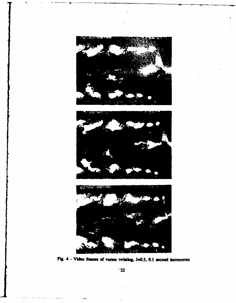
MSg. 4- Wodo Orun of vot~ "twhi, i=-5S, 0.1 mcod hicremt
'22
S - -----N,
0
*@ 00
0- 4
V)
'-0
C)'
(ba ) aDajaj~a d s
Fig 5.Aglrpsto0fmtr)rv hf i rpfe
*2
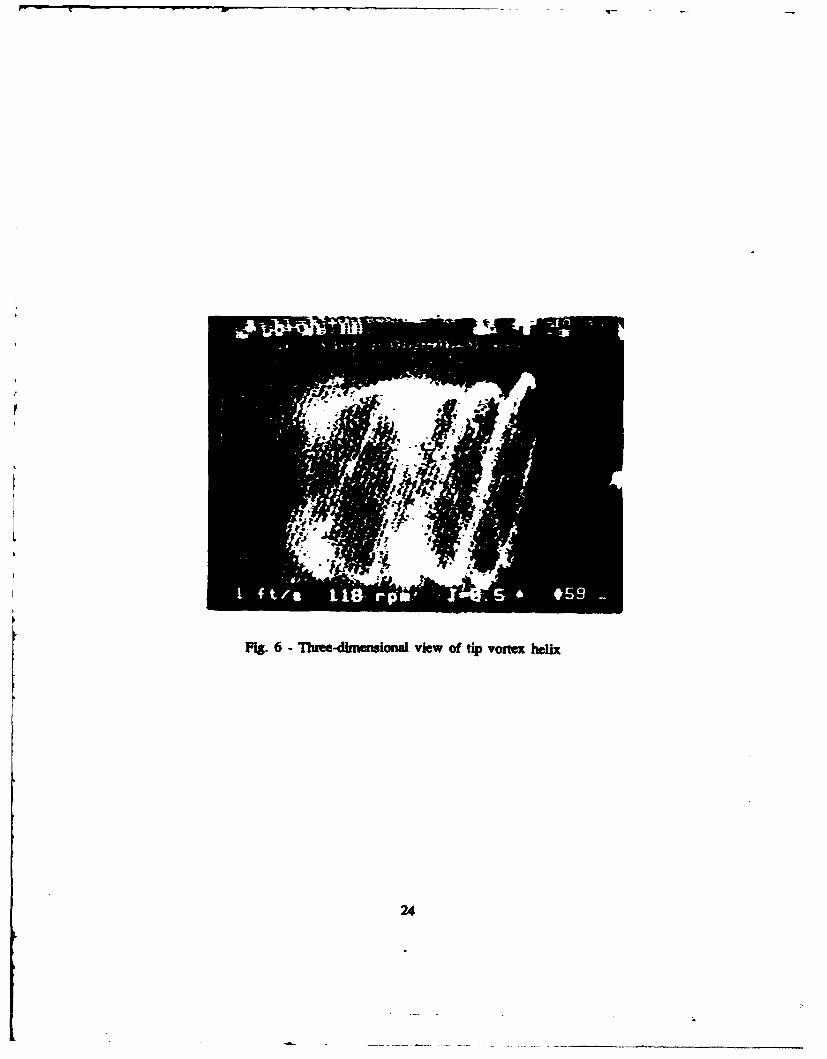
Pis. 6 - Theet-dimensional view of tip vomtx heli
24
Re,?- 1.3 x 10'
Rk.7 =1.95 x10'
Re,, 2.6 x 10'
Pis. 7 - Wdcs video f~Ii for' M Rte,
25
0-0 blade load (Ibs)2.5 A-Avortex spacing (in)A
2.0A0
1.5 A .,
0.50
0.00.2 0.3 0.4 0.5 0.6 0.7 0.8 0.9
Fig. 9. Calculated blade loading and vortex spacing versus I
2.5
2.0 00-0 induced velocityAAvariation in induced velocity
(due to u-jorits)
1.5
00
0.50
-0.50.2 0.3 0.4 0.5 0.6 0.7 0.8 0.9
Fig. 10. Induced velocity variation
26

Ia0.8
J 0.6
I m 0.5
J 0.4
Fig. 8 - W Ig~ko J yuimdam, &MJR-2.7.

0
0
0
1 0
(0
00
u E)
04
it
(ul) 0100S Lflbugl 6uIIs!mi xOIJOA
Fig 11 Coinuso ofcalulaedandmeaure sreamwise wake lnt cl
28
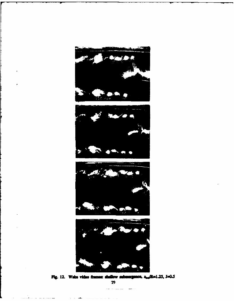
Fg.12. Wa.is 0mm.t dimn mu .. um, .29

Table 1. Free surface effects due to strut and pod: z,.JR=l.25
Carriag Speed Wave Pattern(ft/ecC)
I Short 1.5 in. (4 cm) wavelength divergent waves due to theMIMI, wriplitude < 0.5 in. (1 cm).
2 Diveirging and trazvems waves of approximately 8 in.(20 cm) wavelength - 0.75 in. ( 2 cm) amplitude.
3 Dominaint transverse wave systemn due to pod: wavelength m2 ft (0.6 m) and amplitude - 0.8 in. (2 cm) due to pod.
4 Dominant transverse wave system: wavelength -- 3.5 ftr (1.1 m) and amplitude -I in. (2.5 cm) due to pod.
30

REFERENCES
Blanton, J.N., and S. Fish (1988), "Near and Far Field Propeller Wake Study Using LaserDoppler Velocimetry", DTRC/SHP-1268-01.
Cimbala, J.M., H.M. Nagib, and A. Roshko (1988), "Large structure in the Far Wakes ofTwo-dimensional Bluff Bodies", J. Fluid Mech., vol. 190, pp. 265-298.
Cook, C.V. (1972), "The Structure of the Rotor Blade Tip Vortex", AGARD Proceedingson Aerodynamics of Rotary Wings.
Fish, S. and J.N. Blanton (1988) "Propeller Wake Flow Visualization Near a Free Surface",DTRCISHP-1268-02.
Greeley, D.S., and J.E. Kerwin (1982), "Numerical Methods for Propeller Design andAnalysis in Steady Flow", SNAME Transactions, vol. 90, pp 415-453.
Hama, F.R. (1962), "Streaklines in a Perturbed Shear Flow", Physics of Fluids, vol. 5,number 6.
Ho, C.M., and P. Huerre (1984), "Perturbed Free Shear Layers", Ann. Rev. Fluid Mech.,vol. 16, pp. 365-424.
Kuiper, G. (1979), "Modeling of Tip Vortex Cavitation on Ship Propellers", 4' LipsPropeller Symposium, Drunen-The Netherlands.
Lugt, HJ. (1959), "Einfluss der Drallstromung auf die Durchflusszahlen genormterDrosselmessgerate", PhD Thesis, Stuttgart, Partially translated by the BritishHydromechanics Research Association, Rep. T 716 (February 1962).
Lyden, J.D., D.R. Lyzenga, R.A. Shuchman, and E.S. Kasischke (1985), "Analysis ofNarrow Ship Wakes in Georgia Strait SAR Data", E.R.I.M. report # 155900-20-T, AnnArbor, Ml.
Moore, D.W. (1971), "The Discrete Vortex Approximation of a Finite Vortex Sheet", Calif.Inst. Tech. Rep. AFOSR-1804-69.
Meyne, K. (1972), "Investigation of Propeller boundary-layer flow and Friction Effect onPropeller Characteristics", DTNSRDC Trans-352.
Widnall, S. E. (1972), "The Stability of a Helical Vortex Filament", J. Fluid Mech., Vol.54, Part 4.
31