c series travellers - irrigation systems, manure … · c-series traveller ... time provided you...
TRANSCRIPT

TR-MAN-C123
C Series Travellers
OPERATOR'S and MAINTENANCE
MANUAL 2011 Edition


Title
TR-MAN-C123
Cre
atio
n 05-JAN-2011 by
Ivon LeBlanc
Rev
isio
n
Operator's Manual - C-Series
Page 1 of 56 Cadman Power Equipment ▪ BOX 100, Courtland, Ontario, Canada N0J-1E0 ▪ Phone: 519-688-2222 ▪ Fax: 519-688-2100 ▪ www.cadmanpower.com
Table of Contents Table of Contents ................................................................................................. 1
C-Series Traveller ................................................................................................. 3
Warranty Policy .................................................................................................... 4
Safety Precautions ............................................................................................... 5
Safety Decals ....................................................................................................... 6
Planning Your Application .................................................................................... 8
Example of Retrieve Rate Selection ................................................................... 12
When Applying Liquid Manure ............................................................................ 15
Equipment Set-up ............................................................................................... 16
iWater™ Controller Instructions .......................................................................... 25
Basic Pull ............................................................................................................ 27
Advanced Pull ..................................................................................................... 30
Control Panel ...................................................................................................... 39
Service Panel ..................................................................................................... 46
Engine Drive Option ........................................................................................... 48
Turbine Drive Option .......................................................................................... 50
Required Maintenance ....................................................................................... 51
Technical Specifications ..................................................................................... 54
Useful Information .............................................................................................. 56

TR-MAN-C123 Operator's Manual - C-Series
Page 2 of 56 Cadman Power Equipment ▪ BOX 100, Courtland, Ontario, Canada N0J-1E0 ▪ Phone: 519-688-2222 ▪ Fax: 519-688-2100 ▪ www.cadmanpower.com
TR-MAN-C123 Operator's Manual - C-Series
Page 3 of 56 Cadman Power Equipment ▪ BOX 100, Courtland, Ontario, Canada N0J-1E0 ▪ Phone: 519-688-2222 ▪ Fax: 519-688-2100 ▪ www.cadmanpower.com
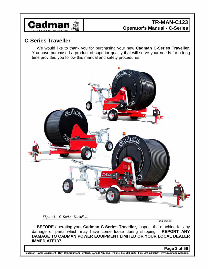
C-Series Traveller We would like to thank you for purchasing your new Cadman C-Series Traveller.
You have purchased a product of superior quality that will serve your needs for a long time provided you follow this manual and safety procedures.
Figure 1 – C-Series Travellers img-00410
BEFORE operating your Cadman C Series Traveller, inspect the machine for any damage or parts which may have come loose during shipping. REPORT ANY DAMAGE TO CADMAN POWER EQUIPMENT LIMITED OR YOUR LOCAL DEALER IMMEDIATELY!

TR-MAN-C123 Operator's Manual - C-Series
Page 4 of 56 Cadman Power Equipment ▪ BOX 100, Courtland, Ontario, Canada N0J-1E0 ▪ Phone: 519-688-2222 ▪ Fax: 519-688-2100 ▪ www.cadmanpower.com
Warranty Policy CADMAN POWER EQUIPMENT LIMITED warrants that each machine it
manufactures shall be free from defects in materials and workmanship. The terms of this warranty are as follows:
All components manufactured by CADMAN POWER EQUIPMENT LIMITED shall be warranted for a period of one (1) year from the date of delivery, except the frame and hose drum structures which shall be warranted for a period of three (3) years.
The polyethylene hose used on CADMAN HARD HOSE DRAG REELS will be warranted for a period of five (5) years from the date of delivery, on a pro-rata basis. The schedule for the polyethylene hose warranty is as follows: 1st to 10th month from the date of delivery is 100% 11th to 60th month from the date of delivery, the warranty shall diminish from 100% to 0% at a rate of 2% per month.
CADMAN POWER EQUIPMENT LIMITED makes no warranty whatsoever in regard to tires, engines, and other trade accessories used on its equipment. The customer shall rely solely on the warranties offered (if any) by the respective manufacturer of these trade accessories.
The sole obligation to CADMAN POWER EQUIPMENT LIMITED under this warranty is limited to the repair or replacement of any part it manufactured, which, in the judgment of CADMAN POWER EQUIPMENT LIMITED, failed under normal and proper use and maintenance due to defective materials or workmanship. All freight charges incurred shall be the sole responsibility of the customer.
CADMAN POWER EQUIPMENT LIMITED and its dealers (who are neither authorized nor qualified to undertake any obligations on behalf of CADMAN POWER EQUIPMENT LIMITED) DO NOT, under any circumstances, accept any responsibility for any losses or costs incurred due to parts failure and/or delays during the parts replacement process.
This warranty will be considered void if any alterations or modifications have been made to the machine without the express written consent of CADMAN POWER EQUIPMENT LIMITED outlining the nature and the extent of such modifications.
CADMAN POWER EQUIPMENT LIMITED, whose policy is one of continuous improvement, reserves the right to change specifications and designs without notice or incurring obligation.
The warranties expressed herein are non-transferable and replace any other warranties, either written or verbal, which may have been given or implied.

TR-MAN-C123 Operator's Manual - C-Series
Page 5 of 56 Cadman Power Equipment ▪ BOX 100, Courtland, Ontario, Canada N0J-1E0 ▪ Phone: 519-688-2222 ▪ Fax: 519-688-2100 ▪ www.cadmanpower.com
Safety Precautions Please take the time to read and understand this manual so that
unnecessary errors and risks are avoided. If you have any questions or concerns, please contact Cadman Power Equipment Limited or your local dealer/distributor.
DO NOT move or operate this machine until you have read and understand these instructions in this manual.
NEVER allow untrained persons to operate this machine. DO NOT attempt to service this machine while it is in
operation. MAKE CERTAIN all mechanical, electrical and hydraulic
tension has been released before attempting any service on the machine.
CHECK all fasteners (nuts and bolts) regularly for tightness. PERFORM REQUIRED MAINTENANCE as prescribed or as
necessary to keep this machine in safe operating condition. KEEP ALL SPECTATORS at a safe distance. STAY CLEAR of high pressure supply lines, especially when
first pressurizing the system. STAY CLEAR of power lines. Contact with power lines with
irrigation water or liquid manure WILL result in the machine being a conductor of electricity.
DO NOT remove or alter any shielding on this machine. BE CERTAIN that the machine is securely anchored (using stabilizer legs) before
unwinding the hose. KEEP CLEAR of all moving parts. NEVER tow this machine at speeds greater than 10 mph [16 km/h] and be certain
the tow vehicle has adequate braking capacity to maintain safe control at all times. NEVER tow this machine with the hose loaded with fluid. BE AWARE of any obstacles (i.e. mail boxes, fence posts, and other equipment)
that you may encounter when transporting the machine. REGULAR INSPECTION of your pipe couplings, tubing and gaskets should be a
part of your regular set-up routine. Any defective parts MUST be replaced or repaired before the machine is put into service.
This symbol, the safety-alert symbol, indicates a hazard. When you see the safety-alert symbol in this manual, make sure you completely understand and follow the given instructions or warnings.
Safety is just a word until put into practice.
Safety must be the first thing on your mind when operating any piece of machinery.
Failure to follow all safety instructions can result in serious injury or death to you and/or any spectators.
TR-MAN-C123 Operator's Manual - C-Series
Page 6 of 56 Cadman Power Equipment ▪ BOX 100, Courtland, Ontario, Canada N0J-1E0 ▪ Phone: 519-688-2222 ▪ Fax: 519-688-2100 ▪ www.cadmanpower.com
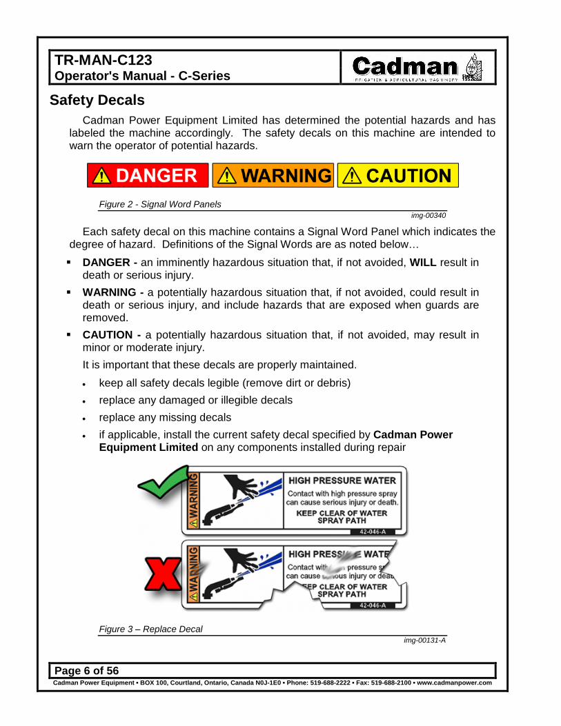
Safety Decals Cadman Power Equipment Limited has determined the potential hazards and has
labeled the machine accordingly. The safety decals on this machine are intended to warn the operator of potential hazards.
Figure 2 - Signal Word Panels img-00340
Each safety decal on this machine contains a Signal Word Panel which indicates the degree of hazard. Definitions of the Signal Words are as noted below… DANGER - an imminently hazardous situation that, if not avoided, WILL result in
death or serious injury. WARNING - a potentially hazardous situation that, if not avoided, could result in
death or serious injury, and include hazards that are exposed when guards are removed.
CAUTION - a potentially hazardous situation that, if not avoided, may result in minor or moderate injury. It is important that these decals are properly maintained. • keep all safety decals legible (remove dirt or debris) • replace any damaged or illegible decals • replace any missing decals • if applicable, install the current safety decal specified by Cadman Power
Equipment Limited on any components installed during repair
Figure 3 – Replace Decal img-00131-A
TR-MAN-C123 Operator's Manual - C-Series
Page 7 of 56 Cadman Power Equipment ▪ BOX 100, Courtland, Ontario, Canada N0J-1E0 ▪ Phone: 519-688-2222 ▪ Fax: 519-688-2100 ▪ www.cadmanpower.com
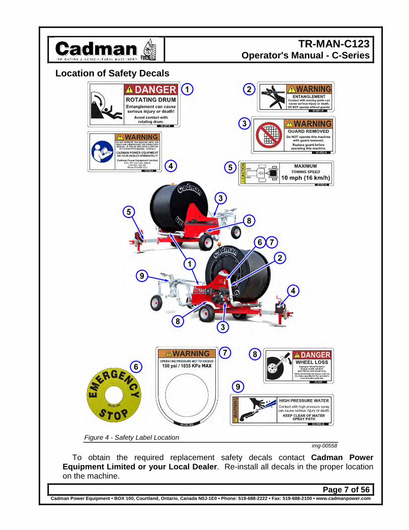
Location of Safety Decals
Figure 4 - Safety Label Location
img-00558
To obtain the required replacement safety decals contact Cadman Power Equipment Limited or your Local Dealer. Re-install all decals in the proper location on the machine.

TR-MAN-C123 Operator's Manual - C-Series
Page 8 of 56 Cadman Power Equipment ▪ BOX 100, Courtland, Ontario, Canada N0J-1E0 ▪ Phone: 519-688-2222 ▪ Fax: 519-688-2100 ▪ www.cadmanpower.com
Planning Your Application You will benefit from having an accurate plan to follow before you set-up or operate
your equipment. When creating your plan, remember that a properly planned field layout will cover the most area with the least amount of set-up time.
Field Preparation: 1. Determine the depth of application in inches.
Irrigating deeper than the root zone is considered over watering. This will result in lost productivity and adds to the overall cost of irrigation.
Figure 5 - Root Zone - Depth of Application img-00197
2. Divide your field into the least number of sections to obtain complete coverage. First determine the area you plan to irrigate. If your field width is greater than
what can be achieved with one (1) pull you will be required to divide the field into the least number of sections to reduce setup time. Use the performance data tables (see Table 1 on page 13) of your sprinkler to determine the coverage of your Traveller.
C Hose Length 2300XL-B=1000' (305 m) 2700XL-B=1285' (392 m) 3000XL-B=1475' (450 m) 2300XL=1150' (350 m) 2700XL=1410' (430 m) 3000XL=1675' (510 m) 2500=1082' (330 m) 3000=1050' (320 m) 3300=1475' (450 m) 2700=1000' (305 m) 3250=975' (297 m) 3500=1320' (402 m) 3000S=700' (213 m) 3500S=900' (275 m) 3700S=1150' (350 m) 4000S=1000' (305 m)
A = Total Irrigated Length / B = Sprinkler Diameter of Throw / C= Length of Hose (maximum)
Figure 6 - Reel Coverage img-00193
You MUST leave as a MINIMUM one (1) coil of hose on the drum at all times. Failure to do so WILL result in hose damage.

TR-MAN-C123 Operator's Manual - C-Series
Page 9 of 56 Cadman Power Equipment ▪ BOX 100, Courtland, Ontario, Canada N0J-1E0 ▪ Phone: 519-688-2222 ▪ Fax: 519-688-2100 ▪ www.cadmanpower.com
Several nozzle sizes are supplied with the sprinkler. The “best” nozzle choice for application may take some experimentation to determine. Typically, two nozzle sizes will perform well for each model.
Customize your application by choosing the right nozzle and pressure combination to accommodate the area to be irrigated. Changing the nozzle size and adjusting the pressure setting can improve your irrigation plan.
Avoid quarter circle (partial pattern) operations while irrigating. During quarter circle operation, sprinkler thrust tends to steer the sprinkler cart in the direction of the water being thrown. Reduce the size of the sprinkler nozzle and pressure to reduce the diameter of spray. Remember the retrieve rate WILL require adjustment to accommodate the reduced flow.
Figure 7 - Avoid Quarter Circle Applications img-00199
If conditions dictate that a quarter circle (partial pattern) pass is unavoidable, prepare the travel lane with a shallow trench for the hose to follow. Adding extra weight to the rear of the sprinkler cart is also beneficial. If these preparations are not possible or prove inadequate you must adjust your plan to allow for a full spray pattern.
During normal operation, (full pattern the sprinkler operates to both sides of the cart) sprinkler thrust will correct this steering action automatically. The side to side movement of the cart should be no more than the width of the carts rear tube (where hose and sprinkler cart are connected).
There are two (2) reasons for this.
(1) Even divisions of the field allow maximum versatility to combat rising winds from any direction.
(2) The sprinkler cart will track straight and be less affected by sprinkler thrust.
img-00200

TR-MAN-C123 Operator's Manual - C-Series
Page 10 of 56 Cadman Power Equipment ▪ BOX 100, Courtland, Ontario, Canada N0J-1E0 ▪ Phone: 519-688-2222 ▪ Fax: 519-688-2100 ▪ www.cadmanpower.com
3. If a curved pull is necessary. If you are required to curve the hose, pull a minimum of 200 feet [61 m] of
hose straight out from the machine prior to beginning a long gradual curve. The arc or curve must not form a ninety degree (90°) bend.
The hose will naturally take the shortest path (a straight line). Without resistance such as a contour, trench or a furrow the hose will tend to straighten. The sprinkler cart will make contact with any obstacle if there is no resistance. Failure to provide a form of resistance will result in serious equipment damage and could result in injuring you and/or your spectators.
4. Plan to leave open travel lanes and ample head lands. If you typically hill your row crops and plan to leave open travel lanes, hill and
cultivate your travel lanes as well. The absence of grass and weeds will dramatically reduce the amount of towing effort and traction required to pull out the hose. The hills will also help guide the hose and cart through the field. Provide ample head land (lane way) space to allow the machine chassis to be pivoted and setup.
5. Some crops provide a great deal of resistance. Crops such as sod, alfalfa, potatoes and peas provide a great deal of
resistance to pulling the hose. If you irrigate such a crop, consider uncoupling the feeder hose at the mainline valve and pull out the hose slightly slower. This WILL expel a great deal of water from the P.E. (polyethylene) hose, reducing the amount of towing effort required.
It is possible that the machine will expel several hundred gallons/litres of water. Use good judgement to prevent excessive muddying of the area near the chassis of the machine.

TR-MAN-C123 Operator's Manual - C-Series
Page 11 of 56 Cadman Power Equipment ▪ BOX 100, Courtland, Ontario, Canada N0J-1E0 ▪ Phone: 519-688-2222 ▪ Fax: 519-688-2100 ▪ www.cadmanpower.com
6. Determine the best position for your reel in each section. The best start position for your reel is at the center of the furthest section
away from the source of water. (See Figure 8) By doing this your subsequent setups will not require additional water source changes.
Figure 8 - Multiple Pass Setup img-00233
Where field conditions permit, always attempt to pull the hose either up or down sloping terrain instead of operating on the side of a hill. If a side hill condition is unavoidable, provide a hilled trench as a guide for the hose and add extra weight to the sprinkler cart to prevent upset.
If a trench is not created the hose will slide down the hill. After introducing water, the hose will become much heavier. Failure to provide a trench will result in serious equipment damage and could result in injuries to you and/or spectators. Obstacles will play a big part in the planning process. If an obstacle interferes
with the area to be irrigated an adjustment to the plan will be required.
Figure 9 - Obstacles in plan img-00234
7. Determine the retrieve rate. With your sprinkler data chart, system pressure, field width and desired
application depth you can choose the retrieve rate. Follow the example on the next page.

TR-MAN-C123 Operator's Manual - C-Series
Page 12 of 56 Cadman Power Equipment ▪ BOX 100, Courtland, Ontario, Canada N0J-1E0 ▪ Phone: 519-688-2222 ▪ Fax: 519-688-2100 ▪ www.cadmanpower.com
Example of Retrieve Rate Selection Determine the retrieve rate required to apply 0.75” to a field 250 feet in width. A 3250 model traveller is fitted with a Nelson SR-150 sprinkler. The sprinkler has a 1.18” ring nozzle operating at 70 PSI. a. From the Nelson sprinkler chart (Table 1 and Table 2 found on page 13), find the
GPM you are pumping under the nozzle size you have in the sprinkler. The shaded block under the 1.18” ring nozzle column tells you that the sprinkler is flowing 245 GPM.
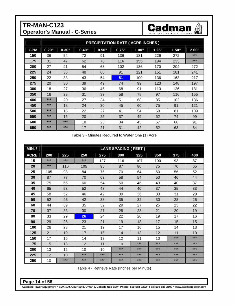
b. From Table 3 on page 14, determine how long it should take to cover one (1) acre, in minutes, by crossing the GPM (from above) by the required application of 0.75”. The shaded block tells you that it should take 81 minutes to cover one (1) acre.
c. From Table 4 on page 14, determine the retrieve rate you need to obtain the desired application of 0.75” by crossing the time required to cover one acre (81 minutes) by the lane spacing (250 feet). The shaded block tells you to set the hose retrieve rate at 26 inches per minute as a starting point.
d. The sprinkler should be set up so that the 250 foot width is covered plus sufficient overlap (beyond the edge of the crop) to provide adequate watering at the edge of the field. Keep in mind that the charts are only a guide. Always check the actual application amount with rain gauges to confirm that the application amount is correct.

TR-MAN-C123 Operator's Manual - C-Series
Page 13 of 56 Cadman Power Equipment ▪ BOX 100, Courtland, Ontario, Canada N0J-1E0 ▪ Phone: 519-688-2222 ▪ Fax: 519-688-2100 ▪ www.cadmanpower.com
Nelson 150 Series Big Gun 27° Trajectory
NOZZLE 0.86 RING 0.97 RING 1.08 RING 1.18 RING 1.26 RING 1.34 RING 1.41 RING PSI GPM DIA. GPM DIA. GPM DIA. GPM DIA. GPM DIA. GPM DIA. GPM DIA. 50 100 245 130 265 165 285 205 300 255 320 300 335 350 350 60 110 260 143 280 182 300 225 315 275 335 330 350 385 365 70 120 270 155 290 197 310 245 330 295 350 355 365 415 380
80 128 280 165 300 210 320 260 340 315 360 380 380 445 395
90 135 290 175 310 223 330 275 350 335 370 405 390 475 405
100 143 300 185 320 235 340 290 360 355 380 425 400 500 415 110 150 310 195 330 247 350 305 370 370 390 445 410 525 425
120 157 315 204 335 258 360 320 380 385 400 465 420 545 435
Table 1 - Nelson 150 Series Big Gun® (Ring)
NOZZLE 0.7 TAPER 0.8 TAPER 0.9 TAPER 1.0 TAPER 1.1 TAPER 1.2 TAPER 1.3 TAPER PSI GPM DIA. GPM DIA. GPM DIA. GPM DIA. GPM DIA. GPM DIA. GPM DIA. 50 100 250 130 270 165 290 205 310 255 330 300 345 350 360 60 110 265 143 285 182 305 225 325 275 345 330 365 385 380 70 120 280 155 300 197 320 245 340 295 360 355 380 415 395 80 128 290 165 310 210 3350 260 355 315 375 380 395 445 410 90 135 300 175 320 223 345 275 365 335 390 405 410 475 425 100 143 310 185 330 235 355 290 375 355 400 425 420 500 440 110 150 320 195 340 247 365 305 385 370 410 445 430 525 450
120 157 330 204 350 258 375 320 395 385 420 465 440 545 460
Table 2 - Nelson 150 Series Big Gun® (Taper)
The diameter of throw is approximately 2% less for the 24® trajectory angle and 5% less for the 21° trajectory angle. The NELSON BIG GUN® performance data has been obtained under ideal test conditions and may be adversely affected by wind, poor hydraulic entrance conditions or other factors. Nelson Irrigation Corporation makes no representation regarding droplet condition, uniformity or application rate.
TR-MAN-C123 Operator's Manual - C-Series
Page 14 of 56 Cadman Power Equipment ▪ BOX 100, Courtland, Ontario, Canada N0J-1E0 ▪ Phone: 519-688-2222 ▪ Fax: 519-688-2100 ▪ www.cadmanpower.com
PRECIPITATION RATE ( ACRE INCHES )
GPM 0.20" 0.30" 0.40" 0.50" 0.75" 1.00" 1.25" 1.50" 2.00" 150 36 54 72 91 136 181 226 272 *** 175 31 47 62 78 116 155 194 233 *** 200 27 41 54 68 102 136 170 204 272 225 24 36 48 60 91 121 151 181 241 250 22 33 43 54 81 109 136 163 217 275 20 30 39 49 74 99 123 148 197 300 18 27 36 45 68 91 113 136 181 350 16 23 31 39 58 78 97 116 155 400 *** 20 27 34 51 68 85 102 136 450 *** 18 24 30 45 60 75 91 121 500 *** 16 22 27 41 54 68 81 109 550 *** 15 20 25 37 49 62 74 99 600 *** *** 18 23 34 45 57 68 91 650 *** *** 17 21 31 42 52 63 84
Table 3 - Minutes Required to Water One (1) Acre
MIN. / LANE SPACING ( FEET ) ACRE 200 225 250 275 300 325 350 375 400
15 *** *** *** 127 116 107 100 93 87 20 *** 116 105 95 87 80 75 70 65 25 105 93 84 76 70 64 60 56 52 30 87 77 70 63 58 54 50 46 44 35 75 66 60 54 50 46 43 40 37 40 65 58 52 48 44 40 37 35 33 45 58 52 46 42 39 36 33 31 29 50 52 46 42 38 35 32 30 28 26 60 44 39 35 32 29 27 25 23 22 70 37 33 30 27 25 23 21 20 19 80 33 29 26 24 22 20 19 17 16 90 29 26 23 21 19 18 17 15 15 100 26 23 21 19 17 16 15 14 13 125 21 19 17 15 14 13 12 11 10 150 17 15 14 13 12 11 10 *** *** 175 15 13 12 11 10 *** *** *** *** 200 13 12 10 10 *** *** *** *** *** 225 12 10 *** *** *** *** *** *** *** 250 10 *** *** *** *** *** *** *** ***
Table 4 - Retrieve Rate (Inches per Minute)
TR-MAN-C123 Operator's Manual - C-Series
Page 15 of 56 Cadman Power Equipment ▪ BOX 100, Courtland, Ontario, Canada N0J-1E0 ▪ Phone: 519-688-2222 ▪ Fax: 519-688-2100 ▪ www.cadmanpower.com
When Applying Liquid Manure Environmental concerns seem to be driving legislative agendas in many agricultural
areas across the continent. Current and pending laws in many agricultural regions of North America are changing the ways in which the agricultural community is expected to manage their liquid animal waste products.
The changes in legislation typically target two main issues; run-off prevention during and after application and soil nutrient loading.
Run-off seems to be the largest concern with nutrient application. Run-off may result from several different factors, most of which are controllable. These factors include; exceeding the soil intake rate; nutrient application on steep grades; high application amounts; leaking mainline fittings and seals; sudden rainfall during or immediately after application; ground frost; etc. Constant watch must be kept and immediate action taken when necessary to prevent run-off from occurring.
Soil nutrient loading depends on many variables. Some of these variables (but certainly not all) are soil type, type of crop being grown in the irrigated area, application timing, nutrient value of the material being applied (nutrient value should be assessed at the time of application as it can change throughout the year), etc.
Soil type will determine the intake rate at which liquid may be applied. Cultivation of the field just prior to application can improve the intake rate of some soils.
Great potential benefit lies in using the nutritional value of the manure being applied to replace some or all of the traditional chemical fertilizer used. Application timing and amount are important considerations. Soil analysis taken prior to planting and during the growth periods of the crop will help determine if there is room for further application amounts to be added prior to crop maturity. A total management plan should include provisions to end the crop season without surplus nutrients left as residual. These excess nutrients typically end up in the ground water supply. Local colleges, universities and agricultural extension services are usually a good source of information. They can usually help you determine an application program that prevents soil nutrient overload due to excess application.
Cadman Power Equipment Limited cannot possibly provide up-to-date recommendations with regard to the legal obligations you must deal with in your particular area. However, as a manufacturer of equipment used in nutrient application (liquid manure, milk house run-off, etc.), we feel it necessary to make you aware that the municipal, regional and state governing bodies in your area may have recently enacted new legislation or revised existing legislation with regard to nutrient handling practices and procedures.
It is your responsibility to make yourself aware of and abide by the current legislation in your area. Please take the time to contact your local agricultural representative to obtain the latest information regarding legal handling and application of manure.

TR-MAN-C123 Operator's Manual - C-Series
Page 16 of 56 Cadman Power Equipment ▪ BOX 100, Courtland, Ontario, Canada N0J-1E0 ▪ Phone: 519-688-2222 ▪ Fax: 519-688-2100 ▪ www.cadmanpower.com
Equipment Set-up Now that you have created a plan you are ready to set up your Cadman C-Series
Traveller in the field. Complete the following instructions to prepare for irrigation.
Step 1 Following your plan, tow the machine to the first section.
It is important to verify that the drive system is engage. Failure to do so can result in equipment damage. If your Cadman Traveller is equipped with the engine drive option ensure prior to moving the engine fuel valve be in the OFF position. Failure to do so can result in equipment damage. For the first use of a new machine or a machine which has been drained prior to storage, start in an area which will allow you to pull out the full length of hose (EXCEPT for one full coil). If you are unable to pull out all of the hose in the current working area, pull out enough hose to reach the base layer. This will allow you to see if the coils of hose in the base layer are stacked tightly together and properly indexed. Low-pressure operation can cause indexing problems. The hose indexing system of your Cadman Traveller is set up to properly index the polyethylene hose onto the hose drum under most operating conditions. However, when operating at very low inlet pressures (110 PSI [7.6 bar] or less), the P.E. (polyethylene) hose can flatten slightly causing the indexing system to appear to be either out of adjustment or not functioning properly. This is probably not the case in this circumstance. It is advisable to increase the inlet pressure at the machine to at least 110 PSI [7.6 bar] to help prevent further hose indexing problems related to low inlet pressures.

TR-MAN-C123 Operator's Manual - C-Series
Page 17 of 56 Cadman Power Equipment ▪ BOX 100, Courtland, Ontario, Canada N0J-1E0 ▪ Phone: 519-688-2222 ▪ Fax: 519-688-2100 ▪ www.cadmanpower.com
Step 2 Park the traveller on the head land (lane way) at right angles to the row to be
irrigated. Keep the machine on firm and level ground. Use the tongue jack to level the frame prior to machine operation.
Figure 10 - Work on firm and level ground (image exaggerated) img-00505
Step 3 Release the turntable lock and rotate the upper frame to the desired operating
position and re-engage the turntable lock.
Figure 11 - Correct Upper Frame Position img-00240
The upper frame position MUST allow the hose to pull out straight from the machine. Adjust the upper frame position if necessary to insure proper unreeling of the hose. Failure to have the correct upper frame position will result in equipment damage.

TR-MAN-C123 Operator's Manual - C-Series
Page 18 of 56 Cadman Power Equipment ▪ BOX 100, Courtland, Ontario, Canada N0J-1E0 ▪ Phone: 519-688-2222 ▪ Fax: 519-688-2100 ▪ www.cadmanpower.com
Step 4 Stabilize your machine by fully engaging the stabilizers.
Never operate this machine without BOTH (2) stabilizers engaged. Failure to engage both stabilizers will result in serious equipment damage and potential for injuries to you and/or spectators. If a rear pull is required, provisions to leave the tractor attached to the tongue of the machine are necessary. The tractor is to be in gear and the parking brake engaged. This provides extra anchoring in addition to the stabilizer legs during the retrieve cycle.
Step 5 Turn the iWater™ Control system to the "ON" position.
Figure 12 - Turn Power ON img-00500
It is important to have the computer "ON" before you pull out the hose. During hose pullout, the hose is measured. Failure to have the computer on during pullout will result in loss of advanced options (i.e. sprinkler kit, beacon light etc.). If you have forgotten this by mistake, see instruction on how to correct this on page 47.

TR-MAN-C123 Operator's Manual - C-Series
Page 19 of 56 Cadman Power Equipment ▪ BOX 100, Courtland, Ontario, Canada N0J-1E0 ▪ Phone: 519-688-2222 ▪ Fax: 519-688-2100 ▪ www.cadmanpower.com
Step 6 Shift the transmission lever to the disengaged position.
Figure 13 - Disengage Transmission img-00501
Step 7 Adjust the brake handle position so that a slight amount of brake tension is applied.
This tension should be enough to control the hose drum and prevent loosening of the hose on the drum when the tractor stops pulling the hose.
Figure 14 - Engage Brake img-00502

TR-MAN-C123 Operator's Manual - C-Series
Page 20 of 56 Cadman Power Equipment ▪ BOX 100, Courtland, Ontario, Canada N0J-1E0 ▪ Phone: 519-688-2222 ▪ Fax: 519-688-2100 ▪ www.cadmanpower.com
Step 8 Set the sprinkler cart track width as wide as possible to maximize stability. With sprinkler flows exceeding 240 gallons [910 liters] per minute, or when operating
on uneven terrain, additional weight MUST be added to maintain sprinkler cart stability and help prevent sprinkler cart upset.
Figure 15 - Sprinkler Cart Weight img-00258-A
Additional weight may be gained by “loading” the sprinkler cart tires and/or using tractor front end weights as required.
Step 9 Move the tractor from the front of the machine, position it behind the sprinkler cart
and raise the tractor drawbar until it can engage the sprinkler cart tow hook.

TR-MAN-C123 Operator's Manual - C-Series
Page 21 of 56 Cadman Power Equipment ▪ BOX 100, Courtland, Ontario, Canada N0J-1E0 ▪ Phone: 519-688-2222 ▪ Fax: 519-688-2100 ▪ www.cadmanpower.com
Step 10 Tow the sprinkler cart to the start point of irrigation. Always leave as a minimum one
(1) wrap of hose on the drum. When pulling the hose out keep it straight.
Figure 16 - Pull Out Hose Straight img-00244
DO NOT exceed 3 mph [5 km/h] while pulling out the hose. DO NOT stop suddenly at the end of your travel lane. Slow gradually when nearing the end of the pull. Keep spectators away from the machine while pulling out the hose. Failure to follow these instructions may result in serious equipment damage and potential for injuries to you and/or spectators.
Step 11 Verify the sprinkler set up is correct. Install the correct nozzle and tighten the nozzle
cone. Also at this time, set the part circle stops on the sprinkler. The sprinkler should be set behind the cart so that the travel path remains dry until the cart passes.
Figure 17 - Correct Spray Setting img-00201
TR-MAN-C123 Operator's Manual - C-Series
Page 22 of 56 Cadman Power Equipment ▪ BOX 100, Courtland, Ontario, Canada N0J-1E0 ▪ Phone: 519-688-2222 ▪ Fax: 519-688-2100 ▪ www.cadmanpower.com
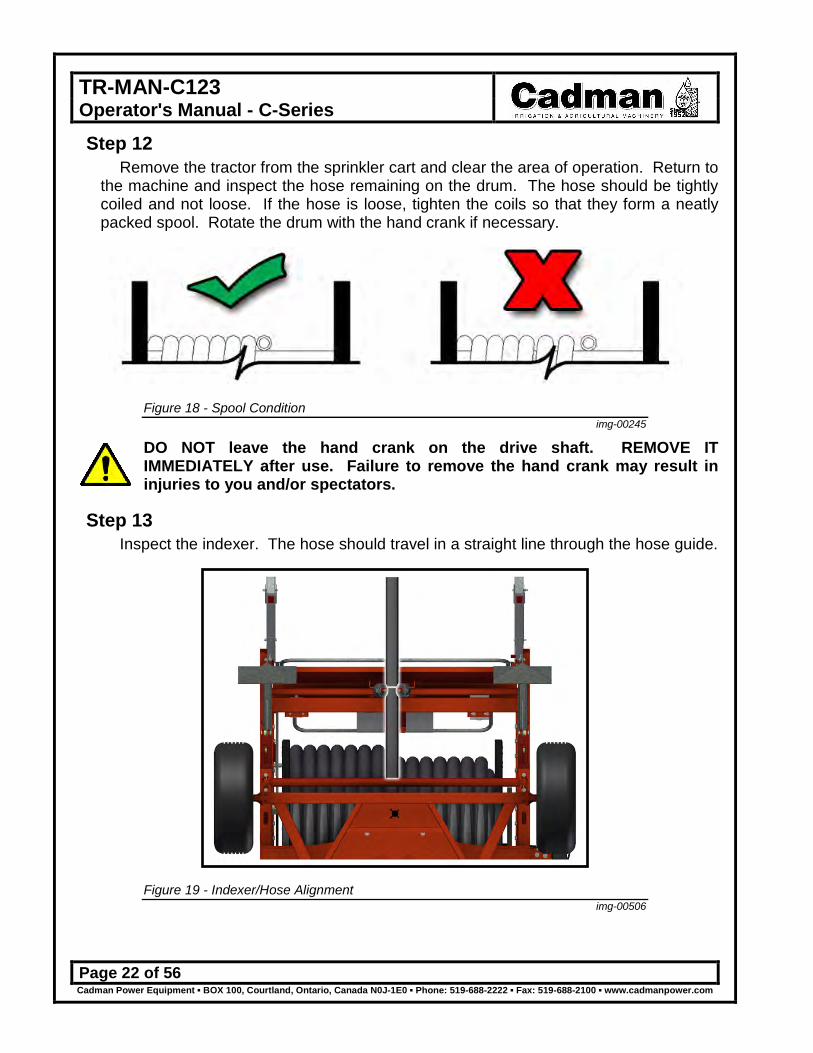
Step 12 Remove the tractor from the sprinkler cart and clear the area of operation. Return to
the machine and inspect the hose remaining on the drum. The hose should be tightly coiled and not loose. If the hose is loose, tighten the coils so that they form a neatly packed spool. Rotate the drum with the hand crank if necessary.
Figure 18 - Spool Condition img-00245
DO NOT leave the hand crank on the drive shaft. REMOVE IT IMMEDIATELY after use. Failure to remove the hand crank may result in injuries to you and/or spectators.
Step 13 Inspect the indexer. The hose should travel in a straight line through the hose guide.
Figure 19 - Indexer/Hose Alignment img-00506

TR-MAN-C123 Operator's Manual - C-Series
Page 23 of 56 Cadman Power Equipment ▪ BOX 100, Courtland, Ontario, Canada N0J-1E0 ▪ Phone: 519-688-2222 ▪ Fax: 519-688-2100 ▪ www.cadmanpower.com
Step 14 Adjust the brake handle to the full “ON” position after ensuring that the hose is tight.
Figure 20 - Tighten Brake img-00502
Step 15 GRADUAL pressurization of the system may now begin. Keep the pressure low
(under 50 PSI [3.5 bar]) until ALL the air is purged from the system and a steady stream is flowing from the sprinkler nozzle. AFTER all the air is purged from the system, pressure may be slowly raised to a maximum of 150 PSI [10.4 bar] at the inlet of the machine.
Ideally, operating pressures at the inlet will be between 120 PSI [8.3 bar] and 150 PSI [10.4 bar]. This will allow sprinkler pressures ranging from approximately 50 PSI [3.5 bar] to 110 PSI [7.6 bar] (depending on nozzle size, hose size and length). Assuming a nozzle is been selected properly based on the pressure and flow volume available, proper droplet sizing and proper sprinkler action, an even and uniform watering pattern will result. The irrigation sprinkler projects a large volume of pressurized water. Contact with the sprinkler’s discharge will result in injury. Avoid the area where irrigation is taking place.
Step 16 Check the mainline and inlet elbow connections.

TR-MAN-C123 Operator's Manual - C-Series
Page 24 of 56 Cadman Power Equipment ▪ BOX 100, Courtland, Ontario, Canada N0J-1E0 ▪ Phone: 519-688-2222 ▪ Fax: 519-688-2100 ▪ www.cadmanpower.com
Step 17 Remove all braking force. The brake handle must be completely loose.
Figure 21 - Remove Brake Tension img-00503
Failure to disengage the brake fully will cause heat build up and can cause equipment damage.
Step 18 Engage the transmission to prepare for pull.
Figure 22 - Engage Transmission img-00504
Step 17 Set up a pull with the iWater™ Controller using the following instructions.

TR-MAN-C123 Operator's Manual - C-Series
Page 25 of 56 Cadman Power Equipment ▪ BOX 100, Courtland, Ontario, Canada N0J-1E0 ▪ Phone: 519-688-2222 ▪ Fax: 519-688-2100 ▪ www.cadmanpower.com
iWater™ Controller Instructions The iWater™ Controller begins with an initialization screen. This takes a few
moments to set the computer. This screen shows the current software version in the lower right corner. You may be required to include this information during any computer related service calls.
Figure 23 - Initialization Screen img-00514
Once the computer has initialized you start at the main menu. This screen gives the option of which menu you would like to choose. It also gives current information such as time, battery charge level, signal strength and current menu selected.
Figure 24 - Screen Layout img-00515
TR-MAN-C123 Operator's Manual - C-Series
Page 26 of 56 Cadman Power Equipment ▪ BOX 100, Courtland, Ontario, Canada N0J-1E0 ▪ Phone: 519-688-2222 ▪ Fax: 519-688-2100 ▪ www.cadmanpower.com
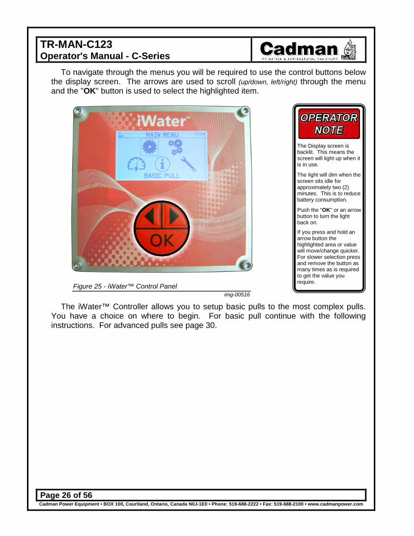
To navigate through the menus you will be required to use the control buttons below the display screen. The arrows are used to scroll (up/down, left/right) through the menu and the "OK" button is used to select the highlighted item.
Figure 25 - iWater™ Control Panel img-00516
The iWater™ Controller allows you to setup basic pulls to the most complex pulls. You have a choice on where to begin. For basic pull continue with the following instructions. For advanced pulls see page 30.
The Display screen is backlit. This means the screen will light up when it is in use.
The light will dim when the screen sits idle for approximately two (2) minutes. This is to reduce battery consumption.
Push the "OK" or an arrow button to turn the light back on.
If you press and hold an arrow button the highlighted area or value will move/change quicker. For slower selection press and remove the button as many times as is required to get the value you require.

TR-MAN-C123 Operator's Manual - C-Series
Page 27 of 56 Cadman Power Equipment ▪ BOX 100, Courtland, Ontario, Canada N0J-1E0 ▪ Phone: 519-688-2222 ▪ Fax: 519-688-2100 ▪ www.cadmanpower.com
Basic Pull As the title states this option is for an irrigation pull that is straight forward with no
changes required from start to finish.
Step 1 Choose the screen option Basic Pull. Select the "OK" button.
Figure 26 - Main Menu Screen img-00517
Step 2 The Basic Pull menu has simple settings. To change any of the default settings
please see the Control Panel section of this manual found on page 39. The first menu item is to choose the retrieve rate.
Figure 27 - Basic Pull Menu img-00518
TR-MAN-C123 Operator's Manual - C-Series
Page 28 of 56 Cadman Power Equipment ▪ BOX 100, Courtland, Ontario, Canada N0J-1E0 ▪ Phone: 519-688-2222 ▪ Fax: 519-688-2100 ▪ www.cadmanpower.com
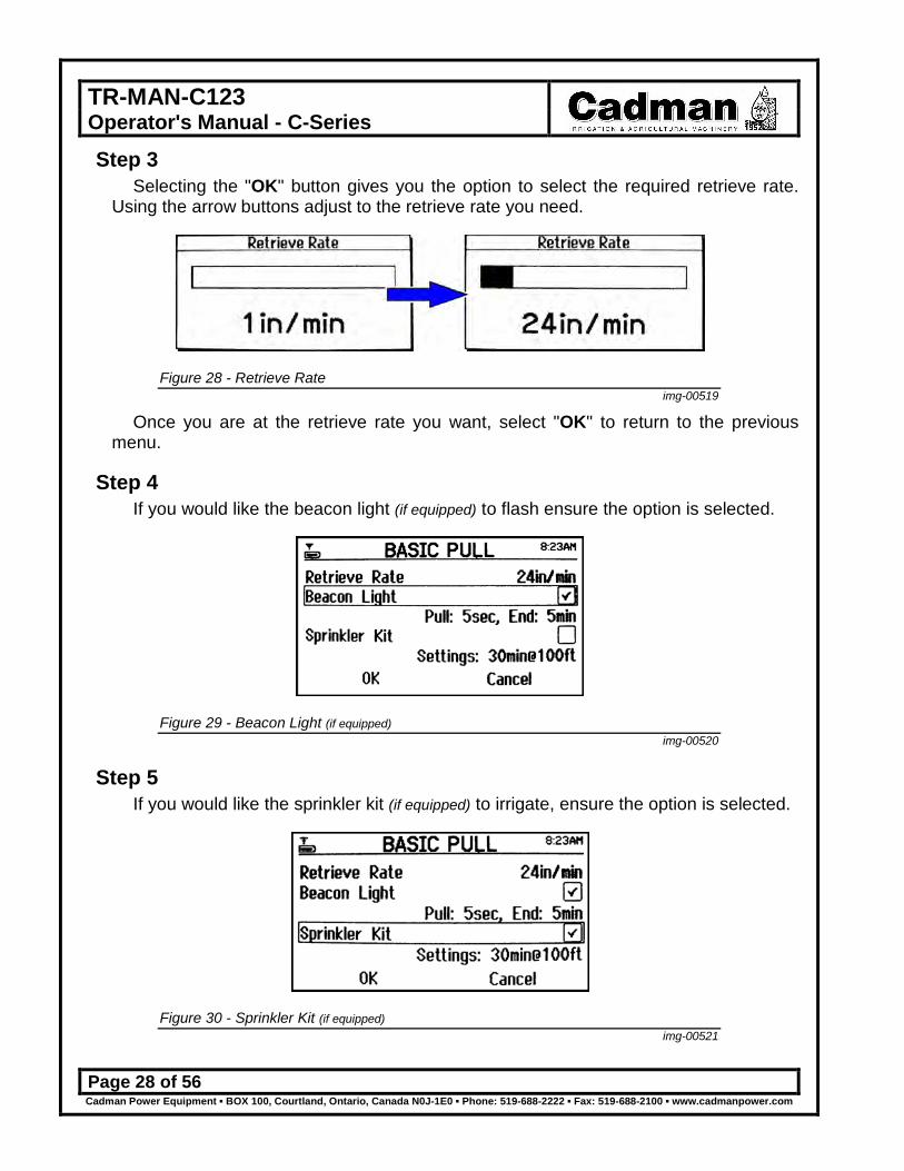
Step 3 Selecting the "OK" button gives you the option to select the required retrieve rate.
Using the arrow buttons adjust to the retrieve rate you need.
Figure 28 - Retrieve Rate img-00519
Once you are at the retrieve rate you want, select "OK" to return to the previous menu.
Step 4 If you would like the beacon light (if equipped) to flash ensure the option is selected.
Figure 29 - Beacon Light (if equipped) img-00520
Step 5 If you would like the sprinkler kit (if equipped) to irrigate, ensure the option is selected.
Figure 30 - Sprinkler Kit (if equipped) img-00521

TR-MAN-C123 Operator's Manual - C-Series
Page 29 of 56 Cadman Power Equipment ▪ BOX 100, Courtland, Ontario, Canada N0J-1E0 ▪ Phone: 519-688-2222 ▪ Fax: 519-688-2100 ▪ www.cadmanpower.com
Step 6 Once the options have been chosen, select the "OK" at the bottom of the screen.
This will start the emergency stop and shut off system test. You will be required to actuate the shut off bar and return it to normal position. You will also be required to push in and pull out the emergency button. This will allow you to begin your pull.
Figure 31 - Emergency Stop / Shut off System Test img-00522
Step 7 Once the "Begin Pull" has been selected you will be brought to the gauge panel
screen. This screen will provide you with a predicted finish time. It will also display how much hose is pulled out and the current retrieve rate.
Figure 32 - Gauge Panel img-00523

TR-MAN-C123 Operator's Manual - C-Series
Page 30 of 56 Cadman Power Equipment ▪ BOX 100, Courtland, Ontario, Canada N0J-1E0 ▪ Phone: 519-688-2222 ▪ Fax: 519-688-2100 ▪ www.cadmanpower.com
Advanced Pull This section allows for a more customized pull setup. This gives you more control
on how the water is applied to your fields. You can also recall saved pulls from previous setups. The following instructions will help you create your own custom pull.
Step 1 Choose the screen option Advanced Pull. Select the "OK" button.
Figure 33 - Advanced Pull img-00524
Step 2 This screen gives you the option of recalling a saved pull or creating a new pull. For
the first time using advanced pull you will be required to select "Create a Pull". To recall a saved pull select the "Recall a Pull" menu option. Choose a file listed
and all setting will be changed to what was saved in the pull file.
Figure 34 - Create a Pull img-00525

TR-MAN-C123 Operator's Manual - C-Series
Page 31 of 56 Cadman Power Equipment ▪ BOX 100, Courtland, Ontario, Canada N0J-1E0 ▪ Phone: 519-688-2222 ▪ Fax: 519-688-2100 ▪ www.cadmanpower.com
Step 3 With advanced pull many options become available to customize your irrigation pull.
Delayed Start ○ Initial Pause Retrieve Rate Programmed Events
Auxiliary Control #1 ○ Auxiliary Control #2 ○ Final Pause ♦ Beacon Light ○
Sprinkler Kit ○ Wireless Communication ♦ Mobile Phone ♦
○ requires optional equipment / ♦ late availability
Figure 35 - Advanced Pull Options img-00526
Delayed Start ○ This setting allows you to start your pull at a later time. This requires optional
equipment. For further information please contact Cadman Power Equipment Limited or your local dealer.
Using the arrow keys adjust the time to the desired start time. Select "OK" once you have reached the chosen time. Select "Enabled" to enable this option.
Figure 36 - Delayed Start img-00527
When using this option with the engine drive option, it is important to have the engine running. Failure to have the engine running will result in a system shutdown at the chosen start time. This will also result in a great deal of water expelled in one localized area.

TR-MAN-C123 Operator's Manual - C-Series
Page 32 of 56 Cadman Power Equipment ▪ BOX 100, Courtland, Ontario, Canada N0J-1E0 ▪ Phone: 519-688-2222 ▪ Fax: 519-688-2100 ▪ www.cadmanpower.com
Initial Pause This setting allows you to delay the start of the pull while irrigating the field. Using
the arrow keys adjust the delay to the desired amount of time. Select "OK" to continue. To disable this feature use the left arrow key to reduce the time until "OFF" appears.
Figure 37 - Initial Pause img-00528
Retrieval Rate In this area you are able to choose the type of retrieval. This allows for greater
control of the irrigation cycle.
Figure 38 - Retrieve Rate Types img-00529

TR-MAN-C123 Operator's Manual - C-Series
Page 33 of 56 Cadman Power Equipment ▪ BOX 100, Courtland, Ontario, Canada N0J-1E0 ▪ Phone: 519-688-2222 ▪ Fax: 519-688-2100 ▪ www.cadmanpower.com
Speed Set: Units per minute. This allows you to set the pull based on the rate of speed (i.e. 24 in/min). Pull Duration: Duration in Hours and Minutes. This allows you to set the pull to be completed within a given time (i.e. 11 hours 30 minutes). Finish Time: Completes pull by a set time. You can choose to complete the pull at a specific time. This time must be adequate for the drive system to be able to maintain the required speeds (i.e. starting at 8:00 am have the pull completed by 8:30 pm). Application Depth: Applies the necessary amount of water to reach the requested depth based on sprinkler pressure. This setting also takes into consideration the installed sprinkler and nozzle size set in the Control Panel under the sprinkler section. For instructions on how to set this see page 44.
Programmed Events This area allows you to control the application rate in given areas of the field. For
example if your field has hills and valleys you are able to speed up or slow down the pull speed. Typically valley portions of the pull should have the retrieve rate sped up. For hill portions of the pull the retrieve rate should be slowed down. This will allow for different coverage of irrigation water based on soil types.
Figure 39 - Suggested Speed Changes img-00530
Figure 40 - Program Events img-00531

TR-MAN-C123 Operator's Manual - C-Series
Page 34 of 56 Cadman Power Equipment ▪ BOX 100, Courtland, Ontario, Canada N0J-1E0 ▪ Phone: 519-688-2222 ▪ Fax: 519-688-2100 ▪ www.cadmanpower.com
Event Number: This lists the current event being programmed. The iWater™ Control System allows for up to eight (8) unique events. Start: This tells when this event should begin the change. This dimension is measured from the traveller to the sprinkler position in the field. Rate: This is what the new retrieve rate will be during the displayed event. Finish This tells when this event should return to the default retrieve rate. This dimension is measured from the traveller to the sprinkler position in the field. OK This programs the current event number and returns to previous screen. MORE This allows you to program additional events to a maximum of eight (8) individual events.
Use the control buttons to adjust to the required values. If an error has been made or the event is no longer required you must restart the programmed event change screen. To do this you select "OK" on the screen then press "OK" button. This will return to the Advanced Pull screen. Select the Programmed Events again and choose the event to be modified or removed. Select the value to change.
If you want to remove an event you must reduce the Start value until it displays "Delete Event" by pressing the left arrow, then select "OK".
Auxiliary Control #1 & #2 ○ If you would like to control auxiliary components you would use this area to setup the
duration time and distance for actuation. These control relays work either by opening or by closing the circuit. You can adjust how these relays work in the Control Panel section labeled "Auxiliary Relay" found on page 43.
Figure 41 - Auxiliary Relays img-00532
TR-MAN-C123 Operator's Manual - C-Series
Page 35 of 56 Cadman Power Equipment ▪ BOX 100, Courtland, Ontario, Canada N0J-1E0 ▪ Phone: 519-688-2222 ▪ Fax: 519-688-2100 ▪ www.cadmanpower.com
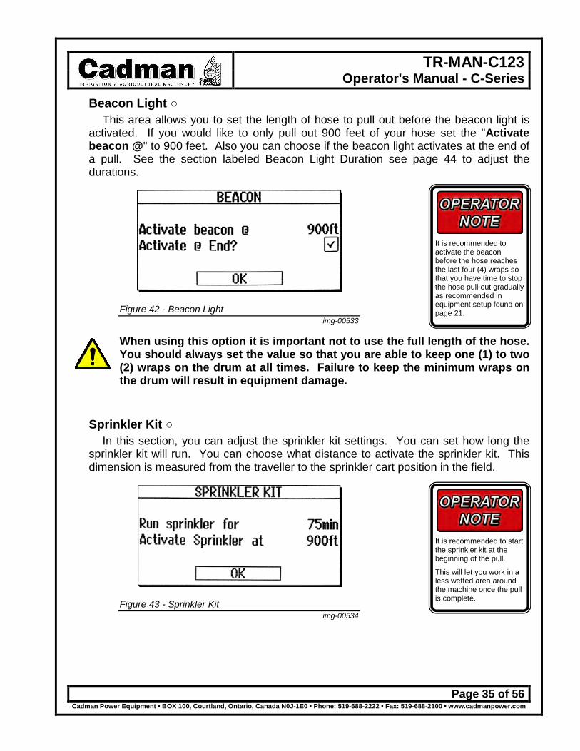
Beacon Light ○ This area allows you to set the length of hose to pull out before the beacon light is
activated. If you would like to only pull out 900 feet of your hose set the "Activate beacon @" to 900 feet. Also you can choose if the beacon light activates at the end of a pull. See the section labeled Beacon Light Duration see page 44 to adjust the durations.
Figure 42 - Beacon Light img-00533
When using this option it is important not to use the full length of the hose. You should always set the value so that you are able to keep one (1) to two (2) wraps on the drum at all times. Failure to keep the minimum wraps on the drum will result in equipment damage.
Sprinkler Kit ○ In this section, you can adjust the sprinkler kit settings. You can set how long the
sprinkler kit will run. You can choose what distance to activate the sprinkler kit. This dimension is measured from the traveller to the sprinkler cart position in the field.
Figure 43 - Sprinkler Kit img-00534
It is recommended to start the sprinkler kit at the beginning of the pull.
This will let you work in a less wetted area around the machine once the pull is complete.
It is recommended to activate the beacon before the hose reaches the last four (4) wraps so that you have time to stop the hose pull out gradually as recommended in equipment setup found on page 21.

TR-MAN-C123 Operator's Manual - C-Series
Page 36 of 56 Cadman Power Equipment ▪ BOX 100, Courtland, Ontario, Canada N0J-1E0 ▪ Phone: 519-688-2222 ▪ Fax: 519-688-2100 ▪ www.cadmanpower.com
Step 4 Now that you have completed setting up the various advance pull options is time to
complete the configuration. Select the "OK" button to continue. A pop up screen will appear asking if you would like to save the pull or continue.
If you continue, the settings you have modified will not record. Next time you use the machine you will be required to set up the same information.
Choosing save allows you to record all the setting for the next time you use the machine. Cadman Power Equipment Limited recommends that you save the settings to speed up the setup process.
Figure 44 - Save Pull img-00535
Highlight "Save" then select the "OK" button to continue.
Step 5 Choose one of the available memory slots to store your advanced pull.
Figure 45 - Memory Slot img-00536

TR-MAN-C123 Operator's Manual - C-Series
Page 37 of 56 Cadman Power Equipment ▪ BOX 100, Courtland, Ontario, Canada N0J-1E0 ▪ Phone: 519-688-2222 ▪ Fax: 519-688-2100 ▪ www.cadmanpower.com
Step 6 Using the arrow keys adjust the description. After each letter is selected press the
"OK" button once. Once you have the name chosen an arrow (↵) will appear. If you select the "OK" button it will give the choice of either OK or Cancel.
OK will save the file for future use. Cancel will exit the save area.
Figure 46 - Pull Identification img-00537
Step 7 Once you have saved the file, select the "OK" at the bottom of the screen. This will
start the emergency stop and shut off system test. You will be required to actuate the shut off bar and return it to normal position. You will also be required to push in and pull out the emergency button. This will allow you to begin your pull.
Figure 47 - Emergency Stop / Shut off System Test img-00538
It is a good idea to give the Pull IDs names that are relative to your field plan layout.
This will speed the setup process.

TR-MAN-C123 Operator's Manual - C-Series
Page 38 of 56 Cadman Power Equipment ▪ BOX 100, Courtland, Ontario, Canada N0J-1E0 ▪ Phone: 519-688-2222 ▪ Fax: 519-688-2100 ▪ www.cadmanpower.com
Step 8 Once the "Begin Pull" has been selected you will be brought to the gauge panel
screen. This screen will provide you with a predicted finish time. It will also display how much hose is pulled out and the current retrieve rate.
Figure 48 - Gauge Panel img-00523
TR-MAN-C123 Operator's Manual - C-Series
Page 39 of 56 Cadman Power Equipment ▪ BOX 100, Courtland, Ontario, Canada N0J-1E0 ▪ Phone: 519-688-2222 ▪ Fax: 519-688-2100 ▪ www.cadmanpower.com
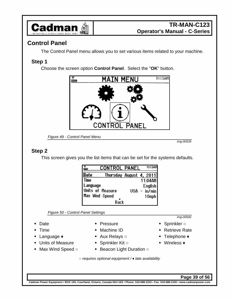
Control Panel The Control Panel menu allows you to set various items related to your machine.
Step 1 Choose the screen option Control Panel. Select the "OK" button.
Figure 49 - Control Panel Menu img-00539
Step 2 This screen gives you the list items that can be set for the systems defaults.
Figure 50 - Control Panel Settings img-00540
Date Time Language ♦ Units of Measure Max Wind Speed ○
Pressure Machine ID Aux Relays ○ Sprinkler Kit ○ Beacon Light Duration ○
Sprinkler ○ Retrieve Rate Telephone ♦ Wireless ♦
○ requires optional equipment / ♦ late availability

TR-MAN-C123 Operator's Manual - C-Series
Page 40 of 56 Cadman Power Equipment ▪ BOX 100, Courtland, Ontario, Canada N0J-1E0 ▪ Phone: 519-688-2222 ▪ Fax: 519-688-2100 ▪ www.cadmanpower.com
Date This date should already be factory preset, however if there is a change required
use the arrow keys to adjust the date. Once the correct date is shown select the "OK" button. This will set the system date.
Figure 51 - Change Date Screen img-00541
Time This time should already be factory preset, however if there is a change required use
the arrow keys to adjust the time. Once the correct date is shown select the "OK" button. This will set the system time.
You can also change the format from 12 to 24 hours. Highlight the format and use the arrow button to adjust the setting.
Figure 52 - Change Time Screen img-00542

TR-MAN-C123 Operator's Manual - C-Series
Page 41 of 56 Cadman Power Equipment ▪ BOX 100, Courtland, Ontario, Canada N0J-1E0 ▪ Phone: 519-688-2222 ▪ Fax: 519-688-2100 ▪ www.cadmanpower.com
Units of Measure The factory setting for Units of Measure is "USA - in.min". Select the format that is
preferred then select "OK".
Figure 53 - Units of Measure img-00543
Maximum Wind Speed ○ This setting requires that you have the wind sensor option installed. You are able to
stop the irrigation cycle if the wind exceeds the set speed. Once the wind speed reduces to below the maximum setting irrigation will continue.
Figure 54 - Set Maximum Wind Speed img-00544

TR-MAN-C123 Operator's Manual - C-Series
Page 42 of 56 Cadman Power Equipment ▪ BOX 100, Courtland, Ontario, Canada N0J-1E0 ▪ Phone: 519-688-2222 ▪ Fax: 519-688-2100 ▪ www.cadmanpower.com
Pressure A minimum and maximum pressure setting can be set to better control the irrigation
application. If the pressure is outside the set range the pull will be stopped. Once the pressure returns to the set range the pull will restart.
Figure 55 - Pressure Settings img-00545
Machine ID Each machine can be set with unique machine identification. With unique
identification your field planning can be better controlled. Your plan can include the ID with the pull program settings. This will help with consistent irrigation setups.
Figure 56 - Machine Identification img-00546

TR-MAN-C123 Operator's Manual - C-Series
Page 43 of 56 Cadman Power Equipment ▪ BOX 100, Courtland, Ontario, Canada N0J-1E0 ▪ Phone: 519-688-2222 ▪ Fax: 519-688-2100 ▪ www.cadmanpower.com
Auxiliary Relays ○ You can set how the auxiliary relays operated. They can be set as normally
open (N.O.) or normally closed (N.C.). This setting will be dependent on the unit you plan on controlling. For further information please contact Cadman Power Equipment Limited or your local dealer.
Figure 57 - Auxiliary Relay Settings img-00547
Sprinkler Kit ○ As in the advanced pull section, you can set how long the sprinkler kit will run. You
can choose what distance to activate the sprinkler kit. This dimension is measured from the traveller to the sprinkler cart position in the field. This will be the default setting for the machine during a basic pull setup.
Figure 58 - Sprinkler Kit img-00534
It is recommended to start the sprinkler kit at the beginning of the pull.
This will let you work in a less wetted area around the machine.
TR-MAN-C123 Operator's Manual - C-Series
Page 44 of 56 Cadman Power Equipment ▪ BOX 100, Courtland, Ontario, Canada N0J-1E0 ▪ Phone: 519-688-2222 ▪ Fax: 519-688-2100 ▪ www.cadmanpower.com
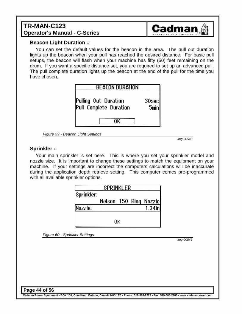
Beacon Light Duration ○ You can set the default values for the beacon in the area. The pull out duration
lights up the beacon when your pull has reached the desired distance. For basic pull setups, the beacon will flash when your machine has fifty (50) feet remaining on the drum. If you want a specific distance set, you are required to set up an advanced pull. The pull complete duration lights up the beacon at the end of the pull for the time you have chosen.
Figure 59 - Beacon Light Settings img-00548
Sprinkler ○ Your main sprinkler is set here. This is where you set your sprinkler model and
nozzle size. It is important to change these settings to match the equipment on your machine. If your settings are incorrect the computers calculations will be inaccurate during the application depth retrieve setting. This computer comes pre-programmed with all available sprinkler options.
Figure 60 - Sprinkler Settings img-00549

TR-MAN-C123 Operator's Manual - C-Series
Page 45 of 56 Cadman Power Equipment ▪ BOX 100, Courtland, Ontario, Canada N0J-1E0 ▪ Phone: 519-688-2222 ▪ Fax: 519-688-2100 ▪ www.cadmanpower.com
Retrieval Rate In this area you are able to choose the type of retrieval. This allows for greater
control of the irrigation cycle. This will be the default setting for the basic pull.
Figure 61 - Retrieve Rate Types img-00529
Speed Set: Units per minute. This allows you to set the pull based on the rate of speed (i.e. 24 in/min). Pull Duration: Duration in Hours and Minutes. This allows you to set the pull to be completed within a given time (i.e. 11 hours 30 minutes). Finish Time: Completes pull by a set time. You can choose to complete the pull at a specific time. This time must be adequate for the drive system to be able to maintain the required speeds (i.e. starting at 8:00 am have the pull completed by 8:30 pm). Application Depth: Applies the necessary amount of water to reach the requested depth based on sprinkler pressure. This setting also takes into consideration the installed sprinkler and nozzle size set in the Control Panel under the sprinkler section. For instructions on how to set this see page 44.

TR-MAN-C123 Operator's Manual - C-Series
Page 46 of 56 Cadman Power Equipment ▪ BOX 100, Courtland, Ontario, Canada N0J-1E0 ▪ Phone: 519-688-2222 ▪ Fax: 519-688-2100 ▪ www.cadmanpower.com
Service Panel This area is primarily meant for the Cadman Power Equipment Limited service team.
You have been given access to a few items.
Step 1 Choose the screen option Service. Select the "OK" button.
Figure 62 - Service img-00550
Step 2 This screen allows you to view the number of hours your machine has been in
service. The hours recorded are the actual run time of the machine.
Figure 63 - Service Panel img-00551

TR-MAN-C123 Operator's Manual - C-Series
Page 47 of 56 Cadman Power Equipment ▪ BOX 100, Courtland, Ontario, Canada N0J-1E0 ▪ Phone: 519-688-2222 ▪ Fax: 519-688-2100 ▪ www.cadmanpower.com
Step 3 The only area in which you can change is the "Set Distance" portion of the Service
Panel. The other items are for the Cadman Power Equipment Limited service team and should not be modified.
The set distance portion of the Service Panel is primarily meant to set the hose distance if the computer was turned off during pull out. This is easily fixed by modifying the value using the set distance tool. You will need to know how much hose has been pulled out. To determine this you must measure the hose length from the shut off bar to the sprinkler cart shut down marker flag. Select the menu option "Set Distance".
Figure 64 - Set Distance img-00552
Set the length of hose that has been pulled out. Then select the "OK" button. This will update the computer to the proper length.
Figure 65 - Set Distance Adjustment Screen img-00553
You can still pull in the hose without resetting the hose length; however you will lose the hose speed compensation. You will also not be able to use any advance pull features. Once the sprinkler cart marker flag shuts the machine down the hose length will reset to zero (0).
If your pull is dependent on programmed features, set the hose length. Failure to reset the hose length will cause missed features of the pull. This will reduce the planned irrigations accuracy.

TR-MAN-C123 Operator's Manual - C-Series
Page 48 of 56 Cadman Power Equipment ▪ BOX 100, Courtland, Ontario, Canada N0J-1E0 ▪ Phone: 519-688-2222 ▪ Fax: 519-688-2100 ▪ www.cadmanpower.com
Engine Drive Option Once the iWater™ has been set up it is time to start the engine.
Step 1 Check the engine oil and fuel levels.
Figure 66 - Check Oil img-00557
Step 2 Open fuel valve on motor. Pull recoil to start engine. Set engine throttle.
Figure 67 - Start Engine img-00554
If after several attempts the engine fails to start, check to see if the Emergency Stop button is in the OFF position. In addition, check the shut off bar, check to see if there are any triggered stop switches. The engine will not start if the switches are in the triggered or off positions. When setting the engine throttle, choose a setting that will not be underpowered for the drive system. The operator must verify the engine throttled after five minutes of pulling. This will ensure a proper irrigation cycle.

TR-MAN-C123 Operator's Manual - C-Series
Page 49 of 56 Cadman Power Equipment ▪ BOX 100, Courtland, Ontario, Canada N0J-1E0 ▪ Phone: 519-688-2222 ▪ Fax: 519-688-2100 ▪ www.cadmanpower.com
Step 3 Once the engine is running, select "Begin Pull" then select the "OK" button on the
iWater™ controller.
Figure 68 - Begin Pull img-00555
Step 4 After the pull is complete close the fuel valve of the engine.
Figure 69 - Shut Fuel Valve img-00556
You are required to shut the fuel valve after every pull. Never transport the machine without verifying the fuel valve is closed. Failure to shut the fuel valve WILL result in equipment damage.

TR-MAN-C123 Operator's Manual - C-Series
Page 50 of 56 Cadman Power Equipment ▪ BOX 100, Courtland, Ontario, Canada N0J-1E0 ▪ Phone: 519-688-2222 ▪ Fax: 519-688-2100 ▪ www.cadmanpower.com
Turbine Drive Option Once the iWater™ has been set up it is time begin the pull.
Step 1 The Cadman Turbine has been designed for ease of use. Select "OK" to begin the
pull. There are no adjustments made by the operator.
Figure 70 - Begin Pull (Turbine) img-00560
Step 2 Verify that the turbine is producing enough power to maintain the current pull.

TR-MAN-C123 Operator's Manual - C-Series
Page 51 of 56 Cadman Power Equipment ▪ BOX 100, Courtland, Ontario, Canada N0J-1E0 ▪ Phone: 519-688-2222 ▪ Fax: 519-688-2100 ▪ www.cadmanpower.com
Required Maintenance Prevention of mechanical failure is the goal of any good maintenance schedule. The
secret to preventing unwanted down time is to adhere to a maintenance schedule suited to the way you use the equipment. Your maintenance schedule should include the following minimum requirements:
Only complete maintenance when the machine is shutdown and is in a non-loaded condition. This means that no pumping of fluid through the reel and release all mechanical and hydraulic tension from the hose rewind system.
Each Use Maintenance Item Figure Procedure
Visually inspect equipment
Walk around the unit and inspect for loose, missing or damaged items. Check the condition of tongue pivot pin, chain and connecting links. Replace missing or damaged items and tighten loosened items.
Maintain the tire pressure posted on tire sidewall
Using a tire pressure gauge, check the pressure of each tire and add or remove air to achieve the desired pressure.
DO NOT LOWER TIRE PRESSURE BELOW THE RECOMMENDED LEVEL. A lower pressure than the recommended pressure will result in the tire separating from the rim. DO NOT OVER INFLATE TIRE. Pressure higher than recommended will result in wheel failure which could result in serious injury and/or death.
Tighten all wheel bolts
img-00224
Before moving the unit, verify that the wheel bolts are tight. When tightening the lug nuts use the star pattern with your torque wrench set at 150 ft/lbs [203 N.m].
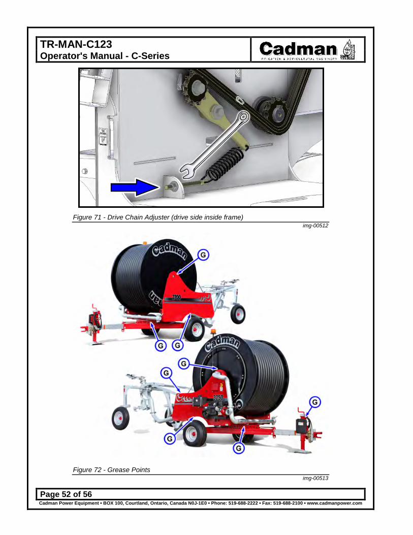
Adjust, if necessary, the alignment and tension of the
drive chain
Figure 71 The drive chain (around the drum) is properly tensioned when it has no visible slack and is seating properly onto the drive sprocket when the drum rotates. Adjustments are made by turning the locknut (3/4” wrench) on the spring adjustment rod.
Lubricate all grease fittings Figure 72 Using a grease gun, lubricate all grease fittings with an appropriate amount of acceptable grease. (See Lubricants)
Table 5 - Required Maintenance - Each Use
TR-MAN-C123 Operator's Manual - C-Series
Page 52 of 56 Cadman Power Equipment ▪ BOX 100, Courtland, Ontario, Canada N0J-1E0 ▪ Phone: 519-688-2222 ▪ Fax: 519-688-2100 ▪ www.cadmanpower.com
Figure 71 - Drive Chain Adjuster (drive side inside frame)
img-00512
Figure 72 - Grease Points
img-00513

TR-MAN-C123 Operator's Manual - C-Series
Page 53 of 56 Cadman Power Equipment ▪ BOX 100, Courtland, Ontario, Canada N0J-1E0 ▪ Phone: 519-688-2222 ▪ Fax: 519-688-2100 ▪ www.cadmanpower.com
Before Storing You MUST properly empty your Cadman C-Series Traveller before storing the machine for long periods. Failure to clean out the hose could result in the plugging the hose with sediment. Maintenance Item Figure Procedure
Drain the traveller N / A For cold climates you must winterize your equipment. All liquid must be drained from the machine. Open the sprinkler cart drain fully. Use compressed air to purge the machine. For further information contact Cadman Power Equipment Limited or your dealer.
Clean, inspect and repack the main chassis wheel
bearing
N / A Replace the seals as required
Lubricate all grease points Figure 72 Using a grease gun, lubricate all grease fittings with an appropriate amount of acceptable grease. (See Lubricants)
Cap all openings N / A Once the machine is drained, cap all openings such as water inlet and sprinkler nozzle. This will prevent insects or rodents from blocking the system with debris.
Table 6 – Required Maintenance - Before Storing
Before Start Up (After long term storage) Maintenance Item Figure Procedure
Review Operator’s manual
Review this manual to refresh your memory regarding the proper operation of this machine. This will reduce the potential for equipment damage and user injury.
Complete each use maintenance
Table 5 Complete all the maintenance procedures as prescribed in the Each Use maintenance table.
Table 7 – Required Maintenance - After Long Term Storage
Lubricants Grease: Any good grade multi-purpose, waterproof grease is compatible with the
greasing requirements of your Cadman Soft Hose Caddy and/or Hard Hose Reel.
TR-MAN-C123 Operator's Manual - C-Series
Page 54 of 56 Cadman Power Equipment ▪ BOX 100, Courtland, Ontario, Canada N0J-1E0 ▪ Phone: 519-688-2222 ▪ Fax: 519-688-2100 ▪ www.cadmanpower.com
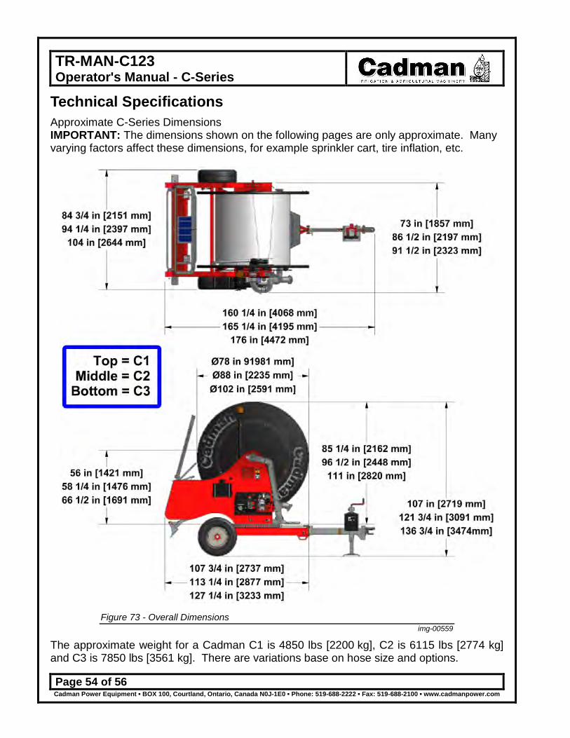
Technical Specifications Approximate C-Series Dimensions IMPORTANT: The dimensions shown on the following pages are only approximate. Many varying factors affect these dimensions, for example sprinkler cart, tire inflation, etc.
Figure 73 - Overall Dimensions
img-00559
The approximate weight for a Cadman C1 is 4850 lbs [2200 kg], C2 is 6115 lbs [2774 kg] and C3 is 7850 lbs [3561 kg]. There are variations base on hose size and options.

TR-MAN-C123 Operator's Manual - C-Series
Page 55 of 56 Cadman Power Equipment ▪ BOX 100, Courtland, Ontario, Canada N0J-1E0 ▪ Phone: 519-688-2222 ▪ Fax: 519-688-2100 ▪ www.cadmanpower.com
TR-MAN-C123 Operator's Manual - C-Series
Page 56 of 56 Cadman Power Equipment ▪ BOX 100, Courtland, Ontario, Canada N0J-1E0 ▪ Phone: 519-688-2222 ▪ Fax: 519-688-2100 ▪ www.cadmanpower.com
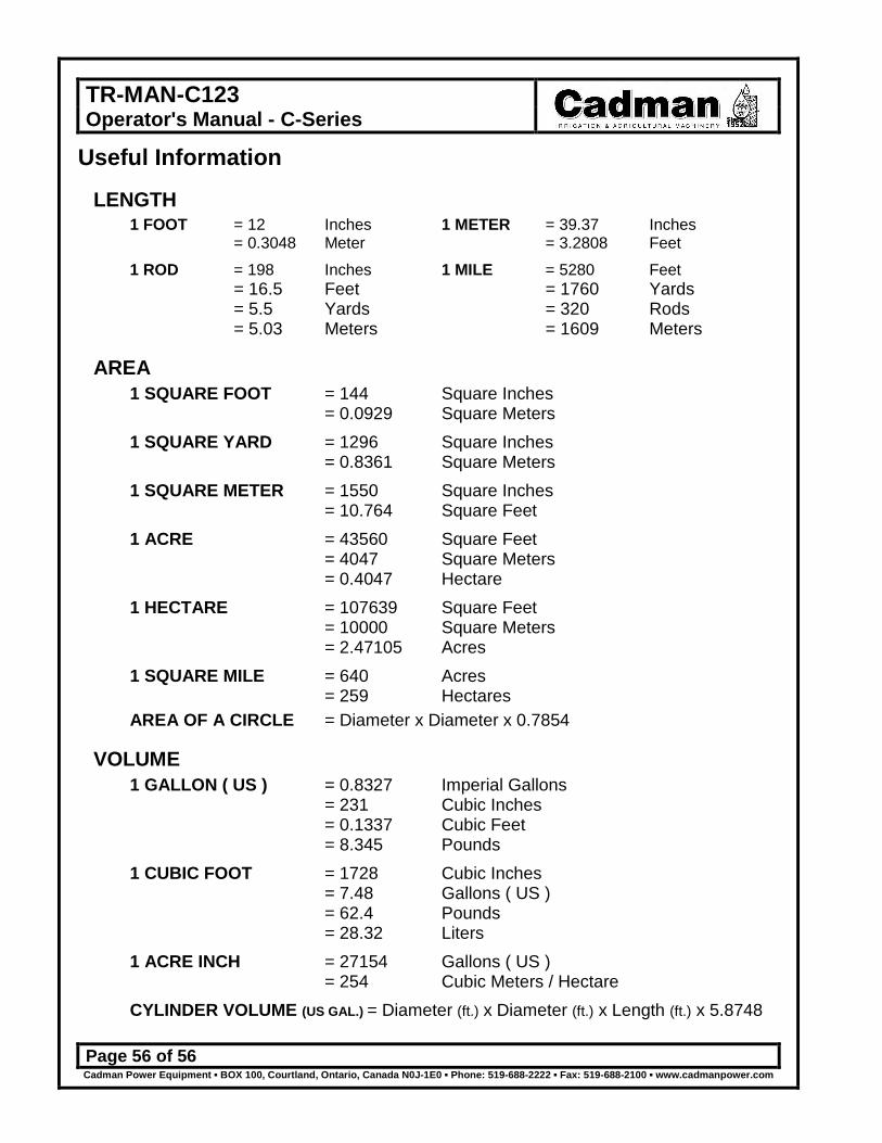
Useful Information
LENGTH 1 FOOT = 12 Inches 1 METER = 39.37 Inches = 0.3048 Meter = 3.2808 Feet 1 ROD = 198 Inches 1 MILE = 5280 Feet = 16.5 Feet = 1760 Yards = 5.5 Yards = 320 Rods = 5.03 Meters = 1609 Meters
AREA 1 SQUARE FOOT = 144 Square Inches
= 0.0929 Square Meters 1 SQUARE YARD = 1296 Square Inches
= 0.8361 Square Meters 1 SQUARE METER = 1550 Square Inches = 10.764 Square Feet 1 ACRE = 43560 Square Feet = 4047 Square Meters = 0.4047 Hectare
1 HECTARE = 107639 Square Feet = 10000 Square Meters = 2.47105 Acres
1 SQUARE MILE = 640 Acres = 259 Hectares
AREA OF A CIRCLE = Diameter x Diameter x 0.7854
VOLUME 1 GALLON ( US ) = 0.8327 Imperial Gallons
= 231 Cubic Inches = 0.1337 Cubic Feet = 8.345 Pounds
1 CUBIC FOOT = 1728 Cubic Inches = 7.48 Gallons ( US ) = 62.4 Pounds = 28.32 Liters
1 ACRE INCH = 27154 Gallons ( US ) = 254 Cubic Meters / Hectare
CYLINDER VOLUME (US GAL.) = Diameter (ft.) x Diameter (ft.) x Length (ft.) x 5.8748