c s 3 0 7 d a t a c o m m u n i c a t i o n - mo d u l e i i i
TRANSCRIPT
CS 307 Data Communication-
Module III Syllabus Signal Encoding techniques - Digital Data Digital Signals: NRZ, Multilevel binary, Biphase – Digital Data Analog Signals : ASK, FSK, PSK - Analog Data Digital Signals: Sampling theorem, PCM, Delta Modulation - Analog Data Analog Signals: AM, FM, PM.
Signal Encoding techniques A computer network is designed to send information from one point to another. This information needs to be converted to either a digital signal or an analog signal for transmission.
• Digital Data To Digital Signal Transmission • Analog Data To Digital Signal Transmission • Digital Data To Analog Signal Transmission • Analog Data To Analog Signal Transmission
Digital Data To Digital Signal Transmission
In these techniques, we represent digital data by using digital signals. The conversion involves three techniques:
● Line coding ● Block coding ● Scrambling.
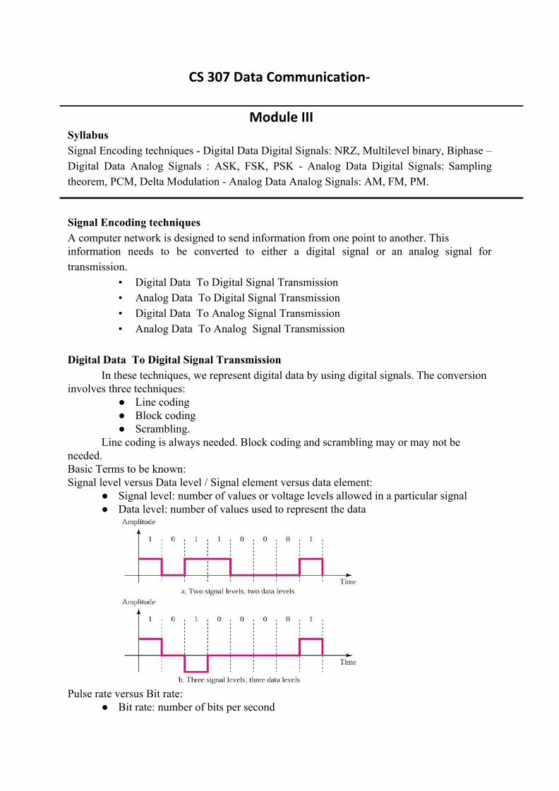
Line coding is always needed. Block coding and scrambling may or may not be needed. Basic Terms to be known: Signal level versus Data level / Signal element versus data element:
● Signal level: number of values or voltage levels allowed in a particular signal ● Data level: number of values used to represent the data
Pulse rate versus Bit rate:
● Bit rate: number of bits per second

● Pulse rate: o also termed as signal rate / baud rate / modulation rate o Defined as Number of signals or pulses per second. o BitRate=PulseRate* log2L
Where L number of data levels. o PulseRate=1/PulseDuration
Baseline Wandering : In decoding a digital signal, the receiver calculates a running average of the received
signal power. This average is called the baseline. The incoming signal power is evaluated against this baseline to determine the value of the data element. A long string of Os or 1s can cause a drift in the baseline (baseline wandering) and make it difficult for the receiver to decode correctly. A good line coding scheme needs to prevent baseline wandering. DC Components :
When the voltage level in a digital signal is constant for a while, the spectrum creates very low frequencies. These frequencies around zero, called DC (direct-current) components, present problems for a system that cannot pass low frequencies or a system that uses electrical coupling Self-synchronization: To correctly interpret the signals received from the sender, the receiver's bit intervals must correspond exactly to the sender's bit intervals. If the receiver clock is faster or slower, the bit intervals are not matched and the receiver might misinterpret the signals. A self-synchronizing digital signal includes timing information in the data being transmitted. This can be achieved if there are transitions in the signal that alert the receiver to the beginning, middle, or end of the pulse. Q Calculate the pulse rate and bit rate if the Signal has 2 data levels with a pulse duration of
1 ms. (Ans: 1000 pulses/s,1000bps)
Line coding Line coding is the process of converting digital data to digital signals. We assume that data, in the form of text, numbers, graphical images, audio, or video, are stored in computer memory as sequences of bits .Line coding converts a sequence of bits to a digital signal. At the sender, digital data are encoded into a digital signal; at the receiver, the digital data are recreated by decoding the digital signal.

Line coding schemes:
Unipolar : Non Return to Zero (NRZ)
● Uses only one polarity(+ve or –ve voltage). ● polarity is assigned to any 1 data bit, normally 1. ● positive voltage defines bit 1 and zero voltage defines bit O. ● It is called NRZ because the signal does not return to zero at the middle of the bit
Polar Encoding Schemes
● Normally Uses two voltage levels, one positive and one negative ● Different types:
o NRZ –L o NRZ –I o RZ o Biphase schemes: Manchester & Differential Manchester
Polar :Nonreturn to Zero-Level (NRZ-L) ● two different voltages for 0 and 1 bits;normally we take positive voltage for bit 0
and negative for bit 1 ● voltage constant during bit interval i.e no transition (return) to zero voltage in
between a bit & hence the name ● Level of the signal is dependent on the state of the bit
Polar :Nonreturn to Zero Inverted (NRZ-I) ● Signal is inverted if bit 1 is encountered.
o transition (low to high or high to low) denotes binary 1 o no transition denotes binary 0

Polar :Return to Zero (RZ)
● uses three values: positive, negative, and zero. ● In RZ, the signal changes not between bits but during the bit. ● signal returns to 0 in the middle of each bit. ● 1 represent positive to zero and 0 represent negative to zero
Biphase schemes
● Manchester Encoding o has transition in middle of each bit period o low to high ( i.e negative to positive voltage) represents one o high to low (positive to negative) represents zero
● Differential Manchester Encoding o If bit is 0,there is transition o If bit is 1,there is no transition
Bipolar : Multi Level Binary Schemes
● Use 3 voltage levels: zero, positive & negative ● Bipolar-AMI (Alternate mark inversion)

o zero represented by zero voltage o one represented by alternative positive or negative pulse
● Pseudoternary o one represented by zero voltage o zero represented by alternative positive or negative pulse o AMI & Pseudoternary
Q Summarize the characteristics of various line coding schemes
Q Encode the data 100110 using various polar schemes
Block coding :
We need redundancy to ensure synchronization and to provide some kind of inherent
error detecting. Block coding can give us this redundancy and improve the performance of line coding. In general, block coding changes a block of m bits into a block of n bits, where n is larger than m. Block coding is referred to as an mB/nB encoding technique.

Block coding normally involves three steps: division, substitution, and combination. In the division step, a sequence of bits is divided into groups ofm bits. For example, in 4B/5B encoding, the original bit sequence is divided into 4-bit groups. The heart of block coding is the substitution step. In this step, we substitute an m-bit group for an n-bit group.For example, in 4B/5B encoding we substitute a 4-bit code for a 5-bit group. Finally, the n-bit groups are combined together to form a stream. The new stream has more bits than the original bits. Block coding Schemes
The major schemes are: o 4B/5B o 8B/10B
4B/5B Block coding Scheme:
In 4B/5B, the 5-bit output that replaces the 4-bit input has no more than one leading zero (left bit) and no more than two trailing zeros (right bits). So when different groups are combined to make a new sequence, there are never more than three consecutive bits
8B/10B Block coding Scheme:

The eight binary/ten binary (8B/10B) encoding is similar to 4B/5B encoding except that a group of 8 bits of data is now substituted by a 10-bit code. It provides greater error detection capability than 4B/5B. The 8B/10B block coding is actually a combination of 5B/6B and 3B/4B encoding. Scrambling techniques:
A long sequence of 0s upsets the synchronization. If we can find a way to avoid a long sequence of 0s in the original stream, we can use bipolar AMI for long distances. We are looking for a technique that does not increase the number of bits and does provide synchronization.Scrambling techniques substitute long zero-level pulses with a combination of other levels to provide synchronization. Two common scrambling techniques are B8ZS and HDB3. B8ZS
● In general BnZS scheme: where n consecutive zeroes are replaced by a specific pattern.
● In B8ZS : Eight consecutive zeroes replaced by sequence 000VB0VB, where “V “ means violates AMI rule .i.e same polarity as the polarity of previous non zero pulse, “B“ means according to AMI rule .i.e opposite polarity to the previous non zero pulse
HDB3
● Four consecutive level 0 voltages are replaced with 000V or B00V ● 2 different substitutions to maintain even number of non zero pulses ● Rules :
o If the number of non zero pulses after last substitution is odd, substitute with 000V
o If the number of non zero pulses after last substitution is even, substitute with B00V

Other Schemes
● 2B1Q: o uses 4 voltage levels, each pulse represent 2 bits o Multi Level Scheme
● MLT-3: Multi Line Transmission-3 level
o Uses 3 levels of signals(+1,0,-1) o Signal transition from one to next level if bit 1, no transition for bit 0.
Q Write short notes on: (i) B8ZS (ii) HDB3. Q Explain the difference between NRZL and NRZI? Q Describe two multilevel binary digital to digital encoding techniques? Q Define Biphase encoding and describe two Biphase encoding techniques? Q Describe different digital signal encoding format. With the help of neat diagrams,
represent the digital data 01001100011. Q What is meant by line coding? Encode 11 0 11 by AMI, differential Manchester and polar
RZ techniques. Q Encode the data 01010011 by NRZ-L, AMI, Manchester and Differential Manchester
techniques. Q What is differential encoding?
In digital communications,differential coding is a technique used to provide unambiguous signal reception when using some types of modulation. It makes data to be transmitted to depend not only on the current bit (or symbol), but also on the previous one.
Analog Data To Digital Signal Transmission

In Analog Data To Digital Signal Transmission , analog signal such as one created by a microphone or camera are converted to digital data. After the digital data are created (digitization), digital to digital encoding schemes are used to convert the digital data to a digital signal.
Digitization is conversion of analog data into digital data. The analog to digital conversion is done using a codec (coder-decoder) . The two techniques used are pulse code modulation and delta modulation. Pulse Code Modulation (PCM)
A PCM encoder has three processes
1.The analog signal is sampled. 2. The sampled signal is quantized. 3. The quantized values are encoded as streams of bits.
PCM is based on sampling theorem ( Nyquist Frequency): ● “If a signal is sampled at regular intervals at a rate higher than twice the
highest signal frequency, the samples contain all information in original signal”
● eg. For voice signal with frequency less than 4000Hz, 8000 sample per sec is enough for reproducing the signal completely
Each PAM sample is approximated by being quantized in to 16 levels; each sample then
represented by 4 bits. PCM starts with a continuous-time, continuous-amplitude (analog) signal , from which a digital signal is produced. On reception, the process is reversed to reproduce the analog signal.By quantizing the PAM pulse, the original signal is now only

approximated and cannot be recovered exactly. This effect is known as quantizing error or quantizing noise .
Number of bits per sample :
n=log2L where L is number of quantization levels.
Eg: If L=16 ,then n=4 Sampling rate= 2*frequency of signal.
Bit Rate= sampling rate*number of bits per sample SNR for quantizing noise
SNRdB=20 log(2n)+1.76 or
SNRdB=6.02 n + 1.76 where n is number of bits per sample
Q Find the bit rate to digitize human voice(4000 Hz) if number of bits per sample is 8. ● Sampling rate = 8000 samples/s

● Bit Rate = 64 Kbps. Q Find SNRdB if n=3
( Ans:SNRdB =19.82 dB) Q A telephone subscriber has SNRdB above 40. Find minimum number of bits per sample.
( Ans: n= 6.35,so taken as 7 bits)
PCM with Non-Linear Coding PCM scheme is refined using a technique known as nonlinear encoding.In this technique,
the quantization levels are not equally spaced. It uses a greater number of quantizing steps for signals of low amplitude and a smaller number of quantizing steps for signals of large amplitude.Non Uniform quantization is achieved by process called companding and expanding.Signal is companded (i.e reducing instantaneous voltage Amplitude) at the sender and expanded at the receiver.Non Uniform quantization reduces SNRdB of quantization.
Delta Modulation
● With delta modulation, an analog input is approximated by a staircase function that moves up or down by one quantization level (δ) at each sampling interval (Ts). The behavior of staircase function is binary: At each sampling time, the function moves up or down a constant amount δ. 1 is generated if the staircase function is to go up during the next interval; and 0 is generated otherwise.

Delta Modulator & Demodulator
The modulator is used at the sender site to create a stream of bits from an
analog signal.The modulator builds a staircase signal against which the analog signal is compared. The process records the small positive or negative changes, called delta δ. If the delta is positive, the process records a 1; if it is negative, the process records a 0. The modulator, at each sampling interval, compares the value of the analog signal with the last value of the staircase signal.If the amplitude of the analog signal is

larger, the next bit in the digital data is 1; otherwise, it is 0. The output of the comparator, however, also makes the staircase itself.
Demodulator takes the digital data and, using the staircase maker and the delay unit, creates the analog signal.The created analog signal, however, needs to pass through a low-pass filter for smoothing.
Adaptive DM : the value of δ is not fixed; it changes according to the amplitude of the analog signal.
Advantages of DM over PCM ● Quantization error is much less than that for PCM ● Less complex in implementation when compared to PCM
Q Describe any two modulation techniques used in codecs. Hint: Analog to digital: Pulse Code Modulation (PCM) & Delta modulation
Q Analyse PCM & DM for encoding analog signals that represent digital data?
Digital Data To Analog Signal Transmission
Digital-to-analog conversion is the process of changing one of the characteristics of an analog signal based on the information in digital data. a sine wave is defined by three characteristics: amplitude,frequency, and phase. When we vary anyone of these characteristics, we create a different version of that wave. So, by changing one characteristic of a simple electric signal, we can use it to represent digital data. Any of the three characteristics can be altered in this way, giving us at least three mechanisms for modulating digital data into an analog signal:amplitude shift keying (ASK), frequency shift keying (FSK), and phase shift keying (PSK). In addition, there is a fourth (and better) mechanism that combines changing both the amplitude and phase, called quadrature amplitude modulation (QAM). QAM is the most efficient of these options and is the mechanism commonly used today
Types of digital-to-analog conversion

Aspects of Digital-to-Analog Conversion
Baseband Signal & Carrier signal o Baseband Signal: the input signal;also called as modulating signal o Carrier signal: high frequency continuous signal produced by the sender
device Data Element Versus Signal Element
o Data element : smallest piece of information to be exchanged i.e bit. o Signal element : smallest unit of a signal o Ratio r :number of data elements carried by each signal
Data Rate Versus Signal Rate o Data rate (N):
▪ number of data elements (bits) sent in 1s. ▪ unit is bits per second (bps). ▪ Also known as bit rate
o Signal rate (S): ▪ number of signal elements sent in 1s. ▪ unit is the baud. ▪ Also known as pulse rate, baud rate, modulation rate ▪ Relationship between S and N
▪ S=N * (1/r) o Where S is the baud rate/signal rate o N is tha data rate/bit rate o r is the ratio .i.e no: of data elements carried in one signal element o For analog transmission :
▪ r=log2 L ; so L=2r ▪ Where L is the no:of signal elments needed for transmission
Amplitude Shift Keying ● Values represented using 2 different amplitudes of carrier frequency ● Normally represented as binary 1 using a constant amplitude and binary 0 with zero
amplitude(ON OFF keying) ● Resulting transmitted signal:

o Where the carrier signal is A cos (2πfct)
Bandwidth : ● B=(1+d) * S
▪ Where B is Bandwidth ,S is signal rate ▪ d is value between 0 and 1 ;depends on modulation & filtering process
Q We have an available bandwidth of 100 kHz which spans from 200 to 300 kHz. What are
the carrier frequency and the bit rate if we modulated our data by using ASK with d =1.(taking r=1)
B=(1+d) * S……..(eqn 1) S=N * (1/r)…………(eqn 2) from eqn 1: 100=(1+1)*S
therefore S= 50 Baud from eqn 2: 50=N*(1/1)
therefore N=50Kbps Binary Frequency Shift Keying
● Frequency of the modulated signal is constant for the duration of one signal element but changes for the next signal element if element changes.
● 2 binary values represented by 2 different frequencies

● Resulting signal:
● Bandwidth of BFSK
o B=(1+d)*S + 2∆f ▪ Where B is Bandwidth ,S is signal rate ▪ d is value between 0 and 1 ▪ 2∆f is the difference between 2 frequencies
Multiple FSK (MFSK)
o More than 2 frequencies used. o for sending 2 bits at a time we can use 4 different frequencies used.
Binary Phase Shift Keying(BPSK) ● 2 signal elements ,one with a phase 00 and other with a phase of 1800 .

Differential PSK (DPSK) ● Binary 0 represented as signal with same phase as previous signal ● Binary 1 represented as signal with opposite phase as previous signal
Quadrature PSK (QPSK)
● 4 level PSK ● Each signal element represents more than 1 bit ● Phase shifts separated by multiples of 90 degree
Multilevel PSK (MPSK):
o Transmitting 3 bits at time using 8 different phase angles Bandwidth of PSK:
● B=(1+d) * S ▪ Where B is Bandwidth ,S is signal rate ▪ d is value between 0 and 1 ;depends on modulation & filtering process
Constellation Diagram A constellation diagram can help us define the amplitude and phase of a signal
element,particularly when we are using two carriers (one in-phase and one quadrature), The diagram is useful when we are dealing with multilevel ASK, PSK, or QAM .In a constellation diagram, a signal element type is represented as a dot. Thebit or combination of bits it can carry is often written next to it.
The diagram has two axes. The horizontal X axis is related to the in-phase carrier;the vertical Y axis is related to the quadrature carrier. For each point on the diagram,four pieces of information can be deduced. The projection of the point on the X axis defines the peak amplitude of the in-phase component; the projection of the point on the Y axis defines the peak amplitude of the quadrature component. The length of the line (vector) that connects the point to the origin is the peak amplitude of the signal element ;the angle the line makes with the X axis is the phase of the signal element.

Q Encode 10100100 using ASK with maximum amplitude 1 Q What are the advantages of QAM over ASK or PSK? Q Describe various modulation techniques for digital data in to analog signal. compare
their efficiencies Q Explain constellation diagram with suitable example Q The telephone line has 4 KHz bandwidth. What is the maximum number of
bits we can send using each of the following techniques? Let d = O. a. ASK b. QPSK c. 16-QAM d.64-QAM We use the formula N = [1/(1 + d)] × r × B, but first we need to calculate the value of r for each case. a. r = log22 = 1 →N= [1/(1 + 0)] × 1 × (4 KHz) = 4 kbps b. r = log24=2 →N = [1/(1 + 0)] × 2 × (4 KHz) = 8 kbps c. r = log216= 4 →N = [1/(1 + 0)] × 4 × (4 KHz) = 16 kbps d. r = log264= 6 →N = [1/(1 + 0)] × 6 × (4 KHz) = 24 kbps
Q Draw the constellation diagram for the following: a. ASK, with peak amplitude values of 1 and 3 b. BPSK, with a peak amplitude value of 2 c. QPSK, with a peak amplitude value of 3 d. 8-QAM with two different peak amplitude values, I and 3, and four different
phases. Q Calculate the baud rate for the given bit rate and type of modulation.
a. 2000 bps, FSK b. 4000 bps, ASK c. 6000 bps, QPSK d. 36,000 bps, 64-QAM We use the formula S = (1/r) × N, but first we need to calculate the value of r for each case. a. r = log22 = 1 →S = (1/1) × (2000 bps) = 2000 baud b. r = log22 = 1 → S = (1/1) × (4000 bps) = 4000 baud c. r = log24 = 2 →S = (1/2) × (6000 bps) = 3000 baud

d. r = log264 = 6 →S = (1/6) × (36,000 bps) = 6000 baud Analog-to-analog conversion Analog-to-analog conversion, or analog modulation, is the representation of analog information by an analog signal. Analog-to-analog conversion can be accomplished in three ways: amplitude modulation (AM), frequency modulation (FM), and phase modulation (PM).
Amplitude Modulation In AM transmission, the carrier signal is modulated so that its amplitude varies with the changing amplitudes of the modulating signal. The frequency and phase of the carrier remain the same; only the amplitude changes to follow variations in the information
The total bandwIdth required for AM can be determined from the bandwidth of the audio signal: BAM =2B. Frequency Modulation
In FM transmission, the frequency of the carrier signal is modulated to follow the changing voltage level (amplitude) of the modulating signal. The peak amplitude and phase of the carrier signal remain constant, but as the amplitude of the information signal changes, the frequency of the carrier changes correspondingly.The total bandwidth required for FM can be determined from the bandwidth of the audio signal: BFM =2(1 + β)B.

Phase Modulation In PM transmission, the phase of the carrier signal is modulated to follow the changing voltage level (amplitude) of the modulating signal. The peak amplitude and frequency of the carrier signal remain constant, but as the amplitude of the information signal changes, the phase of the carrier changes correspondingly. It can proved mathematically that PM is the same as FM with one difference. In FM, the instantaneous change in the carrier frequency is proportional to the amplitude of the modulating signal; in PM the instantaneous change in the carrier frequency is proportional to the derivative of the amplitude of the modulating signal.
Q Explain amplitude ,frequency and phase modulation. Q Differentiate AM and FM.
Previous Year KTU University questions
1. Find the Bandwidth for a signal transmitting at 12 Mbps for QPSK. The value of d=0.
2. Encode the given bit stream using NRZ-I. 100010001111 3. With a neat Sketch discuss the various steps involved in PCM. 4. Given the bit pattern 101110001. Encode the stream using BFSK and QPSK. 5. Explain the analog modulation techniques briefly. 6. Give the significance of delta modulation over pulse code modulation during the
process of transforming analog data in to digital signal

7. Show the equivalent analog sine-wave pattern of the bit string 00110101 using amplitude shift keying, frequency shift keying andphase shift keying
8. For the bit stream 11000110010,sketch the wave form for each of the code of NRZ-I.NRZ-L, Bipolar-AMI, Pseudoternary, Manchester, Differential Manchester.
9. Explain the modulation technique used in Asymmetric Digital Subscriber Line (ADSL) and cable modems
10. State Sampling theorem. With help of suitable diagrams, explain the process of transforming analog data in to digital signal using Pulse Code Modulation technique.
11.