c l a m e r a cdp6-16hde3series o w e r i n g s y s t e m...
TRANSCRIPT
835 Industrial Drive Elmhurst, IL 60126, USA PH: 708-681-4330 Fax 708-681-4006 www.lowering-device.com Page 01 Page01-2C-CDP6 16HDBP-092513
C L S
A M E R A O W E R I N G Y S T E M S
Design CDP6-16HDEP SERIESArm and Disconnect Unit for Pole Mount
IP and Analog Surveillance Cameras
H
J
K
A
FH
D
E
C B
G
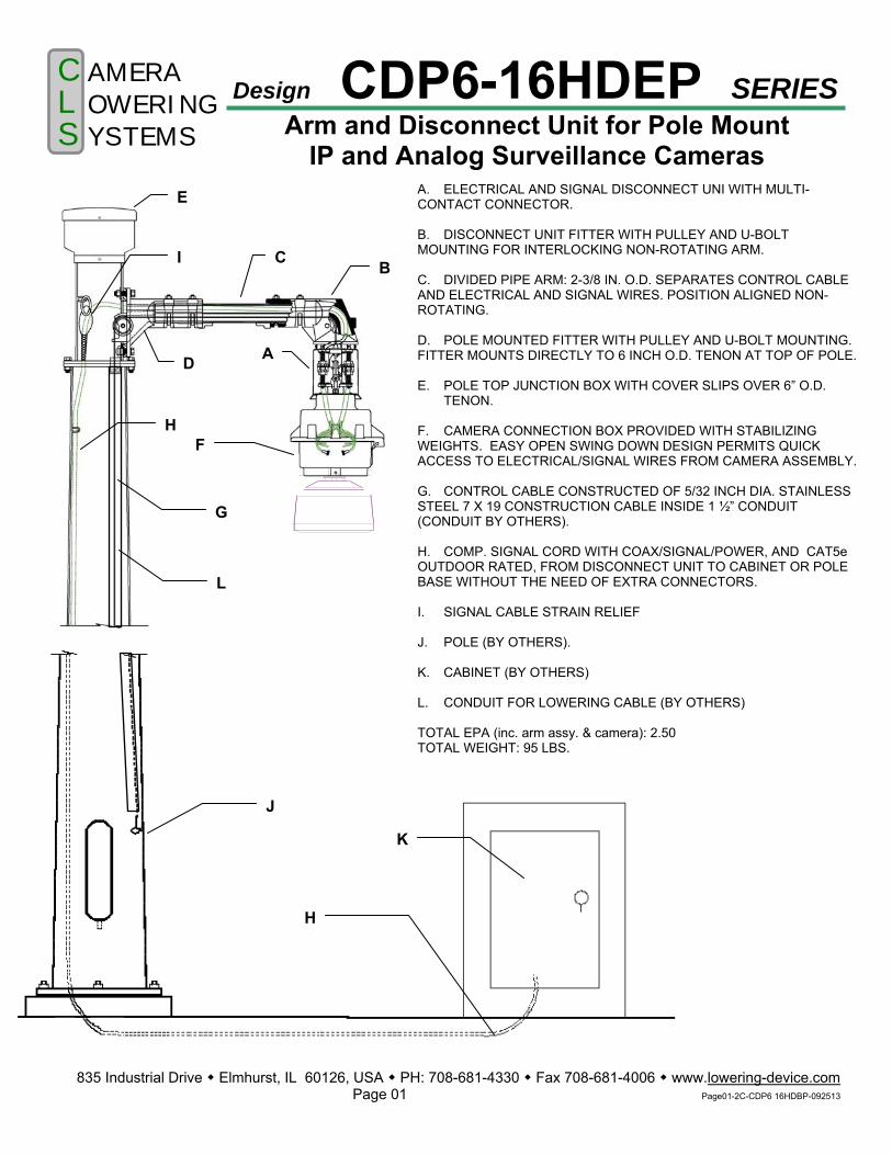
A. ELECTRICAL AND SIGNAL DISCONNECT UNI WITH MULTI-CONTACT CONNECTOR. B. DISCONNECT UNIT FITTER WITH PULLEY AND U-BOLT MOUNTING FOR INTERLOCKING NON-ROTATING ARM. C. DIVIDED PIPE ARM: 2-3/8 IN. O.D. SEPARATES CONTROL CABLE AND ELECTRICAL AND SIGNAL WIRES. POSITION ALIGNED NON-ROTATING. D. POLE MOUNTED FITTER WITH PULLEY AND U-BOLT MOUNTING. FITTER MOUNTS DIRECTLY TO 6 INCH O.D. TENON AT TOP OF POLE. E. POLE TOP JUNCTION BOX WITH COVER SLIPS OVER 6” O.D.
TENON. F. CAMERA CONNECTION BOX PROVIDED WITH STABILIZING WEIGHTS. EASY OPEN SWING DOWN DESIGN PERMITS QUICK ACCESS TO ELECTRICAL/SIGNAL WIRES FROM CAMERA ASSEMBLY. G. CONTROL CABLE CONSTRUCTED OF 5/32 INCH DIA. STAINLESS STEEL 7 X 19 CONSTRUCTION CABLE INSIDE 1 ½” CONDUIT (CONDUIT BY OTHERS). H. COMP. SIGNAL CORD WITH COAX/SIGNAL/POWER, AND CAT5e OUTDOOR RATED, FROM DISCONNECT UNIT TO CABINET OR POLEBASE WITHOUT THE NEED OF EXTRA CONNECTORS. I. SIGNAL CABLE STRAIN RELIEF J. POLE (BY OTHERS). K. CABINET (BY OTHERS) L. CONDUIT FOR LOWERING CABLE (BY OTHERS) TOTAL EPA (inc. arm assy. & camera): 2.50 TOTAL WEIGHT: 95 LBS.
I
L
C L S
A M E R A O W E R I N G Y S T E M S
SPECIFICATIONS FOR 16HD ELECTRICAL DISCONNECT UNIT
835 Industrial Drive Elmhurst, IL 60126 PH: 708-681-4330 Fax 708-681-4006 www.Lowering-Device.com Page 2 Page02-EDU-091913
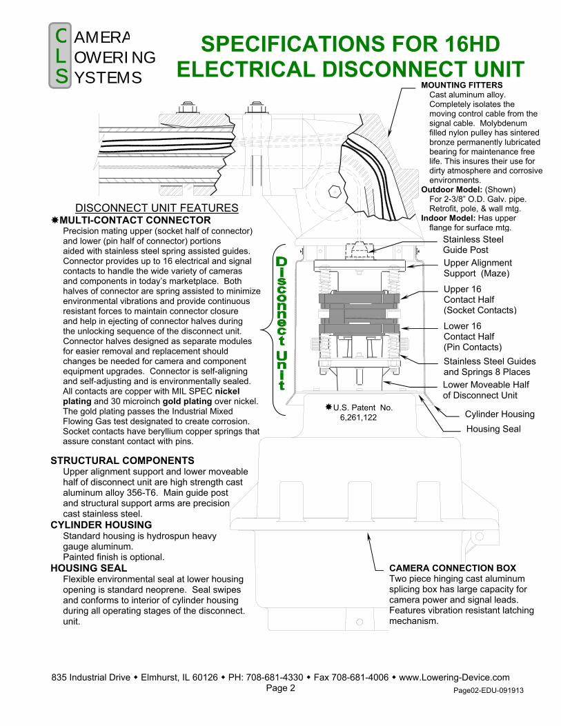
DISCONNECT UNIT FEATURES MULTI-CONTACT CONNECTOR
Precision mating upper (socket half of connector) and lower (pin half of connector) portions aided with stainless steel spring assisted guides. Connector provides up to 16 electrical and signal contacts to handle the wide variety of cameras and components in today’s marketplace. Both halves of connector are spring assisted to minimize environmental vibrations and provide continuous resistant forces to maintain connector closure and help in ejecting of connector halves during the unlocking sequence of the disconnect unit. Connector halves designed as separate modules for easier removal and replacement should changes be needed for camera and component equipment upgrades. Connector is self-aligning and self-adjusting and is environmentally sealed. All contacts are copper with MIL SPEC nickel plating and 30 microinch gold plating over nickel. The gold plating passes the Industrial Mixed Flowing Gas test designated to create corrosion. Socket contacts have beryllium copper springs that assure constant contact with pins.
STRUCTURAL COMPONENTS Upper alignment support and lower moveable
half of disconnect unit are high strength cast aluminum alloy 356-T6. Main guide post and structural support arms are precision cast stainless steel.
CYLINDER HOUSING Standard housing is hydrospun heavy gauge aluminum.
Painted finish is optional. HOUSING SEAL Flexible environmental seal at lower housing opening is standard neoprene. Seal swipes and conforms to interior of cylinder housing during all operating stages of the disconnect. unit.
MOUNTING FITTERSCast aluminum alloy. Completely isolates the moving control cable from the signal cable. Molybdenum filled nylon pulley has sintered bronze permanently lubricated bearing for maintenance free life. This insures their use for dirty atmosphere and corrosive environments.
Outdoor Model: (Shown) For 2-3/8” O.D. Galv. pipe. Retrofit, pole, & wall mtg.
Indoor Model: Has upper flange for surface mtg.
Stainless SteelGuide Post Upper Alignment Support (Maze)
Upper 16 Contact Half (Socket Contacts)
Lower 16 Contact Half (Pin Contacts)Stainless Steel Guidesand Springs 8 Places Lower Moveable Half of Disconnect Unit
Cylinder Housing Housing Seal
CAMERA CONNECTION BOX Two piece hinging cast aluminum splicing box has large capacity for camera power and signal leads. Features vibration resistant latching mechanism.
U.S. Patent No. 6,261,122

1/ 2 ‘D’
1/ 2 ‘D’
‘D’
C L S
A M E R A O W E R I N G Y S T E M S
835 Industrial Drive Elmhurst, IL 60126, USA Phone 708-681-4330 Fax 708-681-4006 www.lowering-device.com Page 3
ELECTRICAL DISCONNECT UNITFOR MULTI-FUNCTION CAMERAS
Page03-Contacts-2conn-CAT5e-061711.doc
OPERATION OF THE MULTI-CONTACT CONNECTOR
MULTI-CONTACT CONNECTOR SHOWN IN LOCKED POSITION
MULTI-CONTACT CONNECTOR SHOWN
IN LOCKING OR UNLOCKING POSITION
Distance ‘D’ is the total distance that the disconnect unit must travel to lock and
unlock. This unique design (patented) by Camera Lowering Systems provides spring assisted upper and lower portions of the connector that splits the total travel distance in half, thereby equalizing the retaining forces required toassure a uniform seal. Because the upper half (socket contacts), and the lower half (pin contacts) float within the disconnect unit, the connector is isolated from vibrations that would affect signal discontinuity.
LOCKED POSITION When the disconnect unit is in the locked position, the multi-contact connector has all contacts engaged. Springs are slightly compressed to provide equal and constant pressure against the two halves to maintain an environmental seal. LOCKING POSITION & UNLOCKING POSITION During the operation to lock or unlock the
disconnect unit, the springs of both halves of the connector compress in equal proportions and stainless steel
CONTACTS AND WIRES • Twin connectors provide 16 Heavy Duty size 12
gold plated over nickel, pure copper electrical contacts.
• Contacts are securely contained within a heavy duty polymer body.
• Upper socket and lower pin contact groups are permanently sealed to the connector body with ‘Superflex’ silicone adhesive rubber sealant. This provides a tough waterproof rubber seal formulated to withstand extreme temperature cycling and severe weather conditions.
• Signal shielding and drain wires are continuous. • Wires are up to 16 conductor electrical and signal
wires (CAT5e and RG6 with signal and 14 AWG power cable). See attached cable specs. The contact connector shall accommodate IP camera connections requiring 100baseT – CAT5e certs.
• A one piece composite cable is provided from disconnect unit to cabinet. (Length to be specified)No additional connectors are required at the top of the pole, or anywhere else between the disconnect unit and the cabinet.
IRE SEAL PIN SIDE
SOCKET CONTACTS CRIMPED TO INDIVIDUAL WIRES
SOCKET SIDE WIRE SEAL
LINE OF SEPARATION
PIN CONTACTS CRIMPEDTO INDIVIDUAL WIRES
ELECTRICALAND SIGNAL
WIRES

C L S
A M E R A O W E R I N G Y S T E M S
835 Industrial Drive Elmhurst, IL 60126, USA PH: 708-681-4330 Fax 708-681-4006 www.Lowering-Device.com Page 4
16HD DISCONNECT UNIT FOR MULTI-FUNCTION CAMERAS
Page04-16HD Specs-092013
OPERATION OF THE MULTI-CONTACT CONNECTOR
guide posts move through linear bearings as the support arms of the disconnect unit move into the proper position within the tracking guide. Electrical and signal contacts remain fully engaged and the camera is still operational. RAISING POSITION The connector assembly utilizes precision machined 4 stainless steel guides to align the two halves of the connector. These guide pins are longer than the communication pins and must engage first and disengage last. These pins are connected to the disconnect unit causing the unit to be grounded per U.L./CSA ratings of the product. In addition to these pins, a 3-way guide is also used for alignment. A set of alignment posts built into the connector halves serve as the final guides to assure that all pin and socket contacts are perfectly aligned before engagement. LOWERING POSITION As the disconnect unit begins to unlock, the springs expand and the guide posts begin to separate. The last parts of the connector to disengage are the electrical and signal contacts. Any ground wires or shielding use a longer pin contact to assure that they are the very last to disengage before the camera is lowered for servicing.
Upper Half Of Connector
Lower Half Of Connector
UPPER MTG. PLATE
STAINLESS STEEL COMPRESSION SPRING (4)
WIRE SEAL
STAINLESS STEELGUIDE POST (2)
CONNECTOR GUIDE
SOCKET BODY
PIN BODY GUIDE POST RECEIVER
WIRE SEAL
LOWER MTG. PLATE
LINEAR BEARING
ELECTRICAL DISCONNECT UNIT (EDU) SPECIFICATION GUIDE
The coaxial and electrical disconnect unit shall meet or exceed sine vibration tests of 3.5 g’s within the frequency range of 5-60 Hz in all three axes for minimum of six 5-minute cycle each axes. It shall meet or exceed random vibration tests of frequency range 60-1000 HZ at .025 g2/Hz applied for 30 minutes in each of the three axes. It shall have results to exhibit no signal or electrical discontinuities greater than 10 microseconds. Tests applicable to Electrical Disconnect Unit and attached components. Contact connections shall be capable of passing EIA-232, EIA-422, EIA-485 and Ethernet data signals and 1 Vp-p video signals, as well as 120VAC, 9-24VAC and 9-48VDC. The EDU shall have a 3-way tracking guide and support. It shall be constructed of precision cast high strength aluminum alloy 356-T6. A permanently fixed position piece incorporating a special tracking guide system permits the moveable portion of the Disconnect Unit to align in the same position every time the system is operated, thereby eliminating the need to re-orientate the camera. The Electrical Disconnect Unit shall have twin high strength notches securing the load of the Lower Contact Assembly and camera. The MULTI-CONTACT Connector assembly shall be modular for easy installation and retrofit requirements. All pin and socket contacts shall be insertable and removable. The connector shall have 16 copper alloy C14500, size 12 contacts (.100” Dia.) rated at 35 Amps with gold plating over nickel per MIL-G-45204. All hardware shall be corrosion resistant stainless steel. It shall have a self-aligning and self-adjusting mechanical system comprised of two principal assemblies: Two UPPER CONTACT HALVES shall house the socket contacts. It shall incorporate spring assisted polymer contact body with precision-machined guideposts. The socket contact body shall have integral guideposts for precise contact alignment. Two LOWER CONTACT HALVES shall house the pin contacts comprised of spring assisted polymer contact body with precision-machined guidepost receivers. The pin contact body aligns with guideposts of integral socket body guideposts. CYLINDER-The cover shall be a one-piece hydro-spun heavy gauge aluminum. The cylinder must utilize stainless steel mounting hardware with O-Ring imbedded washers. The unit must exceed the ingress protection rating of IP55. The unit shall have a guidepost constructed of precision cast high strength stainless steel. It shall utilize a cast-in-place guide bar for precise alignment of Lower Contact Assembly with the fixed portion of the EDU. If required, connectors in the pole top junction box and camera junction box are provided by others.
C L S
A M E R A O W E R I N G Y S T E M S
SPECIFICATION GUIDE FOR POLE MOUNT CAMERA LOWERING SYSTEMS
835 Industrial Drive Elmhurst, IL 60126, USA PH: 708-681-4330 Fax 708-681-4006 www.Lowering-Device.com Page 05
Page05-CDP6 Specification Guide-092013
THERE ARE TWO LOCKING CAMS that suspend the weight of the camera and camera junction box when the unit is in the locked position. The Locking Cams are rated to handle loads up to 400 lbs with a 6:1 safety factor. When in the locked position, all stress is released from the lowering cable. SPECIFICATIONS FOR OTHER COMPONENTS FOR POLE MOUNT A DISCONNECT UNIT FITTER shall be provided made of heavy duty cast aluminum alloy to fit a 2-3/8 inch (60.3mm) outside diameter Divided Pipe Arm. Two U-bolt pipe clamps shall be used to rigidly hold the Divided Pipe Arm. The fitter is designed to completely isolate the moving Control Cable from the electrical and signal wires. It shall contain a molybdenum impregnated nylon pulley providing high strength and low resistance for the moving Control Cable, thereby increasing the life of the cable. The pulley shall have a permanently lubricated bearing. The system shall have a POLE MOUNTED FITTER made of heavy duty cast aluminum alloy to fit 2-3/8 inch (60.3mm) O.D. Divided Pipe Arm. It shall utilize a cast-in-place cable stop to prevent cable connections from entering pulley. It shall contain a molybdenum impregnated nylon pulley with a permanently lubricated bearing. Two U-bolt pipe clamps shall be used to rigidly hold the Divided Pipe Arm. The fitter shall be designed to bolt directly to a 6” (152.4mm) Diameter pole top. The system shall have a horizontal divided pipe arm that fits inside and connects the Disconnect Unit Fitter with the Pole Mounted Fitter. It shall be made of 2-3/8 inch (60.3mm) O.D. with ¼” (6.4mm) wall thickness steel pipe with galvanized finish standard (polyester powder coat painted finish optional). The pipe shall be divided entire length to keep Control Cable and electrical/signal wires separate. Arm shall be position aligned non-rotating type incorporating interlocking positioning keys. The system shall have a POLE TOP CONNECTION BOX made of cast aluminum. The box shall be 8-inch (203mm) diameter with the bottom portion made to fit over a 6” (152.4mm) O.D. Diameter pole top tenon. It shall be secured to the pole using stainless steel screws. The connection box shall have a cast aluminum cover retained by stainless steel screws. The box shall incorporate bosses for direct mounting of cord strain relief brackets and cord grips. It shall also be used to terminate the socket connectors at a terminal block located in the pole-top connection box. If preferred, the Signal Cable can be a one piece from disconnect unit to pole base or cabinet to eliminate need of a connector at top of pole.
The system shall utilize a CONTROL CABLE (mechanical raising and lowering cable) made of type 316 Stainless Steel 5/32 inch (3.8mm) diameter 7 x 19 construction cable. The cable should be manufactured so as not to unwind or become unraveled during the raising and lowering operation. Minimum breaking strength shall be 2400 lbs. One end of the cable shall have a heavy-duty Stainless Steel connecting link. The control cable shall be the only cable that moves when the camera is raised and lowered. The system shall also have a CAMERA CONNECTION BOX. It shall be a two piece design for easy camera mounting. Both sections shall be made of corrosion resistant cast aluminum. The top half shall be mounted and gasketed to the bottom of the disconnect unit. Inside the top half, it shall have provision to mount additional weights for lightweight cameras or other equipment. All parts shall be made of extra heavy construction. The Camera Connection Box shall be adaptable to all brands of cameras. The two piece construction shall feature a lower box that hinges down for easy access to wiring. It shall contain a large capacity-splicing compartment for camera power, signal leads, and connectors. All hardware shall be made of stainless steel. An LT-CC LOWERING TOOL shall be supplied with each order. It is a portable lowering tool consisting of the gearbox, disc brake, frame, and lowering cable. The gearbox shall be of heavy-duty design. It shall incorporate solid steel heated treated gears for maximum durability and strength. The gearbox shall be equipped with a special automatically actuated disc brake for load holding ability and the prevention the load from freewheeling. This is essential for all lifting operations. The winch has a 3:1 Gear reduction to reduce the effort required to raise and lower the camera assembly. The frame shall be of a heavy-duty design with brackets making the unit stable when mounted in the pole handhole. The frame shall have a pulley with a permanently lubricated bearing. The raising and lowering (control) cable shall be made of stainless steel 1/8-inch (3.2mm) diameter 7 x 19 construction. Minimum breaking strength shall be 1760lbs. It shall come with a heavy-duty stainless steel swivel. Length of tool cable shall be long enough to allow cable to wind evenly on winch drum and not bind during operation.

INTERLOCKING ARM & FITTERS
PROVIDES POSITIVE NON-ROTATING POSITIONING OF PIPE ARM FOR ALL OUTDOOR
POLE AND WALL MOUNTED LOWERING SYSTEMSCONTINUOUSLY DIVIDED 2-3/8 IN. O.D. STEEL PIPE ARM WITH WELDED POSITIONING KEYS, HOT DIPPED GALVANIZED.
POLE OR WALLMOUNT FITTER
DISCONNECTUNIT FITTER
WIRES
VIEW A (BOTTOM SIDE)
DIVIDED PIPE ARM TOTAL EPA: 2.50 TOTAL WEIGHT: 95 LBS (includes arm, disconnect unit, pole and camera junction boxes, & camera)
POLE MOUNT ORWALL MOUNT
FITTER
INTERLOCKING POSITIONING KEYSWELDED TO PIPE ARM
CLAMPINGU-BOLTS
4 PLACES
CLS
A M E R AO W E R I N GY S T E M S
OPERATING CABLE
SEE ENLARGED DETAIL VIEW ‘A’
POSITIONING KEYS
DISCONNECTUNIT FITTER
FEATURES Specially shaped steel keys are welded to divided pipe arm before arm is galvanized. Precise alignment of keys with corresponding notches in the pole/wall fitter and the disconnect unit fitter provide positive positioning and prevents rotating of components about the divided pipe arm during extreme environmental conditions. Pipe arm has full length divider separating the wires from the movement of the control cable. Separate chambers within the fitters for electrical wires and the control cable assures complete protection to the wires during the operation of the system.
835 Industrial Drive Elmhurst, IL 60126, USA PH: 708-681-4330 Fax 708-681-4006 www.Lowering-Device.com Page 6 Page06-Interlocking Arms-2conn-082213 D.P.

ARM CROSS SECTION
UPPER CHAMBER FOR ELECTRICAL WIRES
LOWER CHAMBER FOR CONTROL CABLE
DIVIDER
KEYS ON ARM INTERLOCK WITH NOTCHES IN FITTERS TO PROVIDE POSITIVE NON-ROTATING COMPONENTS OF ARM ASSEMBLY. PRECISE ALIGNMENT OF KEYS AND FITTER NOTCHES ELIMINATE ANY NEED FOR ADJUSTMENT.
DETAILS OF FEATURES NOTE: WHEN THE INTERLOCKING POSITIONING KEYS OF THE ARM ASSEMBLY ARE MATED WITH THE CORRESPONDING NOTCHES IN THE FITTERS, THE POLE SHAFT MUST BE PLUMB FOR THE PROPER OPERATION OF THE SYSTEM. ANGLE α: The angle α shown in the END VIEW is based on mechanical tolerances between mating parts and should not exceed a total of 1/2 °. This deviation from plumb will not affect the operation of the components of the arm assembly. All tolerances are based on the pole shaft being plumb when installed. PIPE ARM: (See Fig. 1) Constructed of 2 inch structural
steel pipe having an outside diameter of 2-3/8 inch. Positioning keys are permanently welded to the pipe arm at precise positions that align with notches in the ends of each of the fitters. Arm finish is hot dip galvanized after all welding is completed. Optional finishes over the galvanizing are available to match the color of the pole. Ends of the pipe arm bottom out against the inside of the fitters a small fraction of an inch before the keys bottom out in the notches to provide a secure fit. The pipe arm is installed complete with the rest of the arm components at the factory and is pre-wired to eliminate any need for adjustment in the field.
Fig. 1
END VIEW
α
1/4’’
1/2’’
PIPE ARM OUTLINE
835 Industrial Drive Elmhurst, IL 60126 USA PH: 708-681-4330 Fax 708-681-4006 www.Lowering-Device.com Page 07
Page07-Frontal Interlocking Arms-082013
C L S
A M E R A O W E R I N G Y S T E M S
INTERLOCKING ARM & FITTERS
PROVIDES POSITIVE NON-ROTATING POSITIONING OF PIPE ARM FOR ALL OUTDOOR
POLE AND WALL MOUNTED LOWERING SYSTEMS
835 Industrial Drive Elmhurst, IL 60629, USA PH: 708-681-4330 FAX: 708-681-4006 www.Lowering-Device.com Page 8E E-663213RG608-8-COND RG6-013114
CLS
A M E R AO W E R I N GY S T E M S
SPECIFICATION SHEET“E” Style Composite Cable
Composite Cable for 16HD-E connector
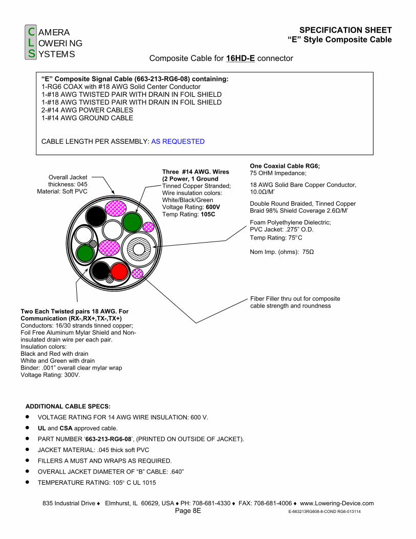
“E” Composite Signal Cable (663-213-RG6-08) containing: 1-RG6 COAX with #18 AWG Solid Center Conductor 1-#18 AWG TWISTED PAIR WITH DRAIN IN FOIL SHIELD 1-#18 AWG TWISTED PAIR WITH DRAIN IN FOIL SHIELD 2-#14 AWG POWER CABLES 1-#14 AWG GROUND CABLE CABLE LENGTH PER ASSEMBLY: AS REQUESTED
ADDITIONAL CABLE SPECS:
VOLTAGE RATING FOR 14 AWG WIRE INSULATION: 600 V.
UL and CSA approved cable.
PART NUMBER ‘663-213-RG6-08’, (PRINTED ON OUTSIDE OF JACKET).
JACKET MATERIAL: .045 thick soft PVC
FILLERS A MUST AND WRAPS AS REQUIRED.
OVERALL JACKET DIAMETER OF “B” CABLE: .640”
TEMPERATURE RATING: 105 C UL 1015
Overall Jacketthickness: 045
Material: Soft PVC
One Coaxial Cable RG6; 75 OHM Impedance;
18 AWG Solid Bare Copper Conductor, 10.0Ω/M’
Double Round Braided, Tinned Copper Braid 98% Shield Coverage 2.6Ω/M’
Foam Polyethylene Dielectric; PVC Jacket: .275” O.D. Temp Rating: 75C Nom Imp. (ohms): 75Ω
Two Each Twisted pairs 18 AWG. For Communication (RX-,RX+,TX-,TX+) Conductors: 16/30 strands tinned copper; Foil Free Aluminum Mylar Shield and Non-insulated drain wire per each pair. Insulation colors: Black and Red with drain White and Green with drain Binder: .001” overall clear mylar wrap Voltage Rating: 300V.
Fiber Filler thru out for composite cable strength and roundness
Three #14 AWG. Wires (2 Power, 1 Ground Tinned Copper Stranded; Wire insulation colors: White/Black/Green Voltage Rating: 600V Temp Rating: 105C
CLS
A M E R AO W E R I N GY S T E M S
835 Industrial Drive ♦ Elmhurst, IL 60126, USA ♦PH: 708-681-4330 ♦ FAX: 708-681-4006 ♦ www.Lowering-Device.com Page 08P P-663-241-CAT5E-Page 08P-032814
SPECIFICATION SHEET “P” CAT 5e Cable
CAT 5e ETHERNET CABLE WITH EXTREME CONDITION
FR-TPE FOIL SHIELDED CABLE
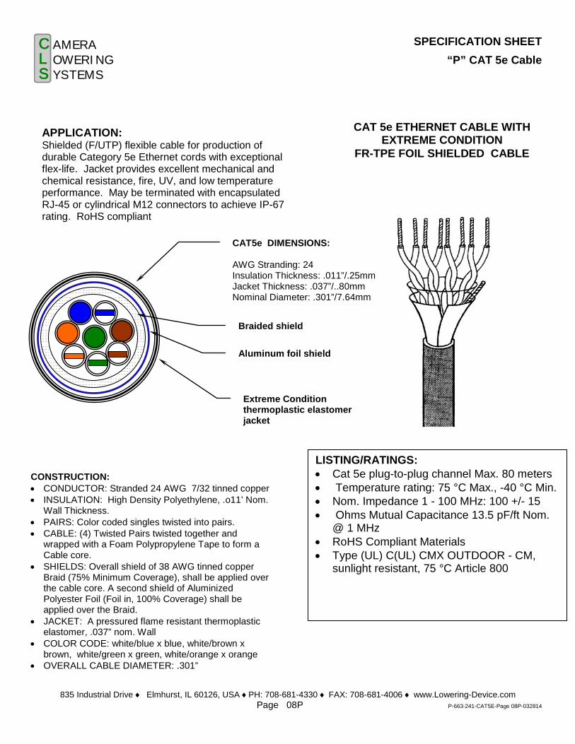
APPLICATION: Shielded (F/UTP) flexible cable for production of durable Category 5e Ethernet cords with exceptional flex-life. Jacket provides excellent mechanical and chemical resistance, fire, UV, and low temperature performance. May be terminated with encapsulated RJ-45 or cylindrical M12 connectors to achieve IP-67 rating. RoHS compliant
CONSTRUCTION: • CONDUCTOR: Stranded 24 AWG 7/32 tinned copper • INSULATION: High Density Polyethylene, .o11’ Nom.
Wall Thickness. • PAIRS: Color coded singles twisted into pairs. • CABLE: (4) Twisted Pairs twisted together and
wrapped with a Foam Polypropylene Tape to form a Cable core.
• SHIELDS: Overall shield of 38 AWG tinned copper Braid (75% Minimum Coverage), shall be applied over the cable core. A second shield of Aluminized Polyester Foil (Foil in, 100% Coverage) shall be applied over the Braid.
• JACKET: A pressured flame resistant thermoplastic elastomer, .037” nom. Wall
• COLOR CODE: white/blue x blue, white/brown x brown, white/green x green, white/orange x orange
• OVERALL CABLE DIAMETER: .301”
LISTING/RATINGS: • Cat 5e plug-to-plug channel Max. 80 meters • Temperature rating: 75 °C Max., -40 °C Min. • Nom. Impedance 1 - 100 MHz: 100 +/- 15 • Ohms Mutual Capacitance 13.5 pF/ft Nom.
@ 1 MHz • RoHS Compliant Materials • Type (UL) C(UL) CMX OUTDOOR - CM,
sunlight resistant, 75 °C Article 800
Aluminum foil shield
CAT5e DIMENSIONS: AWG Stranding: 24 Insulation Thickness: .011”/.25mm Jacket Thickness: .037”/..80mm Nominal Diameter: .301”/7.64mm
Extreme Condition thermoplastic elastomer jacket
Braided shield

835 Industrial Drive Elmhurst, IL 60126, USA PH: 708-681-4330 Fax 708-681-4006 www.Lowering-Device.com Page 09
Page09-WireMeshGripandConduitBrkt-092013
CLS
A M E R AO W E R I N GY S T E M S
Composite Cable Cord Grip
SUPPORT GRIPS Standard Duty, Closed Mesh Standard closed mesh support grips are designed for loads up to 600 lbs. and vertical runs of up to 100ft. The different cord grips are used to support electrical/signal cable with a cable diameter ranging from 0.40” to 0.99”. Closed mesh support grips have a loop to hang from the eye hook. Support grips are woven of corrosion-resistant tinned-bronze wire. Optional stainless steel wire mesh also available
Cable Diameter Range
Part
Number
Bale
Length
Mesh
Length
Approximate
Break Strength
0.750-0.990” 662-240-28 8” 14” 1300 LBS
Material
Tinned-bronze
0.400-0.740” 662-248-28 8” 14” 1300 LBS Tinned-bronze
Disconnect Unit Arm Assembly
Tenon “Eye” Bolt
Stainless Steel Connecting Link
Wire Mesh Cord Grip
Composite Cable
5/32” stainless steel Raising and Lowering Cable installed
inside conduit.
Aluminum Schedule 80, 1 1/2” Conduit Bracket with male thread
to attach to PVC pipe inside the pole. Bracket attached to 1/2” bolt
1/2” -13 Bolt
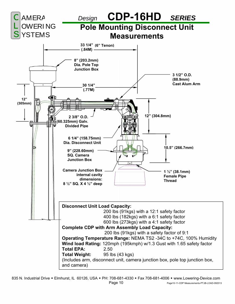
Design CDP-16HD SERIES Pole Mounting Disconnect Unit
Measurements C L S
A M E R A O W E R I N G Y S T E M S
835 N. Industrial Drive Elmhurst, IL 60126, USA PH: 708-681-4330 Fax 708-681-4006 www.Lowering-Device.com Page 10 Page10-11-CDP Measurements-PTJB-LOAD-092013
6 1/4” (158.75mm)Dia. Disconnect Unit
9” (228.60mm) SQ. Camera Junction Box
12” (304.8mm)
10.5” (266.7mm)
2 3/8” O.D. (60.325mm) Galv.
Divided Pipe
8” (203.2mm) Dia. Pole Top Junction Box
Camera Junction Boxinternal cavity
dimensions:8 ½” SQ. X 4 ½” deep
Disconnect Unit Load Capacity: 200 lbs (91kgs) with a 12:1 safety factor
400 lbs (182kgs) with a 6:1 safety factor 600 lbs (273kgs) with a 4:1 safety factor Complete CDP with Arm Assembly Load Capacity: 200 lbs (91kgs) with a safety factor of 9:1 Operating Temperature Range: NEMA TS2 -34C to +74C, 100% Humidity Wind load Rating: 120mph (195kmph) w/1.3 Gust with 1.65 safety factor Total EPA: 2.50 Total Weight: 95 lbs (43 kgs) (Includes arm, disconnect unit, camera junction box, pole top junction box, and camera)
12” (305mm)
3 1/2” O.D. (88.9mm) Cast Alum Arm30 1/4”
(.77M)
1 ½” (38.1mm) Female Pipe Thread
33 1/4” (.84M)
(6” Tenon)
835 Industrial Drive ♦ Elmhurst, IL 60126 ♦ PH: (708) 681-4330 ♦ Fax: (708) 681-4006 ♦ www.Lowering-Device.com Page 11 Page11-CAMJB-10-042514
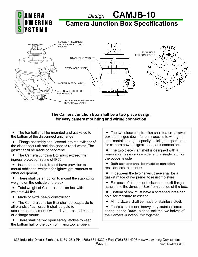
Design CAMJB-10 Camera Junction Box Specifications C
L S
A M E R A O W E R I N G Y S T E M S
FLANGE ATTACHMENT OF DISCONNECT UNIT TO BOX
SINGLE STAINLESS HEAVY DUTY DRAW LATCH
The two piece construction shall feature a lower box that hinges down for easy access to wiring. It shall contain a large capacity-splicing compartment for camera power, signal leads, and connectors.
The two-piece clamshell is designed with a removable hinge on one side, and a single latch on the opposite side.
Both sections shall be made of corrosion resistant cast aluminum.
In between the two halves, there shall be a gasket made of neoprene, to resist moisture.
For ease of attachment, disconnect unit flange attaches to the Junction Box from outside of the box.
Bottom of box must have a screened ‘breather hole’ for moisture to escape.
All hardware shall be made of stainless steel.
There shall be one heavy duty stainless steel spring-loaded Draw Latch to lock the two halves of the Camera Junction Box together.
The top half shall be mounted and gasketed to the bottom of the disconnect unit flange.
Flange assembly shall extend into the cylinder of the disconnect unit and designed to repel water. The gasket shall be made of neoprene.
The Camera Junction Box must exceed the ingress protection rating of IP55.
Inside the top half, it shall have provision to mount additional weights for lightweight cameras or other equipment.
There shall be an option to mount the stabilizing weights on the outside of the box.
Total weight of Camera Junction box with weights: 45 lbs.
Made of extra heavy construction.
The Camera Junction Box shall be adaptable to all brands of cameras. It shall be able to accommodate cameras with a 1 ½” threaded mount, or a flange mount.
There shall be two open safety latches to keep the bottom half of the box from flying too far open.
REMOVABLE HINGE
1 ½” THREADED HUB FOR CAMERA MOUNT
OPEN SAFETY LATCH
STABILIZING WEIGHTS
2” DIA HOLE FOR CONNECTOR
The Camera Junction Box shall be a two piece design for easy camera mounting and wiring connection

POLE TOP JUNCTION BOX
DIMENSIONS
END VIEW
835 Industrial Drive Elmhurst, IL 60126, USA PH: 708-681-4330 Fax 708-681-4006 www.Lowering-Device.com Page 12 Page12-PTJB Measurements-092513
CLS
A M E R AO W E R I N GY S T E M S
POLE
8 ¾”
7 3/8” 5 ½”
1 7/8”
POLE TOP
PIPE ARM OUTLINE
POLE TOP JUNCTION BOX
DISCONNECT UNIT
11”

All gearboxes and lowering tool frames are of heavy-duty design to provide reliability, long life, and ease of operation. They incorporate solid steel heat-treated gears for maximum durability and strength. All are equipped with a special automatically actuated disc brake for better load holding ability and the prevention of the load free wheeling. They are essential for lifting operations. Also available for permanent installation or portable use indoors or outdoors for wall mounting, tower mounting, or different kinds of pole mounting.
LT-CC-XX Lowering Tool with SS Aircraft Cable
LT-DRI-PWD Drill Motor with Clutch
Catalog # (with Lowering Tool cable length)
Min Load Lbs.
Cable Quantity
Max Load Lbs.
LT-CC-XX (cable length)
16 Up to 180FT
300
LT-DRI-PWD
* All Lowering Systems gear boxes and lowering tools are designed for material handling usage only. * Not for lifting people. * Specifications subject to change without notice.
LT-DRI-PWD
835 Industrial Drive Elmhurst, IL 60126, USA PH: 708-681-4330 Fax 708-681-4006 www.Lowering-Device.com
Page 13 Page13-LT-CC-DRI-PWD-092013
C L i
CLS
A M E R AO W E R I N GY S T E M S
Cat. No. SS1109 Gear Box Cable (O
Raising & Lowering Cable for Lowering Tool. Made of Stainless Steel (SS) 5/32”-7x19 preformed aircraft cable. Minimum breaking strength of 2400 lbs. Comes with loop and heavy duty SS swivel hardware cable attachment. Other end has crimped on copper stop.
LT-CC-XX for STEEL and CONCRETE POLES
Specifications on Lowering Tool Fabricated from heavy gauge corrosive free
aluminum. The winch has a primer base coat followed by
an enamel finish coat. Excellent resistance to corrosion.
Oil impregnated bronze bushings and sealed
ball bearings. All hardware is made out of stainless steel. Frame attaches to pole handhole with ½”
stainless steel bolt. The winch has a 3:1 Gear reduction to reduce
the effort required to raise and lower the assembly.
Winch comes with heavy-duty disk brake to afford greater load holding ability. This provides a positive locking mechanism to secure cable and keep from freewheeling.
For drum capacity, see different models below.
Cable: Equipped 5/32” 7x19 stainless steel aircraft cable.
Dimensions: 29”L.x8”W. With handle, 12”W.
Weight:34LBS.
Drill Motor Specifications Drill is ½” double insulated, heavy duty,
reversible, variable speeds, with ‘D’ handle. Chuck size is ½” key chuck with key. Electrical-Nom. 5 amp universal motor
115v.AC Torque-Develops nominal 170 lbs.-in. Speed/HP-.5 H.P. No load speed of 300 RPM Overall length is 15-1/8” Weight: Approx. 7lbs. 6oz.
Overload Clutch Specifications Lubricated ball indent-totally enclosed-
adjustable torque limiting. Coil spring type. Varied quantities depending
on torque range. Torque range: 60 to 300 lb./in.
Winch drive is 1-1/8” hex socket with ½” sq. drive.
Max. operating speed is 350 RPM Dimensions of clutch: 1 ½”Dia., 1 5/8”L.
Overall, 8 ½”L Hub shaft: 3/8” sq. w/spring loaded pin (clutch
end). Socket shaft: 3/8” sq. w/spring loaded retaining
pin. Open-end wrench type torque-adjusting nut.
Snap ring tool included with clutch. Clutch weight: 2 lbs.