c hapter 1: s tress chapter objectives: review important principles of statics use the principles to...
TRANSCRIPT

1
CHAPTER 1: STRESS
CHAPTER OBJECTIVES:
•Review important principles of statics•Use the principles to determine internal resultant loadings in a body•Introduce concepts of normal and shear stress•Discuss applications of analysis and design of members subjected to an axial load or direct shear

2
CHAPTER OUTLINE
1. Introduction2. Equilibrium of a deformable body3. Stress4. Average normal stress in an axially
loaded bar5. Average shear stress6. Allowable stress7. Design of simple connections

3
1.1 INTRODUCTION
Mechanics of materials A branch of mechanics It studies the relationship of
External loads applied to a deformable body, and The intensity of internal forces acting within the
body Are used to compute deformations of a body Study body’s stability when external forces
are applied to it

4
1.2 EQUILIBRIUM OF A DEFORMABLE BODY
External loads Surface forces
Area of contact Concentrated force Linear distributed
force Centroid C (or
geometric center) Body force (e.g.,
weight)

5
SUPPORT REACTIONSFOR 2D PROBLEMS

6
Equations of equilibrium For equilibrium
balance of forces balance of moments
Draw a free-body diagram to account for all forces acting on the body
Apply the two equations to achieve equilibrium state
∑ F = 0∑ MO = 0
7
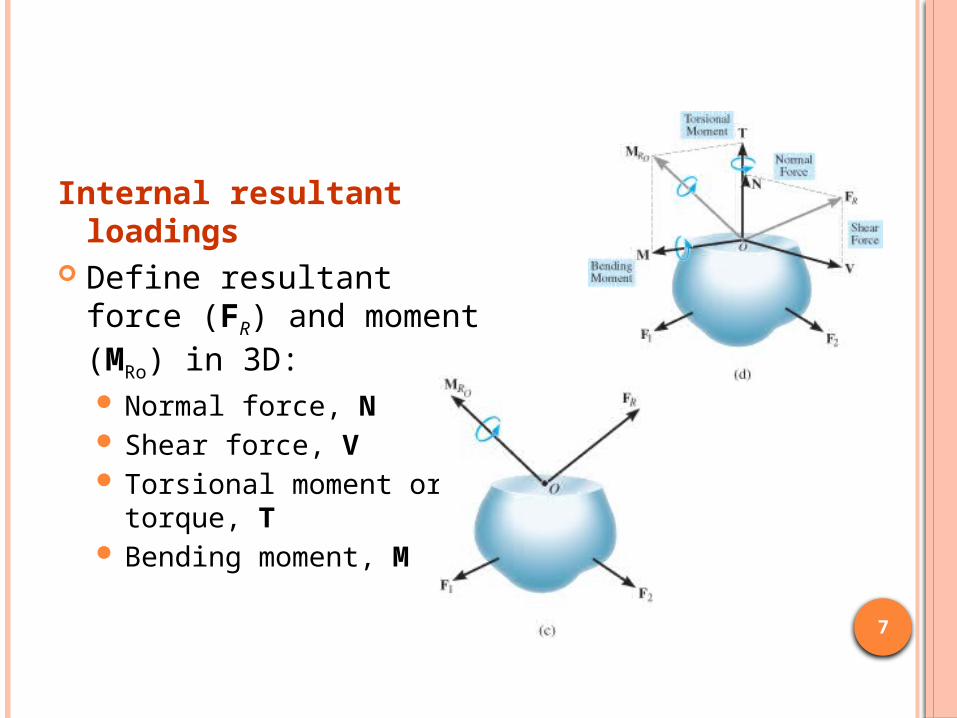
Internal resultant loadings
Define resultant force (FR) and moment (MRo) in 3D: Normal force, N Shear force, V Torsional moment or
torque, T Bending moment, M
8
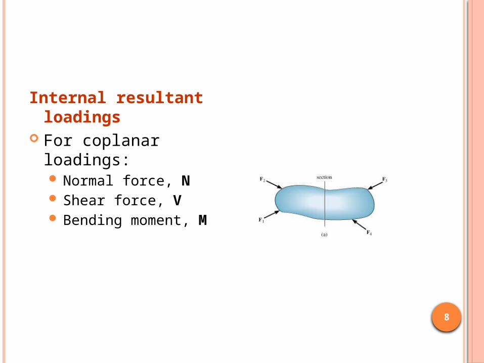
Internal resultant loadings
For coplanar loadings: Normal force, N Shear force, V Bending moment, M
9
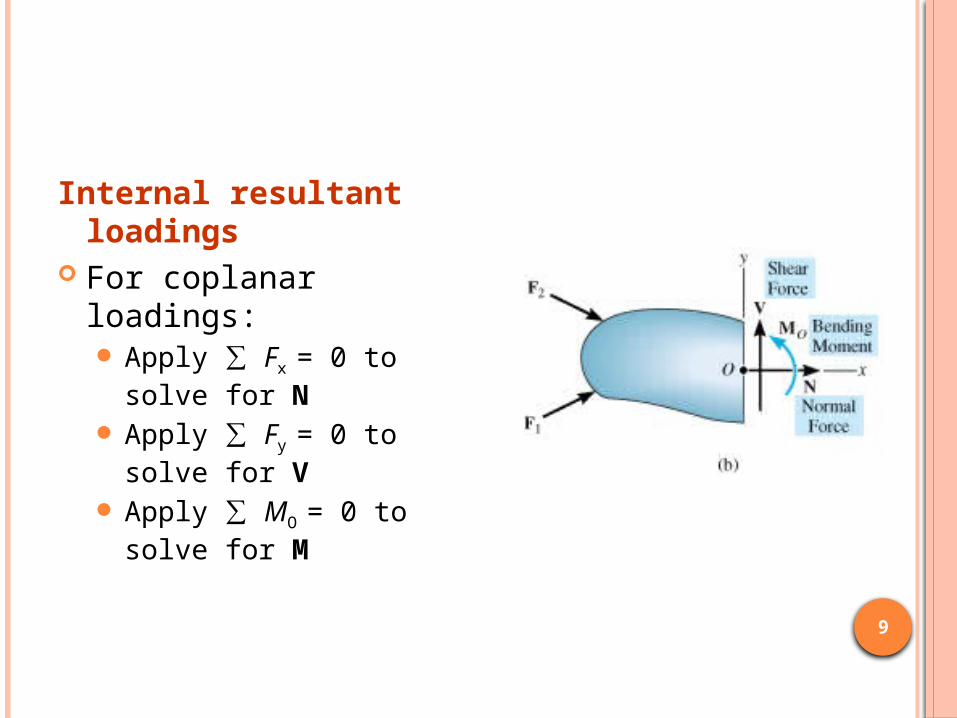
Internal resultant loadings
For coplanar loadings: Apply ∑ Fx = 0 to
solve for N Apply ∑ Fy = 0 to
solve for V Apply ∑ MO = 0 to
solve for M

10
Procedure for analysis Free-body diagram
1. Keep all external loadings in exact locations before “sectioning”
2. Indicate unknown resultants, N, V, M, and T at the section, normally at centroid C of sectioned area
3. Coplanar system of forces only include N, V, and M
4. Establish x, y, z coordinate axes with origin at centroid
11
Procedure for analysis Equations of equilibrium
1. Sum moments at section, about each coordinate axes where resultants act
2. This will eliminate unknown forces N and V, with direct solution for M (and T)
3. Resultant force with negative value implies that assumed direction is opposite to that shown on free-body diagram

12
DETERMINE RESULTANT LOADINGS ACTING ON CROSS SECTION AT C OF BEAM.

13
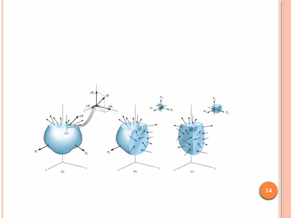
Concept of stress To obtain distribution of force acting over a
sectioned area Assumptions of material:
1. It is continuous (uniform distribution of matter)2. It is cohesive (all portions are connected
together)
Concept of stress Consider ΔA in figure below Small finite force, ΔF acts on ΔA As ΔA → 0, Δ F → 0 But stress (ΔF / ΔA) → finite limit (∞)
14

15
NORMAL STRESSINTENSITY OF FORCE, OR FORCE PER UNIT AREA, ACTING NORMAL TO ΔASYMBOL USED FOR NORMAL STRESS, IS Σ (SIGMA)
Tensile stress: normal force “pulls” or “stretches” the area element ΔA Compressive stress: normal force “pushes” or “ compresses” area element ΔA

16
General state of stress Figure shows the state of
stress acting around a chosen point in a body
Units (SI system) Newtons per square
meter (N/m2) or a pascal (1 Pa = 1 N/m2)
kPa = 103 N/m2 (kilo-pascal)
MPa = 106 N/m2 (mega-pascal)
GPa = 109 N/m2 (giga-pascal)

17
1.4 AVERAGE NORMAL STRESS IN AXIALLY LOADED BAR
Examples of axially loaded bar Usually long and slender structural members Truss members, hangers, bolts Prismatic means all the cross sections are the
same

18
1.4 AVERAGE NORMAL STRESS IN AXIALLY LOADED BAR
σ = average normal stress at any point on cross sectional areaP = internal resultant normal forceA = x-sectional area of the bar
19
Procedure for analysisAverage normal stress Use equation of σ = P/A for x-sectional
area of a member when section subjected to internal resultant force P

20
1.5 AVERAGE SHEAR STRESS
Shear stress is the stress component that act in the plane of the sectioned area.
Consider a force F acting to the bar For rigid supports, and F is large enough, bar
will deform and fail along the planes identified by AB and CD
Free-body diagram indicates that shear force, V = F/2 be applied at both sections to ensure equilibrium

21
Average shear stress over each section is:
τavg = V/A
τavg = average shear stress at section, assumed to be same at each pt on the section
V = internal resultant shear force at section determined from equations of equilibrium
A = area of section
22
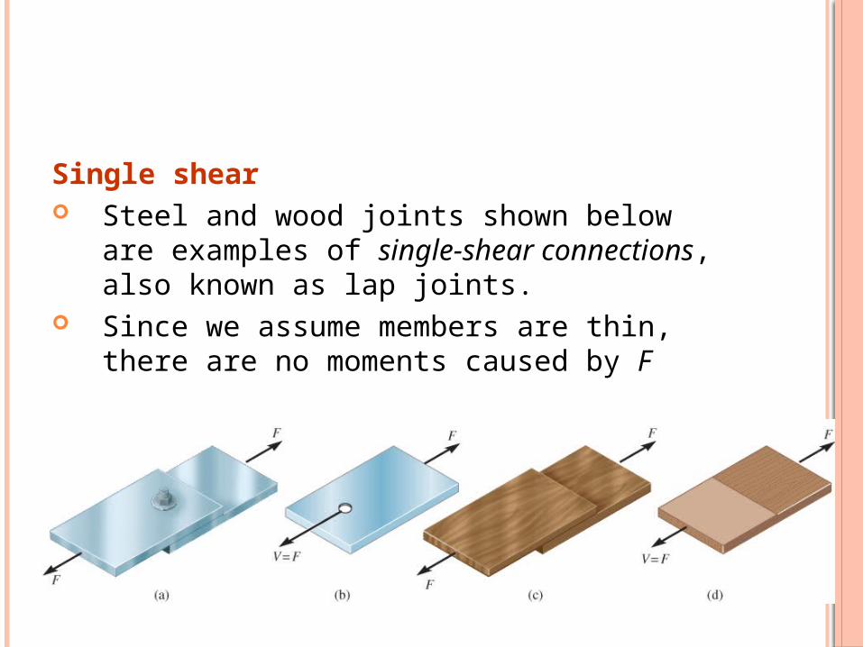
Single shear Steel and wood joints shown below are
examples of single-shear connections, also known as lap joints.
Since we assume members are thin, there are no moments caused by F

23
Procedure for analysisInternal shear1. Section member at the pt where the τavg is
to be determined2. Draw free-body diagram3. Calculate the internal shear force VAverage shear stress4. Determine sectioned area A5. Compute average shear stress τavg = V/A EXAMPLES

24
1.6 ALLOWABLE STRESS When designing a structural member or
mechanical element, the stress in it must be restricted to safe level
Choose an allowable load that is less than the load the member can fully support
One method used is the factor of safety (F.S.)
F.S.=Ffail /Fallow
25
1.6 ALLOWABLE STRESS
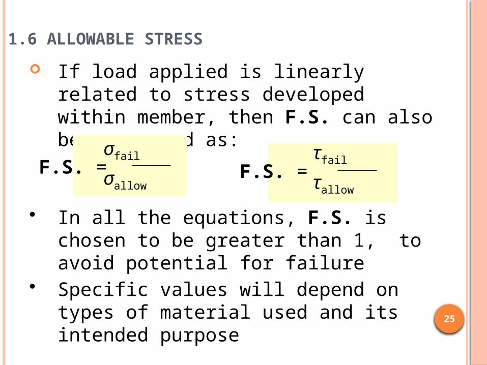
If load applied is linearly related to stress developed within member, then F.S. can also be expressed as:
F.S. = σfail
σallowF.S. =
τfail
τallow
• In all the equations, F.S. is chosen to be greater than 1, to avoid potential for failure
• Specific values will depend on types of material used and its intended purpose
26
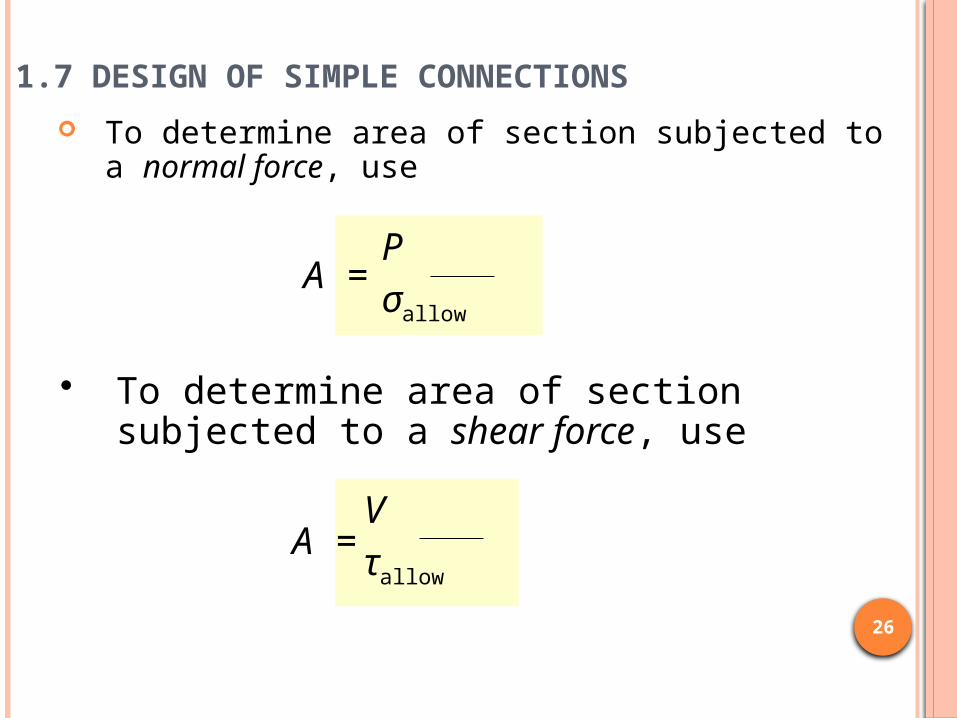
1.7 DESIGN OF SIMPLE CONNECTIONS
To determine area of section subjected to a normal force, use
A = P
σallow
A = V
τallow
• To determine area of section subjected to a shear force, use

27
1.7 DESIGN OF SIMPLE CONNECTIONS
Cross-sectional area of a tension member
Condition: The force has a line of action that passes through the centroid of the x-section.

28
1.7 DESIGN OF SIMPLE CONNECTIONS
Cross-sectional area of a connecter subjected to shear
Assumption: If bolt is loose or clamping force of bolt is unknown, assume frictional force between plates to be negligible.

29
Assumptions: 1. (σb)allow of concrete <
(σb)allow of base plate
2. Bearing stress is uniformly distributed between plate and concrete
1.7 DESIGN OF SIMPLE CONNECTIONS
Required area to resist bearing Bearing stress is normal stress produced
by the compression of one surface against another.
30
1.7 DESIGN OF SIMPLE CONNECTIONS
Procedure for analysisWhen using average normal stress and shear stress equations, consider first the section over which the critical stress is actingInternal loading
1. Section member through x-sectional area2. Draw a free-body diagram of segment of member3. Use equations of equilibrium to determine internal
resultant force

31
1.7 DESIGN OF SIMPLE CONNECTIONS
Procedure for analysisRequired area Based on known allowable stress,
calculate required area needed to sustain load from A = P/τallow or A = V/τallow

32
EXAMPLE 1.13
The two members pinned together at B. If the pins have an allowable shear stress of τallow = 90 MPa, and allowable tensile stress of rod CB is (σt)allow = 115 MPa
Determine to nearest mm the smallest diameter of pins A and B and the diameter of rod CB necessary to support the load.

33
EXAMPLE 1.13 (SOLN)
Draw free-body diagram:
σ = P
A
800 N
(0.04 m)(0.04 m) = 500 kPa =
No shear stress on section, since shear force at section is zero
τavg = 0
34
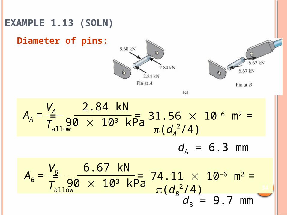
EXAMPLE 1.13 (SOLN)
Diameter of pins:
dA = 6.3 mm
AA =VA
Tallow
2.84 kN
90 103 kPa = = 31.56 10−6 m2 = (dA2/4)
dB = 9.7 mm
AB =VB
Tallow
6.67 kN
90 103 kPa = = 74.11 10−6 m2 = (dB
2/4)

35
EXAMPLE 1.13 (SOLN)
Diameter of pins:
dA = 7 mm dB = 10 mm
Choose a size larger to nearest millimeter.
36
CHAPTER REVIEW Assumptions for a uniform normal
stress distribution over x-section of member (σ = P/A)
1. Member made from homogeneous isotropic material
2. Subjected to a series of external axial loads that,3. The loads must pass through centroid of x-
section

37
CHAPTER REVIEW Determine average shear stress by
using τ = V/A equation V is the resultant shear force on x-sectional area A Formula is used mostly to find average shear
stress in fasteners or in parts for connections

38
CHAPTER REVIEW Design of any simple connection
requires that Average stress along any x-section not exceed a
factor of safety (F.S.) or Allowable value of σallow or τallow
These values are reported in codes or standards and are deemed safe on basis of experiments or through experience