c f' f' - xa.yimg.comxa.yimg.com/kq/groups/21948400/641165467/name/qt-22... · method...
TRANSCRIPT

~~ ~W, ->,Jl....:tC f' f'
BAUER INTERNATIONAL FZE
METHOD STATEMENT
AND
CONTIGUOUS PILE WALL DESIGN
PROJECT HEART OF DOHA, PHASE-1A, QATAR
CLIENT DOHA LAND Co.
PROJECT MANAGER TURNER
DESIGN CONSULTANT ARUP CONSULTANTS
CONSULTANT BURNS & McDONNELL
Roji John Engineering Manager
~d£J. August 24, 2009
24/0809 Issue 1 Rev.O MS/RW/SP/080/QT-22 QT-22-CPW
INTEGRATED MANAGEMENT SYSTEM
EN 150 9001 : 2000 EN 150 14001 : 2004 OHSAS 18001 : 1999 Bauer International FZE, P.O. Box 43673, Abu Dhabi, United Arab Emirates Reg No 04 100 031238 Reg. No 04 104 031238Tel: ++971-2-6721405, Fax: ++971-2-6725594 Reg No. 04 116031238
~ ~ BAUER INTERNATIONAL QATAR
AMENDMENT RECORD SHEET
Section No. Rev. No.
Amendment Details Date of Issue
Prepared By
Checked By
Issued By
00 Issued for approval 24.08.09 RJ Du RJ
Page A
23/08/2004 Issue 1 Rev.O F/PD/EXJ362 QT-22-CPW
- 3
LIST OF CONTENTS PAGE NO.
1.0 CONTIGUOUS PILE WALL - INTRODUCTION 4
2.0 METHOD STATEMENT 5
2.1 CONTIGUOUS PILE WALL 5-8
2.2 INSTALLATION OF ANCHORS 9-14
3.0 DESIGN OF CONTIGUOUS PILE WALL 15
3.1 COMPUTER ANALYSIS 16 -41
3.2 LONGITUDINAL REINFORCEMENT 42
3.2.1 LONGITUDINAL REINFORCEMENT ENVELOPE 43
3.3 SHEAR REINFORCEMENT 44-45
3.4 DESIGN OF ANCHORS 46 -47
4.0 DESIGN OF CAPPING BEAM UNDER ANCHORS 48
4.1 ANALYSIS 48
4.2 MAIN REINFORCEMENT 49
4.3 SHEAR REINFORCEMENT 50 - 51
APPENDIX
- DESIGN CHART
- DESIGN CHART CAPPING BEAM
24/08/09 Issue 1 Rev.O MS/RW/SP/080/QT-22

-4
1.0 INTRODUCTION
A contiguous pile wall is to be constructed as shoring system around the
existing Heritage Building to avoid any influence to the building due to
excavation and construction of basement for Doha Project.
In accordance with the soil and site requirements, the design is made for a
contiguous pile wall of 900 mm diameter and pile centre to centre at 950 mm,
stabilized by tie-back ground anchors.
24/08/09 Issue 1 Rev.O MS/RW/SP/080/QT-22
... ,,_. ~,' '. -'g.~ •••. ,..,
-5- ., ': <,c, t, E,':•.. :., :
2.0 METHOD STATEMENT
2.1.1 EQUIPMENT
We intend to use rotary drilling rjgs type BAUER BG22 or BG25, which
rotate casings by rotary power head into the ground. These machines are
specially developed to produce minimum disturbance of the surrounding soil,
and hence, enable them to work in close proximity to existing structures.
2.1.2 WORKING PLATFORM
The working platform shall be firm, levelled and dry. The secant piling works
will be carried out from a working platform at the existing ground.
2.1.3 SURVEY WORKS
A qualified surveyor will carryout setting out and surveying works. The
surveyor shall transfer the demarcation points to minimum 2 points at each
corner point. The plot line, building line and the shoring line shall be
established. Facilities shall be provided to the Engineer for checking the
points.
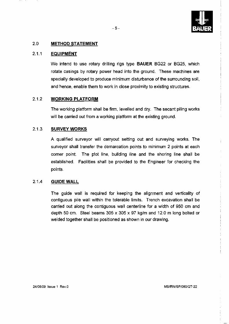
2.1.4 GUIDE WALL
The guide wall is required for keeping the alignment and verticality of
contiguous pile wall within the tolerable limits. Trench excavation shall be
carried out along the contiguous wall centerline for a width of 950 cm and
depth 50 cm. Steel beams 305 x 305 x 97 kg/m and 12.0 m long bolted or
welded together shall be positioned as shown in our drawing.
24/08/09 Issue 1 Rev.O MS/RW/SP/080/QT-22
DETAILS OF GUIDE WALL FOR CONTIGUOUS PILE WALL
17 CONNECTING WELDED PLA TE 200mm x 10mm THK 14Nos.14 Nos. NAILING BARS TO THE
950
38002850
12000
3800
950
GROUND FOR HOLDING H-BEAM (BOTH SIDE) GUIDE WALL BEAM-305x305x91kg/m
3800
115
-'=;,,,,,,_T""""""::'=----::=-____,=-.",;.",--,.--=~-==:____=",.......,~;"""_____","""=____::=_____,=__,___.",,:;,,,,...L - ~_/
I I \
""T""'r::-~r-----""f=-----''=='--~---!--=~-=:::''''-~~--=:''''__---=""'''''---:::''l='''_----'~-'-~:::''- ...... /
I~ GUIDE WALL BEAM-305x305x91kg/m WELDED TO OTHER GUIDE WALL BEAM WITH WELDED PLA TE 200mm x 10mm THK
GUIDE WALL-PLAN VIEW
CONNECTION WELDED PLATE 200mm x10mm THK 950
BUTT WELDGUIDE WALL 6mm THK.
GUIDE WALL BEAM- 305x305x91kg/m WELDED TO OTHER GUIDE WALL BEAM WITH WELDED PLA TE 200mm x 10mm THK
GUIDE WALL BEAM305x305x91kg/m
WORKING PLATE FORM
4 Nos. NAILING BARS TO THE GROUND FOR HOLDING H-BEAM (BOTH SIDE) CONTIGUOUS PILE
900 DIA. OF PILE
SECTION Z-Z
- 6
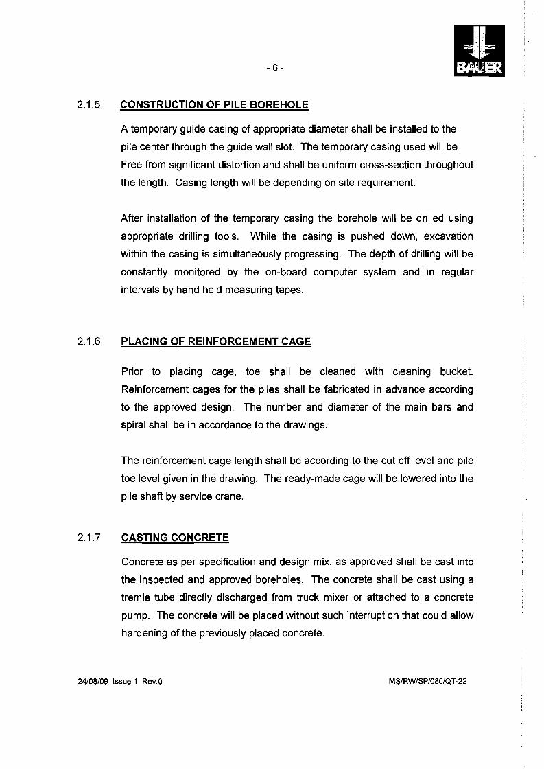
2.1.5 CONSTRUCTION OF PILE BOREHOLE
A temporary guide casing of appropriate diameter shall be installed to the
pile center through the guide wall slot. The temporary casing used will be
Free from significant distortion and shall be uniform cross-section throughout
the length. Casing length will be depending on site requirement.
After installation of the temporary casing the borehole will be drilled using
appropriate drilling tools. While the casing is pushed down, excavation
within the casing is simultaneously progressing. The depth of drilling will be
constantly monitored by the on-board computer system and in regular
intervals by hand held measuring tapes.
2.1.6 PLACING OF REINFORCEMENT CAGE
Prior to placing cage, toe shall be cleaned with cleaning bucket.
Reinforcement cages for the piles shall be fabricated in advance according
to the approved design. The number and diameter of the main bars and
spiral shall be in accordance to the drawings.
The reinforcement cage length shall be according to the cut off level and pile
toe level given in the drawing. The ready-made cage will be lowered into the
pile shaft by service crane.
2.1.7 CASTING CONCRETE
Concrete as per specification and design mix, as approved shall be cast into
the inspected and approved boreholes. The concrete shall be cast using a
tremie tube directly discharged from truck mixer or attached to a concrete
pump. The concrete will be placed without such interruption that could allow
hardening of the previously placed concrete.
24/08/09 Issue 1 Rev.O MS/RW/SP/080IQT-22
-7
The tremie will be gradually withdrawn as the concreting proceeds ensuring
that the bottom 2 - 3 meters of the tremie always remains within the
previously placed concrete.
The excessive concrete above the cut-off level shall be chipped before
capping beam construction.
After completion of concreting, the temporary casing will be withdrawn by
drilling rig. When the casing is being extracted, a sufficient quantity of
concrete shall be maintained within it to ensure that pressure from external
water, or soil is exceeded and that the pile is neither reduced in section nor
contaminated.
During the course of casing extraction, the concrete level within a temporary
casing shall be topped up when found necessary.
2.1.8 DISPOSAL OF DRILLING SPOIL
Spoil from drilling of boreholes will be stored on site and carted away at
regular intervals.
2.1.9 DAILY PILING REPORTS
Piling report will be prepared on daily basis and will be submitted to the
Engineer for approval.
2.1.10 CAPPING BEAM
Capping beam will be constructed as per the design requirement after
removing the contaminated concrete from the pile head.
24/08/09 Issue 1 Rev.O MS/RW/SP/080/QT-22
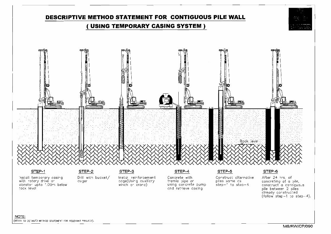
DESCRIPTIVE METHOD STATEMENT FOR CONTIGUOUS PILE WALL
( USING TEMPORARY CASING SYSTEM)
I~
<l~f.'i Ir~\ ''ll~D
~
liili~ ~
Jt1:i
i~La
STEP-1 STEP-2 STEP-3 STEP-4 STEP-5 STEP-6
Install temporary casing with rotary drive or vibrator upto 1.00m below rock level
Drill with auger
bucket! Install reinforcement cage(Using auxiliary winch or crane)
Con crete with tremie pipe or using concrete pump and retrieve casing
Construct alternative piles same as step-1 to step-4
After 24 hrs. of concreting of a pile, construct a contiguous pile between 2 piles already constructed (follow step-1 to step-4).
NOTE: (REFER TO DETAILED METHOD STATEMENT FOR RELEVANT PROJECT).
MS/RW/CP/090
- 8
2.1.11 EXCAVATION
After the installation of the shoring system the excavation to be carried out
as per the approved method statement. The dewatering to be carried out to
keep the excavation platform level free of water.
2.1.12 DEWATERING
The dewatering to be carried out as per the approved method statement to
lower the water table upto required designed level.
24/08/09 Issue 1 Rev.O MS/RW/SP/080/QT-22
-9
2.2 INSTALLATION OF ANCHORS
In the following describes in principle the main steps of construction and major technical aspects.
The anchoring works comprise:
• drilling of bore-holes by rotary drilling
• supply and mixing of cement mortar
• supply and installation of ground anchor tendons
• grouting and if necessary post-grouting of bore-holes
• tensioning of anchors
• supply and installation of anchor heads
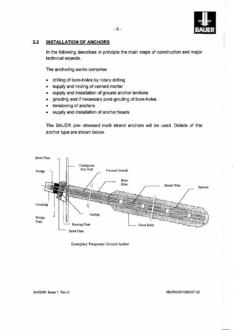
The BAUER pre- stressed multi strand anchors will be used. Details of this
anchor type are shown below.
Bowl Plate
Contiguous
Wedge Pile Wall Covered Strands
Covering
Wedge Plate
Sealing
Bearing Plate
Bore Hole
Grout Body
Strand Wire Spacers
Bowl Plate
Exemplary Temporary Ground Anchor
24/08/09 Issue 1 Rev.O MS/RW/SP/080/QT-22
- 10 III 2.2.1 Drilling and Anchor Tendon Installation
Any coring or drilling work shall be performed from a dry and stabile working
platform. Before drilling by anchor drilling rig the holes will be pre-cored by the
anchor drilling rig through the piles till the last 10cm of the pile concrete.
Drill bits shall be suitable to drill through soil consisting of Sand and Sandstone
as per relevant soil report. The drill bits are attached to drill strings of certain
diameter required for the anchor tendon installation. Drilling will be supported
by water l~ushing technique. In case soil conditions as mentioned above are
differing 'from those encountered adjustment of tooling, 'flushing technique as
well as of parameters of anchorage might be required.
After reaching the final depth the anchor tendon will be installed through the
drill string. The drill bit will be stroke off (Iost-drill-bit-system) by pushing the
anchor tendon together with support of a hammering device applying
hammering forces onto the drill string.
2.2.2 Grouting When final drilling depth is reached and the tendon is installed, cement grout is
pumped through the openings of the drill bit while raising the rods, filling the
bore-hole from bottom to top and replacing the water which was used for the
drilling process.
After this grout has set, post-grouting of the bond length might be required
through the extra grouting tube attached to the tendon depending on the actual
encountered soil condition. This post-grouting will enhance the bonding
capacity of the grout! ground interface.
24/08/09 Issue 1 Rev.O MS/RW/SP/080/QT-22
- 11
2.2.3 Cement Grout
The cement grout mix design will be as follows:
- cement grout mixture (per batch): 2 bags cement = 100 kg
55 liters water = 55 kg*
(* 55 to 80 Iitres of sweet water depends on the ambient temperature)
- W/C ratio = 0.55
- Design compressive strength of the grout at 28 days = 25 N/mm2
The equipment used for grout mixture:
BAUER ZMI grout mixer
BAUER KP60 pressure pump
24/08/09 Issue 1 Rev.O MS/RW/SP/080/QT-22
- 12
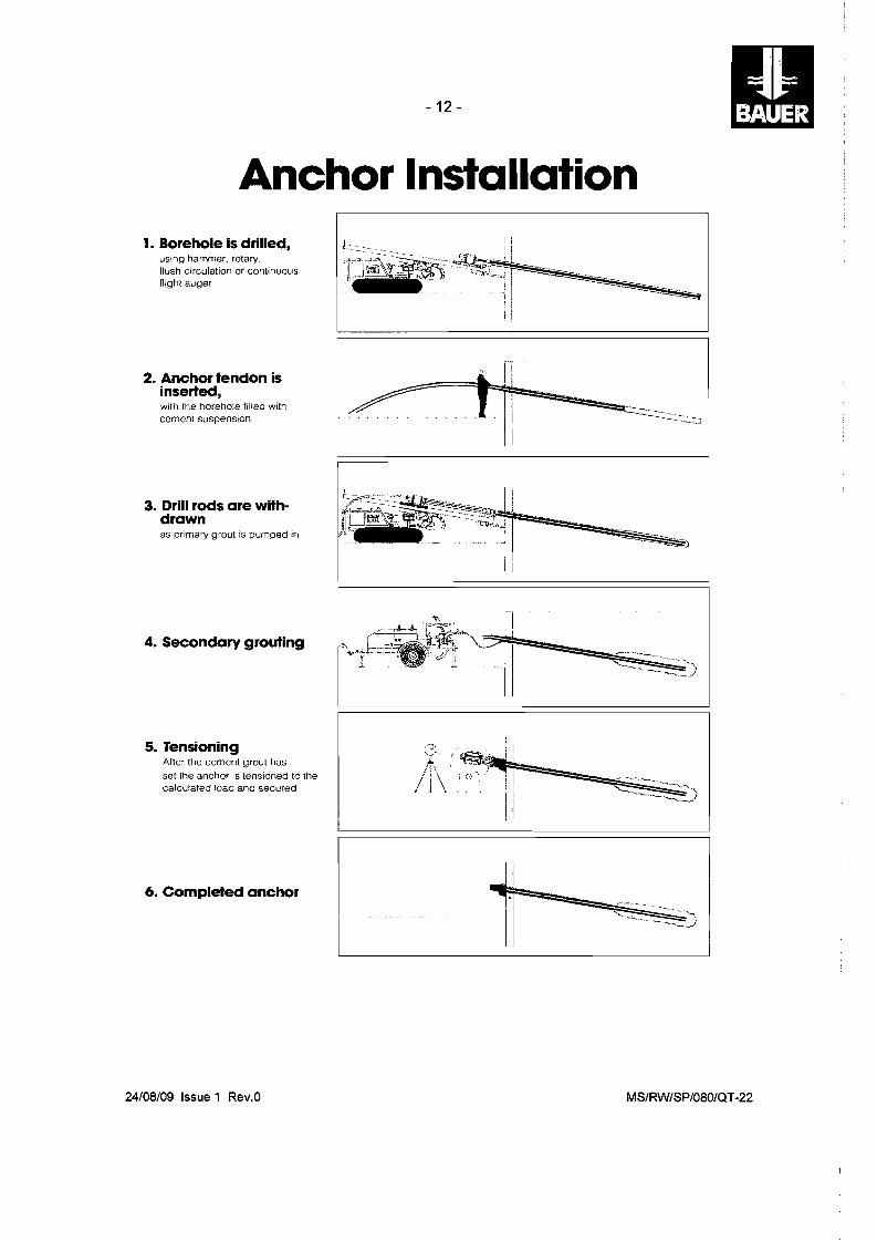
Anchor Installation 1. Borehole is drilled,
using hammer. rotary. flush circulation or continuous flight auger
2. Anchor tendon is inserted, with the borehole filled with cement suspension
3. Drill rods are withdrawn as primary grout is pumped in
4. Secondary grouting
5. Tensioning After the cement grout has set the anchor is tensioned to the calculated load and secured
6. Completed anchor
'" [!
~==tt~~4::::-~:::::::::::::::_::_ ..:::;
I
24/08/09 Issue 1 Rev.O MS/RW/SP/080/QT-22
-13
2.2.4 Anchor Stressing
After having finalized the anchor post grouting, 7 days later the anchor will be tested and locked. For this a hydraulic jack HOP82 will be installed over the exposed anchor and pulling of the overall anchor until required design load progresses.
The load stages are:
Loading 75% of working load
Loading 100% of working load
Loading 125% of working load
Locking 80% of working load, considering an active movement of the wall
After the testing and stressing procedure, the anchor wedge plate with wedges are fixed/coupled with the anchor. By this a constant pulling force in the anchor will avoid the deflection of the wall.
2.2.5 Records
The following information shall be provided for each anchor installation:
Date, time, location, anchor type, drilling and installation procedures.
Details of drilling including drill hole diameter and length, method of drilling,
peculiarities during drilling, type of drill bit and method of flushing the hole.
The results of all tensioning shall be recorded on BAUER control forms.
24/08/09 Issue 1 Rev.O MS/RW/SP/080/QT-22
-14
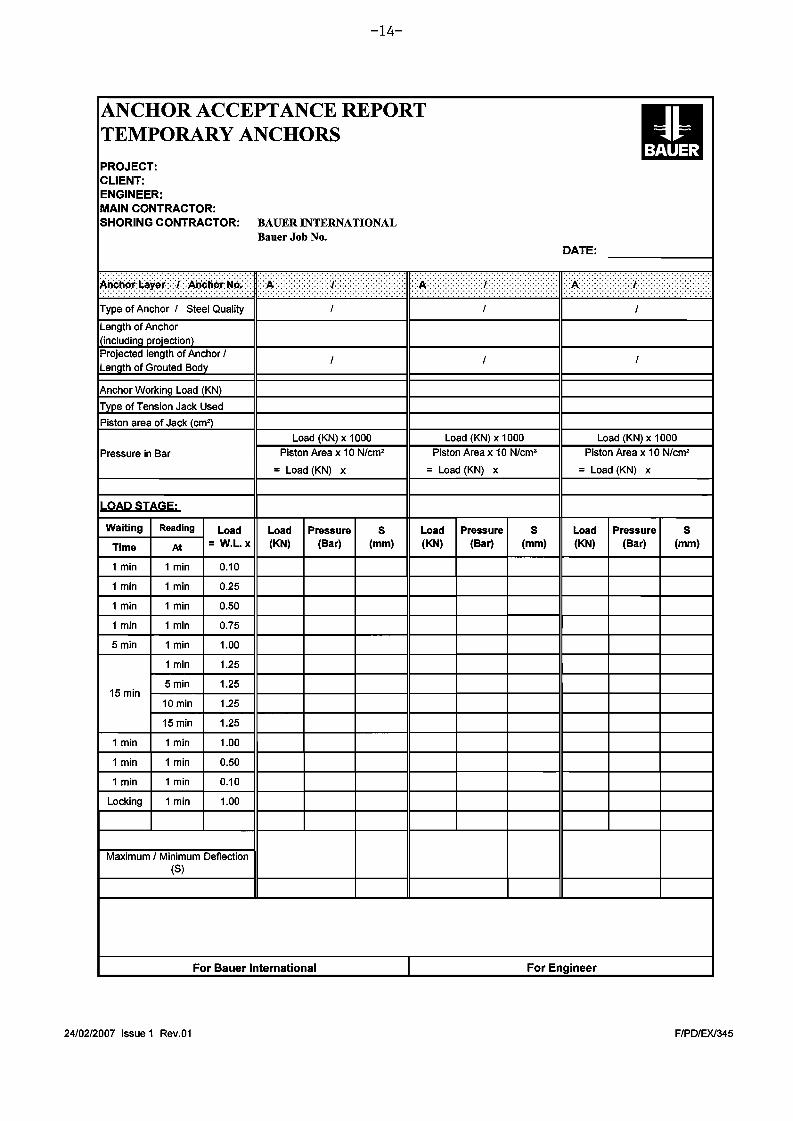
ANCHOR ACCEPTANCE REPORT TEMPORARY ANCHORS
PRO.IECT: CLIENT: ENGINEER: MAIN CONTRACTOR: SHORING CONTRACTOR:
..............................
Type of Anchor 1 Steel Quality
Length of Anchor including projection}
Projected length of Anchor 1 Length of Grouted Body
Anchor Working Load (KN)
Type of Tension Jack Used
Piston area of Jack (em')
Pressure in Bar
LOAD STAGE:
BAUER INTERNATIONAL Bauer Job No.
DATE:
.............................................................................." ' .
.
Load (KN) x 1000 Load (KN) x 1000 Load (KN) x 1000
Piston Area x 10 N/cm' Piston Area x 10 N/cm' Piston Area x 10 N/cm'
= Load (KN) x = Load (KN) x = Load (KN) x
Waiting
Time
1 min
1 min
1 min
1 min
5min
15 min
1 min
1 min
1 min
Locking
Reading Load
At = W.L. x
1 min 0.10
1 min 0.25
1 min 0.50
1 min 0.75
1 min 1.00
1 min 1.25
5min 1.25
10 min 1.25
15 min 1.25
1 min 1.00
1 min 0.50
1 min 0.10
1 min 1.00
Maximum 1Minimum Deflection (S)
Load (KN)
Pressure (Bar)
S (mm)
Load (KN)
Pressure (Bar)
S (mm)
Load (KN)
Pressure (Bar)
S (mm)
For Bauer International For Engineer
24/02/2007 Issue 1 Rev.01 F/PDIEXl345
- 15
3.0 DESIGN FOR CONTIGUOUS PILE WALL
3.1 COMPUTER ANALYSIS
(Maximum Excavation Depth -4.70 QND)
24/08/09 Issue 1 Rev.O MS/RW/SP/080/QT-22
- 16
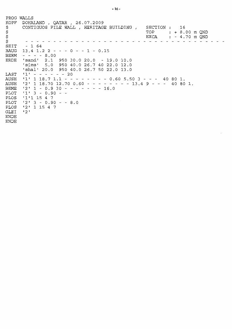
PROG KOPF $ $ $ $ SEIT BAUG BERM ERDE
LAST AUSH AUSH BEME PLOT PLOS PLOT PLOS GLEI ENDE ENDE
WALLS DOHALAND QATAR 26.07.20091 1
1 1CONTIGUOS PILE WALL HERITAGE BUILDING SECTION 16 TOP + 8.00 m QND EXCA - 4.70 m QND
- 1 64 13.4 1.2 2 - - - 0 - - 1 - 0.15 - - - - 8.00 'sand' 2.1 950 30.0 20.0 - 19.0 10.0 'sims' 5.0 950 40.0 26.7 40 22.0 12.0 'shall 20.0 950 40.0 26.7 50 22.0 13.0 'I' - - - - - - 20 'I' 1 18.7 1.1 - - - - - - - - 0.60 5.50 3 - - - 40 80 1. '2 1 1 18.70 12.70 0.60 - - - - - - - - 13.4 9 - - - 40 80 1. '2' 1 - 0.9 30 - - - - - 16.0 'I' 3 - 0.90 - '1'1 15 4 7 '2' 3 - 0.90 - - 8.0 '2' 1 15 4 7 '2 '
- 17
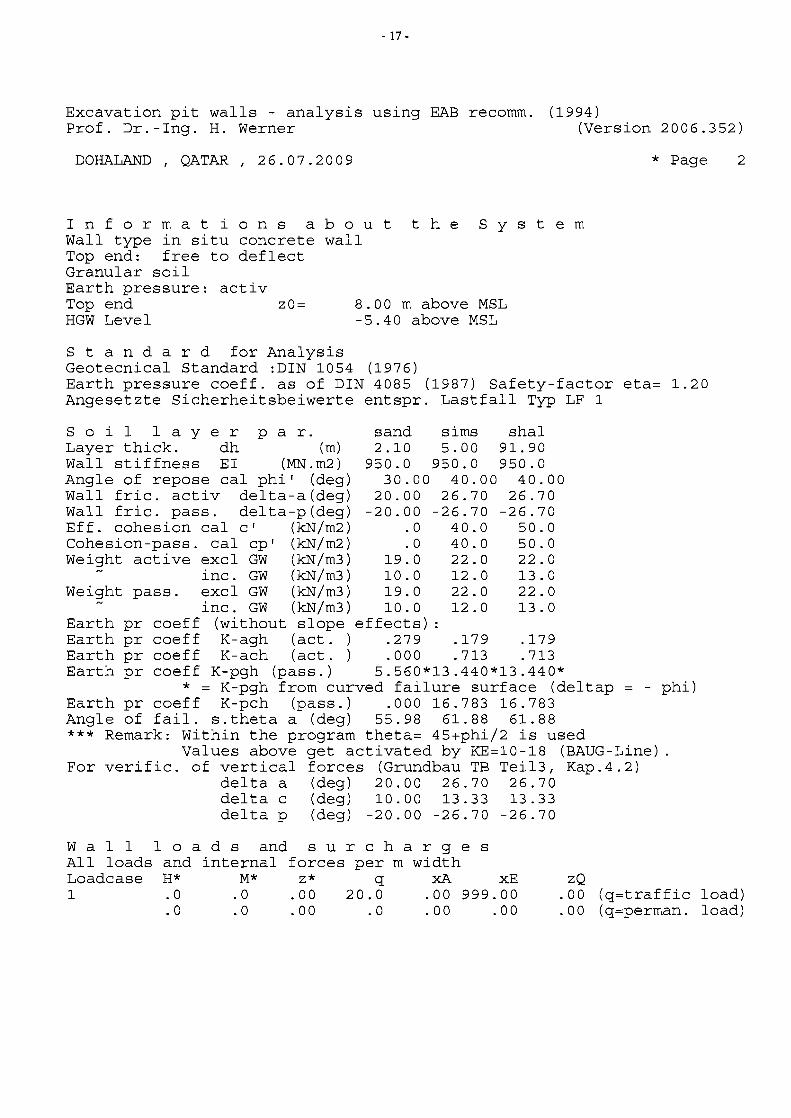
Excavation pit walls - analysis using EAB recomm. (1994) Prof. Dr.-Ing. H. Werner (Version 2006.352)
DOHALAND , QATAR, 26.07.2009 * Page 2
I n for mat ion s abo u t the S Y s t e m Wall type in situ concrete wall Top end: free to deflect Granular soil Earth pressure: activ Top end zO= 8.00 m above MSL HGW Level -5.40 above MSL
S tan dar d for Analysis Geotecnical Standard :DIN 1054 (1976) Earth pressure coeff. as of DIN 4085 (1987) Safety-factor eta= 1.20 Angesetzte Sicherheitsbeiwerte entspr. Lastfall Typ LF 1
S 0 ill aye r par. sand sims shal Layer thick. dh (m) 2.10 5.00 91.90 Wall stiffness EI (MN.m2) 950.0 950.0 950.0 Angle of repose cal phi' (deg) 30.00 40.00 40.00 Wall fric. activ delta-a (deg) 20.00 26.70 26.70 Wall fric. pass. delta-p(deg) -20.00 -26.70 -26.70 Eff. cohesion cal c' (kN/m2) .0 40.0 50.0 Cohesion-pass. cal cp I (kN/m2) .0 40.0 50.0 Weight active excl GW (kN/m3) 19.0 22.0 22.0
inc. GW (kN/m3) 10.0 12.0 13.0 Weight pass. excl GW (kN/m3) 19.0 22.0 22.0
inc. GW (kN/m3) 10.0 12.0 13.0 Earth pr coeff (without slope effects) : Earth pr coeff K-agh (act.) .279 .179 .179 Earth pr coeff K-ach (act.) .000 .713 .713 Earth pr coeff K-pgh (pass.) 5.560*13.440*13.440*
* = K-pgh from curved failure surface (del tap - phi) Earth pr coeff K-pch (pass.) .000 16.783 16.783 Angle of fail. s.theta a (deg) 55.98 61.88 61.88 *** Remark: Within the program theta= 45+phi/2 is used
Values above get activated by KE=10-18 (BAUG-Line). For verific. of vertical forces (Grundbau TB Tei13, Kap.4.2)
delta a (deg) 20.00 26.70 26.70 delta c (deg) 10.00 13.33 13.33 delta p (deg) -20.00 -26.70 -26.70
W all loa d s and sur c h a r 9 e s All loads and internal forces per m width Loadcase H* M* z* q xA xE zQ 1 .0.0 .00 20.0 .00 999.00 .00 (q=traffic load)
. 0 .0 .00 .0 .00 .00 .00 (q=perman. load)
- 18
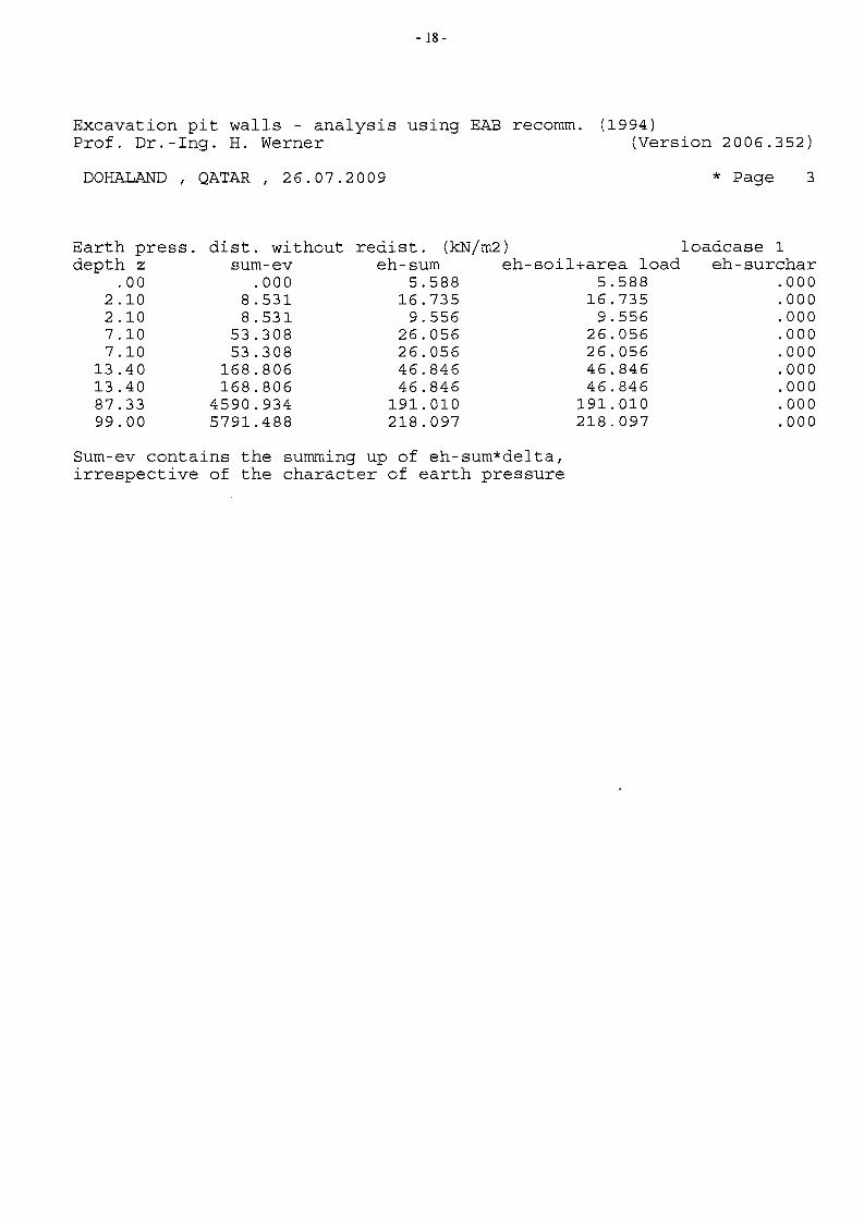
Excavation pit walls - analysis using EAB recomm. (1994) Prof. Dr.-Ing. H. Werner (Version 2006.352)
DOHALAND , QATAR, 26.07.2009 * Page 3
Earth press. dist. without redist. (kN/m2) loadcase 1 depth z sum-ev eh-sum eh-soil+area load eh-surchar
.00 .000 5.588 5.588 .000 2.10 8.531 16.735 16.735 .000 2.10 8.531 9.556 9.556 .000 7.10 53.308 26.056 26.056 .000 7.10 53.308 26.056 26.056 .000
13.40 168.806 46.846 46.846 .000 13.40 168.806 46.846 46.846 .000 87.33 4590.934 191.010 191.010 .000 99.00 5791.488 218.097 218.097 .000
Sum-ev contains the summing up of eh-sum*delta, irrespective of the character of earth pressure

- 19
Excavation pit walls - analysis using EAB recomm. (1994 ) Prof. Dr.-lng. H. Werner (Version 2006.352)
DOHALAND / QATAR / 26.07.2009 * Page 4
Excv-Nr. 1/ Foot end free / E-figure 3 Depth z is related to NN Wall fully cantilevering
*** Warning: ZW is higher then ZGW Description of E-figure:
Earth pressure does not get changed. Elast.support t(m) c(N/cm3)
All. (eres) Depth z
(m) 1. 238 1.500 2.000 2.500 3.000 3.500 4.000 4.500 5.000 5.500 6.000 6.500 7.000 7.500 8.000 8.500 9.000 9.500
10.000 10.500 11.000 11.500 12.000 12.500
.00 40. 1.00 80.
and calc. (ecalc) bedding eres
(kN/m2) .000
21.663 63.026
859.921 981.471
1103.021 1224.571 1346.121 1467.671 1589.221 1654.771 1720.321 1785.871 1995.761 2066.911 2138.061 2209.210 2280.361 2351.510 2422.660 2493.811 2564.960 2636.110 2707.260
ecalc (kN/m2)
.000 11.193 11.908
9.311 6.321 3.518
.821 -1.870 -4.657 -7.635
-10.872 -14.403 -18.232 -22.340 -26.690 -31.232 -35.909 -40.654 -45.399 -50.069 -54.591 -58.887 -62.886 -66.519
tension given-e
(MN/m3) 45.525 56.000 76.000 80.000 80.000 80.000 80.000 80.000 80.000 80.000 80.000 80.000 80.000 80.000 80.000 80.000 80.000 80.000 80.000 80.000 80.000 80.000 80.000 80.000
with bedded foot reduced c
(MN/m3 ) .000
56.000 76.000 80.000 80.000 80.000 80.000 80.000 80.000 80.000 80.000 80.000 80.000 80.000 80.000 80.000 80.000 80.000 80.000 80.000 80.000 80.000 80.000 80.000
spr.const (MN/m)
.000 21. 332 38.000 40.000 40.000 40.000 40.000 40.000 40.000 40.000 40.000 40.000 40.000 40.000 40.000 40.000 40.000 40.000 40.000 40.000 40.000 40.000 40.000 40.000
5
- 20
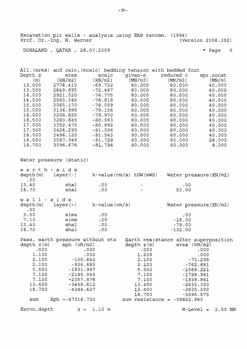
Excavation pit walls - analysis using EAB recomm. (1994) Prof. Dr.-lng. H. Werner (Version 2006.352)
DOHALAND QATAR 26.07.2009 * PageI I
All. (eres) and calc. (ecalc) bedding tension with bedded foot Depth z eres ecalc given-e reduced c spr.const
(m) (kN/m2 ) (kN/m2) (MN/m3 ) (MN/m3) (MN/m) 13.000 2778.410 -69.732 80.000 80.000 40.000 13.500 2849.695 -72.487 80.000 80.000 40.000 14.000 2921.520 -74.775 80.000 80.000 40.000 14.500 2993.345 -76.618 80.000 80.000 40.000 15.000 3065.170 -78.059 80.000 80.000 40.000 15.500 3136.995 -79.156 80.000 80.000 40.000 16.000 3208.820 -79.970 80.000 80.000 40.000 16.500 3280.645 -80.563 80.000 80.000 40.000 17.000 3352.470 -80.992 80.000 80.000 40.000 17.500 3424.295 -81.306 80.000 80.000 40.000 18.000 3496.120 -81.543 80.000 80.000 40.000 18.500 3567.945 -81.728 80.000 80.000 28.000 18.700 3596.676 -81.794 80.000 80.000 8.000
Water pressure (static)
ear t h - sid e depth (m) layer (-) k-value(cm/s) hGW(mWS) Water pressure (KN/m2)
.00 13.40 shal .00 .00 18.70 shal .00 53.00
w all sid e depth (m) layer (-) k-value(cm/s) Water pressure (KN/m2)
.00 5.50 sims .00 .00 7.10 sims .00 -16.00
13.40 shal .00 -79.00 18.70 shal .00 -132.00
Pass. earth pressure without eta Earth resistance after superposition depth z (m) eph (kN/m2) depth z (m) eres (kN/m2)
.000 .000 .000 .000 1.100 .000 1. 238 .000 2.100 -105.640 2.100 -71.298 2.100 -926.685 2.100 -762.681 5.500 -1931.997 5.500 -1589.221 7.100 -2190.045 7.100 -1798.981 7.100 -2357.876 7.100 -1938.841
13.400 -3458.612 13.400 -2835.330 18.700 -4384.627 13.400 -2835.330
18.700 -3596.675 sum Eph =-47316.730 sum resistance -38822.980
Excvn.depth z = 1.10 m W-Level 2.50 NN
6
- 21
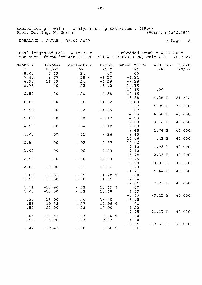
Excavation pit walls - analysis using EAB recomm. (1994 ) Prof. Dr.-Ing. H. Werner (Version 2006.352)
DOHALAND , QATAR, 26.07.2009 * Page
Total length of wall = 18.70 m Embedded depth t = 17.60 m Foot supp. force for eta = 1.20 all.A = 38823.0 kN, calc.A = 20.2 kN
depth z H-press deflection b-mom. shear force A-H spr. const m kN/m2 mm kN.m kN kN kN/mm 8.00 5.59 .34 .00 .00 7.40 8.77 .28 * -1.20 -4.31 6.90 11.43 .24 -4.56 -9.36 6.76 .00 .22 -5.92 -10.15
-10.15 .00 6.50 .00 .20 -8.58 -10.15
-5.88 4.26 B 21.332 6.00 .00 .16 -11.52 -5.88
.07 5.95 B 38.000 5.50 .00 .12 -11.49 .07
4.73 4.66 B 40.000 5.00 .00 .08 -9.12 4.73
7.89 3.16 B 40.000 4.50 .00 .04 -5.18 7.89
9.65 1.76 B 40.000 4.00 .00 .01 -.36 9.65
10.06 .41 B 40.000 3.50 .00 -.02 4.67 10.06
9.12 -.93 B 40.000 3.00 .00 -.06 9.23 9.12
6.79 -2.33 B 40.000 2.50 .00 -.10 12.63 6.79
2.98 -3.82 B 40.000 2.00 -5.00 -.14 14.32 4.23
-1. 21 -5.44 B 40.000 1. 80 -7.01 -.15 14.20 M .00 1. 50 -10.00 -.18 14.55 2.54
-4.66 -7.20 B 40.000 1.11 -13.90 -.22 13.59 M .00 1. 00 -15.00 -.23 13.68 1. 59
-7.53 -9.12 B 40.000 .90 -16.00 -.24 13.00 -5.98 .56 -19.38 -.27 11. 96 M .00 .50 -20.00 -.28 12.00 1. 22
-9.95 -11.17 B 40.000 .05 -24.47 -.33 9.70 M .00 .00 -25.00 -.33 9.73 1. 30
-12.04 -13.34 B 40.000 -.44 -29.43 -.38 7.00 M .00
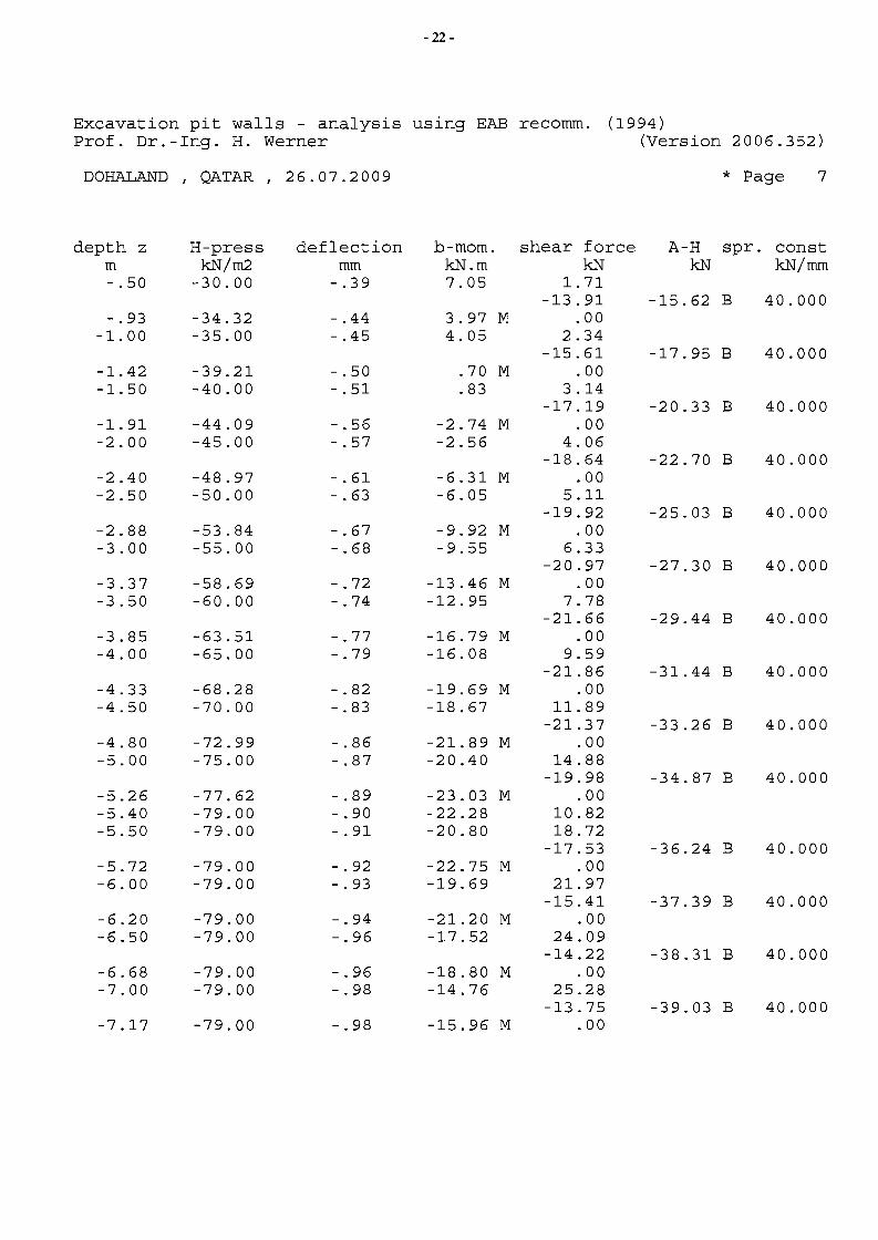
- 22
Excavation pit walls - analysis using EAB recomm. (1994) Prof. Dr.-lng. H. Werner (Version 2006.352)
DOHALAND I QATAR I 26.07.2009 * Page 7
depth z H-press deflection b-mom. shear force A-H spr. const m kN/m2 mm kN.m kN kN kN/mm -.50 -30.00 -.39 7.05 1. 71
-13.91 -15.62 B 40.000 -.93 -34.32 -.44 3.97 M .00
-1.00 -35.00 -.45 4.05 2.34 -15.61 -17.95 B 40.000
-1. 42 -39.21 -.50 .70 M .00 -1.50 -40.00 -.51 .83 3.14
-17.19 -20.33 B 40.000 -1.91 -44.09 -.56 -2.74 M .00 -2.00 -45.00 -.57 -2.56 4.06
-18.64 -22.70 B 40.000 -2.40 -48.97 -.61 -6.31 M .00 -2.50 -50.00 -.63 -6.05 5.11
-19.92 -25.03 B 40.000 -2.88 -53.84 -.67 -9.92 M .00 -3.00 -55.00 -.68 -9.55 6.33
-20.97 -27.30 B 40.000 -3.37 -58.69 -.72 -13.46 M .00 -3.50 -60.00 -.74 -12.95 7.78
-21.66 -29.44 B 40.000 -3.85 -63.51 -.77 -16.79 M .00 -4.00 -65.00 -.79 -16.08 9.59
-21.86 -31.44 B 40.000 -4.33 -68.28 -.82 -19.69 M .00 -4.50 -70.00 -.83 -18.67 11.89
-21.37 -33.26 B 40.000 -4.80 -72.99 -.86 -21.89 M .00 -5.00 -75.00 -.87 -20.40 14.88
-19.98 -34.87 B 40.000 -5.26 -77.62 -.89 -23.03 M .00 -5.40 -79.00 -.90 -22.28 10.82 -5.50 -79.00 -.91 -20.80 18.72
-17.53 -36.24 B 40.000 -5.72 -79.00 -.92 -22.75 M .00 -6.00 -79.00 -.93 -19.69 21.97
-15.41 -37.39 B 40.000 -6.20 -79.00 -.94 -21.20 M .00 -6.50 -79.00 -.96 -17.52 24.09
-14.22 -38.31 B 40.000 -6.68 -79.00 -.96 -18.80 M .00 -7.00 -79.00 -.98 -14.76 25.28
-13.75 -39.03 B 40.000 -7.17 -79.00 -.98 -15.96 M .00
8
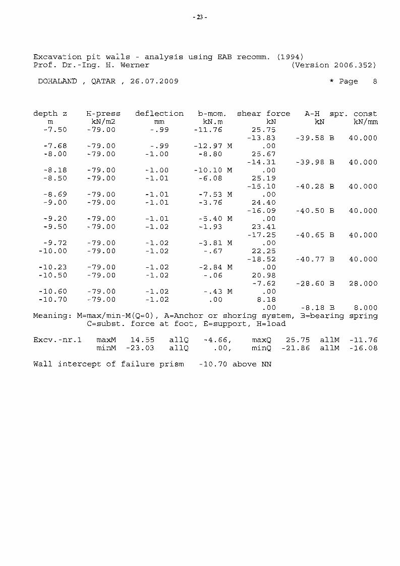
- 23
Excavation pit walls - analysis using EAB recomm. (1994) Prof. Dr.-Ing. H. Werner (Version 2006.352)
DOHALAND , QATAR, 26.07.2009 * Page
depth z H-press deflection b-mom. shear force A-H spr. const m kN/m2 mm kN.m kN kN kN/mm
-7.50 -79.00 -.99 -11.76 25.75 -13.83 -39.58 B 40.000
-7.68 -79.00 -.99 -12.97 M .00 -8.00 -79.00 -1.00 -8.80 25.67
-14.31 -39.98 B 40.000 -8.18 -79.00 -1.00 -10.10 M .00 -8.50 -79.00 -1.01 -6.08 25.19
-15.10 -40.28 B 40.000 -8.69 -79.00 -1.01 -7.53 M .00 -9.00 -79.00 -1.01 -3.76 24.40
-16.09 -40.50 B 40.000 -9.20 -79.00 -1.01 -5.40 M .00 -9.50 -79.00 -1.02 -1. 93 23.41
-17.25 -40.65 B 40.000 -9.72 -79.00 -1.02 -3.81 M .00
-10.00 -79.00 -1.02 -.67 22.25 -18.52 -40.77 B 40.000
-10.23 -79.00 -1.02 -2.84 M .00 -10.50 -79.00 -1.02 -.06 20.98
-7.62 -28.60 B 28.000 -10.60 -79.00 -1.02 -.43 M .00 -10.70 -79.00 -1.02 .00 8.18
.00 -8.18 B 8.000 Meaning: M=max/min-M(Q=O) , A=Anchor or shoring system, B=bearing spring
C=subst. force at foot, E=support, H=load
Excv.-nr.1 maxM 14.55 allQ -4.66, maxQ 25.75 allM -11.76 minM -23.03 allQ . 00, minQ -21.86 allM -16.08
Wall intercept of failure prism -10.70 above NN
9
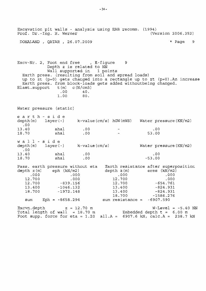
- 24
Excavation pit walls - analysis using EAB recomm. (1994) Prof. Dr.-lng. H. Werner (Version 2006.352)
DOHALAND , QATAR, 26.07.2009 * Page
Excv-Nr. 2, Foot end free , E-figure 9 Depth z is related to NN Wall supported in 1 points
Earth press. (resulting from soil and spread loads) up to zt (p=O) gets changed into a rectangle up to zt (p=O) .An increase Earth press. from block-loads gets added withoutbeing changed.
Elast.support t(m) c(N/cm3) .00 40.
1.00 80.
Water pressure (static)
ear t depth(m)
.00 13.40 18.70
h - sid e layer(-)
shal shal
k-value(cm/s)
.00
.00
hGW(mWS) Water pressure (KN/m2)
.00 53.00
w a I I sid e depth (m) layer(-) k-value(cm/s) Water pressure (KN/m2)
.00 13.40 shal .00 .00 18.70 shal .00 -53.00
Pass. earth pressure without eta Earth resistance after superposition depth z (m) eph (kN/m2) depth z (m) eres (kN/m2)
.000 .000 .000 .000 12.700 .000 12.700 .000 12.700 -839.156 12.700 -654.761 13.400 -1046.132 13.400 -824.931 18.700 -1972.148 13.400 -824.931
18.700 -1586.276 sum Eph = -8658.294 sum resistance -6907.590
Excvn.depth z = 12.70 m W-Level = -5.40 NN Total length of wall = 18.70 m Embedded depth t = 6.00 m Foot supp. force for eta = 1.20 all.A 6907.6 kN, calc.A = 238.7 kN
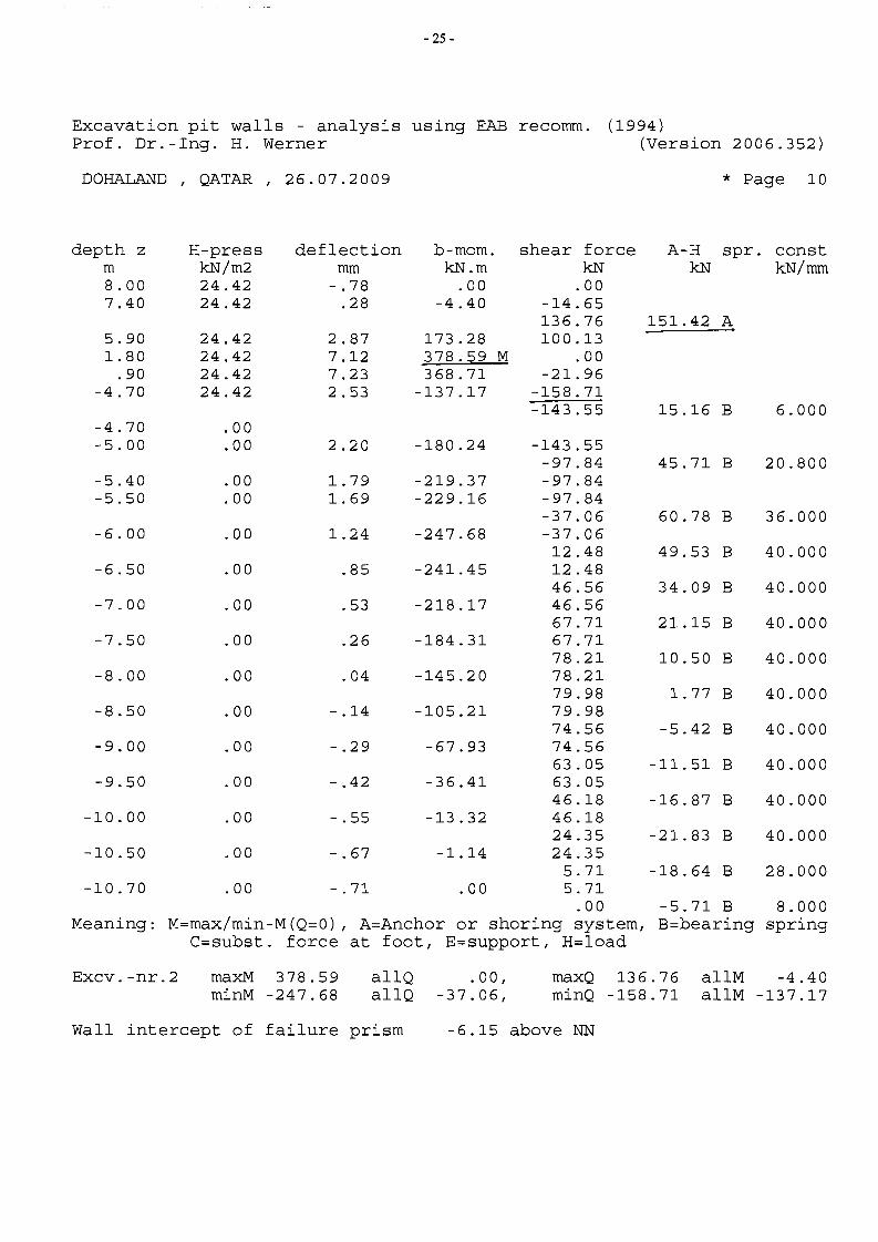
- 25
Excavation pit walls - analysis using EAB recomm. (1994) Prof. Dr.-Ing. H. Werner (Version 2006.352)
DOHALAND , QATAR, 26.07.2009 * Page 10
depth z H-press deflection b-mom. shear force A-H spr. const m kN/m2 mm kN.m kN kN kN/mm 8.00 24.42 -.78 .00 .00 7.40 24.42 .28 -4.40 -14.65
136.76 151. 42 A 5.90 24.42 2.87 173.28 100.13 1. 80 24.42 7.12 378.59 M .00
.90 24.42 7.23 368.71 -21.96 -4.70 24.42 2.53 -137.17 -158.71
-143.55 15.16 B 6.000 -4.70 .00 -5.00 .00 2.20 -180.24 -143.55
-97.84 45.71 B 20.800 -5.40 .00 1. 79 -219.37 -97.84 -5.50 .00 1. 69 -229.16 -97.84
-37.06 60.78 B 36.000 -6.00 .00 1.24 -247.68 -37.06
12.48 49.53 B 40.000 -6.50 .00 .85 -241. 45 12.48
46.56 34.09 B 40.000 -7.00 .00 .53 -218.17 46.56
67.71 21.15 B 40.000 -7.50 .00 .26 -184.31 67.71
78.21 10.50 B 40.000 -8.00 .00 .04 -145.20 78.21
79.98 1. 77 B 40.000 -8.50 .00 -.14 -105.21 79.98
74.56 -5.42 B 40.000 -9.00 .00 -.29 -67.93 74.56
63.05 -11.51 B 40.000 -9.50 .00 -.42 -36.41 63.05
46.18 -16.87 B 40.000 -10.00 .00 -.55 -13.32 46.18
24.35 -21.83 B 40.000 -10.50 .00 -.67 -1.14 24.35
5.71 -18.64 B 28.000 -10.70 .00 -.71 .00 5.71
.00 -5.71 B 8.000 Meaning: M=max/min-M(Q=O) , A=Anchor or shoring system, B=bearing spring
C=subst. force at foot, E=support, H=load
Excv. -nr. 2 maxM 378.59 allQ .00, maxQ 136.76 allM -4.40 minM -247.68 allQ -37.06, minQ -158.71 allM -137.17
Wall intercept of failure prism -6.15 above NN
- 26
Excavation pit walls - analysis using EAB recomm. (1994) Prof. Dr.-lng. H. Werner (Version 2006.352)
DOHALAND QATAR 26.07.2009 * Page 11I I
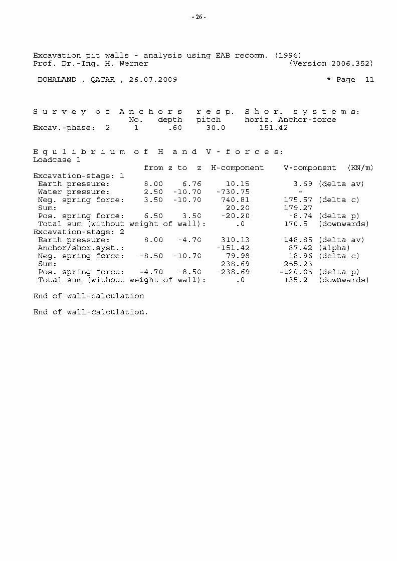
Sur v e y 0 fAn c h 0 r s res p. S h 0 r. s y s tern s: No. depth pitch horiz. Anchor-force
Excav.-phase: 2 1 .60 30.0 151.42
E q u 1 i b r i u m 0 f Han d V - for c e s: Loadcase 1
from z to z H-component V-component (KN/m) Excavation-stage: 1 Earth pressure: 8.00 6.76 10.15 3.69 (delta av) Water pressure: 2.50 -10.70 -730.75 Neg. spring force: 3.50 -10.70 740.81 175.57 (delta c) Sum: 20.20 179.27 Pos. spring force: 6.50 3.50 -20.20 -8.74 (delta p) Total sum (without weight of wall) : . 0 170.5 (downwards)
Excavation-stage: 2 Earth pressure: 8.00 -4.70 310.13 148.85 (delta av) Anchor/shor.syst. : -151.42 87.42 (alpha) Neg. spring force: -8.50 -10.70 79.98 18.96 (delta c) Sum: 238.69 255.23 Pos. spring force: -4.70 -8.50 -238.69 -120.05 (delta p) Total sum (without weight of wall) : . 0 135.2 (downwards)
End of wall-calculation
End of wall-calculation.
- 27
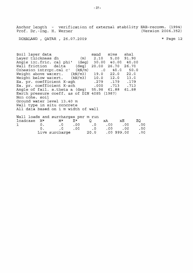
Anchor length verification of external stability EAB-recomm. (1994) Prof. Dr.-Ing. H. Werner (Version 2006.352)
DOHALAND QATAR 26.07.2009 * Page 12I I
Soil layer data sand sims shal Layer thickness dh (m) 2.10 5.00 91.90 Angle int.fric. cal phi' (deg) 30.00 40.00 40.00 Wall friction delta (deg) 20.00 26.70 26.70 Cohesion intrcpt.cal c' (kN/m) .0 40.0 50.0 Weight above watert. (kN/m3) 19.0 22.0 22.0 Weight below watert. (kN/m3) 10.0 12.0 13.0 Ea. pro coefficient K-agh .279 .179 .179 Ea. pro coefficient K-ach .000 .713 .713 Angle of fail. s.theta a (deg) 55.98 61.88 61.88 Earth pressure coeff. as of DIN 4085 (1987) Non cohe. soil Ground water level 13.40 m Wall type in situ concrete All data based on 1 m width of wall
Wall loads and surcharges per m run loadcase H* M* Z* Q xA xE ZQ 1 o. .0 .00 . 0 .00 .00 .00
o. . 0 .00 . 0 .00 .00 .00 Live surcharge 20.0 .00 999.00 .00
- 28
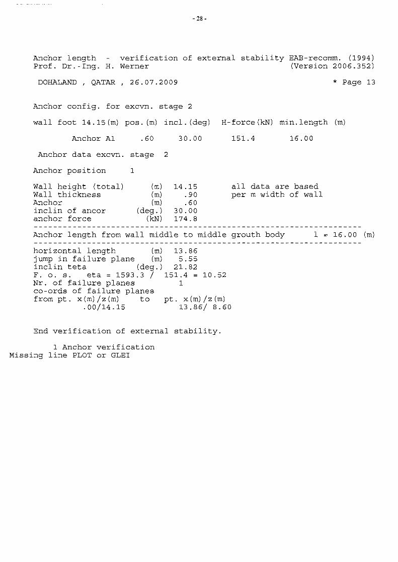
Anchor length verification of external stability EAB-recomm. (1994) Prof. Dr.-Ing. H. Werner (Version 2006.352)
DOHALAND QATAR 26.07.2009 * Page 13f f
Anchor config. for excvn. stage 2
wall foot 14.15(m) pos. (m) incl. (deg) H-force(kN) min.length (m)
Anchor Al .60 30.00 151.4 16.00
Anchor data excvn. stage 2
Anchor position 1
Wall height (total) (m) 14.15 all data are based Wall thickness (m) .90 per m width of wall Anchor (m) .60 inclin of ancor (deg. ) 30.00 anchor force (kN) 174.8
Anchor length from wall middle to middle grouth body 1 = 16.00 (m)
horizontal length (m) 13.86 jump in failure plane (m) 5.55 inclin teta (deg.) 21.82 F. o. s. eta = 1593.3 / 151.4 10.52 Nr. of failure planes 1 co-ords of failure planes from pt. x(m)/z(m) to pt. x (m) / z (m)
.00/14.15 13.86/ 8.60
End verification of external stability.
1 Anchor verification Missing line PLOT or GLEI
---------
- 29
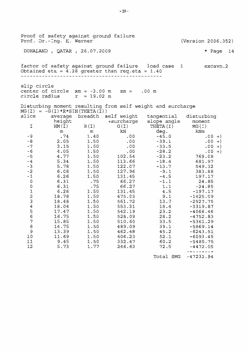
Proof of safety against ground failure Prof. Dr.-Ing. H. Werner (Version 2006.352)
DOHALAND QATAR 1 26.07.2009 * Page 141
factor of safety against ground failure load case 1 excavn.2 Obtained eta = 4.28 greater than req.eta = 1.40
slip circle center of circle xm -3.00 m zm .00 m circle radius r = 19.02 m
Disturbing moment resulting from self weight and surcharge MG (I) -G(I)*R*SIN(THETA(I)) slice average breadth self weight tangential disturbing
height +surcharge slope angle moment I HM (I) B (I) G (I) THETA (I) MG (I)
m m kN deg. kNm -9 .74 1.40 .00 -45.0 .00 +) -8 2.05 1. 50 .00 -39.1 .00 +) -7 3.15 1. 50 .00 -33.5 .00 +) -6 4.05 1.50 .00 -28.2 .00 +) -5 4.77 1. 50 102.54 -23.2 769.08 -4 5.34 1. 50 113.66 -18.4 681.97 -3 5.78 1. 50 122.07 -13.7 549.32 -2 6.08 1. 50 127.96 -9.1 383.88 -1 6.26 1. 50 131. 45 -4.5 197.17
0 6.31 .75 66.27 -1.1 24.85 0 6.31 .75 66.27 1.1 -24.85 1 6.26 1. 50 131.45 4.5 -197.17 2 18.78 1. 50 475.03 9.1 -1425.09 3 18.48 1. 50 561.72 13.7 -2527.75 4 18.04 1. 50 553.31 18.4 -3319.87 5 17.47 1. 50 542.19 23.2 -4066.46 6 16.75 1. 50 528.09 28.2 -4752.83 7 15.85 1. 50 510.60 33.5 -5361.29 8 14.75 1. 50 489.09 39.1 -5869.14 9 13.39 1. 50 462.48 45.2 -6243.51
10 11.69 1.50 406.23 52.1 -6093.45 11 9.45 1. 50 332.47 60.2 -5485.75 12 5.73 1. 77 246.63 72.5 -4472.05
Total SMG -47232.94
---------
- 30
Proof of safety against ground failure Prof. Dr. -Ing. H. Werner (Version 2006.352)
DOHALAND QATAR f 26.07.2009 * Page 15f
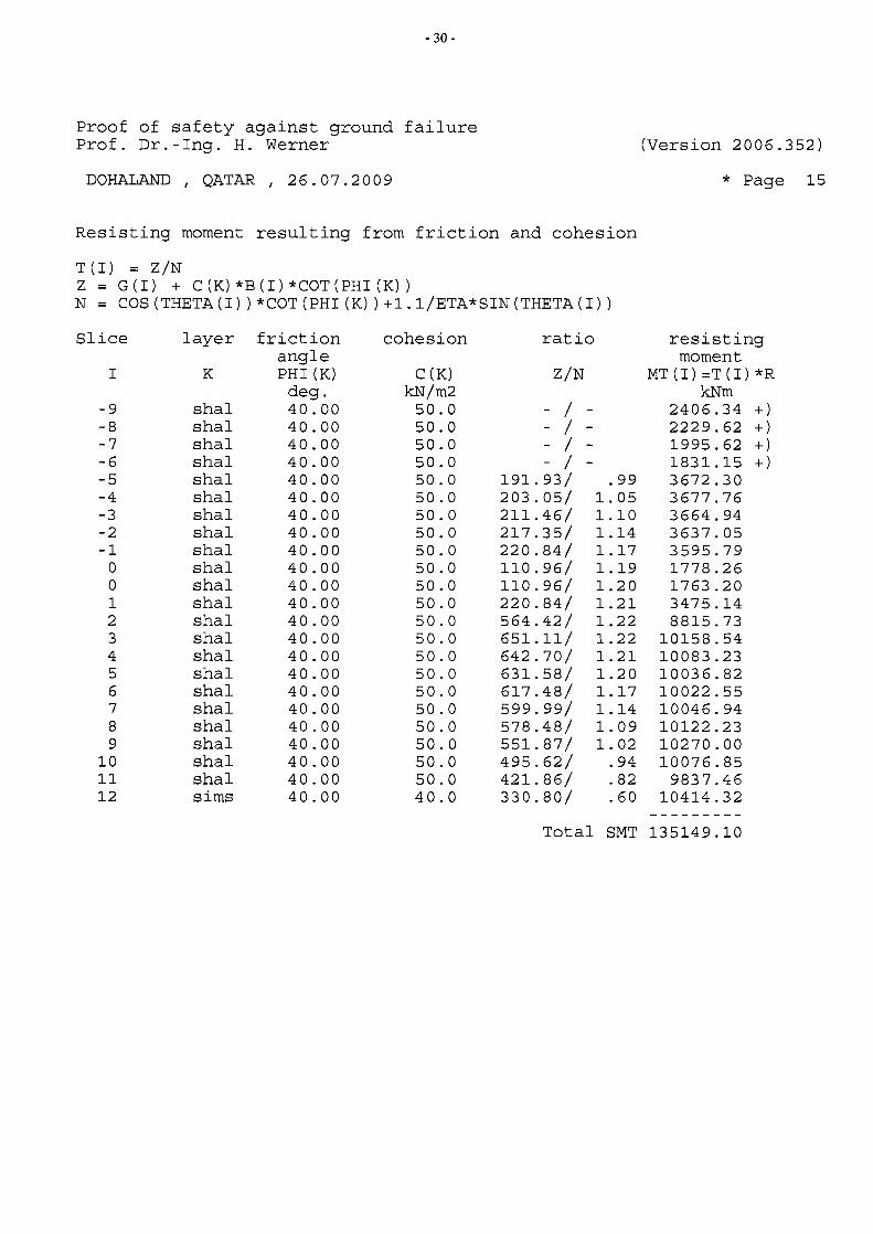
Resisting moment resulting from friction and cohesion
T (I) = Z/N Z = 8(1) + C(K)*B(I)*COT(PHI(K)) N = COS(THETA(I))*COT(PHI(K))+l.l/ETA*SIN(THETA(I))
Slice layer friction cohesion ratio resisting angle moment
I K PHI (K) C (K) Z/N MT(I)=T(I)*R deg. kN/m2 kNm
-9 shal 40.00 50.0 - / - 2406.34 +) -8 shal 40.00 50.0 - / - 2229.62 +) -7 shal 40.00 50.0 - / - 1995.62 +) -6 shal 40.00 50.0 - / - 1831.15 +) -5 shal 40.00 50.0 191.93/ .99 3672.30 -4 shal 40.00 50.0 203.05/ 1. 05 3677.76 -3 shal 40.00 50.0 211.46/ 1.10 3664.94 -2 shal 40.00 50.0 217.35/ 1.14 3637.05 -1 shal 40.00 50.0 220.84/ 1.17 3595.79
0 shal 40.00 50.0 110.96/ 1.19 1778.26 0 shal 40.00 50.0 110.96/ 1.20 1763.20 1 shal 40.00 50.0 220.84/ 1.21 3475.14 2 shal 40.00 50.0 564.42/ 1.22 8815.73 3 shal 40.00 50.0 651.11/ 1.22 10158.54 4 shal 40.00 50.0 642.70/ 1.21 10083.23 5 shal 40.00 50.0 631.58/ 1.20 10036.82 6 shal 40.00 50.0 617.48/ 1.17 10022.55 7 shal 40.00 50.0 599.99/ 1.14 10046.94 8 shal 40.00 50.0 578.48/ 1. 09 10122.23 9 shal 40.00 50.0 551. 87/ 1. 02 10270.00
10 shal 40.00 50.0 495.62/ .94 10076.85 11 shal 40.00 50.0 421.86/ .82 9837.46 12 sims 40.00 40.0 330.80/ .60 10414.32
Total SMT 135149.10
- 31
Proof of safety against ground failure Prof. Dr.-Ing. H. Werner (Version 2006.352)
DOHALAND QATAR 26.07.2009 * Page 16I I
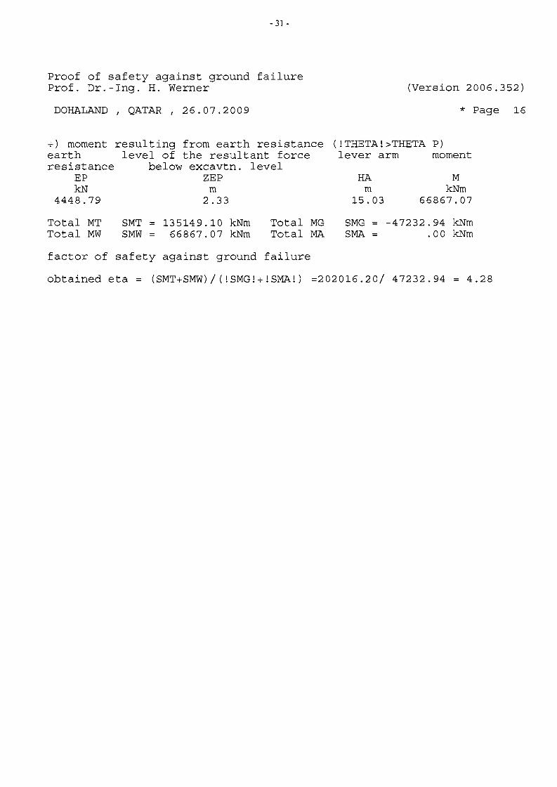
+) moment resulting from earth resistance (ITHETAI>THETA P) earth level of the resultant force lever arm moment resistance below excavtn. level
EP ZEP HA M kN m m kNm
4448.79 2.33 15.03 66867.07
Total MT SMT 135149.10 kNm Total MG SMG -47232.94 kNm Total MW SMW 66867.07 kNm Total MA SMA .00 kNm
factor of safety against ground failure
obtained eta = (SMT+SMW)/(ISMGI+ISMAI) =202016.20/ 47232.94 4.28
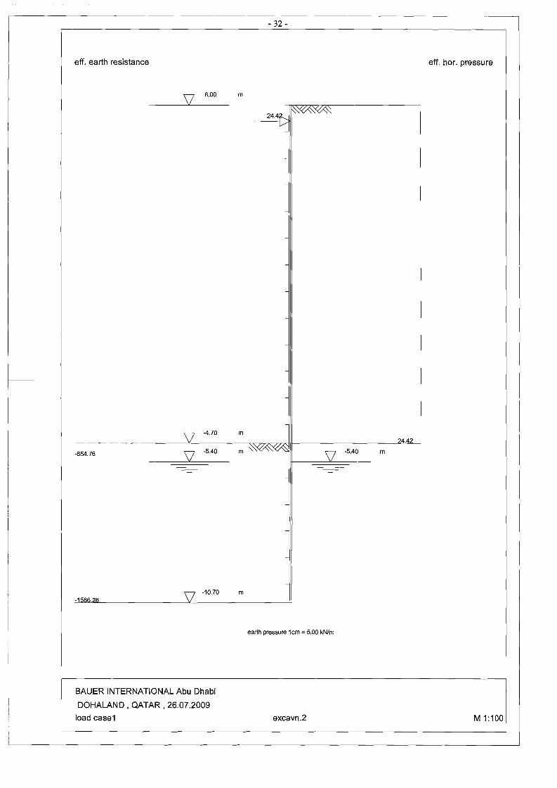
- 32
eff. earth resistance eff. hor. pressure
8.00 m
-
-
-
-
-
-
'\7 -4.70 m \I 74.42- - - - - - --------"------=-:-=-- ~~J1--~-~--==---.JV -5.40 m " 'V,. 'v' '" \l -5.40 m-654.76
-
V m-10.70 -1586.78
earth pressure 1cm =5.00 kN/m
BAUER INTERNATIONAL Abu Dhabi
DOHALAND. QATAR. 26.07.2009
load case1 excavn.2 M1:100
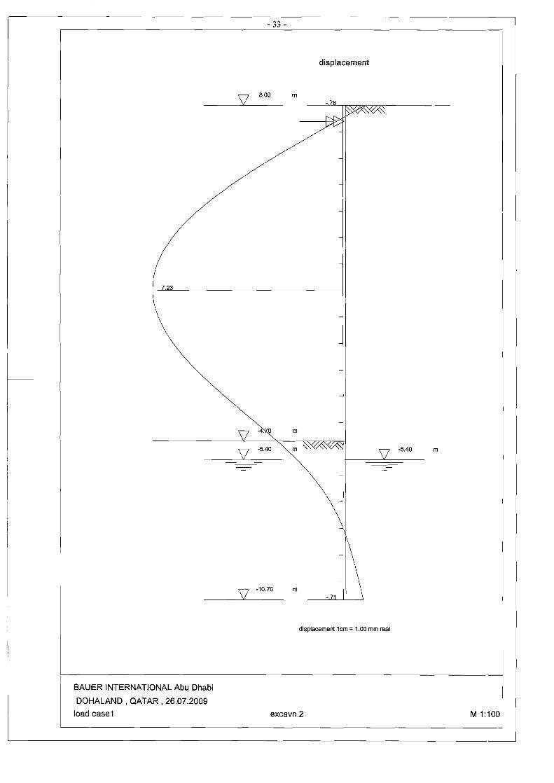
- 33
7.23
displacement
8.00
-10.70
m -.78
m
m '\
m - 71
displacement 1cm =1.00 mm real
-5.40 m
BAUER INTERNATIONAL Abu Dhabi
DOHALAND , QATAR, 26.07.2009
load case1 excavn.2 M 1:100
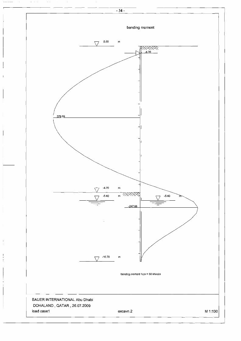
- 34
378.59
8.00
-4.70
-5.40
-10.70
bending moment
m
-4.39
m
m "
m
-247.68
bending moment 1cm =50 kNmlm
-5.40
BAUER INTERNATIONAL Abu Dhabi
DOHALAND, QATAR, 26.07.2009
load case1 excavn.2 M 1:100

I
,--------------------------------------------
-14.65
-5.40 m
136.76
- 3S
shear force
8.00 m
~
-4.70 m
-5.40 m "
-10.70 m
shear force 1em =25 kNim
BAUER INTERNATIONAL Abu Dhabi
DOHALAND , QATAR, 26.07.2009
load case1 excavn.2 M 1:100 I

- 36
pass. earth press. pass. earth press.
(active earth pr.)
8.00 m
excavn.1 sand
~ =30.00, 6 = 20.00' ___9_~~_ m
y; = 19.00 kN/m
C = .00 kNlm
sims
~ =40.00, 6 = 26.70'
y; = 22.00 kNlm
C = 40.00 kNlm
excavn.2
-4.70 m shal
= 40.00, 6 = 26.70'~ -5.40 m y,n = 22.00, Y; '= 13.00 kNlm V
C = SO.OO kNlm
-10.70 m 5 .18
earth pressure 1cm = 20 kN/m
BAUER INTERNATIONAL Abu Dhabi
DOHALAND, QATAR, 26.07.2009
load case1 M 1:100
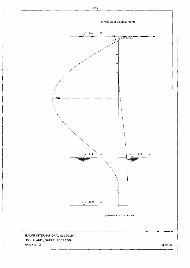
- 37
envelope of displacements
8.00 m -.78
7.22
V m -5.40 m-5.40
-10.70 m
displacemenl1 em =1.00 mm real
BAUER INTERNATIONAL Abu Dhabi
DOHALAND , QATAR, 26.07.2009
excavns. ,2 M 1:100 I
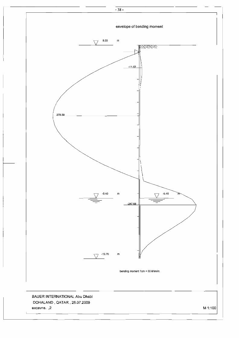
- 38
r
378.59
8.00
-5.40
-10.70
envelope of bending moment
m
-11.52
m
m
-247.68
bending moment 1cm = 50 kNmlm
-5.40
BAUER INTERNATIONAL Abu Dhabi
DOHALAND , QATAR, 26.07.2009
excavns. ,2 M 1:100
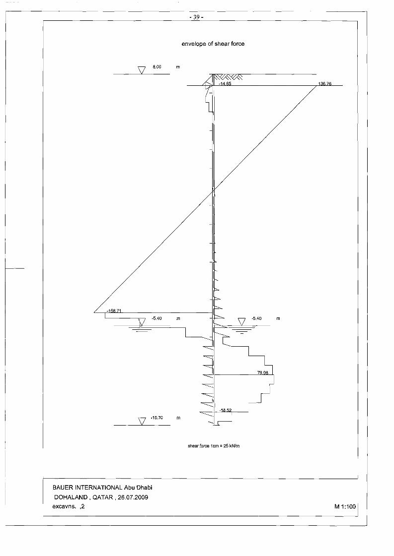
- 39
envelope of shear force
8.00 m
-14.65 13 .76
-5.40 m m
-10.70 m
shear force 1em =25 kN/m
BAUER INTERNATIONAL Abu Dhabi
DOHALAND, QATAR, 26.07.2009
excavns. ,2 M 1:100 I
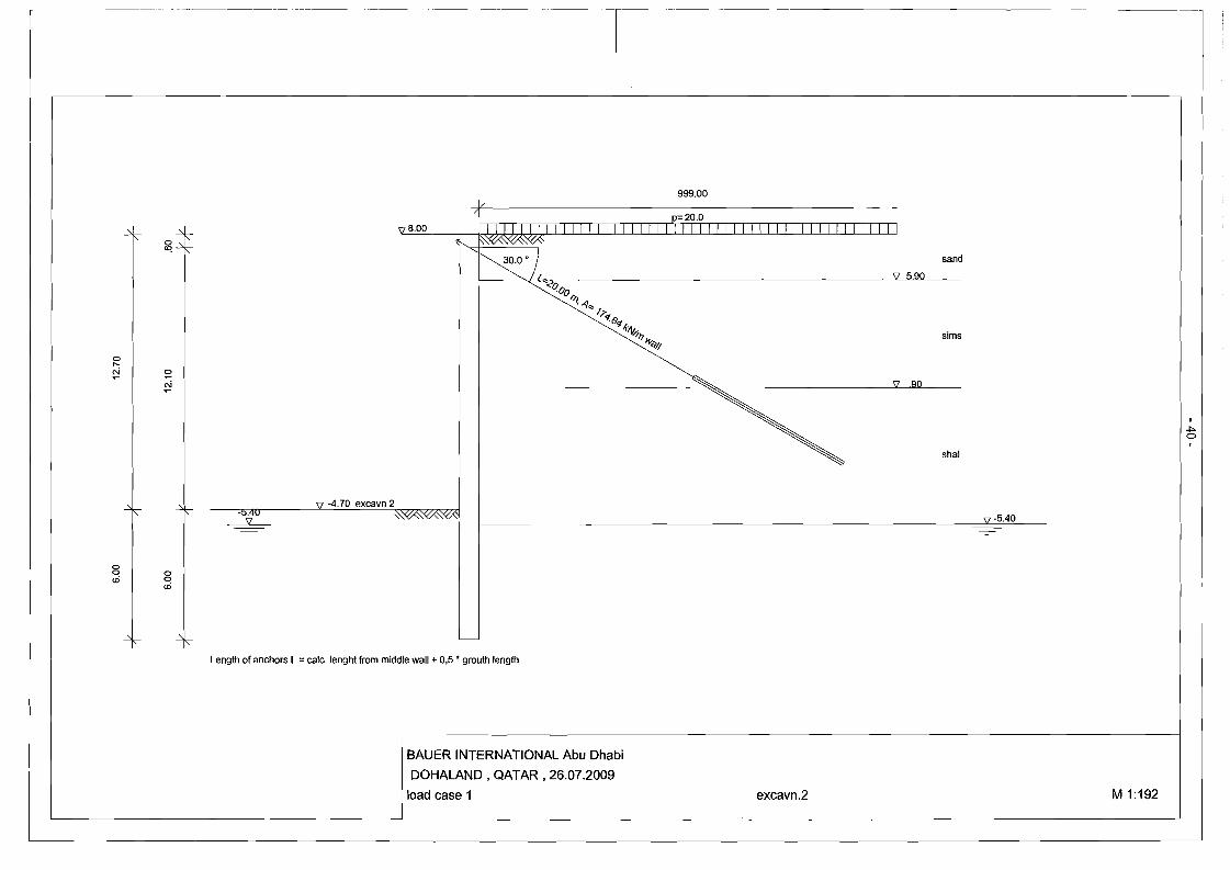
o ~
sand
\l 5.90("<0
o .... oN N
-4.70 excavn 2
~ "
:5 o ocO cO
·00 ~.<j'"
?'1 .6''1.(-I\t"
°"'6'4'
\l .90
sims
shal
\l -5.40
Length of anchors L =calc. lenght from middle wall + 0,5 • grouth length
BAUER INTERNATIONAL Abu Dhabi
DOHALAND, QATAR. 26.07.2009
load case 1 excavn.2 M 1:192
01>o
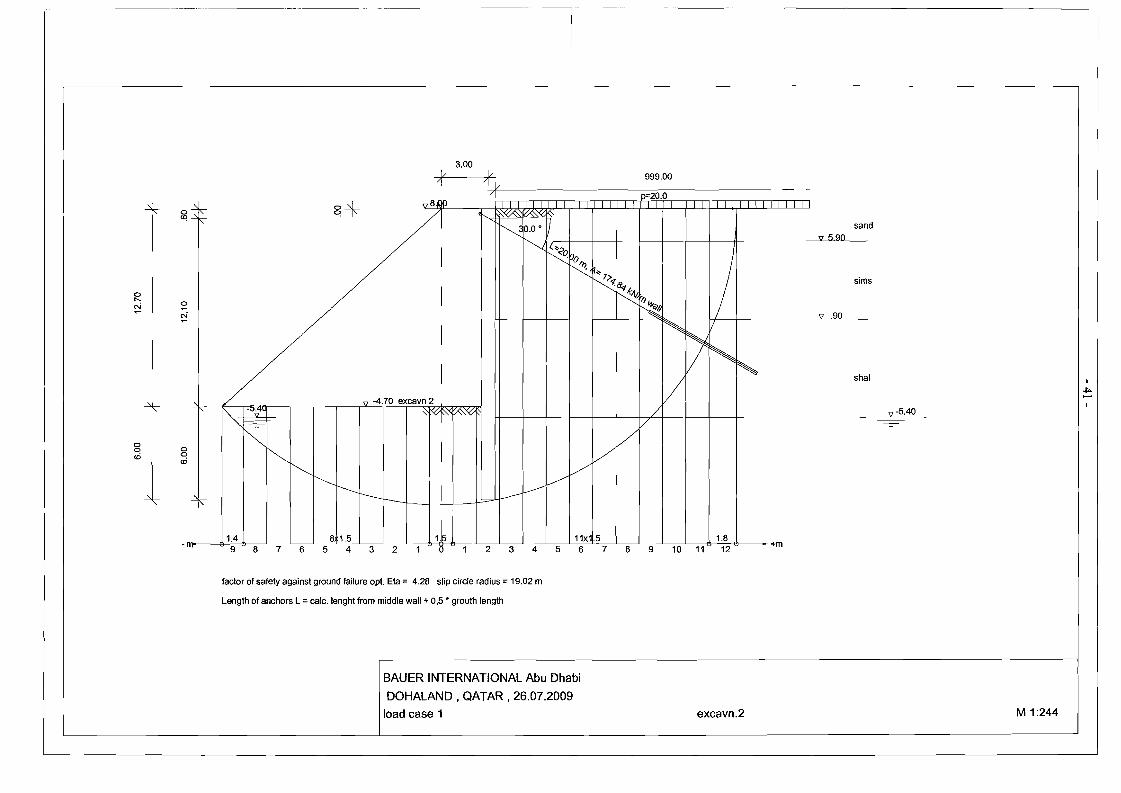
-+ 3.00
~/ 999.00
"
~4-~~
a .... a
'" ~
-4.70+
a a cD I I I~ I I
I~ I I I I I
1 A I '~l
0 ( 0 :i 4 3 2 1 1"
8.OP P 20.0
excavn 2
~l'
I I
I 'I
I
I~-
shal
sims
'V -5.40
" 5.90
+m
sand
('\"(;1 v0, k1 _____--'L'II----"'90"-----_
H--~--+--I---+--t----t
/
1
I
I
I
I
factor of safety against ground failure opt. Eta = 4.28 slip circle radius = 19.02 m
Length of anchors L =calc. lenght from middle wall + 0,5 • grouth length
BAUER INTERNATIONAL Abu Dhabi
DOHALAND , QATAR, 26.07.2009
load case 1 excavn.2 M 1:244
~ ,....
3.2
- 42- .•••.<.•••~ItII LONGITUDINAL REINFORCEMENT
Mmax 378.59 KN.m/m Refer to page: 25
Pile Diameter 900mm
Spacing of piles @ = 0.95 m
Load factor 11 =1.4
Steel grade fy = 460 N/mm2
Concrete grade feu = 40 N/mm2
~ M = 378.59 x 0.95 m x 1.4 = 503.5 KN.m/pile
M = 503.5 X 106 = 0.7 ""ii'3 9003
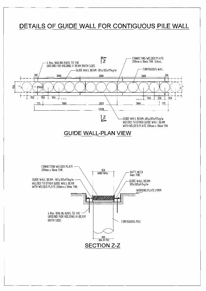
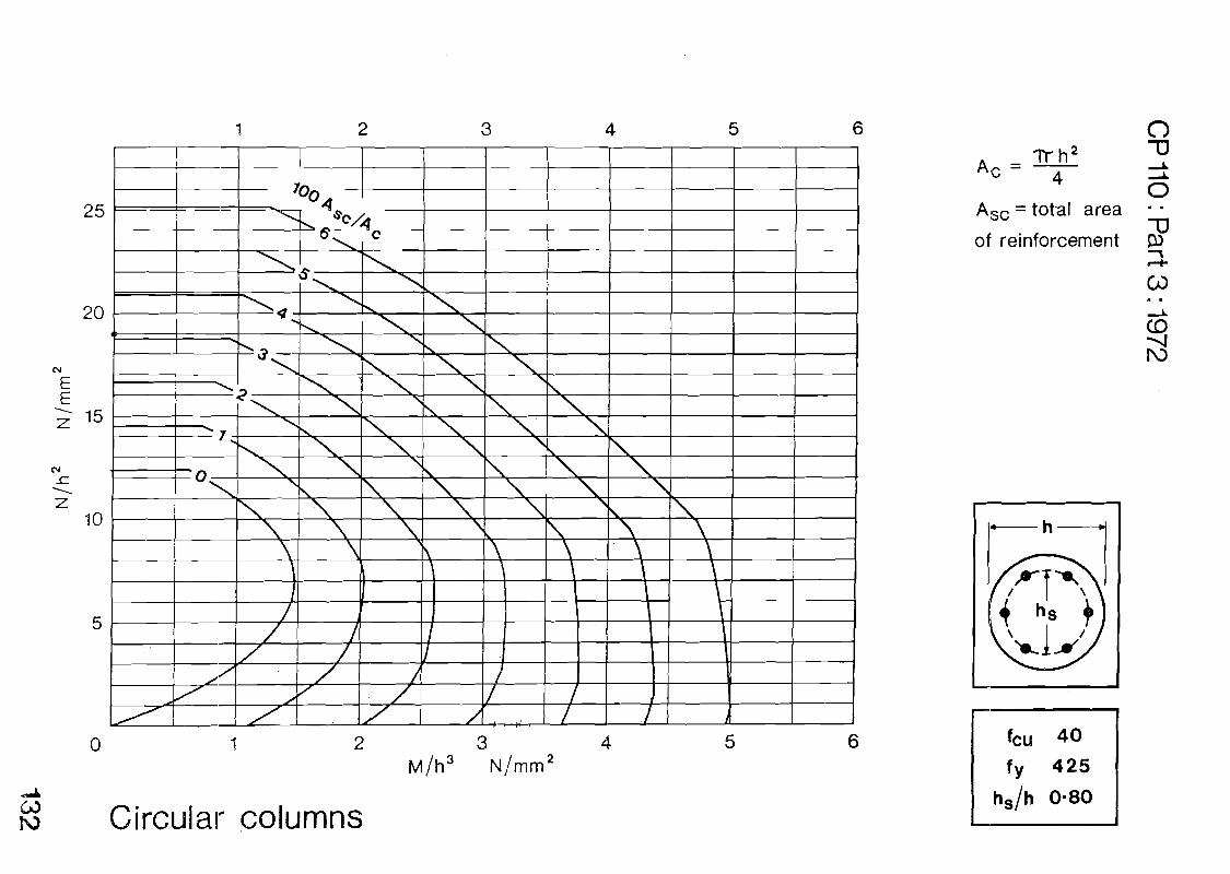
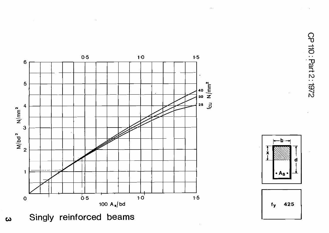
According to CP 110 : Part 3: 1972
Design Chart 132 (see Appendix)
M 100 As = 0.7 ~ = 0.7
h3 Ac
= 902 X 7t x.1. = 6362 cm2
4
As req. = 0.7 x 6362 = 44.5 cm2
100
Proposed: 10 $ 25 mm
As = 49.1 cm2 > As = 44.5 cm2
24/08/09 Issue 1 Rev.O MS/RW/SP/080/QT-22
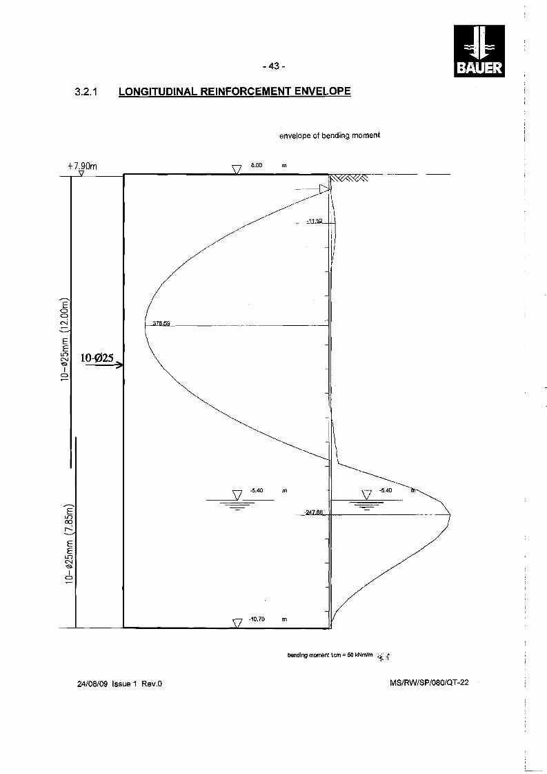
- 43
3.2.1 LONGITUDINAL REINFORCEMENT ENVELOPE
envelope of bending moment
8.00 m+7.90m
----dt- \
___ ,J
..--... E
<:) <:)
N
E E ~ SI
<:)
10-025
1---""-'LilclL.-
\ -
..--...
V -5.40 m -5.40
E \..C") CXJ r-
E E
\..C") N SI
<:)
- 4
-10.70 m
bending momenl1cm = 50 kNmlm {{::-i
24/08/09 Issue 1 Rev.O MS/RW/SP/080/QT-22
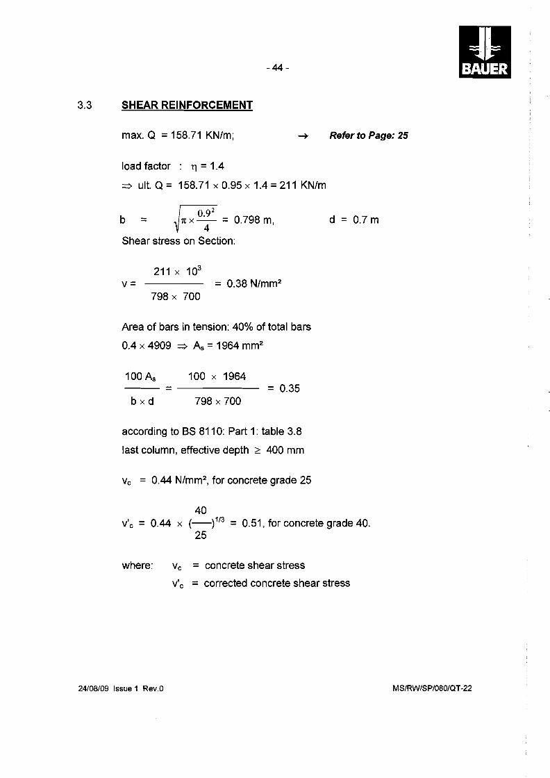
3.3
- 44 II SHEAR REINFORCEMENT
max. Q =158.71 KN/m; Refer to Page: 25
load factor : 11 =1.4
=> ult. Q = 158.71 x 0.95 x 1.4 = 211 KN/m
[(;92b = ~1tX~ = 0.798 m, d = 0.7 m
Shear stress on Section:
211 x 103
v= = 0.38 N/mm 2
798 x 700
Area of bars in tension: 40% of total bars
0.4 x 4909 => As = 1964 mm2
100 As 100 x 1964 --- = = 0.35
b x d 798 x 700
according to BS 8110: Part 1: table 3.8
last column, effective depth :?: 400 mm
Vc = 0.44 N/mm 2, for concrete grade 25
40 v'c = 0.44 x (_)1/3 = 0.51, for concrete grade 40.
25
where: Vc = concrete shear stress
v'c = corrected concrete shear stress
24/08/09 Issue 1 Rev.O MS/RW/SP/080/QT-22
--------------------------------------------
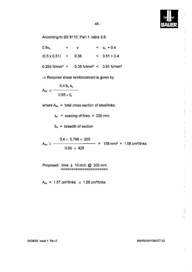
- 45
According to BS 8110: Part 1: table 3.8:
0.5vc < v < Vc + 0.4
(0.5 x 0.51) < 0.38 < 0.51 + 0.4
0.255 N/mm2 < 0.38 N/mm2 < 0.91 N/mm2
=> Required shear reinforcement is given by:
0.4 bv Sv
Asv ~ ----
0.95 x fy
where Asv = total cross section of steel/links
Sv = spacing of links = 200 mm
bv = breadth of section
0.4 x 0.798 x 200 Asv ~ --------- = 158 mm2 = 1.58 cm2/links
0.95 x 425
Proposed: links <I> 10 mm, @ 200 mm
Asv = 1.57 cm2/links _ 1.58 cm2/links
24/08/09 Issue 1 Rev.O MS/RW/SP/080/QT-22
----------------
- 46
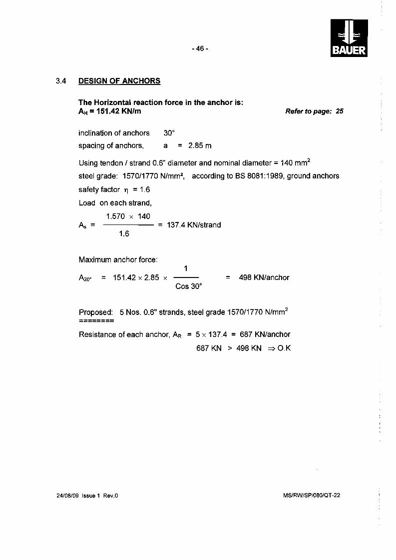
3.4 DESIGN OF ANCHORS
The Horizontal reaction force in the anchor is: AH = 151.42 KN/m Refer to page: 25
inclination of anchors 30°
spacing of anchors, a = 2.85 m
Using tendon 1strand 0.6" diameter and nominal diameter =140 mm2
steel grade: 1570/1770 N/mm2, according to BS 8081: 1989, ground anchors
safety factor 11 =1.6
Load on each strand,
1.570 x 140 ----- = 137.4 KN/strand
1.6
Maximum anchor force: 1
A20· = 151.42 x 2.85 x = 498 KN/anchor Cos 30°
Proposed: 5 Nos. 0.6" strands, steel grade 1570/1770 N/mm2
Resistance of each anchor, AR = 5 x 137.4 = 687 KN/anchor
687 KN > 498 KN => O.K
24/08/09 Issue 1 Rev.O MS/RW/SP/080/QT-22
- 47
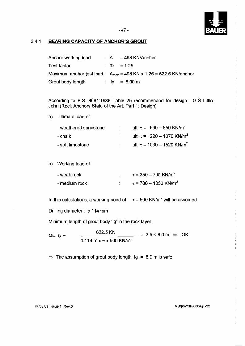
3.4.1 BEARING CAPACITY OF ANCHOR'S GROUT
Anchor working load A =498 KN/Anchor
Test factor Tf =1.25
Maximum anchor test load: Amax =498 KN x 1.25 =622.5 KN/anchor
Grout body length 'Ig' = 8.00 m
According to B.S. 8081:1989 Table 25 recommended for design; G.S Little John (Rock Anchors State of the Art, Part 1: Design)
a) Ultimate load of
- weathered sandstone ult 't = 690 - 850 KN/m2
- chalk ult 't = 220 - 1070 KN/m2
- soft limestone ult 't =1030 - 1520 KN/m2
a) Working load of
- weak rock 't =350 - 700 KN/m2
- medium rock 't =700 - 1050 KN/m2
In this calculations, a working bond of 't =500 KN/m2 will be assumed
Drilling diameter: <I> 114 mm
Minimum length of grout body 'Ig' in the rock layer:
622.5 KN Min. 4f = = 3.5 < 8.0 m :::::) OK
0.114 m x 1t X 500 KN/m2
:::::) The assumption of grout body length Ig = 8.0 m is safe
24/08/09 Issue 1 Rev.O MS/RW/SP/080/QT-22
- 48
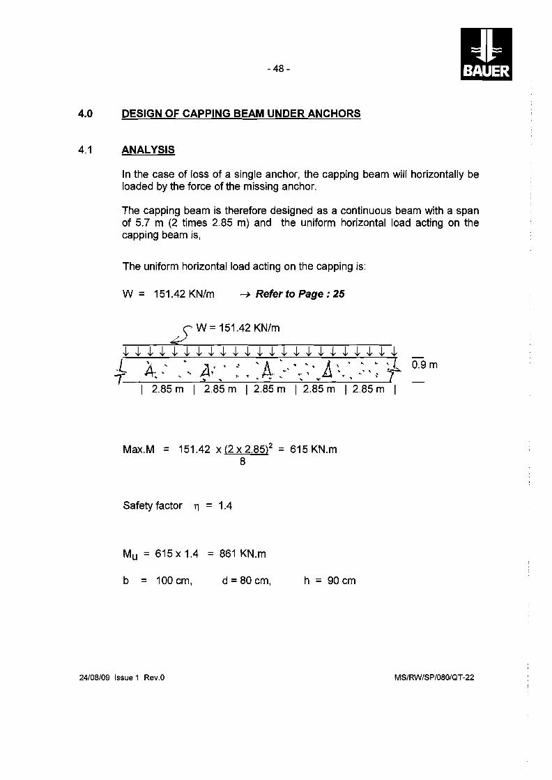
4.0 DESIGN OF CAPPING BEAM UNDER ANCHORS
4.1 ANALYSIS
In the case of loss of a single anchor, the capping beam will horizontally be loaded by the force of the missing anchor.
The capping beam is therefore designed as a continuous beam with a span of 5.7 m (2 times 2.85 m) and the uniform horizontal load acting on the capping beam is,
The uniform horizontal load acting on the capping is:
W = 151.42 KN/m ---+ Refer to Page : 25
\' W =151.42 KN/m k
~ ~ ~ ~ ~ ~ ~ ~ ~ ~ ~ ~ ~ ~ ~ ~ ~ ~ ~ ~ ~ ~ ~ '· , .. ;, r 'A-',," A, ' , .. ~ 1,.! 0.9 m
.. L A b..... .t-\' .... ~ '" .. '\ 7~f- '" '" f\'t"", ~,. :-' .... "'",'" ~_....... I 2.85 m I 2.85 m I 2.85 m I 2.85 m I 2.85 m I
Max.M = 151.42 x (2 x 2.85)2 = 615 KN.m 8
Safety factor 11 = 1.4
Mu = 615 x 1.4 = 861 KN.m
b = 100 cm, d =80 cm, h = 90 cm
24/08/09 Issue 1 Rev.O MS/RW/SP/080/QT-22

4.2
- 49
CAPPING BEAM - MAIN REINFORCEMENT
Mu = 861 KN.m
steel grade fy = 460 N/mm2
fc = 40 N/mm2
According to Design Chart 13, BS 8110, Part 3 (see Appendix).
M
bd2 =
861 x 103
100 x 802 = 1.34
100 As
bd = 0.38, say minimum 0.4
req. As = 0.4 x b
100
x d
= 0.4 x 100 x
100
80
req. As = 32 cm2 /m
We proposed: 5 <j> 32 mm, on each face
:::::> 40.2 cm2 > 32.0 cm2
24/08/09 Issue 1 Rev.O MS/RW/SP/080/QT-22
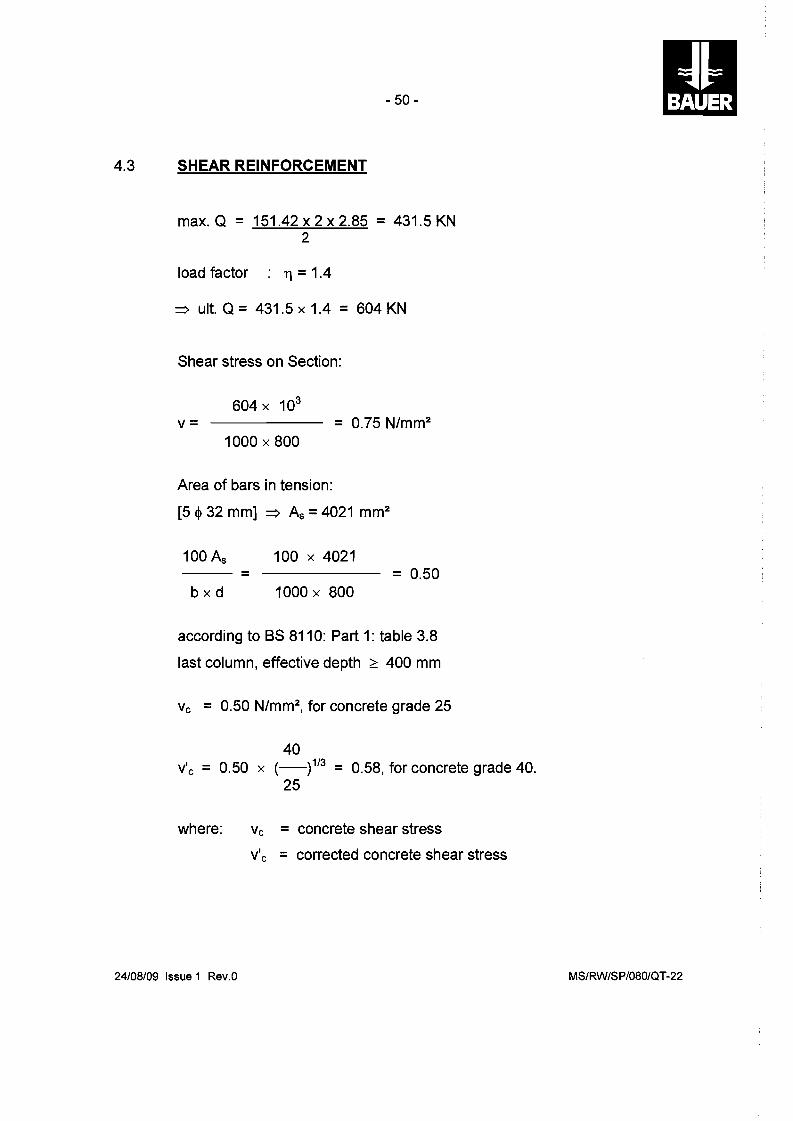
4.3
- 50
SHEAR REINFORCEMENT
max. Q = 151.42 x 2 x 2.85 = 431.5 KN 2
load factor 1']=1.4
=> ult. Q = 431.5 x 1.4 = 604 KN
Shear stress on Section:
604 x 103
v= = 0.75 N/mm2
1000 x 800
Area of bars in tension:
[5 $ 32 mm] => As = 4021 mm2
100 As 100 x 4021 -- = = 0.50
b x d 1000 x 800
according to BS 8110: Part 1: table 3.8
last column, effective depth :2:: 400 mm
Vc = 0.50 N/mm2, for concrete grade 25
40 v'c = 0.50 x (_)1/3 = 0.58, for concrete grade 40.
25
where: Vc = concrete shear stress
v'c = corrected concrete shear stress
24/08/09 Issue 1 Rev.O MS/RW/SP/080/QT-22

------------------------------------------
- 51 II According to BS 8110: Part 1: table 3.8:
0.5ve < v < rye + 0.4)
(0.5 X 0.58) < 0.75 < (0.58 + 0.4)
0.29 N/mm 2 < 0.75 N/mm2 < 0.98 N/mm2
~ Required shear reinforcement is given by:
0.4 bv Sv
0.95 x fy
where Asv = total cross section of steei/links
Sv = spacing of links = 150 mm
bv = breadth of section
0.4 x 1000 x 150 Asv ~ --------- = 137 mm2 = 1.37 cm2/links
0.95 x 460
Proposed: links ~ 10 mm, @ 150 mm
Asv =1.57 cm2/links ~ 1.37 cm2/1inks
24108/09 Issue 1 Rev.O MS/RW/SP/080/QT-22
- 52
APPENDIX
24/08/09 Issue 1 Rev.O MS/RW/SP/080/QT-22
1 2 3 456 o
N
E E
2
25; ~;~~cj f I I I I I I ...........
I Fl S~, f";;] I I l I I I I 20 I I ,............... <iff: f IS
"""'" " 15
~
\1 "\] 1\ 1\ I \ 1\ I \ \ I \
51 I
2 A = 11 h c 4
= total areaAsc .
of remforcement
•
feu 401 2 3 4 5 6 M/h 3 N/mm 2
ty 425 ........ hs/h 0·80 f\) 0J Circular .columns
'"U -J,. -J,.
o .. '"Um.., .-+
0J -J,.
~
-0
0·5 6
5
C'l 4
-z ~
3 C'l
1J ...c-~ 2
1
./
---
~
./~/
./~%/ ~ ~
~ ~/
....&~ V
~ ~
- - - / .,...:
7' V
/ V
:
o 0·5 100 A.I bd
w Singly reinforced beams
()
~ --10.
o . .1·0 1·5 '"1) m..., ...... I\)
C'l ,--10.E 'CO
40 E 30 -Z i\5 25 :J
oS
r-b---j
flRll y I''>.Y\,"\'>."'"'11 d
.As.ll
1·0 1·5 ty 425