c copyright 2011 the authors notice changes introduced as...
TRANSCRIPT

This is the author’s version of a work that was submitted/accepted for pub-lication in the following source:
Lin, Tian Ran, Tan, Andy, Howard, Ian, Pan, Jie, Crosby, Peter, & Mathew,Joseph (2011) Development of a diagnostic tool for condition monitoring ofrotating machinery. In ICOMS Asset Management Conference Proceed-ings, Asset Management Council Limited, Gold Coast Convention and Ex-hibition Centre, Queensland, pp. 1-9.
This file was downloaded from: http://eprints.qut.edu.au/41753/
c© Copyright 2011 The Authors
Notice: Changes introduced as a result of publishing processes such ascopy-editing and formatting may not be reflected in this document. For adefinitive version of this work, please refer to the published source:

1
Development of a diagnostic tool for condition monitoring of
rotating machinery
Tian Ran Lin a, b
, Andy C. C. Tan b, Ian Howard
c, Jie Pan
d, Peter Crosby
e and Joseph Mathew
a
a CRC for Infrastructure and Engineering Asset Management
b School of Engineering Systems, Queensland University of Technology
c Department of Mechanical Engineering, Curtin University of Technology d
School of Mechanical Engineering, the University of Western Australia e Australian Submarine Corporation
Summary: This paper presents an overview of the CRC for Infrastructure and Engineering Asset Management
(CIEAM)’s rotating machine health monitoring project and the status of the research progress. The project focuses on
the development of a comprehensive diagnostic tool for condition monitoring and systematic analysis of rotating
machinery. Particularly attention focuses on the machine health monitoring of diesel engines, compressors and pumps
by using acoustic emission and vibration-based monitoring techniques. The paper also provides a brief summary of the
work done by the three main research collaborating partners in the project, namely, Queensland University of
Technology (QUT), Curtin University of Technology (CUT) and the University of Western Australia (UWA).
Preliminary test and analysis results from this work are also reported in the paper.
Keywords: Condition monitoring, Acoustic Emission, Vibration, Machine diagnostics
1 INTRODUCTION
Rotating machinery such as diesel engines, pumps, and compressors is one of the most critical classes of equipment in industry
today. Unpredicted failures in this category of machine often results in dire consequences. For instance, a sudden breakdown of
the diesel engine in a submarine propulsion system or a sudden failure of a compressor providing coolant to a nuclear reactor
could cause both financial and human losses. To minimize and prevent unpredicted machine breakdowns, it is imperative to
develop a comprehensive tool to continually monitor machine operating conditions and accurately diagnose/identify faulty
machine components when fault develops. Nowadays, Condition Monitoring (CM) techniques are being gradually adopted in
the industry to avoid unpredicted failures. CM not only helps to improve the reliability of a machine but also improves
maintenance and asset management decision making.
In previous CIEAM projects [1, 2], Acoustic Emission (AE) technique was successfully applied in the monitoring of a low
speed paste mixer gearbox at an Aluminium smelter [1] using a remote data acquisition and analysis system. The technique
was also employed to monitor the condition of the marine diesel engine. The AE technique produced superior signal to noise
ratios when compared with the more traditional vibration monitoring method in terms of detecting incipient faults, particularly,
in a noisy environment with strong signal interference from the background noise [2]. An online data acquisition and analysis
software – COMOLOS (which stands for Condition Monitoring of Low Speed machinery) was also developed in the previous
work. This software has several modules including online remote control of data acquisition setup and data transfer, online
real-time analysis, offline analysis and trending. The software, coupled with a data acquisition system and sensors, was
installed and tested successfully in the remote condition monitoring of the paste mixer. The data was acquired and analysed
remotely through the internet [2] thus enabling continuous monitoring with the potential to minimise production outages.
The current CIEAM project [3] utilises and further expands the knowledge and techniques developed in the previous projects.
It aims to integrate and develop a comprehensive diagnostic tool for condition monitoring and asset health management of
rotation machinery, particularly for condition monitoring of diesel engines, pumps and compressors. Researchers from three
participating institutions – QUT, CUT and UWA are working collaboratively on the project with each team focusing on
different aspects and applications of the project. The outputs of this project, which includes new signal processing techniques,
together with the revised and updated version of COMOLOS software will be integrated into a Harmonised Asset Management
Integrated Service Hub (HAMISH) by the end of this project.

2
2 LITERATURE REVIEW
CM is a technique used to monitor the operating state and health of a machine, and to detect potential machine failures before
they materialize and become a functional failure. The process consists of periodical or continuous data collection, analysis,
interpretation and diagnosis. CM forms an integral part of Condition-Based Maintenance (CBM) which schedules machine
maintenance activities for the monitored asset. CM optimises equipment readiness while reducing maintenance and operating
costs. Typical CM techniques include vibration analysis [4-7], oil analysis [8, 9], wear particle analysis [6], in-cylinder
pressure analysis [10, 11] and instantaneous crank angular speed (IAS) [12, 13].
The in-cylinder pressure method provides a direct indication of engine performance and operating conditions. Nevertheless, in-
cylinder pressure analysis is limited by the intrusive nature of the technique. Its application is also hampered by the concerns
over reliability, and high instrumentation costs. Oil and wear particle analysis provides an indication of the wear of mechanical
components inside the engine. The technique is applied mostly to wear-related problems of rotating machines. The IAS
technique has attracted the attention of many researchers in recent years. However, the performance of the technique varies
between applications and it is only effective when the number of cylinders under test is less than 10 [14]. Multi-cylinder
engines involve higher inertia, overlapping combustion events and torsional vibration of the flexible crankshaft, which
complicates the diagnostics [15]. The vibration method is one of the proven classical techniques and has been widely employed
for condition monitoring of machine health for several decades. In this project, the technique is used for the condition
monitoring of centrifugal pumps by researchers at CUT and UWA.
Recently, Kim et al [2] has shown that AE has a better signal to noise ratio than vibration in a high background noise
environment. Kim et al [15] further showed that AE RMS signal is more sensitive and responsive to the mechanical events in
an engine than vibration acceleration RMS signal. Additionally, the AE technique has been successfully employed for bearing
fault detection in low speed rotating machines [16-18] and condition monitoring of diesel engines [19-21]. The technique is
utilized in this project for condition monitoring of diesel engines and compressors by the researchers at QUT.
3 AN OVERVIEW OF THE COMOLOS DATA ACQUISITION AND ANALYSIS SOFTWARE
A brief overview of the COMOLOS condition monitoring software developed in the previous CIEAM project [2] is presented
in this section. The software developed in the Labview environment, directly controls the data acquisition system and sensors
coupled to it. The software has several modules including remote data acquisition and transfer control, real time diagnostic
analysis, offline diagnostic analysis, feature extraction and trend analysis. A few screen shots of the software and its features
are shown in Fig. 1. In this project, COMOLOS will be revised and expanded to monitor the condition of rotating machinery in
general.
(a) Main Menu (b) Bearing and gear data input window

3
(c) Data acquisition setup window (d) Real time spectrum analysis window
(e) Offline analysis window (f) Offline feature trending window
Fig. 1 Screen shots of the COMOLOS condition monitoring and diagnosis software tool
4 FAILURE MODE ANALYSIS
The researchers at QUT and CUT had undertaken failure mode analysis of diesel engines, pumps and compressors in the early
part of this project aiming to have a better understanding of the principal failure modes of these rotating machines, and to
establish a practical condition monitoring program.
Diesel Engines The failure modes of a diesel engine can either be grouped by the engine sub-systems such as the fuel injection system, the
valve system, cylinders/pistons and the cooling system or they can be classified according to fault symptoms. A summary of
the common faults of diesel engines and their related symptoms is presented in Table 1. The patterns and symptoms are to be
used for fault detection and diagnosis of diesel engines. Several common failure modes of diesel engines are chosen for fault
simulation in the experimental investigation.
Screw Compressors The literature survey shows that research on these classes of equipment is limited. So far, there is no specific ISO vibration
standard covering screw compressors. The most common reason for compressor failure or component damage of rotary screw
compressors is due to process instability or lubrication problems. Screw compressors are designed to deliver a constant volume
and pressure of air and gas, which is susceptible to changes in either inlet or discharge conditions. A slight variation in
pressure, temperature, or volume can result in instantaneous failure. Bearing failure is the most common failure mode of a
rotary screw compressor. Thrust bearings are more susceptible to process instability or abnormal compressor dynamics
although both thrust (angular contact) and journal (cylindrical) bearings are affected by process instability. Lubrication
problems are also a common cause of bearing failure in an oil-flooded type screw compressor. Crack or damage of rotor
screws is another common failure mode of screw compressors. Thrust bearings need to be monitored closely where signs of
degradation or excessive axial clearance should be addressed immediately. The main tonal components of screw compressor

4
noise including bearing frequencies, lope pass frequency, rotor mesh frequency and their higher harmonics could be utilized as
indicators for monitoring screw compressors.
Table 1 Common diesel engine failure modes and the related fault symptoms
Failure modes Symptoms
Incorrect valve timing
Incorrect valve clearance
Faulty fuel injector /calibration
Faulty injection pump
Air entering fuel system
Fuel line restriction
Compression loss
Misfire
Faulty injectors
Faulty fuel pump
Incorrect valve or fuel pump timing
Turbocharger fault
Contaminated fuel
Restricted fuel supply
Restricted exhaust system
Low or insufficient
power
Cooling system fault/coolant leakage
Blocked radiator
Incorrect injection pump timing
Faulty fuel injectors
Mechanical fault with engine, gasket fault
Cracked cylinder head or cylinder block
Overheating
Insecure engine components/mechanical failure
Incorrect pump/valve/engine timing
Incorrect fuel injector calibration/fault
Pre-combustion chamber loose
Excessive mechanical
noise
Incorrect injection pump timing
Injection pump over fuelling
Faulty/dirty fuel injectors
Restricted air intake or air filter blocked
Excessive black exhaust
smoke
Incorrect valve timing
Incorrect injection pump timing
Low injector opening pressure
Low cylinder compression pressure
Low turbocharger boost pressure
Restricted air intake
Water entering combustion chambers
Excessive white / grey
smoke
Starter motor or related wiring fault
Air entering fuel system
Relay/wiring faulty
Incorrect valve timing
Incorrect injection pump timing
Faulty fuel injectors
Fuel supply line blocked or primer pump inoperative
Fuel injector pipes incorrectly fitted
High pressure fuel injection pump fault
High pressure system loss of pressure
Failure of electronic control system sensors/wiring
Failure of diesel control unit
Air intake system blocked/restricted
Exhaust system blocked or restricted
Engine condition causing low compression pressure
Engine will not start

5
Centrifugal Pumps
In parallel to the work done by the researchers at QUT on the failure mode analysis of diesel engines and screw compressors,
the research team at CUT undertook a failure mode analysis of centrifugal pumps in which 14 major mechanical problems of
centrifugal pumps were identified [22]:
• Cavitation
• Impeller problems
• Mechanical failure (bearings, seals, etc.)
• Erosion
• Corrosion
• Nodular growth
• Excessive vibrations
• Pressure pulsations
• Radial thrust
• Axial thrust
• Excessive noise
• Fatigue
• Excessive power consumption
• Suction and discharge recirculation
In particular, the failure mode analysis of water utility pumps [23] indicates that the most common reason for failure is
blockages. Blocked flow reduces the efficiency of pumps and may lead to other faults such as cavitation and wear. Some
faults, such as leakage, also affect the flow behaviour. Hence, monitoring flow intake and discharge conditions may reveal
information about a pump’s performance. Direct flow measurement requires sensors to be inserted directly into the piping or
pump casing, which may not be practical in many applications. An alternative method is to measure flow behaviour indirectly
such as vibration measurements. Changes in flow produce vibration, and thus it is possible to monitor flow conditions by
monitoring the vibration signal at various locations on a pump. The research team at UWA is currently investigating detection
of reduced pump working efficiency and changes in flow intake and discharge conditions by using the pump’s vibration
signals [24]. Optimum sensor locations for pump condition monitoring are also investigated.
For an accurate detection and diagnoses of a faulty component in a rotating machine, it is imperative to establish a reliable and
robust algorithm to characterize various faults of a machine at different operating conditions. Simulation of these faults in a
controlled manner is important to determine the feature that best aids the signal processing and feature extraction of each fault.
To this end, an engine test rig was purchased for fault simulation and characterization of diesel engines at QUT. An existing
centrifugal pump test rig at UWA is also utilized in the project to simulate and identify the effects of certain failure behaviour
on vibration signatures of a centrifugal pump [24]. The UWA team focuses on the study of the flow/impeller/pump casing
interaction, as this interaction strongly dominates the pump’s vibration signature. This understanding may provide a tool for
condition monitoring of typical causes of pump failures such as restricted flows due to blockage in flow path and change in
flow conditions.
5 DESCRIPTION OF QUT’S DIESEL ENGINE TEST RIG AND PRELIMINARY ANALYSIS RESULTS
Simulation of typical faults in a diesel engine is vital for fault detection and diagnosis since actual faults normally do not
happen in a short period of time. Common faults in diesel engines including their respective symptoms were discussed and
summarized in the previous section. Several faults including injector faults, valve faults, cylinder and piston related faults are
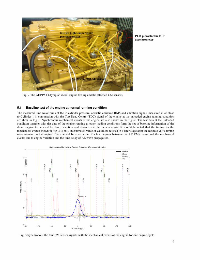
to be implemented in the simulations. A GEP18-4 Olympian diesel engine generator set was purchased for this purpose, which
is shown in Fig. 2. The diesel engine generates about 15kW of output power and is connected to a three-phase 15kW industrial
fan heater. The heater has three heat settings, which can be adjusted during the simulation test for different engine loadings.
Four resonance type (PAC Micro-30D) acoustic emission sensors are attached onto the engine block close to each of the four
cylinders by aluminium sensor holders as shown in Fig. 2. A Kistler high temperature pressure sensor is tightly fitted into
Cylinder 1 through a pre-drilled hole. A PCB industry ICP accelerometer is stud mounted on the engine block close to
Cylinder 1 as indicated in Fig. 2. An encoder and a TDC recorder are directly fitted onto the crankshaft to measure the
instantaneous angular velocity of the shaft and the top dead centre of the cylinders.
6
Fig. 2 The GEP19-4 Olympian diesel engine test rig and the attached CM sensors
5.1 Baseline test of the engine at normal running condition
The measured time waveforms of the in-cylinder pressure, acoustic emission RMS and vibration signals measured at or close
to Cylinder 1 in conjunction with the Top Dead Centre (TDC) signal of the engine at the unloaded engine running condition
are show in Fig. 3. Synchronous mechanical events of the engine are also shown in the figure. The test data at the unloaded
condition together with the data of the engine running at other loading conditions form the set of baseline information of the
diesel engine to be used for fault detection and diagnosis in the later analysis. It should be noted that the timing for the
mechanical events shown in Fig. 3 is only an estimated value, it would be revised in a later stage after an accurate valve timing
measurement on the engine. There would be a variation of a few degrees between the AE RMS peaks and the mechanical
events due to engine variation and the time delay of AE wave propagation.
Fig. 3 Synchronous the four CM sensor signals with the mechanical events of the engine for one engine cycle
Kistler high temperature
pressure sensor PCB piezoelectric ICP
accelerometer
PAC Micro-30D AE sensors
-360 -270 -180 -90 0 90 180 270 360-0.5
0
0.5
1
1.5
2
2.5
3
3.5
4
Pressure
Crank Angle
Am
plitu
de
(V
)
Synchronous Mechaincal Events, Pressure, AErms and Vibration
CO
MB
1
EV
O1
IVO
1
EV
C1
IVC
1
CO
MB
2
EV
O2
IVO
2
EV
C2
IVC
2
CO
MB
3
EV
O3
IVO
3
EV
C3
IVC
3
CO
MB
4
EV
O4
IVO
4
EV
C4
IVC
4
Pressure
AE rms
Vibration
TDC
7
In Fig. 3, EVC denotes exhaust valve closing, EVO stands for exhaust valve opening, IVC represents inlet valve closing, IVO
represents inlet valve opening and COMB denotes engine combustion.
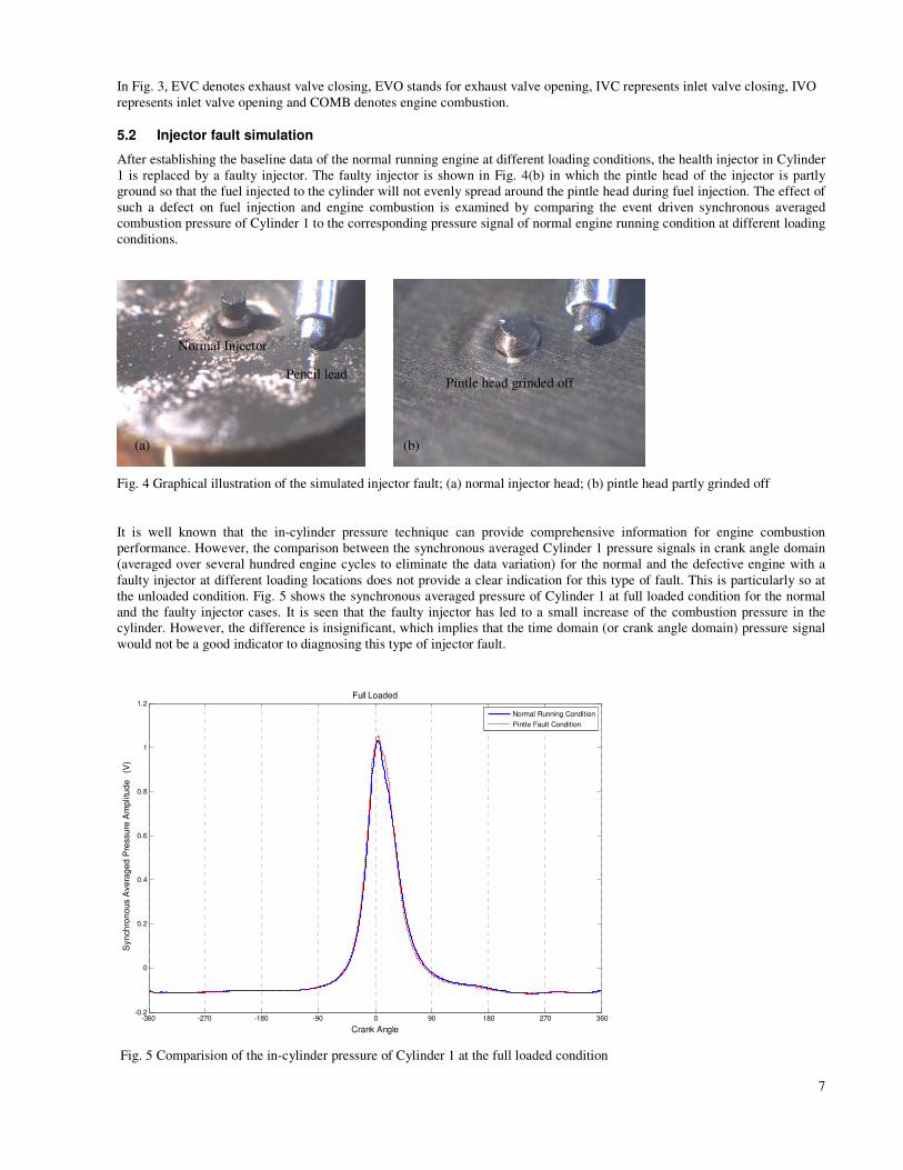
5.2 Injector fault simulation
After establishing the baseline data of the normal running engine at different loading conditions, the health injector in Cylinder
1 is replaced by a faulty injector. The faulty injector is shown in Fig. 4(b) in which the pintle head of the injector is partly
ground so that the fuel injected to the cylinder will not evenly spread around the pintle head during fuel injection. The effect of
such a defect on fuel injection and engine combustion is examined by comparing the event driven synchronous averaged
combustion pressure of Cylinder 1 to the corresponding pressure signal of normal engine running condition at different loading
conditions.
Fig. 4 Graphical illustration of the simulated injector fault; (a) normal injector head; (b) pintle head partly grinded off
It is well known that the in-cylinder pressure technique can provide comprehensive information for engine combustion
performance. However, the comparison between the synchronous averaged Cylinder 1 pressure signals in crank angle domain
(averaged over several hundred engine cycles to eliminate the data variation) for the normal and the defective engine with a
faulty injector at different loading locations does not provide a clear indication for this type of fault. This is particularly so at
the unloaded condition. Fig. 5 shows the synchronous averaged pressure of Cylinder 1 at full loaded condition for the normal
and the faulty injector cases. It is seen that the faulty injector has led to a small increase of the combustion pressure in the
cylinder. However, the difference is insignificant, which implies that the time domain (or crank angle domain) pressure signal
would not be a good indicator to diagnosing this type of injector fault.
-360 -270 -180 -90 0 90 180 270 360-0.2
0
0.2
0.4
0.6
0.8
1
1.2
Crank Angle
Syn
ch
ron
ou
s A
ve
rag
ed
Pre
ssu
re A
mp
litu
de
(
V)
Full Loaded
Normal Running Condition
Pintle Fault Condition
Fig. 5 Comparision of the in-cylinder pressure of Cylinder 1 at the full loaded condition
(a) (b)
Normal Injector
Pintle head grinded off Pencil lead

8
Similarly, we compared the synchronous averaged AE RMS signals measured at Cylinder 1 for the normal and the faulty
injector cases and the results are shown in Fig. 6 for the full load condition. It is found that the AE RMS signal can provide a
clear indication of the changing engine combustion condition due to the faulty injector of the cylinder at the fully loaded
condition (see the amplitude change of the peaks enclosed by the two ellipses, where both peaks are associated with the
mechanical events in Cylinder 1). Although the synchronous averaged time domain (or crank angle domain) AE RMS signals
at other loading conditions (which are not shown in this paper) do not provide an explicit indication of this injector fault, the
main frequency components of their corresponding frequency spectra show a clear and consistent pattern as those shown in the
spectrum of the fully loaded condition for this fault. The analysis in the frequency domain is not presented and discussed here
to limit the length of this paper. It is also noted that this preliminary result partly confirms that acoustic emission could be
employed to detect incipient injector faults as shown in Figs. 5 and 6.
-360 -270 -180 -90 0 90 180 270 360
0
1
2
3
4
Crank Angle
AE
rms A
mplitu
de (V
)
Synchronous Averaged AErms at the full loaded condition
CO
MB
1
EV
O1
IVO
1
EV
C1
IVC
1
CO
MB
2
EV
O2
IVO
2
EV
C2
IVC
2
CO
MB
3
EV
O3
IVO
3
EV
C3
IVC
3
CO
MB
4
EV
O4
IVO
4
EV
C4
IVC
4
Normal Condition
Injector Pintle fault
TDC
Cylinder 1
Cylinder 2
Cylinder 3
Cylinder 4
Fig. 6 Synchronous averaged AE RMS signals at full loaded condition
6 CONCLUSIONS
In this paper, we presented a brief summary of the techniques and software developed in CIEAM projects for condition
monitoring of low speed machinery. Cases of successful application of the condition monitoring techniques developed in these
projects were presented and discussed. The paper also provided a brief introduction of the condition monitoring and diagnosis
software – COMOLOS developed in CIEAM and its capability for remote data acquisition, condition monitoring and signal
analysis. A brief summary of the failure modes of three most commonly used rotating machines, diesel engines, pumps and
screw compressors were reported in the paper. The main condition monitoring techniques were reviewed and the techniques
most suitable for this project were identified.
An experimental test rig was purchased and installed for simulating faults in a diesel engine at QUT. An existing centrifugal
pump test rig at UWA was used to simulate and identify the effects of certain failure behaviour on the vibration signatures of a
centrifugal pump [24]. Preliminary analysis of the test data on the diesel engine was also presented and discussed in the paper.
It was found that AE performs better than the in-cylinder pressure method in detecting simulated injector faults in the crank
angle domain. The result also partly confirms that AE has the potential to detect incipient injector faults in diesel engines.
7 ACKNOWLEDGEMENTS
This paper was developed within the CRC for Infrastructure and Engineering Asset Management, established and supported
under the Australian Government's Cooperative Research Centres Programme. The authors gratefully acknowledge the
financial support provided by the CRC. The design and commissioning of the diesel engine test rig by Dr Eric Kim and Mr
David Lowe of QUT is gratefully acknowledged.

9
8 REFERENCES
1. E. Kim, A. C. C. Tan, V. Kosse, I. Howard and T. Tan, Condition monitoring of low speed machinery. CIEAM Final
Project Report, ID202, 2010.
2. E. Kim, A. C. C. Tan, V. Kosse, I. Howard and T. Tan, Utilisation of condition monitoring/diagnostics software for low
speed machinery. CIEAM Final Project Report, ID208 2010.
3. A. C. C.Tan, I. Howard, J. Pan, T. R. Lin, et al., Rotating Machinery Health Manager (RMHM). CIEAM II Project
ID3102, 2011.
4. J. Mathew, Machine condition monitoring using vibration analysis. Journal of the Australia Acoustical Society 1987. 15:
p. 7-13.
5. Y. Gao and R. Randall, Reconstruction of diesel engine cylinder pressure using a time domain smoothing technique.
Mechanical System and Signal Processing, 1999. 13 (5): p. 709–722
6. S. Ebersbach, Z. Peng, and N. J. Kessissoglou, The investigation of the condition and faults of a spur gearbox using
vibration and wear debris analysis techniques. Wear, 2006. 260(1-2): p. 16-24.
7. A. P. Carlucci, F. F. Chiara and D. Laforgia, Analysis of the relation between injection parameter variation and block
vibration of an internal combustion diesel engine. Journal of Sound and Vibration, 2006. 295(1-2): p. 141-164.
8. E. N. Gary, Oil analysis cost-effective machine condition monitoring technique. Industrial Lubrication and Tribology,
1999. 51(3): p. 119.
9. W. Wang, An integrated on-line oil analysis method for condition monitoring". Measurement Science and Technology,
2003. 14(11): p. 1973-1977.
10. J. B. Heywood, Internal Combustion Engine Fundamentals. 1988.
11. S. J. Citron, J. E. O’Higgins and L. Y. Chen, Cylinder by Cylinder Engine Pressure and Pressure Torque Waveform
Determination Utilizing Speed Fluctuations. SAE 8900486, 1989.
12. R. Johnsson, Cylinder pressure reconstruction based on complex radial basis function networks from vibration and speed
signals. Mechanical Systems and Signal Processing, 2006. 20(8): p. 1923-1940.
13. J. Yang, L. Pu, Z. Wang, Y. Zhou and X. Yan, Fault detection in a diesel engine by analysing the instantaneous angular
speed. Mechanical Systems and Signal Processing, 2001. 15(3): p. 549–564
14. Y. Ren, T. Hu, P. Yang and X. Liu, Approach to Diesel Engine Fault Diagnosis Based on Crankshaft Angular
Acceleration Measurement and its Realization. Proceedings of the IEEE International Conference on Mechatronics &
Automation, Niagara Falls, Canada, July 2005: p. 1451-1454.
15. E. Kim, A. C. C. Tan and B. S. Yang, Acoustic emission for diesel engine monitoring: a review and preliminary analysis.
Proceedings of the 5th World Congress on Engineering Asset Management Brisbane, Australia, 25 - 27 October 2010.
16. D. Mba, Development of Acoustic Emission Technology for Condition Monitoring and Diagnosis of Rotating Machines;
Bearings, Pumps, Gearboxes, Engines and Rotating Structures. The shock and vibration digest, 2006. 38(1): p. 3-16.
17. C. J. Li and S. Y. Li, Acoustic emission for bearing condition monitoring. Wear, 1995. 185: p. 67-74.
18. T N. Tandon and B. C. Nakra, Defect detection in rolling element bearings by acoustic emission method. Journal of
Acoustic Emission, 1999. 9(1): p. 25-28.
19. J. A. Steel and R. L. Reuben, Recent developments in monitoring of engines using acoustic emission. The Journal of
Strain Analysis for Engineering Design, 2005. 40(1): p. 45-57.
20. R. M. Douglas, J. A. Steel, and R. L. Reuben, A study of the tribological behaviour of piston ring/cylinder liner
interaction in diesel engines using acoustic emission. Tribology International, 2006. 39: p. 1634-1642.
21. M. H. El-Ghamry, R. L. Reuben, and J. A. Steel, The Development of Automated Pattern Recognition and Statistical
Feature Isolation Techniques for the Diagnosis of Reciprocating Machinery Faults using Acoustic Emission. Mechanical
Systems and Signal Processing, 2003. 17(4): p. 805-823.
22. K. McKee, G. Forbes, I. Mazhar, R. Entwistle and I. Howard, Literature Survey on Failure Modes for a Centrifugal
Pump. Interim report from RMHM group at Curtin University 28 Feb 2011.
23. K. McKee, R. Entwistle, G. Forbes, I. Mazhar and I. Howard, Failure Mode Analysis and Review of CM Techniques for
Pumps and Other Rotating Equipment. Interim report from RMHM group at Curtin University 28 Feb 2011.
24. T. K. Ooi, X. B. Wang, R. Paurobally, D. Hesterman and J. Pan, Characterisation of UWA pump rig & preliminary test
results. Interim report from RMHM group at the University of Western Australia, 28 Feb 2011.