c copyright 2009 elsevier notice changes introduced as a ...eprints.qut.edu.au/66964/2/66964.pdf ·...
TRANSCRIPT
This is the author’s version of a work that was submitted/accepted for pub-lication in the following source:
Iu, C.K., Bardford, M.A., & Chen, W.F.(2009)Second-order inelastic analysis of composite framed structures based onthe refined plastic hinge method.Engineering Structures, 31(3), pp. 799-813.
This file was downloaded from: https://eprints.qut.edu.au/66964/
c© Copyright 2009 Elsevier
Notice: Changes introduced as a result of publishing processes such ascopy-editing and formatting may not be reflected in this document. For adefinitive version of this work, please refer to the published source:
https://doi.org/10.1016/j.engstruct.2008.12.007

1
Second‐Order Inelastic Analysis of Composite Framed Structures Based on
the Refined Plastic Hinge Method
C.K. Iu1* , M.A. Bradford2 and W.F. Chen3
1,2Centre for Infrastructure Engineering and Safety
School of Civil and Environmental Engineering
The University of New South Wales
UNSW Sydney, NSW 2052, Australia
3Department of Civil and Environmental Engineering
University of Hawaii at Manoa
2540 Dole Street, Holmes 383, Honolulu, Hawaii, HI 96822, USA
_____________
1 Research Associate:
Email: [email protected]; Phone: +61 2 9385 5029; Fax: +61 2 9385 9747
2 Scientia Professor and Australian Government Federation Fellow:
Email: [email protected]; Phone: +61 2 9385 5014; Fax: +61 2 9385 9747
3Professor
Email: [email protected]; Phone: +808 956 7727
* Corresponding author
2
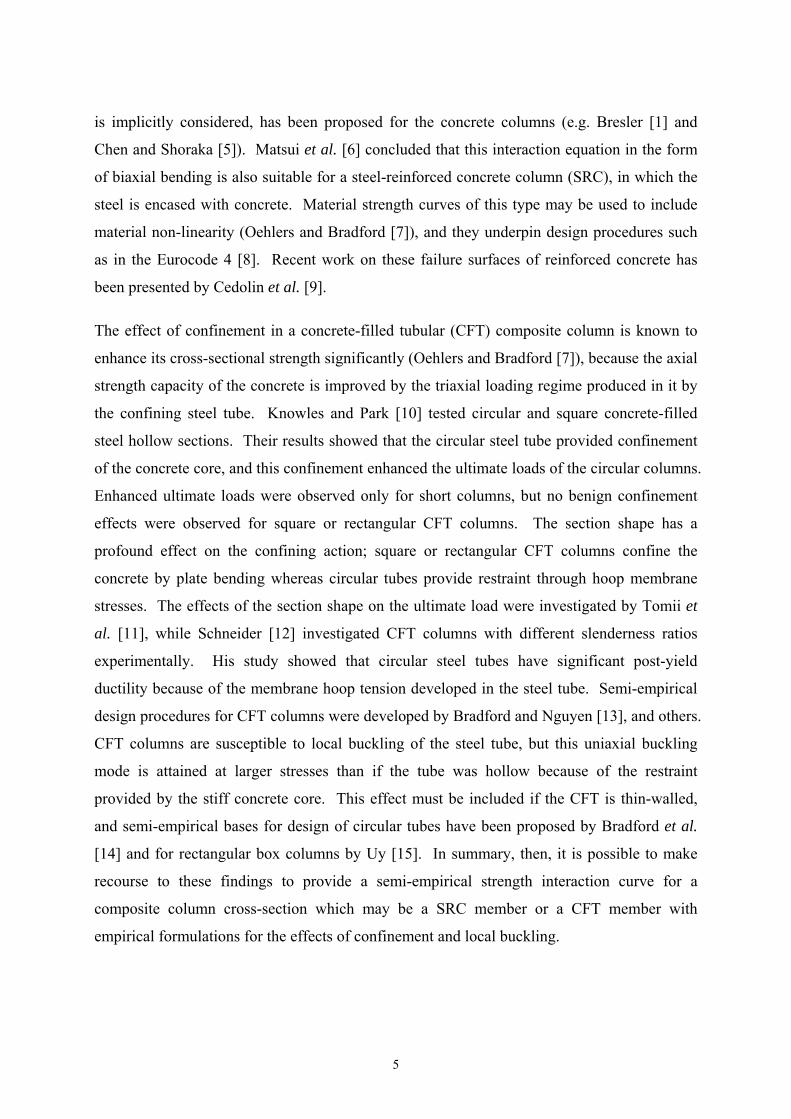
Abstract
Composite steel-concrete structures experience non-linear effects which arise from both
instability-related geometric non-linearity and from material non-linearity in all of their
component members. Because of this, conventional design procedures cannot capture the true
behaviour of a composite frame throughout its full loading range, and so a procedure to
account for those non-linearities is much needed. This paper therefore presents a numerical
procedure capable of addressing geometric and material non-linearities at the strength limit
state based on the refined plastic hinge method. Different material non-linearity for different
composite structural components such as T-beams, concrete-filled tubular (CFT) and steel-
encased reinforced concrete (SRC) sections can be treated using a routine numerical
procedure for their section properties in this plastic hinge approach. Simple and conservative
initial and full yield surfaces for general composite sections are proposed in this paper. The
refined plastic hinge approach models springs at the ends of the element which are activated
when the surface defining the interaction of bending and axial force at first yield is reached; a
transition from the first yield interaction surface to the fully plastic interaction surface is
postulated based on a proposed refined spring stiffness, which formulates the load-
displacement relation for material non-linearity under the interaction of bending and axial
actions. This produces a benign method for a beam-column composite element under general
loading cases. Another main feature of this paper is that, for members containing a point of
contraflexure, its location is determined with a simple application of the method herein and a
node is then located at this position to reproduce the real flexural behaviour and associated
material non-linearity of the member. Recourse is made to an updated Lagrangian
formulation to consider geometric non-linear behaviour and to develop a non-linear solution
strategy. The formulation with the refined plastic hinge approach is efficacious and robust,
and so a full frame analysis incorporating geometric and material non-linearity is tractable.
By way of contrast, the plastic zone approach possesses the drawback of strain-based
procedures which rely on determining plastic zones within a cross-section and which require
lengthwise integration. Following development of the theory, its application is illustrated
with a number of varied examples.
Key Words:

3
Beam-columns; composite members; geometric non-linearity; material non-linearity; plastic
hinge method; initial and full yield surfaces.

4
1. Introduction
Composite structural members and frames which contain steel and concrete components are
designed to best exploit the structural advantages of these two component materials. This
well-known symbiotic structural relationship is utilised widely in contemporary design and
construction solutions worldwide, resulting in stronger and stiffer frames than those afforded
by the counterpart bare steel frame structure. Despite this widespread use of steel-concrete
composite systems, accurate numerical procedures for their analysis and design have not
evolved in the same way as for steel frames, either with or without semi-rigid joints, and as a
consequence it is recognised widely that prescriptive codes of practice possess many
shortcomings when applied to the safe and economical design of composite structures. This
paper is therefore concerned with the development of a robust finite element-based numerical
procedure to model the material and geometric non-linearity in a composite building frame,
both accurately and efficiently.
Many cases of loading on a composite framed building, such as that caused by its self-weight,
imposed live loading, wind loading as well as extreme loads such as fire and earthquake, will
lead to situations for which the concrete will experience compressive stress and to potential
crushing, tensile stress and therefore to cracking, as well as situations for which the steel may
yield, or may buckle in compression. Because a multi-storey composite frame is often
subjected to significant gravity loading as well as lateral loading, it behaves as a sway frame
and so both geometric non-linearity and flexural buckling are of significance. Consequently,
any numerical procedure which claims to replicate the structural behaviour of a real
composite framed building at ultimate loading must account for material non-linearity of the
composite component as a whole, as well as geometric non-linearity of the frame.
It is both simple and convenient to investigate the strength of a composite cross-section under
both axial and bending actions using interaction yield surfaces. Ultimate strength surfaces for
a short reinforced concrete member subjected to biaxial bending moments at a given level of
axial loading were developed in early work by curve fitting of experimental data (e.g. Bresler
[1], Furlong [2], Meek [3], Bradford and Gilbert [4]). It was found that the interaction surface
between axial load and bending at ultimate was complicated and non-linear. The most useful
failure interaction surface in the form of biaxial bending, in which the presence of axial force
5
is implicitly considered, has been proposed for the concrete columns (e.g. Bresler [1] and
Chen and Shoraka [5]). Matsui et al. [6] concluded that this interaction equation in the form
of biaxial bending is also suitable for a steel-reinforced concrete column (SRC), in which the
steel is encased with concrete. Material strength curves of this type may be used to include
material non-linearity (Oehlers and Bradford [7]), and they underpin design procedures such
as in the Eurocode 4 [8]. Recent work on these failure surfaces of reinforced concrete has
been presented by Cedolin et al. [9].
The effect of confinement in a concrete-filled tubular (CFT) composite column is known to
enhance its cross-sectional strength significantly (Oehlers and Bradford [7]), because the axial
strength capacity of the concrete is improved by the triaxial loading regime produced in it by
the confining steel tube. Knowles and Park [10] tested circular and square concrete-filled
steel hollow sections. Their results showed that the circular steel tube provided confinement
of the concrete core, and this confinement enhanced the ultimate loads of the circular columns.
Enhanced ultimate loads were observed only for short columns, but no benign confinement
effects were observed for square or rectangular CFT columns. The section shape has a
profound effect on the confining action; square or rectangular CFT columns confine the
concrete by plate bending whereas circular tubes provide restraint through hoop membrane
stresses. The effects of the section shape on the ultimate load were investigated by Tomii et
al. [11], while Schneider [12] investigated CFT columns with different slenderness ratios
experimentally. His study showed that circular steel tubes have significant post-yield
ductility because of the membrane hoop tension developed in the steel tube. Semi-empirical
design procedures for CFT columns were developed by Bradford and Nguyen [13], and others.
CFT columns are susceptible to local buckling of the steel tube, but this uniaxial buckling
mode is attained at larger stresses than if the tube was hollow because of the restraint
provided by the stiff concrete core. This effect must be included if the CFT is thin-walled,
and semi-empirical bases for design of circular tubes have been proposed by Bradford et al.
[14] and for rectangular box columns by Uy [15]. In summary, then, it is possible to make
recourse to these findings to provide a semi-empirical strength interaction curve for a
composite column cross-section which may be a SRC member or a CFT member with
empirical formulations for the effects of confinement and local buckling.

6
Numerical techniques for simulating the structural response of composite columns have
grown in prominence over the last decade or so. Mirza and Skrabek [16] presented a
numerical model to determine the nominal strength of SRC columns using their moment-
curvature-thrust relationship and moment equilibrium, assuming a deflected shape for the
beam-column element. A similar procedure to incorporate concrete material non-linearity
was used by Bradford and Nguyen [13] and Bradford [17], and for CFT columns by Mursi
and Uy [18]. Hajjar and Gourley [19] presented a detailed plastic zone analysis of short
square CFT columns, validated with experiments, to obtain an accurate representation of the
cross-section strength of a CFT subjected to a combination of biaxial bending and axial
compression.
For investigating the stability of a composite frame, the description of kinematic deformations
for use in a total and an updated Lagrangian formulation is a necessity. Initial studies using a
total Lagrangian formulation (Mallet and Marcal [20], Zienkiewicz and Taylor [21] and Wen
and Rahimzadeh [22]) were made in the development of the numerical approaches for
modelling the geometric non-linearity. To extend his work to model geometric non-linearity
for a beam-column element, Hajjar et al. [23] developed a stiffness-based finite element
approach for CFT composite members using an updated Lagrangian formulation, which was
able to capture the P- and P- geometric non-linearity in a restrained CFT column, as well as
material non-linearity in the form of distributed plasticity and inter-layer slip between the
steel and concrete. Using a displacement-based finite element formulation, Pi et al. [24] [25]
presented a second order inelastic analysis which included the shear force versus slip
relationship derived from empirical data. Material non-linearity was included with a plastic
zone formulation, with a total Lagrangian formulation being adopted in tackling the geometric
non-linear response. This method was shown to be very versatile and accurate for isolated
members, but its plastic zone formulation in a total Lagrangian representation is
comparatively complicated for use in frame structures with many members, and a reason for
the alternative approach adopted in the present paper.
The objective of this study is to present a non-linear inelastic analysis of composite framed
structures so that the complicated non-linear response of the structure can be obtained in an
efficacious fashion. This stiffness-based finite element formulation resorts to a plastic hinge
approach (Iu and Chan [26]) which has previously been implemented for steel frames; the

7
refined plastic hinge has been modified from an inelastic analysis (Iu [27]) of composite
beams, and can be adapted to different arbitrary composite sections in the beam-column
element. Initial and full yield surfaces for both axial and bending effects which act on
composite sections are proposed, which are conservative for the design purposes, and they are
consistent with plastic hinge formulations that appear in design codes (such as Eurocode 4
[8]). This proposed plastic hinge is able to capture the gradual transition from initial yield to
full plasticity under the interaction of axial and bending effects, which describes relationship
between the load and displacement due to material non-linearity. This refined plastic hinge
approach is versatile and adaptive to different kinds of material by using the appropriate
failure surface. It allows for faster and better-controlled convergence than the plastic zone
method. The geometric non-linearity is included with respect to an updated Lagrangian
formulation, for which the geometry of the structure is updated continuously at each iteration.
Following the development of the proposed plastic hinge model for the composite frames, its
accuracy and scope are established with a number of comparative examples. In particular, a
large-scale composite space frame is studied to demonstrate the efficacy of the present
numerical procedures, which is the one of the prime criteria of engineering design.
2. Basic Stiffness Formulation
Second order analysis in a line finite element representation is usually implemented from
Green’s strain tensor t, with reference to the centroidal axis of the element. The element is
assumed to be prismatic with principal axes y and z and a longitudinal axis x; xyz forming a
right handed Cartesian axis system. This longitudinal strain t consists of a linear term
(u/x), non-linear terms (½(v/x)2 and ½(w/x)2) due to member bowing, as well as
bending terms (y2v/x2 and z2w/x2), so that
wzvywvut 2212
21 , (1)
in which u, v and w are the displacements in the x, y and z directions respectively and ( )
( )/x.
In the elastic range within the element in the plastic hinge modelling, the normal stress is
defined in terms of the normal strain t as

8
tE , (2)
and invoking Castigliano’s first theorem of strain energy for the internal strain energy U
produces
tEU δδ , (3)
which may be integrated over the volume (vol) of the element to produce
L
AvolxAEvolEU
tt
00
221
0
dd)d(d
. (4)
By noting that the axes are centroidal, Eqn (4) leads to
LL
yL
zLL
zwEI
zvEI
xwP
xvP
xuEA
U0
2
0
2
0
2
0
2
0
2 d2
d2
d2
d2
d2
, (5)
in which P is the axial force, Iy and Iz are the second moments of area about respective axis.
The plastic hinge approach herein isolates inelastic effects to the member ends, so that it is
elastic with elastic modulus E for x (0, L). The plastic hinge contribution is discussed
subsequently.
The external work done V equals the product of the applied forces and the corresponding
displacements as
fdTV , (6)
in which d and f are column vectors of the displacements and corresponding external applied
forces. The applied load f is assumed to be independent of the displacement d and so is
conservative; this assumption is valid for general structural engineering problems where the
deformations are small enough to not cause large changes of the points of application of the
loads. The external work V is a linear function of the displacement vector d, so that this
component disappears in the derivation of the tangent stiffness (second derivative) for the
structure.

9
The total potential energy for second order elastic analysis is = U – V, so that using Eqs.
(5) and (6) for an element with incremental displacements u, v and w gives
12
1
T
0
2
0
2
0
2
0
2
0
2 d2
d2
d2
d2
d2 k
kk
LLy
Lz
LL
zwEI
zvEI
xwP
xvP
xuEA
fd . (7)
Representing the displacement vector by
T
zzyyxxuu 21212121 d (8)
and integrating the conventional finite element interpolation functions given by
211 uuu ; 22
1221 zz xxv ;
22
1221 yy xxw (9)
where = x/L, the secant stiffness equation may be obtained from
.42
24
42
24
4
4
304
4
30
21
21
21
21
21
21
21
21
21
21
yy
uyz
zz
zzz
yy
yy
zz
zz
k
L
EI
L
EI
PLPLuu
uu
L
EAU
d
(10)
The tangent stiffness matrix may be obtained from
GLtkj
KKKdd
2
, (11)
in which KL and KG are the 6 6 linear and geometric stiffness matrices of an element. The
structural tangent stiffness matrix can then be assembled using
elements
TT
elements
T LNTKTLLLKK teT , (12)
10
in which T is the transformation matrix relating the member forces to the element forces in
the local coordinate system, L is the transformation matrix from local to global coordinates
and N is a matrix introduced to allow for the work done by rigid body movement, which is
neglected in the stiffness formulation based on an updated Lagrangian formulation.
Consequently, the incremental displacements () evaluated from the tangent stiffness include
the rigid body movement, and the geometry of the structure is then updated by accumulation
of both neutral member deformations and rigid body movements.
3. Non-Linear Solution Procedure
A non-linear incremental-iterative procedure is useful for tracing the non-linear equilibrium
path resulting from geometric and material non-linear effects. The incremental-iterative
solution procedure resorts to the constant load method in a Newton-Raphson scheme, as
shown in Fig. 1.
Using a Newton-Raphson formulation, the total potential energy i+1 at the (i+1)-th iteration
can be linearised using the first term in a Taylor expansion. Hence at a solution point,
0ddddd
jj
i
kk
i
k
i 1 , (13)
so that
0ddddd
jj
i
kk
i
k
i UVU. (14)
In Eq. (14),
sik
iUK
d
(15)
is the secant stiffness matrix at the i-th iteration and
Tij
i
kj
i
k
UK
dddd
(16)

11
is the tangent stiffness matrix at this iteration. Equation (14) may therefore be written as
uKuKf Ts , (17)
in which Ksu = i k
kiU d represents the internal member resistances and f is the vector
of the applied loading. The incremental formulation of Eq. (17) is
uKf T , (18)
in which f is a prescriptive load vector or unbalanced force and u is the vector of
incremental displacements due to the load increment and unbalanced force. For a constant
load method, such as the Newton-Raphson technique, f is the same for each load increment
throughout the non-linear solution procedure.
Thus the incremental displacement can then be determined using the tangent stiffness matrix
after this load increment is known, so that
niT
ni fKu 1 , (19)
with the total displacement vector being accumulated by
ni
nni uuu 1 . (20)
The incremental displacements in global coordinates can be transformed to the member
deformations neiu by the transformation matrix LT for mapping global coordinates to local
coordinates. The incremental member resistance in member coordinates neiR can then be
evaluated in local coordinates as
ni
nei uLu T (21)
and
neis
nei uKR , (22)
12
in which Ks is the incremental secant stiffness matrix at neiu . After determination of the
member resistances, the incremental member resistance is accumulated into the total member
resistance vector in global coordinates as
nei
nni RTLRR 1 , (23)
in which T is the transformation matrix from member to global coordinates. The unbalanced
force ni 1f at the second iteration is obtained as
ni
ni
ni Rff 1 , (24)
where nif and n
iR are the total applied load and member resistance vectors at the n-th load
cycle. This incremental procedure is repeated until an equilibrium solution is achieved, or
until divergence is detected.
4. Partial Shear Connection Effects
In common composite building structures, the beam and slab components may not be
connected rigidly, so that relative slip occurs at their interface, leading to a decrease in
strength (partial shear connection effect) and in stiffness (partial shear interaction effect) of
the composite beam relative to the sum of the individual components when they have full
interaction. For composite columns, the axial force usually dominates which leads to
insignificant shear slip at the interface between steel section and concrete. The effect of
partial shear interaction on composite columns is therefore ignored. In the presence of partial
shear interaction between the steel beam and concrete slab, the effective second moment of
area of the composite beam Ieff is using adopted from the the AISC [28] as
sff
fseff II
C
NII , (25)
in which Nf and Cf are respectively the total shear capacity contributed from the shear studs
and total shear capacity in the longitudinal direction from the steel beam or concrete slab,
whichever is less, so the ratio of Nf/Cf can be treated as degree of shear connection, Is and If

13
are the second moment of inertia of steel section and the composite section with full
interaction, respectively.
Similarly, the effective plastic section modulus Seff including partial shear connection can be
expressed as
sff
fseff SS
C
NSS , (26)
in which Ss and Sf are the plastic section modulus of the steel section and the composite
section with full composite action, respectively. The elastic section modulus of steel section
can be expressed as
c
effeff y
IZ or
c
effeff yD
IZ
, (27)
whichever is smaller on the safer side. An elastic stress distribution across the composite
section is therefore ensured. When a composite beam is subjected to both sagging and
hogging moment, the flexural properties of the composite beam are different either side of the
point of contraflexure. Therefore, Eqs. (25) to (27) should be only applied to the composite
beam in either its sagging or hogging moment region. It is also beneficial to assign the
constant section properties to an element in accordance with its moment distributions. The
reduction in the plastic and elastic moment capacities due to the partial shear connection is
accounted for by Eqs. (25) and (27) respectively, which reduce the yield surfaces as discussed
in Section 5; the deterioration of stiffness due to partial shear interaction can be accounted by
Eq. (25) as addressed in Section 6.
5. Implementation of Material Non-Linearity
5.1 Constitutive laws
Normal structural steel behaviour is characterised by a stress-strain representation as in Fig.
2(a), comprising of an elastic range, gradual and full-yielding, and then by a strain hardening
range until eventual fracture. It is commonly assumed that this behaviour is the same for
tension and compression. Herein, the steel is assumed to be isotropic elastic and fully ductile

14
in the elastic range in the direction of longitudinal normal stress. On the other hand, the
stress-strain representation for concrete in compression is usually characterised by an elastic
range, gradual yielding to its ultimate strength and then by material softening until failure, as
shown in Fig. 2(b). In tension, concrete is usually accepted to be elastic-brittle; its tensile
strength is usually neglected in strength design and it is also neglected in the plastic hinge
model of this paper. In the proposed plastic hinge approach, the material behaviour of the
composite section is integrally considered as a whole.
5.2 Cross-section properties
Cross-sectional properties are useful in describing the material behaviour at a section. For
example, the second moments of area Iy, Iz are related to the elastic stiffness of the member,
whilst the elastic section modulus Ze and plastic section modulus Zp are useful for measuring
the bending strength of the member.
The locations of the elastic and plastic neutral axes are needed for determining section
properties related to bending behaviour at the force-displacement relationship and cross-
section strength capacity, respectively. Unfortunately, the determination of their location is
not trivial and obvious, because of the interdependence between the composite section
properties and these neutral axes when concrete section being in tension is neglected. Further,
because of the variety of composite sections encountered in practice, the material non-linear
analysis of a composite cross-section is best tackled numerically. The location of the elastic
and plastic neutral axes and section properties for Iy, Iz and Ze, Zp, respectively, can be
determined iteratively using this well-recognised procedure by invoking the appropriate
stress-strain material curve depending on load state (Sun et al. [29]).
Another approach, which is conceptually different for locating the elastic and plastic neutral
axes, is proposed in this paper. The location of the elastic neutral axis can scrutinize the
minimal condition that yEdA = 0 and the plastic neutral axis from dA = 0; both these
minimal conditions refer to elastic bending and plastic axial force equilibrium conditions,
which depend on constant material properties, such as E and only in lieu of searching the
stress-strain material curve. Figure 3 shows a layering or segmentation of the cross-section
for T-beam, rectangular CFT, SRC and circular CFT sections. Depending on the fineness of
the layering or segmentation, once the neutral axes have been located, the neutral axes remain

15
unchanged under the assumption of the plastic hinge approach that the elastic beam-column
element is elastic through the entire incremental-iterative process. In other words, this
procedure is an optimization process involving no iteration, which is implemented n times
with respect to each layer defined for the composite section. It therefore leads to reliable and
efficient solutions for these locations.
By doing this, the procedure represents the material behaviour integrally with the plastic
hinge formulation instead of sampling each fibre through a section as is needed in the
techniques reliant on the plastic zone formulations. In other words, this numerical procedure
is equivalent to numerical integration in the plastic zone method. The peculiar feature of this
methodology is that the section properties are evaluated merely for either sagging or hogging
moment distribution, and remain unchanged during the iterative-incremental procedure under
assumption of the plastic hinge approach. Hence the member is discretised into two elements
at the point of contraflexure. The detailed methodology and implication of this methodology
is presented in Iu [27].
It is of interest to note that, for a symmetric composite column section, the elastic and plastic
behaviour under sagging and hogging are the same. Hence, the aforementioned numerical
procedure (element discretisation process) is implemented for the composite columns
irrespective of the moment distribution, with no element discretisation being needed at the
point of contraflexure for a composite column
5.3 Material yield surface
The cross-section properties of a composite beam-column section are evaluated with respect
to biaxial bending and axial force resultants separately, but these resultants interact which are
considered by the yield surfaces as depicted in Fig. 4. To allow for the gradual yielding on
the general composite section, the initial yield criterion is required, as it is of significance that
the full plasticity on the composite section generally occurs long after its initial yield.
Unfortunately, less literature has reported the initial yield condition of the composite sections.
A proposed initial yield for the composite section is therefore directly modified from the
initial yield surface of a steel section (King et al. [30]) by simply replacing the composite
section properties, which are characterised linearly and represented empirically by the factor
i(f) given by

16
pyy
yy
pxx
xx
yai M
Mf
M
Mf
P
P
f , (28)
in which fx and fy is shape factor of the composite cross section for the major and minor axis,
respectively, and a, x and y are factor to take residual stress into account for axial effects
and bending effects about major and minor axes, respectively, f=(P, Mx, My) is the vector of
stress resultants.
The full yield failure of a composite section has attracted research activity, as noted
previously. Nevertheless, most of these full yield surface models are complicated to use, and
the axial force effect is considered implicitly through a complex procedure, such as in
Eurocode 4 [8]. To formulate the plastic hinge stiffness conveniently, a simple and
conservative fully yielded surface is postulated for general composite sections, in which the
axial force effect is considered linearly and explicitly as represented by the factor f (f) in
yx n
py
y
n
px
x
yf M
M
M
M
P
P
f . (29)
Initial yielding is defined by the stress resultant set at a cross-section f = (P, Mx, My) such that
i(f) = 1 and full yielding by f(f) = 1; solutions for f such that f(f) > 1 are not admissible in
the procedure unless strain-hardening behaviour is included. The exponents nx and ny depend
on the column dimensions, amount and distribution of longitudinal steel reinforcement and
lateral ties, the stress-strain characteristics of steel and concrete, and the like.
6. Plastic Hinge Formulation
Figure 5 illustrates the bending and axial plastic hinges employed in the current approach.
When the factor i(f) in Eq. (30) at a node exceeds unity, the bending and axial refined plastic
hinge is activated; the stiffness of the axial spring being
a
i
fa L
EAS
1
1
f
f, (30)
and the stiffness of the flexural spring being

17
b
i
fb L
EIS
1
1
f
f, (31)
in which EA/L and EI/L are the elastic axial and flexural stiffnesses of the composite member,
and a and b are strain hardening parameters which can be selected as positive values (Iu
[27]). Both Sa [0, ) and Sb [0, ). These spring stiffnesses are able to represent the
material non-linear response in the load-deformation relationship for the composite section,
including the elastic domain, gradual yielding and the strain hardening response as depicted in
Fig. 6. Hence this refined plastic hinge formulates the elastic-gradual-plastic material model
with the strain-hardening effect in the force state (load-deformation relationship).
It is interesting to remark that the interaction between the bending and axial actions is
incorporated into this refined plastic hinge stiffness Sa and Sb (elastic-gradual-plastic model)
by twofold considerations. First, in the material model, the interaction effects are taken into
account using the initial i(f) and full yield f(f) criteria in Eqs. (30) and (31). This governs
the occurrence of gradual or full material yielding. Second, in the spring stiffness formulation,
the interaction effect by both axial and bending actions can simultaneously influence the
spring stiffness Sa or Sb so as to experience the gradual yielding, which controls the load-
deformation relationship by the gradual stiffness degradation. Eventually, the gradual
yielding behaviour resulting from both compression and bending is accounted for, which is of
significance for composite beam-columns.
The incremental stiffness relationship for the beam-column element in Fig. 5 is
.2
2
1
1
22
223332
231221
11
11
2
2
1
1
e
s
e
s
e
a
bb
bb
bb
bb
a
e
s
e
s
e
a
u
u
SS
SSKK
KSKS
SS
K
S
M
M
M
M
P
P
(32)
When the axial and bending effects are uncoupled, the moment and axial force equilibrium in
Eq. (32) can be considered separately.

18
Because of the insertion of plastic hinges at the ends of the element, additional internal
rotational degrees of freedom (s1 and s2) are introduced, as shown in Fig. 5.
Condensation of an internal freedom in the member, such as Me1 = Me2 = 0, allows Eq. (32)
to be decomposed, producing
2
1
2
1
2
1
2
1
2
1
e
e
b
b
s
s
b
b
s
s
S
S
S
S
M
M
(33)
and
2
1
22221
12111
2
1
2
1
0
0
e
e
b
b
s
s
b
b
SKK
KSK
S
S
. (34)
After matrix condensation as in Eqs. (33) and (34), the incremental rotational deformations of
the beam-column element e1 and e2 can be evaluated from the incremental joint rotations
s1 and s2 from the equation
2
1
2
1
1
22221
12111
2
1
s
s
b
b
b
b
e
e
S
S
SKK
KSK
2
1
1112211
1222221
2
1 1
s
s
bbb
bbb
e
e
SKSKS
KSSKS
K
, (35)
where 2112222111 KKSKSKK ss . Once the incremental rotations at element e are
known from Eq. (35), which includes the material non-linear effect, the incremental moment
resistance of beam-column element can be evaluated Me from elastic element stiffness as
2
1
2221
1211
2
1
e
e
e
e
KK
KK
M
M
2
1
1112211
1222221
2221
1211
2
1 1
s
s
bbb
bbb
e
e
SKSKS
KSSKS
KK
KK
KM
M
. (36)
Equation (36) therefore can be used to determine the member resistance from the rotational
deformations of the joints, and this is equivalent to the incremental secant stiffness

19
formulation of Eq. (10) by expressing the plastic hinge stiffness in local coordinates in the
non-linear solution procedure expressed in Eq. (22).
For axial forces, the incremental stiffness relationship is given by
e
aa
e
aa
e
a
u
u
LEA
S
u
u
K
S
P
P
11
, (37)
where the incremental axial force in the linear axial spring Pa is equal to the axial force in
the beam-column element Pe. The total incremental axial deformation u is equal to the
sum of the incremental axial deformation in the spring ua and in the element ue, and
consequently the axial resistance of the element is
LEA
P
S
Puuu
aba
uLEAS
L
EAS
Pa
a
, (38)
which describes the axial resistance of the element in terms of the axial displacement and so is
equivalent to the secant stiffness for a plastic axial spring.
By back substituting Eq. (35) into Eq. (33), the incremental moment-rotation relationship is
reformulated with respect to the local or nodal coordinate system according to
2
1
3332
2322
11
2
1
s
s
s
s
u
KK
KK
K
M
M
P
, (39)
in which the axial spring stiffness has been superimposed into the formulation, as there is
uncoupling between the axial and bending effects in the element stiffness. In Eq. (39),
a
a
SK
KSK
11
1111 , (40)
20
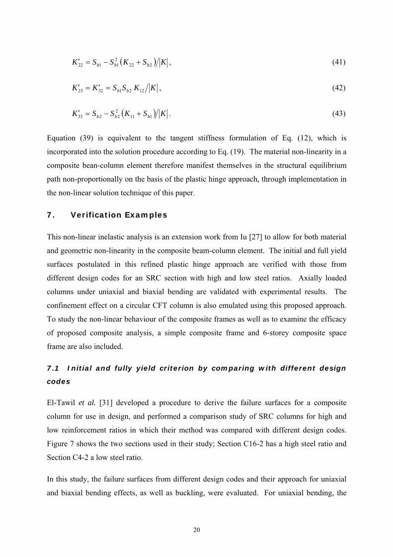
KSKSSK bbb 22221122 , (41)
KKSSKK bb 12213223 , (42)
KSKSSK bbb 11122233 . (43)
Equation (39) is equivalent to the tangent stiffness formulation of Eq. (12), which is
incorporated into the solution procedure according to Eq. (19). The material non-linearity in a
composite bean-column element therefore manifest themselves in the structural equilibrium
path non-proportionally on the basis of the plastic hinge approach, through implementation in
the non-linear solution technique of this paper.
7. Verification Examples
This non-linear inelastic analysis is an extension work from Iu [27] to allow for both material
and geometric non-linearity in the composite beam-column element. The initial and full yield
surfaces postulated in this refined plastic hinge approach are verified with those from
different design codes for an SRC section with high and low steel ratios. Axially loaded
columns under uniaxial and biaxial bending are validated with experimental results. The
confinement effect on a circular CFT column is also emulated using this proposed approach.
To study the non-linear behaviour of the composite frames as well as to examine the efficacy
of proposed composite analysis, a simple composite frame and 6-storey composite space
frame are also included.
7.1 Initial and fully yield criterion by comparing with different design
codes
El-Tawil et al. [31] developed a procedure to derive the failure surfaces for a composite
column for use in design, and performed a comparison study of SRC columns for high and
low reinforcement ratios in which their method was compared with different design codes.
Figure 7 shows the two sections used in their study; Section C16-2 has a high steel ratio and
Section C4-2 a low steel ratio.
In this study, the failure surfaces from different design codes and their approach for uniaxial
and biaxial bending effects, as well as buckling, were evaluated. For uniaxial bending, the

21
comparison of failure surfaces for SRC columns using the approach of El-Tawil et al. [31],
those of different design codes and the present composite analysis are shown in Fig. 8 (for
high steel ratio) and Fig. 9 (for low steel ratio). It can be seen that the proposed initial and
full yield surfaces in the present composite analysis are conservative among those from
different codes. It is suggested that the term for the axial force should not be linear as given
in Eq. (30), especially when the axial force level is low.
For biaxial bending, the comparison of the failure surfaces of a SRC column determined from
different approaches is shown in Fig. 10 and 11 for high and low steel ratios respectively.
Similarly to uniaxial bending, it can also be seen that the proposed initial and full yield
surfaces in the present composite analysis are conservative to predict the material failure for
biaxial bending.
It should be noted that the present non-linear analysis of composite structures allows for
buckling (geometric non-linearity) directly through the numerical procedures, as mentioned in
Sections 2 and 3. When the load increment just reaches the initial and full yield surfaces, the
stress resultants (axial force and bending moments) were measured and plotted in Figs. 12 and
13 for high and low steel ratios respectively. Hence the load increment used in this
comparison study should be as fine as possible in order to ensure the smooth reproduction of
the yield surfaces for stability effect. It is also found that the proposed initial and full yield
surfaces are conservative, especially for the case of the low steel ratio. In summary, the initial
and full yield surfaces for stability effect from the present composite analysis are plotted
under different loading cases, so the contour lines of yield surfaces are discontinuous.
In conclusion, the proposed initial and full failure surfaces are simple and convenient to
formulate the present plastic hinge approach, and also involve no onerous implementation,
such as in design codes (Eurocode 4 [8]).
7.2 Experimental results of square CFT composite column under uniaxial
bending
Bridge [32] reported experimental results for eight slender square CFT composite columns
subjected to uniaxial bending. His columns SHC-1 and SHC-2 under concentric and eccentric
end compressive loading, respectively, were analysed by the numerical technique of this

22
paper, and their geometry and material properties are also shown in Fig. 14. Figure 15 shows
the load versus deflection plots for the two columns, in which it can be seen that the plastic
hinge-based numerical procedure replicates the experimental response well, especially for the
column which displays flexural buckling behaviour, and so is able to capture both geometric
and material non-linearity when subjected to the uniaxial bending.
7.3 Experimental results of steel encased concrete section under biaxial
bending
Virdi and Dowling [33] presented experimental results for nine SRC columns subjected to
biaxial bending and compression. The cross-section used is shown in Fig. 16 and the nine
specimens were divided into three batches of constant length; each batch of constant length
had different eccentric compression producing different biaxial bending moments. One batch
of length 732 mm (columns G, H and I) was analysed using the numerical procedure herein,
with the material properties including the yield strength of the steel section and cube strength
of the concrete being given in Virdi and Dowling [33]. The elastic modulus of the steel was
taken as 200 kN/mm2.
The load versus mid-height deflection of columns G, H and I are shown in Fig. 17, which
compares the present numerical solutions with the tests of Virdi and Dowling [33]. This
paper does not report the elastic modulus of the concrete (which is quite variable in nature)
and a modular ratio of 6.8 was used for the numerical results of column G only to correlate
the elastic modulus of the concrete, whereas the other columns H and I use modular ratio of
15.
The values of different concrete elasticity are chosen without loss of accuracy, since three
column specimens were of the same sections and member lengths but subjected to an axial
compression load with linearly proportional eccentricities. As a natural result, the elastic
flexural behaviour of three specimens should be also linear proportion, if and only if the
elastic modulus of these columns was same, which governs the behaviour in elastic range.
However, from the observation of their experimental results, the mid-height load-deflection
curves of the column G did not vary linearly from the other columns H and I, but those of the
columns H and I varied linearly accordingly. Thus, it is strongly reasonable that the elastic
modulus of column G was different from other two specimens. It can be seen from Fig. 17

23
that the agreement between test and theory is generally good. Therefore, the present
composite analysis can capture the geometric and material non-linearity of the composite
columns when subjected to the biaxial bending.
7.4 Experimental and numerical results of circular CFT section under
axial load
It is well-known that when concrete is confined, as in a circular CFT composite column, its
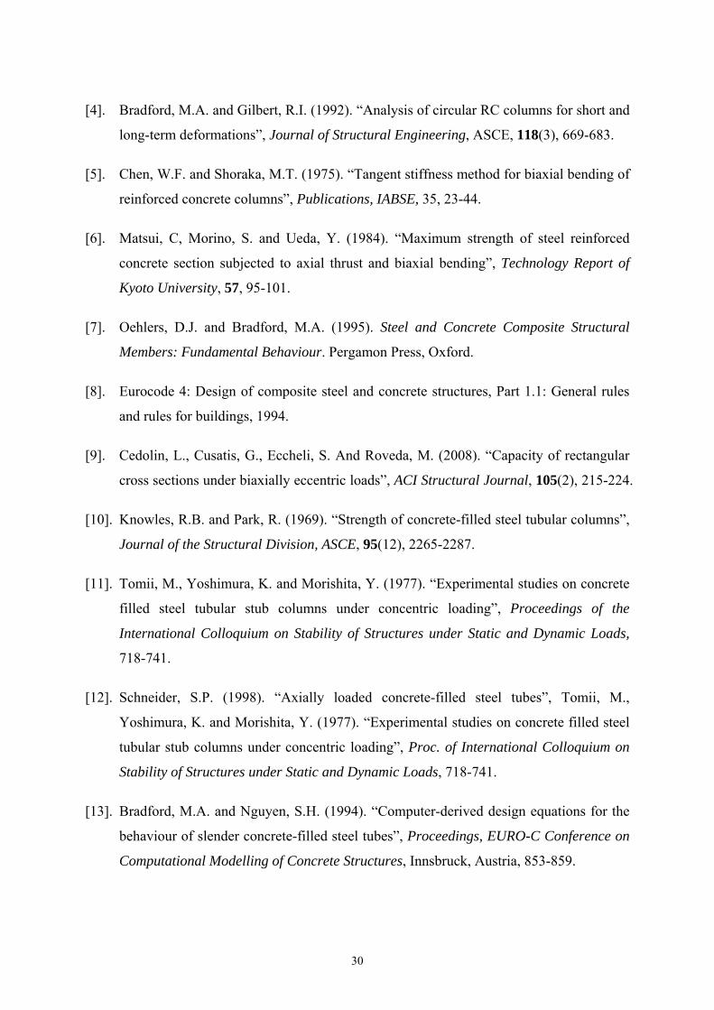
overall compressive strength increases because of the effect of the confinement. Schneider
[12] conducted tests on 14 CFT specimens which were all loaded axially in compression;
three were of circular, five of square and six of rectangular tubular steel section. The results
from one of the tests (C1) are shown in Fig. 18, with the material and section properties used
in the numerical studies being obtained from Schneider [12].
The axial response from the numerical model is reasonably consistent with that of the
experimental results, as well as the numerical results of Schneider [12]. However, the
ultimate load of the circular CFT column from the present analysis without considering
confinement effect is less than the results of Schneider [12]. To account for the confinement
effect, the section properties as mentioned in Section 4 can be proportionally enhanced with
respect to the concrete section. Therefore, the axial deformation is also plotted using the
present model with a 50% enhancement for the concrete as result of the confinement; this
produces an upper bound on the axial load versus deflection plot. It should be noted that the
effects of confinement of the concrete are dependent on the complex triaxial state of stress
that develops; this enhancement can reduce with increasing load and disappears altogether
with the onset of local buckling of the tube. However, the proposed approach simplifies the
post-yield response of confinement effect by the constant strain-hardening parameter in the
plastic hinge spring stiffness, which is independent of the stress state, so the enhancement of
the cross-section strength of a circular specimen increases proportionally reliant on the
present composite analysis.
7.5 Numerical results for a simple composite frame
24
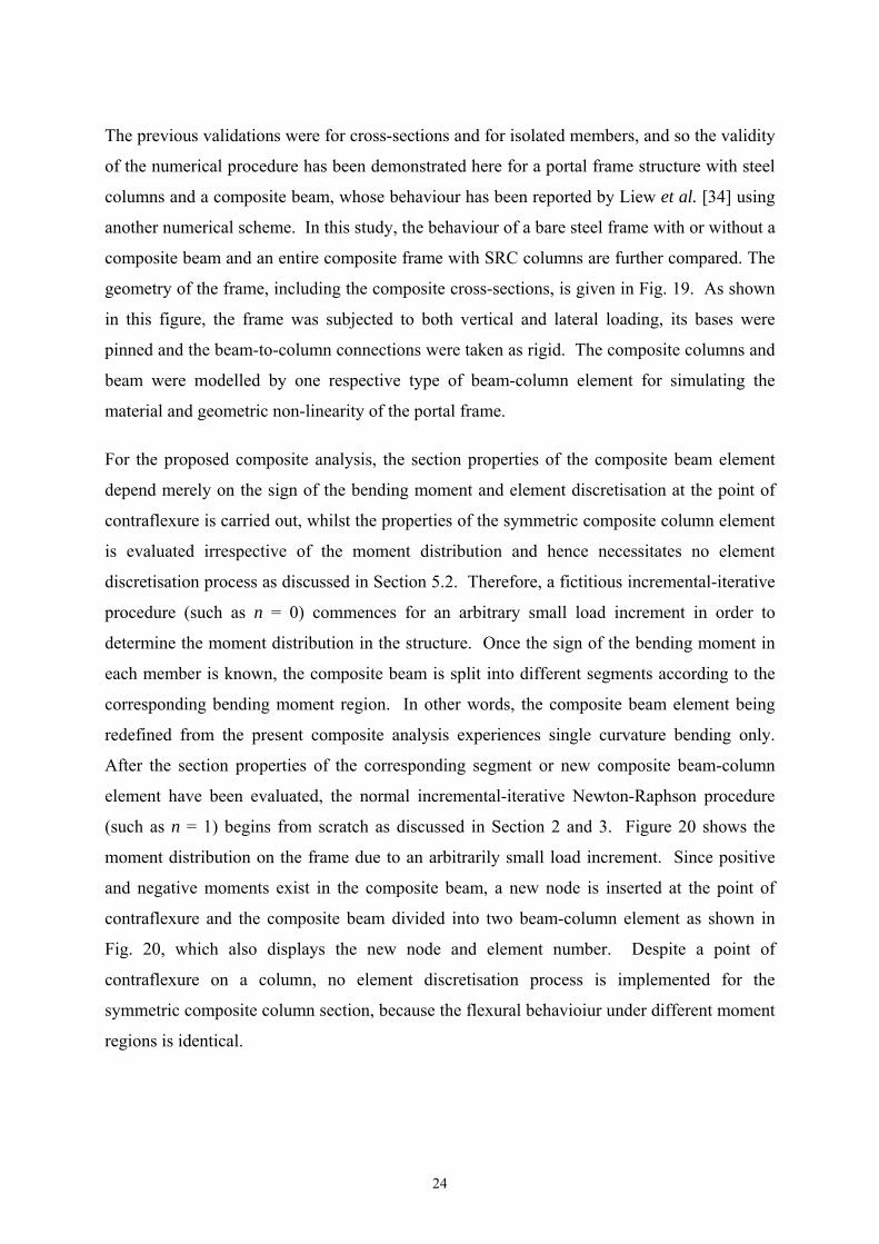
The previous validations were for cross-sections and for isolated members, and so the validity
of the numerical procedure has been demonstrated here for a portal frame structure with steel
columns and a composite beam, whose behaviour has been reported by Liew et al. [34] using
another numerical scheme. In this study, the behaviour of a bare steel frame with or without a
composite beam and an entire composite frame with SRC columns are further compared. The
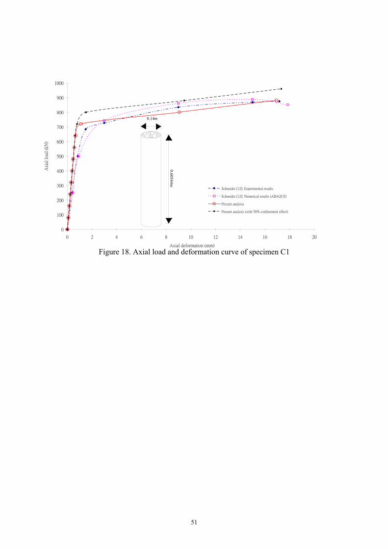
geometry of the frame, including the composite cross-sections, is given in Fig. 19. As shown
in this figure, the frame was subjected to both vertical and lateral loading, its bases were
pinned and the beam-to-column connections were taken as rigid. The composite columns and
beam were modelled by one respective type of beam-column element for simulating the
material and geometric non-linearity of the portal frame.
For the proposed composite analysis, the section properties of the composite beam element
depend merely on the sign of the bending moment and element discretisation at the point of
contraflexure is carried out, whilst the properties of the symmetric composite column element
is evaluated irrespective of the moment distribution and hence necessitates no element
discretisation process as discussed in Section 5.2. Therefore, a fictitious incremental-iterative
procedure (such as n = 0) commences for an arbitrary small load increment in order to
determine the moment distribution in the structure. Once the sign of the bending moment in
each member is known, the composite beam is split into different segments according to the
corresponding bending moment region. In other words, the composite beam element being
redefined from the present composite analysis experiences single curvature bending only.
After the section properties of the corresponding segment or new composite beam-column
element have been evaluated, the normal incremental-iterative Newton-Raphson procedure
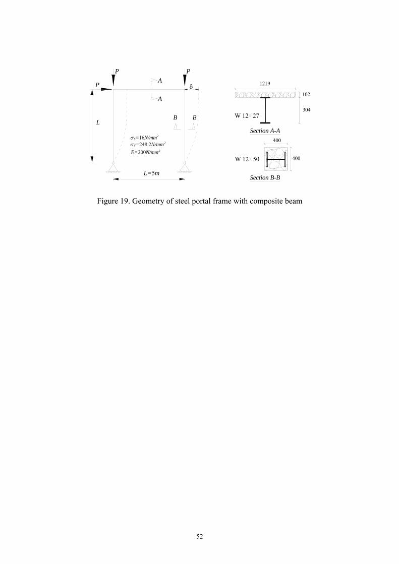
(such as n = 1) begins from scratch as discussed in Section 2 and 3. Figure 20 shows the
moment distribution on the frame due to an arbitrarily small load increment. Since positive
and negative moments exist in the composite beam, a new node is inserted at the point of
contraflexure and the composite beam divided into two beam-column element as shown in
Fig. 20, which also displays the new node and element number. Despite a point of
contraflexure on a column, no element discretisation process is implemented for the
symmetric composite column section, because the flexural behavioiur under different moment
regions is identical.

25
According to Liew et al. [34], the flexural stiffness of the composite beam should be
approximated by using Ic. On the other hand, no approximate flexural stiffness of the
composite beam-column element is necessary in the present analysis to capture overall
composite beam behaviour, since all section properties are evaluated in accordance with the
rigorous procedure as mentioned in Section 5.2. The centroidal locus of the two columns and
composite beam is plotted in Fig. 21 according to the sign of moment region.
In this verification, no strain hardening is included. A mechanism then develops when both
fully-yielded hinges are formed at beam-column joints at which no further member resistance
is possible for resisting additional loading. The gradual yielding, which is of significance on
the composite member in general, is included in the material model of this study.
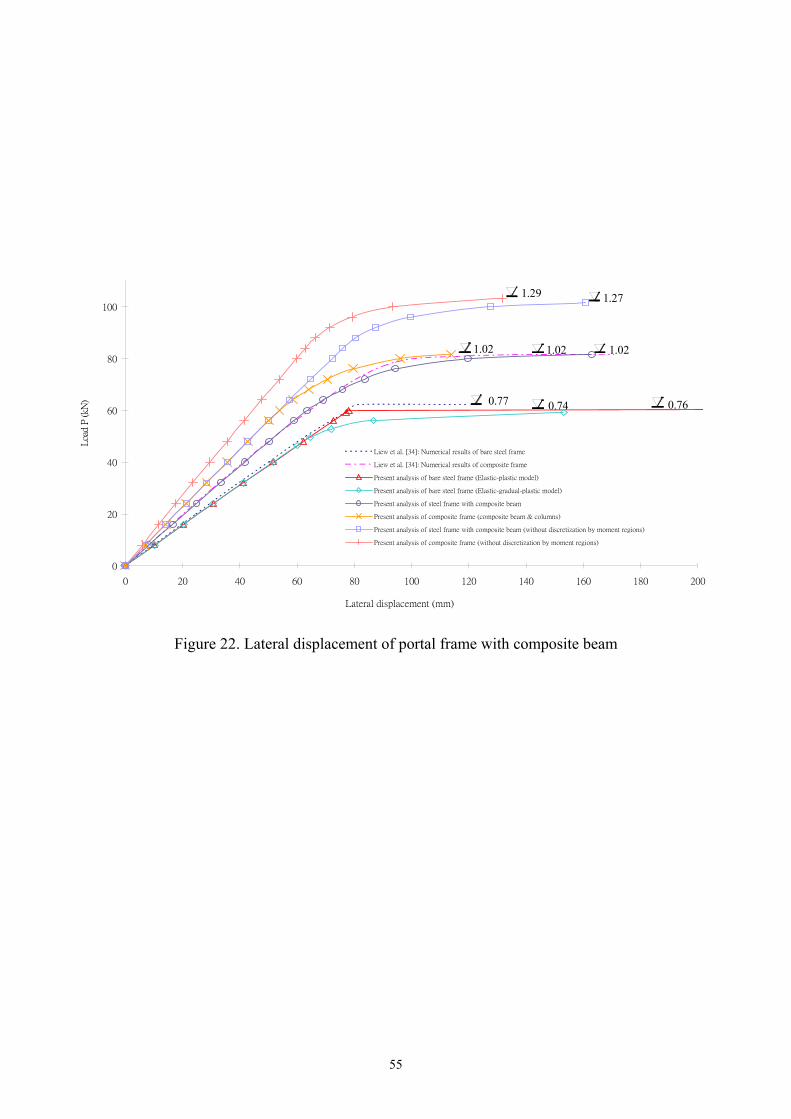
The behaviour of the horizontal displacement under the vertical and lateral load P was
studied in this numerical example, and is plotted in Fig. 22. The ultimate load factor of a bare
frame from Liew et al. [34] is 0.7775. In the present analysis, the ultimate loads factor of the
corresponding frame under elastic-plastic and elastic-gradual-plastic material model are
respectively 0.76 and 0.74 as indicated in Fig. 22. Further, the lateral displacement of a steel
frame with composite beam predicted from the present analysis is in good agreement with the
numerical results of Liew et al. [34] generally. The first initial yielded plastic hinge appears
at node 3 (steel beam to steel column connection) at about load factor of 0.75. Subsequently,
both fully yielded plastic hinge springs at both beam-to-column joints are activated till the
occurrence of numerical divergence at load factor of 1.02, which is coincident with the
ultimate load from Liew et al. [34]. In summary, the ultimate strength of this composite
frame is enhanced by 38% above that of the bare frame.
For the frame with both a composite beam and columns, its ultimate strength against sway is
identical at 1.02, but the lateral stiffness of the composite frame is larger than that of steel
frame with a composite beam. This implies that the composite columns contribute little
lateral load capacity but the stiffness of lateral stability, because the composite column section
cannot considerably enhance the strength capacity of the beam-to-column joint, particularly in
the hogging moment region. This is a crucial structural component to the lateral load capacity
of the frame.

26
Before further discussion of differences between the present composite analysis and
traditional composite design, it is of interest to briefly review the practical composite design
procedure in general for which the composite sections are evaluated and applied for the whole
composite member; linear elastic analysis is executed to determine loading distribution on the
composite structures. According to the linear elastic frame analysis, the ultimate strength of
the composite frame is obtained complying with codified composite design criteria for both
geometric and material non-linearity.
Without element discretisation at the point of contraflexure on a composite beam, the ultimate
loads of a composite frame with steel or composite columns are also higher in the consistent
manner as given in Fig. 22, which overstates both the ultimate strength and, the lateral
stiffness. Unfortunately, this process is normal design practice for composite member or
frame, and consequently yields an unsafe ultimate strength design of the composite structure
without onerous design criteria. It is therefore concluded that the proposed composite
analysis can robustly replicate the real behaviour at ultimate of a composite frame accurately,
even without the approximate flexural stiffness used in Liew et al. [34]. In this study, all
significant geometric and material non-linearities composite structures are directly and
numerically tackled through the proposed numerical procedure, which leads to a safe
composite design for the ultimate strength of the composite frames in the efficacious manner.
7.6 Numerical results for a six-storey composite space frame
In addition to a simple composite plane frame and isolated members, a rigid-jointed 6-storey
asymmetrical steel space frame has been modified and included in this verification as given in
Fig. 23, which was originally analysed by Orbison et al. [35] in 1982 and later studied by
Liew et al. [36] and Jiang et al. [37]. More recently, this large-scale steel frame has been
analysed to validate a higher-order element formulation associated with refined plastic hinge
approach by Iu and Bradford [38] [39]. This example converts the frame to a composite open
frame with the intent to demonstrate the efficacy of the present numerical procedures and to
verify the behaviour of a large-scale composite space frame using the present composite
analysis.
The steel beams in the frame rigidly support the concrete floor slab, and the steel columns are
encased partially in the concrete for fire protection, whose sections are also given in Fig. 23.
27
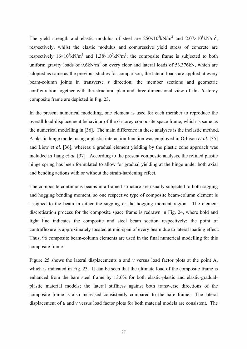
The yield strength and elastic modulus of steel are 250103kN/m2 and 2.07108kN/m2,
respectively, whilst the elastic modulus and compressive yield stress of concrete are
respectively 16103kN/m2 and 1.38107kN/m2; the composite frame is subjected to both
uniform gravity loads of 9.6kN/m2 on every floor and lateral loads of 53.376kN, which are
adopted as same as the previous studies for comparison; the lateral loads are applied at every
beam-column joints in transverse z direction; the member sections and geometric
configuration together with the structural plan and three-dimensional view of this 6-storey
composite frame are depicted in Fig. 23.
In the present numerical modelling, one element is used for each member to reproduce the
overall load-displacement behaviour of the 6-storey composite space frame, which is same as
the numerical modelling in [36]. The main difference in these analyses is the inelastic method.
A plastic hinge model using a plastic interaction function was employed in Orbison et al. [35]
and Liew et al. [36], whereas a gradual element yielding by the plastic zone approach was
included in Jiang et al. [37]. According to the present composite analysis, the refined plastic
hinge spring has been formulated to allow for gradual yielding at the hinge under both axial
and bending actions with or without the strain-hardening effect.
The composite continuous beams in a framed structure are usually subjected to both sagging
and hogging bending moment, so one respective type of composite beam-column element is
assigned to the beam in either the sagging or the hogging moment region. The element
discretisation process for the composite space frame is redrawn in Fig. 24, where bold and
light line indicates the composite and steel beam section respectively; the point of
contraflexure is approximately located at mid-span of every beam due to lateral loading effect.
Thus, 96 composite beam-column elements are used in the final numerical modelling for this
composite frame.
Figure 25 shows the lateral displacements u and v versus load factor plots at the point A,
which is indicated in Fig. 23. It can be seen that the ultimate load of the composite frame is
enhanced from the bare steel frame by 13.6% for both elastic-plastic and elastic-gradual-
plastic material models; the lateral stiffness against both transverse directions of the
composite frame is also increased consistently compared to the bare frame. The lateral
displacement of u and v versus load factor plots for both material models are consistent. The

28
first yield of the frame occurs at the load factor of 0.77 and 0.97 for the elastic-gradual-plastic
and elastic-plastic models, respectively. In line with the previous results of [39], the twisting
behaviour of the composite structure is observed due to the asymmetric structural plan, which
leads to the asymmetric lateral loads.
The present composite analysis accounting for both geometric and material non-linearity is
efficacious, as it takes 10 seconds to complete the numerical analysis of this composite space
frame for over 100 load cycles on a modest personal computer.
8. Concluding Remarks
This paper has proposed a composite beam-column element which can successfully
incorporate both material and geometric non-linearity into its formulation. The inelastic
element is based on a refined plastic hinge spring at its ends, which can model the gradual
yielding from initial to full yield under the axial and bending interaction effect. Thus, the
elastic-gradual-plastic with strain-hardening material model in terms of a load-displacement
relation is included in the present analysis for composite structures. On the contrary, for the
alternate plastic zone method, the yield surfaces for the interaction of bending and axial force
are formulated in terms of stress resultants in deference to stresses which produce
computational inefficiencies and which render such stress-based approaches difficult for the
modelling of full structural frames. The refined plastic hinge model is versatile and adaptive
to different kinds of material, when the corresponding initial and full yield surfaces are used
in the spring stiffness formulation. As a result, the present approach is useful in its
incorporation of maternal non-linearity in composite beam-columns, because it captures
inelastic buckling caused by the interaction of geometric and material non-linearity in the
proposed refined plastic hinge approach. The method also allows for easy incorporation of
bending about both axes as well as axial force, so that three dimensional frame analyses can
be undertaken.
The approach herein implements a procedure for evaluating the section properties to represent
the member cross-section strength capacity in line with numerical integration used in the
plastic zone method. This procedure can be carried out robustly for any arbitrary cross-
section in general, including composite T-beams, SRC and CFT columns with or without
conventional reinforcement. Since members may, in general, be subjected through their

29
length to positive and negative bending so that they experience different material behaviour as
well as flexural behaviour, an adaptive-type element is used in which an additional node is
located at the point of contraflexure of the bending composite beams. The inelastic element
with end plastic hinges enables replication of the corresponding material non-linearity of
either positive or negative bending; a fictitious incremental-iterative procedure is therefore
carried out to determine the moment distribution under an arbitrarily small load increment.
This simple discretisation process leads the present composite analysis to a precise estimation
of the flexural behaviour of a composite beam. Ultimate strength analyses of composite
frames are therefore achieved through both the element discretisation process and the refined
plastic hinge approach. Finally, the present analysis was validated with the models of single
members, frames and large-scale composite building structures, in which shows the present
approach was shown to be accurate, effective and reliable.
In conclusion, the proposed composite analysis is not only reliant on the refined plastic hinge
approach, which is capable of evaluating the cross-section strength capacity of a whole
structure, but also it is based on the non-linear solution procedures as mentioned in Sections 2
and 3, which directly and numerically solve the geometric non-linearity of general composite
frames. It provides a platform for robust and efficacious design applications of general
frames with arbitrary composite sections at the strength limit state.
Acknowledgements
The work in this paper was supported by the University of Hawaii and by the Australian
Research Council through its Federation Fellowship Scheme.
References
[1]. Bresler, B. (1960). “Design criteria for reinforced concrete columns under axial load
and biaxial bending”, ACI Journal, 57(5), 481-490.
[2]. Furlong, R.W. (1961). “Ultimate strength of square columns under biaxial eccentric
load”, ACI Journal, 59(9), 1129-1140.
[3]. Meek, J.L. (1963). “Ultimate strength of columns with biaxially eccentric load”, ACI
Journal, 60(8), 1053-1064.
30
[4]. Bradford, M.A. and Gilbert, R.I. (1992). “Analysis of circular RC columns for short and
long-term deformations”, Journal of Structural Engineering, ASCE, 118(3), 669-683.
[5]. Chen, W.F. and Shoraka, M.T. (1975). “Tangent stiffness method for biaxial bending of
reinforced concrete columns”, Publications, IABSE, 35, 23-44.
[6]. Matsui, C, Morino, S. and Ueda, Y. (1984). “Maximum strength of steel reinforced
concrete section subjected to axial thrust and biaxial bending”, Technology Report of
Kyoto University, 57, 95-101.
[7]. Oehlers, D.J. and Bradford, M.A. (1995). Steel and Concrete Composite Structural
Members: Fundamental Behaviour. Pergamon Press, Oxford.
[8]. Eurocode 4: Design of composite steel and concrete structures, Part 1.1: General rules
and rules for buildings, 1994.
[9]. Cedolin, L., Cusatis, G., Eccheli, S. And Roveda, M. (2008). “Capacity of rectangular
cross sections under biaxially eccentric loads”, ACI Structural Journal, 105(2), 215-224.
[10]. Knowles, R.B. and Park, R. (1969). “Strength of concrete-filled steel tubular columns”,
Journal of the Structural Division, ASCE, 95(12), 2265-2287.
[11]. Tomii, M., Yoshimura, K. and Morishita, Y. (1977). “Experimental studies on concrete
filled steel tubular stub columns under concentric loading”, Proceedings of the
International Colloquium on Stability of Structures under Static and Dynamic Loads,
718-741.
[12]. Schneider, S.P. (1998). “Axially loaded concrete-filled steel tubes”, Tomii, M.,
Yoshimura, K. and Morishita, Y. (1977). “Experimental studies on concrete filled steel
tubular stub columns under concentric loading”, Proc. of International Colloquium on
Stability of Structures under Static and Dynamic Loads, 718-741.
[13]. Bradford, M.A. and Nguyen, S.H. (1994). “Computer-derived design equations for the
behaviour of slender concrete-filled steel tubes”, Proceedings, EURO-C Conference on
Computational Modelling of Concrete Structures, Innsbruck, Austria, 853-859.

31
[14]. Bradford, M.A., Loh, H.Y. and Uy, B. (2002). “Slenderness limits for filled circular
steel tubes”, Journal of Constructional Steel Research, 58(2), 243-252.
[15]. Uy, B. (2000) “Strength of concrete filled steel box columns incorporating local
buckling”, Journal of Structural Engineering, ASCE, 126(3), 341-352.
[16]. Mirza, S.A. and Skrabek, B.W. (1992). “Statistical analysis of slender composite beam-
column strength”, Journal of Structural Engineering, ASCE, 118(5), 1312-1322.
[17]. Bradford, M.A. (2005). “Shrinkage and creep response of slender reinforced concrete
columns under moment gradient: theory and test results”, Magazine of Concrete
Research 57(4), 235-246.
[18]. Mursi, M. and Uy, B. (2004). “Strength of slender concrete filled high strength steel box
columns”, Journal of Constructional Steel Research, 60(12), 1825-1848.
[19]. Hajjar, J.F. and Gourley, B.C. (1996). “Representation of concrete-filled steel tube
cross-section strength”, Journal of Structural Engineering, ASCE, 122(11), 1327-1336.
[20]. Mallet, R.H. and Marcal, P.V. (1968). “Finite element analysis of nonlinear structures”,
Journal of the Structural Division, ASCE, 94(9), 2081-2105.
[21]. Zienkiewicz, O.C. and Taylor, R.L. (1971), The Finite Element Method, Vol. 2, 2nd
Edition, McGraw-Hill Book Co., New York.
[22]. Wen, R.K. and Rahimzadeh, J. (1983), “Nonlinear elastic frame analysis by finite
element”, Journal of Structural Engineering, ASCE, 109(8), 1952-1971.
[23]. Hajjar, J.F., Schiller, P.H. and Molodan, A. (1998). “A distributed plasticity model for
concrete-filled steel tube beam columns with interlayer slip”, Engineering Structures,
20(18), 663-676.
[24]. Pi, Y.-L., Bradford, M.A. and Uy, B. (2006). Second order nonlinear inelastic analysis
of composite steel-concrete members. I: Theory”, Journal of Structural Engineering,
ASCE, 132(5), 751-761.

32
[25]. Pi, Y.-L., Bradford, M.A. and Uy, B. (2006). Second order nonlinear inelastic analysis
of composite steel-concrete members. II: Applications”, Journal of Structural
Engineering, ASCE, 132(5), 762-771.
[26]. Iu, C.K. and Chan, S.L. (2004). “A simulation-based large deflection and inelastic
analysis of steel frames under fire”, Journal of Constructional Steel Research, 60, 1495-
1524.
[27]. Iu, C.K. (2008). “Inelastic finite element analysis of composite beam on the basis of
plastic hinge approach”, Engineering Structures (in press).
[28]. American Institute of Steel Construction (AISC). (1993). Load and resistance factor
design specifications. 2nd Ed., Chicago.
[29]. Sun, S.C.H., Bradford, M.A. and Gilbert, R.I. (1994). “A reliable numerical method for
simulating the post-failure behaviour of concrete frame structures”, Computers and
Structures 53(3), 579-589.
[30]. King, W.S., White, D.W. and Chen, W.F. (1992). “On second-order inelastic analysis
methods for steel frame design”, Journal of Structural Engineering, ASCE, 118(2), 408-
428.
[31]. El-Tawil, S., Sanz-Picon, C.F. and Deierlein, G.G. (1995). “Evaluation of ACI 318 and
AISC (LRFD) strength provisions for composite beam-columns”, Journal of
Constructional Steel Research, 134, 103-123.
[32]. Bridge, R.Q. (1976). "Concrete filled steel tubular columns" Civil Engineering
Transactions, Institution of Engineers, Australia, 18, 127-133.
[33]. Virdi, K.S. and Dowling, P.J. (1973). “The ultimate strength of composite columns in
biaxial bending”, Proceedings of the Institution of Civil Engineers Part. 2, 55, 251-272.
[34]. Liew, J.Y.R., Chen, H. and Shanmugam, N.E. (2001). “Inelastic analysis of steel frames
with composite beams”, Journal of Structural Engineering, ASCE, 127(2), 194-202.
[35]. Orbison, J.G., McGuire, W. and Abel, J.F. (1982), “Yield surface applications in

33
nonlinear steel frame analysis”, Computer Methods in Applied Mechanics and
Engineering, 33(1), 557-573.
[36]. Liew, J.Y.R., Chen, H., Shanmugam, N.E. and Chen, W.F. (2000), “Improved nonlinear
plastic hinge analysis of space frame structures”, Engineering Structures, 22, 1324-1338.
[37]. Jiang, X.M., Chen, H. and Liew, J.Y.R. (2002), “Spread of plasticity analysis of three-
dimensional steel frames”, Journal of Constructional Steel Research, 58, 193-212.
[38]. Iu, C.K. and Bradford, M.A. (2008), “Higher-order nonlinear analysis of steel structures
Part I: Elastic second-order formulation”, (to be submitted).
[39]. Iu, C.K. and Bradford, M.A. (2008), “Higher-order nonlinear analysis of steel structures
Part II: Refined plastic hinge method”, (to be submitted).

34
Figure 1. Incremental-iterative scheme of Newton-Raphson method
nf
1nf 1 nf
nf
1nf
Displacement
Loa
d
ni 1u n
iu
1nu
12 n
iu11 n
iu1 niu
nu
niR
1nR
12 n
iR11 n
iR1 niR
nR
Displacement
Loa
d

35
Figure 2. Stress-strain representation of material behaviour
cuf
cuf
(a) Steel material (b) Concrete material
plastic plateau strain hardening
elastic limit
Elasticlimit strain strain
stress stress
plasticlimit
EcE s

36
Figure 3. Segmentation of composite cross-sections
x1 x2 x3
y1
y2
y3
x1 x2 x3 x4 x5
Nc Nf Nw Nf Nc
Nc
Nf
Nw
Nf
Nc
Nf
Nw
Nf
CFT column Concrete core
Steel tube
Nw
Nw
x1
x2 x3 x4 x5 x6 x7
y1 y2 y3 y4
y5 y7 Reinforcement
Nc
Nt
Nw
Nb
y1 y2 y3 y4 y5

37
Figure 4. Yield surfaces of composite cross-section in terms of axial and biaxial bending
stress resultants
1
yn
py
yxn
px
x
yf M
M
M
M
P
P
1pyy
yy
pxx
xx
yai M
Mf
M
Mf
P
P
P
Mx
My

38
Figure 5. Composite beam-column element with axial and rotational springs
ai
f
L
EA
1
1
bi
f
L
EI
1
11e1sau
eu
2e 2s
bi
f
L
EI
1
1
2sM
1sM2eM
1eMeP
aP S b1
S b2
LS a

39
Deformation
Loa
d
Gradualyielding
Elastic
Es
Strain-hardening effect
Figure 6. Material behaviour in plastic hinge formulation in terms of load-deformation axes

40
660.4
660.4
50140.1
140.1
140.1
140.150
889
889
50
197.25
197.25
197.25
197.25
50W14 176 (16 No. 8)
W14 370 (16 No. 6)
(High steel ratio) (Low steel ratio)
Figure 7. Section, dimension and reinforcement pattern of SRC columns

41
-5000
0
5000
10000
15000
20000
25000
30000
0 500 1000 1500 2000 2500 3000 3500 4000 4500
Moment M (kNm)
Axi
al f
orce
P (
kN)
COSBIAN
ACI-Ult.
AISC-Ult.
EURO-Ult.
ACI-design
AISC-design
EURO-design
Present analysis
Figure 8. C16-2 specimen under uniaxial bending (high steel ratio)

42
-5000
0
5000
10000
15000
20000
25000
30000
0 500 1000 1500 2000 2500 3000 3500 4000 4500
Moment (kNm)
Axi
al f
orce
(kN
)
COSBIAN
ACI-Ult.
AISC-Ult.
EURO-Ult.
ACI-design
AISC-design
EURO-design
Present analysis
Figure 9. C4-2 specimen under uniaxial bending (low steel ratio)

43
-5000
0
5000
10000
15000
20000
25000
30000
0 500 1000 1500 2000 2500 3000
Moment M (kNm)
Axi
al f
orce
P (
kN)
COSBIAN
ACI-Ult.
AISC-Ult.
ACI-design
AISC-design
Present analysis
Figure 10. C16-2 specimen under biaxial bending (high steel ratio)

44
-5000
0
5000
10000
15000
20000
25000
30000
0 500 1000 1500 2000 2500 3000
Moment M (kNm)
Axi
al f
orce
P (
kN)
COSBIAN
ACI-Ult.
AISC-Ult.
ACI-design
AISC-design
Present analysis
Figure 11. C4-2 specimen under biaxial bending (low steel ratio)

45
0
5000
10000
15000
20000
25000
30000
0 500 1000 1500 2000 2500 3000 3500 4000 4500
Moment M (kNm)
Axi
al f
orce
P (
kN)
COSBIAN (L/r=0)
COSBIAN (L/r=40)
ACI (L/r=40)
AISC (L/r=40)
EURO (L/r=40)
Present analysis (initial yield surface)
Present analysis (full yield surface)
Figure 12. C16-2 specimen subjected to buckling effect (high steel ratio)

46
0
5000
10000
15000
20000
25000
30000
0 500 1000 1500 2000 2500 3000 3500 4000
Moment M (kNm)
Axi
al f
orce
P (
kN)
COSBIAN (L/r=0)
COSBIAN (L/r=40)
ACI (L/r=40)
AISC (L/r=40)
EURO (L/r=40)
Present analysis (initial yield surface)
Present analysis (full yield surface)
Figure 13. C4-2 specimen subjected to buckling effect (low steel ratio)

47
Figure 14. Section and dimension of test specimen of the square CFT column
Steel (kN/m2) Concrete (kN/m2)
Elastic modulus 2.05108 2.33107 Steel yield stress/
Concrete compressive strength 2.91105 3.02104 20
00
P
200mm
200mm
e
10mm

48
0
500
1000
1500
2000
2500
3000
3500
0 2 4 6 8 10 12 14
Deflection at mid-height (mm)
Loa
d Q
(kN
)
Bridge [32]: SHC-1
Bridge [32]: SHC-2
Present analysis: SHC-1
Present analysis: SHC-2
Figure 15. Square CFT columns under uniaxial bending compared with tests

49
152
50.8
50.8
152 50.850.8
25.4
UC 152 152 23
12
v
u
Figure 16. Section, dimension and axes of SRC column

50
0
100
200
300
400
500
600
700
800
0 20 40 60 80 100 120 140 160
Deflection (mm)
Loa
d Q
(kN
)
Virdi and Dowling [33] (Column G)
Virdi and Dowling [33] (Column H)
Virdi and Dowling [33] (Column I)
Present analysis (Column G)
Present analysis (Column G)
Present analysis (Column H)
Present analysis (Column H)
Present analysis (Column I)
Present analysis (Column I)
Figure 17. Experimental SRC columns G, H and I under biaxial bending
51
Figure 18. Axial load and deformation curve of specimen C1
0
100
200
300
400
500
600
700
800
900
1000
0 2 4 6 8 10 12 14 16 18 20
Axial deformation (mm)
Axi
al loa
d (k
N)
Schneider [12]: Experimental results
Schneider [12]: Numerical results (ABAQUS)
Present analysis
Present analysis (with 50% confinement effect)
0.14m
0.60544m
52
L=5m
L
P P
P
A
A 1219
102
304W 12 27
Section A-A
E=200N/mm
y=248.2N/mm2
2
c=16N/mm2
B B
Section B-B
W 12 50 400
400
Figure 19. Geometry of steel portal frame with composite beam
53
19.9kNm 19.9kNm
1
2 3
4
5
1 3
42
(2.5072 , 5)
Figure 20. Element discretisation process according to moment distribution under arbitrary small load increment

54
Figure 21. Compatibility condition of the portal frame
41b
32b
31b2
2b
21b
12b
32b
41b
32s
41s
41
32 ss where
55
Figure 22. Lateral displacement of portal frame with composite beam
76.074.077.0
02.1 02.1
29.1 27.1
02.1
0
20
40
60
80
100
0 20 40 60 80 100 120 140 160 180 200
Lateral displacement (mm)
Loa
d P (
kN)
Liew et al. [34]: Numerical results of bare steel frame
Liew et al. [34]: Numerical results of composite frame
Present analysis of bare steel frame (Elastic-plastic model)
Present analysis of bare steel frame (Elastic-gradual-plastic model)
Present analysis of steel frame with composite beam
Present analysis of composite frame (composite beam & columns)
Present analysis of steel frame with composite beam (without discretization by moment regions)
Present analysis of composite frame (without discretization by moment regions)

56
W 12 26 W 12 53 W 12 87
W 10 60W 12 120W 12 87
1000mm
125mm
1000mm 1000mm
7.315m 7.315m
7.31
5m
W12 26W12 26
W12 26W12 26
W12
53
W12
87
W12
53
6 @
3.6
85m
=21
.948
m
W12
87W
1060
W10
60
W10
60
W12
87
W12
120
W12
120
W10
60
W12
87
W12
87
Point A
y
xz
Wind loaddirection
u
v
Figure 23. Configuration and member sections of a 6-storey composite space frame

57
Figure 24. Element discretisation of 6-storey composite frame

58
0
0.2
0.4
0.6
0.8
1
1.2
1.4
‐320 ‐270 ‐220 ‐170 ‐120 ‐70 ‐20
Lateral displacement (mm)
Load factor
L iew et al. [36] (R efined plas tic hinge method)
J iang et al. [37] (P las tic zone method)
Iu and Bradford [38] [39] (Higher‐order analys is of s teel s tructures )
P resent analys is (R efined plas tic hinge method of compos ite s tructures ) [elas tic‐plas tic]
P resent analys is (R efined plas tic hinge method of compos ite s tructures ) [elas tic‐gradual‐plas tic]
Figure 25. Lateral drifts of points A and B in x- and z-directions vs load factor
17.1
03.1
16.1 17.1
03.1
16.1
uv