c certainteed installation guide - buildsite.com · important information warranties these...
TRANSCRIPT

Cer ta inTeed
Viny l and Polymer Sid ing
certainteed corporation
P.o. Box 860
Valley forge, Pa 19482
Professional: 800-233-8990
consumer: 800-782-8777
www.certainteed.com
ASK ABOUT OUR OTHER CERTAINTEED PRODUCTS AND SYSTEMS:
code no. ctS205, © 10/10 certainteed corporation, Printed in u.S.a.
ExtErior: roofing • Siding • WindoWS • fEncE • railing • trim • dEcking • foundationS • PiPE
intErior: inSulation • gyPSum • cEilingS
Ce
rta
inTe
ed
Vin
yl a
nd
Po
lym
er S
idin
g In
sta
llatio
n G
uid
eC
TS
205
Installation Guide

Important Information
Warranties
These instructions describe and illustrate the stepsinvolved in installing CertainTeed and Wolverine siding, trim, and accessories. Their purpose is toprovide detailed information and how-to tips that will simplify the installation process. CertainTeed shall not accept any liability or responsibility under its written warranty for failure caused by applicationthat does not meet the requirements for properinstallation. These requirements are outlinedthroughout this book. Any deviations from theserequirements should be addressed and approved in writing by CertainTeed Corporation.
In rare incidents, intense sunlight reflected fromglass on vinyl siding may create heat buildup andcause the siding to distort. To help minimize theeffects of heat buildup from reflected sun, thehomeowner may take one or more of the following measures:
• Install a screen in the window causing the problem.
• Install an awning over the window to break the line of light reflection.
• Use shrubbery to protect the area of siding from reflections.
Building codes and regulations vary throughout the country. Be sure to check with your local code official or governing body for the buildingrequirements in your area.
Important Fire Safety Information
Exterior vinyl building materials require littlemaintenance for many years. Nevertheless, commonsense dictates that builders and suppliers of vinylproducts store, handle and install vinyl materials in a manner that avoids damage to the product and/orthe structure. Owners and installers should take a few simple steps to protect vinyl building materialsfrom fire:
• To Home and Building Owners: Rigid vinylsiding is made from organic materials and willmelt or burn when exposed to a significantsource of flame or heat. Building owners,occupants and outside maintenance personnelshould always take normal precautions to keep sources of fire, such as barbecues, andcombustible materials, such as dry leaves, mulch and trash, away from vinyl siding.
• To the Building Trades, Specifiers,Professionals and Do-It Yourself Installers:When rigid vinyl siding is exposed to significantheat or flame, the vinyl will soften, sag, melt orburn, and may thereby expose materialunderneath. Care must be exercised whenselecting underlayment materials because manyunderlayment materials are made from organicmaterials that are combustible. You shouldascertain the fire properties of underlaymentmaterials prior to installation. All buildingmaterials should be installed in accordance with local, state and federal building codes and fire regulations.
CertainTeed Vinyl Siding Installation Guide
This manual shows the basic guidelines for installation. It is based on ASTM (American Society for Testing and Materials) D4756, thestandard practice for installation of vinyl siding and soffit. Additionally, we recommend that local building codes be reviewed.
1

2
CertainTeed Vinyl Siding Installation Guide
The CertainTeed Master Craftsman program is your opportunityto earn valuable rewards while maintaining a leg up on yourcompetition. These rewards are not available to everyone, justto those who have successfully passed the Master CraftsmanEducation and Development test.
As a Master Craftsman, you are entitled to:
n Receive a personalized Certificate of Completion that you can use to promote your professional services.
n Be listed as a Master Craftsman on our contractor locatorwebsite, where potential customers can find you. The listingwill include your name, company name, phone number, e-mail address, and a link to your website if you have one.
n Have access to the Master Craftsman website, whichincludes Building Solutions® program information, industrynews and information, and product and installation updates.
For more information about the CertainTeed Master Craftsman program, call
800-233-8990or log on to
www.certainteed.com
Enter the “Professional” site, click “Contractor,” and then clickon the Master Craftsman icon.
Become a CertainTeed Master Craftsman

3
CertainTeed Vinyl Siding Installation Guide
Table of Contents
3
SECTION 1 — Introduction .........................................4
SECTION 2 — Materials and ToolsSiding Terms..............................................................................5Starter Strips..............................................................................6J-Channels and F-Channels .....................................................8Utility Trim ..................................................................................9Miscellaneous Accessories.....................................................10Lineal Options..........................................................................11Cornerposts.............................................................................12Equipment and Tools ..............................................................13Transporting and Storing Vinyl Siding ....................................14Special Tools............................................................................15
SECTION 3 — EstimatingSiding.......................................................................................16Measuring ................................................................................18Estimating Form ......................................................................19
SECTION 4 — Preparing for Horizontal SidingPreparing Wall Surfaces..........................................................20Nailing, Stapling and Other Fastening Methods....................23Expansion and Contraction ....................................................25Installing Accessories..............................................................26Outside Cornerposts...............................................................27Extra Wide Cornerposts..........................................................29Inside Cornerposts..................................................................30Federal Corners.......................................................................31Inside Federal Corners............................................................32Bay Window Corners ..............................................................33Decorative Trim Options around Windows and Doors..........34Window Flashing.....................................................................35Window and Door Trim ...........................................................36Snap-on Lineals ......................................................................37Lineal Starter Application
for Windows and Door Surrounds..................................39Lineal Application around Windows.......................................40Lineals over Horizontal Siding ................................................43Corner Blocks..........................................................................445" Square Header with Endcaps
over 3-1/2" Lineals Sides and Bottoms .........................45Creating End Caps for 5" Lineals ...........................................46Slip Joints for Lineal Corners..................................................47Crown Molding Treatment Options ........................................48Crown Molding and Cap for 3/4" Pocket J-Channel ............49Crown Molding with 3-1/2" Lineal Surround .........................49Crown Molding with Cap for 5" Header Lineal......................50Band Board .............................................................................52Blind Miter................................................................................53Lineal Frieze Board..................................................................54Finishing with Cornice Molding and Receiver .......................55Installing J-Channel as Gable End Trim .................................56Using Lineals as Gable Trim ...................................................57Restoration Millwork Trim .......................................................58
SECTION 5 — Installing Horizontal SidingTop Ten Tips for Installing Vinyl Siding...................................60Cutting Panels .........................................................................61Overlapping Panels .................................................................61STUDfinder™ Installation System ..........................................62Preparing Wall Surfaces..........................................................63Completion ..............................................................................69Shutter Installation...................................................................70
SECTION 6 — Installing Vertical Siding (including Board & Batten)Preparing Wall Surfaces..........................................................71Cornerposts.............................................................................72Top and Bottom J-channel .....................................................72J-channel at Gable Ends ........................................................73Wall Panels ..............................................................................74Gable End Panels....................................................................76
SECTION 7 — Porch Ceilings, Soffit, FasciaRequirements for Proper Soffit Ventilation.............................77Porch Ceilings .........................................................................78Soffit.........................................................................................80Triple 3-1/3 Solid and InvisiVent Soffit....................................83Fascia.......................................................................................84
SECTION 8 — Installing Specific CertainTeed ProductsD7 Straight Edge Perfection Shingles....................................87T5 Straight Edge Perfection Shingles ...................................89D9 Staggered Rough-Split Shakes .......................................92D7 Straight Edge Rough-Split Shakes...................................94D7 Staggered Perfection Shingles .........................................96Cornice Cap with Cedar Impressions
Mitered Cornerpost .........................................................98Cedar Impressions Inside Cornerpost .................................100Bay Window Cornerposts.....................................................101Half-Round Shingles .............................................................102Half-Round Shingles in Gable Ends.....................................106Cedar Impressions on a Steep Rake ...................................109Cedar Impressions in Non-vertical Walls .............................109Starting Cedar Impressions with Lineals
over Horizontal Siding ...................................................110Starting Cedar Impressions
over Horizontal Siding ...................................................111Application of Half-Round Shingle under Soffit...................112Special Effects with Cedar Impressions ..............................113Replacing a Damaged Cedar Impressions
Panel with the Repair Kit (Option 1)..............................114Replacing a Damaged Cedar Impressions Panel
(Option 2) .......................................................................117Northwoods S7" and S9" Shakes .......................................118Northwoods S10" Shakes ....................................................121CedarBoards Insulated Siding..............................................124
SECTION 9 — Special SituationsTrimming Curved Openings..................................................130Frieze Board ..........................................................................131Decorative Sunbursts............................................................131
SECTION 10 — RepairReplacing a Damaged Siding Panel.....................................134Replacing a Damaged Outside Cornerpost.........................134Repairing Buckled Siding at the Joist ..................................135
SECTION 11 — MiscellaneousCleaning Vinyl Siding.............................................................136Siding Over Asbestos ...........................................................137Historic Restoration...............................................................137For More Information ............................................................138
INDEX..........................................................................139

Introduction
Plan your work, then work your plan.
That’s the key to success with any project, and it’s doubly true when it comes to installing vinyl siding, soffit, trim and accessories.
If you use the right materials and the right tools in the rightorder, you’ll complete remodeling and new home installationsin less time, with less effort, and with far greater satisfaction.
Since you’re using CertainTeed products, you’ve already takenthe first step toward success. CertainTeed sidings, soffit, trimand accessories provide premium quality, rugged durabilityand outstanding appearance. Quite simply, they’re made tolook great–on the day they’re installed and for years after.
The second ingredient of success–using the proper tools,techniques and procedures–is covered in this book. As you’llsee by scanning the table of contents, this book guides youthrough every step of the installation process, from estimatingmaterials to attaching mailboxes and shutters. Every majorinstallation project is covered: horizontal; vertical, includingBoard & Batten; soffit and fascia; porch ceilings; and decora-tive trim. Where various approaches to a particular installationprocedure are possible, the book presents practical alterna-tives. To make the instructions as detailed and complete aspossible, dozens of illustrations accompany the text.
As you’re reading–and while you’re working–keep in mind the most important rule of thumb for successful vinyl sidinginstallation: allow for movement. All vinyl siding, soffit andaccessories used in exterior applications must be able tomove freely as they expand and contract with temperaturechanges. You’ll see this point emphasized again and againthroughout this book; you’ll also learn various techniques formeasuring, fitting and nailing that will allow this unobstructedmovement. These are perhaps the most important lessons inthis booklet.
NOTE: No instruction book can anticipate all thequestions that might arise during a siding or soffitinstallation. Recognizing this, we’ve focused on the toolsand techniques used to complete typical installations.Where appropriate, we’ve also included alternativeapproaches for specific installation steps. If you encountera unique installation problem not covered in this book, wesuggest you contact your building materials distributor orcall our Sales Support Group at 1-800-233-8990.
4
Section 1 — IntroductionCertainTeed Vinyl Siding Installation Guide

5
CertainTeed Vinyl Siding Installation Guide
SECTION 2 — Materials and Tools
rake
verticalsiding
gabledormer
soffit
fascia
siding
outsidecornerpost
insidecornerpost
Siding Terms
Nail Flange
Common to most vinyl siding products (includes horizontaland vertical sidings, soffits and most accessories).
Lock
Common to most vinyl siding products (includes horizontaland vertical sidings, soffits and some accessories).
Panel Projection
Common to products with multiple faces (i.e. Double 4 orTriple 3). It is the dimension required for the proper selection of receiving channels (e.g., J-channels and corner pieces).
Butt Leg / Locking Leg
Common to most vinyl siding products that lock into oneanother (e.g., siding into starters or siding panels into siding panels).

CertainTeed Vinyl Siding Installation Guide
6
Starter Strips
2-1/4" Vinyl Starter Strip
Secures the first course of siding to the home. For use with all sidings except Monogram® 46, Monogram® 46L,CedarBoards, CedarBoards XL, and Cedar Impressions.
2-1/2" Metal Starter Strip
For use with all sidings except CedarBoards and CedarImpressions.
5" Metal Starter Strip
Designed to be used on remodeling jobs to help level the firstcourse and span areas that cannot be nailed. For use with allsidings except CedarBoards and Cedar Impressions.
4" Metal Starter Strip
4" metal starter to be used with Cedar Impressions.
Starter Strip for Insulated Siding
Vinyl starter strip that accommodates 1-1/4" thickness ofinsulated siding.

CertainTeed Vinyl Siding Installation Guide
7
Corner Starter Strip
Secures 3-1/2" and 5" lineals and quarter round insert tocreate a 4-piece corner.
New Construction Window and Door Starter
Butts up against protruding window and door jambs andoverhangs for installation of 3-1/2" and 5" lineals.
Remodeling Window and Door Starter
Holds 3-1/2" and 5" lineals in place around window and dooropenings. Used in re-siding applications where existingcasings have not been removed.
CertainTeed Vinyl Siding Installation Guide
8
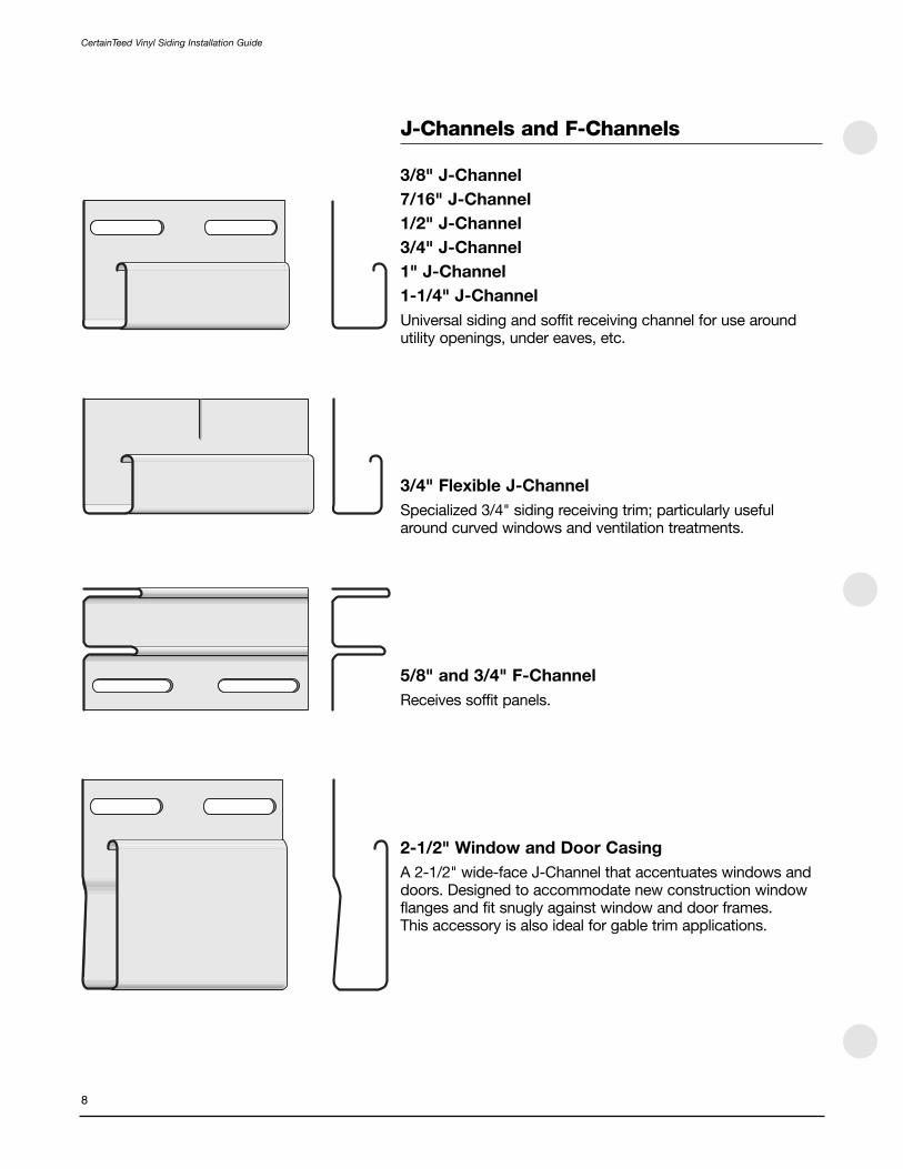
J-Channels and F-Channels
3/8" J-Channel
7/16" J-Channel
1/2" J-Channel
3/4" J-Channel
1" J-Channel
1-1/4" J-Channel
Universal siding and soffit receiving channel for use aroundutility openings, under eaves, etc.
3/4" Flexible J-Channel
Specialized 3/4" siding receiving trim; particularly usefularound curved windows and ventilation treatments.
5/8" and 3/4" F-Channel
Receives soffit panels.
2-1/2" Window and Door Casing
A 2-1/2" wide-face J-Channel that accentuates windows anddoors. Designed to accommodate new construction windowflanges and fit snugly against window and door frames. This accessory is also ideal for gable trim applications.

CertainTeed Vinyl Siding Installation Guide
9
Utility Trim
Undersill Trim
Helps secure trimmed siding panels under windows and eaves.
Dual Undersill Trim
Secures trimmed siding panels under windows and eavesregardless of the profile or where in the panel face the panelhas been trimmed.
Cornice Molding Receiver
Installed under eaves to hold the Cornice Molding in place.Does not receive soffit panels.
Cornice Molding
Held in place by the F-channel or Cornice Molding Receiver,this accessory hides the installation of the topmost sidingpanels. With the help of a nail slot punch, topmost sidingpanels can be installed with nails every time. Can also be used under windows. Great for use with Cedar Impressionsand Restoration Shapes.
Vinyl Fascia
Installed with F-channel and Undersill Trim to provide avirtually maintenance-free fascia board.

CertainTeed Vinyl Siding Installation Guide
10
Miscellaneous Accessories
Crown Molding
Used in conjunction with 5" lineals to create a custom molded window or door header. Can also be used with 3-1/2"lineals and 3/4" pocket J-channels. Crown has a 2-1/4" topexposed edge.
Crown Molding Cap
Caps the ends of a crown molding with minimal cutting.
NOTE: Shown already cut in half – one piece makes a leftand right-end cap.
Cornice Molding Cornerpost Cap
Used to cap Cornice Molding over Mitered Cornerposts.
Soffit Cove Trim(Shown as if secured to trusses or soffit nailers.)
A decorative soffit receiver featuring a 9/16" receiving pocket.
(Shown as if attached to wall substrate. This profile can alsobe used as an inside cornerpost. Will not work for all profiles.)
Aluminum Trim Coil
24"-wide PVC-coated aluminum.
Drip Cap
Acts as a flash over windows and doors.

3/8" H-bar1/2" H-bar
Joins soffit panels. Particularly useful on porch ceilings and hiproof applications.
3-1/2" Double Channel Lineal5" Double Channel Lineal
Exposure matches 3-1/2" window and door surround lineals.
Lineal Options
3-1/2" Lineal
For use with a New Construction Window and Door Starteraround windows and doors as a casing. The 3/4" channelreceives siding panels. Can also be used as a cornerpost.
5" Lineal
Two lineals create a corner system when installed with aCorner Starter and corner insert. Can also be used with awindow starter strip as a window/door casing. The 3/4"channel receives siding panels.
Quarter Round Insert
Installed with a Corner Starter and lineals as a decorativecorner treatment.
Band Board
7-1/4" decorative trim used with CedarBoards, CedarImpressions Rough-Split Shakes, and Northwoods.
Corner Block
Used with 3-1/2" lineals to finish corners around windows and doors.
Rosette
Attaches to Corner Block as a decorative treatment.
3-1/2" Snap-on Lineal
Used with J-channel.
CertainTeed Vinyl Siding Installation Guide
11

CertainTeed Vinyl Siding Installation Guide
12
Cornerposts
Outside Cornerposts
3/4" Outside Cornerpost – Woodgrain and Matte7/16" Outside Cornerpost – Woodgrain1" Outside Cornerpost – Woodgrain1-1/4" Outside Cornerpost – Woodgrain with Foam Insert
The 3/4" cornerpost can be used with all sidings exceptCedarBoards, D9" Rough-Split Shakes, and Northwoods. The 1" cornerpost may be used with D9 Rough-Split andNorthwoods. The 1-1/4” cornerpost is used with CedarBoardsand Cedar Impressions Rough-Split Shakes.
3/4" Inside Cornerpost – Matte and Woodgrain
Used where siding meets at inside corners; provides a finished look.
1-1/4" Inside Cornerpost – Matte
Use with CedarBoards, Cedar Impressions Rough-SplitShakes, and Northwoods.
Fluted SuperCorner
Fluted corner design with foam backing.
3/4" and 1-1/4" Traditional SuperCorner
Wide decorative traditional corner treatment with foambacking. The 1-1/4” is used with CedarBoards, CedarImpressions Rough-Split Shakes, and Northwoods.
Beaded SuperCorner
Wide decorative beaded corner treatment with a foam backing and optional beaded insert.
Mitered Cornerposts
Corner treatment for use with Cedar Impressions.
3/4" SuperCorner – Beaded and Fluted
Bay Window Cornerpost
Adapts to odd angles of bay windows.
5" Corner Cap
Used to create corner systems.

Equipment and Tools
Fasteners
Use only corrosion-resistant nails (aluminum, stainless orgalvanized roofing.) Nails should have a minimum headdiameter of 5/16". Staples should be a minimum of 16 gauge.
If screws are used, use non-corrosive, self-tapping, pan heador washer head screws or oval head with countersunk washerscrews with at least 5/16" diameter head, 1/8" (3mm) diametershaft, and at least 1-1/8" (29mm) long.
To determine the length of nail required, measure the thicknessof the sheathing material. Then add at least 3/4" to allow thenail to penetrate the solid wood substrate (studs or existingwood siding). For more secure fastening, add 1" to sheathingthickness. The minimum nail size should be 1-1/2".
Example: If you’re applying siding over 1/2" sheathing, use a nail at least 1-1/2" long (1/2" sheathing + 3/4” studpenetration + nailing hem thickness + minimum 1/16" between nailing hem and fastener head).
To determine the quantity of nails required, complete the following:
Total square feet of siding required: ___________
(if using aluminum nails) x .005(if using galvanized roofing nails) x .01
Pounds of nails required: = ___________
For nailing instructions, see page 23 to 25.
Tools Required
Hammer Tin snips Tape measure SquareChalk line Level Utility knife Shears
Power circular saw with sharp, fine-tooth plywood blademounted in reverse direction.
Ladders and scaffolds
NOTE: If you will be using an extension ladder duringinstallation, be sure to cushion the upper side rails to help prevent damage to installed siding.
Cutting table
Portable brake
Essential for bending aluminum trim coil to fit around fasciaboards, window sills, window and door casings, etc. Pleaserefer to the brake manufacturer’s instructions for metalbending techniques.
CertainTeed Vinyl Siding Installation Guide
13

CertainTeed Vinyl Siding Installation Guide
14
Transporting and Storing Vinyl Siding
CertainTeed’s standard shipment method incorporatespalletizing and stretch wrapping all products.
• The pallet is a double-faced, reversible, Grade M, SPEQ®-certified pallet constructed of quality materials that meet NWPCA Uniform Voluntary Standards (Sec. 5.1, Table 1).
• Customer racking should be at least 46" deep x 157" longto accommodate CertainTeed pallets.
• Do not store pallets by more than three units high.
• Vinyl and polymer siding should be stored indoors andaway from direct sources of heat and sunlight. Storingproducts outside may result in damage.
If you are transporting vinyl siding to a job site, make certainto keep cartons flat and supported along their entire length.
At the job site, take the following precautions when storing panels:
• Store on a flat surface and support the entire length of the carton.
• Keep cartons dry.
• Store away from areas where falling objects or otherconstruction activity may cause damage.
• Do not store in any location where temperatures mayexceed 130° F (e.g., on black top pavement duringunusually hot weather, under dark tarps or plastic wrapswithout air circulation, or in unventilated storage trailers).

Special Tools
Nail Slot Punch (57997)
Punches elongated holes to allow nailing the cut edge of a panel. Also used to enlarge an existing hole to allowproper nailing.
Snap Lock Punch (57995 or 57996)
Punches tabs in the cut edge of a panel used as a finishingcourse at the top of a wall or underneath a window. The tabslock into undersill trim. For best results, we recommend usingitem 57995 Snap Lock Punch, which is designed specificallyfor vinyl applications.
Zip Tool (57998 or 57999)
Locks and unlocks panels.
CertainTeed Vinyl Siding Installation Guide
15
Cut off anddiscard

Section 3 — EstimatingCertainTeed Vinyl Siding Installation Guide
16
Siding
Use the illustrations and formulas below and enter totals onthe estimating form in this section. These formulas apply forboth horizontal and vertical installations.
NOTE: When estimating for a large project, you may wantto add a waste allowance of 10 percent to the totals forsiding, soffit and accessories.
Rectangular wall surfacesMeasure height (excluding gables). Measure width (including doors and windows).
_____________ x _____________ = _____________(height) (width) (surface area)
Repeat for remaining walls.
Triangular gable end surfacesMeasure height at center (add 1' to allow for waste). Measure width and divide by half.
_____________ x _____________ = _____________(height) (1/2 width) (surface area)
Repeat for remaining gables.

Upper wall of gambrel houseDivide the upper wall of a gambrel house as shown in theillustration. Then use the following formulas:
1/2 (B + C) x H = ____________
1/2 C x D = ____________
Add these figures to get total area: ____________
Repeat for remaining gambrel surfaces.
Dormer sidesMeasure height of dormer (add 1' to allow for waste). Use thefollowing formula:
_____________ x _____________ = ____________________(1/2 height) (1/2 width) (surface area, 1 side)
____________________ x 2 = _________________________(surface area, 1 side) (total dormer surface area)
Repeat for all dormers.
SoffitMeasure width of eave to be covered. Measure length of eave.
_____________ x _____________ = _____________(width) (length) (surface area)
Repeat for remaining eaves.
Porch CeilingMeasure length of porch area to be covered. Measure width ofporch.
_____________ x _____________ = _____________(length) (width) (surface area)
CertainTeed Vinyl Siding Installation Guide
17

CertainTeed Vinyl Siding Installation Guide
18
Measuring
Before ordering accessories, you also have to determine thewidth of the J-channel into which you will fit the vinyl siding.To do this, you must first determine which of two methods youwill use to apply sheathings or underlayments. This is coveredin more detail under “Sheathings.”
NOTE: Refer to product catalog for product accessoryrecommendations and availability.
Starter strip: Measure along base of building. _________
J-channel: For siding installations, measure around doors and windows, under eaves, at rake edges of gables where dormer meets roofline, and anywhere else required to provide a finished appearance. _________
For soffit, measure along wall under eave and along fascia board. _________
For porch ceilings, measure along perimeter of the porch area. _________
F-channel: For soffit, measure along wall under eve. _________
For porch ceilings, measure along perimeter of the porch area. _________
3-1/2" and 5" lineals: For casing, measure along perimeter of doors and windows. For gables, measure at rake edges of gables where dormer meets roof line. _________
Undersill trim: Measure above and below windows and above doors and top course of siding below soffit. _________
Soffit H-bar: Measure diagonals at all eave corners. _________
Outside cornerpost: Measure length ofoutside corners. _________
Inside cornerpost: Measure length ofinside corners. _________
NOTE: If you plan to use J-channel instead of insidecornerposts, remember to double this measurement and add the total to your entry for J-channel.
Dual undersill trim: Measure along top of wall where siding will meet eaves. _________

CertainTeed Vinyl Siding Installation Guide
19
Estimating Form
Siding Walls __________ sq feetGable ends __________ sq feetDormer sides __________ sq feetUpper gambrel walls __________ sq feetTotal wall surface area __________ sq feet (A)Large areas not to be covered:(garage doors/sliding glass doors) __________ sq feet
x .50Uncovered area __________ sq feet (B)Subtract B from A forTotal net surface area __________ sq feet
Soffit __________ sq feetPorch Ceiling __________ sq feet
Accessories Starter strip __________ lineal feetWindow & door lineal starter __________ lineal feetFour piece corner starter __________ lineal feetUtility trim __________ lineal feet
Receiving Channel J-channel __________ lineal feet2-1/2" window & door casing __________ lineal feetFlexible J-channel __________ lineal feetF-channel: 5/8" or 3/4" __________ lineal feetDeluxe F-channel __________ lineal feet3-1/2" or 5" lineals __________ lineal feetNew construction window starter __________ lineal feetDual undersill trim __________ lineal feet
Outside Corners Outside cornerpost __________ lineal feetFluted SuperCorner __________ lineal feetTraditional SuperCorner __________ lineal feetBeaded SuperCorner __________ lineal feetCedar Impressions/CedarBoardscornerpost __________ lineal feetFour Piece Corner System __________ lineal feet
Inside Corners Inside Cornerpost __________ lineal feetJ-channel __________ lineal feet
Other Soffit cove trim __________ lineal feet H-bar: 1/2" or 3/8" __________ lineal feetCorner blocks __________ pairsRosettes __________ pairsCornice molding receiver __________ lineal feetCornice molding __________ lineal feetWidth of accessory recess opening:(circle one) 1/2" 3/4" 1-1/4"
Nails Pounds required (1-1/2" minimum) __________

CertainTeed Vinyl Siding Installation Guide
SECTION 4 — Preparing for Horizontal Siding
20
Preparing Wall Surfaces
Sheathings
In new construction, apply sheathing first, then nailaccessories over it.
The application method you choose determines the width ofthe recess opening required. For example, use:
• 1/2" opening when applying accessories over sheathingand installing siding with a panel projection of 1/2" or less.
• 3/4" opening when applying accessories over sheathingand installing siding with a panel projection of 3/4" or less.
• 1-1/4" opening when applying accessories first and usingsheathing that’s less than 3/4" thick for sidings with apanel projection of 1/2" or less. For sidings with a panelprojection of 5/8" or 3/4", use a sheathing that is 1/2" thick or less.
New Construction
Make sure all studs are straight and true. Correct any bowed studs.
NOTE: Vinyl siding must be applied over a rigid sheathingthat provides a smooth, flat surface or an underlayment(such as wood, wood composition, rigid foam or fibersheathing) that is no more than 1" thick. Vinyl sidingcannot be applied directly to studs.
If you’re planning to use a conventional house wrap or buildingfelt, apply according to the manufacturer’s recommendations.In all cases, however, install the products so they are securedfirmly to the substrate so that they provide a smooth, evensurface for the final siding installation. Make sure sheathing isfastened securely to studs.
Vinyl siding is an exterior cladding; it is not a completeweather resistant barrier. Before applying siding, make certain the substrate is watertight. In order to be protectedfrom precipitation, the substrate may need to be properlyflashed around areas such as windows, doors, other openingsand corners so as to shed water to the exterior. The sidingalone is not meant to be a watertight barrier.

21
CertainTeed Vinyl Siding Installation Guide
Drop-In Foam Backer BoardsSome drop-in foam backers can restrict the movement of vinylsiding. Therefore, CertainTeed vinyl siding may not be appliedover any drop-in foam backer other than a contoured drop-infoam backer designed specifically for each profile.IMPORTANT: CertainTeed will not accept any responsibility orliability in the event the drop-in foam backer restricts themovement of the vinyl. The use, fit, and performance of thesiding backer board is the responsibility of the installer and thebacker board manufacturer.
NOTE: Contoured drop-in foam backer boards are not asubstitute for rigid foam sheathing.
Home Improvement Projects
You can prepare your current siding surface to receive vinylsiding in one of three ways:
Strip off old siding and level the wall. If felt paper covers thewall, you have two alternatives: either strip it off completely orstaple or nail it to create a smooth surface. If there is no solidsheathing under the old siding, you must apply it as describedin the instructions for New Construction.
Apply rigid sheathing to existing siding to provide a smoothsurface. Nail securely to old siding. Nail evenly to bridge low spots.
NOTE: Failure to establish a smooth, solid surfaceconstitutes misapplication under the terms of the warranty.
Apply vertical furring to old siding to straighten noticeablesurface unevenness. (See “Tips for applying wood furring.”)Then apply rigid sheathing, following the instructionspresented under New Construction.
NOTE: For information on installing siding over asbestosand for historic applications, see page 137.
Tips for applying wood furring
If you are working on an older home with noticeably unevenwalls, you must correct this condition before proceeding. If notcorrected during preparation, this uneven surface will producea wavy appearance in siding applied over it.
For best results, space horizontal furring strips 12" on center.Do not exceed 16". To correct an uneven wall, use furringstrips (and wood shims if necessary) to eliminate low spots.
NOTE: You must apply rigid sheathing over furring.

When covering over masonry or bricks, it’s better to use 1" x 3" furring. For best thermal performance, install aminimum of 1/4" foam over furring strips.
Furring and/or foam is also used below eaves and windowsillsto maintain correct slope angles when siding panels must becut to a narrower dimension to fit.
Similarly, when panels are cut to fit over doors or windows, furring and/or foam is used to establish the correct slope angle.
Applying over stucco or masonry
When applying vinyl siding over stucco or masonry, you firsthave to be sure you’re working on an even surface. To createthat surface, you may have to knock down high spots wherefurring strips will be applied. Use caution when chipping offthese spots – you don’t want to crack or damage theremaining stucco or masonry.
Apply 1" x 3" furring over the stucco or masonry using ring-shanked nails or screws. Stucco will not hold fasteners tightly,so be sure nails or screws are anchored securely to studs.Furring strips should be spaced 16" on center.
Applying rigid foam sheathing to furring
Install sheathing according to manufacturer’s instructions. Do not apply siding directly to furring strips. For best thermalperformance, install a minimum of 1/4" foam over furring strips.
22
CertainTeed Vinyl Siding Installation Guide
stucco
1 x 3 furring
ring-shanked nails for
attaching furring
foam sheathing
16"
sill
undersill trim
J-channel
siding
siding
undersill trim
J-channel
sill
furring strip/foam shim
furring strip/foam shim

Applying over steel studs
Pre-planning is the key when installing vinyl siding andaccessories over steel studs. Pre-planning includes theselection of siding style and the types of accessories. Pre-planning proper stud placement will eliminate many of theproblems that could surface once the job has been started,such as at corners, windows, and transitional areas.
Follow the same guidelines as in a wood surface—except forthe type of fasteners used. Wall sheathing must be installedover the studs. This will provide a straighter, smoother andmore rigid wall surface and help prevent studs from twisting.Siding must be secured into metal studs if the substrate is nota nailable surface such as exterior dry wall, gypsum board, etc.
The application of vinyl siding, soffits and accessories oversteel stud framing rather than typical wood framing is straight-forward. The main difference is the use of screws to hangcomponents that make up a completed siding job.
Use noncorrosive, self-tapping screws with at least 5/16" (9.5 mm) diameter head, 1/8" (3 mm) diameter shaft, and atleast 1-1/8" (29 mm) long.
Although the fastening method for steel studs differs fromwood construction, all other procedures still apply, includingfastening in the center of the nail slot and not overtighteningthe fasteners.
Nailing, Stapling and Other Fastening Methods
If you want to ensure a quality vinyl siding installation, focus your attention on nailing techniques. Unfortunately, a lot of installers don’t. They feel nailing is a routine task, something everyone knows how to do. But that’s not the case. At CertainTeed, we analyzed reported installationproblems, and we found that more than half of them canbe traced back to improper nailing. So if you want to saveyourself lost time and frustration, carefully observe thefollowing guidelines when installing accessories, siding panels, soffit, or porch ceilings.
Lock the panel and begin nailing at the center of the panel,working toward the ends. This helps maintain a level line.
With horizontal accessories and panels, position the nails inthe center of the elongated nailing slots to allow for expansionand contraction. Never nail through the panel surface.
With vertical accessories and panels, position the first nail at the upper edge of the topmost nailing slot. This allows a panel to hang from the nail. Position theremaining nails in the center of the nailing slots. Allow for 1/3 of the total expansion at the top and 2/3 of the totalexpansion at the bottom.
CertainTeed Vinyl Siding Installation Guide
23
typical of a pan head,“wafer,” “s” truss head or
washer head screw
sheathing or substrate
center nail in slots
center of all slots
upper edge of topmost nailing slot

NOTE: Do not nail too tightly. To permit expansion andcontraction, panels should hang freely from nails. Thisallows the panels to move as the temperature changes.Drive the nails until there is between 1/8" to 1/16" ofspace between the nail head and the nailing flange.
Drive the nails straight in. Do not angle nails.
Per the ASTM specification for vinyl siding installation (D4756),proper nail penetration is at least 3/4". In most cases, thatrequires anchoring to studs.
Fastener Spacing
Fasteners are typically spaced a maximum of 16" apart. Innew construction, fasten to studs on 16" centers. Do not skipstuds. Some vinyl siding may be used in 24" on centerconstruction in areas without special wind-load requirements(fasteners spaced a maximum of 24" apart). Check with yourlocal building code official for special requirements and ICC-ES Evaluation Report ESR-1066 for specific wind-loadrequirements.
Other fastening techniques:
Manual nailing is the most common way of fastening vinylsiding to a wall. That’s because it offers greater control,making it easier to learn how to fasten panels securely, but not tightly. You also can use power screwdrivers or pneumaticstaplers/nailers to attach vinyl siding to a wall, but you musttake the time to develop the proper skills. If you choose to use one of these alternate techniques, follow all the recommendations above for nail positioning and spacing and the recommendations for substrate preparation on pages20 to 23 for horizontal applications and page 71 for vertical,including Board & Batten. In addition, be sure to observe thefollowing guidelines:
Power screwdrivers
Use noncorrosive, self-tapping truss head screws. Screwsmust have at least 5/16" diameter head and 1/8" diametershaft. Screws must be at least 1-1/8" long. If underlayment isless than 3/4" thick and is not considered a nailable surface(for example, foam or exterior grade gypsum), be sure screwsare long enough to penetrate at least 3/4" into wood studs or substrate, 1/8" through a steel stud. Be sure screws arecentered in the nail slot. Leave 1/16" to 1/8" space betweenthe screw head and the panel nailing flange.
Pneumatic staplers/nailers
Use corrosion-resistant fasteners only. Fasteners must becentered in the nail slot, no more than 16" on center.
NOTE: Some power staplers/nailers use an attachmentthat helps position the fastener in the nail slot. If your unit does not have that feature, you must carefullyposition the fastener by sight.
24
CertainTeed Vinyl Siding Installation Guide
center staples in slots
up to 1/16"
too tight too loose correct

Fasteners must penetrate a nailable surface at least 3/4". Besure to leave up to 1/16" between the fastener and the panelnailing flange. If you’re using a power stapler, drive the stapleperpendicular to the nailing slot with one leg of the staplecentered in the slot and the other leg above the panel.
NOTE: Check with local building codes to verify fastenerrequirements for your area.
Expansion and Contraction
It’s normal for vinyl building products to expand and contract with temperature changes. To ensure a successful siding installation, you must allow for this movement during application.
Use the following guidelines to determine the space requiredfor expansion and contraction between siding and trim:
1/4" at both ends of the panel when the ambient temperatureis above 40° F at the time of application.
3/8" at both ends of the panel when the ambient temperatureis 40° F or below at the time of application.
In a horizontal siding installation, a vinyl panel tends to expandequally in both directions.
In a vertical siding installation, on the other hand, most of theexpansion is downward. So instead of allowing equal spacefor expansion at both ends of a vertical panel, leave morespace at the lower end: 1/3 of the total expansion will occur at the top of a panel, and 2/3 of the total expansion will occurat the bottom.
3/16" at the top and 3/8" at the bottom when the ambienttemperature is above 40°F for up to 12' lengths.
1/4" at the top and 1/2" at the bottom when the ambienttemperature is 40° or below for up to 12' lengths.
Periodically check the panels to ensure that they can moveside-to-side. When installing siding or accessories vertically,make sure the bottom of the panel or accessory can expanddownward without interference.
CertainTeed Vinyl Siding Installation Guide
25
1/4" to 3/8"
1/4" to 3/16"
3/8" to 1/2"
top most nail at the top of thetop mostfull nail slot
centerremainingnails in the slot

Installing Accessories
Snapping a chalk line
To ensure proper installation, you must establish a straightreference line to guide the positioning of the starter strip andthe first course of siding.
If the house is reasonably level, find the lowest point of the oldsiding (or sheathing if working on new construction). Partiallydrive a nail at one corner, starter height minus 1/4" above thelowest corner. Attach chalk line. Go to other corner and pullthe chalk line taut. Stretch the chalk line from this nail to theopposite corner of the house. Make sure the line is level, usinga line level or 4' (minimum) level. Snap chalk line and repeatthe procedure around the entire house.
A water level, a long clear plastic tube 90% filled with water, is useful in marking level points around the house and onopposite sides of openings such as doors. Water will alwaysseek a level state, ensuring the markings will always be at thesame level.
NOTE: If after establishing a chalk line you find that yourstarter strip will be positioned below an easily nailedsurface, you may have to apply a nailable base.
If you have added sheathing, you may want to bend trim coilto act as flashing and help prevent entry of insects. Bend thecoil in a “Z” shape so the top edge of the coil is on the chalkline and the bottom edge extends down over the foundation.(See illustration.)
NOTE: The general guidelines for cutting and nailing vinylpanels and for allowing for expansion and contraction alsoapply to vinyl accessory items.
Installing the starter strip
Position the starter strip with the top edge on the chalk lineand the ends 6-1/2" away from the outside and inside corners(when using lineal systems or wide corners), 4" if usingstandard one-piece corners. Nail to wall following previouslymentioned nailing instructions. When hollows occur in the wallsurface, shim out the starter strip to avoid a wavy appearancein the finished siding job. Nail every 8" to 10".
As you add starter strip sections, be sure to leave 1/4" spacebetween them for expansion.
Sometimes—especially at sills above garage doors, porchesor brick surfaces where the siding has been cut lengthwise —you may find it easier to use a combination of utility trim and J-channel as a starter strip to secure a panel (see illustrationon page 22).
26
CertainTeed Vinyl Siding Installation Guide
foundation
6-1/2"for widecorners & lineals
chalkline 8" to 10"
housewrap
sheathing
4"for
standardcorners
starter strip
metal flashing

Installing Outside Cornerposts
Flash the corners of the home by bending a 20"-wide piece ofaluminum trim coil 90° so you have two 10" legs. Cover theentire length of the corner, lapping the upper pieces over thelower pieces. (Self-adhering flashing may be substituted fortrim coil. Follow the manufacturer’s installation instructions andobserve local building code requirements.)
For cornerposts 12' long or less
Position the outside cornerpost so that the top of the post is1/4" from the underside of the eave. Extend the bottom of thecornerpost 3/4" below the starter strip.
Before nailing, make sure the post is straight and true. Hangthe cornerpost by first positioning a nail at the top of thetopmost nail slot. Position all remaining nails in the center ofnail slots a maximum of every 8" to 10". Leave 1/8" to 1/16"between the nail head and the cornerpost to allow thecornerpost to move during normal expansion and contraction.(DO NOT NAIL TIGHT.) Follow this nailing pattern on both nailflanges of each post.
NOTE: CedarBoards corners install similar to standardoutside cornerposts.
For cornerposts longer than 12' long
Position the outside cornerpost so that the top of the post is3/8" from the underside of the eave. Extend the bottom of thecornerpost 3/8" below the starter strip.
Before nailing, make sure the post is straight and true. Hangthe cornerpost by first positioning a nail at the top of the twotop nail slots slot. Position all remaining nails in the center ofnail slots a maximum of every 8" to 10". Leave 1/8" to 1/16"between the nail head and the cornerpost to allow thecornerpost to move during normal expansion and contraction.(DO NOT NAIL TIGHT.) Follow this nailing pattern on both nailflanges of each post.
NOTE: When installing Traditional, Beaded, and Super-Corners™ or any hanging cornerpost longer than 12',position the fasteners at the top of the top two nail slots on each side of the corner.
Transitioning from masonry to stucco
Position the bottom of the cornerpost 3/4" below the starter strip. If the corner is less than 12', leave 3/8" from masonry/flashing to allow for expansion. If the corner is greater than 12', leave 5/8" from masonry/flashing for expansion.
CertainTeed Vinyl Siding Installation Guide
27
1/4"
top of topmostnail, centerremaining nails
3/4"
nail every 8" to 10"
top of two topnail slots, centerremaining nails
flashing
3/8"
3/4"
flashing

PRO TIP: If the transition material allows, the bottom 3/4" of the channels may be removed from the outside cornerpost so that the face of the corner may be positioned lower andmore in line with the bottom of the siding. This method creates a transition with more pleasing aesthetics. The outside cornerpost face must still maintain 3/8" or 5/8"clearance from obstructions.
If posts must be spliced for high walls, you have two options:
Option 1
Cut 1" off the nailing flanges and back so just the face of theoutside cornerpost remains. Then lap 3/4" of the upper postover the lower post, allowing 1/4" gap for expansion. Thismethod will provide an obvious joint between the two posts,but will allow water to flow over the joint, reducing the chanceof water infiltration.
When the bottom edge of a cornerpost terminates into aporch, deck, brick, stone ledge, or roof line, etc., allow 3/8" for every 10' of corner when the ambient temperature is above 40°F; 1/2" for every 10' of corner when the ambienttemperature is 40°F or below.
Option 2
Cut a 6" length of cornerpost and trim the nail flange,receiving channel, and sides until you have just a 90° bend ofvinyl. Using PVC primer and PVC cement, glue the bent pieceto the inside of the upper post and lower post. Butt the twoposts together. Nail the entire assembly as one post with allnails in the lower post centered in the nail slots.
Also see additional instructions covering installation of four-piece cornerposts (page 29).
28
CertainTeed Vinyl Siding Installation Guide
1 pc. outside corner piece
PVC adhesive on backside ofcornerposts
PVC primerand PVCcement mustbe used
cornerpost
splicebacker
1/4"
1"
splice backer (hidden)
flashing behind finished corner assembly
butted splice joint

Capping an outside cornerpost
One method of capping an outside cornerpost is to cut apiece of J-channel twice as long as the width of the corner-post face. Mark a 90° angle from the center and cut out thisarea. Then cut 7/8" away from each end, except for the nailingflange. Bend the J-channel in the center and nail it to the out-side of the corner of the house. Then insert the cornerpost intothe J-channel.
Another alternative is to trim the nail flange, receiving channel,and sides from the bottom 1" of the cornerpost. Notch 1" atthe 90° bend, fold the bottom 1" of the cornerpost face, andfasten these “flaps” with a pop rivet.
Extra Wide Corner Posts (Four-Piece Corner System)
Extra-wide cornerposts give you a distinctive, easy-to-installmethod of finishing outside corners. Each cornerpost consistsof four parts: corner starter, two lineals, and a quarter-round snap-in insert.
Lineals are available in two board styles: 5" smooth and 3-1/2" smooth.
The installation procedure is identical for all lineals and inserts.To install this four-part accessory, follow these steps:
Before you begin, make sure the corners are flashed properly.
Measure the vertical span, and allow 1/4" from the undersideof the eave if the post is 12'or shorter and 3/8" from theunderside if the post is longer than 12'. Extend the cornerpost3/4" below the bottom of the starter strip. Cut all four piecesusing a power circular saw.
CertainTeed Vinyl Siding Installation Guide
29
7/8"

Hang a starter strip. Position the starter strip, leaving 1/4"allowance for expansion at the top and 3/8" at the bottom.Position the first nail at the uppermost edge of top nail slot(shown). Nail loosely. Working from the top down, position the remaining nails every 8" to 10", with the nails centered in the slots.
Attach the side lineals. Lock the first lineal into the starter strip.Nail it to the sheathing, following the procedure describedabove. Repeat the process for the other lineal.
Snap in the quarter-round corner insert. Working from thebottom up, begin by inserting the longer leg of the insert intothe nail flange side of the starter strip first; then snap in theshorter leg. Lightly press along the length of the insert as yousnap it into place.
NOTE: For a more secure installation, use a pop rivet toattach the molding insert to a side lineal. The rivet shouldbe positioned at the top of the cornerpost.
Inside Cornerposts
There are three options for trimming inside corners: Standard3/4" inside cornerpost, single J-channel, and two J-channels.
To flash the inside corner, bend a 20"-wide piece of aluminumcoil stock 90° so you have two 10" legs. Insert the flashinginto the corner. If you use more than one piece of flashing,overlap the upper pieces of the flashing over the lower pieces.
To install inside cornerpost, hang the post from the top of theeave. The bottom should extend 3/4" below the starter strip.Remove the bottom 3/4" of the nailing flange so it does notshow below the siding. Set the post straight and true. Positionthe top nail in the top of the nailing slot. All other nails shouldbe in the center of the nail slots.
30
CertainTeed Vinyl Siding Installation Guide
long leg of insert
1/4" to 3/8"
flashing
8" to 10"
3/4"
hang from top nail, centerremaining nails
solid nailablesubstrate
corner flashing(scrap aluminum coil, for example)
standard 3/4" inside corner post
single J-channel two J-channels

If you have to splice the inside cornerpost, cut 1" off all butthe outer face of the lower post. Lap 3/4" of the upper postover the lower post, leaving 1/4" for expansion.
If you are using two pieces of J-channel instead of insidecornerpost, flash the corner with a 10" x 10" “L” cornerfabricated from aluminum coil stock or any weather-resistantbarrier. Hang the J-channel from the top of the eave. Thebottom should extend 3/4" below the starter strip. Remove thebottom 3/4" of the nailing flange so that it will not show belowthe siding. Use the same positioning and nailing guidelines asinside cornerpost.
To create a narrower corner, you can also use a single lengthof J-channel and flashing. First, install the siding on one wall.Then place the J-channel lightly against the siding and nail itto the substrate on the adjacent wall. Follow the samepositioning and nailing guidelines as inside cornerposts.
Federal Corners
To create a federal-style corner, flash the corner with aluminum trim coil or other flashing materials. Hang a new construction starter strip. Position the top nail in the top of the nailing slot. All other nails should be centered in the slots spaced 8" to 10" apart.
Position and secure the 3-1/2" lineal.
Position and secure an aluminum starter strip.
Position and secure the 5" lineal.
NOTE: Aluminum starter can be used for both lineals. If the aluminum starter used for the 5" lineal is not long enough, fashion a starter using a metal brake and coil stock to a length that allows for proper nailinginto the substrate.
CertainTeed Vinyl Siding Installation Guide
31
“L” shapedflashing
insidecornerpostsplice

Inside Federal Corners
Flash the corner with aluminum trim coil or other flashing materials.
Position and secure the 5" lineals (or a 3-1/2" lineal) by buttingthe lineal up to the inside corner. Using a 5" lineal will create asymmetric 3-1/2" exposure in the corner. If two 3-1/2" linealsare used, one exposure will be approximately 2-1/4" and onewill be 3-1/2".
NOTE: Attaching the second lineal will keep the first linealin place. You will not need a starter strip. Always positionthe top nail in the top of the nailing slot. All other nailsshould be centered in the slots spaced 8" to 10" apart.
Position and secure the starter strip.
Position and secure the remaining lineal.
32
CertainTeed Vinyl Siding Installation Guide
“L” shapedflashing

Trimming Bay Window Corners
There are several ways to trim the odd angles of bay windows.Here are two of them:
1. Install bay window cornerpost.
2. Install J-channel with a quarter-round insert.
Before you begin, make sure the corner is properly flashed.
Install Bay Window Cornerpost
• Cut bay window cornerpost to the proper length.
• For angles less than 45°, push down on the face of the corner until the nail flanges seat flat against the wall surfaces.
• Hang the cornerpost by nailing loosely into the topmost nail slot.
• Make sure the cornerpost is straight and true.
• Position all remaining nails in the center of nail slots amaximum of every 8" to 10". Leave 1/8" to 1/16" betweenthe nail head and the cornerpost to allow the cornerpost tomove during normal expansion and contraction.
• Fit the siding into the cornerpost.
Install J-Channel with Quarter-Round Insert
• Cut two pieces of J-channel and one piece of quarter-round insert to length.
• Pop rivet the J-channels to each side of the quarter-round insert in at least three places.
• Nail the assembly to the corner, remembering to hang the assembly from the topmost full nail slot.
• Position all remaining nails in the center of nail slots a maximum of every 8" to 10". Leave 1/8" to 1/16" between the nail head and the J-channel for normalexpansion and contraction.
• Fit the siding into the J-channels.
See page 101 for installing bay window corners withCedar Impressions Siding.
CertainTeed Vinyl Siding Installation Guide
33
for anglesless than 45°
pop rivets
removehalf of thelonger leg
nail loosely every 8" to 10"
push down until nail flanges seat flat
for angles45° andlarger

34
CertainTeed Vinyl Siding Installation Guide
Decorative Trim Options around Windows and Doors
2-1/2" Window and Door Casing
System requires 2-1/2" window and door casing.
3-1/2" Snap-On Lineal
System requires 1" face J-channel.
3-1/2" Lineal System
System requires 3-1/2" lineals and starter strips.
5" x 3-1/2" Lineal System
System requires 5" lineals, 3-1/2" lineals, and starter strips.
3-1/2" Lineal System with Corner Block
System requires 3-1/2" lineals, starter strips, and lineal corner block.
3-1/2" Lineal System with Corner Block and Rosette
System requires 3-1/2" lineals, starter strips, lineal cornerblock, and rosette.

Window Flashing
If installing a new window and flashing, refer to the windowmanufacturer’s instructions and ASTM E2112, StandardPractice for Installation of Exterior Walls, Doors, and Skylightsfor the proper flashing installation method for the window typeand wall configuration of the project.
The width of all flashings is determined by the type ofaccessory surrounding the window and where the finalcomplete course of siding stops below the window (in thecase of the flashing under the window). The flashing shouldextend past the nail flanges of the accessory. The width ofthe flashing under the window must allow for the diversion of water.
NOTE: The flashing is long enough to direct water over the nail flange of the last course of complete siding panels.
Apply the vertical flashings by overlapping the previouslysecured bottom flashing. As noted above, the length andwidth of the flashings will be determined by the type ofaccessories used.
Secure top flashing.
For even greater protection, make aslit in the building wrap and insertthe top flashing behind it. Tape theseam as shown.
CertainTeed Vinyl Siding Installation Guide
35

Installing Window and Door Trim
Install J-channel along the top and sides of door casings andaround windows.
NOTE: When installing J-channel around replacementwindows that do not have nail flanges, add flashing forgreater protection against water infiltration. For anexample of completed flashing, see the previous page.
There are two methods of joining J-channels at corners. The easiest method is to square cut the corners. For a morefinished appearance, you can miter the corners. To preventgaps, do not butt ends. Instead, lap them as shown.
To Square Cut Corners
Install J-channels at the sides of the windows. Notch them as shown.
NOTE: For best results, use aviation snips when cutting J-channel.
Cut the top and bottom J-channels so the ends extendbeyond the casing to the width of side J-channels.
Place the top J-channel along the casing shoulder and nail itto the wall.
Make two cuts in the bottom of the upper channel and bend itdown to overlap the side J-channel. Repeat for the other side.This forms a water drain and allows the J-channel to receivesiding panel.
Nail the bottom J-channel in place. Cut the channel aspreviously described. Fold the rain tabs into the receivingpockets for a tighter miter joint.
To Miter Cut Corners
For best results, make sure you cut all J-channels to theproper length, leaving the proper allowance for the width ofthe face of the J-channel.
Square cut the bottom J-channel so that its ends extendbeyond the window casing to the width of the face of the side J-channels. Notch the ends for clearance. Position and nail the J-channel.
Measure the side J-channels, adding the width of both the topand bottom J-channels. Miter cut (45° angle) the lower ends ofboth side J-channels. Notch the channel to form a rain tab,position it and nail.
Mark the top J-channel so its ends extend beyond the casingto the width of the side J-channels. Miter cut (45° angle) theends. Cut and bend rain tabs. Position and nail.
36
CertainTeed Vinyl Siding Installation Guide
rain tab
1"
1"
1"
1"
(1" ordimension of J-channelface)
1"
1"
raintab
raintab
raintab

3-1/2" Snap-on Lineal Application aroundWindows and Doors
This application works only on 1"-faced J-channel .
The installation of J-channel for snap-on lineals is the sameprocedure as installing lineal starter strip. Measure theopenings and cut the J-channel 1/2" less than yourmeasurement. Install the J-channel around the opening,centering the J-channel so that each end of the J-channel is1/4" from the opening. Nail the J-channel every 8" to 10".
Lineal application around windows
Measure the top of the casing and add 7" (3-1/2" extra for each side). After the piece is cut to length, flip it over and cut 3/8" off the locking leg as shown.
Snap over the J-channel as shown.
Repeat the process for the bottom of the casing.
CertainTeed Vinyl Siding Installation Guide
37

Measure the side casing and add 7". Use a triangle to create a 45˚ angle or measure 3-1/2" in from the edge of the part.Use snips or a miter saw to remove this portion.
Flip the part over and remove the locking leg as shown. This should be done to both ends.
Snap the lineal over the J-channel as shown. Use the samemeasurements for both sides.
Corner blocks
Install J-channel around the perimeter of the window opening.J-channel should be the same length as the casing.
Install corner blocks on all 4 corners as shown. Leave blocksloose until the lineals are installed.
Cut the lineals the same length as the window casing.
Start with one end and angle a lineal into the corner block and snap it over the J-channel.
Continue installing lineals around the window.
Crown molding
Crown molding will fit over the top of the lineal system.
Install J-channel and lineals around window casing.
Measure the top lineal and add 2-1/2". This will be the crownmolding length.
Insert crown molding cap into the crown molding and tracethe shape. Trim off the marked line.
The crown molding requires a tab 2" long—cut from thepocket receiver as shown.
Cut the crown molding cap in half and apply the halves with a bead of caulk.
Insert the crown molding into the top of the lineal as shown.
38
CertainTeed Vinyl Siding Installation Guide

Lineal Starter Application for Windows and Door Surrounds
When securing window and corner starter strips, outsidecorner pieces (OSCP), inside corner pieces (ISCP), one piececorners, lineals – basically, any vertically mounted sidingproduct—always place the top nail (or staple) first, and in amanner that allows the part to hang from it without dropping.This promotes movement downward only, a must for a goodcorner joint. This is the only time you should not center anail (or staple). It is also preferred to use the nail slots closestto the locking area (when using product with double nail slots).
Remember to place the nails for the horizontal pieces in the center of the nailing slots as shown. Space nails 8" to 10" apart.
Using a 1/2" J-channel as a starter for lineals.
NOTE: Slide the lineals on from either end of the J-channel (the lineal will not snap over the J-channel as with a New Construction Starter Strip), or pull the J-channel away from the window slightly and zip thelineal into place.
If the opening has no framework, such as a brick molding,use the metal starter (illustrated below left), or the RemodelingWindow and Door Starter (illustrated below) in place of theNew Construction Window and Door Starter Strip shownabove. The lineal’s locking leg will fit behind the aluminumstarter and into the receiving pocket of the RemodelingWindow and Door Starter.
CertainTeed Vinyl Siding Installation Guide
39
measure window and subtract 1/2"(leaving 1/4" per side as shown)
vertical pieces: place the uppermost nail intop of nail slot (still loose nailed)
1/4"
1/4"
remaining vertical nails and all horizontalnails: place in center of slots
windowor doorframe
1/2" J-channel
wall (substrate)
door opening
invertedmetalstarter
wall (substrate)door opening
position of nail
remodelingwindow anddoor starter

Lineal Application around Windows
Measure the top of the opening and add 7" (3-1/2" extra foreach side) if the side lineals are also 3-1/2". Add 10" total ifusing 5" lineals.
Use a triangle to create a 45° angle or measure 3-1/2" in fromthe locking leg.
NOTE: The nail flange is always the longest part of asurrounding miter.
Use snips to remove the part as shown.
Cut a 3/4" rain tab (as shown)
Snap the completed top lineal into the previously attachedstarter strip.
NOTE: The bottom miter of side lineals has the same cutas both ends of a top lineal.
40
CertainTeed Vinyl Siding Installation Guide
3-1/2"
window ordoor frame
cut for rain tab
rain tab
back-side view of mitered lineal
45°
3-1/2"
remove

Measure the height of the window or door. Add 7" (for the 3-1/2" header and bottom lineal) and cut.
NOTE: Add additional material if using 5" lineals.
Trim a minimum of 3/4" from the top end of the side lineals.
Snap the side lineals into place, making sure the rain tabs ofthe top lineal are bent down into the receiving pocket of theside lineals.
If the lineal surrounds a window frame, the bottom cornerrequires a 45° miter as done previously for the top lineal.
CertainTeed Vinyl Siding Installation Guide
41
window ordoor frame
windowframe
rain tab shown bent intoreceiving pocket of side lineal
view of above notchesfrom back side of lineal
1/2"
3-1/2"
3/4"

Measure the bottom of the opening and add 7" (3-1/2" extra for each side) if the side lineals are also 3-1/2". Add 10" total if using 5" lineals.
Trim 3/4" tabs from the lineal as shown.
Snap the lineal in place and secure by nailing (or stapling) itthrough center of the nail slots.
42
CertainTeed Vinyl Siding Installation Guide
finishedassemblywith sidelineal
windowframe
view ofnotchingfrom backside (sameon bothends)
3-1/2"
3/4"
3/4"

Cut a section of lineal equal inlength to the face of the lineal.This dimension is dependent onthe rake angle.
Using PVC cement primer andcement on both pieces, slidethe part into the lineal tocreate an assembly.
Apply the assembly to the wall andsecure it, nailing as necessary.
Lineals over Horizontal Siding
Capping a Lineal Used as a Rake Board
CertainTeed Vinyl Siding Installation Guide
43
5" lineal
1/4"
flashing
new constructionstarter strip
Butt dual undersill trim upwardagainst the bottom of the flashing
Hand punch horizontalsiding (locking area hasbeen removed). Siding panellocks into dual undersill trim.
dual undersill trim

Corner Blocks
Corner Block
Install 1/2" J-channel as a starter. Measure and cut the sidelineals to the exact size of the window or door opening. Cut the top and bottom lineals 1/4" longer than the window.
Using vinyl snips, make two 1" long cuts in the pocket areas on both sides of each lineal. These cuts allow the lineals to connect with the corner block and help provideproper drainage.
NOTE: It may be helpful to hold off securing the linealsuntil the corner block is in place.
Position the corner block by inserting the top lineal into thecorner block’s receiving area—making sure the lineal’s pocketis inside that of the corner block.
Position the vertical (side) lineal into the corner block byinserting the pocket of the corner cover into the pocket of the lineal. This will ensure proper drainage.
Corner Block with Rosette
Locate the small dimple on the back side of the block’s face ormeasure 2-5/16" as shown and mark.
Drill or punch a 3/32" to 1/8" diameter hole through the face ofthe block—the hole must not be larger than 1/8".
NOTE: Check the back side of the block for this location —marked by “+”.
Apply the rosette clip from the backside. If desired, a smallamount of caulk can be applied over the hole prior to applying the rosette.
44
CertainTeed Vinyl Siding Installation Guide
rosette clip
rosette center(back side)
2-5/16"
2-5/16"
1/8" per side
make 1" cuts

5" Square Header with End Caps over 3-1/2" Lineals Sides and Bottoms
Assemble the 5" header and cap. The side 3-1/2" linealsshould extend approximately 1" inside the header assembly.
Finish the corner by sliding the 3-1/2" side lineals behind theheader, making sure the 2" rain tab on the end cap extendsinto the receiving area of the side lineals.
NOTE: If using crown molding, see page 48.
CertainTeed Vinyl Siding Installation Guide
45
1-1/2" to 1-3/4" slitin pocket area of the3-1/2" side lineals
3-1/2"1-1/8"
5" linealheader
removing thissection allows side3-1/2" lineal to slidebehind the 5"
2" rain tab
end cap(from 5"lineal)
3/4"
3/4" rain tab

Creating End Caps for 5" Lineals
To create the header, first cut a 7" piece of 5" lineal. Measureand trim as shown.
The resulting piece fits into the end of the 5" lineal.
The ends of the 5" lineal also need trimming to receive the endcaps. Create a 3/4" rain tab in the pocket area and trim off a3/4" tab from the bottom.
NOTE: To make end caps for 3-1/2" lineals, simply startwith a 5-1/2" piece and remove the 3/4" and 2" areas asshown for the 5" end caps.
46
CertainTeed Vinyl Siding Installation Guide
3/4"
3/4"
3/4"
3/4"
rain tab
2"
removeremove
remove

Slip Joints for Lineal Corners
Assemble the 5" header and cap. The side 3-1/2" linealsshould extend approximately 1" inside the header assembly.
Finish the corner by sliding the 3-1/2" side lineals behind theheader, making sure the 2" rain tab on the end cap extendsinto the receiving area of the side lineals.
CertainTeed Vinyl Siding Installation Guide
47
1-1/2" to 1-3/4" slitin pocket area of the3-1/2" side lineals
3-1/2"1-1/8"
removing this sectionallows side 3-1/2" linealto slide behind the 5"
5" linealheader
3/4" end cap(from 5" lineal)
3/4"
3/4" rain tab
2" rain tab

Crown Molding Treatment Options
Option 1 (page 49)
• Crown molding
• (2) crown molding end caps
• 3/4" pocket J-channel header and surround
Other options are possible with the crown molding: For example, use 3-1/2" lineals vertically and at the windowbase along with a J-channel and crown molding header. The only requirement for using the crown molding is having receiving channels 3/4" wide.
Option 2 (page 49)
• Crown molding
• (2) crown molding end caps
• 3-1/2" lineal header
• 3-1/2" lineal surrounds
NOTE: Corner blocks/rosettes can be used to join lineals at the corner.
Option 3 (page 50)
• Crown molding
• (2) crown molding end caps
• 5" lineal header
• (2) 5" header end caps
• 3-1/2" lineal surrounds
Instructions for each option are on pages 49-51.
48
CertainTeed Vinyl Siding Installation Guide

Crown Molding and Cap for 3/4" Pocket J-Channel
You will need:
• Crown Molding
• (2) Crown Molding end caps
• 3/4" pocket J-channel header and surround
To use crown molding with 3/4" pocket J-channels, measure the length of the completed J-channel surround and add 2-1/2" (the crown molding overlaps the J-channels by 1-1/4" per side).
Insert the crown molding cap into the crown molding andtrace the tip shape. Trim as shown.
Insert 1/2 of the crown molding cap into each end of thecrown molding lineal. Secure the crown molding with a beadof caulk.
Miter or square cut the J-channel (mitered corner is shown).Insert the 3/4" wide rain tab into the receiving channel of theside J-channel.
Crown Molding with 3-1/2" Lineal Surround
In addition to J-channel, crown moldings can also be usedwith lineals. The next two pages demonstrate how crownmolding can be used with various lineal configurations. Aboveall, remember that before applying accessories and siding,make certain the substrate is watertight. In order to beproperly protected from precipitation, the substrate may needto be properly flashed to shed water to the exterior. The sidingalone is not a watertight barrier.
CertainTeed Vinyl Siding Installation Guide
49
insert cap(see above for instructions on assembling the cap)
2" rain tab
2" rain tab
windowflashing
windowor doorframe
cut crown moldingcap in half

Crown Molding with Cap for 5" Header Lineal
Crown molding with 5" header and 3-1/2" surrounds.
Determine the header length by measuring from the outside of both side lineals and adding 1/16" to 1/8" per side for overlap.
To cut the crown molding, add 2-1/2" to the previouslydetermined header length (1-1/4" added per side).
To create the header end cap, cut a 9-1/4" piece of 5" lineal and trim as shown.
Notch both ends of the header as shown.
50
CertainTeed Vinyl Siding Installation Guide
5" lineal header
1/16" to 1/8"per side
2-1/4"
2"
3/4"
3/4"
3/4"
window ordoor frame
3-1/2" lineal
rain tab

Insert a crown molding cap into the crown molding and tracethe shape. Trim as shown.
Insert the header cap.
Cut the crown molding cap in half. Apply each half to the endof the crown molding and secure it with a bead of caulk.
CertainTeed Vinyl Siding Installation Guide
51
the crown moldingrequires a rain tab2" long—cut fromthe pocket receiver
apply the crownmolding to theheader with a bead of caulk
rain tab todivert waterfrom crownmolding to side lineals
finishedassembly
cut in half

Band Board
Installing Band Board
Before you begin, determine where the last course of sidingwill end. Nail cornice receiver loosely every 8" to 10", with thenailing fin facing up. Keep the cornice receiver straight as itestablishes the line for the Band Board.
Install the last course of siding 1/4" below the cornice receiver.If necessary, trim the top of the siding panel to fit below thecornice receiver. With a nail slot punch, punch nail slots 16"apart, 1/4" from the panel’s upper edge. Nail through thecenter of the holes for a loose fit between the panel surfaceand the nail heads.
Cut Band Board to length, allowing for clearance between theBand Board ends and the trim for expansion and contraction.Push the snap leg of the Band Board into the cornice receiver.Nail the Band Board loosely every 10 to 12".
Fitting into trim pieces
The Band Board is designed to fit into CedarBoards J-Channel,Corner, and lineal 1-1/4" accessories.
For lengths less than 12', allow 1/4" gap between the endsand the trim at temperatures above 40° F; 3/8" gap attemperatures below 40° F.
For lengths greater than 12', allow 3/8" gap between the endsand the trim at temperatures above 40° F; 1/2" gap attemperatures below 40° F.
When using the Band Board in installations with accessoriesthat DO NOT have a 1-1/4" pocket, be sure to allow clearancebetween the two pieces for expansion. Trim a short section ofBand Board to create an end cap for these applications.
Installing siding above Band Board
There are two ways to continue siding above the Band Board:
• For horizontal siding, use a starter strip. Position the starterstrip above the Band Board enough to allow the sidingreturn leg to engage the starter strip.
• For vertical siding, use J-channel. Align the nail slots of theJ-channel with the nail slots of the Band Board.
NOTE: When nailing a starter strip, avoid pinning theBand Board. The Band Board must be allowed to expandand contract freely.
52
CertainTeed Vinyl Siding Installation Guide
nail with fin facing up
push snap leg of band board into cornice receiver

Overlapping two pieces of Band Board
Only factory-cut edges can be used create a lap seam. The adhesive begins approximately 2" back from the end of the foam.
For the underside piece, measure back 1-1/2" from the end of the vinyl. Cut back 1-1/2" of foam and remove the bottomportion of the rear return and snap leg. Slip the vinyl edge ofthe bottom portion of the seam between the foam and thevinyl panel. Slide two pieces together, overlapping them 1-1/4", leaving a 1/4" gap between the foam for expansion.
Blind Miter
An alternative to a standard blind miter offers support to thecorner without adding material. The measurements shown for the fold are for a 5" lineal. The same method can be usedwith 3-1/2" lineals, but the fold would be changed from 1-1/2" to 1-3/8".
CertainTeed Vinyl Siding Installation Guide
53
45˚
Measure atleast 1-1/2"and notchwith snips
Measure and notch 1-1/2"
Dotted linerepresents theposition of a45˚ mitered 5" lineal
Remove this corner(dimension dependent on1/2" minimum shown below)
3/4"

Installing Lineal Frieze Board
54
CertainTeed Vinyl Siding Installation Guide
5" lineal
linealstarter
cornice receiver
cornice molding
1/4"
1/4"
panel

cornicemolding
cornice receiver
1/4"
1/4"
Finishing the Top Course with CorniceMolding and Receiver
Finishing Cedar Impressions under a window
Install Cedar Impressions undersill trim. Cut the panel to fitunder the window. Drill a 3/16" hole in the center of the nailhem. Using a snap lock punch, raise tab faces on the outsideof the panel 1/4" from the trimmed edge, 6" apart. Lock thepanel into the previous course, and center nail the sidingthrough the 3/16" hole drilled earlier. Lock the panel into place.
Finishing the last course of Cedar Impressions
To finish the top course of siding, attach cornice receiver tothe top of the wall under the eave or soffit. Trim the top panelto within 1/4" of the cornice receiver. Using a nail slot punch,punch nail slots 1/4" from the trimmed edge, 16" apart. Nailoff the top course and snap the cornice molding into thecornice receiver.
Finishing Cedar Impressions in a rake
When using cornice molding and receiver in a rake, shimmingthe receiver away from the wall may minimize rippling of theface. Cut a piece of shim material the full length of the cornicereceiver and fasten shim material to the wall. Apply receiverover shim; then finish installing siding product and cornicemolding as you normally would.
CertainTeed Vinyl Siding Installation Guide
55

Installing J-Channel as Gable End Trim
Install J-channel to receive siding at gable ends, as shown in the illustration. To create a clean, professional look, follow these steps:
To create an angle template, hold a piece of J-channel againstthe slope while transferring the angle to another J-channelwith a pencil.
Next, transfer the angle of the template to the end of a lengthof J-channel. Be sure to extend the line onto the nail flange.Cut away the channel face and the nail flange.
Turn the pattern over and transfer the opposite angle to thesecond J-channel, being sure to extend the line onto the nailflange. Cut away the nail flange and return lip, but do not cutthe J-channel face.
Insert the full-faced J-channel into the mitered J-channel. If the nail flange or return lips butt and prevent a tight fit, trim off additional material from the second J-channel.
NOTE: For a more decorative appearance, you also canuse 3-1/2" or 5" lineals to trim gable ends (see next pagefor details).
To splice the J-channel, follow these steps:
Cut out a 1" section of the nailing flange and face return as shown.
Install inverted J-channel along the top of the wall, under theeave. Here again, leave a 1/4" gap between the J-channel and the cornerposts. Overlap the J-channel 3/4" to allow for expansion. When positioning the upper J-channel, be sure to allow for expansion of the siding panel. In most cases,position the J-channel at a point equal to the length of thepanel plus 5/8" (1/4" for upper expansion and 3/8" for lower expansion).
56
CertainTeed Vinyl Siding Installation Guide
90°
90°
1"
3/4"

Using Lineals as Gable Trim
You can give gable end trim a more dramatic appearance byusing 3-1/2" or 5" lineals instead of J-channel.
To install the lineals:
Make a pattern duplicating the gable slope. To create an angletemplate, lock a piece of lineal into the previous course ofsiding or other gable starter. Hold a second piece of lineal orstarter against the slope and transfer the angle with a pencil.
Transfer the angle of the template to the end of a length oflineal. Cut away the lineal face and nail flange.
Turn the pattern over and transfer the opposite angle to thesecond lineal. Trim the nail flange and receiving channel fromthe opposite lineal to this line. Do not cut the lineal face.
Insert the full-faced lineal into the mitered lineal. If the nailflange or return lips butt and prevent a tight fit, trim offadditional material from the second lineal.
Installing trim at roof line
To prevent water infiltration along the intersection of roof andwall, install flashing before installing J-channel. At pointswhere vinyl siding and accessories will meet at a roof line—such as areas where a gable dormer or a second story sidewall intersect with the roof—it’s best to position the J-channelso it is a minimum of 1/2" away from the roof line. Placing theJ-channel directly on the roof line would subject it to a build-up of heat, which could result in excessive expansion.
NOTE: If you use more than one length of J-channel tospan a wall surface, be sure to overlap them 3/4".
CertainTeed Vinyl Siding Installation Guide
57
90°
starter strip
1/2" (min.)
90°

58
CertainTeed Vinyl Siding Installation Guide
Using Restoration Millwork® in Place ofVinyl Accessories
To install outside corners
Flash the corners of the home by bending a 20" wide piece ofaluminum trim coil 90° so you have two 10" legs. Cover theentire length of the corner, lapping the upper pieces over thelower pieces. (Self-adhering flashing may be substituted fortrim coil. Follow manufacturer’s installation instructions andobserve local building code requirements.)
Position the outside cornerpost with the top of the post 1/8"from the underside of the eave and the bottom of thecornerpost 3/4" below the starter strip. Make sure posts arestraight and true before fastening. For advice regardingfastening, please refer to document Restoration MillworkInstallation Guidelines (RM003), available online or whereRestoration Millwork is sold.
NOTE: It may be necessary to shim or furr out the cornersand/or window casings to get the proper pocket height.Always use shimming/furring materials, like RestorationMillwork, that will not rot or decay.
To install Trimboards around windows
Flash the window according to the manufacturer’s specifications. Once the opening is properly flashed, begin by measuring the width of the bottom edge of thewindow and, using this measurement, cut the first section of Restoration Millwork. Apply this piece to the bottom of the window, verifying each end of the section lines up with the edge of the window prior to fastening.
To determine the length of the trim along the sides of thewindow, measure each side of the window starting at the topof the window and dropping down to the bottom edge of thefirst piece of millwork applied. Using these measurements, cutthe second and third sections of Restoration Millwork. Applythese pieces to the left and right sides of the window, verifyingthat the top edge of each section lines up with the top of thewindow and the bottom edge of each section lines up with thebottom edge of the first piece of trim already applied.
To determine the length of the top piece of trim, begin at theleft side of the left piece of trim and measure to the right sideof the right piece of trim. This measurement should equal thewidth of the window plus two times the actual width of thetrimboards being applied. Cut the final piece of trim and applyit at the top of the window, again verifying that the left andright edges of the cut section line up with the left and rightedges of the trimboards in place at the sides of the window.
Once the top section of millwork is in place, apply flashing incompliance with local building codes.
shim corners to createproper pocket height
optional J-pocket
measurewidth ofwindow forfirst piece
top ofwindow
bottom of trim
measure fromleft side oftrim to rightside of trim
flashing
flashing

CertainTeed Vinyl Siding Installation Guide
59
To install Trimboards around exterior doors
Flash the door according to the manufacturer’s specifications.Once the opening is properly flashed, begin by determiningthe length of the trim along the sides of the door by measuringeach side. Start at the top of the door and drop down to thedesired termination point. Using these measurements, cut thesecond and third sections of Restoration Millwork. Apply thesepieces to the left and right sides of the door, verifying that thetop edge of each section lines up with the top of the door.
To determine the length of the top piece of trim, begin at theleft side of the left piece of trim and measure to the right sideof the right piece of trim. This measurement should equal thewidth of the door plus two times the actual width of thetrimboards being applied. Cut the final piece of trim and applyit at the top of the door, again verifying that the left and rightedges of the cut section line up with the left and right edges of the trimboards in place at the sides of the door.
Once the top section of millwork is in place, apply flashing incompliance with local building codes.
NOTE: If the window or door you are trimming has anailing flange, you may have to shim the outside edges ofthe trimboards to get them to lay flat. Failure to use shimsmay result in an uneven look.

Top Ten Tips for Installing Vinyl Siding
CertainTeed provides quality vinyl siding and accessories thatare backed by one of the industry's best warranties. However,even the best products fall short of expectations if they are notinstalled properly. Following these ten recommendations—thebasics of a professional installation—can help ensure a qualityinstallation that fulfills homeowners' expectations and reducescall backs.
1. Install all siding and accessories over a smooth, flatsurface. Always install siding over a rigid sheathing, and never install it over open studs.
2. Vinyl siding is not a watertight material. Prepare wallsproperly and flash around all windows and doors beforeinstalling vinyl siding and trim.
3. There are three recommended ways to cut vinyl siding:For rip cuts, score the panel with a knife and bend thepanel back and forth. Use aviator snips or shears to fitpanels around windows and doors. For cross cuts, use acircular saw with a plywood blade in the reverse position.
4. Always leave room for expansion and contraction intoreceiving channels like outside corner posts, inside cornerposts, and J-channel. If the temperature is above 40°,leave 1/4"; if the temperature is below 40°, leave 3/8".
5. When installing horizontal vinyl siding, overlap the factorynotches 1", or one-half the factory notch.
6. Always nail in the center of the nail slots: 16" on centerfor siding; 8" to 12" for accessories.
7. DO NOT NAIL TIGHT! Always leave 1/8" to 1/16" betweenthe nail head and the wall surface to allow for movementwhen the panel expands and contracts.
8. Hang vertical accessories from the top of the top nail. If the accessory is longer than 12', hang it from the toptwo nails.
9. Lap away from the highest traffic pattern, typically thefront of the house. Keep laps at least 3" apart from courseto course, and install three courses between laps aboveeach other.
10. Finish the last piece of siding into utility trim or dual utility trim.
60
CertainTeed Vinyl Siding Installation Guide
Section 5 — Installing Horizontal Siding

Cutting Panels
To cut panels to size, follow these procedures:
Cross cuts
For a precise cut, use a power circular saw equipped with asharp, fine-tooth plywood blade. For best results, reverseblade direction.
Cut one or two panels at a time, carefully advancing the sawthrough the vinyl. A rule of thumb: The lower the temperature,the slower the feed rate.
Panels can also be cut with snips. Use a square to mark cutline. Start cut at top lock and continue to bottom of panel.
Rip cuts
Use a utility knife to score panel along cut line. Bend panelback and forth along score line until it snaps apart cleanly.
Use a combination of tin snips and utility knife to cut panels to fit around windows and doors.
Overlapping Panels
When lapping horizontal panels, overlap the ends 1" for panels up to 12'6". Panels longer than 12'6" must beoverlapped 1-1/2".
NOTE: Whenever you cut a panel to be used in an overlaparea, you also have to duplicate the factory notch at boththe top and bottom of the cut end.
NOTE: The Carolina Beaded panel is factory-notched in three places. For best results, overlap panels usingfactory notched ends only. If a panel must be cut on site,insert cut ends into receiving channels in cornerposts or J-channel. If this isn’t possible, create an exactduplicate of notches using aviation or tin snips.
CertainTeed Vinyl Siding Installation Guide
61
factorynotches
1"
Carolina Beaded factory notches

STUDfinder Installation System
The STUDfinder™ Installation System combines preciselyengineered nail slot locations with graphics to create a sidingpanel that is designed to help ensure quick, accurate andsecure installation.
The nail slots are positioned 16" and 24" on center to allow foralignment with studs, with STUDfinder graphics centereddirectly under each nail slot. In areas without special wind-loadrequirements, some vinyl siding may be used in 24" on centerconstruction. Check with your local building code official forspecial requirements and ICC-ES Evaluation Report ESR-1066for special wind-load requirements.
Locate the first stud and fasten in the center of the nail slot.Ensure that nail/staple penetration is at least 3/4" to complywith ASTM D4756 (specification for vinyl siding installation).Notice which STUDfinder letter appears below the slot.
Go to the next repeat of the letter to find the next stud. Forexample, if your first stud is at “T,” so will the succeedingstuds in 16" o.c. applications (every 10th slot). When installing16' or 20' Monogram 46L panels or CedarBoards XL 16'8"panels, the succeeding studs are at every 8th slot.
When you apply the next panel, adjust the overlap, asnecessary, to line up with studs and repeat the steps above.
24" o.c. applications will use a similar pattern of letters, with 2 letters that repeat every-other stud (every 15th slot). Forexample, if the first stud is located at “S,” then the next will beat “I,” then “S,” then “I,” etc. When installing 16' or 20'Monogram 46L panels on 24" centers, the succeeding studsare at every 12th slot.
NOTE: The overlapping panels may not use the sameletter as your initial panel.
62
CertainTeed Vinyl Siding Installation Guide

Preparing Wall Surfaces
The key to successful vinyl siding application is properpreparation of the nailing surface. It is essential that you workover a smooth nailing surface. The more level and even thewall surface, the better the finished installation will look.
The steps involved in preparation differ for new homes andold, so choose the instructions (page 20 to 23) that pertain toyour project.
Installing the First Course
It’s important to work with care and planning as you install siding panels. This is especially true when you’reinstalling the first course of siding. (See pages 23 to 25 forfastening methods.)
For best results, follow these guidelines:
The key to creating a visually attractive installation is tolap away from areas where people normally walk or gather. For example, on the front wall, work from the corners to the entrance door (so overlaps face away from door). On side walls, work from the rear corners toward the front.This approach minimizes the effect of lapping and producesthe best appearance. Keep lap appearance in mindthroughout installation.
NOTE: Lap appearance is also improved when you avoidusing panels less than 3' long.
Slide the first panel into the cornerpost recess. Leave room forexpansion (see page 25).
Hook the bottom lock of the panel into the interlock bead ofthe starter strip by applying upward pressure.
Before nailing, double check to make certain you’ve lockedthe panel along its entire length. A slight upward pressure maybe required to snap the interlock securely. Don’t force the locktoo tightly, however. You may distort your laps. Nail properly.Also, make certain the panel can slide freely. Start at thecenter of the panel and work out.
Install the remaining starter course panels, overlapping panelends 1". The last nail should be at least 4" from the end of thepanel to allow for a neat lap.
Remember to leave room for expansion when fitting panelsinto remaining inside and outside cornerposts.
CertainTeed Vinyl Siding Installation Guide
63
lock not fully engaged lock fully engaged
room for expansion
lock panel tostarter strip

Transitioning from Brick, Stone, or Stucco to Vinyl Siding
To transition from brick, stone, or stucco to vinyl siding:
• Caulk where the sheathing meets the brick, stone, orstucco. Caulk the flashing, and make sure a drip cap is in place.
• Use J-channel or starter strip to receive the siding when installing horizontal siding, If you use starter strip,leave 3/8″ (9.5mm) clearance so that the siding canengage securely.
• When installing vertical siding, use J-channel to receivethe siding. Drill minimum 3/16″ (4.8mm) diameter weepholes no more than 24″ (610mm) apart.
64
CertainTeed Vinyl Siding Installation Guide
housewrap
sheathing
caulk
brick,masonry, orstucco
starter strip
3/8"
caulk

Installing remaining courses
To ensure best appearance, position the laps to avoidunsightly joint patterns. The illustration at left shows a well-planned staggering of panel joints. Follow these guidelines:
Separate joints by at least two courses.
Avoid joints above and below windows.
Leave at least 3' separating joints on successive courses.
Use short cutoff lengths for fitting at narrow openings between windows.
Follow the planned pattern when applying the next courses of siding.
Fitting under windows
You’ll probably have to cut panels to fit under windows. To make this task easier, plan panel positioning as shown atleft so a single panel extends beyond both sides of windowopening. Follow these steps to measure and cut panels:
Hold panel in place and mark the width of window opening.Add 1/4"-3/8" to both ends to allow for expansion. Theresulting marks show location of vertical cuts. Extend marksonto panel using a square.
Create a template for horizontal cut using small piece of scrapsiding. Lock this piece into the lower panel and mark 1/4"below sill height. This provides clearance for undersill trim.Repeat procedure on opposite side of window. (You can’tassume windows will be perfectly level.)
Transfer marks from template to panel. Connect marks usingstraightedge.
Cut panel, using tin snips to make vertical cuts and a utilityknife to make horizontal cut.
Install panel
If necessary to maintain slope angle, install furring under sill asdescribed on pages 21 to 22.
NOTE: You can eliminate this step by using dual undersilltrim. This trim has two receiving channels. Use the innerchannel if you’ve cut the siding panel near the lockingedge. Use the outer channel if the cut has been madenear the butt edge.
Use a snap lock punch to raise tab faces on the outside of thepanel. Punch out tab every 6".
Push horizontal edge of cut into utility trim. Slide verticaledges of cut into J-channels at window sides. Make certainthe installed panel locks into the panel below.
CertainTeed Vinyl Siding Installation Guide
65
1/4"
1/4"
window
J-channel
utility trim
horizontalsiding
dual under-sill trim
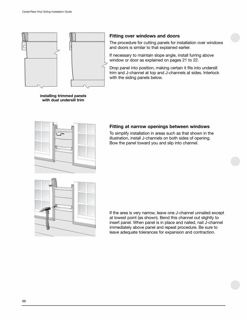
Fitting over windows and doors
The procedure for cutting panels for installation over windowsand doors is similar to that explained earlier.
If necessary to maintain slope angle, install furring abovewindow or door as explained on pages 21 to 22.
Drop panel into position, making certain it fits into undersilltrim and J-channel at top and J-channels at sides. Interlockwith the siding panels below.
Fitting at narrow openings between windows
To simplify installation in areas such as that shown in theillustration, install J-channels on both sides of opening. Bow the panel toward you and slip into channel.
If the area is very narrow, leave one J-channel unnailed exceptat lowest point (as shown). Bend this channel out slightly toinsert panel. When panel is in place and nailed, nail J-channelimmediately above panel and repeat procedure. Be sure toleave adequate tolerances for expansion and contraction.
66
CertainTeed Vinyl Siding Installation Guide
installing trimmed panels with dual undersill trim

Fitting at gable ends
Make a pattern duplicating gable slope. Use this pattern toguide cutting of panels to fit gable ends.
To make pattern:
Lock short piece of siding into panel gable starter course asshown in illustration.
Hold second piece of siding against J-channel at slope. Run pencil along edge of this piece, transferring slope angle to first piece of siding.
Cut along line using power saw or tin snips. Use resultingpattern to mark siding panels before cutting.
NOTE: Double-check angle on pattern at every course. If necessary, cut new pattern.
To install cut panels:
Slip angled end of panel into J-channel along gable edge.Leave space for expansion.
Interlock with siding panel below.
If necessary to securely fasten the last panel at gable peak,face nail as shown in illustration. This is the only place you will face nail. Use 1-1/4" to 1-1/2" aluminum nail with painted head.
NOTE: Do not cover louvers in gables.
CertainTeed Vinyl Siding Installation Guide
67
colored aluminum finish nail

Fitting under soffit
When you reach the last course of siding, you will probablyhave to rip cut panels lengthwise to fit under soffit.
NOTE: If necessary to ensure proper panel slope angle,make certain to furr out this area.
To cut and install this last course:
Install J-channel and undersill trim or dual undersill.
Measure from soffit to base of upper lock on previous courseof panels. Subtract 1/4". Mark this dimension on the panel tobe cut, taking measurement from bottom edge of panel. For amore precise cut, repeat this procedure at several other pointsalong the span to be covered by the panel.
Using a square or straightedge, draw a pencil line connectingthese points. Then score along line with utility knife. Bendpanel back and forth until it snaps.
Use snap lock punch to create tabs on outside face of panel,1/4" below cut edge. Space tabs every 6".
To install, lock bottom of cut panel into panel below. Push topedge into J-channel or undersill trim. Tabs will catch in trimand hold panel firmly in place.
NOTE: Since you will not nail this last course, it isimportant that the tabs fit properly in the trim to providesupport while allowing movement for expansion.
Finishing the top courseTo finish the top course of siding, attach cornice receiver tothe top of the wall under the eave or soffit. Trim the top panelto within 1/4" of the cornice receiver. Using a nail slot punch,punch nail slots 1/4" from the trimmed edge of the sidingpanel, 16" apart. Nail off the top course, and snap the cornicemolding into the cornice receiver. An alternate method is touse J-channel and furring strips.
68
CertainTeed Vinyl Siding Installation Guide
distance minus 1/4"
cornicemolding
cornice receiver
1/4"
1/4"

Completion
Attaching objects to siding
All external products (downspouts, shutters, and lights, for example) are attached to walls after you’ve applied thevinyl siding.
NOTE: All external fixtures must be attached to a solidbacking (such as 3/4" exterior grade plywood) to provide a secure mounting surface. Never attach a fixture directlyto vinyl siding.
When installing external products, you must allow forexpansion and contraction of siding.
You can allow for this movement in two ways:
The most convenient way to attach light fixtures is with lightblocks. Because they contain receiving channels to holdsiding panels, light blocks provide a simple way to allow forexpansion.
When attaching other fixtures, drill holes in the siding 1/4"larger than the diameter of screws, bolts, or nails being usedto fasten objects. This provides adequate clearance so sidingcan move freely underneath attached objects. Whenattaching objects, do not fasten tightly. It is also recommend-ed that you apply caulk around the screws.
Fitting at light blocksWhen cutting panels to fit at a light block, be sure to allow for expansion.
CertainTeed Vinyl Siding Installation Guide
69
1/4" to 3/8"
light blockmounting bracket

Shutter Installation
The ideal application (shown at the top) has a joint betweenthe two shutters where the shutters are secured to the home.In this way, the siding panel is not “hard nailed” between thetwo shutters and the siding is allowed free movement.
When there is no joint between shutters where the shutters aresecured to the home (as shown on the bottom), the shutter’sfasteners do not allow the siding panel to move. The sidingpanel then fails to perform because it cannot expand orcontract with the temperature changes.
Enlarge the hole in the siding for securing the shutter—thehole should be 1/4" larger than the shank of the fastener. If possible, stagger the screws securing the shutter so thatthey do not line up on the same panel. It is also a good idea to apply caulk around the screws.
70
CertainTeed Vinyl Siding Installation Guide

Preparing Wall Surfaces
For the most part, the wall preparation instructions given forhorizontal siding also apply to vertical applications. The keyrequirement, of course, is that you start with a smooth, leveland rigid substrate (plywood, wood composite, rigid foam orfiber sheathing).
NOTE: Never install vinyl siding over open furring strips orstuds. Always check with your local building code official.
With vertical siding, however, you may have to complete anextra step to provide solid nailing points along the verticaledge of the siding panel. The need for this added stepdepends on the type of substrate used and the nature of theconstruction project.
With new construction or remodeling using plywood or woodcomposite, there are no additional steps. You can nail intoplywood and wood composite substrates at any point as longas you do not exceed 12" on center.
In new construction using rigid foam or fiber sheathing, youmust install solid wood nailer strips horizontally to studsbefore applying sheathing. Use 1 x 3 wood furring positioned12" on center.
When remodeling over existing wood siding, you must applyrigid foam or fiber sheathing, shimming if necessary to createa level surface.
When remodeling over brick, block, stucco or irregular wallsurfaces, apply furring strips horizontally to create a levelsurface, then apply rigid foam or fiber sheathing. See “Tips for applying wood furring” on pages 21 to 22 and “Applying over stucco” on page 22. When reviewing the illustrations for those sections, remember that furring strips must beapplied horizontally.
Marking a base line
The procedure is virtually the same as that described earlier.However, instead of snapping a chalk line 2-1/4" above thelow point, snap it 1" above the low point.
NOTE: When installing vertical siding in high wind areas,position the fasteners at the top two nail slots of the panel.
See pages 127 to 129 for installing CedarBoards InsulatedVertical siding.
71
CertainTeed Vinyl Siding Installation Guide
Section 6 – Installing Vertical Siding (Including Board & Batten)
upper edge of topmostnailing slot
1 x 3 furring
1/2" foam sheathing
center nail in slots
always positiontopmost nail intopmost full nailslot with verticalapplications
12"
12"
nail to furring

Cornerposts
Install outside and inside cornerposts using dimensions andprocedures described earlier.
NOTE: Unlike the preparation for horizontal siding, do notinstall a starter strip for vertical siding.
Top and Bottom J-channel
Snap a base line 1" above the low part of the house. Apply J-channel along the top and bottom of the walls toreceive the siding panels.
Install the bottom J-channel (illustration 1a). Overlap J-channels 3/4". To do this, cut out a 1" section of the nailing flange and face return (see illustration 2).
If you prefer to use drip flashing with the J-channel along the bottom of the wall, fabricate the lengths you’ll need from aluminum coil stock of a color to match the siding (see illustration 1b).
Install inverted J-channel along the top of the wall, under theeave. Here again, leave a 1/4" gap between J-channel andcornerposts. Overlap J-channels 3/4" to allow for expansion.When positioning the upper J-channel, be sure to allow forexpansion of the siding panel. In most cases, position the J-channel at a point equal to the length of the panel plus 5/8"(1/4" for upper expansion and 3/8" for lower expansion).
Soffit
If you’re going to install soffit, you may want to install thereceiving channels for the soffit at this point.
The illustrations show alternative approaches for installingsiding and soffit receiving channels.
72
CertainTeed Vinyl Siding Installation Guide
illustration 2
illustration illustration 1a 1b
F-channel
1"
3/4"
soffit
J-channel
verticalsiding
soffit
J-channel
verticalsiding

If a wall requires more than one course of siding, you canproceed in one of three ways:
Use two lengths of J-channel, back-to-back, at the jointbetween the two courses (illlustration a).
Use a combination of one length of J-channel and one lengthof drip cap (illustration b).
Use a double channel lineal and flashing where required.
If using J-Channel
Snap a chalk line parallel to the bottom J-channel, at a heightequal to the length of the lower panel plus an allowance forexpansion. For example, if the lower panel is 144" long andyou’re adding 1/2" for expansion (because the temperature isabove 40° F), you strike a line 144-1/2" from the bottom J-channel. Nail inverted J-channels along this line to receivepanels from below. Leave a 1/4" gap between J-channel andcornerposts. Overlap J-channels 3/4".
Prepare for the second course by applying head flashingabove the just-installed J-channel. Then nail J-channel overthe flashing to receive the upper panel.
NOTE: Some installers prefer to use formed aluminumflashing in place of vinyl drip cap as the receiving channelfor the lower panel. This is also an acceptable approach.
J-channel at Gable Ends
Follow the procedure described earlier under the section“Preparation for Horizontal Siding” beginning on page 20.
If using double channel lineal: Measure the length of thelower panel, then add an allowance for expansion. Snap achalk line parallel to the bottom J-channel, at a height equal to your measurement. Position the lineal so the interior peak of the lower channel runs along the chalk line. Nail. Leave aminimum 3/8" gap between lineal and cornerposts when theambient temperature is higher than 40°F. When the ambienttemperature is below 40°F, leave a 1/2" gap.
Where required, overlap lineals 1-1/4". Whenever lineals areoverlapped, you must insert flashing into the upper channel, or provide additional means of flashing. Nail in place.
CertainTeed Vinyl Siding Installation Guide
73
verticalsiding
J-channel
flashing
J-channel
verticalsiding
double channel lineal
aluminum flashing(required if linealsare overlapped) orprovide additionalmeans of flashing
chalk line
verticalsiding
J-channel
drip cap
verticalsiding
a b

Wall Panels
Follow the instructions described earlier under the section“Preparation for Horizontal Siding” beginning on page 20.
Plan the panel layout
Correctly installed vertical siding should have a balancedappearance. This means that if you were to draw a vertical linedown the center point of a wall, you’d have an equal numberof panels to the right and left. If you had to trim panels to fit,the end-most panels would be of identical width.
To create this pleasing appearance, divide the space to becovered by a partial panel over both ends of a wall. Forexample, if a wall required 25 full panels plus 10", you wouldrip cut two 5" lengths of panel to create the end pieces.
Expansion and Contraction
In a vertical siding installation, most of the expansion isdownward. So instead of allowing equal space for expansionat both ends of a vertical panel, leave more space at the lowerend: allow for 1/3 of the total expansion at the top of a paneland 2/3 of the total expansion at the bottom.
For example, if the total expansion equals 3/4" (3/8" + 3/8"),allow 1/4" at the top and 1/2" at the bottom. If the totalexpansion equals 1/2" (1/4" + 1/4"), allow 3/16" at the top and 5/16" at the bottom.
NOTE: Always position top most nail at the top of the topmost full nail slot (1a). Center the remaining nails in the slots (1b). When installing siding or accessories vertically,make sure the bottom of the panel can expand downwardwithout interference.
Cut the first of the partial panels (if partial panels arenecessary). Mark the cut line by measuring from the nail hem edge. Rip cut the panel. Do not cut off the nail hem. Use a snap lock punch to create locking tabs along the cut edge. Space the tabs 6" apart.
74
CertainTeed Vinyl Siding Installation Guide
1/3
2/3
1a
1b

Before installing this partial panel into the outside cornerpost,provide additional support at the cut edge (to compensate forthe locking channel that was trimmed off).
To do this, insert furring into the channel of the outsidecornerpost and nail it to the substrate. After furring, insert alength of undersill trim into the cornerpost and nail it to thefurring. Finally, slide the cut edge of the panel into the undersilltrim, making sure to engage the snap locks (see illustration).
Using a level, make certain this panel is plumb. Nail every 12". Follow the same nailing procedures described forhorizontal siding.
Install the next panel. Lock the panel into the preceding panel,then nail every 12". Continue with succeeding panels.
When necessary, cut panels to fit around doors and windows.When marking the cut, remember to allow for expansion.
The method used to install panels around doors and windowsis determined by the need to cut a panel and the position ofthat cut.
If a cut was made next to a remaining V-groove, insert thepanel into the J-channel. If a cut removes the support providedby a V-groove, use the procedure described above to providesupport for the trimmed edge.
To finish the first course of a wall, cut the final panel to size and install it in an outside cornerpost, using the methoddescribed above.
NOTE: The cutting and supporting procedure describedabove is also used when fitting panels into insidecornerposts.
CertainTeed Vinyl Siding Installation Guide
75
cornerpost
undersilltrim
snaplocks
panel

Installing Gable End Panels
When installing vertical or Board & Batten siding on a gableend wall, you should try to create a balanced appearance.
There are two ways to do this:
You can start from the center of the wall and work toward thesides. Begin by finding the center point of the wall (beneaththe peak) and draw a plumb line. Nail two lengths of J-channel, back to back, along this line. Be sure to flashunderneath the J-channel to help prevent water damage dueto water seepage between the J-channels. Cut the upper endof the first panel to the proper height and slope. Remember toallow for expansion.
NOTE: To guide the cutting of the upper end of the panel,make a pattern duplicating the gable slope. (See page 56.)
Insert the panel into the J-channel along the gable slope. Use a level to make certain the panel is plumb. Nail every 12".Continue cutting and installing panels. Then repeat theprocedure on the remaining half of the gable end.
If you want to work from one end of the wall to the other,begin by centering a panel under the center of the peak. Mark the position of the panel on the wall, then measure the distance from the left (or right) cornerpost to mark for the left (or right) edge of the center panel.
If you need a partial panel, cut it and install at the cornerpost,following the procedure described on page 73. Cut the upper end of the panels to proper height and slope, following the procedure described above. Remember to allow for expansion.
76
CertainTeed Vinyl Siding Installation Guide
plumbline

77
CertainTeed Vinyl Siding Installation Guide
Requirements for Proper Soffit Ventilation
Proper attic ventilation is important for any home. The 2003International Building Code (IBC) Section 1203 Ventilationfurnishes a basic guide for determining proper ventilation for any home. The information provided here may under certaincircumstances not result in enough ventilation. Therefore, thecalculation provided should be used as a guide only.
The IBC guideline requires that any attic or space between the topfloor, ceiling and roof must be ventilated. It requires one squarefoot of ventilation area for every 150 square feet of attic space.
If a vapor retarder of less than one perm has been installed onthe warm side of the ceiling or if at least 50% of the requiredventilating area has already been provided by gable and ventsor ridge vents, you need add only one-half of the ventilationarea that would otherwise be required. The requirement wouldthen be one square foot of ventilation area for every 300 sq. ft.of attic space.
How to Determine Soffit Ventilation
1. Determine the local code requirement for total atticventilation.
1:150 requires 1 sq. ft. of ventilation for every 150 sq. ft. of attic space.
1:300 requires 1 sq. ft. of ventilation for every 300 sq. ft. of attic space, if a vapor barrier having a transmission rate not exceeding 1 perm is installed on the warm side of the ceiling.
2. Determine the total area of the attic (sq. ft.) to beventilated.
40 ft. x 30 ft. = 1,200 sq. ft.
3. Total free area of ventilation required for the attic.
1,200 sq. ft. / 150 = 8.0 sq. ft.
4. Convert square feet into square inches (sq. in.).
8.0 sq. ft. x 144 = 1,152 sq. in.
5. Location of vents.
50% at ridge, roof vent or gable vent = 1,152 x .50 = 576 sq. in.
50% at soffit / eave = 1,152 x .50 = 576 sq. in.
6. Total soffit ventilation area required.
Area of the soffit available for ventilation: 80 lineal ft. x 2 ft. soffit depth = 160 sq. ft.Ventilation area required per sq. ft. of soffit = 576 sq. in. /160 sq. ft. = 3.6 sq. in /sq. ft.
7. Soffit product selection.
Compare the soffit ventilation area required to themanufacturer’s soffit product literature.
Section 7 — Porch Ceilings, Soffit, Fascia
40'-0"2'-0"
2'-0"
30'-0"
eaveridge

Beaded T2 Fasten every 8" to 12"
Ironmax Fasten every 16" to 24"(as allowed by local building code)
T3-1/3" Fasten every 16" to 24"(as allowed by local building code
All other CertainTeedsoffit panels
Fasten every 16" to 24"
CertainTeed Vinyl Siding Installation Guide
78
Porch Ceilings
The procedures used to install a porch ceiling are in manyways similar to those used to install soffit. These proceduresvary slightly, depending on whether you’re working on newconstruction or a remodeling project.
New Construction Projects
Begin by installing receiving channels on all four sides of theporch. If you are using F-channel, nail it to existing walls. If youare using J-channels, you will have to install a nailing base.
If you plan to use light blocks to attach external light fixtures,install them to adequate backing.
Plan the layout of the ceiling panels to achieve an evenbalance or to align with adjacent work. If the ceiling panels will run parallel to the ceiling joists, you will have to installadditional 1 x 3 wood furring nailing strips. Install these nailingstrips perpendicular to the ceiling joists, nailing according tothe schedule below.
Invert J-channels and nail them to the underside of the woodstrips along the perimeter of the ceiling area.
Install the first panel into the channels at one end of the porch.Be sure to leave room for expansion. Nail according to theschedule below, positioning the nails in the centers of slots.Do not nail tightly. Install remaining panels. When cutting thelast panel of the first course, be sure to allow room forexpansion.
Nailing Schedule for Soffit
For areas where more than one panel length is needed, use adouble channel lineal.
If necessary, rip cut the final panel and use a snap lock punchto create tabs every 8" to 10" along the cut edge. Attach utilitytrim and insert panel into the receiving channel.
NOTE: For best results, ensure you have adequate ventilation.

79
CertainTeed Vinyl Siding Installation Guide
Remodeling Projects
Check to be sure the existing ceiling can serve as a solidnailing base. If the existing ceiling is solid, remove all existingmoldings and fixtures from the ceiling and begin by nailinginverted J-channels along the perimeter of the ceiling area.
If you plan to use light blocks to attach external light fixtures,install them to adequate backing.
Plan the layout of the ceiling panels to achieve an evenbalance or to align with adjacent work.
Use the existing ceiling as a nailing base for the panels. Installthe first panel into the channels at one end of the porch. Besure to leave room for expansion. Follow the nailing scheduleon the previous page, positioning the nails in the centers ofthe slots. Do not nail tightly. Install the remaining panels. Whencutting the last panel of the first course, be sure to allow roomfor expansion.
For areas where more than one panel length is needed, use adouble channel lineal.
If necessary, rip cut the final panel and use a snap lock punchto create tabs every 8" to 10" along the cut edge. Attach utilitytrim and insert the panel into the receiving channel.
If the existing ceiling is not solid, install nailing strips to providea secure nailing base. Then install J-channels. You will have toinstall additional nailing strips if your ceiling panels are to runparallel to the ceiling joists.
If the ceiling panels will run parallel to the ceiling joists, you willhave to install additional 1 x 3 wood furring nailing strips.Install these nailing strips perpendicular to the ceiling joists,placing a strip every 12" to 16".
Invert J-channels and nail them to the underside of woodstrips along the perimeter of the ceiling area.
Install the panels as explained above.

Soffit
You can use solid vinyl panels or perforated vinyl panels forsoffit installations. Perforated panels provide ventilation, whichhelps to reduce heat buildup in the summer and ice dams inthe winter. In buildings with roof ridge vents, you should installventilated soffit. Check local building codes to determine theamount of ventilation required. In high windload areas, youshould also check local building codes to determine if theapplication methods that are required differ from thosedescribed below.
The procedure used to install soffit depends on theconstruction of the eaves:
• Open eaves—eaves with exposed rafters or trusses—aretypical of new construction. You will also have to use openeave installation procedures if you have to removedamaged soffit at a remodeling project.
• Enclosed eaves—eaves with soffit in place—are typical of remodeling projects.
Installation over Open Eaves
The first step in installing soffit is to install the proper receivingchannels. You have several options for receiving channels. Youcan use accessories such as F-channel or J-channel, or youcan make channels using coil stock. The best approach is toselect a method that works most effectively with theconstruction techniques used to create the eave. Examinefigures 1 to4 and find the one that most closely resembles theconstruction methods used on your particular project.
If no F-channel is available, J-channel can be modified tocreate F-channel. Simply cut slots in the nail flange area whereit would be nailed to the wall. After cutting the nail flange,bend the flange back and nail to the wall. When installingBeaded T2" panels, use 3/8" H-bar or 3/8" J-channel.
Installing Receiving Channels
Install the receiving channels following the details shown infigures 1 to 4. Nail the channels every 16", positioning the nailin the center of the slot. Do not nail tightly.
If the eave span is greater than 16", you will have to installnailing strips (as shown in figure 4) and install the receivingchannels on the nailing strips.
If the soffit will turn a corner, cut and install the channel so thereis 1/4" for expansion at each of the adjoining walls.
80
CertainTeed Vinyl Siding Installation Guide
fascia cap orcoil stock
fascia cap orcoil stock
open truss
F-channel
soffit
16" to 24"*
open truss
F-channel
J-channel
soffit
16" to 24"*
open rafter
F-channel
J-channel
soffit
soffit
add nailingstrips
addframing
16" to 24"*
16" to 24"*
FIgURE 2
FIgURE 1
FIgURE 4
FIgURE 3
* To determine the maximum permissible span,consult individual product specifications andlocal building codes.

NOTE: If you don’t have the proper receiver for the soffit,you can modify J-channel to create an F-receiver. Simplycut slots in the nail flange area where the receiver will benailed to the wall, bend back the flange, and nail theflange to the wall.
Installing Soffit
Measure from the wall to the fascia board. Then subtract 1/2"to allow for expansion. Mark this dimension on a soffit paneland cross cut the panel using a power circular saw with areversed fine-tooth blade. Cut one or two panels at a time,carefully advancing the saw through the vinyl.
Insert the panel into the channel on the wall, then into thechannel at the fascia board. You may have to flex the panelslightly to insert it into the second channel. Make certain thepanel is perpendicular to the wall, then nail. Depending on theinstallation method you’re using, you’ll nail either to a nailingstrip or to the fascia board.
Nailing Schedule for Soffit
If you’re nailing to the fascia board, use small-headed nails. Drive the nail through the nail flange and “V” groove. This is one of the rare instances when face nailing ispermissible. Once a soffit panel is face-nailed, it will expand only in one direction—in this case, toward thereceiving channel. Be sure to leave space for the fullexpansion allowance in the receiving channel.
If you’re using a nailing strip, do not nail tightly—allowmovement for expansion.
Continue installing the panels by locking and nailing the soffitin place. Make certain soffit panels are fully locked along theirentire length.
CertainTeed Vinyl Siding Installation Guide
81
fascia
soffitpanels
fascia cap orcoil stock
nail into slot
nail into “v”
Beaded T2 Fasten every 8" to 12"
Ironmax Fasten every 16" to 24"(as allowed by local building code)
T3-1/3" Fasten every 16" to 24"(as allowed by local building code
All other CertainTeedsoffit panels
Fasten every 16" to 24"

Turning a Corner
To turn a corner, measure from the channel at the wall cornerto the channel at the corner of the fascia board. Subtract 1/4"for expansion. If necessary, install nailing strips to providebacking for the lineal. Cut and install soffit double channellineal or H-bar. Miter the corner soffit panels and install asdescribed above.
Completing the Installation
To complete the installation, apply utility trim and fastenaluminum fascia cap or formed aluminum coil stock withpainted trim nails. If you must face nail fascia, drill holes forthe trim nails to allow for expansion and to reduce denting of the aluminum.
Installation over Enclosed Eaves
If the existing soffit is rotted or damaged, it’s best to remove it completely before installing vinyl soffit. Then use theinstructions for open eaves.
If you’re installing perforated soffit panels and the existingsoffit doesn’t have openings for ventilation, cut an adequatenumber of openings. Then complete the installation asdescribed for open eaves.
The procedure used to install soffit over an enclosed eave is almost identical to that used for an open eave. The majordifference is the installation of the J-channel. Determine the method you’ll use to install soffit at the fascia board (see figures 5 and 6). When installing J-channel at either thewall or the fascia board, nail the J-Channel every 12" to 16".
Turning a Corner
If the soffit is to turn a corner, cut and install J-channel sothere is 1/4" for expansion at each of the adjoining walls andadjoining fascia boards. Miter the corner soffit panels andinstall as described above.
82
CertainTeed Vinyl Siding Installation Guide
fascia cap orcoil stock
nailingstrip
J-channelsoffit
enclosedeave
J-channel
soffitenclosedeave
soffit H-bar
fascia
miter soffit panels
FIgURE 5
FIgURE 6

Triple 3-1/3" Solid and InvisiVent Soffit
Installation over open eaves
In most situations, T3-1/3" Solid and InvisiVent Soffit should beinstalled like our standard soffit products. However, when it isinstalled over open eaves, follow these installation techniques.
Install receiving channels
There are two ways to install receiving channels for soffit. Thebest approach is to select a method that works most effectivelywith the construction techniques used to create the eave.Examine the illustrations, and find the one that most closelyresembles the construction methods on your particular project.
Use either 3/4" J-channel or 3/4" F-channel, or make receivingchannels using coil stock.
Install the receiving channels following the details shown in the illustrations.
Nail the channels every 12" to 16", positioning the nail in thecenter of the slot. Do not nail tightly.
NOTE: If you are concerned about excessive insectinfiltration with the InvisiVent Soffit, cover the openingwith corrosion-resistant mesh or other screening beforeinstalling the soffit.
Install soffit
Nail the soffit every 16" or 24", depending upon local buildingcodes and stud spacing. T3-1/3" soffit will span up to 24"without additional nailing strips.
Installation over existing soffit
When installing InvisiVent Soffit over an existing solid woodsoffit, you must cut openings into the existing soffit to provideadequate airflow through the soffit. The goal is to have at least9 square inches of net free air per lineal foot of soffit.Removing a center portion of the existing soffit will provide thedesired airflow.
Using a saw, cut along the length of the existing soffit. Leave2" to 3" from both the wall and the fascia so that you will haveenough wood surface to securely fasten the soffit.
Remove the center portion of the existing soffit.
Install the soffit as described above.
CertainTeed Vinyl Siding Installation Guide
83
fascia cap orcoil stock open
rafter
F-channel
soffit
add framing
J-channel
soffit

Vinyl Fascia
The wooden fascia board that encloses the front of an eavealso needs protection from the weather. To provide thisprotection, you can install vinyl or aluminum fascia panels.
There are two procedures for installing vinyl fascia panels—one for installations that include soffit, one for installationswithout soffit.
Installations without soffit
Nail undersill trim in place along the top of the fascia board.
Before installing the panel, create tabs along the top edgeusing a snap lock punch.
Hook the bottom of the fascia panel under the bottom of thefascia board. Push the top edge into the undersill trim, asshown, or behind drip edge.
Secure the panel to the bottom of the fascia board with whitetrim nails. Fasten at nail slot openings only (see illustration).Do not face nail fascia panel.
When overlapping fascia panels, first cut a notch in theunderlying panel. The notch should be 1/8" deep by 1-1/2" long. Slip the notched panel into the adjacent panel (see illustration).
To turn a corner, you must first fabricate a corner piece. Cut a length of fascia panel so it extends 6" beyond thecorner. Mark a vertical line to indicate the position of thecorner. Then cut a 90° V-notch centered on the vertical line.Score it along the vertical line and fold. Finally, create tabsalong the upper edge with a snap lock punch. The tabs mustbe raised on the outside face of the panel (shown on the next page).
Fit the panel on the corner, making sure to overlap thepreceding panel.
84
CertainTeed Vinyl Siding Installation Guide
undersilltrim
vinyl fasciacap fascia
board
nail in slotopening
1/8"
3/4"1-1/2"

For installations that include soffit
Nail the undersill trim in place along the top of the fasciaboard. Then nail F-channel along the bottom outside surfaceof the fascia board (shown).
The fascia panel will have to be rip cut to fit over the fasciaboard and F-channel. To determine the width of the panel,measure from the slot in the undersill trim to the bottom of the F-channel. Deduct 1/4" and cut (shown).
Use a snap lock punch to create tabs 1/8" below cut edge.Punch tabs every 6", with the tabs raised on the outside faceof the panel.
Install the panel by hooking the bottom of the fascia panelunder the F-channel and pushing the top into the undersill trim (shown).
Continue to install the fascia as described on the previous page.
Aluminum fascia
The techniques used to install aluminum fascia panels aresimilar to those used with vinyl—with three exceptions. There is no special undersill trim to use with aluminum fascia. Aluminum fascia is made without nail slots, so youhave to pay attention to proper nailing techniques. Andcorners are handled differently.
Install drip edge, gutter, or all-purpose trim along the top ofthe fascia board to receive the top edge of the fascia panel.
Slip the fascia panel in place. Then nail the underside of thepanel. Nail every 24", keeping the nails lined up with the soffit V-grooves.
For best appearance, first drill a slightly oversized hole. Nail the fascia with painted trim nails, using a light touch.
At the outside corners, bend a 1" flange at a 90° angle so it turns the corner. Then cut the overlapping fascia at a 45°angle. Position the panels and nail.
NOTE: If you need a piece of nonstandard size fascia, use a portable brake to form it from aluminum trim sheet.Install and nail using the same techniques you used withstandard fascia panels.
CertainTeed Vinyl Siding Installation Guide
85
6"
undersill trim
fasciaboard
F-channel
measureminus 1/4"
1/8"
6"
snap lockpunch

86
CertainTeed Vinyl Siding Installation Guide
Cedar Impressions Singles and Shakes
Important
These products are not designed for roof application. They aredesigned solely for installation on vertical surfaces.
The panels must be installed with nails over a solid substratewith nail holding strength such as plywood, oriented strandboard, or existing wood siding (minimum 7/16" thick). Theseproducts cannot be installed with staples.
NOTE: Each panel must be nailed through the round holein the center of the nail hem to control the direction ofnormal expansion and contraction. If you are installing apartial panel and the center nail hole has been cut off, drilla nail hole in the center of the nail hem of the cut paneland nail through it.
When cutting Cedar Impressions siding, use a 40-tip carbideblade mounted in the standard (not backwards) position.Using this technique will reduce burring; it does not gum upthe saw; and the blade stays sharp longer.
Drainage Channels
Some building codes require that Cedar Impressions panelsbe installed so that there is drainage space behind the panel.This space will allow moisture to escape from the panels whilepreventing water intrusion from the exterior. Information aboutinstalling drainage channels is available atwww.certainteed.com
Panel Spacing at Different Temperatures
As with any plastic siding, Cedar Impressions® D7" Perfection Shingles, T5" Straight Edge Perfection Shingles,D9" Staggered Rough-Split Shakes, and D7" Straight-Edge Rough Split Shakes expand and contract with changes intemperature. For this reason, it is important that you space the panels according to the panel temperature at the time ofinstallation. Failure to provide the proper spacing according tothese temperature ranges may result in gaps that are too largeor too small, thereby creating the potential for side lockingtabs disengaging, panels distorting, or buckling. Spacing ofpanels previously installed at a different temperature does notrequire adjustment.
Section 8 — Installing Specific CertainTeed Products

NOTE: If two temperature cells on the PanelThermometershow a color change, use the brighter color as the indicator.
Each panel has a patented PanelThermometer™ that displayspanel temperature and indicator lines that serve as guides forproper spacing between the panels. The PanelThermometer islocated on the upper right-hand corner of the panel; theindicator lines are on the upper left-hand corner.
Note that the panel temperature may change throughout theday. Space the panels according to the panel temperature atthe time of installation.
The cells on the PanelThermometer will change color toindicate the temperature of the panel.
If the brightest cell is between the numbered temperaturecells, position the panel between the correspondingtemperature indicator lines. Example: If the Panel-Thermometer reads 65, align the second panel to the 65temperature indicator line on the first panel. If the cell betweenthe 65 and 100 is brighter, position the panel between the 65and 100 temperature indicator lines.
D7" Straight Edge Perfection Shingles
First course
Strike a level line around the house and install Metal Starter. If you plan to use Cedar Impressions Mitered Cornerpost,make sure the starter strip is installed to the edge of thecorner. An alternative method of starting Cedar Impressions is to use J-channel in place of starter strip to receive thebottom edge of the panel.
Cut the end of the top course of the panel at indicator “A,”which is located above the nail slots.
CertainTeed Vinyl Siding Installation Guide
87
“A”
paneltemperatureindicatorlines
PanelThermometerReading
TemperatureIndicator Lines
0 Set to 0 line
30 Set to 30 line
65 Set to 65 line
100 Set to 100 line
130 Set to 130 line
160 Butt panels tight

window
cedar impressionsundersill trim
cedar impressionsfamily panel
88
CertainTeed Vinyl Siding Installation Guide
Starting on the right side of the wall, hook the bottom lockingleg of the panel into the starter strip and slide the panel intothe cornerpost or receiving channel. Leave 1/4" spacebetween the panel and the corner for expansion. If you areplanning to install the Mitered Cornerpost, space the panel 3"from the corner.
Fasten the panel to the wall by first nailing through the round center hole in the nailing hem at the top of the panel. Continue nailing the panel with 5 nails: one in the right-end nail slot and one at each of the QuickReference™ Nail MarkIndicators. Leave 1/8" to 1/16" between the nail heads and thepanel to allow freedom of movement during normal expansionand contraction.
Install the next panel by positioning it below the starter stripand next to the first panel. Push in and up to lock the panelinto the starter strip and the side tabs of the first panel. Spacethe second panel according to the panel temperature at thecorresponding temperature indicator lines.
Nail the panel into position starting with the round center holeand then placing the next nail in the right-end nail slot (whichoverlaps the previous panel’s left-end slot) so that the nailgoes through both panels’ nail slots simultaneously. Continuenailing the rest of the panel as described earlier.
Continue to install the remaining panels of the first course asdescribed earlier.
Second course
Cut off the right side of the D7 shingle at indicator “B,” whichis located above the nail slots. Cut straight through the panel.Drill a 3/16" hole in the center of the nail hem and nail the sidingthrough this hole to control the direction of expansion andcontraction. Another option is to nail each end of a nail slotlocated at the center of the panel.
Set the spacing using the PanelThermometer and temperatureindicator lines and install the remaining panels.
Continue to stagger the panel courses, alternating each timeto ensure a random shingle pattern up the wall.
Installing under a window or opening
Install Cedar Impressions undersill trim. Cut the panel to fitunder the window. Drill a 3/16" hole in the center of the nailhem. Using a snap lock punch, raise tab faces on the outsideof the panel 1/4" from the trimmed edge, 6" apart. Lock thepanel into the previous course, and center nail the sidingthrough the 3/16" hole drilled earlier. (Center nailing controls the direction of the panel’s expansion and contraction.) Lock the panel into place.
drill 3/16" dia. hole at midpoint of remaining panel
“B”
1/4"
QuickReference Nail Mark Indicators
1/4"

Installing over a window or opening
Cut the panel to fit over the window by measuring from thelocking tab of the previous row to the bottom of the receivingpocket. Add 1/8" to this measurement. Turn the panel overand, using this measurement, measure from the bottom of the return leg. Cut the panel to this dimension.
Install the cut panel by positioning the panel over the windowand into the receiving pocket. Lock the cut panel into theprevious course by pushing in and up. The cut edge should be 1/4" below the top of the receiving pocket.
Finishing the top course
See instructions on page 55.
Installing Cedar Impressions Mitered Cornerpost
If you are planning to install Mitered Cornerposts, space thesiding panel 3" from the edge of the corner. Lock the firstcorner over the siding, making sure it also locks into thestarter strip. Nail the corner through the top two nail slots.
T5" Straight Edge Perfection Shingles
Panel Spacing at Different Temperatures
See pages 86 to 87.
First course
Strike a level line around the house and install Metal StarterStrip. If you plan to use Cedar Impressions MiteredCornerposts, make sure the starter strip is installed to theedge of the corner. An alternative method of starting CedarImpressions is to use J-channel in place of starter strip toreceive the bottom edge of the panel.
Create a straight edge on the right side of the panel by cuttingthe top two shingles so they are flush with the bottom shingle.
Cut the end of the top course of the panel at indicator “A,”which is located above the nail slots.
Starting on the right side of the wall, hook the bottom lockingleg of the panel into the starter strip and slide the panel intothe cornerpost or receiving channel. Leave 1/4" spacebetween the panel and the corner for expansion. If you areplanning to install the Mitered Cornerpost, space the panel 3" from the corner..
CertainTeed Vinyl Siding Installation Guide
89
back side of panel to be cut
bottom ofreturn leg
bottom of receivingchannel
measure fromthe locking tabto the bottomof the receivingchannel andadd 1/8"
bottom oflocking tab
Cut off the top shingleand cut through to forma straight edge
1/4"
“A”

1/4"
drill 3/16" diameterhole at midpoint ofremaining panel
“B”
QuickReference Nail Mark Indicators
CertainTeed Vinyl Siding Installation Guide
90
Fasten the panel to the wall by first nailing through the round center hole in the nailing hem at the top of the panel. Continue nailing the panel with 5 nails: one in the right-end nail slot and one at each of the QuickReference™
Nail Mark Indicators. Leave 1/8" to 1/16" between the nailheads and the panel to allow freedom of movement duringnormal expansion and contraction.
Install the next panel by positioning it below the starter stripand next to the first panel. Push in and up to lock the panelinto the starter strip and the side tabs of the first panel. Space the second panel according to the panel temperature at the corresponding temperature indicator lines.
Nail the panel into position starting with the round center holeand then placing the next nail in the right-end nail slot (whichoverlaps the previous panel’s left-end slot) so that the nailgoes through both panels’ nail slots simultaneously. Continue nailing the rest of the panel as described above.
Continue to install the remaining panels of the first course as described.
Second course
Cut off the right side of the T5 shingle at indicator “B,” whichis located above the nail slots, cutting straight through thepanel. Drill a 3/16" hole in the center of the nail hem and nail the siding through this hole to control the direction ofexpansion and contraction. Another option is to nail each end of a nail slot located at the center of the panel.
Set the spacing using the PanelThermometer and temperatureindicator lines and install as described.
Continue to stagger panel courses, alternating each time toensure a random shingle pattern up the wall.
Installing Cedar Impressions Mitered Cornerposts
If you are planning to install Mitered Cornerposts, space thesiding panel 3" from the edge of the corner. Lock the firstcorner over the siding, making sure it also locks into thestarter strip. Nail the corner through the top two nail slots.
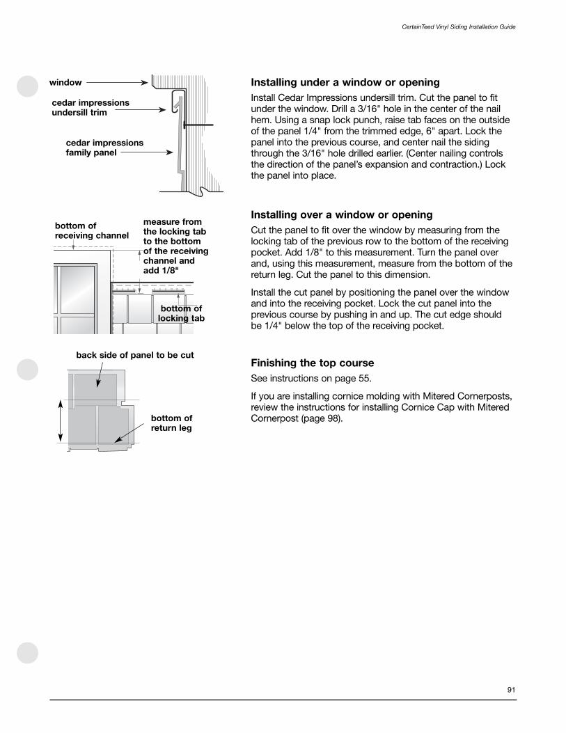
window
cedar impressionsundersill trim
cedar impressionsfamily panel
back side of panel to be cut
bottom ofreturn leg
bottom of receiving channel
measure fromthe locking tabto the bottomof the receivingchannel andadd 1/8"
bottom oflocking tab
91
CertainTeed Vinyl Siding Installation Guide
Installing under a window or opening
Install Cedar Impressions undersill trim. Cut the panel to fitunder the window. Drill a 3/16" hole in the center of the nailhem. Using a snap lock punch, raise tab faces on the outsideof the panel 1/4" from the trimmed edge, 6" apart. Lock thepanel into the previous course, and center nail the sidingthrough the 3/16" hole drilled earlier. (Center nailing controlsthe direction of the panel’s expansion and contraction.) Lockthe panel into place.
Installing over a window or opening
Cut the panel to fit over the window by measuring from thelocking tab of the previous row to the bottom of the receivingpocket. Add 1/8" to this measurement. Turn the panel overand, using this measurement, measure from the bottom of thereturn leg. Cut the panel to this dimension.
Install the cut panel by positioning the panel over the windowand into the receiving pocket. Lock the cut panel into theprevious course by pushing in and up. The cut edge should be 1/4" below the top of the receiving pocket.
Finishing the top course
See instructions on page 55.
If you are installing cornice molding with Mitered Cornerposts,review the instructions for installing Cornice Cap with MiteredCornerpost (page 98).

1/4"
QuickReference Nail Mark Indicators
1/4"
“A”
CertainTeed Vinyl Siding Installation Guide
92
D9" Staggered Rough-Split Shakes
Panel Spacing at Different Temperatures
See pages 86 and 87.
First course
Strike a level line around the house and install Metal StarterStrip. If you plan to use Mitered Cornerpost, make sure thestarter strip is installed to the edge of the corner. Analternative method of starting Cedar Impressions is to use J-channel in place of starter strip to receive the bottom edgeof the panel.
Create a straight edge on the right side of the panel by cuttingthe top shingle so it is flush with the bottom shingle. Cut endof the top course of the panel at indicator “A,” which islocated above the nail slots.
Starting on the right side of the wall, hook the bottom lockingleg of the panel into the starter strip and slide panel into thecornerpost or receiving channel. Leave 1/4" space betweenthe panel and the corner for expansion. If you are planning to install the Mitered Cornerpost, space the panel 3" from the corner.
Fasten the panel to the wall by first nailing through the roundcenter hole in the nailing hem at the top of the panel. Continuenailing the panel with 5 nails: one in the right-end nail slot and one at each of the QuickReference™ Nail Mark Indicators.Leave 1/8" to 1/16" between the nail heads and the panel to allow freedom of movement during normal expansion and contraction.
Install the next panel by positioning it below the starter stripand next to the first panel. Push in and up to lock the panelinto the starter strip and the side tabs of the first panel. Spacethe second panel according to the panel temperature at thecorresponding temperature indicator lines.
Nail the panel into position starting with the round center holeand then placing the next nail in the right-end nail slot (whichoverlaps the previous panel’s left-end slot) so that the nailgoes through both panels’ nail slots simultaneously. Continue nailing the rest of the panel.
Continue to install remaining panels of first course asdescribed earlier.

Second course
Cut off of the right side of the D9 shakes at indicator “B,”which is located above the nail slots, cutting straightthrough the panel. Drill a 3/16" hole in the center of the nailhem and nail the siding through this hole to control direction of expansion and contraction. Another option is to nail eachend of a nail slot located at the center of the panel.
Set the spacing using the PanelThermometer and temperatureindicator lines and install the panel as described earlier.
Continue to stagger panel courses, alternating each time toensure a random shingle pattern up the wall.
Installing under a window or opening
Install Cedar Impressions undersill trim. Cut the panel to fitunder the window. Drill a 3/16" hole in the center of the nailhem. Using a snap lock punch, raise tab faces on the outsideof the panel 1/4" from the trimmed edge, 6" apart. Lock thepanel into the previous course, and center nail the sidingthrough the 3/16" hole drilled earlier. (Center nailing controlsthe direction of the panel’s expansion and contraction.) Lock the panel into place.
Installing over a window or opening
Cut the panel to fit over the window by measuring from thelocking tab of the previous row to the bottom of the receivingpocket. Add 1/8" to this measurement. Turn the panel overand, using this measurement, measure from the bottom of the return leg. Cut the panel to this dimension.
Install the cut panel by positioning the panel over the windowand into the receiving pocket. Lock the cut panel into theprevious course by pushing in and up. The cut edge should be 1/4" below the top of the receiving pocket.
Finishing the top course
See instructions on page 55.
Installing Cedar Impressions Mitered Cornerpost
Install the siding on both sides of the wall before you installthe cornerpost. Space the siding 3" from the edge of thecorner. The corners are designed to fit over the panels that are used to start a new course. Lock the first corner over thesiding, making sure it also locks into the starter strip. The topof the corner must be in line with the top of the panel. Nail thecorner through the top two nail slots.
The right-side corner gap has cut marks at 1/8" increments;they allow you to fit the corner to the different panel heightsyou may encounter as you finish a course. Trim the corner gapas needed to fit the panel.
To finish the top of the cornerpost with cornice molding andcornice cap, see page 98.
CertainTeed Vinyl Siding Installation Guide
93
drill 3/16" dia. hole at midpoint of remaining panel
window
cedar impressionsundersill trim
cedar impressionsfamily panel
“B”
trim as needed to fit corner
bottom of receiving channel measure from
the locking tabto the bottomof the receivingchannel andadd 1/8"
bottom oflocking tab
back side of panel to be cut
bottom ofreturn leg

1/4"
QuickReference Nail Mark Indicators
1/4"
“A”
CertainTeed Vinyl Siding Installation Guide
94
D7" Straight Edge Rough-Split Shakes
Panel Spacing at Different Temperatures
See pages 86 and 87.
First course
Strike a level line around the house and install Metal Starter. If you plan to use Cedar Impressions Mitered Cornerpost,make sure the starter strip is installed to the edge of thecorner. An alternative method of starting Cedar Impressions is to use J-channel in place of starter strip to receive thebottom edge of the panel.
Cut the end of the top course of the panel at indicator “A,”which is located above the nail slots.
Starting on the right side of the wall, hook the bottom lockingleg of the panel into the starter strip and slide the panel intothe cornerpost or receiving channel. Leave 1/4" spacebetween the panel and the corner for expansion. If you areplanning to install the Mitered Cornerpost, space the panel 3"from the corner.
Fasten the panel to the wall by first nailing through the roundcenter hole in the nailing hem at the top of the panel. Continuenailing the panel with 5 nails: one in the right-end nail slot andone at each of the QuickReference™ Nail Mark Indicators.Leave 1/8" to 1/16" between the nail heads and the panel to allow freedom of movement during normal expansion and contraction.
Install the next panel by positioning it below the starter stripand next to the first panel. Push in and up to lock the panelinto the starter strip and the side tabs of the first panel, asshown in figure 5. Space the second panel according to the panel temperature at the corresponding temperatureindicator lines.
Nail the panel into position starting with the round center holeand then placing the next nail in the right-end nail slot (whichoverlaps the previous panel’s left-end slot) so that the nailgoes through both panels’ nail slots simultaneously. Continuenailing the rest of the panel as described above.
Continue to install remaining panels of first course asdescribed above.

Second course
Cut off the right side of the D7 shakes at indicator “B,”which is located above the nail slots, cutting straightthrough the panel. Drill a 3/16" hole in the center of the nailhem and nail the siding through this hole to control thedirection of expansion and contraction. Another option is tonail each end of a nail slot located at the center of the panel.
Set the spacing using the PanelThermometer and temperatureindicator lines and install the panel courses as described onpages 86 and 87.
Continue to stagger the panel courses, alternating each time to ensure a random shingle pattern up the wall.
Installing under a window or opening
Install Cedar Impressions undersill trim. Cut the panel to fitunder the window. Drill a 3/16" hole in the center of the nailhem. Using a snap lock punch, raise tab faces on the outsideof the panel 1/4" from the trimmed edge, 6" apart. Lock thepanel into the previous course, and center nail the sidingthrough the 3/16" hole drilled earlier. (Center nailing controls the direction of the panel’s expansion and contraction.) Lock the panel into place.
Installing over a window or opening
Cut the panel to fit over the window by measuring from thelocking tab of the previous row to the bottom of the receivingpocket. Add 1/8" to this measurement. Turn the panel overand, using this measurement, measure from the bottom of the return leg.
Cut the panel to this dimension. Install the cut panel bypositioning the panel over the window and into the receivingpocket. Lock the cut panel into the previous course bypushing in and up. The cut edge should be 1/4" below the top of the receiving pocket.
Finishing the top course
See instructions on page 55.
Installing Cedar Impressions Mitered Cornerpost
If you are planning to install Mitered Cornerposts, space thesiding panel 3" from the edge of the corner. Lock the firstcorner over the siding, making sure it also locks into thestarter strip. Nail the corner through the top two nail slots.
back side of panel to be cut
bottom ofreturn leg
window
cedar impressionsundersill trim
cedar impressionsfamily panel
bottom of receiving channel
measure fromthe locking tabto the bottomof the receivingchannel andadd 1/8"
bottom oflocking tab
drill 3/16" dia. hole at midpoint ofremaining panel
“B”
95
CertainTeed Vinyl Siding Installation Guide

drill 3/16" dia. hole at midpoint ofremaining panel
“B”
“A”
QuickReference Nail Mark Indicators
1/4"
1/4"
D7" Staggered Perfection Shingles
Panel Spacing at Different Temperatures
See pages 86 and 87.
First course
Strike a level line around the house and install Metal Starter. Ifyou plan to use Cedar Impressions Mitered Cornerpost, makesure the starter strip is installed to the edge of the corner.An alternative method of starting Cedar Impressions is to useJ-channel in place of starter strip to receive the bottom edgeof the panel.
Cut off the end of the top course of the panel at indicator “A,”which is located above the nail slots.
Starting on the right side of the wall, hook the bottom lockingleg of the panel into the starter strip and slide panel into thecornerpost or receiving channel. Leave 1/4" space betweenthe panel and the corner for expansion. If you are planning to install the Mitered Cornerpost, space the panel 3" from the corner.
Fasten the panel to the wall by first nailing through the roundcenter hole in the nailing hem at the top of the panel. Continuenailing the panel with 5 nails: one in the right-end nail slot andone at each of the QuickReference™ Nail Mark Indicators.Leave 1/8" to 1/16" between the nail heads and the panel to allow freedom of movement during normal expansion and contraction.
Install the next panel by positioning it below the starter stripand next to the first panel. Push in and up to lock the panelinto the starter strip and the side tabs of the first panel, asshown. Space the second panel according to the paneltemperature at the corresponding temperature indicator lines.
Nail the panel into position starting with the round center hole and then placing the next nail in the right-end nail slot(which overlaps the previous panel’s left-end slot) so that the nail goes through both panels’ nail slots simultaneously.Continue nailing the rest of the panel using the procedureoutlined above.
Continue to install remaining panels of first course asdescribed earlier.
Second course
Cut off the right side of the D7 shingle at indicator “B,”which is located above the nail slots, cutting straightthrough the panel. Drill a 3/16" hole in the center of the nail hemand nail siding through this hole to control direction of expansionand contraction. Another option is to nail each end of a nail slotlocated at the center of the panel.
CertainTeed Vinyl Siding Installation Guide
96

Cedar Impressions Panel
cornicemolding
cornice receiver
1/4"
1/4"
bottom of receiving channel
back side ofpanel to be cut
measure from thelocking tab to thebottom of thereceiving channeland add 1/8"
bottom oflocking tab
bottom of return leg
window
cedar impressionsundersill trim
cedar impressionsfamily panel
trim as needed to fit corner
97
CertainTeed Vinyl Siding Installation Guide
Set the spacing using the PanelThermometer and temperatureindicator lines and install as described earlier.
Continue to stagger panel courses, alternating each time toensure a random shingle pattern up the wall.
Installing under a window or opening
Install Cedar Impressions undersill trim. Cut the panel to fitunder the window. Drill a 3/16" hole in the center of the nailhem. Using a snap lock punch, raise tab faces on the outsideof the panel 1/4" from the trimmed edge, 6" apart. Lock thepanel into the previous course, and center nail the sidingthrough the 3/16" hole drilled earlier. (Center nailing controls the direction of the panel’s expansion and contraction.) Lock the panel into place.
Installing over a window or opening
Cut the panel to fit over the window by measuring from thelocking tab of the previous row to the bottom of the receivingpocket. Add 1/8" to this measurement. Turn the panel overand, using this measurement, measure from the bottom of the return leg.
Cut the panel to this dimension. Install the cut panel bypositioning the panel over the window and into the receivingpocket. Lock the cut panel into the previous course bypushing in and up. The cut edge should be 1/4" below the top of the receiving pocket.
Finishing the top course
See instructions on page 55.
Installing Cedar Impressions Mitered Cornerpost
Install the siding on both sides of the wall before you install thecornerpost. Space the siding 3" from the edge of the corner. Thecorners are designed to fit over the panels that are used to starta new course. Lock the first corner over the siding, making sureit also locks into the starter strip. The top of the corner must beinline with the top of the panel. Nail the corner through the toptwo nail slots.
The right-side corner gap has cut marks at 1/8" increments.They allow you to fit the corner to the different butt heights youmay encounter as you finish a course. Trim the corner gap asneeded to fit the panel.

CertainTeed Vinyl Siding Installation Guide
98
Cornice Cap with Cedar ImpressionsMitered Cornerpost
generalBefore applying siding and accessories, make certain thesubstrate is watertight. In order to be properly protected fromprecipitation, the substrate may need to be flashed to shedwater to the exterior. The siding and accessories alone are not meant to be a watertight barrier.
Cedar Impressions panels will be installed from the right tothe left.
NOTE: If the application situation allows, install both wall sides of the corner at the same time. This will allow for small corrections to be made to the cornerpost installation.
Cedar Impressions outside corner installation
Install the first Cedar Impressions panel 3" from the edge ofthe outside wall.
Hook the corner piece over the siding, making sure it engagesinto the starter strip and nail through the top two holes.
Continue installing corner pieces as you move up the wall.
When you reach the top panel, cut to length and nail withcolor-matched finish nails.
If you end on an outside corner that has a cornerpostinstalled, you need to measure from the edge of the panel tothe edge of the cornerpost. Add 1-1/2" to this dimension; itwill be the panel length.

cornice receiver
cornice cap
1/4" from edge
99
CertainTeed Vinyl Siding Installation Guide
Angle the panel into the cornerpost and slide to the left untilthe side tabs clear. Next, slide the panel to the right until youhave the correct temperature marks lined up.
Install the top section of Mitered Cornerpost. Leave 1/4"between the top corner piece and the cornice receiver.
NOTE: Depending upon the area of the D9 StaggeredRough-Split panel you finish with, you may have to installfurring behind the cornice receiver to accommodate thethickness of the Rough-Split panel.
Snap the cornice molding into the cornice receiver. The cornice molding should be 1/4" from the edge of the wall.
Hook the top of the cornice cap over the end of the cornice moldings and snap the bottom into place.
Alternately, you can slide the cornice cap over one of the cornice moldings until the other cornice molding can be inserted.

CertainTeed Vinyl Siding Installation Guide
100
Cedar Impressions Inside Cornerpost
Siding and accessories alone are not meant to be a watertightbarrier. Before applying siding and accessories, make certainthe substrate is watertight. Flash the substrate so that it shedswater outside the siding.
Cedar Impressions panels are installed from right to left. If the application situation allows, install both wall sides at the corner at the same time. This will allow you to make small corrections to the Inside Cornerpost installation as you move up the wall.
Installing Cedar Impressions Inside Cornerpost
When installing Inside Cornerposts, be sure to run MetalStarter to the inside corner.
Install Cedar Impressions panels from right to left. Install theCedar Impressions panels into the inside corners. Leave a 3"gap on each side of the corner.
Once the panel has been fastened, hook the Cornerpost overthe siding, making sure it is locked into the starter strip. Nailthrough the top two holes of the Cornerpost. Continueinstalling the Cornerpost as you move up the wall.
When you reach the top panel, cut the Cornerpost to lengthand nail it \with a color matched finish nail.
If the Inside Cornerpost is installed before the siding, you willhave to cut the Cedar Impressions panel to fit.
Measure from the edge of the last installed panel to the edgeof the Cornerpost. Add 1-1/4" to this dimension, and cut thepanel to length.
Angle the panel under the Cornerpost and slide it to the leftuntil the side tabs clear. Then slide the panel to the right untilthe correct temperature marks on the panel are lined up.
Fasten the panel to the wall.

101
CertainTeed Vinyl Siding Installation Guide
Cedar Impressions Bay Window Cornerposts
When installing Bay Window Cornerposts, be sure to runShingle Starter to both corners, and install Cedar Impressionspanels from right to left.
Install the Cedar Impressions panels into both the inside and outside cornerposts. Leave a 2.5" gap on each side of the corner.
Once the panel has been fastened, hook the cornerposts overthe siding, making sure they are locked into the starter strip.
Nail through the top two holes of the Cornerpost.
Continue installing the Cornerpost as you move up the wall.When you reach the top panel, cut the Cornerpost to lengthand nail it with a color matched finish nail.
If the Cornerposts are installed before the siding, you will haveto cut the Cedar Impressions panel to fit. To do this, measurefrom the edge of the last installed panel to the edge of theCornerpost. Add 1-1/4" to this dimension, and cut the panel tolength. Angle the panel under the Cornerpost and slide it tothe left until the side tabs clear. Then slide the panel to theright until the correct temperature marks on the panel are linedup. Fasten the panel to the wall.

Half-Round Shingles
Important
This product is not designed for roof application. It is designedsolely for installation on vertical surfaces.
Panels must be installed with nails over a solid substrate withnail holding strength such as plywood, oriented strand board,or existing wood siding (minimum 7⁄16" thick). This productcannot be installed with staples.
NOTE: Each panel must be nailed through the round holein the center of the nail hem to control the direction ofnormal expansion and contraction. If you are installing apartial panel and the center nail hole has been cut off, drilla nail hole in the center of the nail hem of the cut paneland nail through it.
When cutting Cedar Impressions siding, use a 40-tip carbideblade mounted in the standard (not backwards) position.Using this technique will reduce burring; it does not gum up the saw; and the blade stays sharp longer.
Panel Spacing at Different Temperatures
As with any plastic siding, Cedar Impressions expands andcontracts with changes in temperature. For this reason, it isimportant that you space the panels according to the paneltemperature at the time of installation. Failure to provide theproper spacing according to these temperature ranges mayresult in gaps that are too large or too small, thereby creatingthe potential for side lock tabs disengaging, panel distortion,or buckling. Spacing of panels previously installed at adifferent temperature does not require adjustment.
Each panel has indicator lines that serve as guides for properspacing between the panels. The indicator lines are on theupper left-hand corner. Before you install Half-Round Shingles,make sure the panels are acclimated to the ambienttemperature. As the ambient temperature changes during theday, it may be necessary to adjust the panel spacing to reflectthe change in the panel temperature.
Space the panels according to the panel temperature at thetime of installation.
30° F
65° F
100° F
paneltemperatureindicatormarks
use these marks on installed panelsfor quick alignment of secondcourse—use temperature indicatorsfor final panel adjustments
CertainTeed Vinyl Siding Installation Guide
102
Panel Temperature Temperature Indicator Lines
30° to 40° Set to 30 line
41° to 55° Set halfway between 30 and 65 lines
56° to 75° Set to 65 line
76° to 90° Set halfway between 65 and 100 lines
91° to 100° Set to 100 line

1/4"
1/4"
2-5/8"
always secure firstusing center pin hole
1/8" to 1/4"
illustration 1a illustration 1b
103
CertainTeed Vinyl Siding Installation Guide
First course
Strike a level line around the house and install Metal StarterStrip (see illustration 1a). An alternative method of starting Half-Rounds is to use J-channel in place of starter strip, to receivethe bottom edge of the panel (see illustration 1b). To use thismethod, the rounded portion of the panel must be removedbelow the locking leg to create a continuous straight edge.
NOTE: When using a J-channel as a starter, leave 1/4"between the siding panel and pocket.
Remove 2-5/8" from the left side of the upper panel course,leaving a 90° left side edge.
Starting on the left side of the wall, hook the bottom edge ofthe panel into the starter strip and slide the panel into thecornerpost or receiving channel. Leave 1/4" space betweenthe panel and the inside wall of the cornerpost for expansion.
Fasten the panel to the wall by first nailing through the roundcenter hole of the nailing hem at the top of the panel. Thenfasten the rest of the panel by nailing through the centers ofthe remaining nail slots a maximum of every 8" to 16" oncenter. Provide 1/8" to 1/16" between the nail head and thepanel to allow freedom of movement during normal expansionand contraction. Failure to provide this space between nailhead and panel will cause the panel to buckle. Do not put anail into the far right slot until overlapping panel is positionedfor installation.
Install the next panel by using a dual motion of hooking intothe starter strip and sliding over the previous panel. This willensure a proper lap.
Position overlapping panel so that there is 1/8" to 1/4"between the panels, depending on the panel temperature at time of installation. The spacing may appear larger orsmaller than the spaces between the shingles on the panel.This is normal and necessary in order to allow for expansionand contraction.
Nail in the center of the far left slot of the overlapping panel.
Continue to install the remaining panels of first course asdescribed above.

13-1/4"
side locking tabs
drill 3/16" diameter hole at midpoint of remaining panel
CertainTeed Vinyl Siding Installation Guide
104
Second course
Remove 13-1/4" of the left side measured from the upperpanel, cutting straight through the lower panel course. (Notethe small mark on the face of the panel.) Drill a 3/16" hole inthe center of the nail hem and nail the siding through this holeto control the direction of expansion and contraction.
NOTE: The 13-1/4" spacing provides the farthestseparation of overlapping courses.
For easier application of complete panels, 1/4" vertical lineshave been added to the top edge of the nail flange for quickinitial alignment. Simply align the right edge of the upper panelwith one of the vertical alignment marks on the lower course.However, always use the temperature indicator marks on theright side of the upper panels for final alignment.
Cedar Impressions Half-Rounds may also be installed bysliding the right panel up while ensuring the side lock tabsengage with the flange of the left panel. This method is usefulwhen installing panels into cornerposts and J-channel aroundwindows and doors.
Continue to stagger panel courses, alternating each time toensure a random shingle pattern up the wall.

window
cedar impressionsundersill trim
cedar impressionsfamily panel
105
CertainTeed Vinyl Siding Installation Guide
Installing under a window or opening
Install Cedar Impressions undersill trim. Cut the panel to fitunder the window. Drill a 3/16" hole in the center of the nailhem. Using a snap lock punch, raise tab faces on the outsideof the panel 1/4" from the trimmed edge, 6" apart. Lock thepanel into the previous course, and center nail the sidingthrough the 3/16" hole drilled earlier. (Center nailing controlsthe direction of the panel’s expansion and contraction.) Lockthe panel into place.
Installing over a window or opening
To install siding over a window, measure from the lock tab ofthe course below the window top to the top of the window.Add 3/4". Cut the panel to this dimension. This will allow thepanel to be lowered down far enough to engage the lockingtabs of the lower panel. After it is positioned into the lockedposition, the cut edge will still be 1/4" below the top of the J-channel.
Finishing the top course
See instructions on page 55.

gable height
5-1/2"
top of gap
5-1/2"
cut
remove
CertainTeed Vinyl Siding Installation Guide
106
Half-Round Shingles in Gable Ends
NOTE: The following instructions focus on a gableinstallation. They also are geared towards an enclosedgable, started with a J-channel. The Half-Round can alsobe started with starter strip. This is an example only!
Installing receiving channels
Frame the border area with 3/4" J-channel. Nail in placeloosely. Miter joints accordingly.
NOTE: You also can use 3-1/2" or 5" lineals to frame gableends and gable base. For instructions on cutting linealsfor peaks, see “Gable Trim” on page 57.
Cut enough J-channel to span the base of the gable, thensecure it in place.
NOTE: The instructions below show how to create a gable installation with a complete, centered Half-Round at the peak.
Making the starter course
Gable installations properly terminate with a single round atthe peak. To create this effect, you usually have to adjust theheight of the starter course.
To determine the height of the starter course, calculate thenumber of rows required to complete the gable.
Use the following formula:
Gable height (inches) ÷12.5 (face exposure) = courses required
NOTE: Gable height is measured from inside thehorizontal receiving channel to the peak (allowing 1/4" at top and bottom for expansion).
For example, with a 68" gable height, the calculations wouldbe 68 ÷ 12.5" = 5 with a remainder of 0.44. This means youwould need 5 full courses plus 0.44 x 12.5" (face exposure ofpanel) = 5.5" measured from the top edge of the gap on theupper course (illustrated). This is the visible height for yourstarter course. The visible height is the vertical dimension ofthe panel you’ll see below the first full row of rounds.
Once you’ve determined the visible height of the startercourse, mark this dimension on a Half-Round Shingle panel.Measure from the top of the gap on the upper course(illustrated). Draw a cutting line the entire length of panel.
Cut and use the top section, which contains the locks, as yourstarter course. Cut enough panels to span base of the gable.

30ºF
65ºF
100ºF
9-3/8"
9-3/8"
gap or “v”
remainder of“scallop”
5-1/2"
plumbline
plumbline
finishedheight line
107
CertainTeed Vinyl Siding Installation Guide
Hanging the starter course
To end up with a single “round” centered at the peak of thegable, you must properly locate the first starter panel.
Begin by marking a vertical plumb line from the peak.
Then measure and mark the finished height line. In ourexample, using a starter course with a 5-1/2" visible height,the finished height is 9-3/8".
With your ruler inserted into the pocket of the lower J-channel, mark a line on the substrate equal to the finishedheight (remember to allow 1/4" for expansion). Repeat atseveral points along the gable base. Use these marks to strike a horizontal level line that will guide the nailing of thestarter course.
The point where the plumb line and the horizontal level lineintersect marks the starting point for hanging the first startercourse panel (if the first starter panel intersects the plumb line).
Determine whether you will center a “scallop” or a “V” at thestarting point. This decision is based on the number ofcourses required to complete the gable.
The rule of thumb is:
Center an upper scallop if the initial calculations had less than0.5 courses remaining (0.44 in our example).
Center the gap or “V” of the upper course if more than 0.5courses remained.
(In our example we require 5.44 courses, so we would centeron a scallop.)
More than one panel will probably be required to reach theplumb line. Measure from the plumb line into the pocketreceiving channel (leaving 1/4" for expansion) as illustrated at left.

plumbline
152" 8"
24"
mark cut for roof slope
length of firstfull panel
length of firstfull panel
secondalignmentmark
line represents the bottom ofthe first full course of scallops
CertainTeed Vinyl Siding Installation Guide
108
If you require an odd number of courses (i.e. five full coursesplus starting course), subtract 8" from the distance from theplumb line to the left receiving pocket (remember to allow 1/4"for expansion).
If you require an even number of courses (i.e. 6 full coursesplus starting course), subtract 18-1/2" from the dimension.
NOTE: The 8" and 18-1/2" dimensions ensure having a fullcentered scallop at the topmost part of the gable.
For example: If the measurement required to the plumb line(minus 8" for an odd number of full courses) is 152", then152"÷ 32" = 4 full panels plus 0.75% of one panel or 24"measured from the edge of the texture on the right side(temperature indicator side).
Create a cutting guide as described earlier for gableapplications and trim first panel (for this example) at 24".Continue to hang the remaining starter course strips,remembering to center nail first.
Installing first full panel
It is important to stagger the panels, as described in thissection. The easiest way to determine the length of panelrequired is to measure from the alignment line on the nailflange of the starter panel to the edge of the roof slope (see illustration).
Using this measurement, drill a hole centered in the remainingnail flange as described earlier. Lock the first full exposurepanel to the starter course after trimming for roof slope.
After locking panel in place, center pin the panel.
Lapping remaining panels
The remaining panels to be installed must be lapped inaccordance with the current temperature.
Repeat this process for the entire course.
At the end of each course, trim panels to the gable angle. Be sure to allow for expansion at the J-channels.
Installing the last round
When you reach the peak, trim the last round to the desiredheight by removing the locks. Then face nail to the substrate,using a color-matched finishing nail.

no less than 70°
30'
drill and center nail
109
CertainTeed Vinyl Siding Installation Guide
Cedar Impressions on a Steep Rake
A solid nailable substrate is required for this product. The substrate must have the nail holding equivalent of a 3/4" penetration of a nail into solid wood.
Installing Cedar Impressions on Non-vertical Walls
Cedar Impressions must never be used as a roofing material.However, the panels can be used on non-vertical applicationsthat meet the following conditions:
• The non-vertical wall must be decorative and not functional.
• The non-vertical wall must not be greater than 20° off thevertical (no less than a 70° angle).
• The top of the wall cannot be higher than 30' above grade.Because of different wind-load requirements, your localbuilding code may stipulate a lower height. Use the lesser of the two heights.
Before you install Cedar Impressions on a non-vertical wall, install a non-binding, self-adhering underlayment orwaterproofing membrane. Cap the uppermost edge of the top course of siding to prevent water from getting behind the siding. Flash all accessories to shed water away from thesubstrate. Siding alone is not meant to be a watertight barrier.
hand punch slots 16"from center and nail
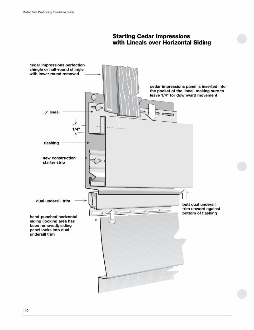
cedar impressions panel is inserted intothe pocket of the lineal, making sure toleave 1/4" for downward movement
cedar impressions perfectionshingle or half-round shingle with lower round removed
5" lineal
1/4"
flashing
new constructionstarter strip
dual undersill trim
hand-punched horizontalsiding (locking area hasbeen removed); sidingpanel locks into dualundersill trim
butt dual undersilltrim upward againstbottom of flashing
CertainTeed Vinyl Siding Installation Guide
110
Starting Cedar Impressions with Lineals over Horizontal Siding

center nail inslot of metalstarter strip
finalassembly
cut away anddiscard
hand punch slots
CertainTeed Vinyl Siding Installation Guide
Starting Cedar Impressionsover Horizontal Siding
NOTE: Half-Round Shingles are shown, but this methodalso works for the Perfection shingle.
Cut away nail flange and discard.
Hand punch nail slots in panel face and secure panel.
Secure Metal Starter Strip after hand punching and securingsiding piece.
NOTE: Only the Metal Starter Strip may be used withCedar Impressions.
Lock Cedar Impressions panels into starter strip and secure.
111

removal of nail flange up to the locking lug:requires drilling a new center hole, andpunching a slot on both ends (16" from center); this allows for expansion
removal of 1-1/8" or more of the nail flange: use cornice receiver or F-channel and cornicemolding—drill a new center hole and punch aslot on both ends (16" from center)
removal of 1-1/2" or more: use either J-channel or cornice receiver and cornicemolding—drill a new center hole, and punch aslot on both ends (16" from center)
removal of 3" or more: use standard 3/4" pocketJ-channel or cornice receiver and cornicemolding combinations—drill a new center hole,and punch a slot on both ends (16" from center)
CertainTeed Vinyl Siding Installation Guide
112
Application of Half-RoundShingle under Soffit
The amount of trimming required for a Cedar ImpressionsHalf-Round Shingle panel determines the accessory piecerequired to receive it. See the descriptions below.
Perfection Shingles do not have these restrictions.

113
CertainTeed Vinyl Siding Installation Guide
Special Effects with Cedar Impressions
Another look can be achieved by using the lower locking tabs.First, remove the protective material from the sides of the tabs(see left). Lock the upper panel into the tab and secure.
NOTE: This method can also be used to finish the topcourse of shingles.
Perfection Shingles can also be mixed within Half-RoundShingles applications as shown below left.
To do this, the “flash” material must be removed from thelower tabs on the face of the Half-Round panels with a utilityknife (as shown above). The resulting lock allows the nextcourse of Half-Rounds to be secured.
Lock Perfection Shingles into newly created lock tabs and secure.
Cedar Impressions Half-Round Shingles with Perfection Shingles.

cam clip
roof snake bar
wonderbar
snap rivet
CertainTeed Vinyl Siding Installation Guide
114
Replacing a Damaged Cedar ImpressionsPanel with the Repair Kit (Option 1)
Cam clips and snap rivets are included in the kit.
You will also need a hammer, utility knife, chisel, and “wonderbar” or “roof snake bar.”
Removing the damaged panel
Cut a large rectangle out of the damaged panel. Cut or chiselthrough the sides of the panel and remove the lower half.
Pry the nails out of the nail hem of the damaged panel.

115
CertainTeed Vinyl Siding Installation Guide
Push up on the panel to unlock it, and then pull down toremove the damaged panel.
Preparing the new panel
Cut off all top locking tabs.
Flip the panel over and cut 1/8" off the side locking tabs.
NOTE: For Half-Round Shingles, notch the side lockingtab on a 45˚ angle.
NOTE: On the D9" Staggered Rough-Split Shakes and T5"Straight Edge Perfection Shingles panels, there are 7locking tabs, but there are only 6 cam clips per kit. Placeone cam clip in the nail slot above each of the end lockingtabs, working towards the middle of the panel using all 6clips. Leave one locking tab in the middle of the panelwithout the cam clip.
NOTE: For Half-Round Shingles install four cam clips innail slot locations (left to right) 3, 13, 18, and 28.

CertainTeed Vinyl Siding Installation Guide
116
From the back, insert a snap rivet into a nail slot above one ofthe locking tabs. Then place a cam clip over the snap rivet.Push on the back button of the snap rivet to secure the clip to the panel. Repeat over each locking tab area. Now you are ready to install the new panel.
Installing the new panel
Slide the left side of the new panel into the side locking tabs.To engage the right side tabs into the existing panel, flex thepanel out from the center. As you raise the new panel intoposition, make sure the bottom lip of the panel engages thelocking tabs on the panel below.
Lift up the panel above the new panel far enough to place the nails into the old nail holes.
Using your WonderBar or roof snake bar, drive the nails in by placing the bar on the nail head and hitting the bar with a hammer.
While applying pressure to the top panel, pull down on thecam cords. Make sure each cam clip engages the lip of the panel above it. Keep pulling down on the cam cords until they break off.

locate locktab withchisel tip andremove
Cedar Impressions panel (upper course)
butt leg of upper CedarImpressions panel
Cedar Impressions panel (lower course)
117
CertainTeed Vinyl Siding Installation Guide
Replacing a Damaged Cedar ImpressionsPanel (Option 2)
You will need a hammer, wood chisel, and hacksaw or utility knife.
Use a wood chisel to remove the lock tabs on the top side of the damaged panel. Lock tabs can be located by using thechisel to slightly lift the panel locked into the upper portion ofthe damaged panel.
After locating the lock tabs, place the bevel of the chisel downagainst the face of the damaged panel; use a hammer and thechisel to knock off the lock tabs of the damaged panel. Thenremove the nails on the damaged panel, and pull the paneldown and remove it.
On the replacement panel, use a hacksaw or utility knife to cutthe lock tabs to half their original length. Slide the replacementpanel back into the position of the removed damaged panel.
Use the hammer handle to put pressure against the bottombutt of the replacement panel to force pressure upwardenough that the replacement panel will engage with the panel above.
Drill a nail hole in the center of the top portion of thereplacement panel. Then use a colored trim nail to control the direction of expansion of the replacement.
NOTE: While this method provides an aestheticallyacceptable replacement, it does not actually secure thepanel to the wall. The only way to secure a replacementpanel with nails is to remove the siding from the top of thewall down until the damaged panel can be removed.
colored trim nail
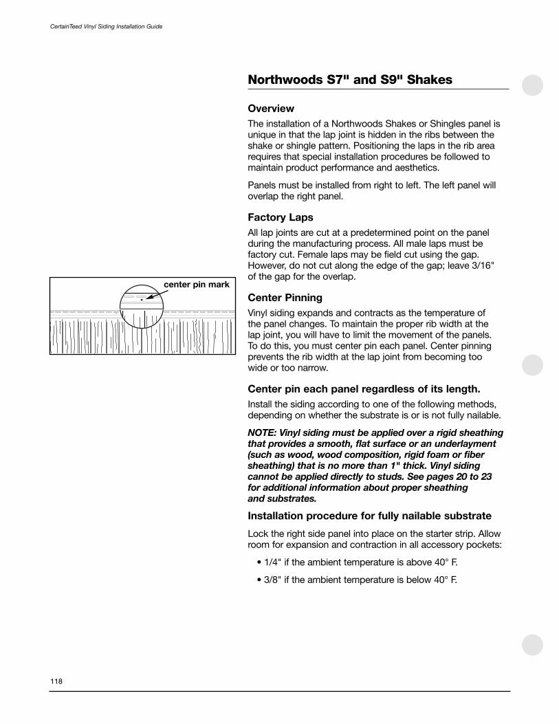
center pin mark
CertainTeed Vinyl Siding Installation Guide
118
Northwoods S7" and S9" Shakes
Overview
The installation of a Northwoods Shakes or Shingles panel isunique in that the lap joint is hidden in the ribs between theshake or shingle pattern. Positioning the laps in the rib arearequires that special installation procedures be followed tomaintain product performance and aesthetics.
Panels must be installed from right to left. The left panel willoverlap the right panel.
Factory Laps
All lap joints are cut at a predetermined point on the panelduring the manufacturing process. All male laps must befactory cut. Female laps may be field cut using the gap.However, do not cut along the edge of the gap; leave 3/16" of the gap for the overlap.
Center Pinning
Vinyl siding expands and contracts as the temperature of the panel changes. To maintain the proper rib width at the lap joint, you will have to limit the movement of the panels. To do this, you must center pin each panel. Center pinningprevents the rib width at the lap joint from becoming too wide or too narrow.
Center pin each panel regardless of its length.
Install the siding according to one of the following methods,depending on whether the substrate is or is not fully nailable.
NOTE: Vinyl siding must be applied over a rigid sheathingthat provides a smooth, flat surface or an underlayment(such as wood, wood composition, rigid foam or fibersheathing) that is no more than 1" thick. Vinyl sidingcannot be applied directly to studs. See pages 20 to 23 for additional information about proper sheathing and substrates.
Installation procedure for fully nailable substrate
Lock the right side panel into place on the starter strip. Allowroom for expansion and contraction in all accessory pockets:
• 1/4" if the ambient temperature is above 40° F.
• 3/8" if the ambient temperature is below 40° F.

temperature marks
30° 65° 100°
2' min.
119
CertainTeed Vinyl Siding Installation Guide
Locate the mark at the center of the panel. Use the nailing slotclosest to this mark. Center pin the panel in this location usingone of the following options:
a. Install a nail on both ends of the same nail slot.
b. Drill a 3/16" diameter hole through the nail hem andsubstrate, and place a single fastener through this newlydrilled hole.
Install nails in the center of the remaining slots, 16" apart.Leave adequate room between the fastener head and the nailflange for expansion and contraction (approximately 1/16" to1/8"). Do not hard nail these fasteners.
Install the next panel to the left of the installed panel. Lap thispanel over the installed panel, positioning the right edge of thepanel to the appropriate temperature mark, which is located inthe factory notch area.
If the ambient temperature is less than 45°F, lap the panel to the first (30°) mark.
If the ambient temperature is between 45°F to 80°F, lap thepanel to the second (65°) mark.
If the ambient temperature is greater than 80°F, lap the panelto the third (100°) mark.
Fasten the panel according to the procedure described earlier.
Continue the first course of siding, remembering to center pinevery panel.
Start the next course of siding from the right side, repeatingthe earlier steps. Offset the laps from course to course aminimum of 2 feet.

Installation procedure for a NON-fully nailable substrate
Lock the right side panel into place on the starter strip. Allowroom for expansion and contraction in all accessory pockets:
• 1/4" if the ambient temperature is above 40° F.
• 3/8" if the ambient temperature is below 40° F.
Locate the framing member (wall stud) nearest the center ofthe panel and center pin the panel into the framing memberusing one of the following options:
a. If a nail slot is located over the framing member, install anail on both ends of the same nail slot.
b. Drill a 3/16" diameter hole through the nail hem andframing member, and place a single fastener through thisnewly drilled hole.
Install nails in the center of the remaining slots, 16" apart,secured into a framing member. Leave enough room betweenthe fastener head and the nail flange for expansion andcontraction (approximately 1/16" to 1/8"). Do not hard nailthese fasteners.
Install the next panel to the left of the installed panel. Lap thispanel over the installed panel, positioning the right edge of thepanel to the appropriate temperature mark. Fasten the panelaccording the procedure described earlier and continue thecourse of siding.
Start the next course of siding from the right side, repeatingthe steps described earlier. Remember, offset the laps fromcourse to course a minimum of 2 feet.
cutaway view of wall construction
wallstud
non nailable substratepanelcenter
wall studclosest topanel center
CertainTeed Vinyl Siding Installation Guide
120

center pin mark
121
CertainTeed Vinyl Siding Installation Guide
Northwoods S10" Shakes
Overview
The installation of Northwoods 10" Shakes is unique in thatthe lap joint is hidden in the ribs between the shake patterns.Positioning the laps in the rib area requires that specialinstallation procedures be followed to maintain productperformance and aesthetics.
Panels must be installed from right to left. The left panel willoverlap the right panel.
Factory Laps
All lap joints are cut at a predetermined point on the panelduring the manufacturing process. All laps must be factorycut. There should be NO field cutting of laps.
Install the panels from right to left. The left panel will overlapthe right panel.
Center Pinning
Vinyl siding expands and contracts as the temperature of thepanel changes. To maintain the proper rib width at the lapjoint, you will have to limit the movement of the panels. To do this, you must center pin each panel. Center pinningprevents the rib width at the lap joint from becoming too wide or too narrow.
Center pin each panel regardless of its length.
NOTE: Vinyl siding must be applied over a rigid sheathingthat provides a smooth, flat surface or an underlayment(such as wood, wood composition, rigid foam or fibersheathing) that is no more than 1" thick. Vinyl sidingcannot be applied directly to studs. See pages 20 to 23 for additional information about proper sheathing and substrates.
Install the siding according to one of the following methods,depending on whether the substrate is or is not fully nailable.
Installation procedure for fully nailable substrate
Lock the right side panel into place on the starter strip. Allowroom for expansion and contraction in all accessory pockets:
• 1/4" if the ambient temperature is above 40° F.
• 3/8" if the ambient temperature is below 40° F.

Locate the mark indicating the center of the panel. Use thenailing slot closest to this mark. Center pin the panel in thislocation using one of the following options:
a. Install a nail on both ends of the same nail slot.
b. Drill a 3/16" diameter hole through the nail hem andsubstrate, and place a single fastener through this newlydrilled hole.
Install nails in the center of the remaining slots, 16" apart.Leave adequate room between the fastener head and thenail flange for expansion and contraction (approximately1/16" to 1/8"). Do not hard nail these fasteners.
Install the next panel to the left of the installed panel. Lapthis panel over the installed panel, positioning the right edgeof the panel to a vertical “alignment mark” located in thefactory notch area (approximately 1" from the left, top edge)of the installed panel.
Fasten the panel according to the procedure describedearlier, remembering to center pin every panel.
Continue the first course of siding.
Start the next course of siding from the right side, repeatingthe steps above. Remember, offset the laps from course tocourse a minimum of 2 feet.
Installation procedure for a NON-fully nailable substrate
Lock the right side panel into place on the starter strip.Allow room for expansion and contraction in all accessorypockets:
• 1/4" if the ambient temperature is above 40° F.
• 3/8" if the ambient temperature is below 40° F.
Locate the framing member (wall stud) nearest the center ofthe panel and center pin the panel into the framingmember using one of the following options:
a. If a nail slot is located over the framing member, install a nail on both ends of the same nail slot.
b. Drill a 3/16" diameter hole through the nail hem andframing member, and place a single fastener through this newly drilled hole.
2' min.
cutaway view of wall construction
wallstud
non-nailable substrate
panelcenter
wall studclosest topanel center
alignment mark
CertainTeed Vinyl Siding Installation Guide
122

123
CertainTeed Vinyl Siding Installation Guide
Install nails in the center of the remaining slots, 16" apart,secured into a framing member. Leave enough room betweenthe fastener head and the nail flange for expansion andcontraction (approximately 1/16" to 1/8"). Do not hard nailthese fasteners.
Install the next panel to the left of the installed panel. Lap thispanel over the installed panel, positioning the right edge of thepanel to the vertical “alignment mark” located in the factorynotch area (approximately 1" from the left, top edge) of theinstalled panel.
Fasten the panel according the procedure described earlierand continue the course of siding.
Start the next course of siding from the right side, repeatingthe steps described earlier. Remember, offset the laps fromcourse to course a minimum of 2 feet.

Installing CedarBoards Siding
CedarBoards™ Insulated Siding will help even out wallsurfaces. However, to minimize extremes in the peaks andvalleys of uneven walls, you may have to repair theunderlayment. Make sure the substrate is smooth, flat, andweathertight. If the surface is significantly uneven, apply 1/4"(minimum) foam sheathing before installing CedarBoardsSiding. If the wall surface is smooth, use standardunderlayment practices.
Horizontal Siding
The key to creating a visually attractive installation is to lapaway from areas where people normally walk or gather. For example, on the front wall, work from the corners to the entrance door (so overlaps face away from door). On side walls, work from the rear corners toward the front.This approach minimizes the effect of lapping and producesthe best appearance. Keep lap appearance in mindthroughout installation.
Starter strips
Insulated siding is thicker than hollow vinyl siding. To accom-modate the 1-1/4" thickness, we recommend that you use theCedarBoards starter strip.
An alternative method of starting CedarBoards is to use 1-1/4"J-Channel in place of starter strip to receive the bottom edgeof the panel.
Fastening
Use 2" (minimum) corrosion-resistant nails to penetrate thewood substrate at least 3/4". Drive the nails until there is 1/16" between the nail head and the nail flange.
Center the nail in the slot and drive the nail straight in. Do not drive nails at an angle. Space nails 16" o.c.
STUDfinder Installation
The STUDfinder™ Installation System combines preciselyengineered nail slot locations with graphics to create a sidingpanel that is designed to help ensure quick, accurate andsecure installation. The nail slots are positioned 16" on centerto allow for alignment with studs, with STUDfinder graphicscentered directly under each nail slot.
Locate the first stud and fasten in the center of the nail slot.Ensure that nail penetration is at least 3/4" to comply withASTM D4756 (specification for vinyl siding installation). Notice which STUDfinder letter appears below the slot.
3"
1-1/4"
CertainTeed Vinyl Siding Installation Guide
124

dual
crimp
nail slots
trimfoam
1-1/4" J-channel
Go to the next repeat of the letter to find the next stud. Forexample, if your first stud is at “T,” so will the succeedingstuds in 16" o.c. applications (every 10th slot). When installingCedarBoards XL 16'8" panels, the succeeding studs are atevery 8th slot.
When you apply the next panel, adjust the overlap, asnecessary, to line up with studs and repeat the steps above.
NOTE: CedarBoards panels must overlap 1" to 1-1/2".Consequently, the overlapping panels may not use thesame letter as your initial panel.
Fitting into trim pieces
Around windows, doors, and other openings, use 1-1/4" CedarBoards accessories. When the outside temperature ishigher than 40° F, allow a 1/4" gap between the siding and thetrim. When the temperature is less than 40° F, leave a 3/8" gap.For CedarBoards XL, allow a 3/8" gap between the siding andthe trim when the outside temperature is above 40°F; 1/2"when the temperature is below 40°F.
Around windows and doors
Because insulated siding is thicker than hollow vinyl siding,windows, doors, and other openings may have to be built outto avoid looking recessed. Use wood shims and eitheraluminum trim coil or vinyl lineals to build out openings. Insome cases, the foam backing in CedarBoards siding willcreate enough stiffness to span over or under a windowwithout additional support.
If you are using utility trim or dual undersill trim to secure thepanel, shim the trim to accommodate the thickness of thesiding panel. Remove the top 1" of the foam backing so thetop of the panel fits into shimmed trim. Use a snap lock punchto raise tabs every 6" to lock the panels into the trim.
When you cut a siding panel to fit around an opening, use anail slot punch to create additional nail slots. Fasten throughthese additional nail slots to secure the panel. Make sure theface of the J-channel or other trim will cover the nail slots.
Under soffit
Secure the last course of siding under the soffit with utilitytrim, dual undersill trim, or cornice receiver with finish board.You will have to create tabs or nail slots as described above.We recommend the cornice receiver with finish board, as itprovides an attractive look and eliminates the need for shims.
125
CertainTeed Vinyl Siding Installation Guide

Overlapping panels
On factory-cut panels, the foam is set back from both ends of the panel. The adhesive begins 2" back from the end of the foam. To correctly overlap the panels, slip the vinyl edge of the bottom portion of the seam between the foam and thevinyl panel.
For standard length CedarBoards, slide the panels togetheruntil the foam ends touch or you achieve a minimum overlapof 1". The maximum overlap should not exceed 1-1/2"because exceeding an overlap of 1-1/2" can compromise the appearance of the lap.
For CedarBoards XL:
• Above 40°F, overlap the panels 1-1/4" to 1-3/4"
• 40°F and below, overlap panels 1" to 1-1/2" and leave a 1/4" space between the foam
TIP: For ease of handling extended length product, we recommend carrying the panels on edge, not flat. Two-person installation is also suggested.
Measuring CedarBoards
When lapping two factory laps, you will often butt the panelfoam and not lap 1" as in standard vinyl applications. Thismandates a different approach from standard practice whenyou measure CedarBoards panels.
When filling in a piece to end a course of siding, hold the tapetight into the receiver of the corner post, J-channel, etc., andmeasure the distance to the foam of the existing piece alreadyhung. Subtract the proper amount for expansion andcontraction depending on the temperature.
As you measure on the full piece to be cut, measure from thefoam on the factory end that butts to the existing piece to yourdesired measurement. This will ensure a butt fit on the foam andthe proper room in the receiver for expansion and contraction.
Creating a field lap
For best appearance, lap factory ends only. If you must lap a non-factory end, you will first have to remove the foam and adhesive.
Cut back the foam approximately 3/4" on the field cut,fabricate the top and bottom panel end notches, and alwaysuse a factory notch as the overlapping panel. Place the field-cut end into the factory end.
CertainTeed Vinyl Siding Installation Guide
126

Vertical Siding
NOTE: Never install vinyl siding over open furring strips orstuds. Always check with your local building code official.With vertical siding, however, you may have to completean extra step to provide solid nailing points along thevertical edge of the siding panel. The need for this addedstep depends on the type of substrate used and thenature of the construction project.
With new construction or remodeling using plywood or woodcomposite, there are no additional steps. You can nail intoplywood and wood composite substrates at any point as longas you do not exceed 12" on center.
In new construction using rigid foam or fiber sheathing, youmust install solid wood nailer strips horizontally to studs beforeapplying sheathing. Use 1" x 3" wood furring positioned 12"on center. For further information regarding applying woodfurring over stucco, please refer to pages 21 to 22.
When remodeling over existing wood siding, you must applyrigid foam or fiber sheathing, shimming if necessary to createa level surface. When remodeling over brick, block, stucco orirregular wall surfaces, apply furring strips horizontally tocreate a level surface; then apply rigid foam or fiber sheathing.
Installing Trim
When installing CedarBoards products, use specially designed1-1/4" accessories at corners, around windows, doors andother openings.
Top and bottom J-channel
Unlike the preparation for horizontal siding, do not install astarter strip for vertical siding. J-channel is used to frame thetop and bottom of the vertical panels.
• Snap a base line 1" above the low part of the house. Apply1-1/4" J-channel along the top and bottom of the wall toreceive the siding panels.
• Install the bottom J-channel, and overlap the J-channels3/4". To do this, cut out a 1" section of the nailing flangeand face return.
• Install inverted J-channel along the top of the wall, under the eave. Leave a 1/4" gap between J-channel and cornerposts. Overlap J-channels 3/4" to allow for expansion.
nail through furring
1/2" foam sheathing
12"
1" x 3" furring
always position topmost nailin topmost full nail slot withvertical applications
12"
F-channel
1/2" foam sheathing
soffit
J-channel
J-channel
verticalsiding
soffit
J-channel
verticalsiding
J-channel
127
CertainTeed Vinyl Siding Installation Guide

For water drainage, drill 1/8" diameter weep holes in the baseof the J-Channel no more than 24" apart.
Soffit
If you are going to install soffit, you may want to install thereceiving channels for the soffit at this point. The illustrationsshow alternative approaches for installing siding and soffitreceiving channels.
Options for transitions
If a wall requires more than one course of Board & Batten or ifyou are transitioning to another cladding, you can proceed inone of two ways:
• Option 1. Use two lengths of J-channel, back-to-back, at the joint between the two courses (illustration A).
• Option 2. Use a combination of one length of J-channeland one length of drip cap (illustration B).
Installing the Siding Panels
Plan the panel layout. Correctly installed vertical siding shouldhave a balanced appearance. This means that if you were todraw a vertical line down the center point of a wall, you wouldhave an equal number of panels to the right and left.
If you have to trim panels to fit, the end-most panels shouldbe the same width. To do this, divide the space to be coveredby the width of one panel over both ends of the wall. Forexample, if a wall required 25 full panels plus 10", you willneed to rip cut two 5" lengths of panel to create partial panelsfor the end pieces.
Use 2" (minimum) corrosion-resistant nails to penetrate thewood substrate at least ¾". Do not drive nails at an angle. Do not drive nails down tightly. Drive nails until there is 1/16"between nail head and the nail flange.
Always position top most nail at the top of the top most fullnail slot. Center the remaining nails in the slots. Space thenails vertically 12" o.c.
weepholes
1"
3/4"
verticalsiding
Illustration A Illustration B
J-channelJ-channel
verticalsiding
verticalsiding
verticalsiding
verticalsiding
J-channel
flashingdrip cap
topmost nailat the top ofthe topmostfull nail slot
centerremainingnails inthe slots
1/4" to 3/16"
3/8" to 1/2"
CertainTeed Vinyl Siding Installation Guide
128

Fitting into trim pieces
Around windows, doors and other openings allow a 1/4"minimum gap between the siding and the trim. If an opening occurs near the lower end of a panel, be sure to allow room for downward expansion as described in the instructions above.
Starting and finishing with partial panels
Cut the first of the partial panels.
NOTE: If you start with a full panel, create a starter pieceby rip cutting the nail hem from a panel (minimum 5/8").
• Mark the cut line by measuring from the nail hem edge.
• Rip cut the panel. Do not cut off the nail hem.
• Use a snap lock punch to create locking tabs 6" apartalong the cut edge. In some cases (if the glue bead is too close from the cut edge), a portion of the foam backermay need to be removed in order to snap lock punch thecut edge.
• Before installing this partial panel into the outsidecornerpost, install a piece of 3/4" J-channel inside the 1-1/4" J-channel to receive the partial panel locking tabs.Remember to allow 1/4" gap for expansion/contraction.
• Slide the cut edge of the panel into the J-channel, makingsure to engage the snap locks.
• Using a level, make certain this panel is plumb.
• Nail vertically every 12" following the fastening procedurefor vertical siding.
• Install the next panel. Lock the panel into the precedingpanel, and follow same fastening instructions forsucceeding panels.
To finish the first course of the wall, rip cut the panel to sizeand snap lock punch locking tabs every 6" on the cut edge.Install a piece of 3/4" J-channel inside the 1-1/4" J-channel toreceive the cut edge locking tabs.
NOTE: When necessary, cut panels to fit around doors andwindows. When marking the cut, remember to allow forexpansion. The starting and finishing procedure describedabove is also used when fitting partial panels aroundwindows and doors.
3/4" J-channel
snaplocks
panel
3/8" to 1/2"cornerpost
Minimum 5/8"
129
CertainTeed Vinyl Siding Installation Guide

6"
3/4"3/4"
90°
windowbottom
pop rivet
CertainTeed Vinyl Siding Installation Guide
SECTION 9 — Special Situations
130
Trimming Curved Openings
Flexible J-channel simplifies installations around curvedobjects such as half and full round windows. To install aroundthe top of an arched window, follow these simple steps:
Measure the circumference of the arch, then add 1-1/2" toallow for overlap of the bottom J-channel.
Place the channel along one side of the window, leaving a 3/4"section below the bottom edge of the window sill (shown).Position the first nail at the base of the arch. Drive the nailthrough the flange, tightly securing the flexible channel.
NOTE: This is an exception to the rule that says don’tfasten vinyl tightly. When installed around curved objects,flexible channel must be nailed tightly.
Place additional nails every 6" along the flange. Again, nailtightly. Be sure the last nail is positioned at the base of theopposite arch.
Using a utility knife, cut through the back of the channel, at thepoint where it extends beyond the bottom edge of the windowsill. Make a second cut perpendicular to the first at the base ofthe channel face. The length of the cut should equal the lengthof the extension (shown).
Put a 90° bend in the channel, then nail the resulting tab underthe window (shown).
Repeat at opposite ends of arch.
To install the bottom J-channel, square cut the corners tooverlap the flexible J-channel. Use the same techniquedescribed under “Installing window and door trim” (page 36).Use pop-rivets to secure corners (shown). Use washers on the inside of the rivets to prevent pull through.
NOTE: Remember to properly flash all windows.

1"
131
CertainTeed Vinyl Siding Installation Guide
Frieze Board
You can create a frieze-board appearance using the 3-1/2"lineals in combination with new construction window starter or J-channel used as a starter.
You will need: 3-1/2" or 5" lineals and new constructionwindow starter or J-channel.
Position the short leg of new construction window starteragainst the soffit or overhang and nail it in place.
Snap the lineal onto the locking edge of the new constructionwindow starter between the starter and the soffit/overhang,and nail it in place.
Trim 1-1/2" from the return leg of the overlapping lineal. Make a cut 1-1/2" at the 90° bend of the lineal face and inside (locking) edge. Trim 1-1/2" from the nail flange andreceiving channel. Overlap the lineals 1" by fitting the notched lineal over the un-notched lineal.
An alternative to using new construction window starter is touse 1/2" J-channel as a starter. Install the J-channel with theback edge against the soffit or overhang. Then slide the linealover the J-channel.
Decorative Sunbursts
Sunbursts are not a product; they are an installation techniqueyou can use to create an outstanding decorative finish atmajor accent areas such as gable ends or over garage dooropenings. Creating a decorative sunburst isn’t difficult, but it does take patience and attention to detail. If you’re ready for a professional challenge, add a sunburst to your next installation.
NOTE: Because each sunburst installation involves uniquedimensions and angles, the following instructions outlinethe basic technique. You must adapt these instructions toyour specific installation.

J-channel
keep nail hem
1-1/2"
properlength
third cut
keep buttleg area
CertainTeed Vinyl Siding Installation Guide
132
You will need J-channel, starter strip, coil stock and siding.When choosing a siding panel, remember that wider panelsinstall more quickly than narrow panels. In addition, panelswith decorative profiles—for example, dutchlap –—areimpractical for sunburst applications. For best appearance and easiest installation, choose from single exposure or larger face double exposure panels.
In addition to standard installation tools, you’ll need a nail hole punch and a pop rivet gun.
The following instructions assume an installation at a gableend. Refer to the illustrations for each step.
Plumb J-channels back-to-back in the center of the gable.
Cut the nail hem and lock off a siding panel. Put the piecesaside; you’ll need them for the final step.
Measure the distance between the J-channel and the rake.Subtract an allowance for expansion. Cut the panel to thislength (“proper length” in illustration). Trim the panel at therake end to match the rake angle.
Cut the panel to the correct taper (third cut). This is a criticalstep, because the “flaring” of each panel allows you to createthe sunburst’s arch. To create the taper on a single exposurepanel, start at the channel end of the panel. Mark a point 1-1/2" above the bottom butt. Then, on the opposite end,mark a point where the upper edge of the panel meets therake. (If using double exposure panels, the mark goes underthe center butt. On double exposure panels, the upperexposure is removed completely.) Now scribe a line betweenboth points and cut with a utility knife or snips.
Pop-rivet the nail hem and lock to the trimmed panel. Usingthe factory nail hem as a guide, punch slots in the panel.Position the panel and nail it.

133
CertainTeed Vinyl Siding Installation Guide
Repeat until both sides of the sunburst are completed.
NOTE: To install the final panels at the top of thesunburst, bow the panels slightly and slip them under thegable end J-channel. For added protection against highwind, you may have to face nail these panels.
Form a sleeve from aluminum coil stock and cover the centerJ-channels. Secure it with pop rivets.
Cut an arched section from coil stock to form the “sun”portion of the sunburst. Leave a 1" strip below the arch andbend it out at a right angle. Fasten the piece in place usingpop rivets.

CertainTeed Vinyl Siding Installation Guide
Section 10 — Repair
134
Replacing a Damaged Siding Panel
To remove a damaged panel, insert the hook end of a zip tool into the lock between the damaged panel and the panelabove. Pull downward. This will allow access to the damagedpanel’s nail flange. Remove the nails securing the panel.
The nails may be allowed to stay in the wall if they are drivenflush with the substrate after the damaged panel is removed.Remove the damaged panel and install a new panel. Then use the zip tool to lock the new panel into the panel above.
Replacing a Damaged Outside Cornerpost
Remove the face portion of the damaged post by scoring alongthe outside corner of the receiving channel with a utility knife. Itmay be easier if you first cut away part of the face of the outsidecornerpost to get better access to make these cuts.
Remove the nailing flanges from the new cornerpost byscoring and bending until the flanges snap off. Be sure toscore along the inner corner of the receiving channel.
Lap the partial receiving channel of the new post over thepartial channel on the remaining nail flange. Pop rivet the two receiving channel legs together as needed.

135
CertainTeed Vinyl Siding Installation Guide
Repairing Buckled Siding at the Joist
Vinyl siding sometimes becomes buckled between the firstand second floors of a newly built siding installation due tosettling and shrinkage of wet lumber and some framingpractices. Using “engineered” lumber for the joist greatlyreduces the chances of shrinkage and settling and can helpprevent buckling of siding. If, however, you do have a buildingwith this situation, here is a way to correct the problem usingaluminum starter strip.
With a zip-lock tool, unlock the buckled panel from the panelbelow by inserting the hooked end of the tool behind thereturn leg of the buckled panel until the hook catches. Pull down and “unzip” the panel.
Insert an inverted scrap piece of starter strip into the exposedreceiving lock of the lower panel.
With the scrap piece inserted into the lock, lay the upper panelover the starter strip. The starter strip should be visible behindthe upper panel. Mark a line on the scrap piece where thereturn leg of the upper panel meets the scrap piece.
Trim the starter on this line, saving the portion with the locking edge.
NOTE: Cut the starter strip in short lengths to easehandling and relocking.
Insert the trimmed edge into the lock of the lower panel. Begin at one end and, using a zip-lock tool, pull the return legof the upper panel down to engage the upper panel with thealuminum starter strip.

CertainTeed Vinyl Siding Installation Guide
Section 11 — Miscellaneous
136
Cleaning Vinyl Siding
Vinyl siding resists most common household stains, but it will become dirty like any product exposed to atmosphericconditions. In areas not exposed to direct sun and rain,periodic washing with a soft bristle brush and clean waterfrom a garden hose may be necessary to remove surface dirt.Chalk may also accumulate on the surface. This is a normalcondition for pigmented materials exposed to the elements.
For the best appearance, clean vinyl siding at least oncea year.
To remove soil, grime and chalk from siding, use a gardenhose, a soft bristle brush, and a bucket of soapy water. (Youcan also use the solution described below in the sectiondealing with mildew.) To minimize streaking, wash thehouse from the bottom up.
Thoroughly rinse the siding with clean water from a gardenhose. Avoid prolonged or high pressure rinsing of openventilated areas. Keep cleaning solution off surroundingfixtures and surfaces not scheduled for washing.
NOTE: We do not recommend power washing vinyl orpolymer siding as it can cause moisture intrusion,damage, and/or discoloration.
Stubborn stains
If you can’t remove especially stubborn stains using normalhousehold detergents, request a cleaner from your sidingcontractor or your local building materials retailer. Always testany cleaner on an inconspicuous area before full use.
Mildew
Mildew may be a problem in some areas, especially warmerclimates with consistently high humidity. Mildew appears asblack spots on surface dirt and is usually detected in areas notsubjected to rainfall, such as under eaves and porchenclosures. To remove mildew, prepare a solution as follows:
1/2 cup detergent (Tide, for example)
2/3 cup trisodium phosphate (Soilax, for example)
1 quart 5% sodium hypochlorite (Clorox, for example)
3 quarts water
CAUTION: Greater concentration may cause damage tothe siding and soffit.
If the above solution does not readily remove mildew spots,ask your siding contractor or your local building materialsretailer for a mildew cleaner.

137
CertainTeed Vinyl Siding Installation Guide
Siding over Asbestos
Vinyl siding retrofit over asbestos
This is a recommendation from the Vinyl Siding Institute afterdiscussions with Federal EPA officials. Because localregulations supersede federal regulations, local EPA officialsshould be contacted in the area where the work is being done.
The most desirable practice is not to disturb the existingsiding on the home. Apply sheathing over the existingasbestos siding, and then apply vinyl siding over the top of thesheathing. The sheathing will serve to flatten the wall and alsoretain any breakage of the cement asbestos siding. Nailsshould be long enough to penetrate through the sheathing and existing asbestos siding and into the wall studs.
If there is a need to level or flatten a wall, apply furring stripsover the sheathing.
In the case where the homeowner wants the existing cementasbestos siding removed completely, removal should be doneby a professionally trained asbestos removal crew.
Please note that some jurisdictions require all asbestosremoval to be performed by a trained asbestos removal crew.
Historic Restoration
Vinyl Siding Institute recommended guidelines
If a building is in an historic area or has been designated anhistoric building, be certain that approval for the use of vinylsiding has been obtained from the local historic society. Thisapplies to building additions as well.
Before proceeding to re-side an historic building, the buildingshould be examined for moisture, insect infestation, structuraldefects and other problems which may be present. Theseproblems should be addressed and the building pronounced“healthy” before re-siding with any material.
Do not damage or remove the original siding. If at all possible,do not alter the original structure so that the application ofvinyl siding is reversible (i.e. the original would remain intactand some time in the future, if desired, the vinyl siding couldbe removed). Exception: “In cases where a non-historicartificial siding has been applied to a building, the removal ofsuch a siding before the application of vinyl siding would, inmost cases, be acceptable.” (Preservation Briefs, Number 8 -U.S. Dept. of the Interior—1984)

CertainTeed Vinyl Siding Installation Guide
138
Exercise every care to retain architectural details whereverpossible. Do not remove, cover, or add details until you have the building owner’s written approval. Determine that the owner has consulted the local historic society regardingthe foregoing.
Use siding which closely approximates the appearance of theoriginal siding in color, size and style.
For More Information
These instructions will enable you to successfully complete asiding, soffit, or porch ceiling installation. However, no set ofinstructions can answer every question or problem that mightcome up during a project. So if you are in doubt about how tocomplete a specific procedure, we suggest you try twoavenues of help:
First, call or visit your building materials supplier. You shouldbe able to find someone with the know-how and experience toanswer your question or solve your problem.
Second, if you need additional help, call us at 1-800-233-8990.Our Sales Support Group is always ready to help you.
This installation manual is updated periodically. The mostcurrent information will always be posted on our website:www.certainteed.com.

5" square header with end caps over 3-1/2" lineals..............45
Accessories, installation ..........................................................26
Accessories, types...................................................................10
Asbestos ................................................................................137
Band Board..............................................................................52
Bay window corners .........................................................33, 55
Blind miter ...............................................................................53
Board & Batten ........................................................................71
Capping
cornerposts........................................................................29
lineal used as a rake board ..............................................43
Cedar Impressions
D7" Staggered Perfection Shingles .................................96
D7" Straight Edge Perfection Shingles.............................87
D7" Straight Edge Rough-Split Shakes............................94
D9" Staggered Rough-Split Shakes ................................92
Half Rounds .....................................................................102
Inside Cornerpost ...........................................................100
Mitered Cornerpost ...........................................................98
on a steep rake................................................................109
on non-vertical walls .......................................................109
over horizontal siding ......................................................110
replacing a damaged panel ....................................114, 117
special effects ..................................................................113
starter strips .........................................................................6
T5" Straight Edge Perfection Shingles .............................89
trimming bay windows ....................................................101
CedarBoards .........................................................................124
Cleaning vinyl siding..............................................................136
Completion ..............................................................................69
Corner block ............................................................................44
Cornerposts, types ..................................................................12
Corners and cornerposts ..........................................27–33, 100
bay window ...............................................................33, 101
Federal ...............................................................................31
inside....................................................................30, 72, 100
mitered ................................................89, 90, 93, 95, 97, 98
outside................................................................................27
SuperCorners.....................................................................27
wide....................................................................................29
with vertical siding .............................................................72
Cornice cap..............................................................................98
Crown molding ..................................................................38, 48
and cap for 3/4" pocket J-channel ..................................49
with 3-1/2" lineal surround ...............................................49
with cap for 5" header lineal .............................................50
Cutting panels..........................................................................61
D7" Staggered Perfection Shingles .......................................96
D7" Straight Edge Perfection Shingles...................................87
D7" Straight Edge Rough-Split Shakes..................................94
D9" Staggered Rough-Split Shakes ......................................92
Decorative trim options ...........................................................34
End caps for 5" lineals ............................................................45
Equipment and tools ..............................................................13
Estimating.................................................................................16
Estimating form .......................................................................19
Expansion and contraction ..............................................25, 74
Fascia .......................................................................................77
Fastening methods ..................................................................23
Flashing ....................................................................................35
Frieze board ....................................................................50, 134
Gable end panels.....................................................................76
Gable end trim...............................................56-57, 73, 76, 106
Half-Round Shingles under soffit ..........................................112
Half-Round Shingles .............................................................102
Half-Round Shingles in gable ends ......................................106
Historic restoration.................................................................137
Horizontal siding ................................................................20, 60
Inside cornerposts.....................................................30, 72, 100
Inside Federal corners .............................................................32
InvisiVent soffit .........................................................................81
J-channel as gable end trim....................................................56
J-channel at gable ends..........................................................73
J-channel and F-channel...........................................................8
J-channel, vertical siding.........................................................72
Lineal application around windows ..................................37, 40
Lineal, starter application for windows and door surrounds......................................39
Lineals as decorative trim........................................................34
Lineals as gable trim ...............................................................57
Lineals over horizontal siding..................................................43
Lineals, types ...........................................................................11
Materials and tools ....................................................................5
Measuring ...............................................................................18
Nailing, stapling and other fastening methods.......................23
139
CertainTeed Vinyl Siding Installation Guide
INDEX

140
CertainTeed Vinyl Siding Installation Guide
Northwoods S7" and S9" Shakes ........................................118
Northwoods S10" Shakes.....................................................121
Outside cornerposts ................................................................27
Overlapping panels..................................................................61
Porch ceilings ..........................................................................78
Preparing wall surfaces, horizontal siding........................20, 63
Preparing wall surfaces, vertical siding...................................71
Repairing buckled siding at the joist.....................................135
Replacing a damaged Cedar Impressions panel.........114, 117
Replacing a damaged outside cornerpost ...........................134
Replacing a damaged siding panel ......................................134
Restoration Millwork ................................................................58
Rosette .....................................................................................44
Shutters ....................................................................................70
Siding terms ...............................................................................5
Slip joints for lineal corners .....................................................47
Snap-on lineals ..................................................................34, 37
Soffit .........................................................................................80
Special effects with Cedar Impressions ...............................113
Special tools.............................................................................15
Starter strips, types....................................................................6
Starting Cedar Impressions over horizontal siding .............110
STUDfinder Installation system ......................................62, 124
Sunbursts ...............................................................................131
SuperCorners...........................................................................27
Transporting and storing vinyl siding ......................................14
Trimboards ...............................................................................58
Trimming curved openings....................................................130
Triple 3-1/3 Solid and InvisiVent Soffit ....................................83
Utility trim ...................................................................................9
Ventilation, soffit.......................................................................77
Vertical siding (including Board & Batten)...............................71
Window and door trim, with horizontal siding........................36
Window flashing.......................................................................35

Cer ta inTeed
Viny l and Polymer Sid ing
certainteed corporation
P.o. Box 860
Valley forge, Pa 19482
Professional: 800-233-8990
consumer: 800-782-8777
www.certainteed.com
ASK ABOUT OUR OTHER CERTAINTEED PRODUCTS AND SYSTEMS:
code no. ctS205, © 10/10 certainteed corporation, Printed in u.S.a.
ExtErior: roofing • Siding • WindoWS • fEncE • railing • trim • dEcking • foundationS • PiPE
intErior: inSulation • gyPSum • cEilingS
Ce
rta
inTe
ed
Vin
yl a
nd
Po
lym
er S
idin
g In
sta
llatio
n G
uid
eC
TS
205
Installation Guide