c c submersible sewage & waste water pumps · pdf filec c submersible sewage & waste...
TRANSCRIPT
C C SUBMERSIBLE SEWAGE & WASTE WATER PUMPS
INSTRUCTIONS FOR INSTALLATION, OPERATION & MAINTENANCE
Pump Type : ..................Serial No : ..................Capacity : ..................m³/hHead : ..................mMotor Power : ..................kWSpeed : ..................rpm
BK C 00 06-11 ENRight reserved to change without notice.No responsibility is accepted because of printing errors.
Service and Spare PartsFactory - Center

EC DECLARATION OF CONFORMITY
Products: Pumps of type C withManufacturer:Standart Pompa ve Makina San. Tic. A.Ş.Organize San. Bölgesi 2. Cad. No:934775 Esenkent / Ümraniye / İSTANBUL / TURKEYt: +90 216 466 89 00 f: +90 216 499 05 59www.standartpompa.com / [email protected]
The manufacturer herewith declares that the described products meet the essential requirements of MachineryDirective 2006/42/EC, Low Voltage Directive 2006/95/EC and Electromagnetic Compatibility Directive2004/108/EC.
Harmonised standards applied are;
- TS EN 809 - TS EN ISO 12100-1- TS EN 61000-6 - TS EN ISO 12100-2- TS EN 60204-1
Şeref T. ÇELEBİGeneral Vice Manager
İstanbul, 12th January 2011
The product is marked with on its name plate.
Instructions for Installation, Operation and Maintenance
Standart Pompa
All rights reserved. Can not be copied or reproduced for any purpose without permission.Subject in the manual can be changed without any prior notice.
029
500
423
510
500
001
405
220
090
061
210
390
049
340
221
200
222
410
420
342
026 422
230
050
065
040
201
344
Contents
CONTENTS iGENERAL INSTRUCTIONS iiIDENTIFICATION OF SAFETY AND WARNING SYMBOLS iiSAFETY INSTRUCTIONS ii
A- GENERAL 1A1- Description of Pump 1A2- Application Areas 1A3- Pump Designation 1A4- Pump Name Plate 1
B- UNCRATING, TRANSPORT AND STORAGE 2B1- Uncrating 2
B2- Transport 2 B2.1- General Recommendations 2 B2.2- Lifting 2B3- Storage 2
C- GENERAL DESIGN 3C1- Motor 3C2- Pump 3
D- INSTALLATION 5 D1- Types of Installation 5
D2- Connecting the Piping 8 D3- Electrical Connections 8
D3.1- General Recommendations 8 D3.2- PCST3-V2 Motor Protection and Control Relay 8
E- START UP - SHUT DOWN 9E1- Checking the Direction of Rotation 9E2- Start Up 10E3- Shut Down 10E4- Starting Frequency 10
F- MEINTENANCE AND LUBRICATION 10F1- Periodical Controls 10 F1.2- Control of the Motor Casing 11 F1.3- Checking the Cable Inlet 11 F1.4- Checking the Mechanical Seal 11F2- Lubrication and Grease Change 11
G- DISMANTLING REPAIR AND REASSEMBLY 11G1- Preparation 11G2- Dismantling the Pump 12G3- Reassembling the Pump 12
H- SPARE PARTS 13I- FAULTS AND CAUSES 13J- DISASEMBLY DRAWINGS 14
346
J- DISASEMBLY DRAWINGS
i14
PartNo
Number of Pumpin the syste
1111-1-1111124161
49505759616590
200201220221222405410420421423
Rubber BellowsImpellerRotating CutterFixed CutterShaft with RotorImpeller NutWound RotorBottom BearingTop BearingRetaining RingRetaining RingRetaining RingMechanical SealOil Lip SealO-Ring (Top Cover)O-Ring (Oil Plug)O-Ring (Socket)
1111-1-2222236292
222212122222482
122
2222121333335
123
153
3333131444447
144
214
4444242555559
185
275
% 50% 50% 50% 50% 20% 50% 20% 60% 60% 60% 60% 60
% 100% 100% 60
% 100% 60
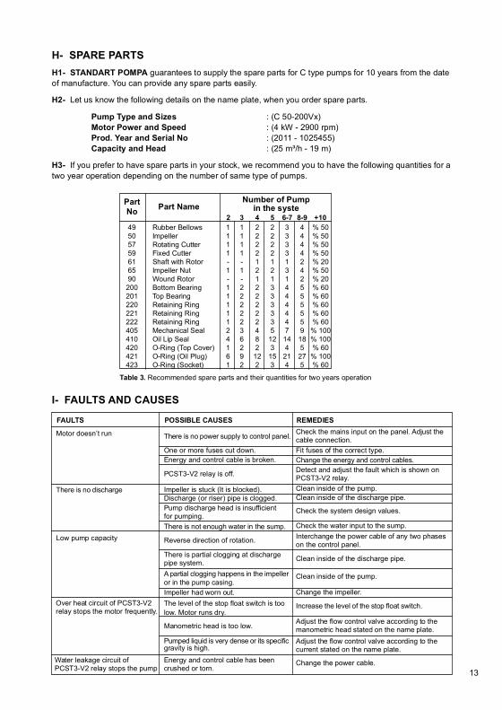
2 3 4 5 6-7 8-9 +10Part Name
Table 3. Recommended spare parts and their quantities for two years operation
ATTENTION
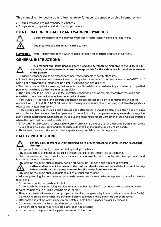
This manual is intended to be a reference guide for users of pumps providing information on
Pump installation and maintenance instructions,Pumps start-up, operation and shut - down procedures.
IDENTIFICATION OF SAFETY AND WARNING SYMBOLS Safety instructions in this manual which could cause danger to life if not observed.
The presence of a dangerous electric current.
Non – observance to this warning could damage the machine or affect its functions.
GENERAL INSTRUCTIONS
- This manual should be kept in a safe place and ALWAYS be available to the QUALIFIED operating and maintenance personnel responsible for the safe operation and maintenanceof the pumps.
- Qualified personnel should be experienced and knowledgeable of safety standards.- To avoid faulty operation and malfunctioning of pumps the instructions in this manual are to be CAREFULLYstudied and followed at all stages of the pump installation and operating life.- The user is responsible for ensuring that inspection and installation are carried out by authorized and qualifiedpersonnel who have studied this manual carefully.- The pump should be used ONLY in the operating conditions given on the order for which the pump andmaterials of the construction have been selected and tested.- If the pump is to be used for a different application please contact sales office or representative of themanufacturer. STANDART POMPA refuses to assume any responsibility if the pump used for different applicationswithout prior written permission.- If the pump is not to be installed and operated soon after arrival, it should be stored in a clean and dry placewith moderate changes in ambient temperature. Extreme low or high temperatures may severely damage thepump unless suitable precautions are taken. The user is responsible for the verification of the ambient conditionswhere the pump will be stored or installed.- STANDART POMPA does not guarantee repairs or alterations done by user or other unauthorized personnel.The use of original spare parts and accessories authorized by manufacturer will ensure safety.- This manual does not take into account any site safety regulation, which may apply.
SAFETY INSTRUCTIONS
Strictly obey to the following instructions to prevent personal injuries and/or equipment damages:
- Pump should be used only in the specified operating conditions.- Any weight, stress or strains on the piping system should not be transmitted to the pump.- Electrical connections on the motor or accessories must always be carried out by authorized personnel andin accordance to the local codes.- Any work on the pump should be only carried out when the unit has been brought to standstill.
- Always disconnect the power to the motor and make sure not be switched on accidentallybefore working on the pump or removing the pump from installation.
- Any work on the pump should be carried out by at least two persons.- When approaching the pump always be properly dressed and/or wear safety equipment suitable for the workto be done.- Do not work on the pump when it is hot.- Do not touch the pump or piping with temperatures higher than 80 ºC. User must take suitable precautionto warn the persons (e.g. using warning signs, barrier).- Always be careful when working on pumps that handling dangerous liquids (e.g. acids or hazardous fluids).- Do not work on the pump when the pump and piping connected to the pump are under pressure.- After completion of the work always fix the safety guards back in places previously removed.- Do not run the pump in the wrong direction of rotation.- Do not insert hands or fingers into the pump openings or holes.- Do not step on the pump and/or piping connected to the pump.
H- SPARE PARTSH1- STANDART POMPA guarantees to supply the spare parts for C type pumps for 10 years from the dateof manufacture. You can provide any spare parts easily.
H2- Let us know the following details on the name plate, when you order spare parts.
Pump Type and Sizes : (C 50-200Vx) Motor Power and Speed : (4 kW - 2900 rpm) Prod. Year and Serial No : (2011 - 1025455) Capacity and Head : (25 m³/h - 19 m)
H3- If you prefer to have spare parts in your stock, we recommend you to have the following quantities for atwo year operation depending on the number of same type of pumps.
I- FAULTS AND CAUSES
Check the mains input on the panel. Adjust thecable connection.Fit fuses of the correct type.Change the energy and control cables.Detect and adjust the fault which is shown onPCST3-V2 relay.Clean inside of the pump.Clean inside of the discharge pipe.
Check the system design values.
Check the water input to the sump.Interchange the power cable of any two phaseson the control panel.
Clean inside of the discharge pipe.
Clean inside of the pump.
Change the impeller.
Increase the level of the stop float switch.
Adjust the flow control valve according to themanometric head stated on the name plate.Adjust the flow control valve according to thecurrent stated on the name plate.
Change the power cable.
REMEDIES
There is no power supply to control panel.
One or more fuses cut down.
POSSIBLE CAUSES
Energy and control cable is broken.
PCST3-V2 relay is off.
Impeller is stuck (It is blocked).Discharge (or riser) pipe is clogged.Pump discharge head is insufficientfor pumping.There is not enough water in the sump.
Reverse direction of rotation.
There is partial clogging at dischargepipe system.A partial clogging happens in the impelleror in the pump casing.Impeller had worn out.The level of the stop float switch is toolow. Motor runs dry.
Manometric head is too low.
Pumped liquid is very dense or its specificgravity is high.
Energy and control cable has beencrushed or torn.
Motor doesn’t run
FAULTS
There is no discharge
Low pump capacity
Over heat circuit of PCST3-V2relay stops the motor frequently.
Water leakage circuit ofPCST3-V2 relay stops the pump 13ii

C TYPE PUMPSA- GENERALA1- Pump Description
C type submersible pumps for wet installation are single stage, single entry, close coupled pump sets innon–flameproof design.
A2- Applications
Depending on the hydraulic end, the pump is intended to be used for pumping of
Domestic wastewaterSewage disposalDirty and muddy waterIndustrial wastewaterRain waterGround water
A3- Pump Designation
C 100 - 240 B
Pump typeDischarge nozzle (DN in mm)Nominal Impeller Diameter (mm)Open Impeller
1- Pump Type and Size2- Capacity3- Head4- Motor Power5- Speed6- Impeller Diameter7- Year8- Serial Number
9- Power Factor10- Max. Ambient Temperature11- Protection Class12- Max. Submergence13- Insulation Class14- Current15- Voltage16- Frequency
A4- Pump Name Plate
All pumps can be identified by the Nameplate located on the top cover of the motor.Nameplate includes information about operating conditions.
G2- DISMANTLING THE PUMP
G2.1- Take out three of the oil and control plugs (230) which are located on the oil chamber (040) and motor(026). Completely empty the oil inside.G2.2- Detach the volute casing (001) from the motor (026) by unscrewing the four bolts (342 or 345) (Remembertaking off the cutter (057-058-059) on F - type previously).G2.3- Take off the pump impeller (050) by unscrewing the impeller nut (065). Use rust remover solvent ifnecessary during dismantling.G2.4- Be careful when taking out the rotating part of the mechanical seal (405). Do not use sharp edged orcutting tools which may tear the rubber bellow of the mechanical seal.G2.5- Take out top cover (029) of the motor by unscrewing the four bolts (340). During this operation top ballbearing (201) remains still on the rotor (061) therefore the top cover (029) should be carefully opened by usingscrew drivers.G2.6- Turn the motor upside down. Place it on a soft flat surface. Take out the bolts (342) which connect oilchamber and motor. (There are only pin screws (395) on the pumps where volute casing and motor diameteris equal and four regular bolts and two pin screws (395) on the others.)G2.7- Open up the oil chamber (040) slightly and take off cable connection of water leakage warning electrodewhich is on the rubber bellow. Use a screw driver for this operation.G2.8- Take out the oil chamber (040) with rotor bearings (200) and rubber bellows (049). Be careful not todamage the stator windings (090).G2.9- Take out the retaining ring (221) of bottom bearings by using a strong pliers. Pull of the bottom bearing(200) from oil chamber by stroking it on a wood block.G2.10- Pull off the top (201) and bottom (200) ball bearings by taking the retaining rings (220 and 222) in frontof them.G2.11- Take out the rubber bellow (049) by unscrewing the clip (390) which tightens the bellow.G2.12- Take out two oil lip seals and stationary part of mechanical seal (405) by using plastic or wooden tools.G2.13- Now, all of the pump and motor parts are dismantled. Clean all parts, replace damaged or worn-outones.G2.14- If stator windings are burnt out or are damaged, it is needed to rewind them. For this operation firstyou must break the insulation resin in which the male cable socket is placed. And after repairing the windings,the insulation resin must be refilled. This is a difficult job therefore it must be done by the experts or the completepump set must be sent to STANDART POMPA’s Repairing Workshop.
G3- REASSEMBLING THE PUMP
G3.1- Before starting the reassembly, review all the pump parts, particularly the ones listed below;1- Make sure the two faces of mechanical seals are in good condition without any scratch or dent. Replacethem with the new ones if needed.2- Clean the ball bearings and check for any wear. Replace them if needed.3- Gasket and o-ring seating faces should be checked and be rectified if they are damaged.4- Check the shaft for any wear on the sections where ball bearings, mechanical seal and oil ring is in contact.This wear must be eliminated. If not possible then the complete shaft must be changed.5- Check the energy and control cable for any tear or crush. Change it if necessary.6- Stator windings should be tested for insulation with a minimum of 500 Volts.7- Impeller and casing wear rings should be controlled for wear. If the gap between impeller and wear ringis more then 1 mm, a new wear ring shall be mounted to the casing and it shall be rectified in suitable dimension.G3.2- For reassembling the motor pump, you may find general practical technical information and bellowdrawings useful.G3.3- Reassemble the pump with care by following the reverse sequence of dismantling. Use liquid dishwashingdetergent while placing to mechanical seal for easy mounting of rubber gasket and bellow. Do not use oil.G3.4- After the completion of reassembly refill the oil chamber with oil according to instructions given onsection D2. Tighten oil plugs firmly.G3.5- Plug the cable, tighten the bolts. Turn the pump impeller by hand to check its tightness. Before loweringthe pump into sump check again the direction of rotation. Connect it to the discharge pipe and lower into thesump.
12 1
1
2
3
4
5
6
7
8
9
10
11
12131416 15

RIGHT WRONG
a. b.
F1.2- CHECKING THE CABLE INLET
1. STANDART submersible motor is connected to energy and control cable by special water tight demountablemale and female socket type system. Male socket is on the motor casing to secure a complete sealing. Themotor casing and inside of the plug are filled with insulating resin.2. In order to check the socket system, first clean the motor casing especially male and female sockets areaand dry them. Then unscrew the two connecting bolts and plug. Check the sockets to see if there is any waterinside.3. Change o-ring and plug. Make sure the gasket is placed firmly and the bolts are tightened well.
F1.3- CHECKING THE MECHANICAL SEAL
1. Lay down the motor at which one of the two oil plugs is upside and the other is downside.2. Open oil plugs and empty the oil into a clean pot.3. If the oil is clean and clear, it means the mechanical seal is in good condition. The same oil can be usedagain.4. If the oil is in yellow-gray color or it is mixed with water, it shows the mechanical seal is worn out and itneeds to be changed. In this case the WATER LEAKAGE light will be off on the motor control panel and themotor will stop.If the results of these four stages are positive, you can take down the pump into the sump.
F2- LUBRICATION AND GREASE CHANGE
1. Motor bearings are grease lubricated type. They are filled up with grease before dispatch. The greaseshould be changed after 3000 hours working or two years. It is useful to change the grease, if the pump isdismantled for any reason.2. Use high quality lithium soap grease for ball bearings.3. The oil in the oil chamber which is needed for lubricating the mechanical seal must be SAE20/SAE30 quality.4. Before changing the oil clean inside of the oil chamber and wash it with a cleaning solvent.
Table 1. Oil amount according to motor type and power
Table 2. Bearing types and grease amount according to motor type and powers
MOTOR POWER (kW) RPM PUMP TYPE OIL QUANTITY (lt)0.75 - 1.1 - 1.50.75 - 1.1 - 1.5 - 2.2
2.2 - 3 - 43 - 445.55.5 - 7.57.5 - 11
1450290014502900145029001450145029001450
C 50-160C 80-160
C 50-200
C 80-200C 50-200C 100-240C 100-240C 100-240C 100-270
0.6
1.3
1.4
2.0
2.4
2.75
0.75 - 1.1 - 1.50.75 - 1.1 - 1.5 - 2.2
RPM TOPBEARING
0.75 - 1.1 - 1.50.75 - 1.1 - 1.5 - 2.2
14502900
3 - 4 - 5.54 - 5.5
BOTTOMBEARING
GREASEcm³
7.5 - 10 - 127.5 - 10
MOTOR POWER(kW)
1450290014502900
6305 C3
6306 C3
6307 C3
10
14
20
6204-ZR
6305-ZR
6306-ZR
6
10
14
B3- Storage
If the pump is not to be installed and operated soon after arrival, store the pump in a clean, dry andfrost-free place with moderate changes in ambient temperature.To prevent the pump from moisture, dust, dirt and foreign materials suitable steps should be taken.
GREASEcm³
Figure 1. Lifting the pump property
B- UNCRATING, TRANSPORT AND STORAGEB1- Uncrating
Upon receipt verify that the goods received are in exact compliance with that listed on the packing list.Check that no visible damage exists on the crate that could have occurred during transportation.Carefully remove the packaging material and check that pump and accessories (if any) are free from anymarkings, stretches and damages, which may have occurred during transportation.In the event of damage report this immediately to STANDART POMPA’s service department and to thetransport company.
B2- Transport
B2.1- General recommendations
Existing regulations for the prevention of accidents must be followed.Wearing of gloves, hard-toed boots and hard hats is obligatory for all transport works.Wooden cases, crates, pallets or boxes may be unloaded with fork-lift trucks or using hoisting
slings, depending on their size, weight and construction.
B2.2- Lifting
Prior to lifting and moving the pump or pump and motor on a common base plate find out the following:
Total weight and center of gravityMaximum outside dimensionsLifting points location
The load-bearing capacity must be proper to the weight of the pump or the pump set.The pump or pump set must always be raised and transported in horizontal position.It is absolutely forbidden to stand beneath or nearby a raised load.A load should never remain in a raised position for longer than necessary.
G- DISMANTLING, REPAIR AND REASSEMBLYSTANDART C Type Submersible pump shall be taken to overall maintenance after two years of operation orwhen a water leakage fault occurs.
G1- PREPARATION
It is advisable that dismantling and repairing of C type pumps should be made in a workshop rather than thepump station. Take out pipe connections of the pump. Clean the outside surfaces of motor and the pump.Detach the cable socket from the motor by unscrewing the two bolts of energy and control cable. As a precaution,switch off the circuit breaker in the panel. Carry the pump to the workshop.
iii 112

C- GENERAL DESIGNSTANDART C Type Submersible sewage pumps are developed for the purpose of pumping domestic andindustrial waste water containing large solid particles. These pumps are suitable for operating entirely immersedin water. Different types of impeller are used in C Type pumps for different purposes of pumping clean andwaste water, sewage containing solids and fibrous materials, faecal material and sludge.
C1- MOTOR
Speed : 2900 rpm (50 Hz) 3500 rpm (60 Hz)
Power : Single Phase up to 1.5 kW Three Phase up to 11 kW
Insulation Class : F (155 ºC)Protection Class : IP 68Cooling Method : External water cooling
BEARINGS
Rotor and impeller are on the same shaft. The shaft is supported by two heavy duty ball bearings, which aremaintenance free for two years operation.
SHAFT SEALING
High quality silicon carbide to silicon carbide mechanical seals, which operate in oil bath, are used betweenthe motor and pumping liquid. By any reason if any water leakage occurs into the oil bath, the built-in monitoringsystem stops the motor by transmitting signals. Therefore it does not harm the motor. There are two lip-sealsbetween oil bath and motor housing.
THERMAL CONTROL SYSTEM
STANDART submersible motors are manufactured suitable for operating immersed in the water, incase themotor casing stays outside the water, it is natural that the motor starts heating up after certain period. For sucha case built-in 130 °C thermistors are placed on the stator windings in order to protect the motor. Leakageand motor heating signals are transmitted to the PCST3-V2 protection and control relay of the Motor-Controlpanel on the surface by means of auxiliary conductors of the energy cable.
CABLE CONNECTION
All sizes of STANDART Submersible motors start up directly (NOT STAR-DELTA). Therefore only three piecesof energy conductors are enough ( U-V-W ). There are also three energy cables on the single phase motors( M1-Phase, M2-Earth return and A-Capacitor conductors ). Four smaller size conductors are used for protectionand control ( E-T-T-Mp ). Energy and control cable connections are done by means of a water proof socketsystem. Inlet points of the motor casing and cable are protected by insulating resin.
C2- PUMP
STANDART C type pumps are consist of 6 casing sizes, discharge diameters are ø50, ø80 and ø100mm (2’’,3’’ and 4’’ ). Different impellers are used in these models depending on the pumping liquid, pressure, size ofthe solid particles and capacity of the pump.
Reaction
Rotation
REVERSE ROTATION
Reverse rotation of the impeller will cause undesirable problems like increase in power consumption, decreasein performance, loosening of impeller nut, scraping caused by impeller contact with casing, and etc. Therefore,before installation of the pump in the sump, the direction of rotation must be checked. Reverse rotation is nota case for single phase motors.
E2- START UP
When the control panel is energized, make sure that sure that green indicator light (NORMAL) is switched on.This indicates there is not any failure and the electrical connections are done in the right way. Pressing theSTART button or increasing of water level to the set level will start up the motor.
E3- SHUT DOWN
The motor can be shut down manually by pressing the STOP button. The motor will also automatically stopwhen the water level drops below the minimum set level. If another application will be used instead of LevelControlled Automatic Starting System, please have Standart Pompa’s approval for changed electrical diagram.Standart Pompa refuses to assume any responsibility if the pump used for different applications without priorwritten permission.
E4- STARTING FREQUENCY
In order to avoid intolerably high temperature rises within the motor, and excessive overloading of the motor,seals and bearings a maximum of 20 evenly spaced starts per hour is allowed.
F- MAINTENANCE AND LUBRICATIONSTANDART PCST3-V2 RELAY stops the pump and warns the type of fault when it is used with STANDARTC type submersible pump. But it is better to make periodical maintenance at certain times for avoiding theprobable faults; especially it is important to inspect wear in mechanical seal and the water leakage at thebeginning.
F1- PERIODICAL CONTROLS
Please checks the pump for oil and leakage at the end of the first week and the first month by taking the pumpout of the sump. If there is not any unusual situation in these controls, consequent controls can be done oncea year. If the pumping liquid is dense, corrosive or hazardous you must make periodic controls more frequently.
F1.1- CONTROL OF THE MOTOR CASING
1. STANDART submersible motor has three control plugs. Two of them are on the opposite sides of the oilchamber. The third one is at the bottom of the motor casing.2. Check the tightness of the plug on the motor housing by applying a torque on it. Then unscrew and takeoff the plug. Turning the motor as the plug hole comes facing the floor, check whether any water or oil comesout of the plug hole.3. If some water comes from the plug hole of the motor casing, it means that there is a gasket fault. But ifthere is PCST3-V2 relay in the motor control panel, ‘’WATER LEAKAGE’’ light points this and will stop themotor earlier.4. If some oil comes out from this plug hole, this means that, oil seals between oil chamber and motor casingare damaged. They must be changed. 310

OVER HEAT
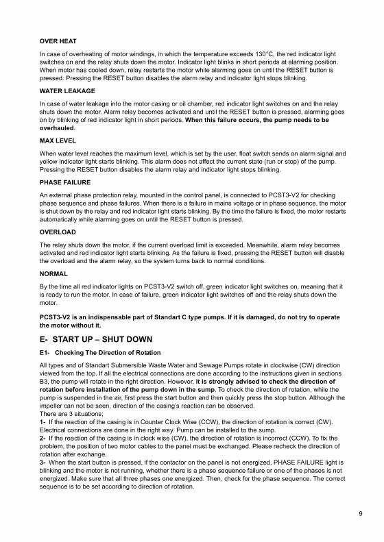
In case of overheating of motor windings, in which the temperature exceeds 130°C, the red indicator lightswitches on and the relay shuts down the motor. Indicator light blinks in short periods at alarming position.When motor has cooled down, relay restarts the motor while alarming goes on until the RESET button ispressed. Pressing the RESET button disables the alarm relay and indicator light stops blinking.
WATER LEAKAGE
In case of water leakage into the motor casing or oil chamber, red indicator light switches on and the relayshuts down the motor. Alarm relay becomes activated and until the RESET button is pressed, alarming goeson by blinking of red indicator light in short periods. When this failure occurs, the pump needs to beoverhauled.
MAX LEVEL
When water level reaches the maximum level, which is set by the user, float switch sends on alarm signal andyellow indicator light starts blinking. This alarm does not affect the current state (run or stop) of the pump.Pressing the RESET button disables the alarm relay and indicator light stops blinking.
PHASE FAILURE
An external phase protection relay, mounted in the control panel, is connected to PCST3-V2 for checkingphase sequence and phase failures. When there is a failure in mains voltage or in phase sequence, the motoris shut down by the relay and red indicator light starts blinking. By the time the failure is fixed, the motor restartsautomatically while alarming goes on until the RESET button is pressed.
OVERLOAD
The relay shuts down the motor, if the current overload limit is exceeded. Meanwhile, alarm relay becomesactivated and red indicator light starts blinking. As the failure is fixed, pressing the RESET button will disablethe overload and the alarm relay, so the system turns back to normal conditions.
NORMAL
By the time all red indicator lights on PCST3-V2 switch off, green indicator light switches on, meaning that itis ready to run the motor. In case of failure, green indicator light switches off and the relay shuts down themotor.
PCST3-V2 is an indispensable part of Standart C type pumps. If it is damaged, do not try to operatethe motor without it.
E- START UP – SHUT DOWNE1- Checking The Direction of Rotation
All types and of Standart Submersible Waste Water and Sewage Pumps rotate in clockwise (CW) directionviewed from the top. If all the electrical connections are done according to the instructions given in sectionsB3, the pump will rotate in the right direction. However, it is strongly advised to check the direction ofrotation before installation of the pump down in the sump. To check the direction of rotation, while thepump is suspended in the air, first press the start button and then quickly press the stop button. Although theimpeller can not be seen, direction of the casing’s reaction can be observed.There are 3 situations;1- If the reaction of the casing is in Counter Clock Wise (CCW), the direction of rotation is correct (CW).Electrical connections are done in the right way. Pump can be installed to the sump.2- If the reaction of the casing is in clock wise (CW), the direction of rotation is incorrect (CCW). To fix theproblem, the position of two motor cables to the panel must be exchanged. Please recheck the direction ofrotation after exchange.3- When the start button is pressed, if the contactor on the panel is not energized, PHASE FAILURE light isblinking and the motor is not running, whether there is a phase sequence failure or one of the phases is notenergized. Make sure that all three phases one energized. Then, check for the phase sequence. The correctsequence is to be set according to direction of rotation.
1- Temperature SENSOR (130°C) in F class winding head protection for overheating.2- Signaling ELECTRODE in case of leakage into the motor or into the oil chamber.3- RUBBER BELLOW balancing the pressure between the motor and oil chamber.4- Silicon-Carbide MECHANICAL SEAL running in oil bath.5- Demountable TOP COVER for easy motor winding.6- Water tight CABLE CONNECTION demountable male and female socket.7- INSULATING RESIN in order to secure definite sealing.8- Oil filling and inspection PLUGS.9- BACK VANES for reducing axial load and sealing pressure.
B type impeller : Closed type impellers with wide channels capable of pumping largesize solid particles without clogging, for big capacity and low pressure. It is more suitablefor 4 pole motors (1450 or 1750 RPM ).
D type impeller : It is also closed type, suitable for high speed motors (2900 or 3500 RPM).It is convenient for high pressure, small capacity and smaller size solid particles.
VX type impeller : Free vortex type semi-open impeller is placed on top of the volute. Itcan pump the solid particles without touching them. It is also suitable for fibrous materials.
F type impeller : Semi-open type impeller with cutter. The cutting system is placed in frontof the impeller and it breaks up the solid particles into smaller sizes that makes passingpossible through the smaller pipes without stucking. F type impeller suitable for smallcapacity, high pressure, but the pump efficiency is also low.
Figure 2. Sectional drawing for basic design
5
6
7
8
9
4
3
2
1
94

OVER HEAT
WATER LEAKAGE
MAX LEVEL
PHASE FAILURE
OVER LOAD
NORMAL RESET
PCST3-V2SUBMERSIBLE PUMP
PROTECTION AND CONTROLRELAY
POMPA ve MAKiNA SANAYi TiC. AŞ.
ATTENTION
ATTENTION
58
Figure 3. Types of installation of the pump to the sump
GATE VALVECHECK VALVE
GATE VALVECHECK VALVE
GATE VALVE
CHECK VALVEGATE VALVECHECK VALVE
CONTROL PANEL
PCST3 V2PROTECTION ANDCONTROL RELAY
CONTROL PANEL
PCST3 V2PROTECTION ANDCONTROL RELAY
CONTROL PANEL
PCST3 V2PROTECTION ANDCONTROL RELAY
CONTROL PANEL
PCST3 V2PROTECTION ANDCONTROL RELAY
3" OR 4" PIPE AND TURNSUSPENDING SYSTEM
3" OR 4" FLEXIBLE HOSE 2" FLEXIBLE HOSEmin. 800x500
START LEVEL
STOP LEVEL
HOSE CONNECTION FOR C 80 & 100 SIZE PUMPS HOSE CONNECTION FOR C 50 SIZE PUMPS
min. 500x500
START LEVEL
STOP LEVEL
min. 1200 mm min. 1200 mm
min. 600x500
START LEVEL
STOP LEVEL
min. 1500 mm
GUIDE - WIRE CONNECTION FOR C 80 & 100 SIZES PUMPS SUSPENDED CONNECTION FOR C 50 SIZE PUMPS
min. 500x500
min. 1200 mm
START LEVEL
STOP LEVEL
D- INSTALLATION OF THE PUMPD1- TYPES OF INSTALLATION
C Type submersible pumps can be installed in three different ways according to application place and purposes.When ordering the pump, installation place and the purpose or the type of installation should be indicated andthe necessary accessories should be purchased together with the pump.1- HOSE CONNECTION: In this kind of application the pump is sat on the base of the sump. Water is pumpedup to the surface by a flexible hose and can be connected to a pipe system if necessary. The pump is loweredto the sump by means of a chain. Hose connection can be applied to all sizes of C type pumps. In this applicationthe bottom of the sump should be flat and solid (in order to make the pump not to sink but to stay vertically).Necessary auxiliary parts for this application: Hose connecting union, elbow, sit-on-foot and riser chain.2- SUSPENDED CONNECTION: The pump is hanged to the inlet of the pipe system on the ground by a specialconnecting device. Pump does not sit on the base of the sump. If required, the connection elbow can be usedas a non-return valve. Suspended connecting can be applied only for ø50 mm (2’’) size pumps. It is notnecessary for sump bottom to be flat and solid for suspended connection. Suspension elbow and completesuspension set are needed for this application. In request, suspension pipe can be supplied by our factory.Suspension elbow can also be ordered with check-valve.3- GUIDE WIRE CONNECTION: In this application there should be a coupling pedestal, a riser pipe and aguide wire previously placed at the bottom of the sump. Pump is placed on the guide wire at the top, then tobe lowered by means of a chain and when it touches the coupling pedestal it is automatically coupled to thedischarge pipe system. In this application the pump does not sit on base either. This application can be appliedfor ø80-ø100 mm (3’’ - 4’’) pumps. For guide wire connection, the coupling pedestal and the discharge pipeshould be installed when the sump bottom is dry (during construction). If this installation is done later on, thesystem may not be durable enough.Necessary auxiliary parts for this application: Coupling pedestal, guide wire, stretching device, riser pipe inenough length and guide wire in enough length.
D2- Connecting The Piping
D2.1- Hose connection: A check-valve should be used right after the pump discharge hose connection pointwhich is on the ground level, A control valve should also be used if the discharge pipe is long. Hose-dischargepipe connection should be an easily dismantling type.D2.2- Suspended connection: Discharge pipe is connected directly to the coupling pedestal which is suppliedtogether with the pump for the suspended connection. If the check-valve is with connecting elbow, there isno need for a separate check-valve provided that a gate valve must be placed at the outlet and it shoulddefinitely be closed during dismantling the pump from where it is installed. If the connecting elbow is withoutcheck-valve, a check-valve and a gate valve should be used after coupling pedestal.D2.3- Guide wire connection: For guide wire type connection; discharge pipe, guide wire system, gate valveand check-valve should be installed together with coupling pedestal during construction.D2.4- General rules to be followed during pipe connections:Horizontal pipes must have the rising slope towards to the flow direction as much as possible.Pipe dimensions must be at least equal to the pump discharge dimensions. Pipe dimension must be chosenin a way that the flow velocities are between 1.5 – 3 m/s in order to avoid precipitation (caused by low flowvelocity) and extreme head losses (caused by high flow velocity).Do not use sharp bends and elbows with narrow passages, make sure the pipe inner surface is smooth andclean to avoid solid particles cause clogging.
D3- Electrical Connections
D3.1- General recommendations
1. All electrical works must be done by qualified electricians. All main electrical equipment must be earthed. Failure to heed this warning may cause lethal accident. Make sure that the earth lead is correctly connected by testing it.
2. Use Standart PCST3-V2 Motor Protection and Control Relay which is supplied with the pump. We do not guarantee the pumps running without PCST3-V2 relay.
3. Motor Control Panels must be manufactured according to the circuit diagrams in this booklet. If you use adifferent circuit diagram, please contact our technicians and have their approval.4. Make sure the currents and cable diameters of contactors, overload relays and fuses are suitable for motorsnominal currents.5. Check the mains voltage and be sure it corresponds to the value on motor label.6. Check the connection of motor cable socket and secure the tightness before initial operation.7. Connect the energy and control cable to the motor control panel complying with the colors and diametersstated in the diagrams.8. Make sure the outer cover of the energy cable is protected against damages that might be caused by sharpmetal or concrete corners and prevent it from being squeezed in narrow spaces.
Do not use the cable to lift the pump.
D3.2- PCST3-V2 MOTOR PROTECTION AND CONTROL RELAY
Standart PCST3-V2 Motor Protection and Control Relay is an indispensable part of Standart C type pumps.It is supplied with the pump and it shall be used to secure smooth operation of motor and the pump.
FUNCTIONS
When the device is switched on,all indicator lights blinks in orderand the control unit makes aself-check. If there is not anyfailure, NORMAL indicator lightswitches on in green indicatingit is ready to run the motor.

3
FKSPHASE
FAILURE
F1
RSTNMp
0F2
F3
S11 2
3 4
FKS
6
0
5
8
0
TH189
71
1
2
3
4
5
6
7
8
9
10
11
12
13
L1
MP/GND
L2
NORMAL
ALARM
E -
MAK. LEVEL
OVERLOAD
T- THERMISTOR
N
TH1PCST3 C1
PHASEFAILUREWATERLEAKAGE
0
U V W Mp E T1 T2 1 2 3 4 5 6 7
91150108 15 11 12 16 17 1876
8
8 9 10C NC NO
STOPLEVELFLOAT
ALARM
15
C1
11
PAKO
98
275V 5W
0,22MF 330OHM
N
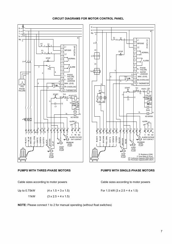
PUMPS WITH THREE-PHASE MOTORS PUMPS WITH SINGLE-PHASE MOTORS
Cable sizes according to motor powers Cable sizes according to motor powers
Up to 0.75kW (4 x 1.5 + 3 x 1.5) For 1.5 kW (3 x 2.5 + 4 x 1.5)
11kW (3 x 2.5 + 4 x 1.5)
NOTE: Please connect 1 to 2 for manual operating (without float switches)
CIRCUIT DIAGRAMS FOR MOTOR CONTROL PANEL
STOP
A M Y Mp E T1 T2 1 2 3 4 5 6 7
0 91150108 15 11 12 16 17 18
76
8
8 9 10
ALARM
021N24
C NC NOALARM VOLTAGE
15
12
13
14275V 5W
0,22MF 330OHM
N
ZR
START TH1 PCST3 CS1
C1
11
4 595 96
0
TH189
7
10
1
2
3
4
5
6
7
8
9
10
11
12
13
L1
MP/GND
L2
NORMAL
ALARM
E -
97 98
N
F2 S11 2
5
8
RNMp 0
F1
C1
23
22
TH1
N
20ZR
N
CPCDR
21
EXIT CONTACT
NO WATER
RUN
12
1314
4 595 96
97
STOP
C 100-270Vx
342
001
013
345
056
040
210
065
026
C 80-160 B
C 80-200 D
221
422
210
390
420
026
090385061
201
340
222
200
421
230
510
423344
500
220029
342
001
405
050065
C 50-160 F
220
061026
420
029 340
201
385
090
221390
025
430
342
410
405
040
343
059
065
001
057
058
210
500
344
510
423
230
421
422
200222
001 Volute Casing013 Spacer Part025 Special Flange026 Motor Casing029 Top Cover040 Oil Chamber049 Rubber Bellows050 D Type Impeller052 B Type Impeller056 Vx Type Impeller057 Rotating Cutter
058 F Type Impeller059 Fixed Cutter061 Rotor Shaft065 Impeller Nut090 Wound Stator and Rotor Set200 Bottom Bearing201 Top Bearing210 Impeller Key220 Shaft Retaining Ring221 Bearing Retaining Ring222 Shaft Retaining Ring
230 Oil Plug340 Allen Bolt342 Allen Bolt343 Allen Bolt344 Allen Bolt345 Allen Bolt346 Allen Bolt385 Set Screw390 Clip405 Mechanical Seal410 Oil Seal
420 O-Ring421 O-Ring422 O-Ring423 O-Ring430 Rubber Gasket500 Energy and Control Cable with Plug510 Plug Set
PART LIST
346 346
040
346
230
026
405
422 040
065
001 052
346
230
049 049
410
MAXIMUMLEVELFLOAT
STARTLEVELFLOAT
ALARM VOLTAGEEXIT CONTACT
STOPLEVELFLOAT
MAXIMUMLEVELFLOAT
STARTLEVELFLOAT
NO WATER
RUN
START
MAK. LEVEL
OVERLOAD
T- THERMISTOR
PHASEFAILUREWATERLEAKAGE
R: Resistance (220K)Z: Timer Relay (5-10-sn)
CP: Continuous Capacitor (400V-25mF)CD: First Action Capacitor(400V-25mF)
76
3
FKSPHASE
FAILURE
F1
RSTNMp
0F2
F3
S11 2
3 4
FKS
6
0
5
8
0
TH189
71
1
2
3
4
5
6
7
8
9
10
11
12
13
L1
MP/GND
L2
NORMAL
ALARM
E -
MAK. LEVEL
OVERLOAD
T- THERMISTOR
N
TH1PCST3 C1
PHASEFAILUREWATERLEAKAGE
0
U V W Mp E T1 T2 1 2 3 4 5 6 7
91150108 15 11 12 16 17 1876
8
8 9 10C NC NO
STOPLEVELFLOAT
ALARM
15
C1
11
PAKO
98
275V 5W
0,22MF 330OHM
N
PUMPS WITH THREE-PHASE MOTORS PUMPS WITH SINGLE-PHASE MOTORS
Cable sizes according to motor powers Cable sizes according to motor powers
Up to 0.75kW (4 x 1.5 + 3 x 1.5) For 1.5 kW (3 x 2.5 + 4 x 1.5)
11kW (3 x 2.5 + 4 x 1.5)
NOTE: Please connect 1 to 2 for manual operating (without float switches)
CIRCUIT DIAGRAMS FOR MOTOR CONTROL PANEL
STOP
A M Y Mp E T1 T2 1 2 3 4 5 6 7
0 91150108 15 11 12 16 17 18
76
8
8 9 10
ALARM
021N24
C NC NOALARM VOLTAGE
15
12
13
14275V 5W
0,22MF 330OHM
N
ZR
START TH1 PCST3 CS1
C1
11
4 595 96
0
TH189
7
10
1
2
3
4
5
6
7
8
9
10
11
12
13
L1
MP/GND
L2
NORMAL
ALARM
E -
97 98
N
F2 S11 2
5
8
RNMp 0
F1
C1
23
22
TH1
N
20ZR
N
CPCDR
21
EXIT CONTACT
NO WATER
RUN
12
1314
4 595 96
97
STOP
C 100-270Vx
342
001
013
345
056
040
210
065
026
C 80-160 B
C 80-200 D
221
422
210
390
420
026
090385061
201
340
222
200
421
230
510
423344
500
220029
342
001
405
050065
C 50-160 F
220
061026
420
029 340
201
385
090
221390
025
430
342
410
405
040
343
059
065
001
057
058
210
500
344
510
423
230
421
422
200222
001 Volute Casing013 Spacer Part025 Special Flange026 Motor Casing029 Top Cover040 Oil Chamber049 Rubber Bellows050 D Type Impeller052 B Type Impeller056 Vx Type Impeller057 Rotating Cutter
058 F Type Impeller059 Fixed Cutter061 Rotor Shaft065 Impeller Nut090 Wound Stator and Rotor Set200 Bottom Bearing201 Top Bearing210 Impeller Key220 Shaft Retaining Ring221 Bearing Retaining Ring222 Shaft Retaining Ring
230 Oil Plug340 Allen Bolt342 Allen Bolt343 Allen Bolt344 Allen Bolt345 Allen Bolt346 Allen Bolt385 Set Screw390 Clip405 Mechanical Seal410 Oil Seal
420 O-Ring421 O-Ring422 O-Ring423 O-Ring430 Rubber Gasket500 Energy and Control Cable with Plug510 Plug Set
PART LIST
346 346
040
346
230
026
405
422 040
065
001 052
346
230
049 049
410
MAXIMUMLEVELFLOAT
STARTLEVELFLOAT
ALARM VOLTAGEEXIT CONTACT
STOPLEVELFLOAT
MAXIMUMLEVELFLOAT
STARTLEVELFLOAT
NO WATER
RUN
START
MAK. LEVEL
OVERLOAD
T- THERMISTOR
PHASEFAILUREWATERLEAKAGE
R: Resistance (220K)Z: Timer Relay (5-10-sn)
CP: Continuous Capacitor (400V-25mF)CD: First Action Capacitor(400V-25mF)
76

OVER HEAT
WATER LEAKAGE
MAX LEVEL
PHASE FAILURE
OVER LOAD
NORMAL RESET
PCST3-V2SUBMERSIBLE PUMP
PROTECTION AND CONTROLRELAY
POMPA ve MAKiNA SANAYi TiC. AŞ.
ATTENTION
ATTENTION
58
Figure 3. Types of installation of the pump to the sump
GATE VALVECHECK VALVE
GATE VALVECHECK VALVE
GATE VALVE
CHECK VALVEGATE VALVECHECK VALVE
CONTROL PANEL
PCST3 V2PROTECTION ANDCONTROL RELAY
CONTROL PANEL
PCST3 V2PROTECTION ANDCONTROL RELAY
CONTROL PANEL
PCST3 V2PROTECTION ANDCONTROL RELAY
CONTROL PANEL
PCST3 V2PROTECTION ANDCONTROL RELAY
3" OR 4" PIPE AND TURNSUSPENDING SYSTEM
3" OR 4" FLEXIBLE HOSE 2" FLEXIBLE HOSEmin. 800x500
START LEVEL
STOP LEVEL
HOSE CONNECTION FOR C 80 & 100 SIZE PUMPS HOSE CONNECTION FOR C 50 SIZE PUMPS
min. 500x500
START LEVEL
STOP LEVEL
min. 1200 mm min. 1200 mm
min. 600x500
START LEVEL
STOP LEVEL
min. 1500 mm
GUIDE - WIRE CONNECTION FOR C 80 & 100 SIZES PUMPS SUSPENDED CONNECTION FOR C 50 SIZE PUMPS
min. 500x500
min. 1200 mm
START LEVEL
STOP LEVEL
D- INSTALLATION OF THE PUMPD1- TYPES OF INSTALLATION
C Type submersible pumps can be installed in three different ways according to application place and purposes.When ordering the pump, installation place and the purpose or the type of installation should be indicated andthe necessary accessories should be purchased together with the pump.1- HOSE CONNECTION: In this kind of application the pump is sat on the base of the sump. Water is pumpedup to the surface by a flexible hose and can be connected to a pipe system if necessary. The pump is loweredto the sump by means of a chain. Hose connection can be applied to all sizes of C type pumps. In this applicationthe bottom of the sump should be flat and solid (in order to make the pump not to sink but to stay vertically).Necessary auxiliary parts for this application: Hose connecting union, elbow, sit-on-foot and riser chain.2- SUSPENDED CONNECTION: The pump is hanged to the inlet of the pipe system on the ground by a specialconnecting device. Pump does not sit on the base of the sump. If required, the connection elbow can be usedas a non-return valve. Suspended connecting can be applied only for ø50 mm (2’’) size pumps. It is notnecessary for sump bottom to be flat and solid for suspended connection. Suspension elbow and completesuspension set are needed for this application. In request, suspension pipe can be supplied by our factory.Suspension elbow can also be ordered with check-valve.3- GUIDE WIRE CONNECTION: In this application there should be a coupling pedestal, a riser pipe and aguide wire previously placed at the bottom of the sump. Pump is placed on the guide wire at the top, then tobe lowered by means of a chain and when it touches the coupling pedestal it is automatically coupled to thedischarge pipe system. In this application the pump does not sit on base either. This application can be appliedfor ø80-ø100 mm (3’’ - 4’’) pumps. For guide wire connection, the coupling pedestal and the discharge pipeshould be installed when the sump bottom is dry (during construction). If this installation is done later on, thesystem may not be durable enough.Necessary auxiliary parts for this application: Coupling pedestal, guide wire, stretching device, riser pipe inenough length and guide wire in enough length.
D2- Connecting The Piping
D2.1- Hose connection: A check-valve should be used right after the pump discharge hose connection pointwhich is on the ground level, A control valve should also be used if the discharge pipe is long. Hose-dischargepipe connection should be an easily dismantling type.D2.2- Suspended connection: Discharge pipe is connected directly to the coupling pedestal which is suppliedtogether with the pump for the suspended connection. If the check-valve is with connecting elbow, there isno need for a separate check-valve provided that a gate valve must be placed at the outlet and it shoulddefinitely be closed during dismantling the pump from where it is installed. If the connecting elbow is withoutcheck-valve, a check-valve and a gate valve should be used after coupling pedestal.D2.3- Guide wire connection: For guide wire type connection; discharge pipe, guide wire system, gate valveand check-valve should be installed together with coupling pedestal during construction.D2.4- General rules to be followed during pipe connections:Horizontal pipes must have the rising slope towards to the flow direction as much as possible.Pipe dimensions must be at least equal to the pump discharge dimensions. Pipe dimension must be chosenin a way that the flow velocities are between 1.5 – 3 m/s in order to avoid precipitation (caused by low flowvelocity) and extreme head losses (caused by high flow velocity).Do not use sharp bends and elbows with narrow passages, make sure the pipe inner surface is smooth andclean to avoid solid particles cause clogging.
D3- Electrical Connections
D3.1- General recommendations
1. All electrical works must be done by qualified electricians. All main electrical equipment must be earthed. Failure to heed this warning may cause lethal accident. Make sure that the earth lead is correctly connected by testing it.
2. Use Standart PCST3-V2 Motor Protection and Control Relay which is supplied with the pump. We do not guarantee the pumps running without PCST3-V2 relay.
3. Motor Control Panels must be manufactured according to the circuit diagrams in this booklet. If you use adifferent circuit diagram, please contact our technicians and have their approval.4. Make sure the currents and cable diameters of contactors, overload relays and fuses are suitable for motorsnominal currents.5. Check the mains voltage and be sure it corresponds to the value on motor label.6. Check the connection of motor cable socket and secure the tightness before initial operation.7. Connect the energy and control cable to the motor control panel complying with the colors and diametersstated in the diagrams.8. Make sure the outer cover of the energy cable is protected against damages that might be caused by sharpmetal or concrete corners and prevent it from being squeezed in narrow spaces.
Do not use the cable to lift the pump.
D3.2- PCST3-V2 MOTOR PROTECTION AND CONTROL RELAY
Standart PCST3-V2 Motor Protection and Control Relay is an indispensable part of Standart C type pumps.It is supplied with the pump and it shall be used to secure smooth operation of motor and the pump.
FUNCTIONS
When the device is switched on,all indicator lights blinks in orderand the control unit makes aself-check. If there is not anyfailure, NORMAL indicator lightswitches on in green indicatingit is ready to run the motor.
OVER HEAT
In case of overheating of motor windings, in which the temperature exceeds 130°C, the red indicator lightswitches on and the relay shuts down the motor. Indicator light blinks in short periods at alarming position.When motor has cooled down, relay restarts the motor while alarming goes on until the RESET button ispressed. Pressing the RESET button disables the alarm relay and indicator light stops blinking.
WATER LEAKAGE
In case of water leakage into the motor casing or oil chamber, red indicator light switches on and the relayshuts down the motor. Alarm relay becomes activated and until the RESET button is pressed, alarming goeson by blinking of red indicator light in short periods. When this failure occurs, the pump needs to beoverhauled.
MAX LEVEL
When water level reaches the maximum level, which is set by the user, float switch sends on alarm signal andyellow indicator light starts blinking. This alarm does not affect the current state (run or stop) of the pump.Pressing the RESET button disables the alarm relay and indicator light stops blinking.
PHASE FAILURE
An external phase protection relay, mounted in the control panel, is connected to PCST3-V2 for checkingphase sequence and phase failures. When there is a failure in mains voltage or in phase sequence, the motoris shut down by the relay and red indicator light starts blinking. By the time the failure is fixed, the motor restartsautomatically while alarming goes on until the RESET button is pressed.
OVERLOAD
The relay shuts down the motor, if the current overload limit is exceeded. Meanwhile, alarm relay becomesactivated and red indicator light starts blinking. As the failure is fixed, pressing the RESET button will disablethe overload and the alarm relay, so the system turns back to normal conditions.
NORMAL
By the time all red indicator lights on PCST3-V2 switch off, green indicator light switches on, meaning that itis ready to run the motor. In case of failure, green indicator light switches off and the relay shuts down themotor.
PCST3-V2 is an indispensable part of Standart C type pumps. If it is damaged, do not try to operatethe motor without it.
E- START UP – SHUT DOWNE1- Checking The Direction of Rotation
All types and of Standart Submersible Waste Water and Sewage Pumps rotate in clockwise (CW) directionviewed from the top. If all the electrical connections are done according to the instructions given in sectionsB3, the pump will rotate in the right direction. However, it is strongly advised to check the direction ofrotation before installation of the pump down in the sump. To check the direction of rotation, while thepump is suspended in the air, first press the start button and then quickly press the stop button. Although theimpeller can not be seen, direction of the casing’s reaction can be observed.There are 3 situations;1- If the reaction of the casing is in Counter Clock Wise (CCW), the direction of rotation is correct (CW).Electrical connections are done in the right way. Pump can be installed to the sump.2- If the reaction of the casing is in clock wise (CW), the direction of rotation is incorrect (CCW). To fix theproblem, the position of two motor cables to the panel must be exchanged. Please recheck the direction ofrotation after exchange.3- When the start button is pressed, if the contactor on the panel is not energized, PHASE FAILURE light isblinking and the motor is not running, whether there is a phase sequence failure or one of the phases is notenergized. Make sure that all three phases one energized. Then, check for the phase sequence. The correctsequence is to be set according to direction of rotation.
1- Temperature SENSOR (130°C) in F class winding head protection for overheating.2- Signaling ELECTRODE in case of leakage into the motor or into the oil chamber.3- RUBBER BELLOW balancing the pressure between the motor and oil chamber.4- Silicon-Carbide MECHANICAL SEAL running in oil bath.5- Demountable TOP COVER for easy motor winding.6- Water tight CABLE CONNECTION demountable male and female socket.7- INSULATING RESIN in order to secure definite sealing.8- Oil filling and inspection PLUGS.9- BACK VANES for reducing axial load and sealing pressure.
B type impeller : Closed type impellers with wide channels capable of pumping largesize solid particles without clogging, for big capacity and low pressure. It is more suitablefor 4 pole motors (1450 or 1750 RPM ).
D type impeller : It is also closed type, suitable for high speed motors (2900 or 3500 RPM).It is convenient for high pressure, small capacity and smaller size solid particles.
VX type impeller : Free vortex type semi-open impeller is placed on top of the volute. Itcan pump the solid particles without touching them. It is also suitable for fibrous materials.
F type impeller : Semi-open type impeller with cutter. The cutting system is placed in frontof the impeller and it breaks up the solid particles into smaller sizes that makes passingpossible through the smaller pipes without stucking. F type impeller suitable for smallcapacity, high pressure, but the pump efficiency is also low.
Figure 2. Sectional drawing for basic design
5
6
7
8
9
4
3
2
1
94

C- GENERAL DESIGNSTANDART C Type Submersible sewage pumps are developed for the purpose of pumping domestic andindustrial waste water containing large solid particles. These pumps are suitable for operating entirely immersedin water. Different types of impeller are used in C Type pumps for different purposes of pumping clean andwaste water, sewage containing solids and fibrous materials, faecal material and sludge.
C1- MOTOR
Speed : 2900 rpm (50 Hz) 3500 rpm (60 Hz)
Power : Single Phase up to 1.5 kW Three Phase up to 11 kW
Insulation Class : F (155 ºC)Protection Class : IP 68Cooling Method : External water cooling
BEARINGS
Rotor and impeller are on the same shaft. The shaft is supported by two heavy duty ball bearings, which aremaintenance free for two years operation.
SHAFT SEALING
High quality silicon carbide to silicon carbide mechanical seals, which operate in oil bath, are used betweenthe motor and pumping liquid. By any reason if any water leakage occurs into the oil bath, the built-in monitoringsystem stops the motor by transmitting signals. Therefore it does not harm the motor. There are two lip-sealsbetween oil bath and motor housing.
THERMAL CONTROL SYSTEM
STANDART submersible motors are manufactured suitable for operating immersed in the water, incase themotor casing stays outside the water, it is natural that the motor starts heating up after certain period. For sucha case built-in 130 °C thermistors are placed on the stator windings in order to protect the motor. Leakageand motor heating signals are transmitted to the PCST3-V2 protection and control relay of the Motor-Controlpanel on the surface by means of auxiliary conductors of the energy cable.
CABLE CONNECTION
All sizes of STANDART Submersible motors start up directly (NOT STAR-DELTA). Therefore only three piecesof energy conductors are enough ( U-V-W ). There are also three energy cables on the single phase motors( M1-Phase, M2-Earth return and A-Capacitor conductors ). Four smaller size conductors are used for protectionand control ( E-T-T-Mp ). Energy and control cable connections are done by means of a water proof socketsystem. Inlet points of the motor casing and cable are protected by insulating resin.
C2- PUMP
STANDART C type pumps are consist of 6 casing sizes, discharge diameters are ø50, ø80 and ø100mm (2’’,3’’ and 4’’ ). Different impellers are used in these models depending on the pumping liquid, pressure, size ofthe solid particles and capacity of the pump.
Reaction
Rotation
REVERSE ROTATION
Reverse rotation of the impeller will cause undesirable problems like increase in power consumption, decreasein performance, loosening of impeller nut, scraping caused by impeller contact with casing, and etc. Therefore,before installation of the pump in the sump, the direction of rotation must be checked. Reverse rotation is nota case for single phase motors.
E2- START UP
When the control panel is energized, make sure that sure that green indicator light (NORMAL) is switched on.This indicates there is not any failure and the electrical connections are done in the right way. Pressing theSTART button or increasing of water level to the set level will start up the motor.
E3- SHUT DOWN
The motor can be shut down manually by pressing the STOP button. The motor will also automatically stopwhen the water level drops below the minimum set level. If another application will be used instead of LevelControlled Automatic Starting System, please have Standart Pompa’s approval for changed electrical diagram.Standart Pompa refuses to assume any responsibility if the pump used for different applications without priorwritten permission.
E4- STARTING FREQUENCY
In order to avoid intolerably high temperature rises within the motor, and excessive overloading of the motor,seals and bearings a maximum of 20 evenly spaced starts per hour is allowed.
F- MAINTENANCE AND LUBRICATIONSTANDART PCST3-V2 RELAY stops the pump and warns the type of fault when it is used with STANDARTC type submersible pump. But it is better to make periodical maintenance at certain times for avoiding theprobable faults; especially it is important to inspect wear in mechanical seal and the water leakage at thebeginning.
F1- PERIODICAL CONTROLS
Please checks the pump for oil and leakage at the end of the first week and the first month by taking the pumpout of the sump. If there is not any unusual situation in these controls, consequent controls can be done oncea year. If the pumping liquid is dense, corrosive or hazardous you must make periodic controls more frequently.
F1.1- CONTROL OF THE MOTOR CASING
1. STANDART submersible motor has three control plugs. Two of them are on the opposite sides of the oilchamber. The third one is at the bottom of the motor casing.2. Check the tightness of the plug on the motor housing by applying a torque on it. Then unscrew and takeoff the plug. Turning the motor as the plug hole comes facing the floor, check whether any water or oil comesout of the plug hole.3. If some water comes from the plug hole of the motor casing, it means that there is a gasket fault. But ifthere is PCST3-V2 relay in the motor control panel, ‘’WATER LEAKAGE’’ light points this and will stop themotor earlier.4. If some oil comes out from this plug hole, this means that, oil seals between oil chamber and motor casingare damaged. They must be changed. 310

RIGHT WRONG
a. b.
F1.2- CHECKING THE CABLE INLET
1. STANDART submersible motor is connected to energy and control cable by special water tight demountablemale and female socket type system. Male socket is on the motor casing to secure a complete sealing. Themotor casing and inside of the plug are filled with insulating resin.2. In order to check the socket system, first clean the motor casing especially male and female sockets areaand dry them. Then unscrew the two connecting bolts and plug. Check the sockets to see if there is any waterinside.3. Change o-ring and plug. Make sure the gasket is placed firmly and the bolts are tightened well.
F1.3- CHECKING THE MECHANICAL SEAL
1. Lay down the motor at which one of the two oil plugs is upside and the other is downside.2. Open oil plugs and empty the oil into a clean pot.3. If the oil is clean and clear, it means the mechanical seal is in good condition. The same oil can be usedagain.4. If the oil is in yellow-gray color or it is mixed with water, it shows the mechanical seal is worn out and itneeds to be changed. In this case the WATER LEAKAGE light will be off on the motor control panel and themotor will stop.If the results of these four stages are positive, you can take down the pump into the sump.
F2- LUBRICATION AND GREASE CHANGE
1. Motor bearings are grease lubricated type. They are filled up with grease before dispatch. The greaseshould be changed after 3000 hours working or two years. It is useful to change the grease, if the pump isdismantled for any reason.2. Use high quality lithium soap grease for ball bearings.3. The oil in the oil chamber which is needed for lubricating the mechanical seal must be SAE20/SAE30 quality.4. Before changing the oil clean inside of the oil chamber and wash it with a cleaning solvent.
Table 1. Oil amount according to motor type and power
Table 2. Bearing types and grease amount according to motor type and powers
MOTOR POWER (kW) RPM PUMP TYPE OIL QUANTITY (lt)0.75 - 1.1 - 1.50.75 - 1.1 - 1.5 - 2.2
2.2 - 3 - 43 - 445.55.5 - 7.57.5 - 11
1450290014502900145029001450145029001450
C 50-160C 80-160
C 50-200
C 80-200C 50-200C 100-240C 100-240C 100-240C 100-270
0.6
1.3
1.4
2.0
2.4
2.75
0.75 - 1.1 - 1.50.75 - 1.1 - 1.5 - 2.2
RPM TOPBEARING
0.75 - 1.1 - 1.50.75 - 1.1 - 1.5 - 2.2
14502900
3 - 4 - 5.54 - 5.5
BOTTOMBEARING
GREASEcm³
7.5 - 10 - 127.5 - 10
MOTOR POWER(kW)
1450290014502900
6305 C3
6306 C3
6307 C3
10
14
20
6204-ZR
6305-ZR
6306-ZR
6
10
14
B3- Storage
If the pump is not to be installed and operated soon after arrival, store the pump in a clean, dry andfrost-free place with moderate changes in ambient temperature.To prevent the pump from moisture, dust, dirt and foreign materials suitable steps should be taken.
GREASEcm³
Figure 1. Lifting the pump property
B- UNCRATING, TRANSPORT AND STORAGEB1- Uncrating
Upon receipt verify that the goods received are in exact compliance with that listed on the packing list.Check that no visible damage exists on the crate that could have occurred during transportation.Carefully remove the packaging material and check that pump and accessories (if any) are free from anymarkings, stretches and damages, which may have occurred during transportation.In the event of damage report this immediately to STANDART POMPA’s service department and to thetransport company.
B2- Transport
B2.1- General recommendations
Existing regulations for the prevention of accidents must be followed.Wearing of gloves, hard-toed boots and hard hats is obligatory for all transport works.Wooden cases, crates, pallets or boxes may be unloaded with fork-lift trucks or using hoisting
slings, depending on their size, weight and construction.
B2.2- Lifting
Prior to lifting and moving the pump or pump and motor on a common base plate find out the following:
Total weight and center of gravityMaximum outside dimensionsLifting points location
The load-bearing capacity must be proper to the weight of the pump or the pump set.The pump or pump set must always be raised and transported in horizontal position.It is absolutely forbidden to stand beneath or nearby a raised load.A load should never remain in a raised position for longer than necessary.
G- DISMANTLING, REPAIR AND REASSEMBLYSTANDART C Type Submersible pump shall be taken to overall maintenance after two years of operation orwhen a water leakage fault occurs.
G1- PREPARATION
It is advisable that dismantling and repairing of C type pumps should be made in a workshop rather than thepump station. Take out pipe connections of the pump. Clean the outside surfaces of motor and the pump.Detach the cable socket from the motor by unscrewing the two bolts of energy and control cable. As a precaution,switch off the circuit breaker in the panel. Carry the pump to the workshop.
iii 112

C TYPE PUMPSA- GENERALA1- Pump Description
C type submersible pumps for wet installation are single stage, single entry, close coupled pump sets innon–flameproof design.
A2- Applications
Depending on the hydraulic end, the pump is intended to be used for pumping of
Domestic wastewaterSewage disposalDirty and muddy waterIndustrial wastewaterRain waterGround water
A3- Pump Designation
C 100 - 240 B
Pump typeDischarge nozzle (DN in mm)Nominal Impeller Diameter (mm)Open Impeller
1- Pump Type and Size2- Capacity3- Head4- Motor Power5- Speed6- Impeller Diameter7- Year8- Serial Number
9- Power Factor10- Max. Ambient Temperature11- Protection Class12- Max. Submergence13- Insulation Class14- Current15- Voltage16- Frequency
A4- Pump Name Plate
All pumps can be identified by the Nameplate located on the top cover of the motor.Nameplate includes information about operating conditions.
G2- DISMANTLING THE PUMP
G2.1- Take out three of the oil and control plugs (230) which are located on the oil chamber (040) and motor(026). Completely empty the oil inside.G2.2- Detach the volute casing (001) from the motor (026) by unscrewing the four bolts (342 or 345) (Remembertaking off the cutter (057-058-059) on F - type previously).G2.3- Take off the pump impeller (050) by unscrewing the impeller nut (065). Use rust remover solvent ifnecessary during dismantling.G2.4- Be careful when taking out the rotating part of the mechanical seal (405). Do not use sharp edged orcutting tools which may tear the rubber bellow of the mechanical seal.G2.5- Take out top cover (029) of the motor by unscrewing the four bolts (340). During this operation top ballbearing (201) remains still on the rotor (061) therefore the top cover (029) should be carefully opened by usingscrew drivers.G2.6- Turn the motor upside down. Place it on a soft flat surface. Take out the bolts (342) which connect oilchamber and motor. (There are only pin screws (395) on the pumps where volute casing and motor diameteris equal and four regular bolts and two pin screws (395) on the others.)G2.7- Open up the oil chamber (040) slightly and take off cable connection of water leakage warning electrodewhich is on the rubber bellow. Use a screw driver for this operation.G2.8- Take out the oil chamber (040) with rotor bearings (200) and rubber bellows (049). Be careful not todamage the stator windings (090).G2.9- Take out the retaining ring (221) of bottom bearings by using a strong pliers. Pull of the bottom bearing(200) from oil chamber by stroking it on a wood block.G2.10- Pull off the top (201) and bottom (200) ball bearings by taking the retaining rings (220 and 222) in frontof them.G2.11- Take out the rubber bellow (049) by unscrewing the clip (390) which tightens the bellow.G2.12- Take out two oil lip seals and stationary part of mechanical seal (405) by using plastic or wooden tools.G2.13- Now, all of the pump and motor parts are dismantled. Clean all parts, replace damaged or worn-outones.G2.14- If stator windings are burnt out or are damaged, it is needed to rewind them. For this operation firstyou must break the insulation resin in which the male cable socket is placed. And after repairing the windings,the insulation resin must be refilled. This is a difficult job therefore it must be done by the experts or the completepump set must be sent to STANDART POMPA’s Repairing Workshop.
G3- REASSEMBLING THE PUMP
G3.1- Before starting the reassembly, review all the pump parts, particularly the ones listed below;1- Make sure the two faces of mechanical seals are in good condition without any scratch or dent. Replacethem with the new ones if needed.2- Clean the ball bearings and check for any wear. Replace them if needed.3- Gasket and o-ring seating faces should be checked and be rectified if they are damaged.4- Check the shaft for any wear on the sections where ball bearings, mechanical seal and oil ring is in contact.This wear must be eliminated. If not possible then the complete shaft must be changed.5- Check the energy and control cable for any tear or crush. Change it if necessary.6- Stator windings should be tested for insulation with a minimum of 500 Volts.7- Impeller and casing wear rings should be controlled for wear. If the gap between impeller and wear ringis more then 1 mm, a new wear ring shall be mounted to the casing and it shall be rectified in suitable dimension.G3.2- For reassembling the motor pump, you may find general practical technical information and bellowdrawings useful.G3.3- Reassemble the pump with care by following the reverse sequence of dismantling. Use liquid dishwashingdetergent while placing to mechanical seal for easy mounting of rubber gasket and bellow. Do not use oil.G3.4- After the completion of reassembly refill the oil chamber with oil according to instructions given onsection D2. Tighten oil plugs firmly.G3.5- Plug the cable, tighten the bolts. Turn the pump impeller by hand to check its tightness. Before loweringthe pump into sump check again the direction of rotation. Connect it to the discharge pipe and lower into thesump.
12 1
1
2
3
4
5
6
7
8
9
10
11
12131416 15
PartNo
Number of Pumpin the syste
1111-1-1111124161
49505759616590
200201220221222405410420421423
Rubber BellowsImpellerRotating CutterFixed CutterShaft with RotorImpeller NutWound RotorBottom BearingTop BearingRetaining RingRetaining RingRetaining RingMechanical SealOil Lip SealO-Ring (Top Cover)O-Ring (Oil Plug)O-Ring (Socket)
1111-1-2222236292
222212122222482
122
2222121333335
123
153
3333131444447
144
214
4444242555559
185
275
% 50% 50% 50% 50% 20% 50% 20% 60% 60% 60% 60% 60
% 100% 100% 60
% 100% 60
2 3 4 5 6-7 8-9 +10Part Name
Table 3. Recommended spare parts and their quantities for two years operation
ATTENTION
This manual is intended to be a reference guide for users of pumps providing information on
Pump installation and maintenance instructions,Pumps start-up, operation and shut - down procedures.
IDENTIFICATION OF SAFETY AND WARNING SYMBOLS Safety instructions in this manual which could cause danger to life if not observed.
The presence of a dangerous electric current.
Non – observance to this warning could damage the machine or affect its functions.
GENERAL INSTRUCTIONS
- This manual should be kept in a safe place and ALWAYS be available to the QUALIFIED operating and maintenance personnel responsible for the safe operation and maintenanceof the pumps.
- Qualified personnel should be experienced and knowledgeable of safety standards.- To avoid faulty operation and malfunctioning of pumps the instructions in this manual are to be CAREFULLYstudied and followed at all stages of the pump installation and operating life.- The user is responsible for ensuring that inspection and installation are carried out by authorized and qualifiedpersonnel who have studied this manual carefully.- The pump should be used ONLY in the operating conditions given on the order for which the pump andmaterials of the construction have been selected and tested.- If the pump is to be used for a different application please contact sales office or representative of themanufacturer. STANDART POMPA refuses to assume any responsibility if the pump used for different applicationswithout prior written permission.- If the pump is not to be installed and operated soon after arrival, it should be stored in a clean and dry placewith moderate changes in ambient temperature. Extreme low or high temperatures may severely damage thepump unless suitable precautions are taken. The user is responsible for the verification of the ambient conditionswhere the pump will be stored or installed.- STANDART POMPA does not guarantee repairs or alterations done by user or other unauthorized personnel.The use of original spare parts and accessories authorized by manufacturer will ensure safety.- This manual does not take into account any site safety regulation, which may apply.
SAFETY INSTRUCTIONS
Strictly obey to the following instructions to prevent personal injuries and/or equipment damages:
- Pump should be used only in the specified operating conditions.- Any weight, stress or strains on the piping system should not be transmitted to the pump.- Electrical connections on the motor or accessories must always be carried out by authorized personnel andin accordance to the local codes.- Any work on the pump should be only carried out when the unit has been brought to standstill.
- Always disconnect the power to the motor and make sure not be switched on accidentallybefore working on the pump or removing the pump from installation.
- Any work on the pump should be carried out by at least two persons.- When approaching the pump always be properly dressed and/or wear safety equipment suitable for the workto be done.- Do not work on the pump when it is hot.- Do not touch the pump or piping with temperatures higher than 80 ºC. User must take suitable precautionto warn the persons (e.g. using warning signs, barrier).- Always be careful when working on pumps that handling dangerous liquids (e.g. acids or hazardous fluids).- Do not work on the pump when the pump and piping connected to the pump are under pressure.- After completion of the work always fix the safety guards back in places previously removed.- Do not run the pump in the wrong direction of rotation.- Do not insert hands or fingers into the pump openings or holes.- Do not step on the pump and/or piping connected to the pump.
H- SPARE PARTSH1- STANDART POMPA guarantees to supply the spare parts for C type pumps for 10 years from the dateof manufacture. You can provide any spare parts easily.
H2- Let us know the following details on the name plate, when you order spare parts.
Pump Type and Sizes : (C 50-200Vx) Motor Power and Speed : (4 kW - 2900 rpm) Prod. Year and Serial No : (2011 - 1025455) Capacity and Head : (25 m³/h - 19 m)
H3- If you prefer to have spare parts in your stock, we recommend you to have the following quantities for atwo year operation depending on the number of same type of pumps.
I- FAULTS AND CAUSES
Check the mains input on the panel. Adjust thecable connection.Fit fuses of the correct type.Change the energy and control cables.Detect and adjust the fault which is shown onPCST3-V2 relay.Clean inside of the pump.Clean inside of the discharge pipe.
Check the system design values.
Check the water input to the sump.Interchange the power cable of any two phaseson the control panel.
Clean inside of the discharge pipe.
Clean inside of the pump.
Change the impeller.
Increase the level of the stop float switch.
Adjust the flow control valve according to themanometric head stated on the name plate.Adjust the flow control valve according to thecurrent stated on the name plate.
Change the power cable.
REMEDIES
There is no power supply to control panel.
One or more fuses cut down.
POSSIBLE CAUSES
Energy and control cable is broken.
PCST3-V2 relay is off.
Impeller is stuck (It is blocked).Discharge (or riser) pipe is clogged.Pump discharge head is insufficientfor pumping.There is not enough water in the sump.
Reverse direction of rotation.
There is partial clogging at dischargepipe system.A partial clogging happens in the impelleror in the pump casing.Impeller had worn out.The level of the stop float switch is toolow. Motor runs dry.
Manometric head is too low.
Pumped liquid is very dense or its specificgravity is high.
Energy and control cable has beencrushed or torn.
Motor doesn’t run
FAULTS
There is no discharge
Low pump capacity
Over heat circuit of PCST3-V2relay stops the motor frequently.
Water leakage circuit ofPCST3-V2 relay stops the pump 13ii

029
500
423
510
500
001
405
220
090
061
210
390
049
340
221
200
222
410
420
342
026 422
230
050
065
040
201
344
Contents
CONTENTS iGENERAL INSTRUCTIONS iiIDENTIFICATION OF SAFETY AND WARNING SYMBOLS iiSAFETY INSTRUCTIONS ii
A- GENERAL 1A1- Description of Pump 1A2- Application Areas 1A3- Pump Designation 1A4- Pump Name Plate 1
B- UNCRATING, TRANSPORT AND STORAGE 2B1- Uncrating 2
B2- Transport 2 B2.1- General Recommendations 2 B2.2- Lifting 2B3- Storage 2
C- GENERAL DESIGN 3C1- Motor 3C2- Pump 3
D- INSTALLATION 5 D1- Types of Installation 5
D2- Connecting the Piping 8 D3- Electrical Connections 8
D3.1- General Recommendations 8 D3.2- PCST3-V2 Motor Protection and Control Relay 8
E- START UP - SHUT DOWN 9E1- Checking the Direction of Rotation 9E2- Start Up 10E3- Shut Down 10E4- Starting Frequency 10
F- MEINTENANCE AND LUBRICATION 10F1- Periodical Controls 10 F1.2- Control of the Motor Casing 11 F1.3- Checking the Cable Inlet 11 F1.4- Checking the Mechanical Seal 11F2- Lubrication and Grease Change 11
G- DISMANTLING REPAIR AND REASSEMBLY 11G1- Preparation 11G2- Dismantling the Pump 12G3- Reassembling the Pump 12
H- SPARE PARTS 13I- FAULTS AND CAUSES 13J- DISASEMBLY DRAWINGS 14
346
J- DISASEMBLY DRAWINGS
i14

EC DECLARATION OF CONFORMITY
Products: Pumps of type C withManufacturer:Standart Pompa ve Makina San. Tic. A.Ş.Organize San. Bölgesi 2. Cad. No:934775 Esenkent / Ümraniye / İSTANBUL / TURKEYt: +90 216 466 89 00 f: +90 216 499 05 59www.standartpompa.com / [email protected]
The manufacturer herewith declares that the described products meet the essential requirements of MachineryDirective 2006/42/EC, Low Voltage Directive 2006/95/EC and Electromagnetic Compatibility Directive2004/108/EC.
Harmonised standards applied are;
- TS EN 809 - TS EN ISO 12100-1- TS EN 61000-6 - TS EN ISO 12100-2- TS EN 60204-1
Şeref T. ÇELEBİGeneral Vice Manager
İstanbul, 12th January 2011
The product is marked with on its name plate.
Instructions for Installation, Operation and Maintenance
Standart Pompa
All rights reserved. Can not be copied or reproduced for any purpose without permission.Subject in the manual can be changed without any prior notice.

C C SUBMERSIBLE SEWAGE & WASTE WATER PUMPS
INSTRUCTIONS FOR INSTALLATION, OPERATION & MAINTENANCE
Pump Type : ..................Serial No : ..................Capacity : ..................m³/hHead : ..................mMotor Power : ..................kWSpeed : ..................rpm
BK C 00 06-11 ENRight reserved to change without notice.No responsibility is accepted because of printing errors.
Service and Spare PartsFactory - Center