c 2005 by man-lap li. all rights reserved.rsim.cs.uiuc.edu/pubs/li.ms.thesis.pdf · distinctive...
TRANSCRIPT

c© 2005 by Man-Lap Li. All rights reserved.

DATA-LEVEL AND THREAD-LEVEL PARALLELISM IN
EMERGING MULTIMEDIA APPLICATIONS
BY
MAN-LAP LI
B.S., University of California, Berkeley, 2001
THESIS
Submitted in partial fulfillment of the requirementsfor the degree of Master of Science in Electrical Engineering
in the Graduate College of theUniversity of Illinois at Urbana-Champaign, 2005
Urbana, Illinois

ABSTRACT
Multimedia applications are becoming increasingly important for a large class of general-purpose
processors. Contemporary media applications are highly complex and demand high performance. A
distinctive feature of these applications is that they have significant parallelism, including thread-,
data-, and instruction-level parallelism, that is potentially well-aligned with the increasing paral-
lelism supported by emerging multicore architectures. Designing systems to meet the demands of
these applications therefore requires a benchmark suite comprising these complex applications and
that exposes the parallelism present in them.
This thesis makes three main contributions. First, it presents ALPBench, a publicly released
benchmark suite that pulls together five complex media applications from various sources: speech
recognition (CMU Sphinx 3.3), face recognition (CSU), ray tracing (Tachyon), MPEG-2 encode
(MSSG), and MPEG-2 decode (MSSG). We have modified the original applications to expose
thread-level parallelism using POSIX threads and data-level parallelism using Intel’s SSE2 instruc-
tions and vector extensions. Second, the thesis provides a performance characterization of the
ALPBench benchmarks, with a focus on parallelism. Such a characterization is useful for architects
and compiler writers for designing systems and compiler optimizations for these applications.
iii

ACKNOWLEDGMENTS
I would like to thank Prof. Sarita Adve, my advisor, for her invaluable guidance and support
throughout this work. Without her insights and encouragement, this work would not have been
possible. I would also like to thank Ruchira Sasanka for being a wonderful mentor and building
a user-friendly simulation platform that forms the basis of this work. I am also very thankful to
be able to collaborate with Eric Debes and Yen-Kuang Chen of Intel Corporation. Their valuable
inputs help shape the core of this work. Lastly, I would like to thank my parents for always being
supportive of my graduate study.
iv

TABLE OF CONTENTS
LIST OF TABLES . . . . . . . . . . . . . . . . . . . . . . . . . . . . . . . . . . . . . . . . . vii
LIST OF FIGURES . . . . . . . . . . . . . . . . . . . . . . . . . . . . . . . . . . . . . . . . viii
CHAPTER 1 INTRODUCTION . . . . . . . . . . . . . . . . . . . . . . . . . . . . . . . . . 1
CHAPTER 2 PARALLELISM EXPLOITED . . . . . . . . . . . . . . . . . . . . . . . . . . 42.1 ILP . . . . . . . . . . . . . . . . . . . . . . . . . . . . . . . . . . . . . . . . . . . . . 42.2 TLP . . . . . . . . . . . . . . . . . . . . . . . . . . . . . . . . . . . . . . . . . . . . . 42.3 DLP . . . . . . . . . . . . . . . . . . . . . . . . . . . . . . . . . . . . . . . . . . . . . 4
2.3.1 SIMD . . . . . . . . . . . . . . . . . . . . . . . . . . . . . . . . . . . . . . . . 52.3.1.1 SIMD programming model . . . . . . . . . . . . . . . . . . . . . . . 52.3.1.2 SIMD microarchitecture . . . . . . . . . . . . . . . . . . . . . . . . . 6
2.3.2 VoS . . . . . . . . . . . . . . . . . . . . . . . . . . . . . . . . . . . . . . . . . 72.3.2.1 VoS programming model . . . . . . . . . . . . . . . . . . . . . . . . 72.3.2.2 VoS microarchitecture . . . . . . . . . . . . . . . . . . . . . . . . . . 10
2.3.3 SVectors . . . . . . . . . . . . . . . . . . . . . . . . . . . . . . . . . . . . . . . 112.3.3.1 SVectors programming model . . . . . . . . . . . . . . . . . . . . . . 112.3.3.2 SVector microarchitecture . . . . . . . . . . . . . . . . . . . . . . . . 12
CHAPTER 3 APPLICATIONS . . . . . . . . . . . . . . . . . . . . . . . . . . . . . . . . . . 143.1 MPEG 2 Encoder (MPGenc) . . . . . . . . . . . . . . . . . . . . . . . . . . . . . . . 143.2 MPEG-2 Decoder (MPGdec) . . . . . . . . . . . . . . . . . . . . . . . . . . . . . . . 173.3 Ray Tracing (RayTrace) . . . . . . . . . . . . . . . . . . . . . . . . . . . . . . . . . . 183.4 Speech Recognition (SpeechRec) . . . . . . . . . . . . . . . . . . . . . . . . . . . . . 203.5 Face Recognition (FaceRec) . . . . . . . . . . . . . . . . . . . . . . . . . . . . . . . . 22
CHAPTER 4 METHODOLOGY . . . . . . . . . . . . . . . . . . . . . . . . . . . . . . . . . 25
CHAPTER 5 RESULTS . . . . . . . . . . . . . . . . . . . . . . . . . . . . . . . . . . . . . . 285.1 TLP . . . . . . . . . . . . . . . . . . . . . . . . . . . . . . . . . . . . . . . . . . . . . 285.2 DLP - SIMD . . . . . . . . . . . . . . . . . . . . . . . . . . . . . . . . . . . . . . . . 30
5.2.1 SIMD speedups of individual phases with SSE2 . . . . . . . . . . . . . . . . . 315.3 DLP - VoS and SVectors . . . . . . . . . . . . . . . . . . . . . . . . . . . . . . . . . . 33
5.3.1 VoS versus SIMD . . . . . . . . . . . . . . . . . . . . . . . . . . . . . . . . . . 355.3.2 VoS versus SVector . . . . . . . . . . . . . . . . . . . . . . . . . . . . . . . . . 37
5.4 ILP . . . . . . . . . . . . . . . . . . . . . . . . . . . . . . . . . . . . . . . . . . . . . 395.5 Interactions Between TLP, DLP, and ILP . . . . . . . . . . . . . . . . . . . . . . . . 40
5.5.1 Interaction between TLP and DLP . . . . . . . . . . . . . . . . . . . . . . . . 405.5.2 Interaction between DLP and ILP . . . . . . . . . . . . . . . . . . . . . . . . 41
v

5.5.3 Interaction between TLP and ILP . . . . . . . . . . . . . . . . . . . . . . . . 425.6 Sensitivity to Memory Parameters . . . . . . . . . . . . . . . . . . . . . . . . . . . . 43
5.6.1 Working sets . . . . . . . . . . . . . . . . . . . . . . . . . . . . . . . . . . . . 435.6.2 Sensitivity to memory latency or processor frequency . . . . . . . . . . . . . . 445.6.3 Memory bandwidth . . . . . . . . . . . . . . . . . . . . . . . . . . . . . . . . 46
5.7 Application-Level Real-Time Performance . . . . . . . . . . . . . . . . . . . . . . . . 47
CHAPTER 6 RELATED WORK . . . . . . . . . . . . . . . . . . . . . . . . . . . . . . . . . 48
CHAPTER 7 CONCLUSION . . . . . . . . . . . . . . . . . . . . . . . . . . . . . . . . . . . 52
REFERENCES . . . . . . . . . . . . . . . . . . . . . . . . . . . . . . . . . . . . . . . . . . . . 53
vi

LIST OF TABLES
4.1 Parameters for AlpSim. Note that several parameter values are per par-
tition or bank. . . . . . . . . . . . . . . . . . . . . . . . . . . . . . . . . . . . . . . 26
5.1 Percentage execution time and SSE2 speedup for major phases of eachapplication (except for RayTrace) on P4Sys. Small phases (i.e., phaseswith non-SSE2 execution time less than 2% or aggregates of such smallphases) where the speedup cannot be measured reliably are marked asN/A. . . . . . . . . . . . . . . . . . . . . . . . . . . . . . . . . . . . . . . . . . . . . 32
5.2 Instructions per cycle achieved on AlpSim and P4Sys for single-threadapplications. For the ALP SIMD case, the number of subword operationsretired per cycle is also given within square brackets. For P4Sys, x86microinstructions per cycle is given in parenthesis. . . . . . . . . . . . . . . . 39
5.3 Ratio NThrdSpeedupNoDLP / NThrdSpeedupDLP for 1, 4, 8, and 16 threads forall applications with DLP. . . . . . . . . . . . . . . . . . . . . . . . . . . . . . . 41
5.4 Percentage reduction of per thread IPC in the 16-thread CMP with re-spect to the IPC of 1-thread processor. The IPC does not include syn-chronization instructions or stall cycles caused by them. . . . . . . . . . . . 43
5.5 Application-level real-time performance obtained by single threaded ver-sions of our applications on a 3.06-GHz Pentium-4 processor with SSE2. . 47
vii

LIST OF FIGURES
2.1 SIMD reduction code. . . . . . . . . . . . . . . . . . . . . . . . . . . . . . . . . . . 62.2 Sum of arrays with SIMD. . . . . . . . . . . . . . . . . . . . . . . . . . . . . . . . . 72.3 Sum of arrays with VoS. . . . . . . . . . . . . . . . . . . . . . . . . . . . . . . . . . 82.4 Reduction illustrations. . . . . . . . . . . . . . . . . . . . . . . . . . . . . . . . . . . 92.5 Horizontal-first VoS reduction. . . . . . . . . . . . . . . . . . . . . . . . . . . . . . 92.6 Vertical-first VoS reduction. . . . . . . . . . . . . . . . . . . . . . . . . . . . . . . . 102.7 Sum of arrays with SVectors. . . . . . . . . . . . . . . . . . . . . . . . . . . . . . . 12
5.1 Scalability of TLP without SIMD instructions (a) with a perfect 1-cyclememory system, and (b) with realistic memory parameters. . . . . . . . . . 29
5.2 Speedup with SSE2 and ALP SIMD. . . . . . . . . . . . . . . . . . . . . . . . . 305.3 Speedups of VoS and SVector over SIMD. . . . . . . . . . . . . . . . . . . . . 335.4 Execution time distribution for SIMD, VoS, and SVector. . . . . . . . . . . 345.5 L2 cache hit rates. The rates are with SIMD for all applications except
RayTrace, for which it is without SIMD. . . . . . . . . . . . . . . . . . . . . . 425.6 L1 cache hit rates. The hit rates are with SIMD for all applications except
for RayTrace, for which it is without SIMD. . . . . . . . . . . . . . . . . . . . 435.7 Frequency Scalability. The SIMD data are with ALP SIMD for all appli-
cations. . . . . . . . . . . . . . . . . . . . . . . . . . . . . . . . . . . . . . . . . . . . 455.8 Memory bandwidth (in GB/s) at 4 GHz without SIMD. . . . . . . . . . . . 47
viii

CHAPTER 1
INTRODUCTION
Multimedia applications are becoming an important workload for general-purpose processors [1].
Emerging media applications are highly complex, incorporating increasingly intelligent algorithms
that are more control intensive than in the past and incorporating increasing functionality. These
applications demand high performance and energy efficiency. At the same time, they present
new opportunities, especially in the form of various forms of parallelism. The effective design of
processors for these applications therefore requires a benchmark suite comprising contemporary
complex media applications (versus individual kernels) and that exposes the parallelism in these
applications.
This work makes two contributions. First, it presents ALPBench, a suite of existing and emerg-
ing complex media applications, modified to expose thread-level and data-level parallelism (TLP
and DLP respectively). ALPBench is publicly available from http://www.cs.uiuc.edu/alp/alpbench/.
The current release includes five applications: speech recognition (derived from CMU Sphinx3.3 [2]),
face recognition (derived from CSU face recognizer [3]), ray tracing (same as Tachyon [4]), MPEG-
2 encode (derived from MSSG MPEG-2 encoder [5]), and MPEG-2 decode (derived from MSSG
MPEG-2 decoder [5]). We modified the original applications to expose TLP by using POSIX
threads (ray tracing was already parallelized) and to expose DLP by inserting Intel SSE2, ALP
SVectors/SStreams [6], and Vector of SIMD (VoS) instructions1 into the most commonly used rou-
tines. Both ALP SVectors/SStreams (will be referred to as SVectors) and VoS are vector extensions
of subword SIMD instructions. SVectors provides support for vector memory instructions and uses
subword SIMD instructions for computations. On the other hand, VoS is a full vector extension of
1The publicly released codes contain Intel SSE2 only.
1

subword SIMD instructions.
We believe that the applications in ALPBench will be routinely used on general-purpose proces-
sors to fulfill user requirements such as video conferencing, DVD/HDTV playback and recording,
gaming and virtual reality, authoring of home movies, authentication, and personal search/orga-
nization/mining of media/digital information. The applications chosen represent a spectrum of
media processing, covering video, speech, graphics, and image processing. The applications are all
fairly complex, especially in contrast to kernels that are often used in multimedia studies. It is
important to study these applications in their entirety because many effects are difficult to identify
in a study that only evaluates kernels [7].
The second contribution of this work is a characterization of the parallelism and performance
for the five ALPBench applications. We find that these applications contain multiple forms of
parallelism – TLP, DLP, and ILP (instruction-level parallelism). For TLP, we find that all the
applications have coarse-grain threads and most show very good thread scalability. Therefore,
these applications are a good match for emerging processors with chip-multiprocessing (CMP) and
simultaneous multithreading (SMT). For DLP, we find that four out of five of these applications
are amenable to subword SIMD instructions (SIMD for short). Many current general-purpose
processors already use such SIMD media instruction sets (e.g., MMX/SSE [8]). Furthermore,
we find that SVectors and VoS are able to effectively exploit more DLP than subword SIMD
instructions. We also investigate the interaction between different forms of parallelism (e.g., we
find that the effective exploitation of DLP reduces the effectiveness of TLP). Finally, we also
investigate the effects of the memory system on these applications, and report the different working
sets, bandwidth requirements, and memory latency tolerance in these applications.
There are several prior studies that evaluate the individual applications in ALPBench. For
instance, [9–13] characterize MPEG-2, [14–16] study Sphinx, [17] characterizes face recognition,
and [18, 19] study RayTrace. This work differs from most of the above studies because our main
focus is on studying the parallelism in these applications. Chapter 6 provides a detailed description
of the related work.
MediaBench [20], Berkeley multimedia workload [13], MiBench [21], and EEMBC [22] are several
popular benchmark suites that already target media applications. Four of the applications in
2

ALPBench are also present in one or more of the above suites (MPEG encoder and decoder [13, 20–
22], ray tracer [13], and speech recognizer [13, 20, 21]). Unlike those suites, however, ALPBench
exposes parallelism in its applications.
The rest of this thesis is organized as follows. Chapter 2 discusses the different levels of par-
allelism we exploit. Chapter 3 gives a high-level description of each application in ALPBench,
including the use of POSIX threads, subword SIMD, and VoS. Chapter 4 describes our evaluation
methodology. Chapter 5 reports our results on the characterization of our applications. Chapter 6
discusses related work.
3

CHAPTER 2
PARALLELISM EXPLOITED
This chapter describes how we exploit different levels of parallelism in ALPBench. The following
sections first briefly describe how we exploit ILP and TLP, followed by a more in-depth description
of how we exploit DLP using SIMD, VoS, and SVectors.
2.1 ILP
For ILP, we rely on the conventional out-of-order (OOO) execution mechanism that exists in most
contemporary processors. Thus, ILP is already implicit in the applications, and we did not modify
the applications for ILP support.
2.2 TLP
All the applications in ALPBench exhibit coarse-grained TLP. To exploit TLP, we use POSIX
threads. The threads usually share read-only data, requiring little additional synchronization. For
most cases, straightforward parallelization was sufficient for the relatively small systems we consider
(e.g., static scheduling of threads).
2.3 DLP
This section compares the programming model and describes the microarchitectures of three dif-
ferent types of DLP processors: subword SIMD capable modern processors (Intel Pentium 4 and
ALP SIMD), VoS, and ALP SVectors/SStreams [6].
4
For the rest of the section, subword SIMD capable modern processors will be referred to as
SIMD, and subword SIMD instructions and subword SIMD registers will be called SIMD instruc-
tions and SIMD registers, respectively.
When describing the programming model, the issue of reductions is also discussed. A reduction
applies the same operation to multiple data elements and produces one element. Typical reduction
operations include sum, average, min, max, etc. As ALPBench applications exhibit a significant
number of reduction operations, it is important to understand how they are handled in these DLP
architectures.
For the rest of the thesis, we define a horizontal reduction as reducing packed elements in a
SIMD register into one element (e.g., sum of four 32-bit floating point numbers in a 128-bit SIMD
register that yields one floating point number). On the other hand, a vertical reduction reduces
multiple SIMD registers into one SIMD register (e.g., sum of an array of packed words which results
in one packed word). In all of the programming models described in this chapter, both the vertical
reduction and the horizontal reduction are described.
2.3.1 SIMD
This section describes the programming models and microarchitectures of Intel SSE2 and ALP
SIMD. ALP SIMD, a subword SIMD instruction set roughly modeled after Intel SSE2, is introduced
in [6] to study DLP of ALPBench applications in AlpSim simulation environment (Chapter 4). Since
ALP SIMD runs on a simulator, we are able to characterize the applications in greater details (e.g.,
branch predictions, cache misses, register pressure, etc.). Further, it can be compared with VoS
and ALP SVectors/SStreams directly because they all use AlpSim.
2.3.1.1 SIMD programming model
Many of the modern general-purpose processors provide SIMD instructions for exploiting DLP.
These SIMD instructions operate on SIMD registers that store multiple data elements. Both Intel
SSE and ALP SIMD offer eight 128-bit architectural SIMD registers that can store two 64-bit, four
32-bit, eight 16-bit, or sixteen 8-bit data elements. SIMD instructions exploit DLP by operating on
multiple data elements in the SIMD registers simultaneously. The most common opcodes supported
5

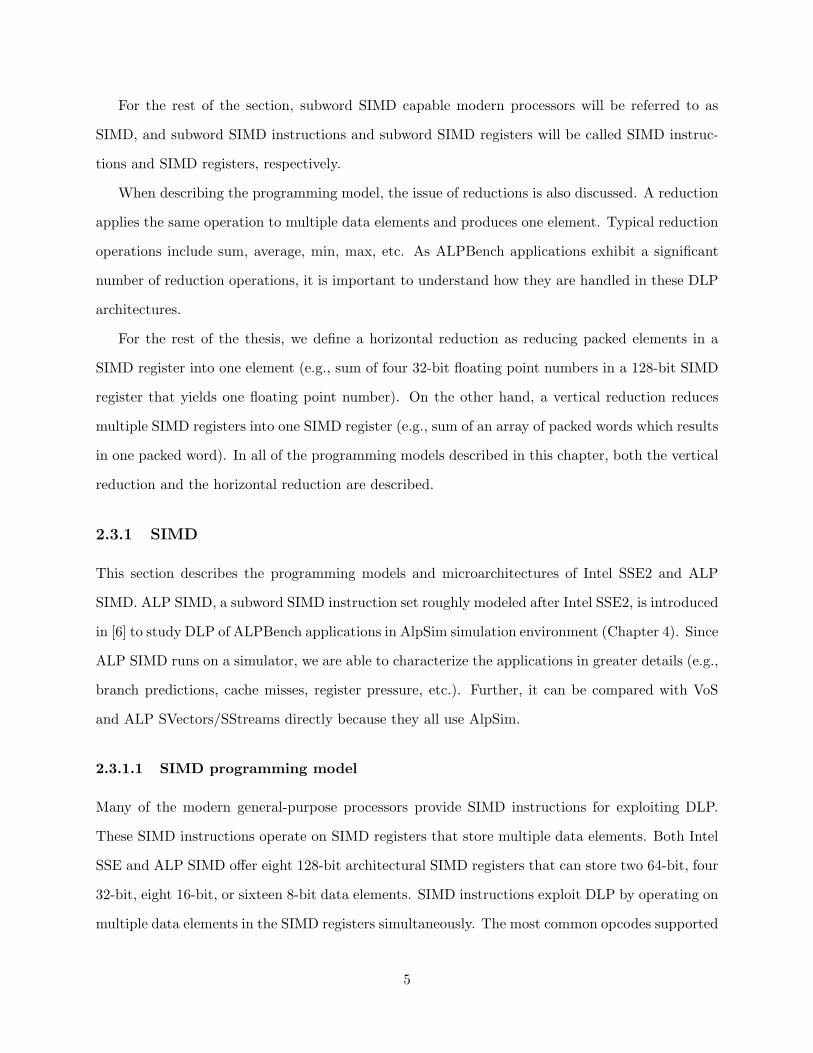
/* dot product of two vectors with 4N floats, each SIMD reg holds 4 floats */
initialize s3 for accumulation
for N times loop
simd_load r1 -> s0
simd_load r2 -> s1
simd_mul s0, s1 -> s2 /* multiply packed elements in s0 and s1, write s2*/
simd_add s3, s2 -> s3 /* s3 contains the partial dot product */
inc r1 and r2
end loop
/* s3 has 4 partial dot products, need to do horizontal reduction */
simd_red s3 -> s4
Figure 2.1 SIMD reduction code.
by both Intel SSE2 and ALP SIMD are packed addition, subtraction, multiplication, absolute
difference, average, horizontal reduction, logical, and pack/unpack operations.
We use SIMD instructions to vectorize the innermost loops of the DLP kernels. Because all
of the kernels found in ALPBench’s DLP applications originally have two or more dimensions of
loops, vectorizing the innermost loops results in loops of SIMD instructions. For the rest of the
thesis, these loops will be referred to as SIMD loops.
Reduction: Vertical reductions are handled by SIMD instructions within a SIMD loop and a
SIMD register used as an accumulator. Horizontal reductions are carried out with a SIMD reduce
instruction (e.g., sum, min, max, etc.). Figure 2.1 shows one of the very common reduction opera-
tions, the dot-product. The SIMD add within the loop is performing a vertical reduction while the
last SIMD reduce instruction horizontally reduces the data elements in s3 to a dot-product.
2.3.1.2 SIMD microarchitecture
The following briefly describes how SIMD instructions are supported in Pentium 4 and ALP SIMD,
respectively.
Intel Pentium 4: Intel Pentium 4’s [23] SSE2 instructions are executed in the floating-point
pipeline. Since the floating-point execution units are 64-bit wide and the SIMD registers are 128-
bit wide, SIMD instructions always take at least two cycles to complete.
ALP SIMD: Like Intel Pentium 4, ALP SIMD also executes SIMD instructions in the floating-
point pipeline and uses 128-bit wide SIMD registers. However, the floating-point/SIMD units are
128-bit wide and thus able to complete low-latency SIMD instructions (e.g., integer SIMD add,
6

/* int A[N], B[N], C[N];
r4 = address of C
r5 = address of A
r6 = address of B
*/
for i = 1 to (N/4)
simd_load [r5] -> r2 /* load 4 elements from A and B */
simd_load [r6] -> r3
simd_add r2, r3 -> r3 /* A[i]+B[i],...,A[i+3]+B[i+3] */
simd_store r3 -> [r4] /* store the 4 sums to C */
add r5, 16 -> r5 /* increment address pointers */
add r6, 16 -> r6
add r4, 16 -> r4
end for
Figure 2.2 Sum of arrays with SIMD.
subtract, logical, etc.) in one cycle.
For both Pentium 4 and ALP SIMD, the register renaming, instruction scheduling, and in-
struction retirement of SIMD instructions are similar to other floating point instructions. The only
difference is that ALP SIMD assumes a more aggressive SIMD unit and, therefore, lower execution
latencies. The architectural parameters of ALP SIMD are presented in Table 4.1 of Chapter 4.
2.3.2 VoS
2.3.2.1 VoS programming model
VoS stands for Vector of SIMD and is a full vector extension of the SIMD instruction set. The
opcodes of the vector version of ALP SIMD instructions are supported in VoS. The VoS instructions
operate on VoS registers, which are arrays of SIMD registers. In VoS ISA, there are eight archi-
tectural VoS registers and two control registers: vector length (vlen) and vector stride (vstride).
Each VoS register can store 64 128-bit words. The vector length register controls the number of
SIMD words to be processed by each VoS instruction and the vector stride register controls the
strided memory accesses of VoS load and store instructions. VoS does not support gather/scatter
operations since we did not find the need for these operations for our applications.
Figure 2.2 and Figure 2.3 show the code for summing two integer arrays in SIMD and VoS,
respectively. When compared with SIMD, a sequence of VoS instructions instead of a SIMD loop
is used. Consequently, VoS has the fewest dynamic instructions.
Most of the SIMD loops can be directly converted to VoS code sequences. If the number of
7

/* int A[N], B[N], C[N];
r4 = address of C
r5 = address of A
r6 = address of B
M = N/4 (assume M <= max VoS vector length)
*/
set_vstride 16 /* Set Stride to 16 bytes for unit stride access */
set_vlen M /* Set the vector length for the VoS instr */
vos_load [r5] -> v0 /* Load M records from A and B */
vos_load [r6] -> v1
vos_add4 v0, v1 -> v2 /* A[0]+B[0], ..., A[M-1]+B[M-1] */
vos_store v2 -> [r4] /* Store the result to C */
Figure 2.3 Sum of arrays with VoS.
SIMD loop iterations is less than or equal to the maximum vector length (MAXVL), we simply set
the number of SIMD loop iterations as the vector length and convert the SIMD instructions into
their VoS counterparts (e.g., from simd add to vos add). If the number of iterations is larger than
MAXVL, the SIMD loop is appropriately stripmined.
Reduction: Each element of a VoS register can be horizontally reduced with the vector horizontal
reduction instruction (vos red). For vertical reductions, tree reductions are used.
A simple method for tree reductions is to repeatedly store the vector to memory, load back the
second half of the vector into another VoS register, and reduce the two half vectors into one. How-
ever, the vector loads and stores inherently limit the reduction performance. Cray C90, therefore,
introduced the “vector word shift” instruction that moves the end of one vector register to the
start of another. Subsequently, Asanovic et al. used the same concept and introduced the “vector
extract” instruction to improve the T0 processor’s [24] reduction performance. Given the large
number of reduction operations for multimedia applications, VoS also includes the vector extract
(vextv) instruction.
The instruction vextv takes a scalar register and a VoS register as source operands. The scalar
operand is the index to the source VoS register, and vextv moves the vector starting at the specified
index to the destination VoS register. The length of the extracted vector is determined by the vector
length register.
To reduce a VoS register into a scalar value, both a vertical reduction and a horizontal reduction
are needed. Hence, there are two ways: vertical first and horizontal first. Figure 2.4 illustrates the
steps involved in both approaches. A simple analysis shows that the vertical-first approach yields
8

Figure 2.4 Reduction illustrations.
/* assume v0 is a VoS of length N */
r1 = N
set_vlen N
vos_red v0 -> v0 /* horizontal reduction */
while (r1>1) {
shift_right r1, 1 -> r1 /* half the vector length */
set_vlen r1
vextv r1, v0 -> v1 /* extract half of the vector from v0 and
write it to v1 */
vos_add v0, v1 -> v0 /* reduce! */
}
Figure 2.5 Horizontal-first VoS reduction.
fewer number of operations as follows.
In order to reduce a vector of SIMD words of length N with the horizontal-first approach,
vos red of vector length N is first used and the resulting vector is vertically reduced as shown in
Figures 2.4(a) and 2.5. In the vertical-first approach, a SIMD packed word results from the vertical
reduction and is subsequently horizontally reduced with vos red (Figures 2.4(b) and 2.6).
As there are equal number of operations in the vertical reduction loop, the difference comes
from the vector lengths of the vos red instructions. This difference is illustrated in Figure 2.4.
In (a), the horizontal reduction is the vos red instruction with vector length set to N. In (b), the
vector length of the vos red is only 1. Clearly, the vertical-first approach is likely to have better
performance. However, in the case when N is smaller than or equal to the number of vector lanes,
both approaches yield the same performance.
9

/* assume v0 is a VoS of length N */
r1 = N
while (r1>1) {
shift_right r1, 1 -> r1 /* half the vector length */
set_vlen r1
vextv r1, v0 -> v1 /* extract half of the vector from v0 and
write it to v1 */
vos_add v0, v1 -> v0 /* reduce! */
}
set_vlen 1
vos_red v0 -> v0 /* horizontal reduction */
Figure 2.6 Vertical-first VoS reduction.
2.3.2.2 VoS microarchitecture
As the VoS ISA targets emerging multimedia applications that are becoming increasingly impor-
tant in general-purpose processing, it is essential for VoS to be integrated with a general-purpose
processor. Tarantula [25] is a novel architecture that integrates an Alpha EV8 core with a vec-
tor unit and has been shown to perform well for scientific and engineering applications. In order
to explore how a similar vector architecture would perform in multimedia applications, the VoS
microarchitecture is modeled after Tarantula.
In VoS, the scalar core (SCore) is responsible for renaming the VoS registers of VoS instructions,
sending the instructions to the VoS unit (VCore), and retiring them. When the VCore receives an
instruction, it inserts the instruction into either the load store queue (VLSQ) or the issue queue
(VIQ) depending on the type of the VoS instruction. Both VLSQ and VIQ are dual-issue. Then,
after the instruction is processed, the VCore signals the SCore to indicate that the instruction is
ready for retirement. Upon branch misprediction, the SCore sends a kill signal to flush the vector
pipeline. Furthermore, there is a 10-cycle data transfer latency between the SCore and the VCore.
The VCore consists of 4 independent lanes. Each lane has a slice of the VoS register file, 2
functional units, an address generation unit (AGU), and a TLB. While there are 8 functional units
in VCore, they only appear as 2 resources (referred to as the north and south ports for Tarantula).
Thus, the VoS register file in each lane only needs 4 read ports and 2 write ports for the functional
units.
After a VoS memory instruction is issued from VLSQ, its memory addresses are generated in
the AGU and looked up in the TLB in each lane. Then, the memory requests of the VoS memory
10
instruction are sent to the L2 cache. For VoS loads, the L2 cache sends the vector elements back to
the VCore as soon as they become available, possibly out of order. As the time of availability of the
different vector elements is unpredictable, VoS does not chain dependent VoS compute instructions
with a VoS load (similar to Tarantula). Moreover, as the DLP sections of the ALPBench appli-
cations need only strided access support, scatter/gather memory instructions are not introduced.
However, VoS can be augmented with such support as described in [25].
For two dependent VoS compute instructions, VoS supports flexible chaining. Thus, a dependent
compute instruction can start executing as soon as the next vector elements of the source operands
(from a previous compute instruction) are ready regardless of whether they are produced from the
execution unit or the register file.
To support the vector extract instruction, a barrel shifter is added between the L2 cache and the
VCore for interlane communication. There is a 4-cycle interlane communication latency. However,
this communication overhead occurs only if the extract index is not a multiple of 4 (the number
of lanes in VoS). If the extract index is a multiple of 4, the source and destination SIMD registers
within the VoS registers are already in the same lane and no interlane communication is needed.
More architectural parameters of VoS can be found in Table 4.1.
2.3.3 SVectors
2.3.3.1 SVectors programming model
ALP [6] introduces the novel SVectors and SStreams programming models. The SVectors model lies
between SIMD and conventional vectors and seeks to provide most of the benefits of pure vectors
with lower cost for multimedia applications. SVectors exploit the regular data access patterns
that are the hallmark of DLP by providing support for conventional vector memory instructions.
They differ from conventional vectors in that computation on vector data is performed by existing
SIMD instructions. Each of the 8 architectural SVector registers (SVRs) is associated with an
internal hardware register that indicates the “current” element of the SVector. A SIMD instruction
specifying an SVR as an operand accesses and auto-increments the current element of that register.
Thus, a loop containing a SIMD instruction accessing an SVR, say V0, marches through V0, much
11

/* int A[N], B[N], C[N];
r4 = address of C
r5 = address of A
r6 = address of B
M = N/4 (assume M <= max SVector length)
*/
set_vstride 16 /* the heads of records are 16 bytes apart */
svector_load:M [r5] -> v0 /* load M SIMD words from A to v0 */
svector_load:M [r6] -> v1 /* load M SIMD words from B to v1 */
svector_alloc:M [r4] -> v2 /* allocate M SIMD words for v2,
tag v2 with C’s addr for writeback */
for i = 1 to (N/4)
simd_add v0, v1 -> v2 /* add 4 elements from A and B */
end for
Figure 2.7 Sum of arrays with SVectors.
like a vector instruction. SStreams are similar to SVectors except that they may have unbounded
length.
Figure 2.7 shows the SVector code that computes the sum of two integer arrays. The svector load
instructions bring data into the SVRs v0 and v1. The svector alloc instruction reserves a write-
back register and tags it with C’s memory location. The SIMD add instruction reads SVRs v0 and
v1 sequentially and writes back to v2. Writing to v2 causes data to be stored back to memory
automatically.
Compared with Figure 2.2, SVector loads replace the SIMD loads inside the SIMD loop. Thus,
the use of SVector loads results in reduction of dynamic instruction count since SIMD memory in-
structions and their overhead instructions (index increments) within the SIMD loop are eliminated.
Further, the larger register space offered by SVectors allows significantly higher load latency toler-
ance through aggressive load scheduling and preloading. Using conventional SIMD instructions for
computation allows use of conventional processors with small modifications. In [6], Sasanka et al.
describe the benefits of SVectors over SIMD in more detail.
Reduction: As ALP uses SIMD compute instructions, the reduction procedure is the same as in
SIMD. The difference is that SVector loads instead of SIMD loads are used to bring in the data.
2.3.3.2 SVector microarchitecture
To support SVectors and SStreams, Sasanka et al. [6] employ a reconfigurable L1 data cache for
the SVector register file. The L1 cache is enhanced with an SVector descriptor table to host the
12

SVRs. Data are brought in and written out through the L2 cache. To simplify the allocation and
deallocation of SVRs, the SVector architecture uses a writethrough L1 cache and each cacheline is
tagged with a bit to indicate whether an SVR is present.
An SVector descriptor consists of the location of the SVR in the L1 cache, the vector length,
the vector stride, the current record pointer (CRP), the associated base memory address, and the
last available record pointer. For every SVector load and allocate instruction, an SVR is allocated
in the L1 cache and the location is written into the descriptor, along with the memory address,
vector length, and the vector stride. When data comes back for an SVector load, the last available
record pointer is updated. Subsequently, as the SIMD instructions use SVRs as source registers,
their CRPs are incremented. Since SIMD instructions access the SVRs sequentially, they can start
executing as soon as the records to which the CRPs point are available. More details appear in [6].
13

CHAPTER 3
APPLICATIONS
This chapter describes our applications and the enhancements we made to them. The programming
models for exploiting TLP and DLP are described in Chapter 2’s Section 2.2 and Section 2.3
respectively. In some cases, we also made a few algorithmic modifications to the original applications
to improve performance.
The following descriptions provide a summary of algorithmic modifications (where applicable),
major data structures, application phases, thread support, subword SIMD support, and VoS sup-
port. Since SVectors use SIMD instructions for computations, the subword SIMD support also
applies to SVectors. Additionally, the loads in the SIMD loops are converted to vector memory
(SVectors) instructions similar to VoS, except for FaceRec which uses SStreams.
3.1 MPEG 2 Encoder (MPGenc)
We use the MSSG MPEG-2 encoder [5]. MPGenc converts video frames into a compressed bit-
stream. A video encoder is an essential component in VCD/DVD/HDTV recording, video editing,
and video conferencing applications. Many recent video encoders like MPEG-4/H.264 use similar
algorithms.
A video sequence consists of a sequence of input pictures. Input images are in the YUV format;
i.e., one luminance (Y) and two chrominance (U,V) components. Each encoded frame is charac-
terized as an I, P, or B frame. I frames are temporal references for P and B frames and are only
spatially compressed. On the other hand, P frames are predicted based on I frames, and B frames
are predicted based on neighboring I and P frames.
14

Modifications: We made two algorithmic modifications to the original MSSG code: (1) we use
an intelligent three-step motion search algorithm [26] instead of the original full-search algorithm
and (2) we use a fast integer discrete cosine transform (DCT) butterfly algorithm based on the
Chen-Wang algorithm [27] instead of the original floating point matrix-based DCT.
Data Structures: Each frame consists of 16x16 pixel macroblocks. Each macroblock consists of
four 8x8 luminance blocks and two 8x8 chrominance blocks, one for U and one for V.
Phases: The phases in MPEG-2 include motion estimation (ME), quantization, discrete cosine
transform (DCT), variable length coding (VLC), inverse quantization, and inverse DCT (IDCT).
The first frame is always encoded as an I-frame. For an I-frame, the compression starts with
DCT. DCT transforms blocks from the spatial domain to the frequency domain. Following DCT
is quantization that operates on a given 8x8 block, a quantization matrix, and a quantization
value. The operations are performed on each pixel of the block independent of each other. After
quantization, VLC is used to compress the bit stream. VLC uses both Huffman and run-length
coding. This completes the compression.
For predictive (P and B) frames, the compression starts with motion estimation. In motion
estimation, for each macroblock of the frame being currently encoded, we search for a “best-
matching” macroblock within a search window in a previously encoded frame. The distance or
“match” between two macroblocks is computed by calculating the sum of the differences between
the pixels of the blocks. The original “full-search” algorithm performs this comparison for all
macroblocks in the search window. Instead, we use a three-step search algorithm which breaks
a macroblock search into three steps: (i) search at the center of the search window, (ii) search
around the edges of the search window, and (iii) search around the center of the search window.
A subsequent step is taken only if the previous step does not reveal a suitable match. Motion
estimation is the longest (most compute intensive) phase for P and B frames. The rest of the
compression for P and B frames is the same as that for an I-frame.
For processing subsequent frames, it is necessary to decode the encoded frame. For this purpose,
inverse quantization and inverse DCT are applied to the encoded frame. These inverse operations
15

have the same properties as their forward counterparts.
We removed the rate control logic from this application. The original implementation performs
rate control after each macroblock is encoded, which imposes a serial bottleneck. For the threaded
version, rate control at the end of a frame encoding would be more efficient but we did not imple-
ment this.
Threads: We create a given number of threads at the start of a frame and join them at the end
of that frame. Within a frame, each thread encodes an independent set of contiguous macroblock
rows in parallel. Each thread takes such a set through all the listed phases and writes the encoded
stream to a private buffer. Thread 0 sequentially writes the private buffers to the output.
SIMD: Integer SIMD instructions are added to all the phases except VLC. 8b (char) subwords
are used in macroblocks; 16b (short) words are used to maintain running sums. The main SIMD
computation in motion estimation is a calculation of sum of absolute difference (SAD) between two
128b packed words of two macroblocks. psad (packed SAD) instructions in SSE2 are used for this
purpose. The result of the sad is accumulated with SIMD add (sadd) in a register. For half pixel
motion estimation, it is necessary to find the average of two 128b records. This is achieved using
pavg (packed average) SSE2 instructions.
We obtained SSE2 code for DCT and IDCT from [28] and [29] respectively, and both the DCT
and IDCT computations use the optimized butterfly algorithm based on the works of [27] and [30].
Subword sizes of 16b (short) are used for DCT/IDCT and multiply accumulate instructions are used
for common multiply accumulate combinations in this code. Quantization and inverse quantization
involve truncation operations. We use packed minimum and packed maximum for performing the
truncations [8].
Before DCT and after IDCT, the encoder performs a block subtraction and a block addition
where a block of frequency deltas are added or subtracted from a block. We use packed saturated
addition and subtraction for these operations.
VoS: Integer VoS instructions are inserted in all the phases except VLC, DCT, and IDCT. For
16

DCT and IDCT, recall that the SIMD-enhanced versions used the optimized butterfly algorithm.
This algorithm is not amenable to vectorization because of its irregular data accesses. We tried
a simple matrix-based algorithm which is amenable to vectorization, but found that the SIMD-
enhanced optimized version performed better. This finding shows that algorithmic optimizations
are important in enhancing DLP kernels.
In motion estimation, vector sad (vsad) and vector pavg (vpavg) are heavily used. For half
pixel estimation, the vpavg of the source VoS registers is first computed. Then, vsad is used to find
the sum of differences between the two macroblocks. After that, reduction operations with vector
sadd (vsadd) are applied to produce an aggregate sum.
Unlike motion estimation, block truncations (in quantization and inverse quantization), sub-
tractions, additions, and saturations do not involve reduction operations. Therefore, they are
seamlessly enhanced with VoS instructions.
3.2 MPEG-2 Decoder (MPGdec)
We use the MSSG MPEG-2 decoder [5]. MPGdec decompresses a compressed MPEG-2 bit-stream.
Video decoders are used in VCD/DVD/HDTV playback, video editing, and video conferencing.
Many recent video decoders, like MPEG-4/H.264, use similar algorithms.
Data Structures: Same as for MPGenc.
Phases: Major phases for MPGdec include variable length decoding (VLD), inverse quantization,
IDCT, and motion compensation (MC).
The decoder applies the inverse operations performed by the encoder. First, it performs variable-
length Huffman decoding. Second, it inverse quantizes the resulting data. Third, the frequency-
domain data is transformed with IDCT to obtain spatial-domain data. Finally, the resulting blocks
are motion-compensated to produce the original pictures.
Threads: At first glance, this application seems to be serial since frames have to be recovered by
decoding blocks one by one from the encoded bit stream. However, a closer look at the application
17

shows that the only limitation of exploiting TLP for this application is the serial reads from the
bit stream and the rest can be readily parallelized.
In our implementation, thread 0 identifies the slices (contiguous rows of blocks) in the input
encoded bit-stream. When a given number of slices is identified, those slices are assigned to a new
thread for decoding. Due to this staggered nature of creating threads, different threads may start
(and finish) at different times, thereby reducing the thread-level scalability of the application.
Each thread takes each block in a slice through all the phases listed above and then writes each
decoded block into a nonoverlapping region of the output image buffer.
SIMD: Integer SIMD instructions are added to IDCT and motion compensation. IDCT uses the
same SIMD code used in MPGenc. Motion compensation contains subfunctions like block pre-
diction, add-block (adding the reference block and error (frequency deltas)) and saturate. Block
prediction finds the reference blocks based on motion vectors in the bitstream. For full-pixel pre-
dictions, SIMD loads and stores are used. For half-pixel predictions, pavg instructions are used
prior to the SIMD stores. Add-block and saturate operations are performed using packed addition
with saturate on 16b words.
VoS: Integer VoS instructions are added to motion compensation only. For IDCT, the SIMD-
enhanced version is used as explained in MPGenc’s VoS section.
The block predictions are enhanced with vpavg (for half-pixel predictions) and vector sadd
(vsadd). The block additions and saturations are enhanced with vector sadd (vsadd) and vector
SIMD saturate (vssat) instructions respectively.
3.3 Ray Tracing (RayTrace)
We use the Tachyon ray-tracer [4]. A ray-tracer renders a scene using a scene description. Ray
tracers are used to render scenes in games, 3-D modeling/visualization, virtual reality applications,
etc.
The ray tracer takes in a scene description as input and outputs the corresponding scene. A
scene description normally contains the location and viewing direction of the camera, the locations,
18

shapes, and types of different objects in the scene, and the locations of the light sources.
Data Structures: The constructed scene is a grid of pixels. The pixels are colored based on the
light sources and objects in the scene. The objects are maintained in a linked list. The color of
each pixel is determined independently.
Phases: This application does not have distinct phases at a high level. At start, based on the
camera location and the viewing direction specified, the viewing plane is created to represent the
grid of pixels to be projected from the scene to the resulting picture. To project the correct color
for each pixel, a ray is shot from the camera through the viewing plane into the scene. The ray is
then checked against the list of objects to find out the first object that the ray intersects. After
that, the light sources are checked to see if any of the light rays reach that intersection. If so,
the color to be reflected is calculated based on the color of the object and the color of the light
source. The resulting color is assigned to the pixel at where the camera ray and the viewing plane
intersect. Moreover, since objects can be reflective or transparent, the ray may not stop at the first
object it intersects. Instead, the ray can be reflected or refracted to other directions until another
object is intersected. In that case, the color of the corresponding pixel is determined by repeatedly
reflecting/refracting the ray at each surface.
Threads: Each thread is given N independent rays to trace, where N is the total number of pixels
in the viewing plane divided by the number of threads in the system.
SIMD and VoS: No DLP support is added since the various computations done on each ray can
be quite different from neighboring rays. This is because neighboring rays can intersect different
objects leading to different computations (operations) with each ray. Further, there is no DLP
within each ray since each ray performs control intensive operations.
19

3.4 Speech Recognition (SpeechRec)
We use the CMU SPHINX3.3 speech recognizer [2]. A speech recognizer converts speech into text.
Speech recognizers are used with communication, authentication, and word processing software and
are expected to become a primary component of the human-computer interface in the future.
Data Structures: The major data structures used include:
(1) 39-element feature vectors extracted from an input speech sample. We modify them to 40
elements for aligned SIMD computations.
(2) Multiple lexical search trees built from the language model provided. Each tree node is a
three-state hidden Markov model (HMM) and describes a phoneme (sound element).
(3) Each senone (a set of acoustically similar HMM states) is modeled by a Gaussian model.
Each Gaussian model contains two arrays of 39-element vectors (mean and variance) and one
array of coefficients. Again, the vectors are modified to be 40 elements long for aligned SIMD
computations.
(4) A dictionary (hash table) of known words.
Phases: The application has three major phases: feature extraction, Gaussian scoring, and search-
ing the language model/dictionary.
First, the feature extraction phase creates 39-element feature vectors from the speech sample.
The Gaussian scoring phase then matches these feature vectors against the phonemes in a database.
It evaluates each feature vector based on the Gaussian distribution in the acoustic model (Gaussian
model) given by the user. In a regular workload, there are usually 6000+ Gaussian models. The
goal of the evaluation is to find the best score among all the Gaussian models and to normalize
other scores with the best one found. As this scoring is based on a probability distribution model,
multiple candidates of phonemes are kept so that multiple words can be matched. The final phase
is the search phase, which matches the candidate phonemes against the most probable sequence of
words from the language model and the given dictionary. Similar to the scoring phase, multiple
candidates of words (hypotheses) are kept so that the most probable sequence of words can be
chosen.
20

The algorithm can be summarized as follows:
We make the root node of each lexical search tree active at start. The following steps are
repeated until speech is identified. Step (i) is the feature extraction phase, (ii) is in the Gaussian
scoring phase, and steps (iii) and (iv) are in the search phase.
(i) The feature extraction phase creates a feature vector from the speech sample.
(ii) A feature vector is compared against Gaussian models of most likely senones and a similarity
score is computed for each senone.
(iii) For each active node in each lexical search tree, the best HMM score for it is calculated.
Then the overall best HMM score among all nodes is calculated (call this Sob).
(iv) All nodes with HMM scores below Sob − threshold, where threshold is a given threshold,
are deactivated and the children of the still active nodes are also activated. If the node is a leaf
node with high enough score, the word is recognized and the dictionary is looked up to find the
spelling.
For reporting results, the startup phase, where some data structures are initialized, is ignored
since it is done only once for the entire session and it can be optimized by loading checkpointed
data [14].
Threads: We parallelized both the Gaussian scoring and the search phase. We did not parallelize
the feature extraction phase since it takes only about 2% of the execution time (with a single
thread). A thread barrier is used for synchronization after each phase. To create threads for the
Gaussian scoring phase, we divide the Gaussian models among threads to calculate senone scores.
In the search phase (steps (iii) and (iv) above), active nodes are divided evenly among threads.
We use fine grain locking to synchronize updates to the existing hypotheses in step (iv). This
locking makes this phase less scalable than the Gaussian scoring phase.
SIMD: We enhanced the Gaussian scoring phase with single precision floating point (32b sub-
words) SIMD instructions. The score computation consists of a short loop which performs a packed
subtraction (subps) and two packed multiplications (mulpss). The scalar score is then obtained
through reduction operations: packed addition (addps) and a horizontal sum (sredf) .
21

VoS: We inserted single precision floating point VoS instructions to augment the Gaussian scoring
phase. The score computation involves one vector subps (vsubps) and two vector mulpss (vmulpss).
The result vector is subsequently reduced with vector addps (vaddps) and sredf to a scalar score.
3.5 Face Recognition (FaceRec)
We use the CSU face recognizer [3]. Face recognizers recognize images of faces by matching a given
input image with images in a given database. Face recognition is used in applications designed for
authentication, security, and screening. Similar algorithms can be used in other image recognition
applications that perform image searches and data-mining.
This application uses a large database (called subspace) that consists of multiple images. The
objective of phase recognition is to find the image in subspace that matches best with a given input
image. A match is determined by taking the “distance” or difference between two images.
Modifications: The CSU software tries to find the pairwise distances among all images in the
database since the objective of CSU software is to find the effectiveness of distance finding algo-
rithm. We modified the application so that a separate input image is compared with each image
in the subspace to emulate a typical face recognition scenario (e.g., a face of a subject is searched
in a database).
Data Structures: Each image is a single column vector with thousands of rows. The subspace is
a huge matrix where each image is a column of the matrix.
Phases: This application is first trained with a collection of images in order to distinguish faces of
different persons. Moreover, there are multiple images that belong to the same person so that the
recognizer is able to match face images against different expressions and lighting conditions. Then,
the training data is written to a file so that it can be used in the recognition phase. Since training
is done offline we consider only the recognition phase for reporting results.
At the start of the recognition phase, the training data and the image database are loaded. The
22

image database creates the subspace matrix.
The rest of the recognition phase has two subphases:
(i) Projection: When an input image is given, it is normalized and projected into the large
subspace matrix that contains the other images. The normalization involves subtracting the sub-
space’s mean from the input. Then that normalized image is “projected” on to the subspace by
taking the cross product between the normalized image and the subspace.
(ii) Distance computation: Computes the difference between each image in the subspace and the
given image by finding the similarity (distance). The vectors representing the input image and the
database image are scaled with a coefficient vector through multiplications. The self dot-products
of each of the scaled vectors are calculated. Then, the dot-product between the two scaled vectors
are computed as well. The distance is the product of the three dot-products
Threads: In the projection subphase, each thread is given a set of columns from the subspace to
multiply. In the distance-computation subphase, each thread is responsible for computing distances
for a subset of images in the database.
SIMD: Double precision floating point (64b) SIMD instructions are used for projection and for
distance finding. In the projection subphase, we enhanced the normalization with packed subtrac-
tion (subpd) and the matrix multiplication with packed multiplication (mulpd), packed addition
(addpd), and sredf. In the distance finding subphase, two mulpds are used. Then, the reduction
operations are performed with addpd and sredf.
VoS: We vectorized the projection and distance finding with double precision floating point (64b)
VoS instructions.
In the projection subphase, the normalization is enhanced with vector subpd (vsubpd) and
the matrix multiplication is enhanced with vector mulpd (vmulpd). Since the vectors used in the
projection subphase are too large to fit in the VoS registers, the computations are stripmined.
Also, because the matrix multiplication contains reduction operations of long vectors, we use a VoS
register to accumulate the partial sums with vector addpd (vaddpd) across the stripmined loops.
23

The accumulation VoS register is subsequently reduced to a scalar value with vaddpd and sredf.
In the distance finding subphase, two vmulpds are used. The result vector is then reduced to a
scalar value through vaddpd and sredf.
24

CHAPTER 4
METHODOLOGY
For this study, we primarily obtain results from a simulator called AlpSim [6]. AlpSim allows us
to study the parallelism and scalability of systems under different conditions. To augment these
results, where practically feasible, we also present data obtained on a real Pentium 4 system.
AlpSim is an execution-driven cycle-level simulator derived from RSIM [31], and models wrong
path instructions and contention at all resources. AlpSim simulates all code in C libraries but only
emulates operating system calls.
With AlpSim, we model a CMP system to study the TLP in our applications. Each CMP
processor is an out-of-order superscalar processor and has separate private L1 data and instruction
caches. All cores in the CMP share a unified L2 cache. Each thread is run on a separate CMP
processor. The simulation parameters used are given in Table 4.1. Following the modern trend of
general-purpose processor architectures, almost all processor resources are partitioned and caches
are banked.
Like many existing architectures, AlpSim is capable of executing sub-word SIMD instructions.
In particular, AlpSim supports ALP SIMD. Section 2.3.1 describes the programming model and
the microarchitecture of ALP SIMD.
AlpSim is integrated with a multilane VoS unit to support the VoS instruction set. The VoS
architecture uses AlpSim’s memory system to support its VoS memory instructions. The archi-
tectural specification is described in Table 4.1. As we focus on the DLP speedup from VoS, only
single-thread data were analyzed.
Finally, AlpSim also supports ALP’s SVectors/SStreams programming model. More specifi-
cally, AlpSim’s L1 data caches can be reconfigured to host SVRs, the SIMD functional units can
25

Table 4.1 Parameters for AlpSim. Note that several parameter values are per partition
or bank.Parameter Value PER # of
PARTITION Partitions
Phy Int Reg File (32b) 64 regs, 5R/4W 2Phy FP/SIMD Reg File (128b) 32 regs, 4R/4W 2Int Issue Queue 2
-# of Entries 24-# of R/W Ports 3R/4W-# of Tag R/W Ports 6R/3W-Max Issue Width 3
FP/SIMD Issue Queue 2-# of Entries 24-# of R/W Ports 3R/4W-# of Tag R/W Ports 5R/3W-Max Issue Width 3
Load/Store Queue 2-# of Entries 16-# of R/W Ports 2R/2W-Max Issue Width 2
Branch Predictor (gselect) 2KB 2
Integer ALUs (32b) 2 2FP SIMD Units (128b) 2 2Int SIMD Units (128b) 2 2
Reorder Buffer 32 ent, 2R/2W 4-Retire Width 2
Rename Width 4 per thread 2
Max. Fetch/Decode Width 6 (max 4 per thread)
L2 MSHR Entries 32
Parameter Value PER BANK # Banks
L1 I-Cache 8K, 4 Way, 32B line, 1 Port 2L1 D-Cache 8K, 2 Way, 32B line, 1 Port 4(Writethrough)L2 Cache 256K, 4 Way, 64B line, 1 Port 4(Writeback, unified)
Bandwidth and Contentionless Latencies @ 4 GHz
Parameter Value (cycles @ 4 GHz)
ALU/Int SIMD/VoS Latency 8 (Div-32b), 2 (Mult-32b), 1 (Other)FP/FP SIMD/VoS Latency 12 (Div), 4 (Other)L1 I-Cache Hit Latency 2L1 D-Cache Hit Latency 3L2 Cache Hit Latency 18L2 Miss Latency 256Memory Bandwidth 16 GB/s
VoS Parameter Value
# of Vector Lanes 4# of Functional Units Per Lane 2Issue Width 2
Vector Register File-# of Arch Registers 8-# of Phy Registers 24-# of Records Per Register 64-Record Width 128b
Scalar-Vector Data Transfer Latency 10 cyclesInter-Lane Communication Latency 4 cycles
26

read/write SIMD records from/to the SVRs, and the pipeline stages are able to support ALP’s
vector memory instructions. Again, only single thread data was analyzed for SVectors.
AlpSim uses SPARC binaries for non-SIMD code. Pthreads-based C code is translated into
binary using the Sun cc 4.2 compiler with options -xO4 -xunroll = 4 -xarch = v8plusa. DLP code
resides in a separate assembly file, organized as blocks of instructions and simulated using hooks
placed in the binary. When such a hook is reached while simulating, the simulator switches to the
proper block of SIMD, SVectors/SStreams, or VoS instructions in the assembly file.
To complement the results obtained using AlpSim, we obtained data using a 3.06-GHz Pentium
4 system with SSE2 running the Linux 2.4 kernel (referred to later as P4Sys). The processor front-
side bus operates at 533 MHz (quad-pumped) and the system has 2GB of PC2100 DDR memory.
The applications for P4Sys were compiled using the Intel icc compiler with maximum optimization
level O3 and options -march=pentium4 -mcpu=pentium4 (for Pentium 4). We aligned data arrays
at 16 B boundaries for best performance as suggested in [8]. On P4Sys, we used the Intel VTune
performance analyzer and used the performance counter (sampling) mode to obtain results without
any binary instrumentation. Only single-thread data were obtained using the P4Sys.
The following inputs were used for each application. For MPGenc and MPGdec, DVD resolution
(704 x 480) input streams were used. For RayTrace, a 512 x 512 resolution picture (a scene of a
room with 20 objects) is used. For SpeechRec, a dictionary/vocabulary of 130 words was used with
the input speech sample containing the words “Erase T M A Z X two thousand five hundred and
fifty four.” For FaceRec, a database of 173 images (resolution 130 x 150) was used with an input
image of the same resolution.
27

CHAPTER 5
RESULTS
This chapter provides quantitative results about the parallelism found in our applications. Primar-
ily, we present results using AlpSim, and for DLP, we primarily analyze ALP SIMD. To augment
those results, we present results obtained on a Pentium 4 processor based system for ILP and SIMD
(SSE2). In addition, we also report results comparing ALP SIMD, VoS, and SVectors with each
other in single thread mode.
We categorize our results into several sections. First, we characterize each type of parallelism in
Section 5.1 to 5.4. Next, we analyze the effects of the interaction between two types of parallelism
(e.g., DLP and TLP). Since we observe that all types of parallelism investigated here are sensitive
to the memory system parameters, in Section 5.6, we present data showing the size of the working
sets utilized by our applications, the effect of increasing memory latencies (i.e., frequency scaling),
and the effect of supporting more threads on the memory bandwidth. In Section 5.7, we give the
application-level real-time performance of our applications on the Pentium 4 system with SSE2.
Although the results we show are sensitive to the size of the application inputs (Chapter 4), the
overall parallelism should improve or remain the same with larger inputs for all applications.
5.1 TLP
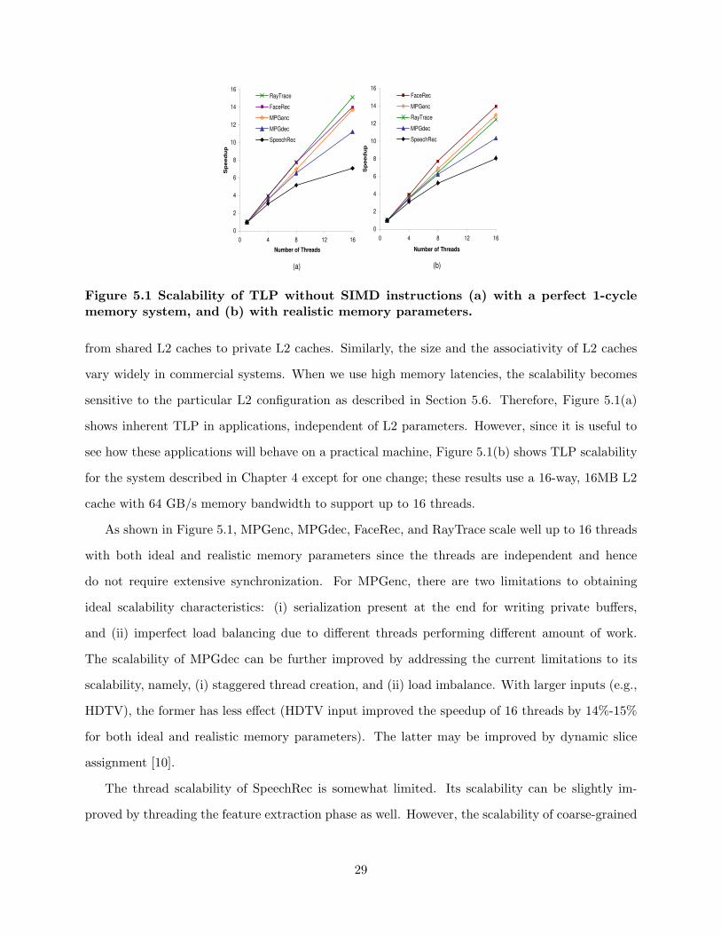
Figure 5.1(a) and (b) show the speedup achieved with multiple threads on AlpSim with a 1 cycle
ideal memory system and a nonideal memory system, respectively. The threads do not use any
DLP instructions. The ideal memory system results are obtained with perfect 1 cycle L1 caches to
study the TLP scalability independent of the memory system parameters, especially those of the
L2 cache. These applications can be executed on systems with very different L2 configurations,
28
0
2
4
6
8
10
12
14
16
0 4 8 12 16
Number of Threads
Sp
eed
up
RayTrace
FaceRec
MPGenc
MPGdec
SpeechRec
0
2
4
6
8
10
12
14
16
0 4 8 12 16
Number of Threads
Sp
eed
up
FaceRec
MPGenc
RayTrace
MPGdec
SpeechRec
(a) (b)
Figure 5.1 Scalability of TLP without SIMD instructions (a) with a perfect 1-cyclememory system, and (b) with realistic memory parameters.
from shared L2 caches to private L2 caches. Similarly, the size and the associativity of L2 caches
vary widely in commercial systems. When we use high memory latencies, the scalability becomes
sensitive to the particular L2 configuration as described in Section 5.6. Therefore, Figure 5.1(a)
shows inherent TLP in applications, independent of L2 parameters. However, since it is useful to
see how these applications will behave on a practical machine, Figure 5.1(b) shows TLP scalability
for the system described in Chapter 4 except for one change; these results use a 16-way, 16MB L2
cache with 64 GB/s memory bandwidth to support up to 16 threads.
As shown in Figure 5.1, MPGenc, MPGdec, FaceRec, and RayTrace scale well up to 16 threads
with both ideal and realistic memory parameters since the threads are independent and hence
do not require extensive synchronization. For MPGenc, there are two limitations to obtaining
ideal scalability characteristics: (i) serialization present at the end for writing private buffers,
and (ii) imperfect load balancing due to different threads performing different amount of work.
The scalability of MPGdec can be further improved by addressing the current limitations to its
scalability, namely, (i) staggered thread creation, and (ii) load imbalance. With larger inputs (e.g.,
HDTV), the former has less effect (HDTV input improved the speedup of 16 threads by 14%-15%
for both ideal and realistic memory parameters). The latter may be improved by dynamic slice
assignment [10].
The thread scalability of SpeechRec is somewhat limited. Its scalability can be slightly im-
proved by threading the feature extraction phase as well. However, the scalability of coarse-grained
29

2.8
2.0
1.31.1
6.0
3.0
1.8 1.7
0
1
2
3
4
5
6
MPGenc MPGdec SpeechRec FaceRec
Sp
eed
up
SSE2 ALP SIMD
Figure 5.2 Speedup with SSE2 and ALP SIMD.
threads in SpeechRec is mainly limited by the fine grain synchronization (locking) used in the
search phase [16]. However, we found that larger dictionaries increase the thread scalability. Note
that multithreaded versions of SpeechRec achieve slightly better speedups with realistic memory
parameters. In that case, the execution time of the single thread version is dominated by the
time stalled for memory. The multithreaded version can reduce that stall time considerably due to
memory parallelism offered by multiple threads. However, with ideal memory parameters, the mul-
tithreaded version cannot reduce the memory access time any further. Therefore, synchronization
has a larger negative effect on the multithreaded versions with ideal memory parameters.
5.2 DLP - SIMD
This section reports the benefits of SIMD for our applications (all except RayTrace, which does
not show DLP).
Figure 5.2 gives the speedups achieved with SSE2 (on P4Sys) and ALP SIMD (on AlpSim) over
the original non-SIMD single-threaded application. The results with SSE2 show the speedups
achievable on existing general-purpose processors. The results with ALP SIMD indicate the
speedups possible with a more general form of SIMD on a simulated 4-GHz processor. Over-
all, our applications (except RayTrace) achieve significant speedups with ALP SIMD and modest
to significant speedups with SSE2.
For all applications, the speedups with ALP SIMD are higher than the speedups with SSE2
due to several reasons. First, the latency of most SIMD instructions on AlpSim is 1 cycle whereas
30

all SSE2 instructions have multicycle latencies. Further, the 128b SSE2 is implemented as two 64b
operations on Pentium processors essentially halving the throughput. Specifically, FaceRec fails to
achieve any significant speedup with SSE2 due to the lack of true 128b units because FaceRec uses
double precision 64b operations. Second, the simulated processor has 4 SIMD units and a different
pipeline and hardware resources. Third, AlpSim supports SIMD opcodes that are more advanced
than those in SSE2. For instance, horizontal subword reductions are available in AlpSim but not
in SSE2 (although they are available with SSE31).
5.2.1 SIMD speedups of individual phases with SSE2
All phases and subphases of an application do not see the same level of performance improvement
with SIMD support. Therefore, it is important to understand which parts of an application are
more amenable to SIMD and which parts are not. Although some phases can show very high
speedups, according to Amdahl’s law, the overall speedup of the application is limited by phases
with small or no speedups.
Table 5.1 shows the percentage of execution time and the SSE2 speedup of each phase in each
application on P4Sys. The total SSE2 speedup for each application is also given. These results show
which phases of the applications are more amenable to SIMD. The data for RayTrace is omitted
since it does not have DLP instructions or multiple major phases. Note that the sampling error for
small phases is more significant than for larger phases; small phases (i.e., phases with non-SSE2
execution time less than 2% or aggregates of such small phases) where the speedup cannot be
measured reliably are marked as N/A in Table 5.1. It should also be noted that the phases in an
application cannot be completely separated from the adjacent phases of the same application when
run on an out-of-order processor where instructions from multiple phases can overlap. Further, the
effects produced by one phase (e.g., branch histories, cache data) can affect other phases. As a
result, Table 5.1 shows small slowdowns for some phases.
MPGenc and MPGdec see good overall speedups with SSE2. All phases of MPGenc and all but
the VLD phase in MPGdec achieve speedups with SSE2. IDCT of MPGdec and DCT/IDCT
1We did not use SSE3 for our applications since it is fairly new and most existing systems do not support it.
31

Table 5.1 Percentage execution time and SSE2 speedup for major phases of eachapplication (except for RayTrace) on P4Sys. Small phases (i.e., phases with non-SSE2execution time less than 2% or aggregates of such small phases) where the speedupcannot be measured reliably are marked as N/A.
no-SSE2 with SSE2% ExTime % ExTime Speedup
MPGencMotion Estimation 64.3 66.3 2.69DCT/IDCT 9.6 6.3 4.24Form predictions 5.6 11.9 1.3Quant/IQuant 18.8 9.2 5.69VLC 1.3 3.8 N/AOther 0.4 2.5 N/A
Total 100.0 100.0 2.78
MPGdecIDCT 36.6 13.8 5.38Motion Compensation- Saturate 8.3 10.4 1.61- Add Block 9.3 5.7 3.3- Form predictions 21.5 20.4 2.14- Clear Block 2.8 3.9 1.44VLD 20.3 43.3 0.95Other 1.3 2.4 N/A
Total 100 100 2.03
SpeechRecFeature Extraction 1.6 2.1 0.97Gaussian Scoring- Vector Quantization 35.4 26.5 1.73- Short-list Generation 10.5 13.7 0.99- Gaussian Eval 35.7 34.3 1.34- Others 7.4 10.8 N/ASearch 7.7 10.5 0.94Other 1.7 2.1 N/A
Total 100.0 100.0 1.29
FaceRecSubspace projection 88.0 88.8 1.11- Transform 87.3 87.4 1.12Distance calculation 7.4 5.7 1.47Other 5.3 6.9 N/A
Total 100.0 100.0 1.12
phases of MPGenc achieve excellent speedups due to the use of optimized SSE2 code for these
phases.
The motion estimation phase of MPGenc achieves very good speedups with SSE2 due to the
use of byte operations and the elimination of data-dependent branches using PSAD (packed sum
of absolute difference) instructions. Similarly, quantization achieves excellent speedups due to the
elimination of branches by using PMAX and PMIN instructions to truncate.
In MPGdec, subphases of motion compensation phase like saturate, add block, and form pre-
32

Figure 5.3 Speedups of VoS and SVector over SIMD.
diction achieve good speedups with SSE2 since they contain straightforward DLP loops with (sat-
urated) additions and subtractions. But VLD which is a significant portion of the total application
does not see any speedup resulting in a lower overall speedup than MPGenc.
SpeechRec achieves reasonable speedup with SSE2 (due to its use of 32b single precision floats,
the peak possible speedup is roughly 2X on Gaussian scoring). As expected, SIMD instructions
lead to significant speedups in the two most dominant subphases of the Gaussian scoring phase.
However, the overall speedup is limited by phases without DLP.
FaceRec fails to achieve significant speedups with SSE2 due to FaceRec’s use of double precision
64b operations as described above. However, it succeeds in recording a small overall speedup due
to the elimination of overhead instructions.
5.3 DLP - VoS and SVectors
This section compares the different DLP mechanisms—SIMD, VoS, and SVectors/SStreams. For
SIMD, this section uses ALP SIMD. RayTrace will not be discussed because it does not show DLP.
Figure 5.3 presents the speedups over SIMD achieved by SVectors and VoS. Overall, both
SVector and VoS are able to outperform SIMD in all of ALPBench’s DLP applications. That shows
both vector extensions to SIMD are beneficial and able to exploit more DLP than SIMD. Further,
33
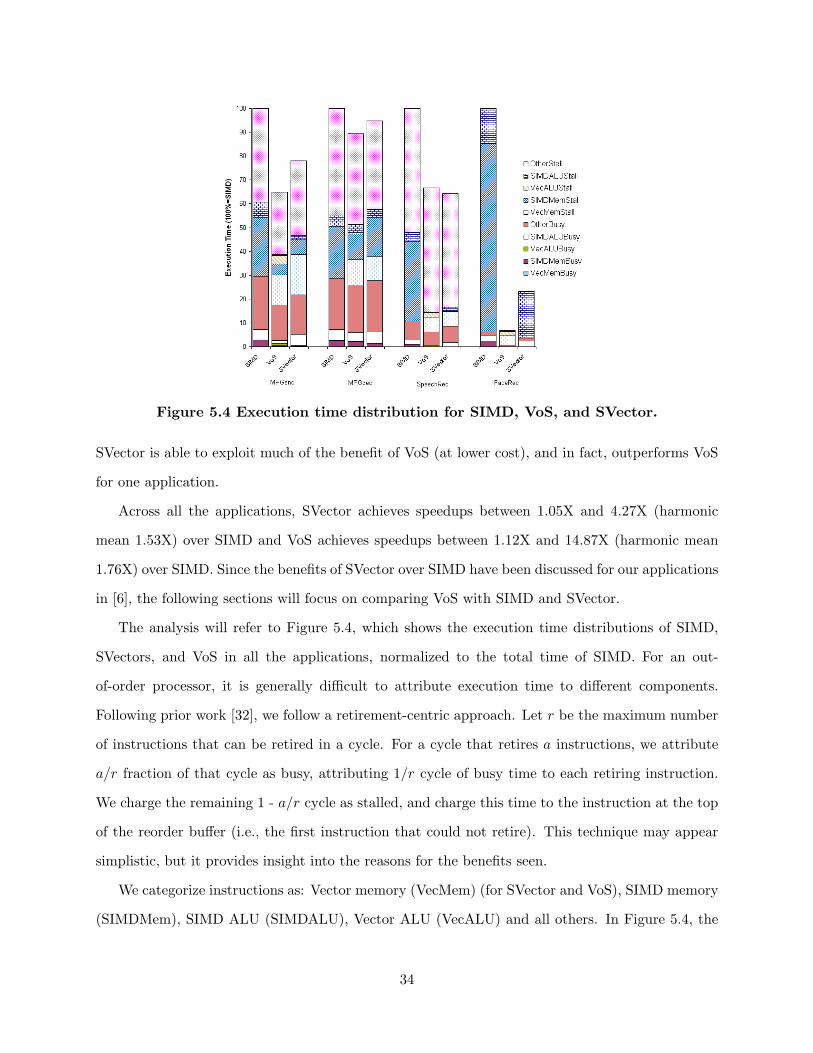
Figure 5.4 Execution time distribution for SIMD, VoS, and SVector.
SVector is able to exploit much of the benefit of VoS (at lower cost), and in fact, outperforms VoS
for one application.
Across all the applications, SVector achieves speedups between 1.05X and 4.27X (harmonic
mean 1.53X) over SIMD and VoS achieves speedups between 1.12X and 14.87X (harmonic mean
1.76X) over SIMD. Since the benefits of SVector over SIMD have been discussed for our applications
in [6], the following sections will focus on comparing VoS with SIMD and SVector.
The analysis will refer to Figure 5.4, which shows the execution time distributions of SIMD,
SVectors, and VoS in all the applications, normalized to the total time of SIMD. For an out-
of-order processor, it is generally difficult to attribute execution time to different components.
Following prior work [32], we follow a retirement-centric approach. Let r be the maximum number
of instructions that can be retired in a cycle. For a cycle that retires a instructions, we attribute
a/r fraction of that cycle as busy, attributing 1/r cycle of busy time to each retiring instruction.
We charge the remaining 1 - a/r cycle as stalled, and charge this time to the instruction at the top
of the reorder buffer (i.e., the first instruction that could not retire). This technique may appear
simplistic, but it provides insight into the reasons for the benefits seen.
We categorize instructions as: Vector memory (VecMem) (for SVector and VoS), SIMD memory
(SIMDMem), SIMD ALU (SIMDALU), Vector ALU (VecALU) and all others. In Figure 5.4, the
34

lower part of the bars shows the busy time divided into the above categories, while the upper part
shows the stall components. The busy time for a category is directly proportional to the number
of instructions retired in that category. We also note that the “other” category includes overhead
instructions for address generation for SIMDMem instructions and SIMD loop branches; therefore,
the time spent in the DLP part of the application exceeds that shown by the SIMD (and vector)
category of instructions.
5.3.1 VoS versus SIMD
This section compares VoS with SIMD.
Reduction in busy time: The reduction of busy time is defined as the decrease from SIMD’s
(SIMDMemBusy +SIMDALUBusy +OtherBusy) to VoS’s (V ecMemBusy +V ecALUBusy +
OtherBusy). In all of the applications, the busy times are reduced because of the instruction
count reduction from vectorizing SIMD loops with VoS instructions. As VoS memory and compute
instructions replace loops of SIMD memory and compute instructions, respectively, the instruction
count is drastically reduced. Further, since the overhead instructions (e.g., address calculations,
loop counting, etc.) are eliminated in the VoS code, shorter OtherBusy time results.
All applications except MPGdec have noticeable reductions. Reduction is small in MPGdec
because IDCT could not be vectorized (Section 3.1), which is a significant portion of MPGdec.
The small reduction comes from the use of VoS instructions in motion compensation.
On the other hand, FaceRec has the most reduction (percentage-wise) mainly because of the
use of long vectors. As the maximum vector length of 64 is used in FaceRec, each VoS instruction
represents 64 SIMD instructions and the number of VoS instructions is roughly 1/64 of the number
of SIMD instructions.
The busy time reductions are noticeable (about 42%) in both MPGenc and SpeechRec. Never-
theless, the reduction is partly offset because VoS’s vertical reduction loops used in both applications
introduce other new overhead instructions.
Reduction in DLP Mem stall: This is defined as the reduction from SIMD’s SIMDMemStall
35

to VoS’s (SIMDMemStall + V ecMemStall). In SIMD, the instructions (memory and compute)
in a SIMD loop are queued in the reorder buffer (ROB) and retire from the buffer in program
order after completion. The number of SIMD memory instructions that can be issued in parallel
is therefore limited by the size of the ROB and the distribution of memory instructions in the
SIMD loops. On the other hand, a vector memory instruction gathers up to 64 SIMD memory
accesses but only takes up one entry in the ROB. As a result, VoS memory instructions allow much
more memory-level parallelism to be exploited when compared with SIMD and hence cause fewer
memory stalls. This is particularly beneficial for applications with high L2 miss rates and systems
with long memory latencies.
For our application suite, FaceRec and SpeechRec have the largest L2 working sets and miss
rates (Section 5.6.1) and so see the largest reductions in memory stall time. MPGenc and MPGdec,
on the other hand, have high L1 and L2 hit rates and so see modest benefits.
Reduction in DLP ALU stall: This is classified as the difference between SIMD’s SIMDALUStall
and VoS’s (SIMDALUStall + V ecALUStall). Overall, VoS results in a reduction in DLP ALU
stalls for the following reasons: In SIMD, the number of SIMD compute instructions that can be
issued in parallel is limited (1) by the size of the reorder buffer (ROB) and the distribution of
independent compute instructions in the SIMD loops and (2) by the availability of the functional
units (2 multipliers and 3 adders). In VoS, on the other hand, (1) a vector instruction only takes
up one ROB entry while expressing up to 64 indepdent SIMD operations, making the ROB size
less of a factor and (2) VoS supports more functional units (8 multipliers and 8 adders2) than
SIMD. However, VoS does not completely eliminate DLP ALU stall time for the following three
key reasons: (1) As described in Section 2.3.2.2, VoS does not chain a memory instruction with
a dependent compute instruction. Hence, all vector load dependent vector compute instructions
need to wait for the whole vector to be loaded from the memory before executing. (2) The vertical
reductions of VoS are done after the main computation (versus SIMD’s vertical reductions that
overlap with the main computation in the SIMD loop) and the dependency between instructions
from different reduction loop iterations are exposed as stall time. (3) For MPGdec, the IDCT loop
2The functional units are arranged in four lanes and appear as two resources (Section 2.3.2). Each resourcecontains 4 multipliers and 4 adders.
36

does not use VoS instructions and so shows negligible reductions.
Reduction in other stall: As the VoS programming model eliminates the need for SIMD loops,
the reduction in other stalls comes from a reduction in the overhead instructions in the SIMD
loops. However, this reduction is offset by the overhead instructions introduced in VoS’s reduction
operations. This effect is most noticeable in SpeechRec because all of SpeechRec’s VoS-enhanced
code involves frequent reductions of short vectors. On the other hand, while MPGenc also in-
volves frequent reductions of short vectors, the other VoS-enhanced subphases (block prediction,
quantization, and inverse quantization) help alleviate this negative effect.
5.3.2 VoS versus SVector
This section compares VoS with SVector.
Reduction in busy time: The reduction of busy time is defined as the decrease from SVector’s
(SIMDMemBusy+V ecMemBusy+SIMDALUBusy+OtherBusy) to VoS’s (V ecMemBusy+
V ecALUBusy + OtherBusy). In all of the applications, the busy times are reduced because of
the instruction count reduction from vectorizing SIMD loops with VoS instructions. As VoS com-
pute instructions replace loops of SVector’s SIMD compute instructions, the instruction count is
noticeably reduced. Further, since the overhead instructions for loop counting are eliminated in the
VoS code, shorter OtherBusy time results. FaceRec has the largest percentage decrease because
the vector instructions operate on the maximum vector length and each is equivalent to 64 SIMD
operations. On the other hand, MPGdec sees the smallest decrease since VoS is not applicable to
the IDCT code which is a major part in the application. Nevertheless, vectorizing motion compen-
sation brings a slight reduction from SVector.
DLP Mem stall: The difference between the (SIMDMemStall+V ecMemStall) of SVector and
VoS is small in MPGdec and SpeechRec. This is because both VoS and SVector use vector memory
instructions at the same DLP regions.
In FaceRec, streaming instructions are used in SVector and result in almost no V ecMemStall.
37

This is because SVector’s stream load instruction is retired before the loads complete, at the cost
of a slightly more complex exception model [6]. However, the dependent SIMD instructions are
stalled if the data is not available. Hence, the original memory stall becomes an ALU stall. This
effect can be seen by comparing the SIMDALUStall of SVector and SIMD. Had FaceRec been
enhanced with SVectors (vs. SStreams) instructions only, there would be a noticeable amount of
V ecMemStall in the SVector case.
DLP ALU stall: When comparing the (V ecALUStall + SIMDALUStall) of VoS and SVector,
SVector has the smaller stall time except for FaceRec. This is attributed to SVector’s ability to
chain (i.e., forward) a memory instruction with a dependent compute instruction. In SVector, the
scheduler always checks the availability of the source SVR elements before issuing a SIMD compute
instruction. Therefore, instructions that are dependent on vector loads can execute as soon as
the corresponding vector elements have arrived and need not to wait for the whole vector to be
fetched. On the other hand, the lack of memory-compute chaining support in VoS mentioned in
Section 5.3.1 (Reduction in DLP SIMD stall) causes compute instructions’ latencies to be exposed
as stall time. This difference gives SVector the advantage and thus SVector has fewer stalls than
VoS in MPGenc, MPGdec, and SpeechRec. For FaceRec, due to the retirement model of SStreams
described above, SVector suffers a significant amount of (perceived) ALU stall.
Furthermore, part of VoS’s ALU stalls in MPGenc, SpeechRec, and FaceRec occur becauase
VoS’s tree reductions are carried out separately after the main computation. Consequently, the
tree reductions cannot be overlapped by other computations and result in stalls.
Other stall: MPGenc, SpeechRec, and FaceRec all contain reduction operations. In VoS, reduc-
tion operations introduce overhead instructions and can increase OtherStall. In SpeechRec and
FaceRec, since the SIMD computations that contain reduction operations are the major parts of
the applications, there is an increase in OtherStall. The amount of increase of OtherStall depends
on the vector lengths. In FaceRec, the long vectors (64 records) used in FaceRec result in relatively
less frequent reductions and thus less increase in OtherStall. In SpeechRec, on the other hand, the
short vectors (10 records) and frequent reductions cause more noticeable increase in OtherStall,
38

and this stall time is mainly responsible for VoS’s slowdown from SVector.
5.4 ILP
Table 5.2 gives instructions-per-cycle (operations per cycle) achieved on AlpSim and x86 instruc-
tions per cycle (microinstructions per cycle) achieved on P4Sys. The IPC values for AlpSim and
P4Sys cannot be directly compared because they do not use the same instruction set, processor
or memory parameters. Rather, P4Sys data represents a real 3.06 GHz system and AlpSim data
represents a simulated 4 GHz system.
Table 5.2 Instructions per cycle achieved on AlpSim and P4Sys for single-thread ap-plications. For the ALP SIMD case, the number of subword operations retired percycle is also given within square brackets. For P4Sys, x86 microinstructions per cycleis given in parenthesis.
AlpSim P4Sys (Pentium 4)
App Base SIMD Base SIMDMPGenc 1.20 1.23 [4.24] 1.45 (1.87) 0.70 (1.03)MPGdec 1.38 1.17 [3.31] 1.26 (1.73) 0.73 (1.14)RayTrace 1.33 N/A 0.48 (0.73) N/ASpeechRec 0.35 0.39 [0.67] 0.38 (0.57) 0.34 (0.45)FaceRec 0.32 0.30 [0.48] 0.51 (0.61) 0.43 (0.47)
FaceRec and SpeechRec fail to achieve large ILP due to their working sets not fitting in caches
(Section 5.6). Other applications show reasonable ILP on AlpSim. However, the SIMD versions
of MPGenc and MPGdec and the base version of RayTrace achieve lower IPC on P4Sys than on
AlpSim. Specifically for the SIMD versions of MPGenc and MPGdec, as described in Section 5.2,
the longer SSE2 latencies and the lack of true 128-bit functional units lower the IPC on P4Sys. For
RayTrace, P4Sys sees lower IPC than AlpSim due to three main reasons. First, longer FP laten-
cies and longer repetition intervals (lower throughput) of the FP units of P4 reduce performance.
Second, the smaller 8K L1 cache of P4 further reduces the performance since RayTrace achieves
lower hit rates with an 8K L1 data cache compared to a 32K L1 of AlpSim (see Figure 5.6 in Sec-
tion 5.6.1). Third, the much deeper pipeline of P4 reduces performance since branch misprediction
rate is somewhat high (4%) and 10% of all instructions are branches. However, P4Sys sees higher
IPC for some applications due its lower frequency, L2 hardware prefetcher, and differences in the
39
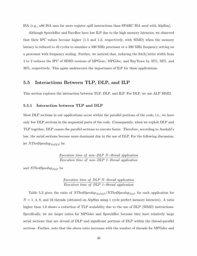
ISA (e.g., x86 ISA uses far more register spill instructions than SPARC ISA used with AlpSim).
Although SpeechRec and FaceRec have low ILP due to the high memory latencies, we observed
that their IPC values become higher (1.5 and 1.3, respectively, with SIMD) when the memory
latency is reduced to 42 cycles to simulate a 500 MHz processor or a 500 MHz frequency setting on
a processor with frequency scaling. Further, we noticed that, reducing the fetch/retire width from
4 to 2 reduces the IPC of SIMD versions of MPGenc, MPGdec, and RayTrace by 35%, 33%, and
38%, respectively. This again underscores the importance of ILP for these applications.
5.5 Interactions Between TLP, DLP, and ILP
This section explores the interaction between TLP, DLP, and ILP. For DLP, we use ALP SIMD.
5.5.1 Interaction between TLP and DLP
Most DLP sections in our applications occur within the parallel portions of the code; i.e., we have
only few DLP sections in the sequential parts of the code. Consequently, when we exploit DLP and
TLP together, DLP causes the parallel sections to execute faster. Therefore, according to Amdahl’s
law, the serial sections become more dominant due to the use of DLP. For the following discussion,
let NThrdSpeedupNoDLP be
Execution time of non−DLP N−thread application
Execution time of non−DLP 1−thread application
and NThrdSpeedupDLP be
Execution time of DLP N−thread application
Execution time of DLP 1−thread application
Table 5.3 gives the ratio of NThrdSpeedupNoDLP/NThrdSpeedupDLP for each application for
N = 1, 4, 8, and 16 threads (obtained on AlpSim using 1 cycle perfect memory latencies). A ratio
higher than 1.0 shows a reduction of TLP scalability due to the use of DLP (SIMD) instructions.
Specifically, we see larger ratios for MPGdec and SpeechRec because they have relatively large
serial sections that are devoid of DLP and significant portions of DLP within the thread-parallel
sections. Further, note that the above ratio increases with the number of threads for MPGdec and
40
SpeechRec limiting their TLP scalability in the presence of DLP. This can have a significant impact
on the TLP scalability of emerging multicore/multithreaded commercial processors that already
support SIMD instructions. The above ratio stays close to 1 for MPGenc and FaceRec since they
do not have large serial sections.
Table 5.3 Ratio NThrdSpeedupNoDLP / NThrdSpeedupDLP for 1, 4, 8, and 16 threads for allapplications with DLP.
App 1T 4T 8T 16T
MPGenc 1.00 0.99 1.01 1.09MPGdec 1.00 1.12 1.27 1.55SpeechRec 1.00 1.09 1.23 1.49FaceRec 1.00 0.97 0.96 0.96
5.5.2 Interaction between DLP and ILP
Exploiting DLP in a given piece of code should theoretically reduce the amount of ILP present in
that section of code since one DLP instruction can replace multiple independent non-DLP instruc-
tions. Table 5.2 shows this decrease for all applications except MPGenc and SpeechRec with ALP
SIMD.
The exceptions occur for multiple reasons. First, on real processors, the DLP is usually ex-
ploited using separate resources. For instance, on Pentium processors and on AlpSim, the SIMD
instructions are executed in the FP pipeline. Therefore, exploiting SIMD in integer code allows the
otherwise idle FP pipeline to be utilized as well. This could increase the amount of ILP exploited
in a cycle. Second, the SIMD instructions can reduce contention to the critical processor resources
(e.g., load/store queue entries, cache ports) by combining several non-DLP instructions into one
DLP instruction. The reduced contention potentially allows more ILP to be exploited from a piece
of code. Third, SIMD code reduces the number of conditional branch instructions. This happens
mainly because SIMD reduces the number of loop iterations and the branches associated with
them. Further, some SIMD instructions like packed absolute difference, packed sum of absolute
difference (PSAD), or packed maximum and minimum can reduce data dependent branches used
in non-SIMD code.
41

MPGenc
0.5
0.6
0.7
0.8
0.9
1
1 10 100 1000 10000
Cache Size (KB)
Hit
Rate
4 Thread
1 Thread
MPGdec
0.5
0.6
0.7
0.8
0.9
1
1 10 100 1000 10000
Cache Size (KB)
Hit
Rate
4 Thread
1 Thread
RayTrace
0.5
0.6
0.7
0.8
0.9
1
1 10 100 1000 10000
Cache Size (KB)
Hit
Rate
4 Thread
1 Thread
SpeechRec
0.5
0.6
0.7
0.8
0.9
1
1 10 100 1000 10000
Cache Size (KB)
Hit
Rate
4 Thread
1 Thread
FaceRec
0.5
0.6
0.7
0.8
0.9
1
1 10 100 1000 10000
Cache Size (KB)
Hit
Rate
4 Thread
1 Thread
Figure 5.5 L2 cache hit rates. The rates are with SIMD for all applications exceptRayTrace, for which it is without SIMD.
5.5.3 Interaction between TLP and ILP
The interaction between TLP and ILP is well known. On practical CMP systems, TLP can affect
the amount of ILP available to a particular thread. The behavior of the caches could change due
to the presence of multiple threads and could affect the ILP of each thread. As discussed later
(Figure 5.5 and Section 5.6), it is possible to have both positive and negative cache effects due
to multiple threads. For instance, false sharing in caches could reduce the ILP whereas sharing
of read-only data (or instructions) could increase the ILP of each thread. Table 5.4 gives the
percentage reduction of per thread IPC in a 16-thread CMP with respect to the IPC of a single-
thread processor. The IPC does not include the effect of synchronization instructions. We see that
multiple threads cause a small to modest reduction in per-thread IPC due to the effects discussed
above. This reduction is smallest in FaceRec due to some constructive data sharing among threads
in the L2 cache (see Section 5.6.1).
42
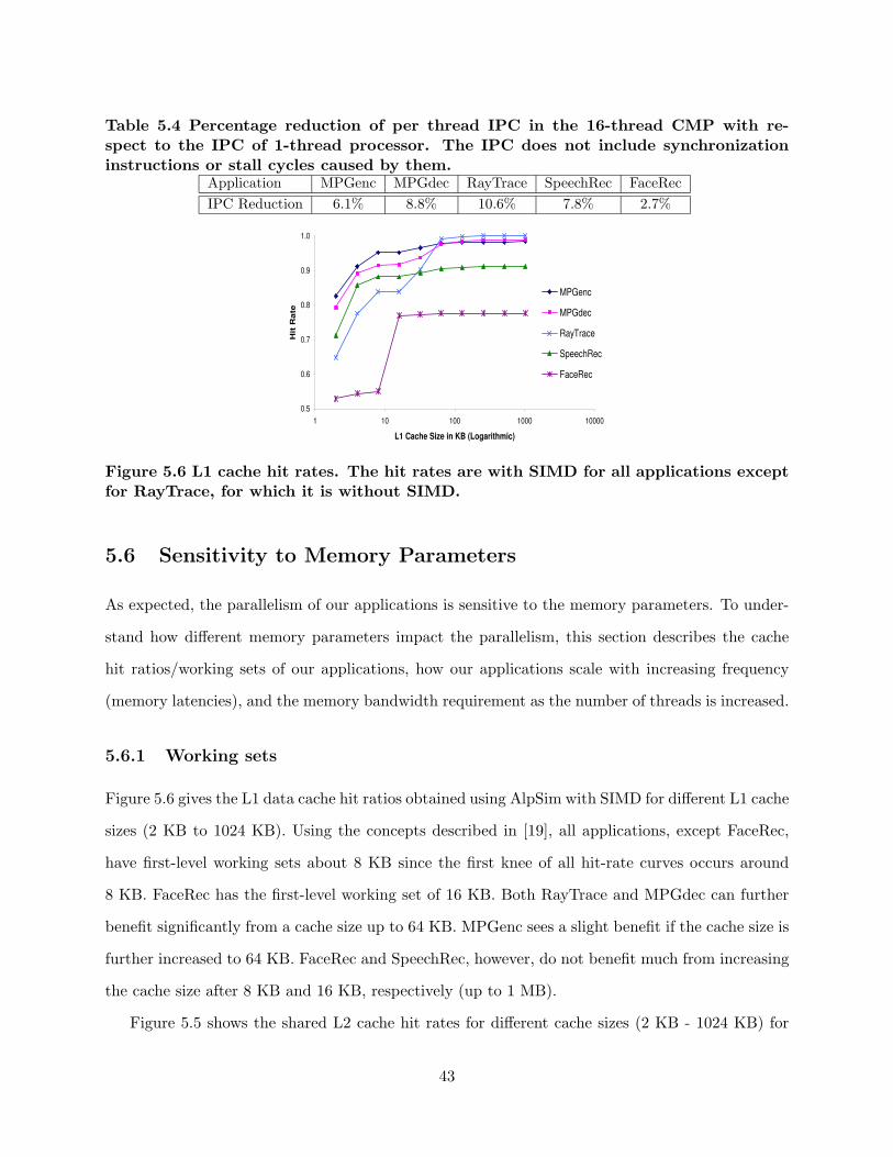
Table 5.4 Percentage reduction of per thread IPC in the 16-thread CMP with re-spect to the IPC of 1-thread processor. The IPC does not include synchronizationinstructions or stall cycles caused by them.
Application MPGenc MPGdec RayTrace SpeechRec FaceRec
IPC Reduction 6.1% 8.8% 10.6% 7.8% 2.7%
0.5
0.6
0.7
0.8
0.9
1.0
1 10 100 1000 10000
L1 Cache Size in KB (Logarithmic)
Hit
Ra
teMPGenc
MPGdec
RayTrace
SpeechRec
FaceRec
Figure 5.6 L1 cache hit rates. The hit rates are with SIMD for all applications exceptfor RayTrace, for which it is without SIMD.
5.6 Sensitivity to Memory Parameters
As expected, the parallelism of our applications is sensitive to the memory parameters. To under-
stand how different memory parameters impact the parallelism, this section describes the cache
hit ratios/working sets of our applications, how our applications scale with increasing frequency
(memory latencies), and the memory bandwidth requirement as the number of threads is increased.
5.6.1 Working sets
Figure 5.6 gives the L1 data cache hit ratios obtained using AlpSim with SIMD for different L1 cache
sizes (2 KB to 1024 KB). Using the concepts described in [19], all applications, except FaceRec,
have first-level working sets about 8 KB since the first knee of all hit-rate curves occurs around
8 KB. FaceRec has the first-level working set of 16 KB. Both RayTrace and MPGdec can further
benefit significantly from a cache size up to 64 KB. MPGenc sees a slight benefit if the cache size is
further increased to 64 KB. FaceRec and SpeechRec, however, do not benefit much from increasing
the cache size after 8 KB and 16 KB, respectively (up to 1 MB).
Figure 5.5 shows the shared L2 cache hit rates for different cache sizes (2 KB - 1024 KB) for
43

both single-thread and four-thread versions of each application with SIMD. The L1 caches were
disabled for this experiment to study the effect of data sharing between multiple threads in L2. If
the threads share a significant portion of data and the single thread version achieves a given hit
rate with x KB, the four-thread version should be able to achieve the same or a better hit rate
with 4x KB of cache. Based on the data of Figure 5.5, we can see that only threads in FaceRec
share a significant portion of data since the four-thread version achieves better hit rates than the
single-thread version for a given cache size. This is because the threads in FaceRec share parts of
the large subspace matrix (database). Since we partition data among threads for all applications,
the threads in the other applications do not exhibit constructive sharing. Even FaceRec, which
exhibits some data sharing, does not share all the data in L2 since a significant portion of its
memory accesses still have to go to memory.
To summarize, first we see that three of our applications have very good cache hit rates whereas
two have low hit rates. Low cache hit rates reduce ILP when memory latencies are high. We also see
that increasing TLP demands larger caches to accommodate the working sets of our applications
since threads do not share much data.
5.6.2 Sensitivity to memory latency or processor frequency
Figure 5.7 shows the speedup achieved by the base (non-SIMD) and SIMD versions of each single-
thread application on AlpSim when the processor frequency is scaled from 4 GHz to 500 MHz.
For RayTrace, the results for non-SIMD single-thread version are shown. The time to access the
memory (and the memory bus) is decreased linearly from 240 cycles (at 4 GHz) to 30 cycles (at 500
MHz) (i.e., the L2 miss latency is the memory/bus access time plus 16 cycles for all frequencies).
The other parameters given in Table 4.1 are not changed. Specifically, the parameters used at 4
GHz are identical to those given in Table 4.1. Speedups reported for non-SIMD (SIMD) are with
respect to the non-SIMD (SIMD) single thread version of the application running at the lowest
frequency (500 MHz). Such frequency scaling data is important since many systems, especially
mobile systems running these media applications, run at lower frequencies. Further, many such
systems employ dynamic frequency scaling to run at lower frequencies than the maximum frequency
supported by the processor to reduce power and energy consumption. The following describes how
44

MPGenc
0
1
2
3
4
5
6
7
8
0 1000 2000 3000 4000
Frequency (MHz)
Sp
eed
up
Base
SIMD
MPGdec
0
1
2
3
4
5
6
7
8
0 1000 2000 3000 4000
Frequency (MHz)
Sp
eed
up
Base
SIMD
SpeechRec
0
1
2
3
0 1000 2000 3000 4000
Frequency (MHz)
Sp
eed
up
SIMD
Base
FaceRec
0
1
2
3
0 1000 2000 3000 4000
Frequency (MHz)
Sp
eed
up
Base
SIMD
RayTrace
0
2
4
6
8
10
0 1000 2000 3000 4000
Frequency (MHz)
Sp
eed
up
Base
Figure 5.7 Frequency Scalability. The SIMD data are with ALP SIMD for all appli-cations.
each application scales when the frequency is increased from the lowest (500 MHz) to the highest
(4 GHz).
Figure 5.7 shows that the base cases of RayTrace, MPGenc and MPGdec scale well with in-
creasing frequency since most of their working sets fit in the caches. The base cases of FaceRec
and SpeechRec show poor scalability after 1 or 2 GHz. This is mainly due to their larger working
sets not fitting in caches (Figure 5.6).
Two factors affect the relative scalability between SIMD and non-SIMD versions of the same
application. On the one hand, the SIMD version has a lower computation to memory ratio than
the base case and hence is more sensitive to longer memory latencies. This is because the SIMD
case reduces loop overhead and address calculation overhead instructions, which are compute in-
structions. This effect causes the SIMD versions of MPGenc, MPGdec, and FaceRec to show lower
scalability. The effect is more prominent in MPGenc due to its use of small subwords; in that
case, SIMD can reduce the loop iteration and overhead significantly. On the other hand, the SIMD
version exposes more memory level parallelism to the out-of-order core – since the SIMD loops use
45

fewer instructions per loop, the instruction window can contain a larger number of load instructions
than possible in the non-SIMD case. This effect gives the SIMD version better scalability when
the application has a significant L2 miss rate. Specifically, SpeechRec benefits from this effect.
Although, the SIMD version of FaceRec should benefit from the same effect since it has high L2
miss rates, the increase in memory level parallelism for the SIMD version of FaceRec is low due to
its use of double precision operations. That is, the number of additional loop iterations we can fit
in the instruction window is not large as that of SpeechRec.
To summarize, three out of five of our applications scale well with frequency. We see that higher
memory latencies affect applications with and without SIMD differently. SIMD versions of all our
applications except SpeechRec show somewhat poorer scalability with increasing frequency than
their non-SIMD counterparts.
5.6.3 Memory bandwidth
Figure 5.8 shows how memory bandwidth demand increases for each application (non-SIMD) with
the number of threads at 4 GHz. The results were obtained on AlpSim without ALP SIMD using
the same parameters used for obtaining Figure 5.1(b). MPGenc, MPGdec, and RayTrace have
relatively low bandwidth requirements since they have smaller working sets. However, FaceRec
and SpeechRec demand much larger memory bandwidth since their working sets do not fit in the
L2 cache. The increase in bandwidth generally follows the TLP speedup of applications, except for
RayTrace where the 16-thread version requires less memory bandwidth than the 8-thread version.
This is because the L1 hit ratio of the 16-thread case is far better than that for the 8-thread case due
to the working set getting divided into 16 in the 16-thread case. For all applications that have DLP,
SIMD versions will demand more bandwidth since they execute faster. These results show that
the bandwidth of MPGenc, MPGdec, and RayTrace can be fulfilled by existing memory systems
(assuming a maximum of 8.5 GB/s memory bandwidth on current personal computers with DDR2
memory). However, for SpeechRec and FaceRec, CMP systems that support 8 or more threads
will have to support a higher memory bandwidth than supported today on many general-purpose
systems [33].
46

0.2
0.2
0.2
2.1 2.5
0.6
0.7 0.9
6.4
9.1
1.2 1.4 1.6
11
.3
16
.0
2.1 2.2
1.5
27
.9
16
.9
0
5
10
15
20
25
MPGenc MPGdec RayTrace SpeechRec FaceRec
Mem
ory
Ban
dw
idth
(G
B/s
)
1 Thread 4 Thread 8 Thread 16 Thread
Figure 5.8 Memory bandwidth (in GB/s) at 4 GHz without SIMD.
Table 5.5 Application-level real-time performance obtained by single threaded versionsof our applications on a 3.06-GHz Pentium-4 processor with SSE2.
Application Performance
MPGenc 21.8 fps (704x480 DVD resolution)MPGdec 166.3 fps (704x480 DVD resolution)RayTrace 0.75 fps (512x512 resolution)SpeechRec 9.0 words/sec.FaceRec 152.1 130x150 images/sec.
5.7 Application-Level Real-Time Performance
Table 5.5 shows the application-level real-time performance results for each application on P4Sys
(Section 4). The results are for single-threaded applications with SSE2 (except for RayTrace). The
approximate performance for systems with a higher number of threads and lower frequencies can
be derived using the thread/frequency scaling results presented earlier. MPGdec already achieves
the required real-time performance on current systems. The performance of RayTrace is far from
real-time. Although MPGenc comes close to the required real-time performance of 30 frames
per second, larger inputs (e.g., HDTV) will demand much higher performance. Similarly, although
SpeechRec and FaceRec achieve reasonable performance with the given small input sets, much larger
inputs anticipated in the future (e.g., much larger vocabularies and dictionaries for SpeechRec,
higher resolution image/face recognition used with personal/database search, and much larger
image databases) will demand much higher processing capabilities.
47

CHAPTER 6
RELATED WORK
There have been many studies that characterize the individual applications used in ALPBench.
Several papers characterize MPEG-2. Chen et al. [9] and Holliman and Chen [10] characterize
various phases of MPGdec on a real system and discuss and evaluate slice assignment policies, and
data vs. functional partitioning for parallelization. However, they do not perform a thread-scaling
or a frequency scaling study. We also modified MPEG encoder to use an intelligent motion search
algorithm and to use an optimized algorithm for discrete cosine transform. Iwata and Olukotun [11]
propose a number of coarse-grained parallel implementations of MPEG-2 decoding and encoding.
They evaluate the performance of these implementations on a multiprocessor, compare the perfor-
mance against a single and wide issue superscalar processor, and report results with multithreading
for four and eight processors. They also find that thread scalability of MPGenc is better than that
for MPGdec. However, they report eight thread results only with a single issue processor. We
do the TLP scalability study up to 16 threads using the same processor configuration. They also
report 50% speedup with MIPS based SIMD instructions for MPGdec. We report SSE2 speedups
for both MPGenc and MPGdec; we are able to achieve much higher speedups (2X) with SSE2 for
MPGdec. We also perform a frequency scalability study.
Turk and Pentland [34] discuss the theoretical underpinnings of the face recognition algorithms
and Beveridge et al. [35] describe the CSU face identification software used with this study. Mathew
et al. [17] characterize the features of Eigenface face recognition algorithm used in this study.
They characterize the architectural features such as cache hit rates, IPC on several embedded
architectures. In addition to these characterization, we analyze TLP and DLP in this application.
Vorbruggen [36] describes a similar face recognition algorithm used with SPEC CPU2000 but does
48

perform an evaluation.
Ravishankar [37] describes the algorithms, data structures, inputs/outputs of Sphinx 3.3 used
with this study. Mathew et al. [14] provide a detailed analysis of CMU’s Sphinx speech recognizer;
they identify the three distinct processing phases (Section 3.5), and quantify the architectural
requirements for each phase. They also describe the large memory footprint and find the Gaussian
and search phases to be the dominant ones. They also developed a parallel version of Sphinx
that runs three major phases (i.e., feature recognition, Gaussian scoring, and search) using three
threads and report a 1.67 speedup. Instead of this type of functional partitioning, we parallelize
Sphinx3.3 using data partitioning (i.e., phases are divided into N symmetric threads). This method
gives better speedups and is more scalable. They also develop a special-purpose accelerator for the
dominant Gaussian scoring phase. The accelerator consists of specialized multipliers and adders to
perform the specific multiply accumulate operation done in the inner loop of Gaussian scoring. To
overcome the latency of FP multiply accumulate operations, they pipeline multiple independent
iterations. Instead of using a separate coprocessor, we use the SIMD units to exploit the DLP in
the Gaussian scoring phase.
Baugh et al. characterize and parallelize Sphinx2 [38].1 They divide Sphinx into multiple phases
and use work queues in between phases. Then they use asymmetric threads to execute each phase.
They also investigate using symmetric threads within each phase. In contrast, we use symmetric
threads that span both Gaussian scoring and search phases and do not use work queues. They
report speedups up to 2.7X using both asymmetric and symmetric threads (a total of 6 threads).
They also show preliminary results where they achieve speedups up to 6.8X with 10 threads. They
do not investigate exploiting DLP in this study.
Krishna et al. [15] analyze parameters affecting the performance of Sphinx2 speech recognition
software with special emphasis on the memory system. They also find poor cache performance
(Figure 5.6), poor memory reference predictability, and potential for using multiple threads albeit
with higher demands on the memory system. Based on the insights from that work, they propose
architectural SMT techniques to exploit the TLP in Sphinx [16]. They develop an architecture with
multiple speech processing elements that are capable of generating their own threads and report
1Sphinx2 has somewhat different Gaussian models than those used in Sphinx3.3 [16].
49

good speedups (e.g., approximately 12X speedup with 16 speech processing elements and 4 thread
contexts per processing element). They also perform partitioning of search tree nodes; for thread
creation and synchronization, they use a fork/join model with a special barrier instruction (called
EPOCH) and locks. We use a similar approach to exploit TLP but also investigate DLP.
Woo et al. [19] present a characterization of a different version of RayTrace with other appli-
cations introduced with the SPLASH-2 benchmark. They also report working set characteristics
similar to those reported here and also report good TLP scalability. However, they do not study
the scalability of RayTrace with frequency. Nguyen et al. [18] also characterize RayTrace provided
with the SPLASH as a part of their work in evaluating multi-processor scheduling policies. They
also study the TLP scalability and identify the sources of speedup loss. However, they do not study
working sets or frequency scalability of this application.
In addition to the above studies that focus on the individual applications, there have been several
multimedia benchmark suites that target applications included in ALPBench and report their
characteristics. These include MediaBench [20], Berkeley multimedia workload [13], MiBench [21]
and EEMBC [22]. All these suites include MPEG encoder and decoder. Additionally, MiBench
includes the Sphinx2 speech recognizer, and both MediaBench and Berkeley multimedia workload
contain the RASTA speech recognizer. Berkeley multimedia workload also includes the POVray3
ray tracer as part of the suite. While all of the studies report single thread workload characteristics
of the media applications, they do not characterize DLP and TLP.
Using vector processing techniques to exploit DLP in the applications is not new. There is a
vast amount of literature on conventional vector architectures and their recent uniprocessor and
multiprocessor variations; e.g., Tarantula [25], out-of-order vectors [39], SMT Vectors [40], NEC
SX [41], Cray X1 [42], and Hitachi SR [43]. While these architectures focus on scientific and
engineering applications, VIRAM [44], CODE [45], T0 [24], and SCALE [46] are some of the
vector processors that target media applications. The MOM [47] ISA extends the subword SIMD
instruction set to exploit coarse-grained DLP in media applications. Most of these studies focus
on media kernels. Our work aims to study full media applications and also studies TLP, ILP, and
memory system related characteristics.
In summary, this work is different from each of the above works in one or more of the following
50

ways. First, we concentrate on studying the parallelism in these applications. Specifically, we
characterize ILP, TLP, and DLP and also study the interaction between two forms of parallelism.
Second, we look at the complex media applications as a benchmark suite and attempt to identify
the features and parallelism common to all of them. Third, we do this study in the context of
general-purpose CMP processors. Fourth, we include vector extensions of the subword SIMD ISA
and study the corresponding vector architectures to analyze DLP in full media applications.
51

CHAPTER 7
CONCLUSION
Complex media applications are becoming increasingly popular on general-purpose systems such as
desktops, laptops, and handheld systems. This thesis presents a suite of five such complex media
applications and characterizes the parallelism and performance of them.
Through our characterization, we find that these applications have multiple levels of parallelism
- TLP, DLP, and ILP. For TLP, we find that all our applications have coarse-grained TLP and most
of them show good thread scalability. As for DLP, we find that these applications produce good
speedups with subword SIMD. We also find that both SVector and Vector of SIMD (VoS) are able
to efficiently exploit coarse-grained DLP and achieve speedups over sub-word SIMD in ALPBench’s
DLP applications. Further, VoS is able to achieve speedups over SVector in three of the four appli-
cations. We also study the interaction between two forms of parallelism and find that exploitation
of DLP could reduce effectiveness of TLP. Further, we also study the effects of the memory sys-
tem on these applications, and report the different working sets, bandwidth requirements, and
memory latency tolerance in these applications. Our characterization of parallelism can be used
by processor/system architects and compiler writers to provide better support for complex media
applications.
52

REFERENCES
[1] K. Diefendorff and P. K. Dubey, “How multimedia workloads will change processor design,”IEEE Computer, vol. 30, pp. 43–45, Sep. 1997.
[2] R. Reddy et al., “CMU SPHINX,” 2001, http://www.speech.cs.cmu.edu/sphinx/.
[3] R. Beveridge and B. Draper, “Evaluation of face recognition algorithms,” 2003, http://www.cs.colostate.edu/evalfacerec/.
[4] J. E. Stone, “Taychon raytracer,” 2003, http://jedi.ks.uiuc.edu/~johns/raytracer/.
[5] MPEG Software Simulation Group, “MSSG MPEG2 encoder and decoder,” 1994, http://www.mpeg.org/MPEG/MSSG/.
[6] R. Sasanka, M.-L. Li, S. V. Adve, Y.-K. Chen, and E. Debes, “ALP: Efficient support forall levels of parallelism for complex media applications (submitted for publication),” Dept. ofComputer Science, University of Illinois, Tech. Rep. UIUCDCS-R-2005-2605, July 2005.
[7] J. L. Hennessy and D. A. Patterson, Computer Architecture: A Quantitative Approach. SanFrancisco, CA: Morgan Kaufmann Publishers Inc., 2002.
[8] Intel Corporation, The IA-32 Intel Architecture Optimization Reference Manual, 2004.
[9] Y.-K. Chen et al., “Media applications on hyper-threading technology,” Intel Technology Jour-nal, vol. 6, no. 1, pp. 47–57, 2002.
[10] M. Holliman and Y.-K. Chen, “MPEG decoding workload characterization,” in Proc. of Work-shop on Computer Architecture Evaluation using Commercial Workloads, 2003, pp. 23–34.
[11] E. Iwata and K. Olukotun, “Exploiting coarse-grain parallelism in the MPEG-2 algorithm,”Computer Systems Lab, Stanford University, Tech. Rep. CSL-TR-98-771, 1998.
[12] H. Kalva, A. Vetro, and H. Sun, “Performance optimization of an MPEG-2 to MPEG-4 videotranscoder,” in Proc. of SPIE Conf. on Microtechnologies for the New Millennium, VLSICircuits and Systems, 2003, pp. 341–350.
[13] N. T. Slingerland and A. J. Smith, “Design and characterization of the Berkeley multimediaworkload,” Multimedia Systems, vol. 8, no. 4, pp. 315–324, 2002.
[14] B. Mathew, A. Davis, and Z. Fang, “A low-power accelerator for the SPHINX 3 speech recogni-tion system,” in Proc. of the Intl. Conf. on Compilers, Architecture and Synthesis for EmbeddedSystems, 2003, pp. 210–219.
53

[15] R. Krishna, S. Mahlke, and T. Austin, “Insights into the memory demands of speech recog-nition algorithms,” in Proc. of the 2nd Annual Workshop on Memory Performance Issues,2002.
[16] R. Krishna, S. Mahlke, and T. Austin, “Architectural optimizations for low-power, real-timespeech recognition,” in Proc. of the Intl. Conf. on Compilers, Architectures and Synthesis forEmbedded Systems, pp. 220–231, 2003.
[17] B. Mathew, A. Davis, and R. Evans, “A characterization of visual feature recognition,” Uni-versity of Utah, Tech. Rep. UUCS-03-014, 2003.
[18] T. D. Nguyen, R. Vaswani, and J. Zahorjan, “Parallel application characterization for multi-processor scheduling policy design,” in Job Scheduling Strategies for Parallel Processing, D. G.Feitelson and L. Rudolph, Eds., Berlin, Germany: Springer-Verlag, 1996, pp. 175–199.
[19] S. C. Woo et al., “The SPLASH-2 programs: Characterization and methodological considera-tions,” in Proc. of the 22th Annual Intl. Symp. on Comp. Architecture, 1995, pp. 24–36.
[20] C. Lee, M. Potkonjak, and W. H. Mangione-Smith, “MediaBench: A tool for evaluating andsynthesizing multimedia and communicatons systems,” in Proc. of the 29th Annual Intl. Symp.on Microarchitecture, 1997, pp. 330–335.
[21] M. R. Guthaus, J. S. Ringenberg, D. Ernst, T. M. Austin, T. Mudge, and R. B. Brown,“MiBench: A free, commercially representative embedded benchmark suite,” in IEEE 4thAnnual Workshop on Workload Characterization, December 2001, pp. 3–14.
[22] EDN Embedded Microprocessor Benchmark Consortium, “The EEMBC benchmark suite,”1997, http://www.eembc.org/.
[23] G. Hinton, D. Sager, M. Upton, D. Boggs, D. Carmean, A. Kyker, and P. Roussel, “Themicroarchitecture of the Pentium 4 processor,” Intel Technology Journal, vol. 5, February2001.
[24] K. Asanovic, “Vector microprocessors,” Ph.D. dissertation, Univ. of California at Berkeley,1998.
[25] R. Espasa, F. Ardanaz, J. Emer, et al., “Tarantula: A vector extension to the alpha architec-ture,” in Proc. of the 29th Annual Intl. Symp. on Comp. Architecture, 2002, pp. 281–292.
[26] K. I. T. Koga, A. Hirano, Y. Iijima, and T. Ishiguro, “Motion-compensated interframe codingfor video conferencing,” in Proc. of the 1981 National Telesystems Conference, 1981, pp. 5.3.1–5.3.5.
[27] Z. Wang, “Fast algorithms for the discrete W transform and for the discrete Fourier transform,”IEEE Transactions in Acoustics, Speech, and Signal Processing, vol. 32, no. 4, pp. 803–816,1984.
[28] Intel Corporation, Intel Application Notes AP-922, 1999.
[29] Intel Corporation, Intel Application Notes AP-945, 1999.
54

[30] N. Suehiro and M. Hatori, “Fast algorithms for the DFT and other sinusoidal transforms,”IEEE Transactions in Acoustics, Speech, and Signal Processing, vol. 34, no. 3, pp. 642–644,1986.
[31] C. J. Hughes, V. S. Pai, P. Ranganathan, and S. V. Adve, “RSIM: Simulating shared-memorymultiprocessors with ILP processors,” IEEE Computer, vol. 35, pp. 40–49, February 2002.
[32] M. Rosenblum, E. Bugnion, and S. A. Herrod, “The impact of architectural trends on operatingsystem performance,” in Proc. of 20th ACM Symp. on Operanting Systems Principles, 1995,pp. 283–293.
[33] Intel Corporation, “Intel 925XE express chipset,” 2005, http://www.intel.com/products/chipsets/925xe/.
[34] M. Turk and A. Pentland, “Face recognition using Eigenfaces,” Journal of Cognitive Neuro-science, vol. 3, pp. 586–591, 1991.
[35] R. Beveridge, D. Bolme, M. Teixeira, and B. Draper, “The CSU face identification evalua-tion system user’s guide: version 5.0,” 2003, http://www.cs.colostate.edu/evalfacerec/algorithms/version5/faceIdUsersGuide.pdf.
[36] J. C. Vorbruggen, “187.facerec: CFP2000 benchmark description,” 2000, http://www.spec.org/osg/cpu2000/CFP2000/.
[37] M. K. Ravishankar, “Sphinx-3 s3.X decoder,” 2004, http://cmusphinx.sourceforge.net/sphinx3/.
[38] L. Baugh, J. Renau, J. Tuck, and J. Torrellas, “Sphinx parallelization,” Dept. of ComputerScience, University of Illinois, Tech. Rep. UIUCDCS-R-2002-2606, 2002.
[39] R. Espasa, M. Valero, and J. E. Smith, “Out-of-order vector architectures,” in Proc. of the25th Annual Intl. Symp. on Comp. Architecture, 1997, pp. 160–170.
[40] R. Espasa and M. Valero, “Simultaneous multithreaded vector architecture,” in Proc. of the3rd Intl. Symp. on High-Perf. Comp. Architecture, 1997, pp. 350–357.
[41] K. Kitagawa, S. Tagaya, Y. Hagihara, and Y. Kanoh, “A hardware overview of SX-6 and SX-7 supercomputer,” 2002, http://www.nec.co.jp/techrep/en/r_and_d/r03/r03-no1/rd02.pdf.
[42] Cray Inc., “Cray X1 system overview,” 2005, http://www.cray.com.
[43] Y. Tamaki, N. Sukegawa, M. Ito, et al., “Node architecture and performance evaluation ofthe Hitachi super technical server SR8000,” in Proc. of the 11th Intl. Conf. on Parallel andDistributed Systems, 1999, pp. 487–493.
[44] C. Kozyrakis, “Scalable vector media processors for embedded systems,” Ph.D. dissertation,Univ. of California at Berkeley, 2002.
[45] C. Kozyrakis and D. Patterson, “Overcoming the limitations of conventional vector proces-sors,” in Proc. of the 30th Annual Intl. Symp. on Comp. Architecture, 2003, pp. 399–409.
55

[46] R. Krashinsky, C. Batten, M. Hampton, et al., “The vector-thread architecture,” in Proc. ofthe 31th Annual Intl. Symp. on Comp. Architecture, 2004, pp. 52–63.
[47] J. Corbal, R. Espasa, and M. Valero, “MOM: A matrix SIMD instruction set architecture formultimedia applications,” in Proc. of the ACM/IEEE Conference on Supercomputing, 1999.
56