bz 500 lsn fire panel - bosch security systemsresource.boschsecurity.com/documents/data_sheet... ·...
TRANSCRIPT
Fire Alarm Systems | BZ 500 LSN Fire Panel
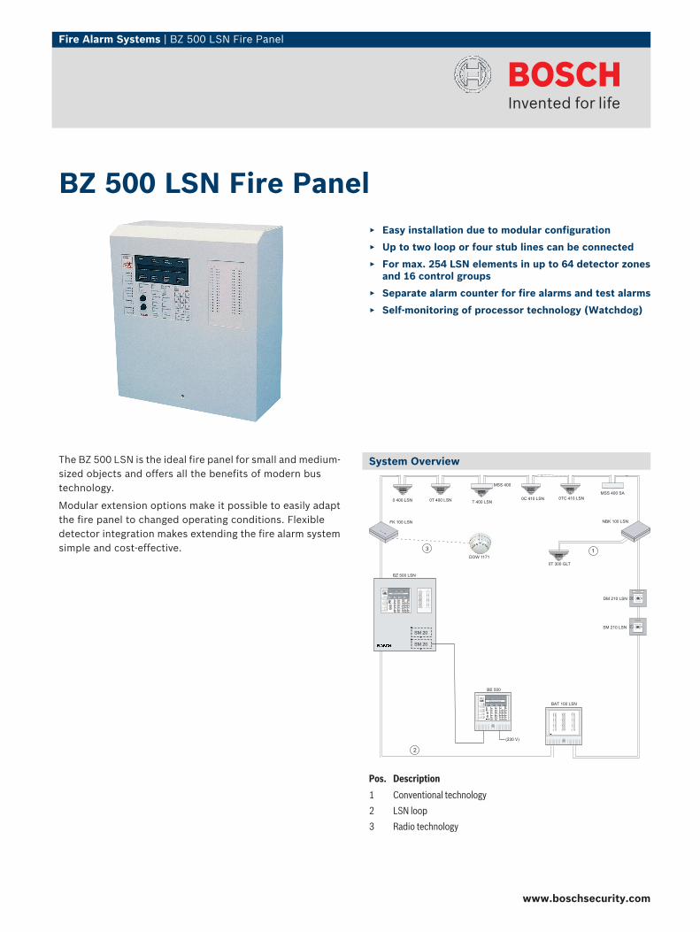
The BZ 500 LSN is the ideal fire panel for small and medium-sized objects and offers all the benefits of modern bustechnology.
Modular extension options make it possible to easily adaptthe fire panel to changed operating conditions. Flexibledetector integration makes extending the fire alarm systemsimple and cost-effective.
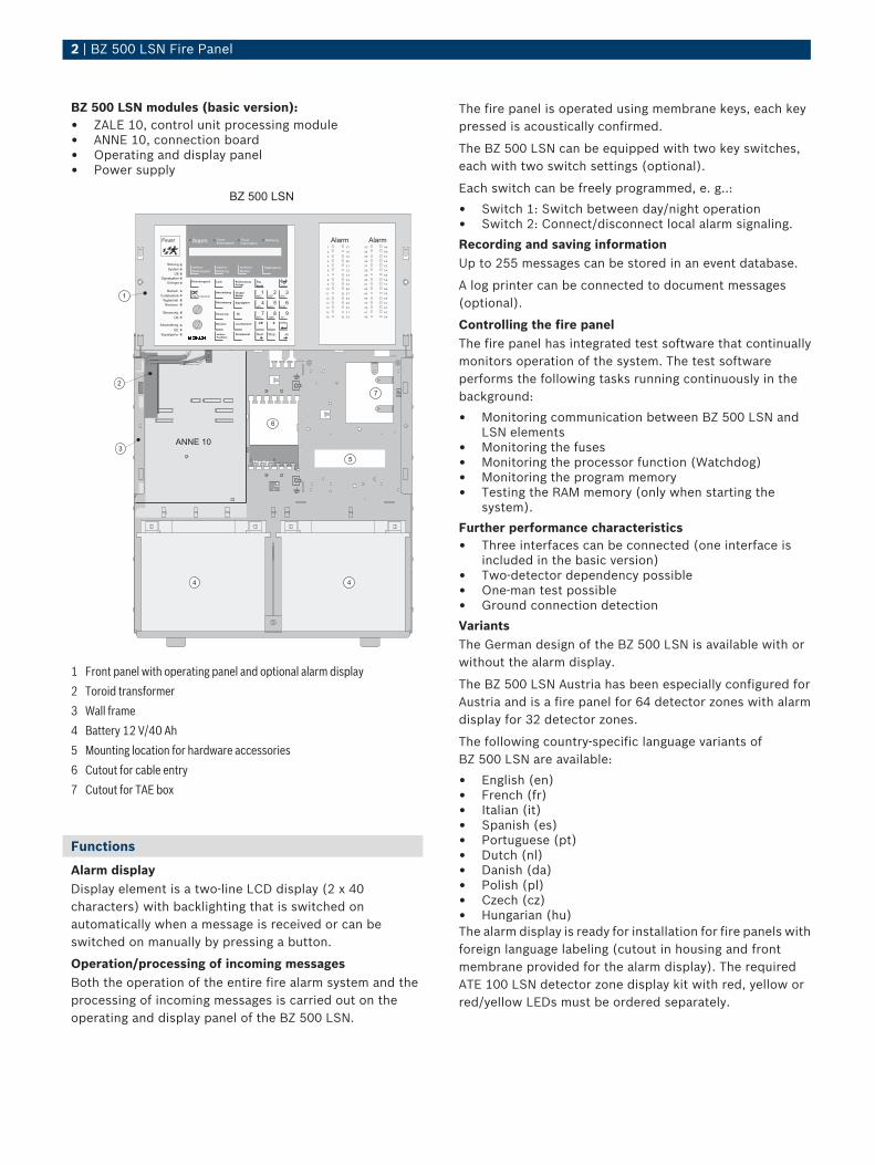
System Overview
BE 500
BAT 100 LSN
(230 V)
Fire Alarm
Next TypeMessage
FireExternal Alarm
NextMessage
1 2 3
7 8
CE
no yesStop
Enter
Day/NightOn/Off
ResetSystem
Code
Malfunction
System
Transmission unit
Sounder/Strobe
Power supply
Operation
Code operation
Day operation
Maintenance
Switch off
Transmission unit
Sounder/Strobe
Control
Transmission unit
VerificationTime
ZoneDetector
SwitchOff
SounderStrobe
Reset
TransmissionUnit
Control
ExtinguishingSystem
Maintenance
SwitchingPoint
Addit.Function
Silence buzzer
0
9
5 64
BZ 500 LSN
FireInternal Alarm
Next TypeDetector
Message
Action
ALARM ALARM
1 3317 49
16 4832 64
ALARM
65 81
80 96
BOSCH Security Systems
Scheibe einschlagen
Knopf drücken
0 400 LSN 0T 400 LSN 0C 410 LSN 0TC 410 LSNT 400 LSN
MSS 400 SA
MSS 400
DM 210 LSN
Feuerwehr
Scheibe einschlagen
SM 210 LSN
Feuerwehr
0T 300 GLT
FK 100 LSN NBK 100 LSN
DOW 1171
Fire Alarm
Next TypeMessage
FireExternal Alarm
NextMessage
1 2 3
7 8
CE
no yesStop
ALARM ALARM
1 3332 49
16 3348 64
Enter
Day/NightOn/Off
ResetSystem
Code
Malfunction
System
Transmission unit
Sounder/Strobe
Power supply
Operation
Code operation
Day operation
Maintenance
Switch off
Transmission unit
Sounder/Strobe
Control
Transmission unit
VerificationTime
ZoneDetector
SwitchOff
SounderStrobe
Reset
TransmissionUnit
Control
ExtinguishingSystem
Maintenance
SwitchingPoint
Addit.Function
Silence buzzer
0
9
5 64
FireInternal Alarm
Next TypeDetector
Message
Action
BOSCH Security Systems
SM 20
SM 20
1
2
3
Pos. Description
1 Conventional technology
2 LSN loop
3 Radio technology
BZ 500 LSN Fire Panel▶ Easy installation due to modular configuration
▶ Up to two loop or four stub lines can be connected
▶ For max. 254 LSN elements in up to 64 detector zonesand 16 control groups
▶ Separate alarm counter for fire alarms and test alarms
▶ Self-monitoring of processor technology (Watchdog)
www.boschsecurity.com
2 | BZ 500 LSN Fire Panel
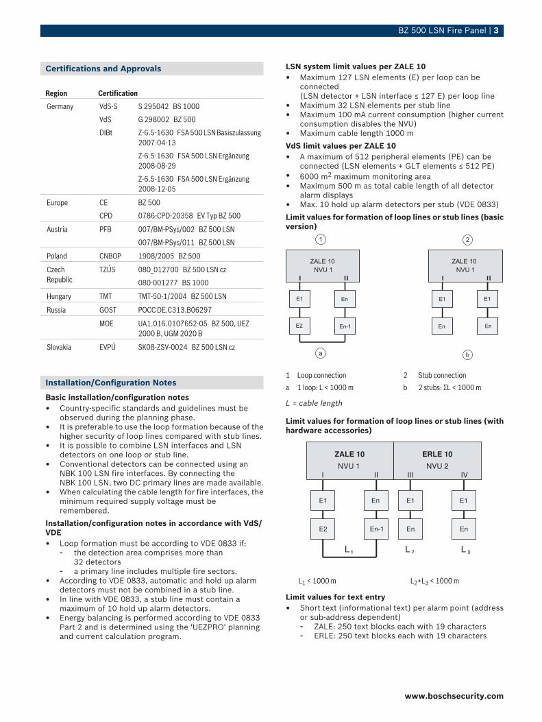
BZ 500 LSN modules (basic version):• ZALE 10, control unit processing module• ANNE 10, connection board• Operating and display panel• Power supply
1
2
3
4
5
6
7
8
9
1 0
1 1
1 2
1 3
1 4
1 5
1 6
1 7
1 8
1 9
2 0
2 1
2 2
2 3
2 4
2 5
2 6
2 7
2 8
2 9
3 0
3 1
3 2
Alarm4 9
5 0
5 1
5 2
5 3
5 4
5 5
5 6
5 7
5 8
5 9
6 0
6 1
6 2
6 3
6 4
Alarm3 3
3 4
3 5
3 6
3 7
3 8
3 9
4 0
4 1
4 2
4 3
4 4
4 5
4 6
4 7
4 8
StörungSystem
ÜESignalgeber
Energie
BetriebCodebetriebTagbetriebRevision
SteuerungÜE
AbschaltungÜE
Signalgeber
Feuer Alarm FeuerExternalarm Internalarm
weitereMeldungsart Meldungweitere Melderweiterer Maßnahme
Erkundungszeit Code Rücksetzung TagNacht
Abschaltung Gruppe
Rücksetzung Signalgeber
Steuerung ÜE
Revision Löschbereich
Schaltpunkt
MelderinternSummer ABC1
DEF2
GHI3
STU7
VWX8
YZ9
JKL4
MNO5
PQR6
0 enter
weitereFunktion
Sirene
nein stop jaCE
1
2
3
4
5
6
7
8
9
1 0
1 1
1 2
1 3
1 4
1 5
1 6
1 7
1 8
1 9
2 0
2 1
2 2
2 3
2 4
2 5
2 6
2 7
2 8
2 9
3 0
3 1
3 2
Alarm4 9
5 0
5 1
5 2
5 3
5 4
5 5
5 6
5 7
5 8
5 9
6 0
6 1
6 2
6 3
6 4
Alarm3 3
3 4
3 5
3 6
3 7
3 8
3 9
4 0
4 1
4 2
4 3
4 4
4 5
4 6
4 7
4 8
Störung
System
Signalgeber
Energie
Betrieb
Codebetrieb
Tagbetrieb
Revision
Steuerung
ÜE
Abschaltung
ÜE
Signalgeber
Feuer Alarm FeuerExternalarm
MeldungFeuerInternalarm
weitereMeldungsart Meldung
weitereMelderweiterer Maßnahme
Erkundungszeit Code RücksetzungAnlage
Tag
Nacht
Abschaltung GruppeMelder
Rücksetzung Signalgeber
Steuerung ÜE
Revision Löschbereich
Schaltpunkt
interner Summer ABC
1DEF
2GHI
3
STU
7VWX
8YZ
9
JKL
4MNO
5PQR
6
0 enter
weitereFunktion
Sirene
Nein Stop Ja
CE
ANNE 10
BZ 500 LSN
ÜE
1
2
3
5
6
7
44
1 Front panel with operating panel and optional alarm display
2 Toroid transformer
3 Wall frame
4 Battery 12 V/40 Ah
5 Mounting location for hardware accessories
6 Cutout for cable entry
7 Cutout for TAE box
Functions
Alarm displayDisplay element is a two-line LCD display (2 x 40characters) with backlighting that is switched onautomatically when a message is received or can beswitched on manually by pressing a button.
Operation/processing of incoming messagesBoth the operation of the entire fire alarm system and theprocessing of incoming messages is carried out on theoperating and display panel of the BZ 500 LSN.
The fire panel is operated using membrane keys, each keypressed is acoustically confirmed.
The BZ 500 LSN can be equipped with two key switches,each with two switch settings (optional).
Each switch can be freely programmed, e. g..:
• Switch 1: Switch between day/night operation• Switch 2: Connect/disconnect local alarm signaling.
Recording and saving informationUp to 255 messages can be stored in an event database.
A log printer can be connected to document messages(optional).
Controlling the fire panelThe fire panel has integrated test software that continuallymonitors operation of the system. The test softwareperforms the following tasks running continuously in thebackground:
• Monitoring communication between BZ 500 LSN andLSN elements
• Monitoring the fuses• Monitoring the processor function (Watchdog)• Monitoring the program memory• Testing the RAM memory (only when starting the
system).
Further performance characteristics• Three interfaces can be connected (one interface is
included in the basic version)• Two-detector dependency possible• One-man test possible• Ground connection detection
VariantsThe German design of the BZ 500 LSN is available with orwithout the alarm display.
The BZ 500 LSN Austria has been especially configured forAustria and is a fire panel for 64 detector zones with alarmdisplay for 32 detector zones.
The following country-specific language variants ofBZ 500 LSN are available:
• English (en)• French (fr)• Italian (it)• Spanish (es)• Portuguese (pt)• Dutch (nl)• Danish (da)• Polish (pl)• Czech (cz)• Hungarian (hu)The alarm display is ready for installation for fire panels withforeign language labeling (cutout in housing and frontmembrane provided for the alarm display). The requiredATE 100 LSN detector zone display kit with red, yellow orred/yellow LEDs must be ordered separately.
BZ 500 LSN Fire Panel | 3
Certifications and Approvals
Region Certification
Germany VdS-S S 295042 BS 1000
VdS G 298002 BZ 500
DIBt Z-6.5-1630 FSA 500 LSN Basiszulassung2007-04-13
Z-6.5-1630 FSA 500 LSN Ergänzung2008-08-29
Z-6.5-1630 FSA 500 LSN Ergänzung2008-12-05
Europe CE BZ 500
CPD 0786-CPD-20358 EV Typ BZ 500
Austria PFB 007/BM-PSys/002 BZ 500 LSN
007/BM-PSys/011 BZ 500 LSN
Poland CNBOP 1908/2005 BZ 500
CzechRepublic
TZÚS 080_012700 BZ 500 LSN cz
080-001277 BS 1000
Hungary TMT TMT-50-1/2004 BZ 500 LSN
Russia GOST POCC DE.C313.B06297
MOE UA1.016.0107652-05 BZ 500, UEZ2000 B, UGM 2020 B
Slovakia EVPÚ SK08-ZSV-0024 BZ 500 LSN cz
Installation/Configuration Notes
Basic installation/configuration notes• Country-specific standards and guidelines must be
observed during the planning phase.• It is preferable to use the loop formation because of the
higher security of loop lines compared with stub lines.• It is possible to combine LSN interfaces and LSN
detectors on one loop or stub line.• Conventional detectors can be connected using an
NBK 100 LSN fire interfaces. By connecting theNBK 100 LSN, two DC primary lines are made available.
• When calculating the cable length for fire interfaces, theminimum required supply voltage must beremembered.
Installation/configuration notes in accordance with VdS/VDE• Loop formation must be according to VDE 0833 if:
- the detection area comprises more than32 detectors
- a primary line includes multiple fire sectors.• According to VDE 0833, automatic and hold up alarm
detectors must not be combined in a stub line.• In line with VDE 0833, a stub line must contain a
maximum of 10 hold up alarm detectors.• Energy balancing is performed according to VDE 0833
Part 2 and is determined using the 'UEZPRO' planningand current calculation program.
LSN system limit values per ZALE 10• Maximum 127 LSN elements (E) per loop can be
connected (LSN detector + LSN interface ≤ 127 E) per loop line
• Maximum 32 LSN elements per stub line• Maximum 100 mA current consumption (higher current
consumption disables the NVU)• Maximum cable length 1000 m
VdS limit values per ZALE 10• A maximum of 512 peripheral elements (PE) can be
connected (LSN elements + GLT elements ≤ 512 PE)• 6000 m2 maximum monitoring area• Maximum 500 m as total cable length of all detector
alarm displays• Max. 10 hold up alarm detectors per stub (VDE 0833)
Limit values for formation of loop lines or stub lines (basicversion)
E1
En En
ZALE 10
NVU 1
I II
E1
E2
En
En-1
I II
E1
ZALE 10
NVU 1
a b
21
1 Loop connection 2 Stub connection
a 1 loop: L < 1000 m b 2 stubs: ΣL < 1000 m
L = cable length
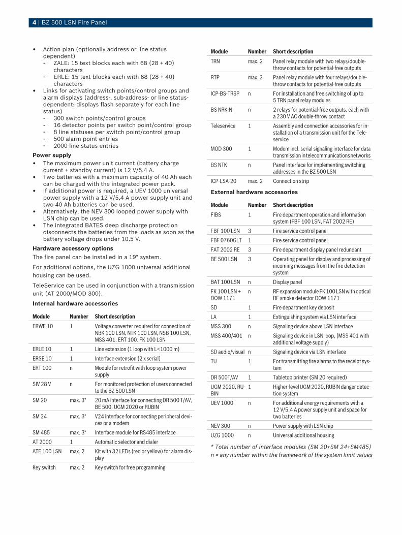
Limit values for formation of loop lines or stub lines (withhardware accessories)
E1
En En
ZALE 10
NVU 1
I II
E1
E2
En
En-1
III IV
E1
ERLE 10
NVU 2
L 3L 2L 1
L1 < 1000 m L2+L3 < 1000 m
Limit values for text entry• Short text (informational text) per alarm point (address
or sub-address dependent)- ZALE: 250 text blocks each with 19 characters- ERLE: 250 text blocks each with 19 characters
www.boschsecurity.com
4 | BZ 500 LSN Fire Panel
• Action plan (optionally address or line statusdependent)- ZALE: 15 text blocks each with 68 (28 + 40)
characters- ERLE: 15 text blocks each with 68 (28 + 40)
characters• Links for activating switch points/control groups and
alarm displays (address-, sub-address- or line status-dependent; displays flash separately for each linestatus)- 300 switch points/control groups- 16 detector points per switch point/control group- 8 line statuses per switch point/control group- 500 alarm point entries- 2000 line status entries
Power supply• The maximum power unit current (battery charge
current + standby current) is 12 V/5.4 A.• Two batteries with a maximum capacity of 40 Ah each
can be charged with the integrated power pack.• If additional power is required, a UEV 1000 universal
power supply with a 12 V/5,4 A power supply unit andtwo 40 Ah batteries can be used.
• Alternatively, the NEV 300 looped power supply withLSN chip can be used.
• The integrated BATES deep discharge protectiondisconnects the batteries from the loads as soon as thebattery voltage drops under 10.5 V.
Hardware accessory optionsThe fire panel can be installed in a 19" system.
For additional options, the UZG 1000 universal additionalhousing can be used.
TeleService can be used in conjunction with a transmissionunit (AT 2000/MOD 300).
Internal hardware accessories
Module Number Short description
ERWE 10 1 Voltage converter required for connection ofNBK 100 LSN, NTK 100 LSN, NSB 100 LSN,MSS 401. ERT 100. FK 100 LSN
ERLE 10 1 Line extension (1 loop with L<1000 m)
ERSE 10 1 Interface extension (2 x serial)
ERT 100 n Module for retrofit with loop system powersupply
SIV 28 V n For monitored protection of users connectedto the BZ 500 LSN
SM 20 max. 3* 20 mA interface for connecting DR 500 T/AV,BE 500. UGM 2020 or RUBIN
SM 24 max. 3* V24 interface for connecting peripheral devi-ces or a modem
SM 485 max. 3* Interface module for RS485 interface
AT 2000 1 Automatic selector and dialer
ATE 100 LSN max. 2 Kit with 32 LEDs (red or yellow) for alarm dis-play
Key switch max. 2 Key switch for free programming
Module Number Short description
TRN max. 2 Panel relay module with two relays/double-throw contacts for potential-free outputs
RTP max. 2 Panel relay module with four relays/double-throw contacts for potential-free outputs
ICP‑BS‑TRSP n For installation and free switching of up to5 TRN panel relay modules
BS NRK-N n 2 relays for potential-free outputs, each witha 230 V AC double-throw contact
Teleservice 1 Assembly and connection accessories for in-stallation of a transmission unit for the Tele-service
MOD 300 1 Modem incl. serial signaling interface for datatransmission in telecommunications networks
BS NTK n Panel interface for implementing switchingaddresses in the BZ 500 LSN
ICP‑LSA‑20 max. 2 Connection strip
External hardware accessories
Module Number Short description
FIBS 1 Fire department operation and informationsystem (FBF 100 LSN, FAT 2002 RE)
FBF 100 LSN 3 Fire service control panel
FBF 0760GLT 1 Fire service control panel
FAT 2002 RE 3 Fire department display panel redundant
BE 500 LSN 3 Operating panel for display and processing ofincoming messages from the fire detectionsystem
BAT 100 LSN n Display panel
FK 100 LSN +DOW 1171
n RF expansion module FK 100 LSN with opticalRF smoke detector DOW 1171
SD 1 Fire department key deposit
LA 1 Extinguishing system via LSN interface
MSS 300 n Signaling device above LSN interface
MSS 400/401 n Signaling device in LSN loop, (MSS 401 withadditional voltage supply)
SD audio/visual n Signaling device via LSN interface
TU 1 For transmitting fire alarms to the receipt sys-tem
DR 500T/AV 1 Tabletop printer (SM 20 required)
UGM 2020, RU-BIN
1 Higher-level UGM 2020, RUBIN danger detec-tion system
UEV 1000 n For additional energy requirements with a12 V/5.4 A power supply unit and space fortwo batteries
NEV 300 n Power supply with LSN chip
UZG 1000 n Universal additional housing
* Total number of interface modules (SM 20+SM 24+SM485)n = any number within the framework of the system limit values

BZ 500 LSN Fire Panel | 5
For further applications like monitored activation ofsignaling devices or extinguishing systems, refer to theFLM-20 Series Interface Modules.
Parts Included
BZ 500 LSN Fire Panel de, en, fr, it, es, pt, nl, da, pl, cz, hu
Qty. Components
1 Sheet steel housing, painted light gray
1 Operating panel with labeling in national language
1 ANNE 10 (with a V24 interface)
1 ZALE 10
1 5.4 A power supply unit
1* Front membrane for the alarm display with country-specific la-beling (without ATE 100 LSN)
* with the exception of BZ 500 LSN de
BZ 500 LSN Fire Panel de and at, with alarm display
Qty. Components
1 Sheet steel housing, painted light gray
1 Operating panel with labeling in national language
1 ANNE 10 (with a V24 interface)
1 ZALE 10
1 5.4 A power supply unit
1 ATE 100 LSN kit with 32 red LEDs
Technical Specifications
Electrical
AC line voltage 230 V AC (-15%/+10%), 50 Hz
Current consumption
• In standby mode 200 mA
• During an alarm 270 mA
• Display/illumination 200 mA
• Additional per NVU 380 mA
Power consumption 110 W (fully equipped model)
Operating voltage 11 V DC . . . 15 V DC(13.9 V DC at 30 °C)
Battery capacity 80 Ah (2x 12 V/40 Ah)
Battery charge voltage 13.8V DC
Back-up time Max. 72 h
Mechanics
Dimensions (W x H x D)
• With key switch (incl. key) 443 x 501 x 230 mm
• Without key switch 443 x 501 x 215 mm
Weight (fully equipped model)
• Without batteries 17 kg
• With 2 batteries (12 V/40 Ah) 46 kg
Color
• Housing Light-gray, RAL 9002
• Operating panel Pale gray, Bosch NCS
Environmental conditions
Protection class as per EN 60529 IP 40
Classes of equipment as perEN 60950
Class II equipment
Permissible operating temperature -5 °C . . . +45 °C
Permissible storage temperature -20 °C . . . +60 °C
Planning a Local SecurityNetwork LSN
Maximum current consumption perLSN loop
100 mA
Max. number of LSN elements
• In basic model (ZALE 10) 127
• With extension (ERLE 10) 254
Maximum LSN cable length 1,000 m
Cable for the Local SecurityNetworkLSN
J-Y (St) Y n x 2 x 0.6 orJ-Y (St) Y n x 2 x 0.8
Ordering Information
BZ 500 LSN Fire Panel de, without AlarmDisplay
BZ 500-DE
BZ 500 LSN Fire Panel de, with AlarmDisplay for 32 Det. Zones
BZ 500-MG-EAZ-DE
BZ 500 LSN Fire Panel Austria, with AlarmDisplay for 32 Det. Zones
BZ 500 A
BZ 500 LSN Fire Panel en BZ 500-GB
BZ 500 LSN Fire Panel fr BZ 500 FR
BZ 500 LSN Fire Panel it BZ 500 IT
BZ 500 LSN Fire Panel es BZ 500 ES
BZ 500 LSN Fire Panel pt BZ 500 PT
BZ 500 LSN Fire Panel nl BZ 500-MG-EAZ-NL
BZ 500 LSN Fire Panel da BZ 500 DA
BZ 500 LSN Fire Panel pl BZ 500 PL
BZ 500 LSN Fire Panel cs BZ 500 CZ
BZ 500 LSN Fire Panel hu BZ 500 HU
www.boschsecurity.com
6 | BZ 500 LSN Fire Panel
Americas:Bosch Security Systems, Inc.130 Perinton ParkwayFairport, New York, 14450, USAPhone: +1 800 289 0096Fax: +1 585 223 [email protected]
Europe, Middle East, Africa:Bosch Security Systems B.V.P.O. Box 800025600 JB Eindhoven, The NetherlandsPhone: + 31 40 2577 284Fax: +31 40 2577 [email protected]
Asia-Pacific:Robert Bosch (SEA) Pte Ltd, Security Systems38C Jalan PemimpinSingapore 577180Phone: +65 6319 3453Fax: +65 6319 [email protected]
Represented by
© Bosch Security Systems Inc. 2009 | Data subject to change without noticeT275040779 | Cur: en-US, V11, 30 Mar 2009