by: sherwood industries ltd owner’s manualenviro.com/custom_content/docs/manuals/c-10235...
TRANSCRIPT

SHERWOOD INDUSTRIES IS AN ENVIRONMENTALLY RESPONSIBLE COMPANY. THIS MANUAL IS PRINTED ON RECYCLED PAPER.
B Y : S H E R W O O D I N D U S T R I E S L T D
OWNER’S MANUAL
PLEASE KEEP THESE INSTRUCTIONS FOR FUTURE REFERENCE
WHAT TO DO IF YOU SMELL GAS• Open windows/extinguish any open flame.• Do not try to light any appliance.• Do not touch any electrical switch or use any phone
in your building.• Immediately call your gas supplier from a neighbour’s
phone. Follow the gas supplier’s instructions.• If you cannot reach your gas supplier, call the fire
department.
WARNINGIf the information in this manual is not followed exactly, a fire or
explosion may result causing property damage, personal injury or loss of
life. Installation and service must be performed by a qualified installer, service agency or the gas supplier.
50-304
Accent 20 BV
This appliance is only for use with the type of gas indicated
on the rating plate. This appliance is not convertible for use with other gases, unless a
certified kit is used.
FOR YOUR SAFETYDo not store or use gasoline or other flammable vapours and liquids in the vicinity of this or any other appliance.
Massachusetts installations (Warning): This product must be installed by a licensed plumber or gas fitter when installed within the Commonwealth of Massachusetts. Other Massachusetts code requirements: Flexible connector must not be longer than 36in, shut off valve must be a “T” handle gas cock; only direct vent sealed combustion products are approved for bedrooms/bathrooms; fireplace dampers must be removed or welded in the open position prior to the installation of a fireplace insert or gas log.
2
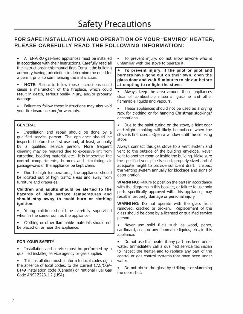
FOR SAFE INSTALLATION AND OPERATION OF YOUR “ENVIRO” HEATER, PLEASE CAREFULLY READ THE FOLLOWING INFORMATION:
• All ENVIRO gas-fired appliances must be installed in accordance with their instructions. Carefully read all the instructions in this manual first. Consult the building authority having jurisdiction to determine the need for a permit prior to commencing the installation.
• NOTE: Failure to follow these instructions could cause a malfunction of the fireplace, which could result in death, serious bodily injury, and/or property damage.
• Failure to follow these instructions may also void your fire insurance and/or warranty.
GENERAL
• Installation and repair should be done by a qualified service person. The appliance should be inspected before the first use and, at least, annually by a qualified service person. More frequent cleaning may be required due to excessive lint from carpeting, bedding material, etc. It is imperative the control compartments, burners and circulating air passageways of the appliance be kept clean.
• Due to high temperatures, the appliance should be located out of high traffic areas and away from furniture and draperies.
Children and adults should be alerted to the hazards of high surface temperatures and should stay away to avoid burn or clothing ignition.
• Young children should be carefully supervised when in the same room as the appliance.
• Clothing or other flammable materials should not be placed on or near the appliance.
FOR YOUR SAFETY
• Installation and service must be performed by a qualified installer, service agency or gas supplier.
• This installation must conform to local codes or, in the absence of local codes, to the current CAN/CGA-B149 installation code (Canada) or National Fuel Gas Code ANSI Z223.1.2 (USA)
• To prevent injury, do not allow anyone who is unfamiliar with the stove to operate it.
• To prevent injury, if the pilot or pilot and burners have gone out on their own, open the glass door and wait 5 minutes to air out before attempting to re-light the stove.
• Always keep the area around these appliances clear of combustible material, gasoline and other flammable liquids and vapours.
• These appliances should not be used as a drying rack for clothing or for hanging Christmas stockings/decorations.
• Due to the paint curing on the stove, a faint odor and slight smoking will likely be noticed when the stove is first used. Open a window until the smoking stops.
Always connect this gas stove to a vent system and vent to the outside of the building envelope. Never vent to another room or inside the building. Make sure the specified vent pipe is used, properly sized and of adequate height to provide sufficient draft. Inspect the venting system annually for blockage and signs of deterioration.
WARNING: Failure to position the parts in accordance with the diagrams in this booklet, or failure to use only parts specifically approved with this appliance, may result in property damage or personal injury.
WARNING: Do not operate with the glass front removed, cracked or broken. Replacement of the glass should be done by a licensed or qualified service person.
• Never use solid fuels such as wood, paper, cardboard, coal, or any flammable liquids, etc., in this appliance.
• Do not use this heater if any part has been under water. Immediately call a qualified service technician to inspect the heater and to replace any part of the control or gas control systems that have been under water.
• Do not abuse the glass by striking it or slamming the door shut.
Safety Precautions

Table of Contents
3
Safety Precautions.......................................................................................2
Table of Contents.........................................................................................3
Codes And Approvals....................................................................................4
Specifications...............................................................................................6
Dimensions.......................................................................................6
Clearances to Combustibles................................................................6
Rating Label Location........................................................................6
Operating Instructions..................................................................................7
Lighting Instructions..........................................................................7
Maintenance And Service..............................................................................8
Routine Maintenance.........................................................................8
Adjusting venturi air settings............................................................10
Fuel Conversion...............................................................................11
Initial Installation.......................................................................................12
Preparation For Installation..............................................................12
Assembling And Installation Instructions...........................................12
Venting...........................................................................................13
Venting Fireplace Inserts..................................................................13
Gas Line Connection........................................................................14
Electrical System.............................................................................15
Removing and Installing The Blower..................................................15
Secondary Installation................................................................................16
Log Set and Ember Installation.........................................................16
Removing And Installing The Brick Panels.........................................18
Cast Iron Surround Panel Extension Trim Kit......................................19
Trouble Shooting........................................................................................20
Parts List - Cast..........................................................................................21
Parts Diagram - Cast..................................................................................23
Parts List - Surround Panels........................................................................24
Parts Diagram - Surround Panels.................................................................25
Parts List - Components..............................................................................26
Parts Diagram - Components.......................................................................27
Warranty..................................................................................................28
Installation Data Sheet...............................................................................29

4
B VENT ONLY: This vent type is identified by the suffix BV. This appliance draws in room air for combustion and vent dilution air.This appliance has been tested and approved for installations from 0 feet to 2000 feet (810 m) above sea level.
In the USA: The appliance may be installed at higher altitudes. Please refer to your American Gas Association guidelines which state: the sea level rated input of Gas Designed Appliances installed at elevations above 2000 (610 m) feet is to be reduced 4% for each 1000 feet (305 m) above sea level. Refer also to local authorities or codes which have jurisdiction in your area regarding the de-rate guidelines.
In Canada: When the appliance is installed at elevations above 4500 feet (1372 m), the certified high altitude rating shall be reduced at the rate of 4% for each additional 1000 feet (305 m).
• This appliance has been tested by INTERTEK (Warnock Hersey) and found to comply with the established VENTED GAS FIREPLACE HEATER standards in CANADA and the USA as follows:
VENTED GAS FIREPLACE HEATER (Accent 20 BV; NG/LPG)
TESTED TO: ANSI Z21.88a-2003/CSA 2.33a-2003 VENTED GAS FIREPLACE HEATERS
CAN/CGA 2.17-M91 GAS FIRED APPLIANCES FOR HIGH ALTITUDES
CSA P.4.1-02 TESTING METHOD FOR MEASURING ANNUAL FIREPLACE EFFICIENCY
This ENVIRO Accent 20 BV Fireplace: • Has been certified for use with either natural or propane gases. (See rating label.)• Is not for use with solid fuels.• Is approved for bedroom or bed sitting room. (IN CANADA: must be installed with a listed wall
thermostat. IN USA: see current ANSI Z223.1 for installation instructions.)
Codes And Approvals
• Must be installed in accordance with local codes. If none exist, use current installation code CAN/CGA B149 in Canada or ANSI Z223.1/NFPA 54 in the USA.
• Must be properly connected to an approved venting system and not connected to a chimney flue serving a separate solid-fuel burning appliance.
IMPORTANT NOTICE (Regarding first fire up): When the unit is turned on for the first time, it should be turned onto high without the fan on for the first 4 hours. This will cure the paint, logs, gasket material and other products used in the manufacturing process. It is advisable to open a window or door, as the unit will start to smoke and can irritate some people. After the unit has gone through the first burn, turn the unit off including the pilot, let the unit get cold then remove the glass door and clean it with a good gas fireplace glass cleaner, available at your local ENVIRO dealer.

NATURAL GAS INPUT: 20,000 BTU/hr, (4.69KW) ORIFICE #45 DMS PROPANE INPUT: 20,000 BTU/hr, (4.98KW) ORIFICE #55 DMS
WARNING: For installation only in a solid fuel burning fireplace with a working flue and constructed of a non-combustible material using a chimney liner kit.
CONVERSION OF ZERO CLEARANCE FACTORY BUILT FIREPLACES:
The following instructions cover Sherwood Industries Ltd. policy for Gas-Fired Appliances (inserts) to be retro-fitted into existing factory built fireplaces with replacement parts removed.
GENERAL REQUIREMENTS:
Background:
A gas-fired insert is approved for use in an existing masonry or listed factory-built fireplaces without any alterations. If the factory or masonry fireplace is altered its warranty is void.
Recent practice in the field is to remove parts that do not require cutting, bending or breaking from the factory built fireplace in order to allow the insert to fit.
Sherwood Industries Ltd. Policy:
Intretek has approved listed factory-built fireplaces as a certified zero clearance kit, provided that the following conditions have been met:
1. The removal of any part will not weaken the stuctural integrity of the factory-built fireplace.
2. The factory-built fireplace is in good condition.
3. There are no alterations in the form of cutting, bending, or breaking any parts.
4. Firebricks may be removed.
5. A permanent label must be supplied with the insert, with instructions to affix it to the firebox of the factory-built fireplace. It will have wording to the effect:
WARNING - THIS FIREPLACE MUST ONLY BE OPERATED WITH A GAS INSERT ONLY - REMOVAL OF THE INSERT AND THE USE OF SOLID FUEL IS PROHIBITED AND MAY CAUSE A FIRE HAZARD.
REPLACEMENT PARTS INCLUDE: Fire bricks, smoke shield, flue damper, glass doors, and firescreens.
Codes And Approvals
5

6
SpecificationsWARNING:
Operation of this heater when not connected to a properly installed and maintained venting system can result in carbon monoxide (CO) poisoning and possible death.Dimensions:
40"(1016mm)
2"(51mm)
23"(584mm)
36 1/8"(918mm)
24"(610mm)
24 1/4"(616mm)
17"(432mm)
14 7/8"(378mm)
13 ½"(343mm)
11½"(292mm)
8" (203mm)Mantel
16 5/8"(422mm)
17½"(445mm)
19"(483mm)
Figure 1. Accent 20 Dimensions.
Additional Dimensions:
Depth of unit into fireplace 13½” (343 mm)
Depth of unit out of fireplace 1⅜” (35 mm)
Minimum firebox size: Width 27” (656 mm) Hieght 19” (483 mm) Depth 15” (381 mm)
ClearanCes to Combustibles:
You must maintain sufficient clearances for operation, service and maintenance.
Mantle pillar to side of surround panel 2” (51 mm)
Bottom of unit to 8” wide mantle 40” (1016 mm)
Minimum non-combustible surface in front of unit 8” (203 mm)
CLEARANCES MUST BE SUFFICIENT TO ALLOW ACCESS FOR MAINTENANCE AND SERVICE
rating label loCation:
The rating label is located under the firebox and is attached to a rectangular metal sheet that is chained to the fireplace.
7
Operating InstructionsFOR YOUR SAFETY READ COMPLETELY BEFORE OPERATING.
lighting instruCtions:
FOR
YO
UR
SA
FETY
REA
D B
EFO
RE
OPE
RAT
ING
W
AR
NIN
G: I
F YO
U D
O N
OT
FOLL
OW
TH
ES
E IN
STR
UC
TIO
NS
EXA
CTL
Y, A
FIR
E O
R E
XPLO
SIO
N
MA
Y R
ES
ULT
CA
US
ING
YO
U D
O N
OT
PR
OP
ER
TY D
AM
AG
E, P
ER
SO
NA
L IN
JUR
Y O
R L
OS
S O
F LI
FEA
) Th
is ap
plian
ce is
equip
ped w
ith a
pilot,
whic
h mus
t be l
it by h
and b
y foll
owing
thes
e ins
tructi
ons e
xactl
y. B
) BE
FORE
LIGH
TING
smell
all a
roun
d the
app
lianc
e are
a for
gas,
and n
ext to
the f
loor
beca
use s
ome g
as is
heav
ier th
an ai
r and
will
settle
on th
e floo
r. W
HAT
TO D
O IF
YOU
SME
LL G
AS:
Do
not
try to
light
any a
pplia
nce.
Do
not
touch
any e
lectric
al sw
itch;
do no
t use
any
phon
e in y
our b
uildin
g.
Im
media
tely c
all yo
ur ga
s sup
plier
from
a ne
ighbo
r’s ph
one.
Follo
w th
e gas
su
pplie
r’s in
struc
tions
.
If you
cann
ot re
ach y
our g
as su
pplie
r, ca
ll the
fire d
epar
tmen
t. C
) Us
e only
your
hand
to pu
sh in
or tu
rn th
e gas
contr
ol kn
ob.
Neve
r use
tools
. If th
e
knob
will
not p
ush i
n or t
urn b
y han
d, do
not tr
y to r
epair
it. C
all a
quali
fied s
ervic
e tec
hnici
an. F
orce
or at
tempte
d rep
air m
ay re
sult i
n a fir
e or e
xplos
ion.
D)
Do n
ot us
e this
appli
ance
if an
y par
t has
bee
n und
er w
ater.
Imm
ediat
ely ca
ll a
quali
fied s
ervic
e tec
hnici
an to
insp
ect th
e app
lianc
e and
to re
place
any p
art o
f the
contr
ol sy
stem
and a
ny g
as co
ntrol
which
has b
een u
nder
wate
r
LIG
HTI
NG
INST
RU
CTI
ON
SW
ARNI
NG: T
he ga
s valv
e has
an lo
ckou
t dev
ice w
hich w
ill no
t allo
w the
pilot
burn
er to
be re
lit un
til the
ther
moc
ouple
has c
ooled
. Allo
w ap
prox
. 60 s
econ
ds fo
r the
ther
moco
uple
to co
ol.
1. ST
OP! R
ead t
he sa
fety i
nform
ation
abov
e on t
his la
bel.
2. Tu
rn th
e the
rmos
tat to
the l
owes
t sett
ing
3. Tu
rn of
f all e
lectric
al po
wer t
o the
appli
ance
4.
Set th
e bur
ner s
witch
to th
e midd
le “o
ff”
posit
ion ( lo
cate
d on t
he to
p-rig
ht sid
e of
the su
rroun
d pa
nel s
et).
5. De
pres
s pilo
t gas
knob
sligh
tly an
d tur
n clo
ckwi
se
to t
he “o
ff’ po
sition
. 6.
Wait
five (
5) m
inutes
to cl
ear o
ut an
y gas
. If y
ou sm
ell ga
s inc
luding
near
the f
loor,
STOP
! Foll
ow “
B” in
the a
bove
safet
y info
rmati
on If
you d
on’t s
mell g
as go
to ne
xt ste
p.
7. Fin
d pilo
t -loc
ated i
n betw
een t
he fr
ont a
nd re
ar bu
rner
. 8.
Depr
ess p
ilot k
nob s
lightl
y and
turn
coun
ter-cl
ockw
ise
to “P
ILOT”
. 9.
Push
the p
ilot g
as kn
ob in
fully
and h
old. I
mmed
iately
light
the pi
lot by
pus
hing t
he
push
butto
n piez
o spa
rk ign
itor.
Kee
p kno
b dep
ress
ed fo
r abo
ut 30
seco
nds a
fter
pilot
is lit.
Rele
ase K
nob I
f pilo
t goe
s out,
repe
at ste
ps 4
throu
gh 8.
If the
knob
does
not p
op up
whe
n rele
ased
, stop
and i
mmed
iately
call y
our
servi
ce te
chnic
ian or
gas
supp
lier.
If t
he pi
lot w
ill no
t stay
lit af
ter se
vera
l tries
, tur
n the
gas c
ontro
l kno
b to
“OFF
” and
call y
our s
ervic
e tec
hnici
an or
gas s
uppli
er.
10.
Turn
pilot
gas k
nob c
ounte
r-cloc
kwise
t
o the
“on”
posit
ion. T
urn t
he
burn
er sw
itch t
o th
e “on
” pos
ition(
or “t
herm
osta
t” po
sition
whe
n equ
ipped
). 11
. Tu
rn ga
s “hi/
lo” ou
tput k
nob a
nd/or
ther
mosta
t to t
he de
sire d
settin
g. 12
. Tu
rn on
all e
lectric
al po
wer t
o the
unit .
TO T
UR
N O
FF G
AS
TO A
PPLI
AN
CE
1. Se
t the t
herm
ostat
to lo
west
settin
g . 2.
Turn
off a
ll elec
trical
powe
r to t
he ap
plian
ce if
servi
ce is
to be
per
forme
d. 3.
Plac
e bur
ner s
witch
in th
e “off
” pos
ition.
4. De
pres
s the
pilot
gas
knob
sligh
tly a
nd tu
rn cl
ockw
ise
to “
OFF”
. Do N
ot Fo
rce
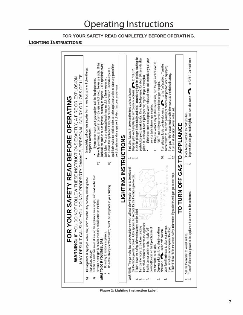
Figure 2: Lighting Instruction Label.

Maintenance And Service
routine maintenanCe:
IMPORTANT NOTE REGARDING FIRST FIRE UP: When the unit is turned on for the first time, it should be turned onto high without the fan on for the first 4 hours. This will cure the paint, logs, gasket material and the other products used in the manufacturing process. It is advisable to open a window or door, as the unit will start to smoke and can irritate some people. After the unit has gone through the first burn turn the unit off including the pilot, let the unit get cold then remove the glass door and clean it with a good gas fireplace glass cleaner, available at your local ENVIRO dealer.
Warning: Failure to position the parts in accordance with this manual, or failure to use only parts specifically approved with this appliance may result in property damage or personal injury.
At least once a year, run through the following procedures to ensure the system is clean and working properly. Depending upon the amount of use, cleaning should be required no more than two or three times per season.
Check the burner to see if all the ports are clear and clean. Check the pilot to make sure it is not blocked by anything. The pilot flame should be blue with little or no yellow on the tips.
The venting system must be periodically examined; it is recommended the examination is done by a qualified agency.
OPENING THE DOOR
1. Turn unit off and wait until the appliance has cooled down.
2. Open the lower louver panel.
3. Use a 5/16” socket to undo the two bolts at the bottom corners of the door.
4. Swing door out, then lift up and out to remove.
5. Ensure the door is properly fastened after cleaning before attempting to re-light the appliance.
CLEANING THE GLASS:
When the fireplace is cool, remove the face of the fireplace along with the glass. Check the gasket material on the back of the glass, making sure that it is attached and intact.
During a cold start up, condensation will sometimes form on the glass. This is a normal condition with all fireplaces. However, this condensation can allow dust and lint to cling to the glass surface. Initial paint curing of the appliance can leave a slight film on the glass, a temporary problem. The glass will need cleaning after the fireplace has gone through the first burn and about two weeks after first burn. Use a mild glass cleaner and a soft cloth. Abrasive cleaners will damage the glass and plated surfaces. Depending on the amount of use, the glass should require cleaning no more than two or three times a season. Do not clean the glass when it is hot.
8

9
Maintenance And Service
REPLACING THE DOOR GLASS:
The glass in the fireplace is a high temperature 5 mm ceramic. If the glass is damaged in any way, a factory replacement is required (see Parts List - Components). Wear gloves when handling damaged glass door assembly to prevent personal injury. When the glass door assembly is being transported, it must be wrapped in newsprint and tape and/or a strong plastic bag. Do not operate with the glass front removed, cracked or broken.
It is highly recommended that the removal and replacement of the glass from the door be done by a licensed or qualified service person.
To Replace:
1. Open the door and remove the glass carefully.
2. Install the new piece of glass with the large bulb in the gasket tape against the unit.
3. Place the tape joint in a bottom corner. Use high temperature silicone to ahere the tape to the door frame.
4. Close door.
The glass must be purchased from an ENVIRO dealer. No substitute materials are allowed.
CLEANING THE INSIDE OF THE FIREBOX:
1. Remove door.
2. Remove the logs carefully, as they are very fragile. Gently remove all the embers and rock wool and place on a paper towel.
3. Vacuum the bottom of the firebox thoroughly. Carefully clean any dust off the logs and brick panels and remove any lint from the burner and pilot. A clean 2” (5 cm) paint brush will work too. At this time, inspect the burner pan for cracking or severe warping. If a problem is suspected, contact the dealer.
4. Replace the logs and embers carefully as in the “Secondary Installation - Log Set and Ember Installation” section.
5. Reseal the door.
6. Re-light the pilot following the instructions on the attached label.
CLEANING PLATED SURFACES:
Painted faces should be wiped with a damp cloth periodically. If a plated face has been purchased, it should be unpacked/unwrapped carefully to avoid getting anything on the surface of the finish, including cleaners, polish and finger prints. It is important to note that fingerprints and other marks can leave a permanent stain on plated finishes. To avoid this, give the face a quick wipe with denatured alcohol on a soft cloth BEFORE lighting the fireplace. Never clean the face when it is hot. Do not use other cleaners as they may leave a residue, which can become permanently etched into the surface.

10
REMOVING BURNER CONTROLS:
1. Shut off gas supply to appliance.
2. Remove surround panels by pulling up then out. Disconnect gas line from the valve. Disconnect harness at connector on side of unit.
3. Open the door and gently remove the logs. Remove the brick panel as per instructions in “Secondary Installation - Removing and Installing The Brick Panels”.
4. Remove the burner tray assembly by removing the two screws in the center of the tray. Pull tray up from the left side, lift tray up and out towards the left.
5. Undo the three screws that hold the burner control tray onto the back firewall. Lift the control tray up on the left side and pull out. Remove wire connector from firebox.
6. Installation is the reverse. When installing the log set refer to “Secondary Installation - Log Set and Ember Installation”.
Caution: Bleed lines before lighting and light pilot with door open.
aDjusting venturi air settings
• There is one venturi and one air shutter on this appliance. The venturi has been set for installation at sea level. Some adjustment may be required.
• To adjust for high altitude: open the lower louvers. Locate the venturi between the burner and control trays. Loosen the setscrews with a long screwdriver and rotate the air shutter until an efficient flame is achieved (refer to Figure 3).
Maintenance And Service
Figure 3. Venturi Adjustment

Fuel Conversion:
Warning: A qualified service technician, in accordance with the manufacturer’s instructions as well as all applicable authority having jurisdiction, shall install this conversion kit. If the information in these instructions is not followed exactly, a fire, explosion or CO poisoning may result. The qualified service agency is responsible for the proper installation of this kit. The installation is not proper or complete until the operation of the converted appliance is checked as specified in the owner’s conversion kit.
Please read and follow these instructions. Also, please read the instruction guidelines provided by S.I.T. on how to remove and install the HI/LO regulator.
Step 1. Carefully inspect all parts supplied with this conversion kit.Step 2. Shut the gas supply off at the shut-off valve.Step 3. Remove the glass, refer to “Maintenance and Service - Routine Maintenance” section.Step 4. Change the regulator on the front of the gas valve (follow the instructions provided by S.I.T.).Step 5. To change the pilot, simply pull the pilot hood straight up to access the pilot injector. Using a
5/32 inch Allen key, remove the pilot injector.Step 6. Install the new pilot injector supplied with this conversion kit. Simply
screw the new injector inside the pilot hood and reinstall the hood by placing the hood on the assembly, line up the key way, and snap into place.
Step 7. Remove the main burner orifice with a ½ inch deep socket.Step 8. Install the new orifice supplied. Be sure to put a bead of pipe-thread
sealant or approved Teflon tape on the orifice before installing into the burner assembly.
Step 9. Reinstall the burner tray, log set, embers, and glass.Step 10. Open shut-off valve at the gas line to the unit.Step 11. Re-light the fireplace to ensure proper operation and proper flame appearance.Step 12. MAKE SURE that the sticker provided by S.I.T. is installed, to signify that the valve has been
converted to a different fuel type. Also, make sure that the rating plate has a conversion label to show this unit has been converted to a different fuel type.
A VISUAL CHECK OF THE REGULATOR KNOB IS NECESSARY TO DETERMINE WHETHER OR NOT THE REGULATOR IS THE CORRECT PART. A 50% TURN DOWN REGULATOR WILL HAVE ONLY ONE CORNER ON THE KNOB
Conversion Kits should contain the following:
1 50% turn down HI/LO regulator NATURAL GAS PROPANE GASwith 3 T-20 Torx screws Pilot Orifice: .62mm. 35mm1 Pilot injector Burner Orifice: #45 DMS #55 DMS 1 Main orifice Venturi Settings: 1/16” open ⅜”openConversion instructionsLabels to show conversion
Maintenance And ServiceQUALIFIED INSTALLERS ONLY
11
Thermopile Thermocouple
Figure 4: Pilot Burning.

1. Remove the unit from its box.2. Open the door by first removing the cover with the nameplate
attached (open valve door and pull nameplate cover side tab to release catch). Undo the two bolts at the bottom of the door. Lift the door up and out to remove. Caution: glass may separate from door.
3. Remove log and ember set and all wrapping material from the stove. Remove wrapping material from log and embers and check for any damage. If damage is observed, do not use unit and contact your local dealer.
4. Measure the distance from the front of the fireplace facing to the front of the flex liner in the chimney.
5. Remove the front exhaust locating screw. Slide the exhaust channel backwards from the unit. Properly secure the exhaust channel to the 3” flexible vent pipe liner previously installed in the chimney using Mil-Pac around the opening and three (3) evenly spaced sheet metal screws. Be careful not to over-stretch the liner.
6. Place the unit part way into the fireplace. Connect the fireplace insert’s rigid gas line to the household gas supply using locally approved methods. Place the electric cable so it can be connected to the power supply. Adjust the leveling legs.
7. Slide the insert into the fireplace, ensuring that the exhaust channel is located under the slide rails on the top of the fireplace insert.
8. Re-install the locating screw and tighten.9. To assemble the surround panel, lay the panel face down on
a soft flat surface and place the brass trim on the surround panel, using the corner brackets to hold the trim to the surround panel.
10. Connect the surround panel wire harness terminal to the stove wire harness terminal on the right side panel.
11. Place the assembled surround panel around the fireplace then align the slots with the screw heads. Push back then down to engage the surround slots on the mounting screws. Make sure the top surround panel sits flat on the stove.
Initial InstallationQUALIFIED INSTALLERS ONLY
PreParation For installation:
• Remove the packaging from the appliance and surround panels, check to make sure there is no damage. Carefully check the glass door. Do not use the unit if it is damaged. In the event damage is found, please report it to your courier and/or your dealer as soon as possible.
• Carefully clean the fireplace and flue before installing the stove. Failure to do so may result in fumes or dirt being blown into the room and may cause a fire leading to serious injury or death.
assembling anD installation instruCtions:
Locating screw
Leveling legs
Figure 5. Preparation for Installation.
Figure 6. Surround Installation.
12
13
Initial InstallationQUALIFIED INSTALLERS ONLY
venting:
WARNING: This appliance has been designed to operate by drawing combustion air and dilution air from the room. It is also designed to draw room air for proper heat circulation from the sides of the unit. Blocking or modifying the louvers in any way can create hazardous situations, either through poor venting or by overheating. It is important that this unit has sufficient air circulation for proper venting and combustion. Provisions must be made for the supply of adequate combustion and ventilation air. These openings must not be blocked. The appliance must not be connected to a chimney flue servicing a separate solid fuel burning appliance.
Note: this heater must be properly connected to a venting system. This heater is equipped with a vent safety shutoff system designed to protect against improper venting of combustion products. This safety switch is located on the rear of the appliance close to the draft hood relief opening. If the switch trips more than once, the venting should be inspected by a qualified service technician for possible blockage or severe down draft conditions.
NOTE: The draft hood must be in the same pressure zone as the air inlet. To inspect draft from the front of the unit, locate the ⅜” tube between the louvers and check for a draft using smoke. A vacuum or suction into the tube will indicate proper drafting.
This model can be vented with 3” aluminum or stainless steel flex vent and/or certified Type B Gas Vent. The flue collar of the appliance will fit inside a standard 3” vent and may be fastened directly to the vent.
Check periodically that the vent is unrestricted and an adequate draft is present when the unit is in operation.
venting FirePlaCe inserts:
WARNING: Operation of this heater when not connected to a properly installed and maintained venting system can result in Carbon Monoxide (CO) poisoning and possible death.
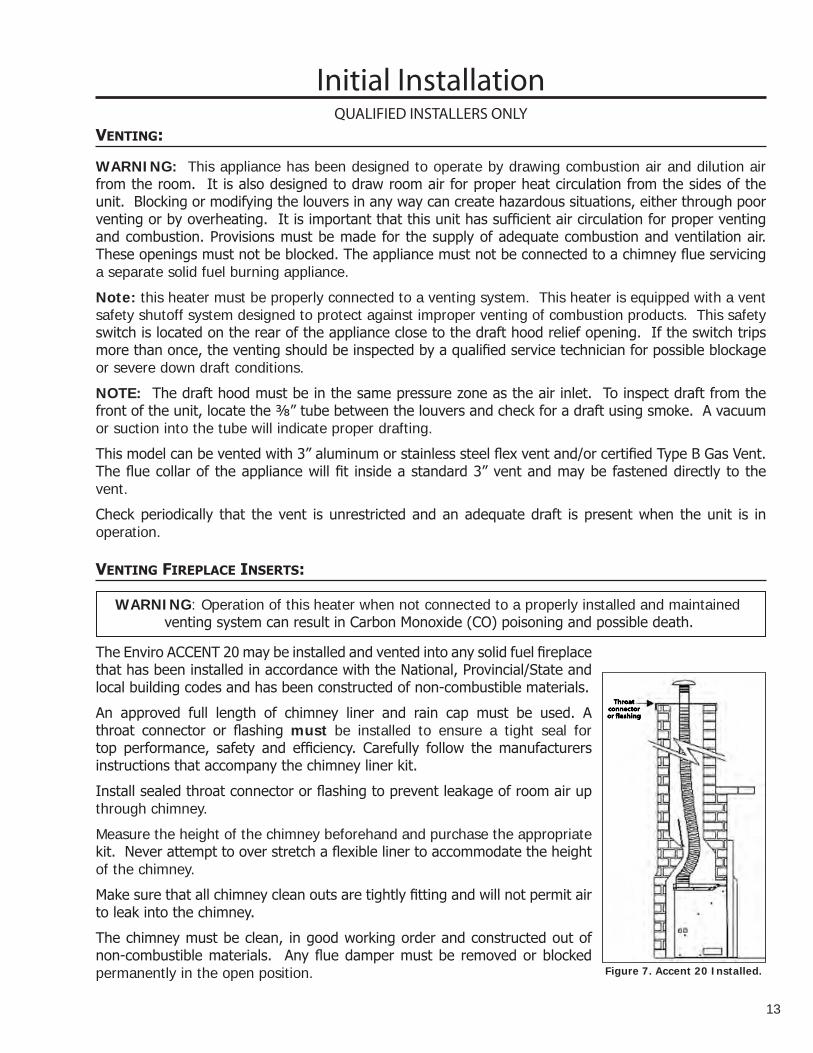
Throatconnectoror flashing
Figure 7. Accent 20 Installed.
The Enviro ACCENT 20 may be installed and vented into any solid fuel fireplace that has been installed in accordance with the National, Provincial/State and local building codes and has been constructed of non-combustible materials.
An approved full length of chimney liner and rain cap must be used. A throat connector or flashing must be installed to ensure a tight seal for top performance, safety and efficiency. Carefully follow the manufacturers instructions that accompany the chimney liner kit.
Install sealed throat connector or flashing to prevent leakage of room air up through chimney.
Measure the height of the chimney beforehand and purchase the appropriate kit. Never attempt to over stretch a flexible liner to accommodate the height of the chimney.
Make sure that all chimney clean outs are tightly fitting and will not permit air to leak into the chimney.
The chimney must be clean, in good working order and constructed out of non-combustible materials. Any flue damper must be removed or blocked permanently in the open position.

14
Remove the vent collar plate from the top of the insert. It is recommended that a bead of Mil-Pac is placed on the outer edge of the inner exhaust pipe (non-flared end) before it is connect securely to the vent collar with sheet metal screws and/or hose clamps. Check for any tears in the liner at this point.
IMPORTANT: The screws that hold the vent collar plate in its approved position must be installed.
gas line ConneCtion:
Warning: Only persons licensed to work with gas piping may make the necessary gas connections to this appliance.
Gas Line Connection:
• This fireplace is equipped with a certified flexible pipe located on the right side of the unit, terminating in a ⅜ inch male NPT fitting. Consult the local authorities for local codes or use the CAN/CGA B149 (1 or 2) installation code in Canada. In the US, gas installations follow either local codes or the current edition of the National Fuel Gas Code ANSI Z223.1.
• The efficiency of this unit is a product thermal efficiency rating determined under continuous operating conditions and was determined independently of any installed system.
The appliance and its shut-off valves must be disconnected from the gas supply piping system during any pressure testing where the pressure exceeds ½ psig (3.45 kPa) or the valve will be damaged.
The unit must be isolated from the gas supply piping system by closing its individual manual shut off valve during any pressure testing of the gas supply piping system at pressures equal to or less than ½ psig (3.45 kPa)
Always check for gas leaks with a soap and water solution after completing the required pressure test.
Main Burner Natural Gas(inch WC/KPa)
Propane Gas(inch WC/KPa)
Orifice: #45 DMS #55 DMS
Manifold Press: 3.8 / 0.95 11.0 / 2.74
Min. Manifold Press: 1.1 / 0.27 2.7 / 0.67
Max. Supply Press: 7.0 / 1.74 12.0 / 2.98
Min. Supply Press: 5.0 / 1.25 11.5 / 2.86
Max. BTU/hr Input: 20,000 (5.9 KW•h) 20,000 (5.9 KW•h)
Min. BTU/hr Input: 10,000 (2.9 KW•h) 10,000 (2.9 KW•h)
Output BTU/hr (fan on) 15,100 (4.24 KW•h) 15,400 (4.5 KW•h)
Output BTU/hr (fan off) 14,000 (4.1 KW•h) 14,400 (4.2 KW•h)
OLIT P
TP TH
TP TH
IN OUT
HI LO
N
OF
O
F
LIP
TO
Manifold Pressure Tap
Inlet Pressure Tap
Hi/Low Knob
Pilot Adjustment Screw
Gas Control Knob
Figure 8. Gas Control Assembly
Initial InstallationQUALIFIED INSTALLERS ONLY
TO TEST VALVE PRESSURES:
The pressure taps are located on the top right of the valve. Figure 11. • Turn set screw 1 turn counterclockwise
to loosen.• Place 5/16 inch (8 mm) I.D. hose over the
pressure taps.• Check pressures using a manometer.• When finished, release pressure, remove
hose and tighten set screw.
NEVER USE AN OPEN FLAME FOR LEAK TESTING.
Table 1: Gas Rating
Initial InstallationQUALIFIED INSTALLERS ONLY
eleCtriCal system: The fireplace must be electrically connected and grounded in accordance with local codes or, in the absence of local codes, with the current CSA C22.1 CANADIAN ELECTRICAL CODE Part 1, SAFETY STANDARDS FOR ELECTRICAL INSTALLATIONS, OR THE NATIONAL ELECTRICAL CODE ANSI / NFPA 70 in the US.
WARNING: The electrical grounding instructions must be followed. This appliance is equipped with a three-prong (grounding) plug for your protection against shock hazard, and should be plugged directly into a properly grounded three-prong outlet. DO NOT cut or remove the grounding prong from this plug.
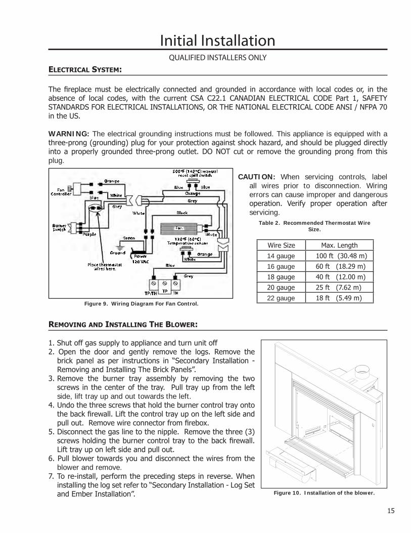
Figure 9. Wiring Diagram For Fan Control.
CAUTION: When servicing controls, label all wires prior to disconnection. Wiring errors can cause improper and dangerous operation. Verify proper operation after servicing.
120oF (60oC)Temperature sensor
300oF (149oC) manualreset spill switch
THTPTP/TH
Power120 VAC
Fan
Place thermostatwires here.
Purple
Black
Green
Ground
FanController
BurnerSwitch
Blue
Blue
BlueBlue
Grey
GreyGrey
White
White
White
White
Orange
Orange
Orange
Figure 10. Installation of the blower.
removing anD installing the blower:
1. Shut off gas supply to appliance and turn unit off2. Open the door and gently remove the logs. Remove the
brick panel as per instructions in “Secondary Installation - Removing and Installing The Brick Panels”.
3. Remove the burner tray assembly by removing the two screws in the center of the tray. Pull tray up from the left side, lift tray up and out towards the left.
4. Undo the three screws that hold the burner control tray onto the back firewall. Lift the control tray up on the left side and pull out. Remove wire connector from firebox.
5. Disconnect the gas line to the nipple. Remove the three (3) screws holding the burner control tray to the back firewall. Lift tray up on left side and pull out.
6. Pull blower towards you and disconnect the wires from the blower and remove.
7. To re-install, perform the preceding steps in reverse. When installing the log set refer to “Secondary Installation - Log Set and Ember Installation”.
Wire Size Max. Length
14 gauge 100 ft (30.48 m)
16 gauge 60 ft (18.29 m)
18 gauge 40 ft (12.00 m)
20 gauge 25 ft (7.62 m)
22 gauge 18 ft (5.49 m)
Table 2. Recommended Thermostat Wire Size.
15

Secondary Installationlog set anD ember installation: The placement of the logs is not arbitrary. If they are positioned incorrectly, the flames can be “pinched” and will not burn correctly. The burner (shown in Figure 11), and a few of the
Figure 11. Empty firebox with grate and locator pins.
Placement pins for Back Log
Figure 11: This is how the fire box looks with only the brick panels in place. This points out the two (2) placement pins for the back log on the burner.
Figure 12: The first log to be placed is the back log, it has two (2) placement pins. Note: The back log may fit tight against the back of the firebox.
Figure 13: The left log has two (2) placement pins.
Figure 12. First Stage Log Set Installation.
Figure 13. Second Stage Log Set Installation.
16
logs come with placement pins, notches and ledges, which make alignment easier. Using the pictures provided, carefully set the logs in place (see Figures 12 through 16).
NOTE: The logs are fragile and should be handled gently.
17
Secondary Installation
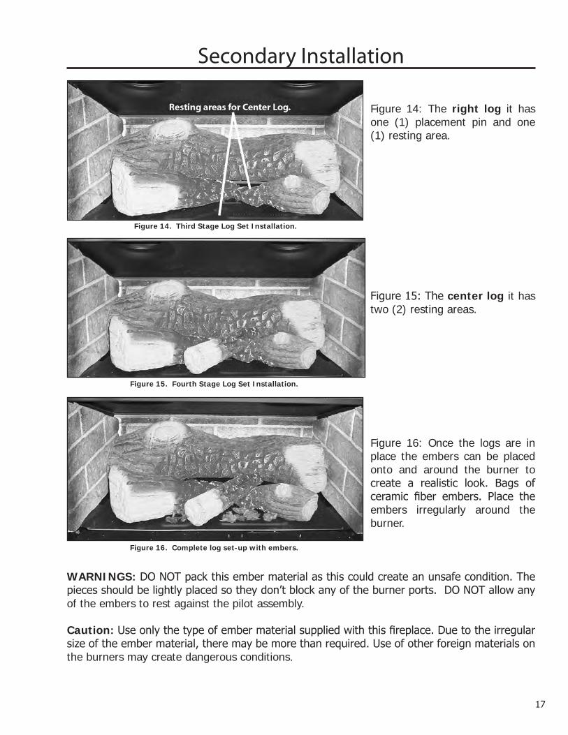
Figure 14. Third Stage Log Set Installation.
Figure 15. Fourth Stage Log Set Installation.
Figure 14: The right log it has one (1) placement pin and one (1) resting area.
Figure 15: The center log it has two (2) resting areas.
Figure 16: Once the logs are in place the embers can be placed onto and around the burner to create a realistic look. Bags of ceramic fiber embers. Place the embers irregularly around the burner.
Figure 16. Complete log set-up with embers.
WARNINGS: DO NOT pack this ember material as this could create an unsafe condition. The pieces should be lightly placed so they don’t block any of the burner ports. DO NOT allow any of the embers to rest against the pilot assembly.
Caution: Use only the type of ember material supplied with this fireplace. Due to the irregular size of the ember material, there may be more than required. Use of other foreign materials on the burners may create dangerous conditions.

Figure 17. Accent 20 complete log set-up with embers burning.
Figure 17: The Accent 20 burning with a good flame.NOTE: While the glass is still removed, it is recommended that the gas line be purged by lighting the pilot.
When lighting the fireplace for the first time since the log set and embers have been installed/replaced, watch for ignition at ALL the burner ports. If a long delay is noticed, turn the appliance off and wait for it to cool down. Then remove the glass and rearrange the ember material, making sure none of the burner ports are blocked.IMPORTANT NOTE RE FIRST FIRE UP: When the unit is turned on for the first time, it should be turned to high without the fan for the first 4 hours. This will cure the paint, logs, gasket material and the other products used in the manufacturing process. It is advisable to open a window or door, as the unit will start to smoke and can irritate some people. After the unit has gone through the first burn, turn the unit off including the pilot, let the unit cool then remove the glass door and clean it with a good gas fireplace glass cleaner, available at your local ENVIRO dealer
Maintenance: Once a year, the logs should be removed and checked for deterioration or large amounts of soot. A small amount on the bottom side of the logs is normal. Remove and replace the logs in the same manner described above. If new/more embers and rock wool is required, contact your nearest ENVIRO dealer.Never operate the fireplace with the glass door removed.
removing anD installing the briCk Panels:
Secondary Installation
The Accent 20 comes with the brick panel set pre-installed but for some maintenance and installation procedures the panels must be removed.
1. Use a ¼” socket or a flat head screwdriver to remove the brick panel brackets on either side of the top of the firebox (refer to Figure 18).
Figure 18: Brick panel bracket.
18

19
Quantity Description1 Surround panel extension
2 Small rectangular bracket
1 Left mounting bracket
1 Right mounting bracket
8 ¼” bolts
Figure 21. Assembly diagram of cast iron surround panel extension.
Please inspect all components for damage. If damage has occurred please contact the courier company, dealer, or distributor and have components repaired or replaced before installation.
INSTALL SURROUND PANEL EXTENSION TO THE TOP: Place the extension on top of the surround panel with the wider side facing up. Bolt the cast iron extension in place using the small rectangular brackets and eight ¼” bolts (four on each side) supplied with the extension.
INSTALL SURROUND PANEL EXTENSION TO THE BOTTOM: Place the extension under the surround panel with the widest side facing up. To bolt the extension onto the bottom the old mounting brackets on the panel have to be replaced with the new side mounting brackets and eight ¼” bolts (four on each side).
Secondary Installation
Cast iron surrounD Panel extension trim kit:
2. With the brackets removed the side panels can be taken out of the firebox. See Figure 19.
3. Remove back panel. See Figure 20.
To replace the panel set follow steps 1 through 3 in reverse order. Ensure the panels are flush against the back/sides of the firebox before installing the brackets.
Figure 20: Back brick panel.
Figure 19: Side and back brick panel.

Trouble ShootingProblem Possible Cause SolutionSpark will not light the pilot after repeatedly pressing the spark ignitor
Defective piezo ignitor • Check connections to ignitor.• If ignitor connections are good but no spark,
replace ignitor.Broken spark electrode • Check for broken ceramic insulation, replace
electrode if broken.Misaligned spark electrode • If spark is not arcing from electrode to pilot,
loosen the screws on the pilot base adjust and tighten.
Pilot will not remain lit Problem with thermocouple circuit
• Check for proper connection of the thermocouple to the rear of the valve. If loose, fully tighten.
• Check pilot for full flame impingement around thermocouple. If flame is too small, check gas pressure, adjust pilot rate screw, check pilot head for damage.
• Check thermocouple voltage at valve. It must be greater than 5 mV. If low, replace thermocouple.
Air in gas line (pilot dies while knob is depressed)
• Bleed line.• Check gas line pressure.• Contact dealer.
Burners will not remain lit
Problem with thermopile circuit
• Check gas line pressure .• Check for flame impingement on thermopile. If
low, see “Pilot will not remain lit”.• Check thermopile for minimum of 200 mV when
burner is switched on.• Check wiring to thermostat for breaks.
Flame lifting Leak in vent pipe • Check for leaks in vent connections.Improper vent configuration • Check vent configuration with manual.Terminal may be recirculating flue gases
• Check to see if terminal is on correctly.• May need to install high wind termination cap.• Contact dealer.
Glass fogs up Normal Condition: after the appliance warms up the glass will clear.**Due to additives in gas, glass may get hazy during operation** Clean as needed.
Blue Flames Normal during start up: flames will yellow as the fireplace heats up.Flames are burning “dirty” or sooting
Flame impingement • Check log positioning.• Increase primary air by opening the venturi
shutter and/or by opening the vent restrictor.See also “Burners will not remain lit.”
Insufficient air for combustion.
Air tight house or a vacuum in room due to other air moving devices (eg. kitchen and bathroom fans).
• Supply make-up air to the unit, open window.
20

21
Parts List - Cast
Reference Number
Part Description Part Number
Front & Complete Surround - Painted 50-146Front & Complete Surround - Antique White 50-147Front & Complete Surround - Diamond Black 50-148Front & Complete Surround - Pearl Grey 50-149Front & Complete Surround - Inferno Red 50-150Front & Complete Surround - Wedgewood Blue 50-151Front & Complete Surround - Westport Green 50-152Front & Complete Surround - Antique Chestnut 50-813Surround Panels Only - Painted 50-409Surround Panels Only - Antique White 50-410Surround Panels Only - Diamond Black 50-411Surround Panels Only - Inferno Red 50-412Surround Panels Only - Pearl Grey 50-413Surround Panels Only - Wedgewood Blue 50-414Surround Panels Only - Westport Green 50-415Surround Panels Only - Antique Chestnut 50-883
1 Surround Panels Top Piece Only - Painted 50-4161 Surround Panels Top Piece Only - Diamond Black 50-4171 Surround Panels Top Piece Only - Inferno Red 50-4181 Surround Panels Top Piece Only - Pearl Grey 50-4191 Surround Panels Top Piece Only - Antique White 50-4201 Surround Panels Top Piece Only - Wedgewood Blue 50-4211 Surround Panels Top Piece Only - Westport Green 50-4221 Surround Panels Top Piece Only - Antique Chestnut 50-8822 Surround Panels Left Piece Only - Painted 50-4232 Surround Panels Left Piece Only - Antique White 50-4242 Surround Panels Left Piece Only - Diamond Black 50-4252 Surround Panels Left Piece Only - Inferno Red 50-4262 Surround Panels Left Piece Only - Pearl Grey 50-4272 Surround Panels Left Piece Only - Wedgewood Blue 50-4282 Surround Panels Left Piece Only - Westport Green 50-4292 Surround Panels Left Piece Only - Antique Chestnut 50-880

Parts List - Cast
Reference Number
Part Description Part Number
3 Surround Panels Right Piece Only - Painted 50-4303 Surround Panels Right Piece Only - Antique White 50-4313 Surround Panels Right Piece Only - Diamond Black 50-4323 Surround Panels Right Piece Only - Inferno Red 50-4333 Surround Panels Right Piece Only - Pearl Grey 50-4343 Surround Panels Right Piece Only - Wedgewood Blue 50-4353 Surround Panels Right Piece Only - Westport Green 50-4363 Surround Panels Right Piece Only - Antique Chestnut 50-8814 Front Only (No glass, surround, valve door, or clip-on) - Painted 50-4374 Front Only (No glass, surround, valve door, or clip-on) - Antique White 50-4384 Front Only (No glass, surround, valve door, or clip-on) - Diamond Black 50-4394 Front Only (No glass, surround, valve door, or clip-on) - Inferno Red 50-4404 Front Only (No glass, surround, valve door, or clip-on) - Pearl Grey 50-4414 Front Only (No glass, surround, valve door, or clip-on) - Wedgewood Blue 50-4424 Front Only (No glass, surround, valve door, or clip-on) - Westport Green 50-4434 Front Only (No glass, surround, valve door, or clip-on) - Antique Chestnut 50-8795 Valve Access Door - Painted 50-4445 Valve Access Door - Antique White 50-4455 Valve Access Door - Diamond Black 50-4465 Valve Access Door - Inferno Red 50-4475 Valve Access Door - Pearl Grey 50-4485 Valve Access Door - Wedgewood Blue 50-4495 Valve Access Door - Westport Green 50-4505 Valve Access Door - Antique Chestnut 50-8846 Trim (1 piece) - Painted 50-1536 Trim (1 piece) - Antique White 50-1546 Trim (1 piece) - Diamond Black 50-1556 Trim (1 piece) - Pearl Grey 50-1566 Trim (1 piece) - Inferno Red 50-1576 Trim (1 piece) - Wedgewood Blue 50-1586 Trim (1 piece) - Westport Green 50-1596 Trim (1 piece) - Antique Chestnut 50-814
22

23
Parts Diagram - Cast
ACCENT 20 CASTJune 2004
2
1
6
3
6
4
5
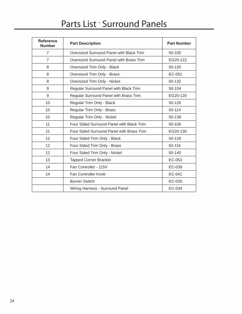
Parts List - Surround Panels
Reference Number Part Description Part Number
7 Oversized Surround Panel with Black Trim 50-105
7 Oversized Surround Panel with Brass Trim EG20-122
8 Oversized Trim Only - Black 50-120
8 Oversized Trim Only - Brass EC-051
8 Oversized Trim Only - Nickel 50-132
9 Regular Surround Panel with Black Trim 50-104
9 Regular Surround Panel with Brass Trim EG20-120
10 Regular Trim Only - Black 50-126
10 Regular Trim Only - Brass 50-114
10 Regular Trim Only - Nickel 50-138
11 Four Sided Surround Panel with Black Trim 50-106
11 Four Sided Surround Panel with Brass Trim EG20-130
12 Four Sided Trim Only - Black 50-128
12 Four Sided Trim Only - Brass 50-116
12 Four Sided Trim Only - Nickel 50-140
13 Tapped Corner Bracket EC-053
14 Fan Controller - 115V EC-039
14 Fan Controller Knob EC-041
Burner Switch EC-026
Wiring Harness - Surround Panel EC-034
24

25
Parts Diagram - Surround Panels
Accent 20 InsertSurround PanelJune 2004
10
9
7
8
11
12
14
13

Parts List - ComponentsReference Number Part Description Part Number
Door Louvre Magnets 30-037Window Frame Nut Inserts 30-038Window Frame Screws 30-039
15 Door Cover - Gold 50-00115 Door Cover - Polished Nickel 50-002
Accent 20 Owner’s Manual 50-30416 Blank Orifice #73 50-34317 120°F (49°C) Ceramic Fan Temperature Sensor EC-00118 300°F (149°C) Temperature Sensor Spill Switch EC-00319 S.I.T. Nova Valve NG (50% Turn Down) EC-00619 S.I.T. Nova Valve LP (50% Turn Down) EC-00720 Thermocouple EC-00920 Spark Electrode with Ignitor Cable EC-01120 Thermopile EC-01220 Fully Assembled Pilot NG EC-01520 Fully Assembled Pilot LP EC-01621 S.I.T. Piezo Ignitor EC-02322 Fan Mount EC-028
Wiring Harness Complete (3 Pieces) EC-033Wiring Harness - Body EC-035Wiring Harness - Burner EC-036Domestic Power Cord - 115V EC-042Heyco Strain Relief EC-044Embers (Coal & Wool) EC-046Log Set with Embers EC-048Insert Valve Access Door Magnets (x 2) EC-050
23 Convection Blower - 115V EC-069NG Burner Control Assembly EG20-052LP Burner Control Assembly EG20-054
24 3” X ⅜” Black Iron Nipple EG20-06225 Burner Tray Top EG20-066
Envirogas EG20 Name Plate EG20-07026 Brick Panel - Ceramic EG20-07426 Brick Panel - Metal EG20-07527 Window Channel Tape EG20-08927 Glass with Gasket EG20-090
Clip-On Door EG20-09128 Door - Painted EG20-09229 Door Complete - Painted EG20-093
Bevelled Fascia EG20-11130 Louvre Set (Top & Bottom) - Gold EG20-11530 Louvre Set (Top & Bottom) - Painted EG20-116
LP to NG Conversion Kit EG20-201NG to LP Conversion Kit EG20-203
26

27
Parts Diagram - Components
Accent 20 Insert
Com
ponentsJune 2004
18
22
1617
23
1921
30
2625
202427
28 29
15

WarrantySherwood Industries Ltd. offers a *Lifetime Warranty on this gas product. The lifetime warranty covers the appliance for a period of seven years from the date of installation. This warranty applies only to the original owner in the original location.
Covered under the lifetime warranty are Cabinet Sides, Tops, Pedestals, Surround Panels, Chassis and Heat Exchanger. These steel components are covered against manufacturer’s defects for parts 5 years labor for the first year and for parts only thereafter† The following exclusions apply: over-firing due to incorrect setup or tampering, damage caused by incorrect installation, usage or abuse. The unit must be properly installed by a qualified technician or installer, and must meet all local and national gas and building code requirements.
We also cover the following against manufacture defects under our lifetime warranty: Gold Plating, Log Set, Burners and Glass†. The following exclusions apply: Gold plating- Damage caused by scratching, marring, chemicals, fingerprints, abrasive cleaners or discoloration with age. Glass- use of harsh or abrasive cleaners, striking the glass or surface contaminants. Log set- Damage caused by incorrect handling or misuse. Burners- damage caused by improper or continuous operation under incorrect conditions.
Sherwood Industries Ltd. offers a 2-year warranty on all the Electrical Components and Gas Components against manufacturing defects. Paint is covered against flaking. This offer includes parts and labor for 1 year and for parts only thereafter.
The paint on the Metal Brick Liner may peel. This is due to the extreme conditions applied to the paint and is not covered under warranty.
Your dealer shall make all claims under this warranty in writing.
† - TO A MAXIMUM OF SEVEN YEARS
WHEN FILING A WARRANTY CLAIM PLEASE COMPLETE THE FOLLOWING INFORMATION ON AN OFFICIAL WARRANTY CLAIM FORM:
To the Dealer• Name, address and telephone number of purchaser and date of purchase.• Date of installation. Name of installer and dealer. Serial number of the appliance. Nature of complaint, defects or malfunction, description and part # of any parts replaced.
To the Distributor• Sign and verify that work and information are correct.
This warranty covers defects in materials and workmanship only if the product has been installed according to the manual’s instructions. If the product is damaged or broken as a result of misuse or mishandling the warranty does not apply. The warranty does not cover removal and re-installation costs.
Sherwood Industries Ltd. reserves the right to repair or to replace the defective product. The shipping costs are to be paid by the consumer. All warranties by the manufacturer are set forth herein and no claim shall be made against the manufacturer on any oral warranty or representation.
Sherwood Industries Ltd. and its employees or representatives will not assume any damages, either directly or indirectly caused by improper usage, operation, installation, servicing or maintenance of this appliance.
Sherwood Industries Ltd. reserves the right to make changes without notice. Please complete and mail the warranty registration card and have the installer fill in the installation data sheet in the back of the manual for warranty and future reference.
28

29
Installation Data SheetThe following information must be recorded by the installer for warranty purposes and future reference.
NAME OF OWNER:
_________________________________________
ADDRESS:
_________________________________________
_________________________________________
_________________________________________
PHONE:___________________________________
NAME OF DEALER:
_________________________________________
ADDRESS:
_________________________________________
_________________________________________
_________________________________________
PHONE:___________________________________
MODEL:___________________________________
SERIAL NUMBER:___________________________
DATE OF PURCHASE: _____________ (dd/mm/yyyy)
DATE OF INSTALLATION:___________(dd/mm/yyyy)
� NATURAL GAS (NAT) � PROPANE(LPG)
INLET GAS PRESSURE:_________in wc
MAIN BURNER ORIFICE:__________# DMS
PILOT ORIFICE #_________OR________in diam.
INSTALLER’S SIGNATURE:
_________________________________________
NAME OF INSTALLER:
_________________________________________
ADDRESS:
_________________________________________
_________________________________________
_________________________________________
PHONE:___________________________________
MANUFACTURED BY:SHERWOOD INDUSTRIES LTD.
6782 OLDFIELD RD. SAANICHTON, BC, CANADA V8M 2A3www.envirofire.biz
June 14, 2004C-10235