by christopher mark wilson
TRANSCRIPT
MODELING AND MITIGATION FOR HYBRID SPACE COMPUTERS
By
CHRISTOPHER MARK WILSON
A DISSERTATION PRESENTED TO THE GRADUATE SCHOOL
OF THE UNIVERSITY OF FLORIDA IN PARTIAL FULFILLMENT
OF THE REQUIREMENTS FOR THE DEGREE OF
DOCTOR OF PHILOSOPHY
UNIVERSITY OF FLORIDA
2018

© 2018 Christopher Mark Wilson

To my family for all their support, and especially Dave for not letting me make bad decisions.

4
ACKNOWLEDGMENTS
This research was funded by industry and government members of the National Science
Foundation (NSF) Center for Space, High-performance and Resilient Computing (SHREC),
formerly known as the Center for High-performance Reconfigurable Computing (CHREC) and
its I/UCRC Program under Grant Nos. IIP-1161022 and CNS-1738783. The author thanks Alan
George as co-author and advisor for all the dissertation research.
For extensive contributions for the success of the STP-H5/CSP mission the authors wish
to especially thank Dylan Rudolph and Jacob Stewart (PCB design), Patrick Gauvin (flight
software), James MacKinnon (instrument design), Antony Gillette (ground-station development),
Darlene Brown (procurement), Alex Wilson, Aaron Stoddard, and Dr. Mike Wirthlin (scrubbing
and radiation testing), Gary Crum (systems engineering support) and Tom Flatley (mission
design).
More than a dozen students contributed heavily to the hardware and software
development of CSPv1 and to the STP-H5/CSP mission. Special thanks to James Coole, Ed
Carlisle, Bryant Cockcroft, Sebastian Sabogal, Daniel Sabogal, Jonathan Urriste, Dorothy Wong,
Brad Shea, Christopher Morales, Andy Wilson, Jordan Anderson, Ryan Zavoral, Rainer
Ledesma, Travis Wise, Jay Wang, Joe Kimbrell, and Dr. Herman Lam for their contributions.
We also wish to thank all the additional support received from NASA Goddard for software
development, environmental testing, mechanical design, and design reviews. This group includes
Elizabeth Timmons, Jaclyn Beck, Alessandro Geist, Keven Ballou, Dave Petrick, Mike Lin,
Allison Evans, Matt Colvin, Eric Gorman, Tracy Price, Curtis Dunsmore, and Katie Brown. We
would also like to thank the operations support provided by STP, specifically Robert Plunkett,
Zachary Tejral, and William Lopez. Finally, we’d like to thank Brandon Reddell and Kyson

5
Nguyen of NASA JSC’s EV511 group for supporting the expensive heavy-ion radiation tests at
BNL.
For assistance in the development of the hybrid modeling methodology, the author
wishes to thank Ben Klamm, Jacob Stewart, Ed Carlisle, and Pete Sparacino for their expertise
and input toward developing this methodology. In addition, we would like to thank Nick Wulf,
Dr. Ann Gordon-Ross, Dr. Michael Wirthlin, Alex Wilson, Dan Espinosa, and Dave Petrick for
their support and review. Finally, we would like to thank Mike Campola, Ray Ladbury, and Ken
LaBel of NASA Goddard Code 561 for input, feedback, and review.
For assistance in development of the new hybrid, fault-tolerant framework, the author
wishes to thank Sebastian Sabogal for extensive FPGA development and extending the work in
future papers. Additionally, the author thanks Jason Gutel for preliminary AMP development,
Adam Jacobs for guidance and knowledge related to RFT, Ed Carlisle for assistance in simple
verification experiments, David Wilson for initial prototype studies, and Tyler Lovelly and Andy
Milluzzi for providing device metrics for the Zynq and MicroBlaze. The author thanks John
McDougall at Xilinx for providing BSPs for AMP.
The author also gratefully acknowledges donations and support from the following
vendors and organizations that helped make this work possible: Xilinx for development licenses
and web ticket support; Intersil, Texas Instruments, Microsemi Corporation, Cobham, and e2V
for supplying key components that comprise the designs; and Department of Energy and Cisco
for supporting the LANSCE and TRIUMF radiation tests, respectively.

6
TABLE OF CONTENTS
page
ACKNOWLEDGMENTS ...............................................................................................................4
LIST OF TABLES .........................................................................................................................10
LIST OF FIGURES .......................................................................................................................11
ABSTRACT ...................................................................................................................................14
CHAPTER
1 INTRODUCTION ..................................................................................................................16
2 BACKGROUND RESEARCH ..............................................................................................21
Space-Radiation Environment ................................................................................................21
Radiation Mitigation Programs and Processes .......................................................................22 Radiation Hardness Assurance (RHA) ............................................................................23 Single-Event Effects Criticality Analysis (SEECA) .......................................................24
NASA Electronic Parts and Packaging (NEPP) Program ...............................................24 Example NASA CubeSat Part Selection Process ............................................................24
Reliability Modeling ...............................................................................................................26 Probabilistic Risk Assessment and Fault-Tree Analysis .................................................26
Dynamic Computer Fault Tree and Markov Models ......................................................27 Types of Computing ...............................................................................................................29
Reconfigurable Computing .............................................................................................29 Hybrid Computing ...........................................................................................................31
Fault-Tolerant Strategies ........................................................................................................32
Symmetric and Asymmetric Multiprocessing (SMP / AMP) ..........................................34 Lockstep Operation .........................................................................................................36 Reconfigurable Fault Tolerance (RFT) ...........................................................................36
Radiation Tolerant SmallSat (RadSat) Computer System ...............................................37 Space Test Program Houston-5 (STP-H5) .............................................................................38
Space Test Program .........................................................................................................39 ISS SpaceCube Experiment Mini (ISEM) .......................................................................39
3 SMALL SPACECRAFT COMPUTING ................................................................................42
SmallSats and CubeSats Overview .........................................................................................42 SmallSat Technology State of the Art ....................................................................................44
SmallSat Computing vs. Traditional Spacecraft Computing ..................................................46 Challenges to SmallSat Computing ........................................................................................48 Better Computing with Hybrid Approach ..............................................................................50
4 CONCEPTS OF HYBRID, RECONFIGURABLE SPACE COMPUTING .........................51

7
5 RELIABILITY METHODOLOGY FOR SMALLSAT COMPUTERS ...............................53
Methodology Stages ...............................................................................................................54
Stage 1: Component Analysis .........................................................................................54 Stage 2: Radiation Data Collection .................................................................................54 Stage 3: Mission and Model Parameter Entry .................................................................57 Stage 4: Fault-Tree Construction, Iteration, and Modification .......................................58 Mitigation Guidelines ......................................................................................................65
CSPv1 Analysis ......................................................................................................................66 Case Study: Description and Assumptions .....................................................................66 Case Study: Results and Analysis ..................................................................................67
Methodology Insights and Improvements ..............................................................................70
6 CSPv1 DESIGN......................................................................................................................72
Hardware Architecture ............................................................................................................72 Software Design ......................................................................................................................76
Fault-Tolerant Computing Options.........................................................................................77 Design Revisions ....................................................................................................................79
7 PERFORMANCE ANALYSIS OF CSPv1 ............................................................................80
8 RELIABILITY ANALYSIS OF CSPv1 ................................................................................83
Radiation Testing Results .......................................................................................................83
Neutron Testing ...............................................................................................................83
Brookhaven National Laboratory October 2015 Radiation Test .....................................84 Brookhaven National Laboratory October 2016 Radiation Test .....................................85
Radiation Environment Upset Prediction ...............................................................................86
Workmanship Reliability ........................................................................................................87
9 HIGHLIGHTS OF STP-H5/CSP MISSION EXPERIMENT ................................................89
Mission Configuration ............................................................................................................90
Hardware .........................................................................................................................90 Software ...........................................................................................................................90 Ground Station .................................................................................................................92
Primary Mission Objectives ...................................................................................................92
Secondary Mission Objectives ...............................................................................................93 Autonomous Operations ..................................................................................................93 In-Situ Upload Capability ................................................................................................94
Partial Reconfiguration ....................................................................................................94 Space Middleware ...........................................................................................................95 Device Virtualization and Dynamic Synthesis ................................................................96
Preliminary On-Orbit Results .................................................................................................99
10 FAULT-TOLERANT FRAMEWORK FOR HYBRID DEVICES .....................................101
8
HARFT Use-Case and Design Overview .............................................................................101
Flight Example ..............................................................................................................101
HARFT Hardware Architecture ....................................................................................102 Hard-Processing System (HPS) .............................................................................102 Soft-Processing System (SPS) ...............................................................................103
Configuration Manager (ConfigMan) ...........................................................................103 ConfigMan Scrubbing ...................................................................................................104
ConfigMan mode-switching mechanics .................................................................105 ConfigMan mode switching process ......................................................................105
SPS Static Logic ............................................................................................................105 Fault-Tolerant mode switching ..............................................................................106 Mode switching ......................................................................................................107
Challenges ..............................................................................................................107
Flight configuration and use model ........................................................................108 Experiments and Results .......................................................................................................108
Processor Experiments ..................................................................................................108
Basic SMP experiment ...........................................................................................109 Basic AMP experiment ..........................................................................................109
Reliability Modeling ......................................................................................................109
CRÈME96 ..............................................................................................................110 Modeling methodology ..........................................................................................110
HARFT Prototype Description ......................................................................................110 HPS configuration ..................................................................................................110 SPS configuration ...................................................................................................111
ConfigMan configuration .......................................................................................111
Additional hardware configuration ........................................................................111 HARFT Prototype Analysis ..........................................................................................113 HARFT Performance Modeling ....................................................................................115
Framework Status and Future Considerations ......................................................................117
11 CSP SUCCESSORS .............................................................................................................119
µCSP and Smart Modules .....................................................................................................119
Concepts of Smart Modules ..........................................................................................119 µCSP Hardware Architecture ........................................................................................123 µCSP Software Architecture .........................................................................................125 µCSP Fault-Tolerant Architecture .................................................................................126
Smart Module Designs ..................................................................................................127 µCSP Achievement Highlights .....................................................................................129
SuperCSP and STP-H6/SSIVP .............................................................................................129
CSPv2 ...................................................................................................................................132
12 CONCLUSIONS ..................................................................................................................133

9
APPENDIX
SPACE PROCESSORS ........................................................................................................135
LIST OF REFERENCES .............................................................................................................137
BIOGRAPHICAL SKETCH .......................................................................................................145
10
LIST OF TABLES
Table page
5-1 SEU upset rates for non-volatile memory reported by CREME96....................................58
5-2 Typical TID amounts for LEO with 1-year mission reported by SPENVIS .....................58
5-3 Yearly TID by orbit. ..........................................................................................................67
5-4 Estimated board lifetime. ...................................................................................................68
5-5 CSPv1 board upset rate. .....................................................................................................69
5-6 Power system upset/day. ....................................................................................................70
6-1 Xilinx Zynq-7020 ARM specifications. ............................................................................73
6-2 Xilinx Zynq-7020 FPGA specifications ............................................................................73
6-3 CSPv1 Rev. B power consumption. ...................................................................................75
7-1 Computational density and computational density per Watt of popular rad-hard
processors and the Zynq.....................................................................................................81
7-2 CoreMark benchmarking. ..................................................................................................82
9-1 CSP Board Upset Rate. ....................................................................................................100
10-1 PRR resource utilization. .................................................................................................112
10-2 Prototype total resource utilization. .................................................................................112
10-3 FPGA scrubbing duration. ...............................................................................................115
10-4 Computational density device metrics. ............................................................................115
10-5 Zynq processors’ CoreMark benchmarking performance. ..............................................116
11-1 Example components for Smart Modules ........................................................................122
11-2 Major components of µCSP. ............................................................................................124
11-3 SmartFusion2 ARM specifications. .................................................................................125
11-4 SmartFusion2 FPGA specifications .................................................................................125
A-1 SmallSat processors and Single-Board Computers..........................................................135

11
LIST OF FIGURES
Figure page
1-1 SpaceWorks Historical Nano/Microsatellite Launches. ....................................................18
2-1 Simplified fault-tree example in NASA’s Fault-Tree Handbook. .....................................26
2-2 Simple DFT and its equivalent, complex, and large Markov model representation
demonstrating state explosion by Boudali et al. ................................................................28
2-3 ARM processing-configuration illustrations......................................................................35
2-4 Lockstep Operation. ...........................................................................................................36
2-5 RFT Architecture Diagram. ...............................................................................................37
2-6 RadSat FPGA Architecture Layout with Partial Reconfiguration Regions. ......................38
2-7 STP-H5/ISEM flight box 3D model. .................................................................................40
2-8 STP-H5/ISEM fully integrated payload. ............................................................................41
2-9 STP-H5/ISEM card block diagram. ...................................................................................41
3-1 Performance scaled by power comparison of onboard processors. ...................................47
3-2 Costs of commercially available SBCs. .............................................................................48
5-1 Reliability methodology stages. .........................................................................................53
5-2 Statistical structure of representative data. ........................................................................56
5-3 Example cross section vs. LET graph ................................................................................57
5-4 Basic event for a SEU to memory cell in non-volatile memory from heavy ions or
trapped protons...................................................................................................................60
5-5 System-level fault tree with key modules for analysis. .....................................................61
5-6 Expanded memory module. ...............................................................................................61
5-7 Expanded non-volatile memory section.............................................................................63
5-8 Non-volatile memory module with ECC. ..........................................................................64
5-9 Graph generated by Windchill Predictions for case study board failure. ..........................65
5-10 LEO and GEO reliability curves. .......................................................................................69
12
5-11 Power module reliability. ...................................................................................................70
6-1 CSPv1 Rev B. block diagram. ...........................................................................................73
6-2 CSPv1 designs ...................................................................................................................74
6-3 CSPv1 Rev. B mated to Evaluation Boards. ......................................................................76
8-1 CSP at test facilities. ..........................................................................................................85
9-1 STP-H5 Pallet 3D-view and integrated-for-flight system .................................................89
9-2 STP-H5/CSP flight unit. ....................................................................................................89
9-3 CLIF OpenCL Framework. ................................................................................................97
9-4 Example image products from STP-H5/CSP. ....................................................................99
10-1 World Map displaying proton flux at South Atlantic Anomaly. .....................................102
10-2 HARFT architecture diagram ..........................................................................................103
10-3 ConfigMan and SPS-SL architecture diagram. ................................................................106
10-4 Illustrated fault-tolerant modes diagram. .........................................................................106
10-5 FPGA configuration area in floorplan view.....................................................................112
10-6 HARFT reliability with L2 cache disabled. .....................................................................113
10-7 HARFT reliability with L2 cache enabled. ......................................................................114
10-8 Upsets per day vs. performance with L2 cache disabled. ................................................117
10-9 Upsets per day vs. performance with L2 cache enabled ..................................................117
11-1 Example template for Smart Module. ..............................................................................120
11-2 Integration and mating with a Smart Module. .................................................................121
11-3 Ring network connection for Smart Module. ..................................................................122
11-4 µCSP computer board testing prototype. .........................................................................123
11-5 Example of 6U CubeSat wiring harness. .........................................................................128
11-6 SuperCSP backplane with 4 CSPv1s. ..............................................................................130
11-7 Deconstructed view of STP-H6/SSIVP flight box...........................................................131

13
11-8 Fully assembled flight box for environmental testing. ....................................................132

14
Abstract of Dissertation Presented to the Graduate School
of the University of Florida in Partial Fulfillment of the
Requirements for the Degree of Doctor of Philosophy
MODELING AND MITIGATION FOR HYBRID SPACE COMPUTERS
By
Christopher Mark Wilson
May 2018
Chair: Alan Dale George
Major: Electrical and Computer Engineering
Space is a hazardous environment for electronic systems, therefore, the traditional
approach to space computing relies upon radiation-hardened electronics, which are
characteristically more expensive, larger, less energy-efficient, and generations behind in
performance and functionality of modern commercial processors. Conversely, modern
commercial processors, while providing the utmost in performance and energy-efficiency, are
susceptible to space radiation. The desire for more autonomous missions combined with growing
demands for more detailed products from advanced sensors, have challenged organizations to
stay relevant by “doing more with less” to meet future requirements. To meet this need,
researchers at the National Science Foundation Center for High-Performance Reconfigurable
Computing have developed a new design concept in hybrid space computing that features fixed
and reconfigurable processor architectures merged with innovative system design that is a
combination of three technologies: commercial devices; radiation-hardened components; and
fault-tolerant computing.
To model the reliability of these new hybrid designs a novel methodology was developed
for estimating reliability of space computers for small satellites from the system-level
perspective. This methodology is useful in scenarios where funding, time, or experience for

15
radiation testing are scarce. The output values of the method can then be used to build a first-
order estimate on how well the system performs given specific mission-environment conditions.
Additionally, due to the complexity of including a hybrid-processor architecture within a system
design, a new fault-tolerant technique was developed to provide and evaluate tradeoffs in system
reliability, performance, and resource utilization. This fault-tolerant computing strategy accounts
for the hybrid nature of a device and suggests a strategy that works cooperatively between both
types of architectures.
The hybrid space computing concept has culminated in development of several novel
research platforms, most significantly the CSPv1 flight computer, which was successfully
deployed on the International Space Station. Prior to flight, this CSPv1 design was analyzed and
tested on the ground with the new reliability methodology and radiation tests. Recent in-flight
data has validated the design, and shown that CSPv1 exceeds reliability expectations predicted
by models. The new fault-tolerant computing strategy was developed for CSPv1 specifically, and
will be deployed on CSPv1 in future missions.
16
CHAPTER 1 INTRODUCTION
Future spacecraft technology will be defined by emphasizing the importance of creating
highly reliable and more affordable space systems. Prohibitive launch costs and increasing
demands for higher computational performance have promoted a rising trend towards
development of smaller spacecraft featuring commercial technology on higher-risk missions and
less-stringent standards as exemplified by NASA Ames Research Center’s Phonesat mission [1]
and a survey of small spacecraft technology by Allman and Petro [2]. Enabled by these
advancements, it is now feasible for a group of small satellites (SmallSats) to perform the same
mission tasks that would have required a costly, massively sized satellite in the past. This
concept has been extensively studied for different missions [2-3]. The growing importance of
SmallSat missions has been gestating as a future outcome from as early as 2000, as described by
the National Research Council’s (NRC) publication “The Role of Small Satellites in NASA and
NOAA Earth Observation Programs,” [4] and has been now burgeoning in recent years. The
rationale dictated in this study for the advancement of SmallSats largely remains unchanged to
date from its original publication period. The study stressed the benefits of SmallSats, as low-
cost yet capable platforms offering great architectural and programmatic flexibility. Additionally,
the study highlighted unique design features that apply to SmallSats, such as distributed
functions, observation strategies (constellations and clusters), rapid infusion of technology, and
both budget and schedule flexibility.
The gradual progress and direction of spacecraft technology towards SmallSats can be
attributed to NASA’s response to the NRC’s decadal survey for Earth science. The decadal
survey focuses on the needs and priorities of the scientific community to plan on key space-
research areas and missions. In the midterm assessment [5] of the original 2007 survey [6], there

17
are two key findings that can be addressed with new processing capabilities for Small Satellites.
The first main finding: “The nation’s Earth observing system is beginning a rapid decline in
capability as long-running missions end and key new missions are delayed, lost, or canceled.”
This finding describes dwindling numbers of planned and funded, larger Earth
observation satellites. This shortcoming is problematic since Earth science needs more data to
sustain more powerful climate and weather models. A further concern is that next-generation
instruments generating more data will saturate satellite downlink bandwidth. Therefore, a
possible solution is to develop more small satellites that can perform onboard processing when
feasible to allow results to be transmitted in lieu of the entire data set.
Another major finding of the decadal survey: “Alternative platforms and flight
formations offer programmatic flexibility. In some cases, they may be employed to lower the
cost of meeting science objectives and/or maturing remote sensing and in situ observing
technologies.” The alternative platforms mentioned in the survey include small satellites that can
either act independently or work cooperatively to form a distributed science mission.
SmallSats, especially in the range of nano and micro satellites, have rapidly become more
advanced and have been featured in more missions in recent years. This growth has been
attributed to CubeSat (sub-class of SmallSat) research programs started by the National Science
Foundation (NSF), which has incited university participation and a growing commercial interest
from industry for using SmallSats in Earth observations and remote sensing. CubeSats have
become so popular largely due to “comparatively low development costs, miniaturized
electronics, and timely availability of affordable launch opportunities” [7]. Correspondingly, the
number of CubeSat launches has rapidly expanded. SpaceWorks, a company that focuses on
monitoring global satellite activities, publishes studies on its findings annually [8]. In Figure 1-1,

18
SpaceWorks highlights a sudden increase in SmallSats in the 1 to 50 kg range from 2000 until
2016, emphasizing major changes in the space development ecosystem.
Figure 1-1. SpaceWorks Historical Nano/Microsatellite Launches [8].
In 2015, NASA released a technology roadmap to describe the future development efforts
required to create novel, cutting-edge technologies that enable new capabilities for ambitious
future space missions [9]. In this roadmap, there are 15 distinct technology areas (Launch
Propulsion Systems, Science, Instruments, Observatories, Sensor Systems, etc.) relating to
different aspects that comprise space missions. Additionally, they note technology topics that
encompass and overlap multiple areas. One of these domain-crossing technology topics is
avionics, which focuses on the electronic systems that are essential to satellite capabilities.
In 2016, the NRC published a study [10] that investigated all the topics found in the
roadmap to provide recommendations of focus for NASA, ranking the topics in order of
importance, and classifying key topics as “high-priority.” 88 topics were classified as high-
priority technologies, and 26 of those 88 (roughly 30%) are encapsulated by avionics, further
highlighting the significance of computing and processing for space operations. SmallSats can

19
play a crucial role in advancing key technology roadmap topics through technology
demonstration of new computers and systems.
Even though the most popular SmallSat platform (CubeSats) is small, the demands for
advanced science and capabilities are always increasing. Both future missions and spacecraft
have a principal need for high performance and reliability. Therefore, the major challenge
developing future spacecraft is to balance the demands of onboard sensor and science processing
with the limitations of reduced power, size, weight, and cost of a SmallSat platform. Current
SmallSat computing technologies, especially devices found in CubeSats, are prohibitively
limited, often featuring microcontrollers which scarcely approach the processing or reliability
requirements for extensive science objectives. Even SmallSats equipped with more high-
performance, modern processors meeting performance needs, may face reliability concerns due
to hazardous radiation in space environments. SmallSat missions do not amass the funding of
larger spacecraft missions, therefore purchasing state-of-the-art, radiation-hardened (rad-hard)
processors is often infeasible, due to extremely high costs. Additionally, while rad-hard
processors may meet reliability needs, a state-of-the-art, rad-hard processor is relatively
antiquated in terms of energy efficiency and performance compared to most modern commercial
processors. Therefore, rad-hard processors are unable to achieve the computing capability
needed for high-priority tasks in the technology roadmap, especially for compute-intensive
autonomous operations and complex sensor processing. Illustrating the need for reliable
computers meeting mission needs, in his 2015 keynote address [11] to the (AIAA) Small
Satellite Conference, General John Hyten, former Commander of the Air Force Space
Command, noted:

20
“We need to build computers with resilient architectures that meet operational and
mission requirements and logistically support a continued supply chain.”
This dissertation presents a survey of the challenges and opportunities of onboard
computers for small satellites and focuses upon new concepts, methods, and technologies, to
provide next-generation missions with the performance and reliability required to meet their
objectives. In this dissertation, we describe a novel, hybrid-computing concept to develop next-
generation spacecraft computers. This concept can be used to address key findings of the decadal
survey, as well as reinforce concepts highlighted in the CubeSat survey. The culmination of this
research is a CubeSat form-factor, multifaceted-hybrid computer, the CHREC Space Processor
v1 (CSPv1) [12], which is designed to scale to meet mission needs of varying spacecraft, from
CubeSats up to larger satellites.
The organization of the paper is as follows. In Chapter 2, we give the relevant
background of the enabling programs, concepts, techniques, and tools related to hybrid space
computing. Chapter 3 describes the current state of small spacecraft computing and provides the
rational for the concept presented in this dissertation. Chapter 4 describes the overall hybrid
computing concept, known as CSP the concept. In Chapter 5 introduces the reliability
methodology developed for hybrid design analysis. Chapter 6 we present the hardware, software,
and fault-tolerant design of the CSPv1. Chapter 7 provides a performance analysis of CSPv1. In
Chapter 8, we describe radiation-testing, radiation-modeling, and workmanship-reliability results
used to validate the flight system. Chapter 9 discusses the first CSPv1 mission and preliminary
results. Chapter 10 describes a novel fault-tolerant framework for hybrid designs. In Chapter 11,
we highlight the successors to CSP research. Finally, Chapter 12 provides concluding remarks.
21
CHAPTER 2 BACKGROUND RESEARCH
This chapter focuses on providing background and related works to understand the design
decisions, techniques, and methodologies presented in this dissertation. This chapter provides a
cursory overview of the challenges and concerns for electronics in a radiation environment and
introduces small-spacecraft technology. Also provided are recommendations, research, and
programs focusing on radiation mitigation. For radiation modeling, this chapter presents an
overview of probabilistic risk assessment and fault-tree analysis. This chapter further defines the
scope and concepts of both reconfigurable and hybrid architecture, as well as, fault-tolerant
computing techniques applied to those designs and closely related works. Finally, this section
describes the programs that have supported the first CSP mission.
Space-Radiation Environment
Unlike terrestrial environments, space presents electronics with a host of challenges for
reliability due to the effects of radiation. The principal challenge for sustained, reliable
computing in space arises from the environmental hazards of radiation to electrical, electronic,
and electromechanical (EEE) parts. EEE parts in space can be exposed to a wide range of
radiation environments, each with considerably different types of particles and fluences, which
lead to varying responses from negligible degradation or benign interrupt to complete and
catastrophic failure. There is no generalized or common-case space environment; therefore,
radiation effects must be analyzed on a per-mission basis.
Particles encountered in space can originate from several sources including Earth’s
magnetic field, Galactic Cosmic Rays (GCRs), and solar-weather events. Earth’s magnetic field
primarily consists of low-energy charged particles (electrons and protons) and some heavy ions.
Galactic Cosmic Rays originate from outside the solar system and are primarily protons and

22
alpha particles, however, heavy ions are also present in comparably low numbers. Finally, solar-
weather events consist of solar winds, solar flares, and coronal mass ejections (CME), which are
predominately protons and a small fraction of heavy ions.
When these particles interact with electronic components, the effects can be generally
classified into two categories: long-term cumulative effects; and short-term transient effects
(commonly described as Single-Event Effects). Cumulative effects include a buildup of total
ionizing dose (TID) levels, ionization of circuits, enhanced low-dose-rate sensitivity (ELDRS),
and displacement-damage dose (DDD). The single-event effects (SEE) category includes single-
event upsets (SEU), single-event transients (SET), single-event latchups (SEL), single-event
burnouts (SEB), single-event functional interrupts (SEFI), and lastly single-event gate ruptures
(SEGR). EEE components (even an identical device from a different lot) can react differently to
radiation, and experience different effects more prominently. Radiation-effects testing is a broad
field with extensive studies on the complex relationship of various devices (including processors)
to radiation. These radiation effects and the space environment are covered in detail by many
organizations [13-19]. Space-processor designers must consider these effects carefully when
designing a system to operate within a hazardous space environment.
Radiation Mitigation Programs and Processes
Due to the severity of space radiation to components NASA created several efforts to
perform research and make recommendations for space designs. These include Radiation
Hardness Assurance (RHA) process, Single-Event Effects Criticality Analysis (SEECA), the
NASA Electronic Parts and Packaging (NEPP) program, and finally the CubeSat Part Selection
Process.

23
Radiation Hardness Assurance (RHA)
Due to the complex response of emerging COTS technologies to radiation, NASA has
developed an approach to developing reliable space systems which strive to address critical
arising issues, including displacement damage dose (DDD), enhanced low dose rate sensitivity
(ELDRS), proton damage enhancement (PDE), linear transients, and other catastrophic single-
event effects. This methodology is referred to as Radiation Hardness Assurance (RHA) for Space
Flight Systems [20]. NASA’s definition is presented:
“RHA consists of all activities undertaken to ensure that the electronics and materials of a
space system perform to their design specifications after exposure to the space environment.”
RHA encompasses mission systems, subsystems, environmental definitions, part
selection, testing, shielding, and fault-tolerant design. This paper builds upon key stages of the
programmatic methodology presented by RHA.
The main stages of the RHA process include:
1. Defining the hazard
2. Evaluating the hazard component
3. Defining requirements
4. Evaluating device usage
5. “Engineering” with designers
6. Iterate the process throughout mission lifetime
One of the goals in the RHA process is to enable a small work group to address radiation
reliability issues related to COTS and emerging technology while supporting a large number of
projects. The RHA process is also significant because it addresses major issues with risk-
assessment approaches including pitfalls, limitations, and recommendations. This process also
addresses the realities of risk assessment and offers some key guidelines to provide an analysis
when there are so many unknowns and so much knowledge involved with radiation effects [20-
23].

24
Single-Event Effects Criticality Analysis (SEECA)
SEECA is a NASA document that offers a methodology to identify the severity of an
SEE in a mission, system, or subsystem, and provides guidelines for assessing failure modes.
The document pulls together key descriptive elements of single-event effects in microelectronics
and the applicable concepts to help in risk analysis and planning. SEECA is one of the key
components of RHA described above. SEECA is a specialized Failure Modes and Effects
Criticality Analysis (FMECA) study. FMECA offers valuable analysis and insight through
inductive analysis, which can be used to enhance models and techniques used in Probabilistic
Risk Assessment (PRA) [22].
NASA Electronic Parts and Packaging (NEPP) Program
NASA has a group dedicated to studying any EEE parts for space use including COTS
components. NEPP and its sub-group, the NASA Electronic Parts Assurance Group (NEPAG),
provide agency-wide infrastructure for guidance on EEE parts for space usage. Their domains of
expertise encompass qualification guidance (both manufacturer and parts), technology
evaluations, standards, risk analysis, and information sharing. The entire program is covered in
[23]. Our presented methodology is complementary to NEPP methods. This paper describes a
complete methodology that adds methods for system-level analysis, whereas NEPP analysis is
primarily focused on individual parts qualification and does not account for board- or system-
level, fault-tolerant analysis.
Example NASA CubeSat Part Selection Process
This section describes an example part-selection process when designing and selecting
components for a CubeSat processor. Initial component selection is an important pre-stage to the
methodology presented in this paper, which already assumes a bill-of-materials and component
list has been established. This section describes an agnostic approach to part selection with

25
respect to performance requirements found in programs at both NASA Ames and NASA
Goddard centers and relayed by NASA engineers through personal communication.
The following is a list of general recommendations to follow while keeping both schedule
and budget in close consideration:
• Maintain a mass and volume budget margin for spot/sector shielding directly proportional
to both the expected dose and electronic system mass.
• Select parts from a reference board design that has successfully flown in a previous
mission of equivalent mission duration.
• Select components in the following general flow: radiation hardened by design >
radiation hardened > radiation tolerant > military > automotive > industrial >
commercial.
• If commercial components are selected, choose the components that have radiation
hardened or tolerant equivalents. These components typically have lower burn-in failure
rates, and can be swapped for their radiation-hardened counterparts if necessary.
• Select commercial components that have the same dies as radiation-hardened or tolerant
products.
• Use components built on wider band gap substrates (including resistors) and/or with
wider band gap active regions.
• Use MRAM instead of Flash memory architectures.
• Use p-type MOSFETs instead of n-type.
• Use BJTs instead of MOSFETs if allowable.
• Select components with a higher gate voltage and lower operational voltage.
• Embed watchdog features, filters, and reset capability into each subsystem.
It should also be noted that components have other issues to consider not related to radiation. An
extensive requirements document is described by Sahu [24].

26
Reliability Modeling
Even if a designer understands the effects of radiation on the relevant components, the
designer must be able to use the information to create models. This section describes the
modeling approach chosen for the radiation methodology described in this dissertation.
Probabilistic Risk Assessment and Fault-Tree Analysis
A key component of this paper is based around Probabilistic Risk Assessment (PRA).
PRA is a systematic methodology for evaluating risks associated with a complex engineering
technological entity. PRA is typically used to determine what can go wrong with the studied
technological entity and what are the initiating events, how severe and what are the
consequences of the initiating event, and how likely are the consequences to occur. Over the past
few decades, PRA and its included techniques have become both respected and widespread for
safety assessment [25].
Figure 2-1. Simplified fault-tree example in NASA’s Fault-Tree Handbook [26].
Fault-Tree Analysis (FTA) is a logic and probabilistic technique used in PRA for system-
reliability assessment. FTA is an analytical approach in nature. It works by specifying an
undesired or failure state, and then analyzing the system to find all the possible ways the failure
state might occur. The usefulness of this approach is that the fault/error events can be represented

27
as hardware failures, human errors, software errors, or any related events. Graphically, a fault
tree has a single top event which is a specific failure mode; below it are events that may occur,
and logic gates are included which show the relationships of lower-level events that form higher
events that will eventually lead to the top failure event. A simple example fault tree is presented
in Figure 2-1, where D failing represents the top failure event, and A, B, and C failings represent
component failures. FTA became more prevalent in usage around the space community after the
1986 space shuttle Challenger disaster, when the importance of reliability-analysis tools like
PRA and FTA were realized [26].
Dynamic Computer Fault Tree and Markov Models
The standard fault-tree approach is not robust enough to properly reflect more complex
computer systems, where the failure mode is highly dependent on the order of failures in the
system (e.g., cold spare swaps). To enhance the FTA approach, the Dynamic Fault Tree (DFT)
methodology has been specifically developed for the analysis of these complex computer-based
systems. The DFT methodology provides a means to combine FTA with Markov modeling
analysis which is commonly used in reliability modeling for fault-tolerant computer systems.
Markov models can easily reflect sequence-dependent behavior that is associated with fault-
tolerant systems. There are disadvantages of using Markov models alone, as they can be tedious
to create, error prone, and suffer from drastic size increases as more states are added known as
state explosion. Figure 2-2 displays a DFT for a road trip failing and its equivalent Markov
model that has become needlessly complex due to state explosion.

28
Figure 2-2. Simple DFT and its equivalent, complex, and large Markov model representation
demonstrating state explosion by Boudali et al. [27].
In the NASA fault-tree handbook [26], it is demonstrated that a large system-level fault
tree can be segmented off into smaller, independent modules solved separately, and then
recombined for a complete analysis. Certain trees can be solved faster as a DFT than as a
Markov model, but for some complex component interactions, the Markov model may be more
appropriate. In this case, a Markov model can be created and re-integrated into the fault tree.
DFT and FTA have other uses; the most significant of these can be calculating different
importance measures. These can help identify the contribution a specific element makes to the
top-event probability, the amount of reduced risk if an event is assured not to occur, the
probability of a top gate failure if a lower gate was assured not to occur, and finally the rate of
change in the top event if there is a rate of change in a lower event. These significance measures
can greatly aid the part selection process and expose potential weaknesses in a design.
There are limitations, however, to the fault-tree model. The fault-tree model is not
exhaustive, and can only cover the faults that have been considered by the analyst [27-31].

29
Types of Computing
The hybrid space-computing architecture described in this dissertation relies on several
different types of computing. In this section, an overview is provided for reconfigurable
computing, hybrid computing, and fault-tolerant computing.
Reconfigurable Computing
Reconfigurable computing is a subset of computer architecture that focuses upon devices
with adaptive designs that can be programmed to create different architectures and circuits. The
devices most commonly associated with reconfigurable computing are field-programmable gate
arrays (FPGAs). There are several advantages of using an FPGA over a general-purpose CPU or
microprocessor. Firstly, FPGAs enable a designer to create custom, application-specific
architectures to exploit algorithmic parallelism. Also, FPGAs are typically more energy-efficient
than a general-purpose processor, enabling a designer to achieve massive computational speedup
on an application while consuming less energy. In addition, due to the flexible, reconfigurable
design of the architecture, FPGAs are frequently employed to interface multiple high-bandwidth
sensors to a system (commonly referred to as “interface glue logic”), since designers can
configure the input/output pins as needed.
FPGAs are desirable for use in space because many space applications, such as synthetic
aperture radar (SAR), hyperspectral imaging (HSI), image processing, and image compression,
are highly amenable to parallelization within an FPGA. This approach enables missions to
perform critical data processing onboard, which can preserve transmission bandwidth, as
opposed to transmitting an entire dataset for processing on the ground. Additionally, some
FPGAs support more flexibly with run-time reconfiguration of sections of the architecture with a
feature known as partial reconfiguration (PR).

30
Partial reconfiguration is the process of reconfiguring a specialized section of the FPGA
during operational runtime. In Xilinx devices, PR is possible through a modular design technique
known as partitioning. In the typical FPGA programming process, FPGA configuration memory
is programmed with a bitstream that specifies the design. In PR, partial bitstreams are loaded into
specific reconfigurable regions of the FPGA without compromising the integrity of the rest of the
system or interrupting holistic system operation. There are many benefits to using PR in space
applications and missions. A designer can use PR to reduce the total area utilization of the FPGA
design by swapping designs in the PR region instead of statically placing all designs in the
design simultaneously. This scheme reduces the required amount of configuration memory and
FPGA resources used, which in turn reduces the area vulnerable to SEEs. Correspondingly, a
decrease in area also decreases power consumption for the device, which is valuable in small-
satellite missions with particularly pressing power constraints. PR is a key component of several
FPGA fault-tolerant computing strategies that designers can use in space. Finally, due to the
smaller storage size of a partial bitstream (compared to a full bitstream), PR allows for faster and
easier transfer of new applications to a device, enabling the spacecraft to conduct new, secondary
mission experiments. Xilinx provides more details for partial reconfiguration on the Zynq [32-
33].
Unfortunately, while more powerful, commercial SRAM-based FPGAs are sensitive to
radiation in space. FPGAs are highly reconfigurable, and rely on their configuration memory to
store the configuration data that describes the custom-designed architecture. Radiation strikes are
a critical concern for SRAM-based FPGAs because they could cause an SEU, which is a change
in memory state, corrupting the configuration memory. The FPGA could malfunction or operate

31
against specifications due to configuration memory corruption. FPGAs their interactions with
radiation effects are extensively described in multiple references [34-36].
Hybrid Computing
We define hybrid computing as a mix of dissimilar computing technologies to gain their
collective advantages. Examples of hybrid computing are: (1) a hybrid-processor combination of
dissimilar device architectures, such as a general-purpose CPU combined with an FPGA on the
same chip or on the same board; or (2) a hybrid-system combination of rad-hard devices with
higher-grade commercial devices to simultaneously achieve high reliability and performance.
Hybrid-processor architectures are gaining popularity in the commercial computing
industry. System-on-chip (SoC) devices are the most prevalent examples of hybrid-processor
architectures. These devices combine several predesigned “blocks” onto a single chip. These
blocks can be embedded processors, memory blocks, interface blocks, and a variety of other
components [37]. SoCs have become popular in mobile devices, embedded systems, and
consumer electronics due to their low power, high performance, and ease of system integration.
For this research, the SoC devices of interest are those that specifically adapt and integrate
multiple computing architectures, such as a combination of CPUs, GPUs, FPGAs, and DSPs.
Common examples of these architectures are Nvidia’s Tegra K1, X1, and X2 (CPU+GPU) [38],
Xilinx’s Zynq (CPU+FPGA) [39], and TI’s Keystone I and II (CPU+DSP) [40]. The main
attraction of these architecture combinations is to partition applications and algorithms onto the
portion of the device for which they are best suited to achieve performance gains. Jacobs et al.
deconstruct a common space application, hyperspectral image processing (HSI), into stages and
describe how the application could be accelerated with hybrid architecture [41]. In that paper,
target detection and classification on a hyperspectral image can be divided into three stages
(metric calculation, weight computation, and target classification). The metric calculation and

32
target classification stages exhibit a large amount of fine-grained parallelism that can be best
exploited by an FPGA. The middle stage (weight computation), however, is sequential in nature
and best suited for a traditional CPU. A hybrid device like the Zynq can perform the entire app
on a single device.
Just as hybrid-processor designs seek to exploit the benefits of different computing
architectures for processing, hybrid-system design focuses on the advantage of balancing the
benefits of commercial and rad-hard devices for reliability and performance. Commercial
devices have the energy, cost, and performance features of the latest technology advancements;
however, these devices are commonly susceptible to radiation effects in space. Commonly,
commercial components do not have flight heritage or radiation-response data. Radiation-
hardened and radiation-tolerant devices are relatively immune to radiation, but are more
expensive, physically larger, harder to procure, and are often technology generations behind in
both performance and functionality. Hybrid-system design seeks to use commercial devices,
augmented by fault-tolerant computing strategies, and combined with radiation-hardened
devices, to achieve the best characteristics of both devices.
Fault-Tolerant Strategies
Space systems incorporate a variety of fault-tolerant computing techniques for reliable
operation in space. Traditional fault tolerance in computing is reflected by redundancy in
hardware, information, network, software, or time. Appropriate mission fault tolerance is a
complex system-design challenge, because fault tolerance always introduces tradeoffs in
hardware, software, performance, and cost.
Hardware redundancy is provided by incorporating additional hardware into the design,
such as having three processors instead of one performing the same function (known as triple-
modular redundancy). Information redundancy is exemplified by error-detection and correction

33
coding (EDAC), error-correcting codes (ECC), cyclic redundancy check (CRC), algorithm-based
fault tolerance (ABFT), and parity checking. Network redundancy relies upon redundant network
links and paths within the topology. Software redundancy is a broad category of fault tolerance,
with checkpoint and recovery as well as exception handling being prominent examples. Finally,
time redundancy is accomplished through repeated execution of the same program on hardware,
which is primarily used to counter transient faults. The field of fault-tolerant or dependable
computing is extensive more information can be found Koren and Krishna [42].
Commonly employed fault-tolerant techniques for ASICs and general-purpose processor
include techniques to protect memory and logical elements. These elements include general-
purpose registers, the program counter, Translation Lookaside Buffer (TLB) entries, memory
buffers, or the branch predictor, and they can be upset by radiation, causing a variety of adverse
effects [43]. SEEs in a processor can manifest as a program crash, a hanging process, a data
error, an unexpected reset, or performance degradation [44].
Due to their unique architecture, FPGA devices retain their own fault-tolerant computing
strategies. The main source of radiation concerns for SRAM-based FPGAs is corruption in the
device-routing configuration memory and app-oriented block RAMs. Configuration memory
allows the FPGA to maintain its pre-programmed, architecture-specific design; therefore, an
upset to configuration memory can dramatically change the desired function of the device. These
memory structures along with flip-flops are particularly vulnerable to radiation. To counter
errors with radiation effects, designers employ configuration memory scrubbing. Scrubbing is
the process of quickly repairing configuration-bit upsets in the FPGA before they render the
device inoperable [45]. Additionally, designers use ECC and parity schemes for block RAMs
and some FPGA configuration memory. Finally, a common approach is to triplicate design
34
structures in the FPGA using triple-modular redundancy (TMR). Several references [34-36]
provide examples of these strategies.
In preparing for missions, designers should analyze their use of fault tolerance in
consideration of mission requirements, since space environmental conditions vary with mission
orbit. For example, certain missions may have a short duration and, therefore, parts can be
selected that have much shorter lifetimes due to radiation, which would not be considered in a
longer, multi-year mission. Space systems must also prioritize fault avoidance such as parts
screening to avoid selecting those that are known to catastrophically fail due to radiation effects.
The following subsections focus on the key techniques that comprise the new hybrid
fault-tolerant strategy specifically targeting the Xilinx Zynq SoC. These strategies include
switching between symmetric and asymmetric processing modes, lockstep operation for a
processor, Reconfigurable Fault Tolerance, and finally partial reconfiguration with spare
processor swapping with the RadSat mission.
Symmetric and Asymmetric Multiprocessing (SMP / AMP)
The Zynq is a highly capable device due to the hybrid nature of its SoC design including
both ARM cores and FPGA fabric. So far, this paper has only considered techniques applicable
to the FPGA fabric; therefore, this section describes unique capabilities available to the ARM
processing system. The ARM cores on the Zynq are capable of running a variety of Linux (and
other) operating-system kernels. The default configuration for running Linux on a development
board is symmetric multiprocessing (SMP) mode. SMP is a processing model that consists of a
single operating system controlling two or more identical processor cores symmetrically
connected to main memory and sharing system resources. This type of configuration is beneficial
for running applications configured for multithreaded processing. SMP makes it possible to run
several software tasks concurrently by distributing the computational load over the cores in the

35
system. Asymmetric multiprocessing (AMP) differs from SMP in that the system can include
multiple processors running a different operating system on each core. Typical examples include
a more full-featured operating system running on one processor, complemented by a smaller,
lightweight, efficient kernel running on the other processor [46-47]. Figure 2-3 demonstrates the
difference between the configurations. There are many potential benefits for this type of
operation [48], including:
• Allows a designer to segregate flight system operations and science applications for
system integrity
• Provides the ability to create a lightweight virtual machine on the system
• One core can be isolated as a secure-software zone for security applications
• The secondary core can also provide a real-time component to system by running
FreeRTOS or other lightweight, real-time operating systems
• AMP allows for additional fault-tolerant techniques by setting up the system for duplex
with compare
• The secondary core also provides easier certification for applications due to smaller
codebase size for review
A B
Figure 2-3. ARM processing-configuration illustrations. A) SMP configuration. B) AMP
configuration.

36
Lockstep Operation
In addition to the division of cores with AMP, lockstep operation is another type of fault
tolerance that designers can apply to CPUs. Lockstep operation is simplistically an extension of a
single core with hardware checking [49]. Lockstep systems run the same operations in parallel.
Figure 2-4 is a graphical depiction of the lockstep process. Lockstep systems detect and correct
operation errors by comparing the outputs of the cores dependent on the number of systems that
are in lockstep [50].
Figure 2-4. Lockstep Operation.
Reconfigurable Fault Tolerance (RFT)
Another technique that builds on PR-based hardware is RFT. This framework [36],
described by Jacobs et al., seeks to enable a system to autonomously adapt and change fault-
tolerant computing modes based on current environmental conditions. In this system, the
architecture uses PRRs in parallel to create different redundancy-based, fault-tolerant modes,
such as duplex with compare (DWC) and TMR. Other mitigation techniques include algorithm-
based fault tolerance (ABFT) and watchdog timers. In their framework, the internal processor
evaluates the current performance requirements and monitors radiation levels (with an external
sensor, or by monitoring configuration upsets) to determine when the operating mode should be
switched. The overall contribution of their strategy is that it allows a system to maintain high

37
performance by swapping in various hardware accelerators in the PRRs, however, when
environmental conditions deteriorate, the system can program critical applications into the
regions with varying levels of redundancy and fault tolerance. Figure 2-5 illustrates the RFT
architecture.
Figure 2-5. RFT Architecture Diagram [36].
Radiation Tolerant SmallSat (RadSat) Computer System
Radsat [51], a commercial-off-the-shelf (COTS) CubeSat developed by Montana State
University and NASA Goddard Space Flight Center (GSFC), is one example that demonstrates
PR-based fault tolerance. RadSat focuses on unique fault-tolerant computing methods for the
Virtex-6 FPGA. Here, the Virtex-6 is not an SoC, and so all necessary software is executed on
softcore processors (CPUs created with FPGA resources), such as the Xilinx MicroBlaze.

38
Figure 2-6. RadSat FPGA Architecture Layout with Partial Reconfiguration Regions [51].
In their proposed system, the FPGA fabric has multiple partially reconfiguration regions
(PRRs), where three of the regions run MicroBlazes in TMR, while the remainder of the PRRs
are spare regions. With this technique, when the TMR system detects a fault, the damaged region
is replaced with a spare region and is reprogrammed in the background using PR. To mitigate
other faults, the scrubber performs blind scrubbing (simple periodic configuration writeback
without checking for errors) on the PRRs, while deploying readback scrubbing (scrubbing while
reading back the contents of a frame to check for errors) through the rest of the static region of
the fabric. Figure 2-6 depicts the RadSat architecture layout and placement blocks for the PRRs.
Space Test Program Houston-5 (STP-H5)
The work presented in dissertation was thoroughly evaluated with the successful launch
of the first mission of the CSPv1 as a sub-experiment. This section describes the test program
that allowed the experiment to gain flight heritage, and the main experiment CSP is integrated
with.
39
Space Test Program
The Space Test Program serves the Department of Defense (DoD) and its space science
and technology community as the main provider of spaceflight. Officially, it is chartered by the
Office of the Secretary of Defense to serve as: “...the primary provider of mission design,
spacecraft acquisition, integration, launch, and on-orbit operations for DOD's most innovative
space experiments, technologies, and demonstrations.” Formed in 1965, the Space Test Program
has been providing access to space for the DoD development community, and is responsible for
many of the military-satellite programs flying today [52, 53].
The Space Test Program Houston office is the sole interface to NASA for all DoD
payloads on the International Space Station (ISS), and other human-rated launch vehicles, both
domestic and international. The office’s main goals are to provide timely spaceflight, to assure
that the payload is ready for flight, and to provide management and technical support for the
safety and integration processes [54]. The CSP flight experiment is included on the fifth iteration
of these missions known as Space Test Program – Houston 5 (STP-H5). STP-H5 was integrated
and flown under the management and direction of the Department of Defense Space Test
Program Human Spaceflight Payloads Office.
ISS SpaceCube Experiment Mini (ISEM)
The CSP flight experiment (STP-H5/CSP) is included as a secondary module in the ISS
SpaceCube Mini Experiment (STP-H5/ISEM) developed by NASA Goddard’s Science Data
Processing Branch. One of the most recognizable contributions the branch has made to space
development is the successful design of SpaceCube, a family of high-performance reconfigurable
systems, which has inspired several design aspects of the CSPv1. SpaceCube has been featured
as the prominent technology on several missions including the Hubble Servicing Mission 4,
MISSE-7, and STP-H4 [55]. The ISEM experiment on STP-H5 focuses on SpaceCube Mini [56],

40
which serves as the primary communication bus for some of the DoD payloads, as well as STP-
H5/CSP. The ISEM 3D model and assembly is depicted in Figure 2-7 and Figure 2-8,
respectively, and displays the Electro-Hydro Dynamic (EHD) thermal fluid pump experiment,
and the Fabry-Perot Spectrometer (FPS) for atmospheric methane. The connection diagram for
ISEM is illustrated in Figure 2-9.
Figure 2-7. STP-H5/ISEM flight box 3D model.

41
Figure 2-8. STP-H5/ISEM fully integrated payload.
Figure 2-9. STP-H5/ISEM card block diagram.
42
CHAPTER 3 SMALL SPACECRAFT COMPUTING
One of the primary motivators for the development of the hybrid space-computing
concept developed in this dissertation is the current focus of the community on small satellites
and small spacecraft. Small Satellites are diverse platforms that can contain a wide variety of
sensors, electronics, and deployables; however, a unifying common denominator that they all
must include is a computing or avionics system. SmallSat computing is widely varied and can
range from small microcontrollers to powerful microprocessors. Since SmallSat missions accept
higher risk than traditional government-funded missions, space developers have been encouraged
to create computing technology that is more affordable, reliable, and high-performance. This
exploration into designs that are not fully rad-hard have afforded research to create new concepts
such as the hybrid architecture featured in the CSPv1. This chapter is dedicated to further
describing the historical trend development towards SmallSats, defining the current state-of-the-
art, comparing SmallSat computing against traditional satellite computing, and finally
highlighting the challenges SmallSat computing faces.
SmallSats and CubeSats Overview
The rise of SmallSats can be traced to the interactions between several prominent space
organizations. In 2007 the NRC, at the request of several organizations including the National
Aeronautics and Space Administration (NASA), the National Oceanic and Atmospheric
Administration (NOAA), the National Environmental Satellite Data and Information Service
(NESDIS), and U.S. Geological Survey (USGS) Geography Division, conducted and published a
study (“2007 decadal survey”) on Earth observations from space to identify short-term needs and
longer-term scientific goals of importance [6]. In 2012, the NRC published a follow-up study
(“midterm assessment”) describing how key organizations were meeting the recommendations of

43
the original survey [5]. From an Earth-observation perspective, there were two key findings
driving SmallSat development. The first finding described that the nation’s Earth-observing
capabilities have begun a rapid decline as several long-running missions were ending and
essential new missions were delayed, lost, or canceled. The NRC also found that NOAA’s ability
to meet science needs had greatly diminished due to budget shortfalls, cost overruns, and delays.
Secondly, the report identified the need for alternative platforms and flight formations to offer
programmatic flexibility and lower the costs of meeting mission requirements and objectives.
The U.S. Government Accountability Office (GAO), an office that identifies government
agencies and programs that are high risk, further emphasized the critical need for new, lower-
cost platforms. Out of 34 total high-risk areas in 2017, the only “science and technology topic”
was “Mitigating Gaps in Weather Satellite Data” describing the scenario [57] feared in the
midterm assessment.
Due to these highlighted challenges, SmallSats have flourished as a technology platform.
Within these constraining fiscal environments, relevant agencies, organizations, and missions are
forced to achieve compelling science at lower cost and faster schedule. The underlying
motivation driving SmallSats as a technology is encapsulated with the concept “do more with
less.” NASA and relevant organizations see value in SmallSats for a variety of reasons.
SmallSats benefit from comparatively lower development costs, miniaturized electronics, and
more easily accessible and affordable launch opportunities. SmallSats can also perform several
key functions. First, SmallSats can be used as technology demonstrations, providing
opportunities for new technology to be tested at no risk to larger programs and help to more
quickly reduce the time required to advance the state-of-the-art. SmallSats also provide unique
science opportunities that cannot be achieved by a single spacecraft, such as multi-point
44
measurements in a constellation or swarm of SmallSats. Constellations of lower-cost spacecraft
increase reliability and capability of a mission, since failed spacecraft can be quickly replaced.
Finally, it has been suggested in [7] that CubeSats and SmallSats have the potential to mitigate
data gaps, such as the gap described by GAO, allowing for sustained measurements in the short
term, due to their shorter development cycles.
Michael Johnson, the NASA Chief Technologist of the Applied Engineering and
Technology Directorate, described NASA interest in SmallSats [58] as follows:
The capabilities of miniaturized systems are rapidly increasing while the resources
(mass, volume, power) they require are decreasing. At the same time, NASA’s
fiscal environment motivates competitive projects and missions to achieve
compelling science at lower cost and schedule than usual. We see small spaceflight
instruments hosted by small spacecraft as a potential response to this challenge.
SmallSat Technology State of the Art
To understand the benefits of the new hybrid-computing design, it is imperative to study
the currently available technology, which is summarized in a report commissioned by NASA’s
Small Spacecraft Technology Program (SSTP). This report [59], originally transcribed in 2013,
was created in response to the growing impact and interest in using small spacecraft, and served
to to assess key technology domains of spacecraft with mass below 180 kg. The report, however,
states the bias of presenting a high emphasis on CubeSat-related technology, over SmallSats in
general, due to the high market interest in CubeSats. The report describes two primary trends
driving the requirements for command and data handling on small spacecraft. The first trend is
the desire to introduce more complex science and technology applications, which requires high
system reliability and performance. The second trend is a desire to take advantage of the low-
cost, easy-to-build, accessible CubeSat development, primarily targeting hobbyists and
university programs without extensive experience on spacecraft development.

45
In the onboard-computing section of the report, NASA observes the proliferation of
microcontroller options due to the broadening number of CubeSat developers. The report
compiles a list of vendor-supplied, onboard-computing solutions which, in addition to
microcontrollers, contains SoCs, DSPs, and FPGAs. Table A-1 extends the list in the SSTP
report [59] for vendors of CubeSat and other SmallSat single-board computers (SBC), along with
missions upon which these devices were launched as reference. This table should not be
considered an authoritative, comprehensive database of every vendor; however, it serves to
provide a representation of the community. This list was extended through data supplied directly
from vendors, datasheets, literary references, and personal communication. It should be noted
that, since the list relies largely on publications, it will not account for changes in designs
between publication and launch. In addition, several popular vendors would not disclose specific
devices, due to the competition-sensitive nature of sales, and therefore are not reflected here
(e.g., Blue Canyon). There were many vendors contacted, and several did not respond, so some
frequently referenced designs or information is missing (e.g., Hyperion Technologies,
Endurosat). Finally, no entry in the mission column does not indicate that there is no flight
heritage, since some vendors could not release mission details, and many mission publications do
not cite adequate detail for specific devices or SBCs to be included. Some missions cited are not
SmallSats, however, this case does not preclude SmallSat missions from using a specific device.

46
SmallSat Computing vs. Traditional Spacecraft Computing
Flagship satellite missions primarily rely upon rad-hard devices to safeguard electronics
from failing, since these missions are vital and expensive. Common rad-hard processors on
recent missions include the Synova, Inc. Mongoose-V (New Horizons), BAE RAD6000
(DSCOVR), BAE RAD750 (GPM, JWST, Curiosity Rover), and Cobham Gaisler LEON-3FT
(Hayabusa2), which have extensive flight heritage. The RAD750 is emphasized as a state-of-the-
art flight device, comes in standardized CompactPCI (cPCI) 3U or 6U sizes [60], and consumes
a total power of 5W [61]. Notably, these devices are based on much older designs than current
commercial devices due to the considerable financial and schedule investment required to
develop new rad-hard products. Using the device-metrics approach described by Lovelly et al.
[61], Fig. 2 shows the performance normalized by power consumption of selected devices of
interest: microcontrollers (blue); rad-hard (red); microprocessors (black); FPGAs (green); and
SoCs (Purple). This figure illustrates several key outcomes. First, as expected, standard
microcontrollers have negligible performance compared to other device categories. The chart
also highlights the poor performance of rad-hard processors compared to commercial devices.
Finally, the figure displays the vast performance advantages to be gained with SoCs. Due to the
difficulty of obtaining device information, several assumptions regarding device operations had
to be made for Figure 3-1. An example of an assumption made is the number of operations per
cycle for 8 and 16-bit integers if not explicitly stated. Additionally, the BCM2835 was scaled by
board power instead of the expected device power (information not available). Additional
performance analysis on the capability of other rad-hard devices is presented in Lovelly et al.
[61]. Another study conducted in 2012 by Ramon chips [62] compares both rad-hard devices and
commercial devices augmented with fault-tolerant strategies.

47
Figure 3-1. Performance scaled by power comparison of onboard processors.
Due to the cost of rad-hard devices, mission budget is the motivating consideration
between SmallSat computing and traditional spacecraft computing. Figure 3-2 displays the cost
of several commercial SBCs, where prices were easily identifiable. It should be noted that, for a
large number of vendors, SBC prices require a quote or non-disclosure agreement and therefore
are not included in this figure. This chart emphasizes the difference between these commercially
available devices and rad-hard boards that can cost orders of magnitude more than some
commercial options.
SmallSat missions may lack the budget to include all rad-hard electronics; however, they
are excellent platforms for new-technology demonstration. The primary benefit for SmallSats
from a computing perspective stems from the reuse of devices on SmallSats in larger-mission
satellites. The SmallSat state-of-the-art report [59] cites CompactPCI as a common SmallSat bus,
and shows that common SmallSat power solutions can also support the power profiles of some
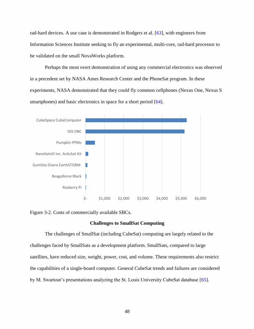
48
rad-hard devices. A use case is demonstrated in Rodgers et al. [63], with engineers from
Information Sciences Institute seeking to fly an experimental, multi-core, rad-hard processor to
be validated on the small NovaWorks platform.
Perhaps the most overt demonstration of using any commercial electronics was observed
in a precedent set by NASA Ames Research Center and the PhoneSat program. In these
experiments, NASA demonstrated that they could fly common cellphones (Nexus One, Nexus S
smartphones) and basic electronics in space for a short period [64].
Figure 3-2. Costs of commercially available SBCs.
Challenges to SmallSat Computing
The challenges of SmallSat (including CubeSat) computing are largely related to the
challenges faced by SmallSats as a development platform. SmallSats, compared to large
satellites, have reduced size, weight, power, cost, and volume. These requirements also restrict
the capabilities of a single-board computer. General CubeSat trends and failures are considered
by M. Swartout’s presentations analyzing the St. Louis University CubeSat database [65].
$- $1,000 $2,000 $3,000 $4,000 $5,000 $6,000
Rasberry Pi
Beagalbone Black
GumStix Overo EarthSTORM
NanoSatisfi Inc. ArduSat Kit
Pumpkin PPMs
ISIS OBC
CubeSpace CubeComputer

49
General SmallSat challenges have also been addressed by NASA in the Small Spacecraft
Reliability Initiative [66].
The primary challenge facing SmallSat computing resides in the use of commercial
processors. Since commercial processors are not hardened for radiation, they are affected by
radiation effects as previously described. In addition, modern SoCs and FPGAs are complex
devices that contain additional IP blocks such as on-chip memory, clock management, and
interface controllers. These different components all require separate radiation tests to determine
each individual component’s error modes and upset rates. This realization further complicates
the design process, as radiation testing is both time-consuming to plan effective tests and conduct
actual testing. Lastly, radiation testing is very expensive, which prohibits many organizations
from testing the devices they fly.
Commercial devices are constantly pushing the bounds of new technology and interact
with radiation in different ways, occasionally exhibiting new effects never before observed on
other devices. In Lee et al. [67], the authors describe an unconventional single-event latch-up,
also called “micro latchup,” that was discovered in new FPGA technology used for flight
missions.
University programs and hobbyists rely on commercial off-the-shelf CubeSat kits, both
for convenience and simplicity of development. Steven Guertin at NASA Jet Propulsion Lab
(JPL) has been conducting studies on common CubeSat microcontrollers and microprocessors
found in CubeSat kits, starting with his initial report in 2014 [68], with follow-up reports each
year at NEPP. His testing reveals that, while relatively resilient to TID for Low Earth Orbit
(LEO), most of these CubeSat kit devices show significant problems caused by latch-up. These
results do not guarantee that a device will fail; however, they highlight that during a low-

50
probability event in LEO, the device may suffer from significant issues. The Air Force Research
Laboratory has also conducted independent testing on common commercial kits in Avery et al.
[69].
The last challenge, highlighted by NASA Goddard’s presentation on Clagett et al. [70], is
that certain tasks such as flight software, communications, ground systems, and attitude control
system, fundamentally require the same functions as larger spacecraft with comparable analysis
and testing. Their mission made compromises to sensor data acquisition to perform all the
desired flight-software processing onboard with the selected microcontroller.
Better Computing with Hybrid Approach
Next-generation spacecraft missions seek to accomplish even more significant science
and defense objectives with SmallSats. New missions are proposed for more-challenging
radiation environments than LEO, including Lunar, Mars, and deep space. To accomplish these
objectives, computing will have to achieve a sufficiently high level of both performance and
radiation reliability.
Dylan et al. [12] and the subsequent chapter proposes a multifaceted, hybrid-design
methodology to achieve the benefits of both commercial and rad-hard designs. This approach
proposes a hybrid-system architecture, where commercial technology is featured for high
performance and energy efficiency, while the device is supported and managed by rad-hard
components for increased reliability. Additionally, the reliability is bolstered by fault-tolerant
computing strategies applied atop the commercial device. This hybrid approach also describes
use of a hybrid device (e.g., CPU+FPGA SoC) as the featured commercial processor to
maximize performance by optimizing algorithms based upon architecture needs.

51
CHAPTER 4 CONCEPTS OF HYBRID, RECONFIGURABLE SPACE COMPUTING
The primary contribution of this dissertation is to introduce the previously mentioned
hybrid-computing concept for space computers. This novel computing-design philosophy,
known as “CSP the concept” is a concept for a multifaceted, hybrid-processing, space system.
This concept centers on having both a hybrid-processor and hybrid-system architecture. A
hybrid-processor device with mixed technology, also known as System-on-Chip (SoC) device,
can achieve immense computational benefits depending on an algorithm’s structure. For
example, with a mixed FPGA+CPU combination, a parallel algorithm can be hardware-
accelerated on the FPGA fabric, while control-flow operations can be performed on the CPU
cores.
The CSP concept also features a hybrid-system architecture, which is a combination of
three themes: commercial-off-the-shelf (COTS) devices; rad-hard devices; and fault-tolerant
computing strategies. Commercial devices have the energy and performance benefits of the latest
technology advancements, but are susceptible to radiation in space, whereas rad-hard devices are
relatively immune to radiation, but are more expensive, larger, hard to procure, and outdated in
both performance and functionality. The keystone principle of the CSP concept is to include a
device with commercial technology featured for the best in high performance and energy
efficiency, but supported by rad-hard devices monitoring and managing the commercial devices,
and further augmented by strategies in fault-tolerant computer architecture (FTCA). This concept
is illustrated in Figure 4-1.

52
Figure 4-1. Illustrated CSP concept diagram.

53
CHAPTER 5 RELIABILITY METHODOLOGY FOR SMALLSAT COMPUTERS
In literature, there is no straightforward method to follow to predict the failure and upset
rates of any given single-board computer in a given Earth-centric orbit. In order to be able to
determine the reliability of a design and compare the given design to other configurations and
other boards, we developed a methodology [71] for estimating the reliability of SmallSat
computers in radiation environments. This new methodology is built upon established reliability
techniques and including PRA concepts to reflect overall reliability (and other measures) of the
space-computer system due to radiation effects as quantifiable values. Figure 5-1 depicts an
overview of the methodology, which consists of four key stages.
Figure 5-1. Reliability methodology stages.

54
Methodology Stages
To provide step-by-step examples of the methodology in use, a configurable space-
computer board was selected and analysis was performed as a case study. This board is a multi-
faceted, hybrid computer called the CSPv1. The following sections describe the methodology,
using several case-study examples to illustrate the process.
Stage 1: Component Analysis
The first stage of the methodology is to compile a list of all EEE components that
constitute the current or proposed board design. This stage is relatively simple, but sets the
foundation for the rest of the analysis, because the engineer should become familiar with
different characteristics of the components. Once the list of EEE components is collected, each
component should be then classified into device family (Processor, Memory, Analog, Digital,
Power, Mixed Signal, etc.), feature size, process type, and function. It is important to have this
information in advance of the analysis, since each of these characteristics helps define a
component’s response to radiation. Several resources and tools are available to help examine
radiation effects by component. One prominent tool is the NASA CubeSat Radiation tool by
NASA Goddard which compiles a list of families of each device and their susceptible SEE
effects. Finally, the reliability engineer should consider the depth of the analysis to be performed
for the mission, and select components for the final analysis. For example, in some missions it
may not be necessary to include analysis for passive components (resistors, capacitors, etc.) or
some simple analog components, and analysis is only performed on active components.
Stage 2: Radiation Data Collection
Once the list of key components is formulated, a broad search must be conducted to
collect all available radiation data for each component, focusing on data relating to effects
specified by the device family. This radiation data can be acquired from many sources including

55
manufacturer datasheets, independent testing publications, IEEE Nuclear and Space Radiation
Effects Conference (NSREC) proceedings, or most commonly the NASA Goddard Radiation
Database1.
The key focus in this stage is to examine each desired component in the design and
determine if it should be used in the final mission or design. In this stage, we can employ RHA
and SEECA to examine the component’s risk. Due to the expansive number of existing EEE
components compared with the number of EEE components that have been flown or have
radiation data, it is unlikely that the exact desired component exists in any publically available
database. Without access to internal databases from large organizations, it is difficult to acquire
actual mission data, so the next best data is from archived radiation testing.
If a part has radiation test data that is valid for the given mission parameters, then there is
no more work to be done in this stage. If a part has no radiation data, or responds poorly to
radiation effects, then the system designers will have to decide if the part should still be used. If
it is decided that the part will be used in the design, but has no radiation test data (accepting
risk), then for the purposes of the system-level analysis, suitable data will need to be input. This
suitable data will typically be previous archival radiation-test data that comes from similar
components to the original device that have already been tested. LaBel et al. [20] offers guidance
and commentary on how representative the data pulled from archives can be to the real data, as
well as several recommendations for this type of procedure. Ladbury [30] gives several
suggestions on how to pick the next best data to use for the analysis and is illustrated in Figure
5-2. In the ideal best-case scenario, there will be representative flight-lot specific data. Since this
scenario is unlikely with newer COTS components, the next closest representative data should be
1 https://radhome.gsfc.nasa.gov/radhome/raddatabase/raddatabase.html

56
selected as illustrated in Figure 5-2. Once a device has been selected, we refer to the device data
that is used in the analysis as the Radiation Tested Replacement Part (RTRP).
Figure 5-2. Statistical structure of representative data [30].
There are two main goals from this stage of the data collection. The first is to obtain a
Weibull curve describing the Cross Section vs. Effective Linear Energy Transform (LET) curves
for every component’s relevant SEEs. Figure 5-3 from Oldham et al. [72] shows example points
that will be used to generate a Weibull curve for a non-volatile memory component used in the
case study. These curves serve as inputs into a mission simulator (like CREME96 or SPENVIS)
to predict error rates for each type of SEE. In some scenarios, the actual data values may not be
provided and the reference may only provide a chart. In these scenarios, MATLAB is used to
generate a best estimation for the Weibull curve. The best Weibull model fit is calculated by
estimating key points on the chart visually and having MATLAB perform an automated least
squares regression. The second goal of this stage is to acquire a TID value for each component,
All relevant data (ARD)Physics
Technology TrendsPart GenerationExpert Opinion
Similar PartsSame Fabrication Facility
Same ProcessSimilar Design Rules
Historical DataSame Part Type, #
Flight Lot
Flight Part
VariabilityM
ean

57
which will typically be recorded in krads. This number will help in the future stages to determine
component survivability in the mission environment.
Figure 5-3. Example cross section vs. LET graph [72].
Stage 3: Mission and Model Parameter Entry
For the third stage of the methodology, the data collected in the first and second stages is
used with specific mission characteristics (such as orbit) that define the mission environment and
is entered into tools used for SEE and TID prediction rates for that environment. Key tools for
this type of analysis include CREME962 and SPENVIS3, which can be used to estimate the
expected SEE and TID respectively for the components within the mission specifications. Table
5-1. SEU upset rates for non-volatile memory reported by CREME96. provides an example of
expected output results from CREME96. This table displays the specific SEU upset rates for a
non-volatile memory used in the CSP case study. Table 5-2 displays a subset of outputs for
2 https://creme.isde.vanderbilt.edu/
3 https://www.spenvis.oma.be/

58
SPENVIS, with the specific values for a year in the same low-Earth orbit (LEO) used in the case
study. Here, SPENVIS is used to calculate TID because CREME96 does not take into account
the additional fault rate from trapped protons, while CREME96 is used to calculate SEEs. A
detailed description of CREME96 functionality (including a walkthrough for configuring it) is
presented in Engel et al. [74].
Table 5-1. SEU upset rates for non-volatile memory reported by CREME96.
Type Rate
SEEs/bit/second 1.08E-24
/bit/day 9.30E-20
/device/second 8.61422E-15
/device/day 7.44268E-10
Table 5-2. Typical TID amounts for LEO with 1-year mission reported by SPENVIS
Al (mils) Total (rads) Trapped Electrons
(rads)
Brems-
Strahlung (rads)
Trapped Protons
(rads)
1.968 6.140E4 5.850E4 1.070E2 2.800E3
98.425 2.906E2 1.963E2 1.778E0 9.255E1
196.850 9.858E1 2.711E1 8.719E-1 7.059E1
787.400 4.146E1 0.000E0 2.771E-1 4.119E1
Certain components may only have results from proton testing, or only have heavy-ion
data and need results for protons (in LEO, upsets are dominated by trapped proton upsets). In this
scenario, we consult the method presented by Barak et al. [75] and Petersen [76]. These papers
explain how to use the Figure of Merit (FOM) approach to estimate the missing SEU rates based
on known data from a particular cross section. More concisely, FOM explains how to predict the
heavy-ion upset rate if the cross section for protons is known and vice versa. Once the missing
rates have been calculated, such information is also entered into the tools.
Stage 4: Fault-Tree Construction, Iteration, and Modification
The final stage is to construct the DFT from a study of the computer architecture as well
as component interactions, board schematic, and layout. The main goal is to devise a DFT that

59
represents the failure sequences of the system (as mentioned previously, the accuracy of this
model is dependent on the competency of the designer). As described in the second stage, there
should be a basic fault event for each of the applicable SEE types to the component. A basic fault
event is pictured in Figure 5-4, and is where the SEE fault rates from CREME are entered. In
Figure 5-4, the heavy-ion upset rate (HUP) and proton upset rate (PUP) are basic events for the
non-volatile memory we have been using as an example. Windchill Predictions displays
unreliability (Q) of the component at a fixed point in time, which is set to 24 hours for this study.
The fault rate must be converted from faults/upsets per day as provided by CREME to
faults/upsets per billion hours (109), known as Failures in Time (FIT). This fault tree is
constructed with the PTC Windchill Predictions (formerly Relex Reliability Prediction) software,
a recommended tool for NASA reliability calculations, for both computation and analysis. This
methodology is not limited to this specific software and can be used with any fault-tree tool as
long as the system design can be accurately reflected. Windchill Predictions is relatively easy-to-
use and includes several DFT gates in the toolset [38]. Some key modules that could have
extended fault trees depending on the board are listed below:
• Microprocessor Failure
• Passive Component Failure (Resistors etc.)
• Programming Circuitry Failure
• Supervisory Circuit Failure
• Timing Reference Failure
• Memory Failure
• Transmitter / Receiver Failure
In this methodology, each of these key design modules should be considered. Figure 5-5
illustrates the top-level hierarchy of the CSP case study with transfer gates to each of the
described modules, which are expanded into their own fault trees. In our case study, we have
elected to focus on the microprocessor (Zynq), memory, and power regulation modules. For

60
reference, parts of the case-study memory module are illustrated in figures here. The memory
module transfer gate (shown in dashed box) in Figure 5-5 is expanded in Figure 5-6. Figure 5-6
shows that a memory failure can result from volatile or non-volatile memory. Within that
memory module, the non-volatile memory transfer gate (shown in dashed box) is expanded in
Figure 5-7. Figure 5-7 is the fault tree for the NAND flash memory used in the case study. The
fault tree illustrates a particle strike causing a SEFI or SEU (as shown in Figure 5-4) and the
NAND flash failing due to usage (wear). Some parts of the fault tree are specific to the case-
study design. Calculations for an upset in the boot partition of the NAND flash are evaluated in a
different fault tree. Additionally, there is an inhibit gate entry to reflect that, in this design, a
failure of the NAND flash will not cause the board to fail unless the processor restarts. If the
processor is currently running, it would just note that the NAND flash was disabled and continue
nominal operation.
Figure 5-4. Basic event for a SEU to memory cell in non-volatile memory from heavy ions or
trapped protons.
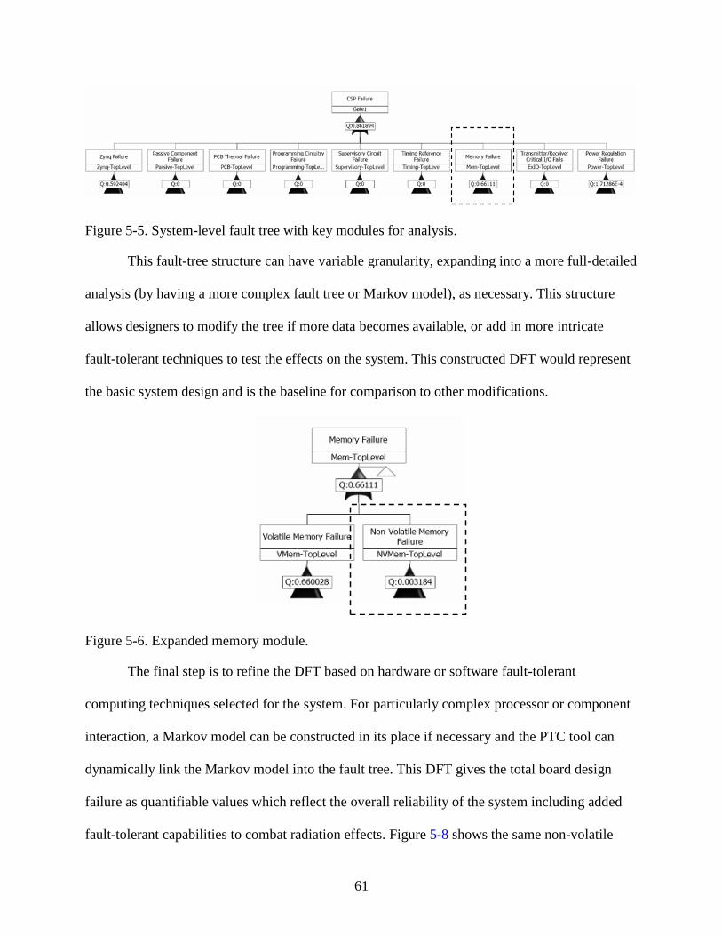
61
Figure 5-5. System-level fault tree with key modules for analysis.
This fault-tree structure can have variable granularity, expanding into a more full-detailed
analysis (by having a more complex fault tree or Markov model), as necessary. This structure
allows designers to modify the tree if more data becomes available, or add in more intricate
fault-tolerant techniques to test the effects on the system. This constructed DFT would represent
the basic system design and is the baseline for comparison to other modifications.
Figure 5-6. Expanded memory module.
The final step is to refine the DFT based on hardware or software fault-tolerant
computing techniques selected for the system. For particularly complex processor or component
interaction, a Markov model can be constructed in its place if necessary and the PTC tool can
dynamically link the Markov model into the fault tree. This DFT gives the total board design
failure as quantifiable values which reflect the overall reliability of the system including added
fault-tolerant capabilities to combat radiation effects. Figure 5-8 shows the same non-volatile

62
memory module structure in Figure 5-7, but enhanced with error-correcting code (ECC) with an
inhibit gate (shown in dashed box).
Windchill Predictions can calculate different reliability measures for the top-level gate
(processor failure) once the system fault tree has been constructed and all fault rates have been
entered as basic events. The calculator takes time and number of data points as inputs and can
calculate unreliability, failure rate, frequency, and number of failures. From these calculated
metrics other reliability measures can be derived, such as mean time to failure and upset rate per
day. Lastly, the tool can export all its results to a Microsoft Excel spreadsheet to be used in any
other analysis as desired. Figure 5-9 shows a graph generated by the Windchill Predictions tool
of board failure from the case study, in terms of unreliability vs. a 24-hour timeframe.
Reliability measures are important for building a baseline to allow comparisons of the
same board with modified parts or fault-tolerance strategies or with other space-computer
hardware and software configurations. These values allow us to specifically compare different
component configurations (all-commercial, hybrid, all-rad-hard design) to determine the amount
of reliability gained from additional fault-tolerant components, as well as the associated
monetary cost for extra reliability. This same strategy can be deployed across the same board
with different software fault-tolerance strategies through appropriate fault tree or Markov model
additions. The fault tree can only account for SEE effects and is plotted in an unreliability vs.
time graph, which will be referenced when accounting for TID.

63
Figure 5-7. Expanded non-volatile memory section.
TID cannot be properly reflected in the fault tree due to configuration limitations in
Windchill Predictions. After obtaining the TID information by entering mission specific
parameters into SPENVIS, the survival duration for each component is calculated. Using the
fault-tree structure to determine which component failures are survivable, the time until failure
due to TID can be calculated. In the simplest scenario, if no components can fail without causing
the entire computer to fail, the survival time due to TID is the time until failure for the
component with the lowest TID. This calculated time to fail due to TID is then assumed to be the
maximum time for the analysis so the unreliability vs. time graph for SEEs ends at this
calculated time.

64
Figure 5-8. Non-volatile memory module with ECC.
A modified approach is required in a more complex scenario where, due to fault
tolerance, a system can survive certain component TID failures. When a component fails and is
removed from the system, this changes the fault-tree structure of the system and by extension its
reliability. To properly account for this change, a new fault tree is created with the component
removed. This change creates a discontinuity in the original graph, so the new graph will look
like a piecewise function, where the original fault tree is used up to the time where the

65
component should fail, then the new fault tree is used from this point onward to reflect the
changes in the system.
While this research is not encompassing of all radiation analysis techniques, it still
provides the reliability engineer with a practical method to model and compare different space-
computer designs and study the tradeoffs. Eventually, we hope to expand this model to reflect
other metrics including performance and availability, and other forms of radiation analysis.
Figure 5-9. Graph generated by Windchill Predictions for case study board failure.
Mitigation Guidelines
The methodology expresses an iterative process where the design is analyzed then
modified, repeatedly. This paper does not cover different mitigation strategies or how to model
them in a fault tree or Markov model, however, some suggestions are provided with additional
methods described by Foucard [77]. For failures due to TID, spot/sector shielding can be used to
provide some protection. If unacceptable fault rates are generated from SEEs, then components
can be up-selected to a higher-grade component or more system redundancy can be included.

66
CSPv1 Analysis
CSPv1 provides a unique example of a design that is configurable, and it also serves as a
useful case study for deploying the new methodology. The most useful feature of this processor
for this analysis is that it has a selective population scheme for several components. This scheme
allows certain components of the board to have both commercial and radiation-hardened
footprints to populate the design. This approach allows the user to scale reliability and cost by
selecting different components. For the case study, an all-commercial variant of the CSPv1 is
compared with a CSPv1 that has all the available rad-hard footprints populated (hybrid CSPv1).
Case Study: Description and Assumptions
For this case study, the methodology steps were completed for the two CSP designs. DFT
models were constructed for the COTS variant and hybrid variant that included the rad-hard
components. The full DFT diagram is too large to be reasonably and coherently displayed in this
paper, but the general structure for a module has already been illustrated with Figure 5-4 to
Figure 5-8. Each component of the CSPv1 was analyzed and the fault rates by SEE type were
entered as basic events in the DFT as described by Figure 5-4. Finally, these fault rates and
relevant data were collected for analysis for both boards in two different orbits: Low-Earth Orbit
(LEO) and Geostationary-Earth Orbit (GEO).
This study assumes 98.425 mils of aluminum shielding. The representative LEO orbit for
this study is the International Space Station orbit, while the representative GEO orbit is the
AMC-18 satellite orbit. The DFT models were constructed without any additional fault tolerance
and represent the basic system. Finally, it should be noted that there was no available radiation
test data for several commercial components. In these cases, the best estimate was based on
available data and the RTRP selections as described in the methodology section.

67
Lastly, it should be noted that there is a discrepancy between vendors’ provided radiation
data and commercial component data. In studying this issue, engineers discovered that a
commercial NAND flash obtained better results than reported by vendors for the radiation-
hardened counterpart. One reason for this discrepancy could be vendors reporting lower numbers
to keep within acceptable manufacturer-guaranteed ranges, which may be below the actual
capability. In these situations, the radiation-hardened variant is expected to perform better than
the reported data suggests. Therefore, for this case study, if the COTS fault rates were lower than
the radiation-hardened fault rates, then the radiation-hardened numbers used for the analysis
were increased to be at least equivalent to the COTS numbers.
Case Study: Results and Analysis
For survivability and lifetime results, mission-specific parameters were placed into
SPENVIS for both LEO and GEO environments, and the overall expected TID was generated for
a year (Table 5-3). For the design, no components are able to fail without causing a complete
board failure, therefore the lowest TID of the available components is compared to the overall
expected TID and a simple ratio calculation gives the amount of time until the component fails.
These results are reflected in Table 5-4.
Table 5-3. Yearly TID by orbit.
Orbit Expected TID
LEO 0.29 krad/year
GEO 71.3 krad/year

68
Table 5-4. Estimated board lifetime.
Configuration Orbit Lifetime
CSP (Either Configuration) LEO ~10+ Years
CSP-COTS GEO ~100 Days
CSP-Hybrid GEO ~200 Days
For SEE and transient upset results, DFTs were constructed for both configurations of the
board and reliability measures were generated by Windchill Predictions. Windchill Predictions
also has the capability to calculate results for all intermediate gates within the system fault tree,
so certain modules can be explored. The most interesting module for this comparison is the
power-system module, since this module varies the most between our two case-study boards
(i.e., the hybrid CSPv1 has rad-hard power regulation components).
Several main observations can be drawn from this study, which demonstrate the
usefulness of the methodology. First, after examining the upset rates of the submodules of the
fault tree, the system upset rate is primarily dominated by common components (Zynq, DDR) in
both the COTS and hybrid variations, so both boards will have similar upset rates reported in any
orbit. Since the results are similar between both boards, Table 5-5 shows the expected upset rate
for each of the studied orbits without differentiating between configurations. This finding is
displayed in Figure 5-10, which contains the reliability curves in both orbits for the boards, as
well as the Zynq and DDR components for comparison.
While the overall system reliabilities are similar, Figure 5-11 shows the reliability of the power
modules in both GEO and LEO orbits. These results show differences between the COTS and
rad-hard components in both LEO and GEO. A comparison of the failure rates of these
components is provided in Table 5-6.

69
Table 5-5. CSPv1 board upset rate.
Computer Orbit Upsets/Day
CSP (Either Configuration) LEO 1.9797
CSP (Either Configuration) GEO 16.235
Figure 5-10. LEO and GEO reliability curves.
Key findings show that SEE upset rates for each board configuration were dominated by
the same COTS components between the board configurations. The rad-hard components,
however, are still useful because they are more resilient to cumulative radiation effects, which
improves the system’s lifetime, even though they have only a minor contribution to improving
SEE upset rate.
We can observe several significant observations while employing the defined
methodology. The results show that since Zynq and DDR components of the board have the
highest upset rates, therefore SEE upset rates between configurations is minimal. This finding
shows weaknesses in the design that can be improved by adding fault-tolerant computing
techniques. In this example, the Zynq can be further mitigated using well known techniques such
0
0.1
0.2
0.3
0.4
0.5
0.6
0.7
0.8
0.9
1
0 5 10 15 20
Rel
iab
ilit
y
Time (Hours)
LEO-Board GEO-BoardLEO-Zynq GEO-ZynqLEO-DDR GEO-DDR

70
as configuration scrubbing and triple-modular redundancy structures. The DDR could be further
mitigated with ECC. This analysis shows the designer which components to focus on to improve
reliability. This analysis also shows that in LEO the rad-hard parts may not be necessary and a
commercial board can be deployed, thereby reducing costs. Lastly, the process in the
methodology highlights information about the environment with which a newer designer may be
unaware, such as the much harsher lifetime and upset rates found in GEO, when compared to the
relatively benign LEO.
Table 5-6. Power system upset/day.
Orbit CSP-COT CSP-Hybrid
LEO 1.713E-03 9.0147E-06
GEO 0.0014 2.6104E-06
Figure 5-11. Power module reliability.
Methodology Insights and Improvements
This section presents a practical methodology to determine and evaluate radiation-
oriented reliability characteristics for space computers from a system-level SmallSat perspective.
This methodology can help designers in gauging the general level of reliability of their design,
0.9984
0.9986
0.9988
0.999
0.9992
0.9994
0.9996
0.9998
1
0 5 10 15 20
Rel
iab
ilit
y
Time (Hours)
ISS-COTS ISS-Hybrid
GEO-COTS GEO-Hybrid

71
comparing its reliability against other designs, deciding on component selection during the
development phase, and evaluating effectiveness of hardware and software fault-tolerance
mechanisms in the design. Our methodology is relevant, even though it has not been validated by
a multitude of radiation tests and comparisons, because it builds on established and widely
accepted methods and techniques, and it combines them to provide an initial analysis of a design.
Additionally, the soundness of this approach has been reviewed with radiation experts at NASA
Goddard and has been approved, noting that assumptions should be clearly stated and limitations
expressed to prevent any unintentional misuse. In this paper, we explored different
configurations of the CSPv1 space computer and evaluated configurations under different
environmental conditions. This methodology has illustrated potential issues in the board design
that can be addressed with fault tolerance. Finally, this study has provided an initial first-order
estimation of both the survivability and expected upset rates of these board configurations.
The methodology established in this paper can be further expanded to cover more
advanced types of analysis and provide even more accurate predictions. CSPv1 has already been
exposed to neutron-beam testing in both commercial and hybrid configurations. Preliminary
impressions of the neutron test results are expected to confirm predictions examined in this
paper. Further analysis will be performed when the results of those tests are finalized. Additional
topics for future study are listed below:
• Include explicit instructions and descriptions for analysis within a spacecraft using ray
tracing in conjunction with University of Wisconsin-Madison’s Direct Accelerated
Geometry Monte Carlo Toolkit (DAGMC). This method would allow exploration of
modeling of components related to physical location within the board and within the
spacecraft.
• Provide further examples with different fault-tolerant computing techniques employed
within the DFT model.
• Expand the methodology and provide example models to add performance and
availability metrics.

72
CHAPTER 6 CSPv1 DESIGN
The reliability methodology was specifically created to help analyze and design the
CSPv1 board. CSPv1 is the first flight board to evolve from the CSP concept and features a
hybrid-processor and hybrid-system architecture. The processor architecture features fixed (dual
ARM Cortex-A9/NEON cores) and reconfigurable (28 nm Artix-7 FPGA fabric) logic on the
Xilinx Zynq-7020 SoC device. The system architecture combines commercial and rad-hard
electronics with an assortment of techniques in fault-tolerant computing to achieve a system with
a powerful combination of high speed and reliability with low power, size, weight, and cost
(SWaP-C).
Hardware Architecture
Some specifications of the Xilinx Zynq-7020 device used by CSPv1 are provided in
Table 6-1 and Table 6-2, a block-level diagram is provided in Figure 6-1. Attached to the ARM
side of this device, the CSPv1 can support up to 1 GB of DDR3 memory (maximum capacity
supported by the DDR3 controller).
The CSPv1 is designed to fit a 1U standard CubeSat form factor (10 cm × 10 cm). All
external connections to the CSPv1 board are made through a 160-pin Samtec Searay connector.
There are 60 connections from the FPGA side of the Zynq, where 48 pins can be configured as
24 differential pairs for high-speed interfaces. There are also 26 high-speed connections from the
ARM side of the Zynq that can be configured in a combination of varying communication
interfaces including UART, I2C, and SPI.

73
Table 6-1. Xilinx Zynq-7020 ARM specifications1.
ARM Specifications
L1 Cache Per Core 32 KB Instruction / 32 KB Data
L2 Cache Shared 512 KB
On-Chip Memory 256 KB
Clock Frequency 667 MHz (-1 Speed Grade)
Table 6-2. Xilinx Zynq-7020 FPGA specifications
FPGA Specifications
Programmable Logic Cells 85,000
Look-Up Tables 53,200
Flip-Flops 106,400
Block RAM / # 36 Kb Blocks 4.9 Mb / 140
DSP Slices 220 (18 x 25 MACCs)
Figure 6-1. CSPv1 Rev B. block diagram.
1 https://www.xilinx.com/support/documentation/data_sheets/ds190-Zynq-7000-Overview.pdf

74
The CSPv1 Rev. B has a unique selective population scheme for several components that
enables certain components of the board to include both commercial and rad-hard PCB footprints
to populate in the design. This approach enables the user to scale reliability and cost by selecting
different components for mission needs. Figure 6-2a shows a populated board using all
commercial components (CSPv1 Rev. B Engineering Model or CSPv1 Rev. B EM), where the
unpopulated regions are for the placement of equivalent rad-hard components. Figure 6-2b shows
the populated board inserting rad-hard components in compatible areas, this board is the CSPv1
Rev. B flight board. Additionally, it has the ancillary benefit of allowing mission designers the
option to purchase or configure a low-cost, easy-to-develop, all-commercial testbed that is highly
reflective of flight hardware. Configurable subsystems within CSPv1 Rev. B that include
selective options are the non-volatile NAND Flash memory (commercial Spansion 8Gb or
radiation-tolerant 3D-Plus 32Gb), switching regulators (commercial Texas Instrument or rad-
hard e2v Peregrine), linear regulators (commercial Texas Instruments or rad-hard Cobham),
supervisory circuit (Intersil commercial and rad-hard variants), power sequencing (Texas
Instruments commercial and rad-hard variants), and finally reset management (Texas
Instruments commercial and rad-hard variants).
A B C
Figure 6-2. CSPv1 designs. A) CSP Rev. B EM. B) CSP Rev. B Flight. C) CSP Rev. C.

75
CSPv1 requires two input voltage rails (3.3V and 5.0V) to the board, and generates the
remaining necessary voltages with internal regulation. The entire CSPv1 Rev. B board has been
analyzed for total power consumption in a variety of different configurations to reflect use cases
that may be expected in several mission scenarios, as listed in Table 6-3. To measure power
consumption, the CSPv1 was interfaced with a test board that was used solely to provide power
inputs. The measurements shown in Table 6-3 were taken from an external power supply
connected to the CSPv1 through this test board.
Table 6-3. CSPv1 Rev. B power consumption.
Operating Frequency (MHz) Test Load
ARM DDR FPGA ARM FPGA Power (W)
200 200 100 Low Low 1.54
200 200 100 High Low 1.78
667 533 100 High Low 2.23
667 533 100 High High 2.86
For ground testing, the CSPv1 connects to an evaluation board with convenient interfaces
for rapid desktop prototyping of flight designs. The evaluation board exposes internal signals on
the CSPv1 connector from both the ARM and FPGA side of the device. For FPGA signals, the
evaluation board provides connectors for Camera Link, SpaceWire, and several spare single-
ended and differential signals. For ARM signals, the evaluation board provides Ethernet and
USB-Host capabilities. A secondary purpose of the evaluation board is to serve as a reference
design for the integration of various interfaces and devices. Two revisions of the evaluation
board exist and are pictured in Figure 6-3. The Rev. B added quality-of-life changes including a
3rd SpaceWire connector, a 1V8 regulator for the Ethernet PHY (in place of using the CSPv1

76
regulation), debug LEDs, and additional mounting holes. The datasheet for the CSPv1 can be
downloaded from the Space Micro product page2.
A B
Figure 6-3. CSPv1 Rev. B mated to Evaluation Boards. A) Rev. A Evaluation Board. B) Rev. B
Evaluation Board.
Software Design
CSPv1 is equipped with an extensive and thoroughly tested software package. This
package includes support for two operating systems (Linux and Real-Time Executive for
Multiprocessor Systems or RTEMS), a variety of applications and drivers developed by the
research center, and platform-support packages for both operating systems in Core Flight
Executive (cFE3), NASA Goddard’s open-source, reusable, flight-software framework for local-
device management, event generation, software messaging, and support libraries.
Our research center has developed its own lightweight Linux environment, named
Wumbo, built using Buildroot. Xilinx's linux-xlnx fork of Linux is used as the kernel, and
2 http://www.spacemicro.com/assets/datasheets/digital/slices/CSP.pdf
3 http://coreflightsystem.org/

77
BusyBox is used for most of its user-space tools. For missions with real-time constraints, the
CSPv1 supports the open-source RTEMS with comparable CSPv1 support to Linux. Finally, it
should be noted that VxWorks does run on CSPv1, however, a full CSPv1 development system
is not supported due to the overhead of creating custom drivers to provide the expected
functional feature set. To perform onboard processing, the research center has developed serial
as well as OpenMP-, NEON-, and OpenMPI-accelerated versions of commonly used image-
processing applications including image compression and basic filtering.
Fault-Tolerant Computing Options
The CSPv1 architecture was designed to support the selective population scheme to
enable commercial components to be replaced with rad-hard variants in board assembly.
Additionally, the Zynq has three internal watchdogs which can be used to detect and correct
system faults. An external supervisor circuit with hardware watchdog was integrated into the
CSPv1 to monitor the processing device for radiation upsets, and reset if the processor is not able
to mitigate a fault internally.
The ARM side of the Zynq is connected to the non-volatile memory and is responsible
for configuring the system, including the FPGA, on boot. As a precaution, for the critical booting
process, CSPv1 repurposes the built-in RSA authentication features of the Zynq to check boot
images before startup. As an additional safety measure, multiple boot images can be stored in a
read-only partition of the non-volatile memory to be used as a fallback should any images
become corrupted by radiation during the mission duration. On boot, the Zynq BootROM will
continue to search for images to load until it finds a valid (uncorrupted) one.
Once the boot image is verified and the device is booted, the CSPv1 runs Wumbo.
Optional improvements and modifications to the system can be made to increase fault tolerance
including: disabling the caches, enabling error-correcting codes (ECC) on the DDR3 memory,

78
and reporting parity faults on the caches if enabled. Fault detection within the kernel is also
improved with the addition of rebooting on kernel panics, soft- and hard-lockup detection, and
the Error Detection and Correction (EDAC) module. Together, these improvements achieve
higher reliability, longer average system up-time, and more detailed system reports on upset
events.
One of the main challenges for incorporating an FPGA device in a spacecraft system
stems from the SRAM-based memory architecture, which is susceptible to SEEs. SEEs can
manifest as bit flips in FPGA configuration or data memory, which can eventually lead to device
failure. One solution to these issues is configuration scrubbing; the process of quickly repairing
these configuration-bit upsets in the FPGA before they accumulate and lead to a failure. CSPv1
features a readback scrubber which periodically reads back the entire configuration memory and
performs writes to configuration frames that correct configuration memory without disturbing
other dynamic portions of memory. Additionally, CSPv1 has access to a more efficient hybrid
scrubber, which reduces overhead significantly and improves error-correction latency over the
readback scrubber, and takes advantage of both built-in, single-bit correction and ECC.
A fault-tolerant framework was developed for hybrid CPU and FPGA architectures in
[73] that can be applied to CSPv1, this framework is further described in Chapter 10. This
framework takes advantage of the Zynq’s architecture to provide several different fault-tolerant
modes (e.g. duplex with compare, triple-modular redundancy) by leveraging both the ARM cores
and FPGA fabric.

79
Design Revisions
As with any development system, the CSPv1 has undergone several revisions to make
improvements. The changes from Rev. A to Rev. B were minor, including: (1) tweaking passive
component values; (2) revising footprints for better connections; (3) adding additional mounting
holes for mechanical stability; (4) changing FPGA connections to the NAND memory chip
enable for bank switching; and finally (5) replacing a Zener diode with a voltage divider due to
radiation survivability concerns. The CSPv1 Rev. B was designed for Low-Earth orbit (LEO)
and similar orbital conditions. The CSPv1s currently in orbit have not experienced any critical
failures. However, interested sponsors advocated the use of CSPv1 for more challenging
environments, therefore, major design changes were applied from Rev. B to Rev. C in support of
deep space and Lunar missions that require higher reliability. During the heavy-ion radiation test
of the Flight Rev. B design, testers discovered that under certain conditions, heavy radiation
exposure caused part of the power system to malfunction, specifically, the board would lose the
“power good” status and crash. After further component analysis, the CSP team predicted that
the most likely culprit of these failures was the commercial Texas Instruments (TI) DDR
regulator (TPS51116PWP). Since the original design, TI developed new rad-hard components
that could be used to replace the commercial regulator. The CSPv1 Rev. C replaces the
commercial regulator with a pair of radiation-hardened regulators (TPS7H3301-SP, TPS50601-
SP) to provide the same functionality. It was later confirmed by a radiation test of the Rev. C that
this issue had been resolved. Unfortunately, due to the extensive nature of these changes, the
CSPv1 Rev. C, pictured in Figure 6-2c, does not support the selective population scheme
featured in the Rev. B.

80
CHAPTER 7 PERFORMANCE ANALYSIS OF CSPv1
This section studies the performance of the Xilinx Zynq featured on CSPv1, to provide an
example of the general capability to be expected, and to emphasize the benefit of commercial
processors over state-of-the-art rad-hard processors. Table 7-1 provides the maximum theoretical
throughput (gathered from vendor datasheets) for the devices with the concept of device metrics
described by Lovelly et al. [61]. As Lovelly describes, Computational Density (CD), measured in
GigaOps/second (GOPS), is a metric to describe the steady-state performance of a processor’s
computation for a stream of independent operations. These numbers represent the stand-alone
processor architecture, and do not reflect interactions with on-chip memories (caches etc…),
external memories (DDR memory), or off-chip resources. Lovelly, provides separate metrics to
measure these interactions called Internal Memory Bandwidth (IMB), External Memory
Bandwidth (EMB), and Input/Output Bandwidth (IOB) respectively. These calculations are
based upon a 50-50 mix of addition and multiplication operations, that is representative of
common and critical operations in many computational kernels of space applications. Table 7-1’s
columns for CD illustrate the disparity in performance between established rad-hard devices
(HXRHPPC, RAD750, GR712RC, GR740) and the commercial device (Zynq). Additionally,
these results can also be scaled with respect to the devices’ power consumption, as shown in
Table 7-1’s columns for CD per Watt (CD/W), further highlighting the dramatic efficiency gains
of the Zynq over rad-hard devices.
To provide an alternate view of processor performance, we benchmark the available
Zynq processors options with CoreMark, a benchmark developed by the Embedded
Microprocessor Benchmark Consortium. CoreMark contains list processing, matrix
manipulations, state machine, and CRC (cyclic redundancy check) calculations which are

81
frequently used in flight avionics operations. Table 7-2 displays the results of the benchmarks for
a single ARM core with varying cache configurations. These results were run on the Digilent
Zedboard, a commercial evaluation board with near identical Zynq part to CSPv1. The L2 cache
does not appear to improve the performance of the CoreMark benchmark significantly, however,
this result is explained by the benchmark's low memory usage versus the 32KB L1 instruction
and data caches. The benchmarks used in Table 7-2 were compiled with
“PERFORMANCE_RUN" configuration and -O2 compiler optimizations. The number of
iterations tested varied, 1,000 for MicroBlaze and 100,000 for ARM. This discrepancy results
from the time required for the MicroBlaze to execute 100,000 iterations. The precision error is
minimal over 10 seconds of execution. The Microblaze was configured with PERFORMANCE
optimization (5-stage pipeline), integer multiplication/division and FPU were enabled, and
caches disabled.
Table 7-1. Computational density and computational density per Watt of popular rad-hard
processors and the Zynq
Processor CD (GOPS) CD/W (GOPS/W)
Int8 Int16 Int32 SPFP DPFP Int8 Int16 Int32 SPFP DPFP
Honeywell
HXRHPPC 0.08 0.08 0.08 0.08 0.04 0.01 0.01 0.01 0.01 0.01
BAE Systems
RAD750 0.27 0.27 0.27 0.13 0.13 0.05 0.05 0.05 0.03 0.03
Cobham GR712RC 0.08 0.08 0.08 0.03 0.03 0.05 0.05 0.05 0.02 0.02
Cobham GR740 1.00 1.00 1.00 1.00 1.00 0.67 0.67 0.67 0.67 0.67
Xilinx Zynq-7020 283.3 152 46.29 40.57 12.63 60.41 36.91 10.72 7.83 3.06
This analysis with caches is relevant for reliability considerations. The caches occupy a
significant portion of area on any processing device, and therefore, have a higher probability of
experiencing a radiation-induced upset. During neutron testing of the Zynq for CSPv1 as
described in [78], it was noted that the Zynq experienced much worse reliability with caches
enabled. While these L1 and L2 caches on the Zynq are reported to have parity-bit checking
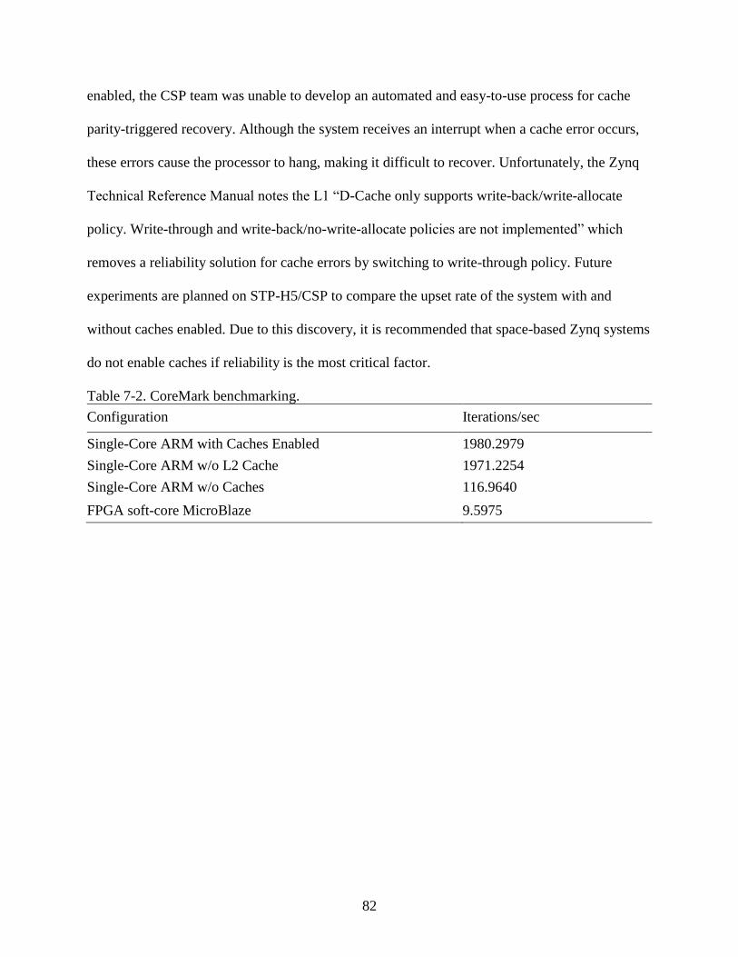
82
enabled, the CSP team was unable to develop an automated and easy-to-use process for cache
parity-triggered recovery. Although the system receives an interrupt when a cache error occurs,
these errors cause the processor to hang, making it difficult to recover. Unfortunately, the Zynq
Technical Reference Manual notes the L1 “D-Cache only supports write-back/write-allocate
policy. Write-through and write-back/no-write-allocate policies are not implemented” which
removes a reliability solution for cache errors by switching to write-through policy. Future
experiments are planned on STP-H5/CSP to compare the upset rate of the system with and
without caches enabled. Due to this discovery, it is recommended that space-based Zynq systems
do not enable caches if reliability is the most critical factor.
Table 7-2. CoreMark benchmarking.
Configuration Iterations/sec
Single-Core ARM with Caches Enabled 1980.2979
Single-Core ARM w/o L2 Cache 1971.2254
Single-Core ARM w/o Caches 116.9640
FPGA soft-core MicroBlaze 9.5975

83
CHAPTER 8 RELIABILITY ANALYSIS OF CSPv1
One of the most crucial requirements for space-system designs is the board reliability;
specifically, its capability to withstand a wide temperature range, the mechanical hardships of
launch, the vacuum of space, and the harsh radiation environment. To prepare for the first CSPv1
missions, the flight and commercial boards were extensively tested in several experiments, and a
reliability methodology was developed to help predict radiation effects in the specific
environments targeted.
Radiation Testing Results
The CSPv1 has been radiation tested in several radiation-beam experiments. This section
describes the outcomes and lessons learned at each test.
Neutron Testing
High-energy neutron testing provides an estimation of system reliability in radiation-rich
environments. The CSPv1 flight board was tested under a narrow beam for several days at the
Los Alamos Neutron Science Center (LANSCE) in December 2014 (shown in Figure 8-1a). The
recorded logs revealed the rad-hard watchdog timer rebooted the board and the EDAC Linux
kernel module reported ECC errors in the DRAM and parity errors in the L2 cache as expected.
Hundreds of errors reported by the Linux kernel were logged over the serial terminal for
analysis. Study of those logs indicated that about 75% of the reboots originated in L2-cache
events, and it is suspected that a majority of the remaining events were caused by the L1 cache,
which were not reported at that time. Additionally, this experiment helped stress test the
hardware watchdog-timer circuitry.
Another neutron-beam test was performed in May 2015 at the TRIUMF facility in
Vancouver, Figure 8-1b, on both the commercial CSPv1 board and several Zynq-based
84
development boards in testing the cross-section of the caches and on-chip memory. Analysis of
the logs showed that the FPGA configuration-memory readback scrubber reported many single-
and multi-bit upsets on the commercial CSPv1 board. The cache and on-chip memory cross-
section tests showed that the no-caches configuration provides a viable option for improved
reliability at the cost of performance.
Brookhaven National Laboratory October 2015 Radiation Test
A heavy-ion test was performed on the CSPv1 Rev. B at the Brookhaven National
Laboratory (BNL) NASA Space Radiation Laboratory (NSRL) facility on October 23, 2015
through October 25, 2015. The test used the "Variable Depth Bragg Peak" (VDBP) method of
SEU testing [79] to enable the team to perform a heavy-ion "system-level" test that irradiates all
parts of the CSPv1 board without delidding or thinning, which is frequently required at other test
facilities. There were two primary goals for this experiment. The first goal was to determine the
survivability of the CSPv1 board by sweeping the board through a wide range of Linear Energy
Transfer (LET) values. This test was completed to determine if any permanent catastrophic
failures could occur on the system. The second goal was to better understand the single-event
upset (SEU) response of the system at a wide range of LET values. This experimental setup is
displayed in Figure 8-1c.
This test was successful and allowed the CSP team to study the CSPv1 Rev. B flight
board’s failure modes due to radiation effects. The first observation was that the Linux system
suffered from many SEU-related kernel reboots, which were logged throughout the experiment.
This experiment confirmed the presence of the Xilinx 7-series “high-current” event (micro-
latchup) at higher LET values, however, the event is not destructive and can be resolved with a
power cycle. Finally, the most critical observation is that under certain scenarios, a new failure
mode was detected where the “power good” status of the regulators would fail. This new failure
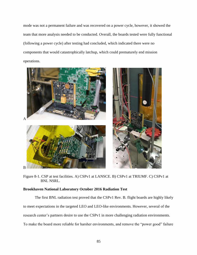
85
mode was not a permanent failure and was recovered on a power cycle, however, it showed the
team that more analysis needed to be conducted. Overall, the boards tested were fully functional
(following a power cycle) after testing had concluded, which indicated there were no
components that would catastrophically latchup, which could prematurely end mission
operations.
A
B
Figure 8-1. CSP at test facilities. A) CSPv1 at LANSCE. B) CSPv1 at TRIUMF. C) CSPv1 at
BNL NSRL.
Brookhaven National Laboratory October 2016 Radiation Test
The first BNL radiation test proved that the CSPv1 Rev. B. flight boards are highly likely
to meet expectations in the targeted LEO and LEO-like environments. However, several of the
research center’s partners desire to use the CSPv1 in more challenging radiation environments.
To make the board more reliable for harsher environments, and remove the “power good” failure

86
mode detected in the previous test, the CSP team developed the CSPv1 Rev. C. Fortuitously,
sponsored by NASA Johnson Space Center’s EV511 group, the CSP team returned to BNL for a
second heavy-ion test.
The CSPv1 Rev. C successfully passed a survivability test without suffering any
permanent damage. The device returned to a fully functional state after manual power cycling
proceeding each run. Additional experiments were conducted to: characterize micro-latchups that
have been previously observed on the Zynq; study the behavior of the ancillary reset circuitry;
and finally, profile the reliability of the NAND Flash memory. The team confirmed the new
design did not suffer from the “power good” error state experienced in the previous test.
However, a new error-mode condition was detected which occurred solely under high flux. At
high flux rates, a current drop-out mode occurs on the 5V0 supply rail causing the Zynq to hang,
preventing the system from rebooting. Fortunately, none of the errors observed during testing
pose a threat to flight, as the conditions needed to trigger them required much higher flux rates
than would be encountered in projected mission orbits.
Radiation Environment Upset Prediction
To estimate the reliability of CSPv1 in different environments, we developed a new
methodology for estimating reliability of space computers from the system-level perspective.
The method, fully described in Chapter 5, can then be used to build a first-order estimate of the
reliability of the system given specific mission-environment conditions. These measures can be
used to assist in making component or device selections by comparing the reliability of the same
design with certain components replaced, comparing the reliability of different space computer
options, and comparing hardware and software fault tolerance within the board design.
One frequent challenge for estimating the reliability of commercial components is that many
commercial parts selected have not been through any degree of qualification or radiation-

87
reliability selection scheme, and even more rarely has the behavior been confirmed and tested in
a radiation-beam environment. The developed methodology consists of four key stages that can
be used to predict upset rate and failure of a design in various orbits, as well as, help make
effective component selections in the board design phase. This methodology was applied to
CSPv1, such that all components (especially commercial components) were analyzed to build a
system model to generate upset rates the CSPv1 may experience in different orbits, relying on
state-of-the-art tools such as CRÈME961, SPENVIS2, and PTC Windchill Quality Solutions3.
Workmanship Reliability
The CSP flight box on STP-H5 underwent environmental and workmanship testing with
STP/H5-ISEM and again with the full STP-H5 pallet. ISEM was required to undergo a
workmanship-level, random-vibration test and a thermal cycle test. The random-vibration test is
performed to identify latent defects and manufacturing flaws in electrical, electronic, and
electromechanical hardware at the component level. The thermal cycle test is performed to
confirm expected performance of a device in a temperature range enveloping mission conditions.
The random-vibration test was performed unpowered, with a sine sweep prior to and after
each principle axis (X, Y, Z). The results of a sine sweep are compared before and after the
random-vibration test to verify there were no changes in frequencies. Any major changes would
indicate an alteration in the structure and would need to be investigated. The workmanship
vibration test of the ISEM assembly was performed successfully on all three axes, with no
significant changes detected during the sine sweeps.
1 https://creme.isde.vanderbilt.edu/
2 https://www.spenvis.oma.be
3 http://www.ptc.com/product-lifecycle-management/windchill/quality

88
The ISEM assembly also underwent a full thermal-vacuum (TVAC) test. A temperature
profile range is selected based on the limits of the components involved and the expected
temperatures on orbit, to expose the assembly to the maximum operational flexibility expected.
The general profile consisted of two cycles in vacuum with a hot operational plateau of 50°C and
a cold operational plateau of -10°C, at the ISEM baseplate interface. A full-functional
performance test was performed at each plateau, with nominal on-orbit activities occurring
during the temperature transitions. The test was performed using minimum and maximum input
voltage at various stages to capture corner cases, as the specified input voltage could be subtly
different based on power converter performance and signal integrity. The STP-H5/CSP
performed nominally throughout the TVAC test, which indicates readiness for mission exposure.
Further details for these experiments can be reviewed in Wilson et al. [78].

89
CHAPTER 9 HIGHLIGHTS OF STP-H5/CSP MISSION EXPERIMENT
This chapter describes the mission-specific configuration of the CSPv1 on STP-H5
(Figure 9-1). STP-H5 was launched February 19th, 2017 and docked with the ISS February 23rd,
2017 and placed on the ExPRESS Logistics Carrier-1 (ELC-1). Now installed, STP-H5/CSP
will be a continuous-development platform for software testing, because new applications,
design cores, and upgrades can be uploaded and tested on board.
Figure 9-1. STP-H51 Pallet 3D-view and integrated-for-flight system
Figure 9-2. STP-H5/CSP flight unit.
1 Photo courtesy of the DoD Space Test Program

90
Mission Configuration
This section describes the main components that constitute STP-H5. This description
includes an overview of the hardware, software, and ground-station operation.
Hardware
The STP-H5/CSP flight box (Figure 9-2) can fit four boards in a 1U form-factor: two
hybrid-flight CSPv1 boards (CSP0 and CSP1); one power/interface board; and one custom
backplane interconnect board. The two CSPv1 boards are set up in a master-slave configuration
where CSP0 receives all ground commands and forwards requests to CSP1 as necessary. CSP0
contains a SpaceWire FPGA core to provide a communication interface to the SpaceCube Mini
and ISS. The backplane board is the central-interconnect interface connecting all the boards
together, directly routing traces between the main connectors. Two SpaceWire and UART
interfaces can be used to pass data between CSP0 and CSP1. The two-board configuration
enables configuration changes to be first tested on CSP1 before any reconfiguration to CSP0,
which is the main interface to the rest of the experiment. The power/interface board consists of
mostly radiation-hardened components and it routes and regulates power to the entire flight unit,
as well as, provides the main communication interfaces. Four external connectors are provided
on the CSP flight box: Camera Link; SpaceWire; power in; and debug I/O. External to the CSP
flight box, a Sony 5-megapixel color camera is interfaced using a Camera Link FPGA processing
pipeline, powered by the FPS experiment.
Software
The CSPv1 flight boards on STP-H5/CSP are configured to boot from the onboard
NAND flash. The Zynq's RSA fallback feature is used to achieve reliable booting with several
“golden” fallback images stored in a read-only partition in flash memory. The next partition
contains space to store additional boot images that are uploaded post-launch. In each boot image,

91
there is a First-Stage Boot Loader (FSBL), Second-Stage Boot Loader (U-Boot), FPGA
bitstream, and Wumbo Linux image. The Linux image uses an initramfs (initial RAM file
system) as its root filesystem and mounts a non-volatile JFFS2 partition after boot.
Contained in the Wumbo image are several key cFS applications. Significant cFS flight-
system applications include the Scheduler (SCH), Health Services (HS), File Manager (FM), and
Stored Commands (SC). SCH is used mostly to schedule telemetry requests to applications. HS
is used primarily to handle watchdog interaction. FM is used to manipulate local files. Finally,
SC is used to execute command sequences, such as an image capture at an absolute or relative
time.
Custom cFE applications that were developed for the STP-H5/CSP mission include:
Command Ingest (CI); Telemetry Output (TO); File Transfer (FT); File Transfer Delivery
Protocol (FTDP); FTDP Receive (FTDPRECV); FTDP Send (FTDPSEND); Image Processing
(IP); Camera Control (CCTL); Self-Timer (SELF_TIMER); CSP Health (CSPH); and Scrubber
(SCR). A custom communication library supplies a frontend for CI and TO to the
communication interface. Depending on compilation options, the backend can be either
SpaceWire or POSIX sockets, and is designed to be transparent to applications. CCTL is used to
interact with the camera, and communicates with SELF_TIMER to capture images at specified
intervals. FTDP and FT are used for file upload and download, respectively. File uploads are
performed over the Communications Interface Board (CIB) which acts as the interface between
the ISS and all the experiments on STP-H5, and downloads are streamed in High-Rate Telemetry
(HRT). IP creates thumbnails of captured images, which are streamed to the ground in
JPEG2000 format. CSPH streams health data such as device temperature, uptime, and memory
92
and CPU utilization, from each of the two flight boards. Lastly, SCR reports messages from the
readback scrubber, which has configurable parameters for scrub rate and detailed error messages.
Ground Station
To monitor the progress of the mission and perform all primary and secondary objectives,
a ground station is setup with commanding software. The ground station deploys the Telescience
Resource Kit (TReK2) to receive and monitor packets sent from STP-H5/CSP. Packets are
received and sent through a graphical user interface (GUI) built to interact with the TReK
software. This GUI was developed with the open source Interoperable Remote Component
(IRC3) application framework with an example configuration for this mission provided by NASA
Goddard. The application framework uses XML descriptions that can be modified to easily
parse, interpret, and display incoming data, as well as, send commands. IRC can be used to save
and store commands through the GUI interface. The GUI also enables the operator to select and
send commands. A Python extension was developed to interface with TReK using Python
scripts. One key Python script is the image viewer, which downloads and displays the thumbnail
images streamed from the STP-H5/CSP flight box.
Primary Mission Objectives
STP-H5/CSP has several primary requirements to fulfill in order to declare mission
success. The first objective of STP-H5/CSP is to advance the Technology Readiness Level
(TRL) of the Xilinx Zynq SoC in Low-Earth Orbit. This device is crucial for study in the
development of a new generation of space computers. It is also one of many devices that are
2 https://www.nasa.gov/sites/default/files/atoms/files/g-28367c_trek.pdf
3 https://opensource.gsfc.nasa.gov/projects/IRC/index.php

93
being considered for the next generation of the SpaceCube family of reconfigurable computers
developed by NASA Goddard’s Science Data Processing Branch.
Another key directive for the mission is to closely monitor and record the upset rates of
both the processing system and programmable logic of the Zynq to provide environmental
information in preparation for future missions. The main upset rates to be examined are the
performance of the ARM cores, as well as, the L1 and L2 caches.
The final primary requirement is to perform image processing, including noise reduction
and image enhancement, on terrestrial-scene data products. Image processing will be
demonstrated with hardware acceleration in the FPGA fabric and compared with processing on
the ARM cores with NEON acceleration. These high-resolution images can then be compressed
using JPEG2000 or converted to PPM for downlink as thumbnails or complete images and
displayed on the ground-station image viewer.
Secondary Mission Objectives
As a technology mission and experiment, STP-H5/CSP has the freedom to explore
additional research-oriented tasks as well as the ability to upload new applications and software,
when not performing primary mission tasks. There are several secondary objectives that will be
explored throughout the duration of the mission including autonomous operations, partial
reconfiguration, space middleware, device virtualization, and dynamic synthesis.
Autonomous Operations
The IP app provides access to our image-processing suite, which includes several
algorithms to perform a variety of functions. For future space-processing missions, it may
become necessary for processing tasks to be completed autonomously. Basic exploratory
functions have been added to CSPv1 to begin testing this domain of applications. The IP app has
a set of algorithms for classifying images. These algorithms can allow CSP0 to autonomously

94
make decisions about which images to keep, without user intervention. In a restricted downlink
scenario, this app can determine if an image taken is unnecessary (e.g., an all-white image from
cloud cover, or all-blue from just the sea), and can delete the image, saving storage capacity as
well as preventing this picture from wasting downlink bandwidth.
In-Situ Upload Capability
The CSP flight box has additional software features, which include software and
firmware uploads. Flight software updates will primarily be made by uploading new cFE table
and configuration files. cFE tables can be used to change the behavior of applications, or even to
load new applications. As an example, an SC table can be uploaded that includes commands for
cFE to start an uploaded cFE application, or stop an old version and load a new one from flash
memory. For more drastic changes, such as a Linux kernel update, new boot images can be
uploaded and stored in the partition in the region after the golden images as described previously.
The new environment will contain instructions for U-Boot on booting the new image. If the U-
Boot environment ever becomes corrupt, U-Boot will default to booting the golden image.
Lastly, additional functionality on this mission includes file transfer between CSP0 and CSP1.
The FTDPRECV and FTDPSEND apps can allow the transfer of large files or configurations
between the two flight boards.
Partial Reconfiguration
The CSPv1 will be one of the first deployed space computers to include Partial
Reconfiguration (PR) functionality. PR, as described in Chapter 2, is the process of changing a
specialized section of reconfigurable hardware during operational runtime. The CSPv1 allows
multiple applications to be performed in the FPGA fabric without reconfiguring the entire
device. PR can be used in space missions to reduce the total-area utilization of the fabric by
switching out designs to reduce the vulnerable configuration area, employing fault-tolerant
95
reconfigurable structures, and allowing new algorithms and applications to be uploaded after
completion of the primary mission. PR can improve the performance of a device by allowing the
user to include a suite of application designs to fit within a PR region, enabling a larger number
of applications to be accelerated by hardware, rather than limited by a single static FPGA design.
The CSPv1’s corrective scrubbing and error logging are also available to PR design regions.
Space Middleware
The CSP explores new fault-tolerant approaches beyond pure hardware radiation-
tolerance by extending its fault-mitigation considerations to flight software. In contrast to FPGA
mitigation techniques discussed in previous sections, this experimental research takes a
processor-centric perspective to assist in developing resilient applications on the processing
system as the Adaptive Dependable Distributed Aerospace Middleware (ADDAM). The
ADDAM research is motivated by a pursuit to provide a middleware platform of software
services for fault-tolerant computing in harsh environments where execution errors are expected
to be common in occurrence.
The means for accomplishing software resilience is through process redundancy: through
a system of multiple processes operating in pursuit of a common application, the resilience is
ameliorated while mitigating individual instances of execution failure. In order to recover from
potential failures in processes over the application execution, the processes are developed with
ADDAM through task division. Task division in the system is modeled after a traditional
message-passing system and these tasks can be distinct for distributed processing, or replicated
for increased redundancy.
Each process has a unique identifier, referenced globally in the network of processes for
peer communication. The identifier is also used for correlating a process with its role of either
the coordinator instance or worker instance, of which the same process can assume either role as

96
needed. Worker failover is handled by task re-issue from the coordinator, coordinator failover is
being developed through distributed election, and both types of failover are assisted with process
restart through a cyclical processor monitor to prevent ADDAM process extinction through
successive execution faults.
The latest prototype of ADDAM provides fault awareness to an app developer via an
internal publish/subscribe messaging system for propagating events. The messaging system
operates on events generated by discrete modules based on specific functionality. Currently,
ADDAM generates events for process discovery, tracking peer connections and disconnections
through heartbeats for the health reactor, which in turn generates events used for both the task
manager as it dispatches workload divisions specified by the developer, and the coordination
manager for determining process roles. Advanced fault- mitigation strategies and execution
patterns can be developed to adapt behavior depending on mission parameters. Through this
system, an extensible platform for generating fault awareness is available as another tool for
incorporating fault-tolerant computing techniques onto a variety of space computers.
Device Virtualization and Dynamic Synthesis
The last secondary goal of the ISEM-CSP mission is to demonstrate an improved
productivity tool set by generating FPGA designs through device virtualization and dynamic
synthesis. This research will allow future adopters of CSPv1 to have an easier effort in adapting
FPGA designs to make use of the full SoC system. The performance and power advantages of
FPGA hybrid computing system are well established, but have attendant challenges that have
limited adoption of the technology. From the perspective of application designers, writing
FPGA-accelerated code is a time-consuming process, complicated by low-level and relatively
unfamiliar hardware-description languages (e.g. VHDL) typically used in design, and lengthy
hardware-compilation times of tens of minutes to hours required even to make minor design

97
changes [80]. The effectiveness of FPGA-accelerated cores is also limited by the efficiency of
data transfer between the design cores and host software, which requires careful consideration of
data-access patterns and work in kernel to optimize memory bandwidth.
From the perspective of system designers, FPGA acceleration poses additional
challenges: how can multiple applications be supported efficiently using common and limited
hardware resources (e.g. ultimately FPGA area); how can these systems be made resilient against
changing applications and workloads; and how can system security be ensured when applications
are encouraged to modify hardware, especially hardware with access to system memory and
other privileged resources? These challenges are even more significant for space systems, where
high launch costs can be better amortized by more flexible systems. Similarly, the cost of system
failure due to errant hardware is significantly higher, with limited options for remediation.
Academic work on device virtualization and dynamic synthesis from high-level
languages such as OpenCL [80] has shown significant promise to help address these challenges
[81]. Device virtualization raises the fine-grained FPGA device (e.g. lookup table and register
logic resources) up to the higher level of an application or domain by compiling to flexible high-
level overlays rather than directly to the device.
Figure 9-3. CLIF OpenCL Framework.

98
CSPv1 integrates an implementation of OpenCL that uses this approach, called CLIF [80,
81], as illustrated in Figure 9-3. Applications using this framework are written against a C task
and data API, with computational kernels specified in the OpenCL kernel language. Unlike other
OpenCL implementations for FPGAs, applications package their kernels’ source and rely on
CLIF’s runtime compiler to handle device mapping. This mapping is performed using overlays
from the system’s overlay library, which can improve system flexibility in multiple scenarios:
• Hardware/software partitioning is deferred until runtime, where it may be informed by
dynamic properties of the system (e.g., power, damaged regions, or the needs of other
workloads).
• New applications or changes are added by small patches to application software, and
hardware accelerated using support already in the overlay library or added through newly
uploaded overlays.
• The system is free to introduce error mitigation or detection, or even optimizations,
without requiring changes to application software (e.g., binding to fault-tolerant overlay
instances).
This approach has other benefits for system design and security. High-level kernel
descriptions permit the compiler to perform optimizations that can be infeasible for human
designers. For example, previous work has shown that aggressive inter-kernel resource sharing
using overlays can result in up to 70% lower area [80], with up to 250x faster kernel switches
[81]. Since applications are implemented using the system’s overlays rather than directly using
FPGA resources, security policies can be enforced by restricting the capabilities provided by this
overlay library. For example, in our implementation, accelerators have high-performance access
to system memory through the Zynq coherency port. However, the addresses kernels can access
over this interface are restricted by each overlay’s memory controller to protect against faulting
or malignant applications.
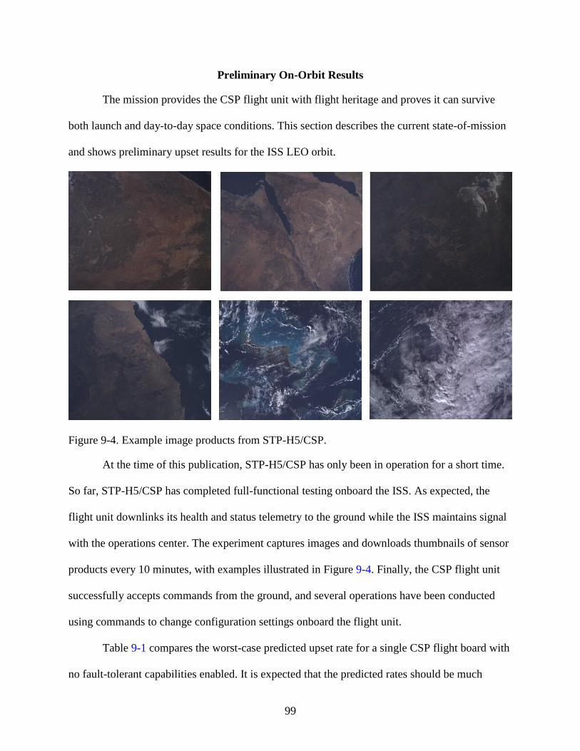
99
Preliminary On-Orbit Results
The mission provides the CSP flight unit with flight heritage and proves it can survive
both launch and day-to-day space conditions. This section describes the current state-of-mission
and shows preliminary upset results for the ISS LEO orbit.
Figure 9-4. Example image products from STP-H5/CSP.
At the time of this publication, STP-H5/CSP has only been in operation for a short time.
So far, STP-H5/CSP has completed full-functional testing onboard the ISS. As expected, the
flight unit downlinks its health and status telemetry to the ground while the ISS maintains signal
with the operations center. The experiment captures images and downloads thumbnails of sensor
products every 10 minutes, with examples illustrated in Figure 9-4. Finally, the CSP flight unit
successfully accepts commands from the ground, and several operations have been conducted
using commands to change configuration settings onboard the flight unit.
Table 9-1 compares the worst-case predicted upset rate for a single CSP flight board with
no fault-tolerant capabilities enabled. It is expected that the predicted rates should be much

100
higher than the actual flight results because the model takes an extremely conservative approach
in every calculation. While data is downlinked from the unit almost continuously and archived
with the operations center, only the data that is stored locally on the ground station was available
for analysis. In 3547.2 hours (147.8 days) of recorded observation, CSP0 has sustained 15 SEFIs
on the ARM side, and 8 SEUs on the FPGA side. Similarly, CSP1 has sustained 10 SEFI on the
ARM side, and 10 on the FPGA side. Notably, on CSPv1’s FPGA side, two of the recorded
upsets were multi-bit upsets.
Table 9-1. CSP Board Upset Rate.
Computer Upsets/Day
CSP Model Prediction 1.9797
CSP0 FPGA 0.0541
CSP1 FPGA 0.0676
CSP0 ARM 0.1014
CSP1 ARM 0.0676
CSP Flight Unit Total 0.2909
101
CHAPTER 10 FAULT-TOLERANT FRAMEWORK FOR HYBRID DEVICES
The main design challenge in developing space computers featuring hybrid system-on-
chip (SoC) devices is determining the optimal combination of size, weight, power, cost,
performance, and reliability for the target mission, while addressing the complexity associated
with combining fixed and reconfigurable logic. This is significant, because with the successful
development and flight of the CSPv1 flight computer, SoC devices in space is a current reality,
and likely to be the future baselined option for next-generation missions. There are many
schemes for fault and error mitigation for both fixed-logic processors and reconfigurable-logic
FPGAs. Our research, however, focuses on developing a fault-tolerant computing strategy that
accounts for the hybrid nature of an SoC device and suggests a strategy that works cooperatively
between both types of architectures. We call this framework HARFT, for hybrid, adaptive, and
reconfigurable fault tolerance.
HARFT Use-Case and Design Overview
HARFT is designed to increase the reliability of space systems targeting SoC devices
composed of multicore CPUs and an FPGA fabric. Our HARFT strategy incorporates fault-
tolerant schemes within both architectures to create an overall robust, hybrid, fault-tolerant
theme for a hybrid device. This section describes the idea use cases for our system and describes
the major components of the framework.
Flight Example
In a science mission, a spacecraft may experience varying levels of radiation from several
sources including the South Atlantic Anomaly (Figure 10-1) and unexpected solar weather
conditions. The system operates by default in the SMP mode. The configuration manager

102
changes the mode dynamically, by reading the current upset rate detected by the scrubber, or
from previously set configurations defined by the ground station.
Figure 10-1. World Map1 displaying proton flux at South Atlantic Anomaly.
HARFT Hardware Architecture
HARFT is subdivided into three main subsystems: the hard- processing system (HPS);
the soft-processing system (SPS); and the configuration manager (ConfigMan). The HPS
consists of the ARM dual-core Cortex-A9 processor and its internal resources. The SPS consists
of programmable-logic elements of the Artix-7 FPGA fabric. Figure 10-2 illustrates a high-level
block diagram of the architecture design.
Hard-Processing System (HPS)
The HPS encapsulates the ARM cores and all the processor resources. The Zynq
architecture does not support lockstep operation in Cortex-A9 cores; therefore, fault-tolerant
strategies on the HPS involve alternating between the SMP and AMP modes. Unfortunately,
there are some limitations to AMP on Xilinx devices. Xilinx documentation notes that since
there are both private and shared resources for each CPU, careful consideration is necessary to
prevent resource contention. Linux manages and controls most shared resources, so it is
1 https://www.spenvis.oma.be/help/background/traprad/traprad.html

103
infeasible to run Linux on both cores of the device simultaneously. CPU0 controlling shared
resources from Linux forces CPU1 to run an operating system with fewer restrictions, such as
FreeRTOS, or custom bare-metal software. Consequently, software developers may have to re-
write applications specifically for CPU1. Xilinx provides AMP-related projects and examples in
their application notes [82-84].
Figure 10-2. HARFT architecture diagram
Soft-Processing System (SPS)
The SPS constitutes a scalable number of PRRs and a static-logic component. Each PRR
can be configured as either a Xilinx MicroBlaze processor or an auxiliary hardware accelerator.
MicroBlazes instantiated in the PRRs operate in lockstep and aggregate as one redundant
processor. The static logic in the SPS contains a hybrid comparator/voter with AXI4 bus
arbitration, reset control, and PR glue logic.
Configuration Manager (ConfigMan)
An essential component of HARFT is the ConfigMan. This component is an independent,
triplicated MicroBlaze system executing operations in lockstep, residing in the static logic of the
programmable-fabric design. The ConfigMan is multipurpose, and can perform operations such

104
as FPGA configuration-memory scrubbing, act as a fault monitor by recording upset events, and
adapt the system by triggering fault-tolerant mode changes. The ConfigMan accesses the FPGA
configuration memory using the AXI Hardware Internal Configuration Access Port
(AXI_HWICAP) IP core (ICAPE2 primitive) and obtains the configuration memory frame ECC
syndrome using a custom AXI-based IP core (FRAME_ECCE2 primitive)2.
ConfigMan Scrubbing
To perform scrubbing, the ConfigMan instructs the ICAPE2 to readback one FPGA
frame. During this readback, the FPGA frame passes automatically through the FRAME_ECCE2
block to compute the ECC syndrome. The ConfigMan reads the FPGA frame from the
AXI_HWICAP buffer into local memory and reads the ECC syndrome from the
FRAME_ECCE2 block. If the syndrome is zero, then there was no error detected and the
ConfigMan proceeds to inspect the next FPGA frame. If the syndrome is nonzero then an error is
present and the syndrome is decoded to determine the word and bit location of the fault (Note:
some errors are detectable but are uncorrectable, which are resolved with a full system reset). An
FPGA frame is corrected by flipping the faulty bit in the frame stored in local memory, as
located by the ECC syndrome. The ConfigMan instructs the ICAPE2 for FPGA frame write-back
to correct the frame in configuration memory. There are 7692 frames in the Zynq-7020 device,
with 101 words per frame, and 32 bits per word. More information detailing these interactions
can be found by Stoddard [85].
2 http://www.xilinx.com/support/documentatio n/sw_manuals/xilinx14_7/7series_hdl.pdf
105
ConfigMan mode-switching mechanics
When the fault-tolerant mode changes, the ConfigMan transfers partial bitstream(s) from
DDR memory to the AXI_HWICAP for PR. A mode switch that increases the number of
processers (e.g., simplex to duplex) requires a reset of the SPS to resynchronize the MicroBlazes
for lockstep operation. However, when the mode switch decreases the number of processors
(e.g., TMR to simplex), no reset is required since the leftover MicroBlazes remain synchronized.
ConfigMan handles PR efficiently when switching modes; only the necessary regions are
reconfigured.
ConfigMan mode switching process
ConfigMan triggers mode switching in two ways. The first is an adaptive-mode switching
based on incoming upsets and recorded faults by the ConfigMan. Since the ConfigMan is
programmable, the user can program various algorithms, such as the windowing strategy in
Jacobs et al. [36]. The second mode switch occurs when the ConfigMan receives a command
from the ground station to place the system into a particular mode for a specific period of time.
An example of this need is for an incoming solar flare, where controllers on the ground can force
the ConfigMan prior to the event to change the fault-tolerant strategy in advance.
SPS Static Logic
The second essential component of HARFT is the SPS-Static Logic (SL). The SPS-SL is,
in essence, a custom IP core that is a hybrid comparator/voter combined with an AXI
Multiplexer. Each of the MicroBlazes from the PRRs includes lockstep signals, which partially
contain the processor state of the MicroBlaze (IP_AXI Instruction Bus and DP_AXI Data Bus).
These signals are inputs to the SPS and multiplexed to the output depending on the current fault-
tolerant mode configuration. Figure 10-3 illustrates the ConfigMan and SPS-SL interactions.

106
Figure 10-3. ConfigMan and SPS-SL architecture diagram.
Fault-Tolerant mode switching
The ConfigMan dynamically switches between three main fault-tolerant modes during
flight operations. These modes refer to a specific configuration of the HPS and the SPS on the
device. Figure 10-4 shows a graphical diagram highlighting the modes.
Figure 10-4. Illustrated fault-tolerant modes diagram.
1. SMP + Accelerators—In this mode, Linux runs on both Cortex-A9 cores in SMP mode.
The PRRs are allocated for hardware acceleration. This mode is the highest-performance
mode; the HPS provides high-performance software execution, accelerating applications
107
by using parallel computing tools, such as OpenMP, and leveraging hardware
accelerators instantiated in the FPGA.
2. AMP + Accelerators—In this mode, Linux runs on only one Cortex-A9 core (CPU0).
Depending on the mission constraints, a real-time operating system (RTOS), such as
FreeRTOS can run on CPU1 for real-time operations. Alternatively, CPU1 can run the
bare-metal equivalent to the Linux CPU0 application in a duplex-like mode, using shared
memory to pass status and health updates. In this scenario, the PRRs can also be allocated
to hardware acceleration.
3. FPGA-Enhanced Fault Tolerance (FEFT)—The final reliability mode refers to a number
of sub-configurations available in the FPGA fabric. The configurations describe
combinations of either MicroBlaze processors or hardware accelerators in the FPGA
fabric (e.g., two MicroBlaze processors in two PRRs, with remaining PRRs as hardware
accelerators). These configurations feature at least one MicroBlaze in a PRR, with the
rest of the PRRs filled with hardware accelerators. If there is more than one MicroBlaze,
they will operate in lockstep. Once this mode engages, the MicroBlaze(s) will take
control of key flight-system applications. This mode is the most reliable; however, the
MicroBlazes operate at a much slower clock frequency than the ARM cores on the HPS
system, and therefore have much lower performance.
Mode switching
The ConfigMan is responsible for switching modes in the FPGA while in the FEFT
mode. To switch between SMP and AMP, a simple script renames the boot files, since each
configuration has different settings for U-Boot and corresponding first-stage boot loader.
Challenges
When designing a system using HARFT, the developer should consider several issues for
a specific mission. We recommend HARFT for those familiar with Xilinx software development,
FPGA development, and Linux development. Configuration for AMP requires designers to
change configuration settings in U-Boot and make modifications to the stand-alone board
support package (BSP) for the first-stage boot loader and additional applications. For this design,
Xilinx provided the custom BSP supporting AMP on the Zynq. Additionally, we do not
recommend switching tool versions in development, since the build process varies drastically in
different Xilinx versions. At present, HARFT uses Vivado 2015.4 and SDK, and we encountered
108
several issues using Vivado including randomly disconnecting signals, and changing parameters
and configurations.
Flight configuration and use model
We designed HARFT to perform optimally in low-Earth orbit (LEO) and environments
that include a typical profile of generally lower upset rates with short bursts of time with
relatively higher upset rates. The limits of HARFT are closely tied with the radiation-effect
limits of the Zynq, and HARFT was specifically structured for the CSPv1flight unit
configuration. Developers may wish to fly the 7-series Zynq with caches disabled due to the
behavior described by Wilson et al. [86]. We also recommend ECC on the DDR memory due to
the need to store bitstreams between configurations. Finally, radiation-hardened or -tolerant
(with multiple images) non-volatile storage is recommended, so that boot images for SMP and
AMP modes remain uncorrupted.
Experiments and Results
This section discusses experiments and HARFT prototype development to evaluate our
ideas and architectural design. First, we discuss general experiments, which verify the limitations
of the processor modes and expected behavior on a testbed. These experiments show the strong
need for adaptive flexibility in a changing radiation environment. Next, this section provides a
brief overview of the radiation-effects methodology introduced in Chapter 5 that determines the
estimated effectiveness of our proposed method. Finally, we describe the developed prototype
for HARFT, highlight conducted metrics and benchmarks, show the FPGA resource utilization
and scrubber performance, and discuss expected HARFT behavior due to radiation effects.
Processor Experiments
We examine several processor tests as part of the problem-determination phase of this
research and for familiarization with AMP configuration on the Zynq. These tests consist of

109
configuring the operating system for each test, and then halting one of the cores or corrupting the
program counter (PC) in order to crash the program using the built-in debugging tools.
Basic SMP experiment
This simple experiment confirms that unexpected errors (which could be the result of an
SEE) in one of the cores in SMP mode will lead to a system crash. This outcome is significant
because if SMP does not crash from an upset in one of the cores then AMP would not be
necessary. Xilinux (Xilinx Linux) ran across both CPU0 and CPU1 in SMP mode. We conducted
10 runs for each test (halting and crashing) on both processing cores. When one of the cores halts
the system, the behavior is not deterministic, and occasionally, in several tests, the system would
continue to operate, while in others the system suffered a crash. When the PC of one of the cores
changes to an unexpected address, the system always results in a crash.
Basic AMP experiment
This experiment shows the resilience of an AMP-configured design, and establishes that
it performs as expected on a hardware testbed. In this experiment, CPU0 runs Xilinux, CPU1
runs a bare-metal application, and a MicroBlaze runs another bare-metal application. Once again,
we conducted 10 runs for both types of tests on each of the processors. When either of the
processor cores halts, the other core continues to function nominally, and the MicroBlaze
remains unaffected. Similarly, when one of the cores has its PC set to an unexpected address, the
other core, as well as the MicroBlaze, continues operation as intended.
Reliability Modeling
To analyze HARFT, we create a dynamic fault-tree model as described in Chapter 5 as
part of a CubeSat reliability methodology. This methodology relies on tools including CRÈME
and PTC Windchill Predictions to build a model of the processing system and programmable
logic.
110
CRÈME96
CRÈME96 is a state-of-the-art tool for SEE-rate prediction. The tool allows the user to
generate upset rates for individual components in varying Earth orbits. CRÈME also allows a
user to simulate different conditions of an orbit as it relates to solar weather and galactic cosmic
rays.
Modeling methodology
The research in Chapter 5 provides a methodology for estimating the reliability of
SmallSat computers in radiation environments. Our analysis uses the microprocessor submodule
model to show upset rates of the programmable-logic and processing-system portions of the
Zynq. In this submodule, each mode has a constructed dynamic fault tree (DFT) that models the
Zynq architecture. For our analysis, we use proprietary Weibull curves (inputs into CRÈME)
gathered for the main Zynq components in the processing system and programmable logic from
radiation test reports. CRÈME then generates the upset rates based on the specified orbit. The
DFT-submodule “basic events” have the previously calculated CRÈME upset rates as inputs.
HARFT Prototype Description
As a proof-of-concept for HARFT, we create a prototype design using a Digilent
ZedBoard containing the Zynq-7020 SoC. While our HARFT description encompasses a number
of possible configuration options, this section describes a single configuration that we built as a
prototype.
HPS configuration
In the prototype, the HPS is configured with a ZedBoard running a branch of Xilinx
Linux. U-Boot and the device tree are modified to add the necessary design-specific drivers,
force single-processor operation (for AMP), and restrict DDR memory access available for the
111
system (DDR memory must be reserved for the MicroBlaze and to store configurations). CPU1
runs a simple bare-metal application or FreeRTOS.
SPS configuration
HARFT supports any number of desired PRRs within the resource constraints; for this
prototype, we selected three PRRs. With three PRRs, possible modes for FEFT include Simplex,
Duplex, and Triplex. The MicroBlazes are instantiated within the design and configured for
maximum performance without caches or TLBs.
ConfigMan configuration
The ConfigMan maintains a user-configurable number of thresholds to switch modes. If
the ConfigMan detects a number of faults exceeding a threshold while scrubbing, it triggers a
new configuration.
Additional hardware configuration
The prototype contains cores that would not be needed in a flight configuration including
UARTS, PMOD UARTS, LED core, and switches. We place these cores explicitly for project
debugging and testing.
Table 10-1 and Table 10-2 list the resource utilization for the three PRRs and the
complete prototype on the device. Figure 10-5 shows the entire placed and routed design. The
cyan highlight denotes the ConfigMan, the light purple denotes the SPS-SL, and the light blue
denotes the hardware test cores (UARTs, LEDs, including bus logic etc.). Lastly, the yellow,
blue, and red regions represent the three PRRs.
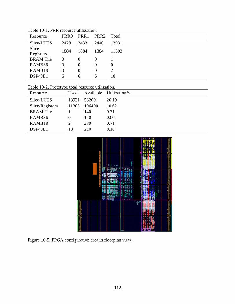
112
Table 10-1. PRR resource utilization.
Resource PRR0 PRR1 PRR2 Total
Slice-LUTS 2428 2433 2440 13931
Slice-
Registers 1884 1884 1884 11303
BRAM Tile 0 0 0 1
RAMB36 0 0 0 0
RAMB18 0 0 0 2
DSP48E1 6 6 6 18
Table 10-2. Prototype total resource utilization.
Resource Used Available Utilization%
Slice-LUTS 13931 53200 26.19
Slice-Registers 11303 106400 10.62
BRAM Tile 1 140 0.71
RAMB36 0 140 0.00
RAMB18 2 280 0.71
DSP48E1 18 220 8.18
Figure 10-5. FPGA configuration area in floorplan view.

113
HARFT Prototype Analysis
For this analysis, we calculate upset rates for LEO. These rates show the reliability of
each mode respective to one another. The reliability of these modes in different orbits can be
extrapolated from the relationship between the modes established from LEO results.
Figure 10-6 and Figure 10-7 show the reliability of the main modes of HARFT.
Additionally, a reliability curve representing the FPGA, if every bit on the device is considered
essential, is provided as a reference and is labeled “FPGA” in the graph. For the FEFT-mode
calculations, we assume that any upset temporarily interrupting the processor is a failure. Using
this model, FEFT-Duplex and FEFT-Simplex show similar rates because a single upset would
cause either to fail, however, in practice FEFT-Duplex would detect the error, while FEFT-
Simplex would continue until the device failed or the scrubber detected the error.
Figure 10-6. HARFT reliability with L2 cache disabled.

114
Figure 10-7. HARFT reliability with L2 cache enabled.
For these calculations, Xilinx guidelines state that 10% of configuration-memory bits are
significant in any design. For the model, this fraction of each PRR and the static area is
calculated and scaled to 10% of the total sensitive device-configuration bits.
Results demonstrate that, as expected, level-two (L2) cache has a significant effect on the
overall reliability of the system. The L2 cache is responsible for a majority of upsets on the
processing system, therefore, Figure 10-6 shows the reliability of all HARFT system modes with
L2 cache disabled, while Figure 10-7 shows the same but with L2 cache enabled. Figure 10-7
shows that the most reliable mode for the system is the FEFT-TMR mode. In the chart, this
reliability is near one. The result is due to the low number of faults expected in LEO, while the
scrubber correction rate is extremely high as seen in Table 10-3, even under the worst-case
scrubbing scenario (needing to read the entire FPGA and then writing to the correct frame).
Figure 10-6 shows AMP is more reliable than SMP, while both are slightly more reliable than
FEFT-Duplex and FEFT-Simplex.
As cited above, Figure 10-7 shows the same LEO example with L2 cache enabled. Since
the L2 cache is responsible for the dominant portion of errors, the reliability of the modes is re-
ordered. AMP and SMP modes have the worst reliability compared to all of the FEFT modes.

115
Table 10-3. FPGA scrubbing duration.
Operation Duration (sec)
Readback (Entire FPGA) 14.5246
Readback (Frame) 0.001888
Writeback (Entire FPGA) 19.9478
Writeback (Frame) 0.002593
Table 10-4. Computational density device metrics.
Processor Computational Density (GOPS)
INT8 INT16 INT32
ARM Cortex-A9 Dual-Core 32.02 16.01 8.00
ARM Cortex-A9 Single-Core 16.01 8.00 4.00
MicroBlaze 0.125 0.125 0.125
HARFT Performance Modeling
We calculate device metrics, as described by Lovelly [61], using the theoretical
maximum performance for each of the three modes, illustrated in Table 10-4. While floating-
point calculations are available, this table only displays integer operations for brevity and to
compare with benchmark results, which are integer only. It should be noted that, while the SMP
mode may have lower reliability, it has dramatically increased performance over the FEFT
mode.
To provide an alternate view of processor performance, we benchmark with CoreMark
the featured processors. CoreMark is a benchmark developed by the Embedded Microprocessor
Benchmark Consortium with the goal of measuring the performance of embedded-system CPUs.
Table 10-5 displays the results of the benchmarks and confirms the theoretical trends calculated
for device metrics. We note that the L2 cache does not appear to improve the performance of the
CoreMark benchmark. This result is explained by the benchmark's low memory usage versus the
32KB level one (L1) instruction and data caches. The data and bss segments amount to about
16KB, which is about half of the capacity of the L1 data cache. The text segment is about 67KB,
116
which is larger than the size of the L1 instruction cache and may incur a slight performance
penalty due to cache misses justifying the differences in the results.
Table 10-5. Zynq processors’ CoreMark benchmarking performance.
Configuration Iterations/sec
Single-Core ARM with Caches Enabled 1980.2979
Single-Core ARM w/o L2 Cache 1971.2254
Single-Core ARM w/o Caches 116.9640
FPGA soft-core MicroBlaze 9.5975
We compile the benchmark used in Table 10-5 with "PERFORMANCE_RUN"
configuration and -O2 compiler optimizations. The number of iterations tested varied: 1000 for
MicroBlaze, 100,000 for ARM. This discrepancy results from the enormous time requirement for
the MicroBlaze to execute 100,000 iterations. The precision error is minimal at over 10 seconds
of execution.
There are no specific application accelerators developed thus far for the prototype. Since
the amount of speedup varies with application and hardware design, we assume that each PRR
accelerator adds 100 iterations/sec to highlight and establish the general-profile trends for the
reliability modes.
Figure 10-8 shows the reliability vs. performance of different modes depending on
varying fault rates with L2 cache disabled. We estimate the calculations for SMP mode by
doubling the single-core results of Table 10-5 (the CoreMark benchmark is single-threaded).
The graph highlights the Pareto optimal line for the varying configurations and indicates that it is
only useful to switch between AMP, SMP, and FEFT-Triplex when L2 cache is disabled.

117
Figure 10-8. Upsets per day vs. performance with L2 cache disabled.
Figure 10-9. Upsets per day vs. performance with L2 cache enabled
Figure 10-9 shows the same results with L2 cache enabled. The HPS shows drastically
higher performance, however, it is much more prone to upsets. FEFT-Duplex and FEFT-Simplex
are more viable in this configuration since they provide higher reliability than the HPS modes
while still maintaining higher performance than FEFT-Triplex. This chart illustrates the flexible
trade space for switching modes on a prototypical LEO mission.
Framework Status and Future Considerations
This chapter presents a novel, hybrid, fault-tolerant framework, HARFT, designed
specifically to adapt to the dual architecture capabilities and needs of SoC devices. We built a

118
specific HARFT configuration to test and verify the structural and design features as proof of
concept. HARFT features three dynamically configured modes: (1) SMP + Accelerators; (2)
AMP + Accelerators; and (3) FEFT + Sub-configurations. The benchmarking and reliability
analysis list these modes in order of the highest to lowest in performance, and from lowest to
highest in reliability. A custom-designed IP core, ConfigMan, simultaneously scrubs the FPGA
for faults, determines upset rate, and dynamically reconfigures the fault-tolerant mode. Our
experiments in this paper verify the functionality of the prototype, especially with regard to the
behavior of the processing system modes in AMP and SMP. The analysis highlights that, since
L2 cache is prone to upsets, the HARFT mode selection changes, depending on if the mission
designer enabled or disabled the L2 cache. Finally, with these methods on a hybrid SoC, a
spacecraft may adapt to changing environmental conditions in order to achieve a high level of
both performance and reliability for each mission scenario.
There are several features that we propose to improve the functionality and performance
of HARFT, which could be investigated in future development. Several of these additional
features are not complex; however, we did not include these features due to time restrictions.
Key additions include dynamic recovery of system by working processors, checkpointing of
system state, optimizing timing and FPGA performance, and finally, the use of machine
intelligence in ConfigMan for mode switching.

119
CHAPTER 11 CSP SUCCESSORS
The CSP concept is not restricted with respect to spacecraft size (i.e. CubeSat vs. large
satellite) or limited to a processing device (e.g. Xilinx Zynq); it is a design concept that can be
scaled and expanded to many scenarios. This section describes alternative application of the CSP
concept to other platforms beyond the CSPv1.
µCSP and Smart Modules
The CSP team decided to address processing and networking needs of future smart
modules (e.g., smart sensors, smart actuators), as well as improve computing capability for
lower-end CubeSats. Following the design principles proposed for hybrid space computing in
Chapter 4 the CSP team developed a new design known as µCSP [90]. Like CSPv1, µCSP is
designed with a hybrid mix of commercial and rad-hard components supplemented with
techniques in fault-tolerant computing. µCSP also features a hybrid-processor architecture
(Microsemi’s SmartFusion 2 M2S090), with a mix of fixed and reconfigurable logic (ARM
Cortex-M3 processor combined with a Flash-based FPGA fabric), but all in a smaller form factor
with lower SWaP-C. µCSP is smaller than a credit card and designed to integrate into (but not be
limited to) 1U SmallSat form factors. This section describes the design decisions and concepts
for the development of both µCSP and Smart Modules.
Concepts of Smart Modules
Despite CubeSats having a common mechanical structure, the internal hardware design
may drastically differ between implementations. Many CubeSats that are created are one-off
designs, specific to each mission and its requirements. While these designs are different, there
are design commonalities that must be present to guarantee functionality (e.g., power,
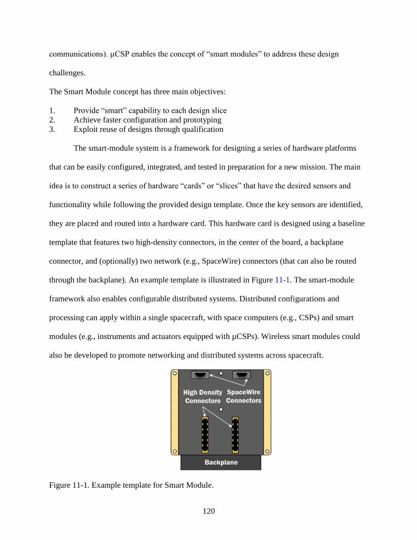
120
communications). µCSP enables the concept of “smart modules” to address these design
challenges.
The Smart Module concept has three main objectives:
1. Provide “smart” capability to each design slice
2. Achieve faster configuration and prototyping
3. Exploit reuse of designs through qualification
The smart-module system is a framework for designing a series of hardware platforms
that can be easily configured, integrated, and tested in preparation for a new mission. The main
idea is to construct a series of hardware “cards” or “slices” that have the desired sensors and
functionality while following the provided design template. Once the key sensors are identified,
they are placed and routed into a hardware card. This hardware card is designed using a baseline
template that features two high-density connectors, in the center of the board, a backplane
connector, and (optionally) two network (e.g., SpaceWire) connectors (that can also be routed
through the backplane). An example template is illustrated in Figure 11-1. The smart-module
framework also enables configurable distributed systems. Distributed configurations and
processing can apply within a single spacecraft, with space computers (e.g., CSPs) and smart
modules (e.g., instruments and actuators equipped with µCSPs). Wireless smart modules could
also be developed to promote networking and distributed systems across spacecraft.
Figure 11-1. Example template for Smart Module.

121
The two high-density connectors shown are used to attach our new low-power, hybrid
computer, µCSP, to the module. The card can also plug into a backplane board with the
backplane connector. This backplane connector provides power, ground, and bus
communications to each of the modules. A board connection and mating diagram is displayed in
Figure 11-2. Finally, the two SpaceWire connectors link each module to the board above and
below it, forming a ring network as seen in Figure 11-3.
Figure 11-2. Integration and mating with a Smart Module.
The µCSP present on each card provides a smart module with low-power processing.
µCSP can scale its power based upon the processing required for the node. One major benefit
from this design is that once a hardware card is developed, it can be placed anywhere in the
stack, due to the configurability of the connections. Once drivers and software are developed for
the card, the card is portable and can be reused to rapidly prototype or assemble entire flight
designs.
Example devices are elaborated by NASA Ames [59] with examples summarized in
Table 11-1 (e.g. Smart Thruster card).

122
Figure 11-3. Ring network connection for Smart Module.
As the “brain” for each smart module, µCSP allows designers to focus on their
application and not on low-level implementation. After more of these hardware cards are
developed, an inventory of designs is enabled that can be taken straight from “shelf-to-
spacecraft.”
Table 11-1. Example components for Smart Modules
Subsystem Example Components
Power Solar Cells
Batteries
Power Generator
Propulsion Thruster
Solar Sail
Communication Transmitters
Flight Terminal
Instruments Optical Spectrometer
Photometer
Particle Detector
Attitude Determination and Control Reaction Wheels
Magnetorquer
Control Moment Gyros
Star Track
Sun Sensors
GPS Receiver and Antennas

123
µCSP Hardware Architecture
µCSP is designed to attach to a 1U CubeSat form-factor board (Smart Module), through
two high-density connectors on the bottom. µCSP is roughly the size of a credit card (1.5" x
2.8”) and 63 mils thick. An isometric view of the prototype of this board is provided in Figure
11-4. All components for the board were purchased for an industrial temperature grade to support
a temperature ranging from –40°C to +85°C.
µCSP can operate at 50 to 100 mW in a low-power standby mode and can be awakened
with an interrupt. The nominal operational mode is estimated at 500 to 800 mW. Finally, we
estimate maximum power with full utilization of the ARM Microcontroller Subsystem (MSS)
and FPGA fabric at around 1 Watt.
Figure 11-4. µCSP computer board testing prototype.
This new, small space computer has several main communication interfaces and I/O pins
available. µCSP provides over 40 differential pairs (that can also be configured for single-ended
operation). The board features two interfaces each for UART, I2C, and SPI (4 slave-selects
each). With the PHYs placed on the Smart Module, the µCSP can support one CAN and one
USB2.0 interface. Our board has an Ethernet PHY to support 100 Mb/s connections, as well as 1
lane of PCI-Express. Finally, a JTAG interface is included to program and configure the device.

124
The inexpensive, commercial Emcraft SmartFustion2 System-on-Module (SoM)
development platform can be fully interfaced with any designs following the Smart Module
template. This approach allows Smart Module designs to be tested without a µCSP, solely using
the Emcraft SoM, providing a cost-effective means of creating a ground-system testbed and
performing verification. µCSP exhibits near complete pin compatibility with the SoM’s
evaluation board, albeit with some minor modifications. Finally, there are future plans for
“carrier cards” with commercial components, which can be placed into the radiation-hardened
footprints to assemble a commercial µCSP.
Table 11-2. Major components of µCSP.
Device Vendor Commercial / Radiation Hardened/Tolerant
Switching
Regulators
3D-Plus Radiation-Hardened
NOR Flash Aeroflex Radiation-Tolerant
Watchdog
Timer
Intersil Radiation-Hardened
SmartFusion2 Microsemi Commercial
LPDDR Intelligent
Memory
Commercial
Adhering to the CSP concept, µCSP includes both commercial and radiation-hardened
subsystems. Commercial components are featured for performance with low SWaP-C, and are
closely managed by radiation-hardened or -tolerant components. Table 11-2 shows the key
subsystem components in µCSP.
Microsemi’s SmartFusion2 is a powerful, hybrid device featuring an ARM Cortex-M3
processor combined with a flash-based FPGA fabric. µCSP employs the m2s090 model, which is
the most capable of the SmartFusion2 devices in a 484-pin package. Some key characteristics of
the selected device are listed in Table 11-3 and Table 11-4.

125
Table 11-3. SmartFusion2 ARM specifications.
ARM Specifications
Maximum Clock Frequency 166 MHz
Instruction Cache 8 KB
Embedded SRAM (eSRAM) 64 KB
Embedded Nonvolatile Memory
(eNVM)
512 KB
Table 11-4. SmartFusion2 FPGA specifications
FPGA Specification
Logic Elements 86,184
Math Blocks 84
SRAM Blocks 2074
µCSP Software Architecture
The featured technology on µCSP, the SmartFusion2 SoC, includes the ARM MSS
(Cortex-M3) as its built-in hardcore processor. The Cortex-M3 was specifically developed to
provide high performance at low power for microcontroller-type apps. This flexible platform can
easily support two popular operating systems. The first supported is uClinux, which is an
embedded Linux/Microcontroller project that ports Linux to systems that do not have a Memory
Management Unit (MMU). U-boot can be installed on the on-chip, non-volatile memory to load
uClinux and the root filesystem1. For apps that require determinism in execution, the Real-Time
Operating System (RTOS) known as FreeRTOS can be booted to the Cortex-M32.
Future work for µCSP involves integrating NASA Goddard’s open-source, flight-system
software, Core Flight Executive (cFE), and key supporting libraries and applications found in
their Core Flight System (cFS) to the SmartFusion2 in uClinux. Depending on availability and
progress, cFS developers have a project in progress called micro-cFE to develop a minimal cFS
1 http://www.uclinux.org/
2 http://www.freertos.org/SmartFusion2_RTOS.html
126
flight-software framework specifically targeting small payloads and CubeSats that could be used
in µCSP’s build system3.
µCSP Fault-Tolerant Architecture
µCSP includes fault-tolerance methods beyond its radiation-hardened and -tolerant
components. The FPGA fabric of the SmartFusion2 is flash-based, which significantly differs
from SRAM-based counterparts. While SRAM-based FPGAs are frequently affected by SEEs,
the reconfigurable flash cell is resilient against SEEs [87], which makes flash-based FPGAs
particularly useful for space-based apps.
µCSP includes a built-in hardware watchdog timer in the SmartFusion2, in addition to the
external, hardened watchdog device by Intersil. This external watchdog is critically important to
ameliorate radiation concerns for the operation of the SmartFusion2 in space. A whitepaper by
Microsemi [88] states:
“… tests indicate that the IGLOO2 FPGAs and SmartFusion2 FPGAs encounter non-
destructive latch-ups in heavy ion radiation testing, at energy levels low enough to cause concern
in low earth orbit (LEO) space applications”
This interim report was published in 2014, but was further investigated with additional
testing by Dsilva [89]. In that report, Single-Event Functional Interrupt (SEFI) behavior was
more closely studied and four different recovery mechanisms were studied to recover the MSS if
a SEFI occurred. These mechanisms included: (1) the MSS recovers by itself through time-out;
(2) the MSS built-in watchdog recovers; (3) reset is issued to recover the MSS; (4) a full power
cycle needed to recover. A full power cycle is required for certain components of the MSS for
recovery, and consequently the Intersil hardware watchdog on µCSP will perform this reset
3 http://www.coreflightsystem.org
127
function when triggered by lack of heartbeat from the SmartFusion2. Since watchdog reset of the
system may be required under certain upset conditions, µCSP is only recommended for missions
and flight applications where 100% availability is not a driving requirement.
SmartFusion2 also has several built-in reliability functions described by Microsemi4.
Single Error Correct Double Error Detect (SECDED) protection can be turned on for several
resources including Ethernet buffers, CAN message buffers, eSRAM, USB buffers, PCIe buffers,
and DDR memory controllers. There are also buffers with SEU-resistant latches including DDR
bridges, instruction cache, MMUART FIFOs, and SPI FIFOs. SmartFusion2 also has a built-in,
self-test (BIST) mechanism that can be used to check status of the device automatically upon
power-up or on demand. The BIST checks the contents of nonvolatile configuration memory,
security keys, settings, and ROM memory pages. Lastly, there is no external configuration
memory required to program and configure the device because it retains its configuration during
a power cycle. The flash fabric is resistant to power “drop outs” during configuration, which
would cause reliability issues for traditional SRAM-based FPGAs.
Smart Module Designs
In addition to the design of µCSP, several smart modules are in various stages of
development and planning to showcase the versatility of µCSP, act as initial examples of types
of smart modules to be created, and demonstrate a proof-of-concept, distributed space system. A
CubeSat can be rapidly constructed once a library of validated designs has been generated for
different smart module cards. This framework will significantly improve assembly and
preparation for CubeSat missions and allow nearly identical spacecraft to be rapidly created. This
system will allow configuration of a computing swarm with functionality distributed across
4 http://www.microsemi.com/products/fpga-soc/reliability/sf2-reliability

128
multiple CubeSats. The framework will also allow fast construction of replacement spacecraft in
the event of failures.
Another benefit of adhering to the Smart Module concept is reduction of extensive wiring
that is found in some spacecraft. Figure 11-5 illustrates an example of required wiring for a 6U
CubeSat. Smart modules place the processing intelligence closer to the sensor and actuators and
employ a unified communications system, therefore reducing the bulk of the wiring for power
and common communication interfaces.
Figure 11-5. Example of 6U CubeSat wiring harness.
The reduction of wiring has a multitude of benefits:
1. Reduces weight of spacecraft, thereby reducing cost by extension.
2. Decreases integration and test time involved with building, assembling, and testing the
wiring harness.
3. Simplifies debugging and emulation of a system; since each subsystem will be composed
of the same uCSP, there will be more design reuse and engineers will no longer have to
be familiar with multiple interface standards.
129
µCSP Achievement Highlights
There is a clear need for a high-performance computer for future CubeSat missions that
are limited by highly limited power systems. µCSP is a small, low-cost, and low-power space
computer designed to provide increased capability for SmallSat missions that need higher
performance and reliability despite severe resources constraints in size, weight, power, and cost.
Additionally, µCSP enables the realization of Smart Module in distributed space systems, which
can provide fast configuration of spacecraft for missions, improve productivity, and reduce
mission-specific redesign.
µCSP follows our original CSP Concept and features reconfigurable and multifaceted
hybrid computing, with a hybrid-system and a hybrid-processing architecture in a small form
factor. The µCSP hardware design, combined with a variety of fault-tolerant computing
techniques, running flight-system software, provides users with an optimal combination of
performance, energy efficiency, and reliability to satisfy a variety of space missions. Fast
assembly and replication of CubeSats is a key milestone in creating a distributed-computing
cluster for space, with functions distributed across different CubeSats, as well as developing
replacements for failed modules in the swarm.
SuperCSP and STP-H6/SSIVP
With the success of CSPv1, a survey was conducted to determine the next research step.
Polling key aerospace government and industry contacts, the general response was to extend the
capability of the CSPv1 design by developing a cluster of CSPv1 boards working cooperatively,
which focuses upon scalability of a well-tested board, instead of creating a new unverified
design. These groups described a need for a multiple-processor system featuring several boards
for both redundancy and to achieve performance targets, combined with a high-bandwidth
interconnect. Taking this need under consideration, the CSP team proposed to demonstrate a

130
networked cluster of space computers that can execute complex apps to bring ground-based
supercomputing capabilities to high-end space customers. The CSP team submitted several
proposals to: develop, demonstrate, and evaluate next-generation technologies for space
supercomputing, featuring image and video processing, with parallel, distributed, and
reconfigurable computing.
In December 2016, the CSP team was selected to fly the proposed experiment on STP-H6
as the Spacecraft Supercomputing for Image and Video Processing (STP-H6/SSIVP) mission. To
begin networking experimentation and to provide an initial development platform, the CSP team
developed the SuperCSP. The SuperCSP is an extensive evaluation card, or backplane, that
consists of four slots fitting CSPv1 boards. This design supports JTAG, USB-UART, Ethernet,
SpaceWire, and a variety of I/O to each of the connected boards. This system is shown in Figure
11-6.
Figure 11-6. SuperCSP backplane with 4 CSPv1s.
SSIVP is a novel experiment to advance the state of the art in space computing by
demonstrating the use of high-performance computing (HPC) techniques on a space platform.
SSIVP will feature several novel flight computers working as a cluster. The mission hardware
configuration consists of a 3U flight box. 1U of the box houses dual Camera Link cameras. The

131
remaining 2U features four flight-qualified CSPv1 Rev. B boards as compute nodes, one CSPv1
Rev. C as head node for cluster management, a µCSP board, a power board, an interface board,
and backplane interconnect. The deconstructed assembly is featured in Figure 11-7. Inter-CSP
communication is facilitated by high-performance, point-to-point links with networking protocol
(e.g., SerDes, SpaceWire) defined and configurable in the FPGA. The software configuration
incorporates NASA Goddard’s flight-software framework, core Flight System. However, the
cFE software bus supporting communication between all CSPv1 nodes has been redesigned with
innovative modifications. The communication backend of the original bus is replaced with OMG
Data Distribution Services (DDS) to support inter-node, publish-subscribe functionality. The
primary objective for this mission is to demonstrate and evaluate a novel framework for space-
based supercomputing with networked system-on-chip devices emphasizing high performance
and reliability. The completed flight unit prepared for environmental testing is pictured in Figure
11-8.
Figure 11-7. Deconstructed view of STP-H6/SSIVP flight box.
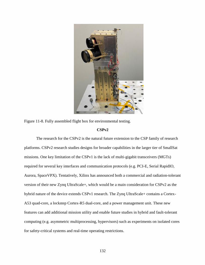
132
Figure 11-8. Fully assembled flight box for environmental testing.
CSPv2
The research for the CSPv2 is the natural future extension to the CSP family of research
platforms. CSPv2 research studies designs for broader capabilities in the larger tier of SmallSat
missions. One key limitation of the CSPv1 is the lack of multi-gigabit transceivers (MGTs)
required for several key interfaces and communication protocols (e.g. PCI-E, Serial RapidIO,
Aurora, SpaceVPX). Tentatively, Xilinx has announced both a commercial and radiation-tolerant
version of their new Zynq UltraScale+, which would be a main consideration for CSPv2 as the
hybrid nature of the device extends CSPv1 research. The Zynq UltraScale+ contains a Cortex-
A53 quad-core, a lockstep Cortex-R5 dual-core, and a power management unit. These new
features can add additional mission utility and enable future studies in hybrid and fault-tolerant
computing (e.g. asymmetric multiprocessing, hypervisors) such as experiments on isolated cores
for safety-critical systems and real-time operating restrictions.

133
CHAPTER 12 CONCLUSIONS
This dissertation introduces the CSP concept, a new approach for hybrid, reconfigurable
space computing that has the capacity to adaptively optimize for performance, reliability, and
power to suit a variety of mission needs. The purpose of the CSP concept is not constrained to
the production and design of the first flight board (CSPv1); it strives to foster the overarching
concept of hybrid space computing. SHREC is engaging in ongoing studies to determine which
components and features could be added to develop an even more robust space-processing
platform with CSPv2. Through the CSP concept, SHREC endorses a design framework that
embraces the best features of rad-hard and commercial designs, as well as fixed and
reconfigurable devices to achieve a compelling middle-ground solution for space computing.
To validate and analyze configurations and designs derived with the CSP concept, this
dissertation presents the SmallSat computer reliability modeling methodology. The methodology
provides a straightforward series of steps to create reliability metrics for an entire system design
that allows configurations to be compared to each other. The methodology incorporates on state-
of-the-art reliability tools and modeling software to provide estimates of system behavior in
different environmental conditions. In preparation for flight, the CSPv1 design was analyzed
with the methodology to assist in making critical modifications and estimate reliability of the
design.
Realization of the CSP concept for flight has been fully achieved with the STP-H5/CSP
mission. This mission serves as a technology readiness level (TRL) advancement and space
validation for the CSPv1 board and its supporting software. In this research mission, we have
successfully demonstrated a transition from TRL1 to TRL9 on a design for SmallSat
applications. For the foreseeable mission duration, valuable radiation data and upset rates to the
134
CSPv1 boards will be collected to gain further insight into hybrid-space design leading to future
designs and improvements. STP-H5/CSP regularly sends down health and status data along with
thumbnail images taken periodically by the image sensor. Downloaded logs and received packet
playback features of the ground software allow the CSP team to analyze the behavior of STP-
H5/CSP. So far in the mission, the observed upset rates due to radiation have been dramatically
lower than predicted rates generated from the orbital model. The STP-H5/CSP flight box is the
first venture into exploring the capabilities of the CSPv1 flight board and the CSP concept in a
real space environment.
Finally, with the success of the STP-H5/CSP mission, this dissertation highlights the
challenges of fault-tolerant strategies for hybrid designs. This dissertation shows the adaptation
and enhancement of a previous CHREC center research project known as Reconfigurable Fault
Tolerance (RFT)), into the Hybrid, Adaptive, Reconfigurable Fault Tolerance (HARFT)
framework, designed specifically to provide a system-level, fault-tolerant framework for SoC-
based designs. A prototype for this design was developed suitable for integration with the CSPv1
design. Final plans for this work involve validating this hybrid fault-tolerant framework in space
as an upload to STP-H5/CSP or incorporated as part of STP-H6/SSIVP.
In conclusion, this dissertation presents a new concept for space-system hybrid designs, a
methodology for analyzing these hybrid designs, and finally, a novel framework to employ fault-
tolerance over the hybrid designs. The success of STP-H5/CSP is the preliminary catalyst
proving these concepts and provides examples that will help advance studies for the next
generation of space processors for even more advanced missions.

135
APPENDIX
SPACE PROCESSORS
Table A-1. SmallSat processors and Single-Board Computers
Device Vendor Device Type SBC Vendor SBC Missions
Actel ProASIC3 FPGA Xiphos Q7, Q6 ACES RED #1, GHGSat-D
Atmel AT91SAM7A1 Microcontroller GomSpace Nanomind A712D STRaND-1
Atmel AT697E Microprocessor SwRI SC-SPARC8 Instrument Controller JUNO, Solar Orbiter, MMS
Atmel AT91SAM9G20 Microcontroller Tyvak Intrepid INCA
Atmel AT32UC3C Microcontroller GomSpace Nanomind A3200 GOMX-3, Dellingr
Atmel AT91SAM9G20 Microcontroller ISIS OBC QB50p1 p2, IL-02, TW-01, CN-
01, BE-06, PEASSS
Atmel ATmega329P Microcontroller NanoSatisfi Inc. ArduSat Kit ArduSat 1
Broadcom BCM2835/6/7 SoC RaspberryPi.org Raspberry Pi Modules Pi-Sat, NODeS
Cobham UT699 Microprocessor SEAKR SBC Orion VPU
Cobham Gaisler LEON3FT Microprocessor SDL MODAS Bus Interface Module
Cobham Gaisler GR712RC Microprocessor SwRI Centaur CYGNSS, CuSP, NASA Mission
Avionics, Undisclosed
Cobham UT699 Microprocessor SwRI FT Spacecraft/Instrument
Controller
JUNO, FERMI, Kepler, DoD
Mission
Freescale P2020 Microprocessor Space Micro Proton400k ORS-1
Microchip PIC24FJ256GA110 Microcontroller Pumpkin PSPM D MiRaTA, MicroMAS-1,
FIREBIRD-I
Microchip PIC24F256GB210 Microcontroller Pumpkin PSPM E
Microchip PIC24FJ256GA110 Microcontroller Pumpkin PPM D1 Caerus/Mayflower, DICE-1,
DICE-2, Aeneas
Microchip dsPIC33FJ256GP710 Microcontroller Pumpkin PPM D2 CINEMA
Microchip ATmegaS128 Microcontroller Undisclosed Undisclosed Undisclosed
Microsemi SmartFusion 2 SoC Clyde Space OBC
Microsemi SmartFusion 2 SoC NSF SHREC ctr. µCSP STP-H6/SSIVP
Nvidia Tegra SoC Innoflight TFLOP Undisclosed
NXP MPC8548E Microprocessor Aitech SP0 MUSES
NXP MPC7457 Microprocessor SEAKR G4 Artemis TacSat 3
NXP MPC8548E Microprocessor SwRI High-Performance SBC Undisclosed
Silicon Labs EFM32GG280F1024 Microcontroller CubeSpace CubeComputer
Silicon Labs C8051F120 Microcontroller Pumpkin PSPM B
Silicon Labs C8051F120 Microcontroller Pumpkin PPM B1 QbX1, QbX2
Sitara AM3359AZCZ100 Microprocessor BeagleBoard.org BeagleBone Black
(Rev C) RADSat, ANDESITE, TRYAD
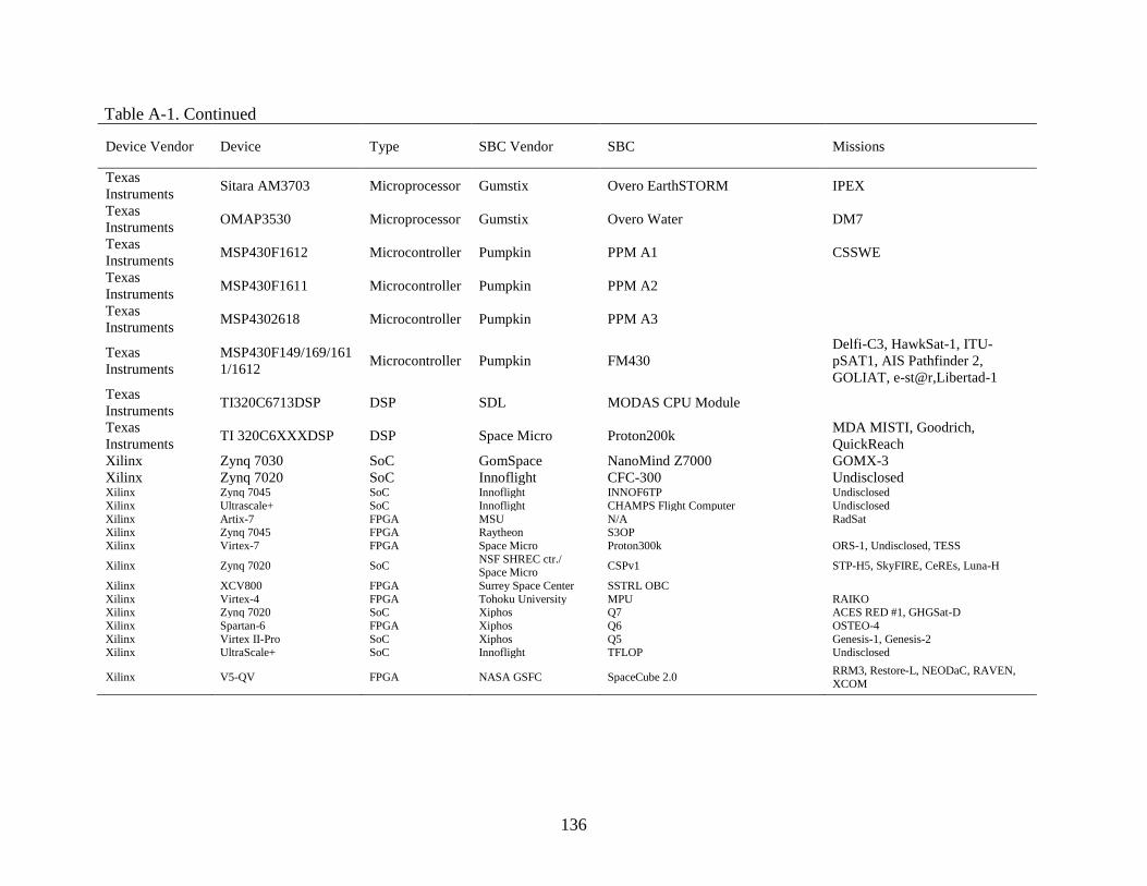
136
Table A-1. Continued
Device Vendor Device Type SBC Vendor SBC Missions
Texas
Instruments Sitara AM3703 Microprocessor Gumstix Overo EarthSTORM IPEX
Texas
Instruments OMAP3530 Microprocessor Gumstix Overo Water DM7
Texas
Instruments MSP430F1612 Microcontroller Pumpkin PPM A1 CSSWE
Texas
Instruments MSP430F1611 Microcontroller Pumpkin PPM A2
Texas
Instruments MSP4302618 Microcontroller Pumpkin PPM A3
Texas
Instruments
MSP430F149/169/161
1/1612 Microcontroller Pumpkin FM430
Delfi-C3, HawkSat-1, ITU-
pSAT1, AIS Pathfinder 2,
GOLIAT, e-st@r,Libertad-1
Texas
Instruments TI320C6713DSP DSP SDL MODAS CPU Module
Texas
Instruments TI 320C6XXXDSP DSP Space Micro Proton200k
MDA MISTI, Goodrich,
QuickReach
Xilinx Zynq 7030 SoC GomSpace NanoMind Z7000 GOMX-3
Xilinx Zynq 7020 SoC Innoflight CFC-300 Undisclosed Xilinx Zynq 7045 SoC Innoflight INNOF6TP Undisclosed
Xilinx Ultrascale+ SoC Innoflight CHAMPS Flight Computer Undisclosed
Xilinx Artix-7 FPGA MSU N/A RadSat Xilinx Zynq 7045 FPGA Raytheon S3OP
Xilinx Virtex-7 FPGA Space Micro Proton300k ORS-1, Undisclosed, TESS
Xilinx Zynq 7020 SoC NSF SHREC ctr./ Space Micro
CSPv1 STP-H5, SkyFIRE, CeREs, Luna-H
Xilinx XCV800 FPGA Surrey Space Center SSTRL OBC
Xilinx Virtex-4 FPGA Tohoku University MPU RAIKO Xilinx Zynq 7020 SoC Xiphos Q7 ACES RED #1, GHGSat-D
Xilinx Spartan-6 FPGA Xiphos Q6 OSTEO-4
Xilinx Virtex II-Pro SoC Xiphos Q5 Genesis-1, Genesis-2
Xilinx UltraScale+ SoC Innoflight TFLOP Undisclosed
Xilinx V5-QV FPGA NASA GSFC SpaceCube 2.0 RRM3, Restore-L, NEODaC, RAVEN,
XCOM
137
LIST OF REFERENCES
[1] Salas, A., Attai, W., Oyadomari, K., Priscal, C., Shimmin, R., Gazulla, O. and Wolfe, J.,
“Phonesat In-Flight Experience Results,” NASA Rept. ARC-E-DAA-TN14625, May 2014.
[2] Allmen, J., and Petro, A., “Small Spacecraft Technology,” Proceedings of the AIAA/USU
Conference on Small Satellites, http://digitalcommons.usu.edu/smallsat/2014/Workshop/10/
[retrieved Mar. 2017].
[3] Brown, O., and Eremenko, P., “Fractionated Space Architectures: A Vision for Responsive
Space,” AIAA Paper 2006-1002, 2006. doi: 10.2514/6.2006-7506
[4] The Role of Small Satellites in NASA and NOAA Earth Observation Programs,” National
Academies Press, 2000. doi: 10.17226/9819
[5] Earth Science and Applications from Space: A Midterm Assessment of NASA's
Implementation of the Decadal Survey, National Academies Press, Aug. 2012.
doi: 10.17226/13405
[6] Earth Science and Applications from Space: National Imperatives for the Next Decade and
Beyond, National Academies Press, 2007. doi: 10.17226/11820
[7] Achieving Science with CubeSats, National Academies Press, Oct. 2016.
doi: 10.17226/23503
[8] Doncaster, B., Williams, C., and Shulman, J., “2017 Nano/Microsatellite Market Forecast,”
SpaceWorks Enterprises, Inc. [online], Atlanta, GA, 2017,
http://spaceworksforecast.com/docs/SpaceWorks_Nano_Microsatellite_Market_Forecast_2017.p
df [retrieved Aug. 2017]
[9] NASA Office of the Chief Technologist, “2015 NASA Technology Roadmaps,” NASA
Headquarters [online], Washington, D.C., 2015,
https://www.nasa.gov/offices/oct/home/roadmaps/index.html [retrieved Aug. 2017]
[10] NASA Space Technology Roadmaps and Priorities Revisited, National Academies Press,
2016. doi: 10.17226/23582
[11] Hyten, J., “Small Satellite 2015 Keynote Speech,” 29th Annual AIAA/USU Conference on
Small Satellites [Online], Logan, UT, August 8-13, 2015, Available:
http://www.afspc.af.mil/About-Us/Leadership-
Speeches/Speeches/Display/Article/731705/small-satellite-2015-keynote-speech/ [retrieved Aug.
2017]
[12] Rudolph, D., Wilson, C., Stewart, J., Gauvin, P., George, A. D., Lam, H., Crum, G.,
Wirthlin, M., Wilson, A., and Stoddard, A., “CSP: A Multifaceted Hybrid Architecture for Space
Computing,” Proceedings of the AIAA/USU Conference on Small Satellites,
http://digitalcommons.usu.edu/smallsat/2014/AdvTechI/3/ [retrieved Sep. 2014]

138
[13] Fleetwood, D.M., and Winokur, P.S., “Radiation Effects in the Space Telecommunications
Environment,” Proceedings of the 22nd International Conference on Microelectronics, IEEE
Publ., Piscataway, NJ, 2000. doi:10.1109/23.736521
[14] Sexton, F. W., “Destructive single-event effects in semiconductor devices and ICs,” IEEE
Transactions on Nuclear Science, Vol. 50, No. 3, June 2003, pp. 603–621.
doi: 10.1109/tns.2003.813137
[15] Maurer, R. H., Fraeman, M. E., Martin, M. N., and Roth, D. R., “Harsh environments:
Space radiation environment, effects, and mitigation,” Johns Hopkins APL Technical Digest
[online journal], Vol. 28, No. 1, 2008, pp. 1-17,
http://techdigest.jhuapl.edu/TD/td2801/Maurer.pdf [retrieved Mar. 2017].
[16] Edmonds, L.D, Barnes, C. E., and Scheick, L. Z. “An Introduction to Space Radiation
Effects on Microelectronics,” NASA Rept. JPL00-62, May 2000.
[17] Space Radiation Effects on Electronic Components in Low-Earth Orbit, NASA Rept. PD-
ED-1258, Apr. 1996.
[18] Ladbury, R. "Radiation hardening at the system level." Proceedings of the Nuclear and
Space Radiation Effects Conference, IEEE Publ., Piscataway, NJ, 2007, pp. 1-94,
https://radhome.gsfc.nasa.gov/radhome/papers/nsrec07_sc_ladbury.pdf [retrieved March 2017].
[19] Schwank, J. R., Shaneyfelt, M. R., and Dodd, P. E., “Radiation hardness assurance testing
of microelectronic devices and integrated circuits: Radiation environments, physical
mechanisms, and foundations for hardness assurance,” IEEE Transactions on Nuclear Science,
Vol. 60, No. 3, Jun. 2013, pp. 2074–2100. doi: 10.1109/tns.2013.2254722
[20] LaBel, K. A., Johnston, A. H., Barth, J. L., Reed, R. A., and Barnes, C. E., “Emerging
radiation hardness assurance (RHA) issues: a NASA approach for space flight programs,” IEEE
Transactions on Nuclear Science, Vol. 45, No. 6, 1998, pp. 2727–2736. doi:10.1109/23.736521
[21] LaBel, K. A., Marshall, P. W., Gruner, T. D., Reed, R. A., Settles, B., Wilmot, J.,
Dougherty, L. F., Russo, A., Foster, M. G., Yuknis, W., and Garrison-Darrin, A., "Radiation
Evaluation Method of Commercial Off-the-Shelf (COTS) Electronic Printed Circuit Boards
(PCBs)," Proceedings of the 5th European Conference on Radiation and its Effects on
Components and Systems, Sep. 13-17, 1999. doi: 10.1109/RADECS.1999.858637
[22] Single Event Effect Criticality Analysis, NASA Rept. 431-REF-000273, Feb. 1996.
[23] Sampson, M. and LaBel. K. A., “The NASA Electronic Parts and Packaging (NEPP)
Program – Overview for FY14,” Space Parts Working Group (SPWG), Torrance, CA, April 21-
22, 2015, https://nepp.nasa.gov/files/25938/NEPP-FY14-SPWG-2014.pdf [retrieved Oct. 2015]
[24] Sahu, K., “EEE-INST-002: Instructions for EEE Parts Selection, Screening, Qualification,
and Derating,” NASA Rept. TP-2003-212242, Apr. 2008.

139
[25] Stamatelatos, M., “Probabilistic Risk Assessment: What is it and why is it worth performing
it?” Office of Safety and Mission Assurance NASA HQ [online], Washington, D.C., Apr. 2000,
http://www.hq.nasa.gov/office/codeq/qnews/pra.pdf [retrieved Oct. 2015]
[26] Vesely, W., Stamatelatos, M., Dugan, J., Fragola, J., Minarick, J., and Railsback J., “Fault
Tree Handbook with Aerospace Applications,” NASA Office of Safety and Mission Assurance
NASA HQ [Online], Washington, D.C., Aug. 2002,
http://www.hq.nasa.gov/office/codeq/doctree/fthb.pdf [retrieved Oct. 2015]
[27] Boudali, H., Crouzen, P., and Stoelinga, M., “Dynamic Fault Tree analysis using
Input/Output Interactive Markov Chains,” Proceedings of the 37th Annual IEEE/IFIP
International Conference on Dependable Systems and Networks, IEEE Publ., Jun. 2007.
doi: 10.1109/DSN.2007.37
[28] Dugan, J. B., Bavuso, S. J., and Boyd, M. A., “Dynamic fault-tree models for fault-tolerant
computer systems.” IEEE Transactions on Reliability, Vol. 41, No. 3, Sep. 1992, pp 363-377.
doi: 10.1109/24.159800
[29] Manian, R., Dugan, J.B., Coppit D., and Sullivan, K. J., "Combining Various Solution
Techniques for Dynamic Fault Tree Analysis of Computer Systems,” IEEE Transactions
International High-Assurance Systems Engineering Symposium, Vol. 3, pp. 21-28, Nov. 1998.
Doi: 10.1109/HASE.1998.731591
[30] Ladbury R., “Statistical Modeling for Radiation Hardness Assurance,” Hardened
Electronics and Radiation Technology Conference, Huntsville, AL, Mar 17-21, 2014,
https://ntrs.nasa.gov/archive/nasa/casi.ntrs.nasa.gov/20140008964.pdf [retrieved Oct. 2015]
[31] Gulati, R., and Dugan, J. B., “A modular approach for analyzing static and dynamic fault
trees", Proceedings of Reliability and Maintainability Symposium, Philidelphia, PA, Jan. 1997,
pp. 57-63. doi: 10.1109/RAMS.1997.571665
[32] Kohn, C., “Partial Reconfiguration of a Hardware Accelerator with Vivado Design Suite for
Zynq-7000 AP SoC Processor,” Xilinx Application Note, Xilinx Incorporated, XAPP1231, Mar.
20, 2015, https://www.xilinx.com/support/documentation/application_notes/xapp1231-partial-
reconfig-hw-accelerator-vivado.pdf [retrieved Oct. 2016]
[33] Vivado Design Suite User Guide Partial Reconfiguration, Xilinx User Guide, UG909, Apr.
2016, http://www.xilinx.com/support/documentatio n/sw_manuals/xilinx2016_1/ug909-vivado-
partial-reconfiguration.pdf [retrieved Oct. 2016]
[34] Berg, M., and LaBel, K. A., “Introduction to FPGA Devices and The Challenges for Critical
Application: A User’s Perspective,” Hardened Electronics and Radiation Technology
Conference, Chantilly, VA, April 21-24, 2015, https://nepp.nasa.gov/files/27968/NEPP-CP-
2015-Berg-Presentation-HEART-TN22657.pdf [retrieved Oct. 2016]
[35] Wirthlin, M., “High-Reliability FPGA-Based Systems: Space, High-Energy Physics, and
Beyond,” Proceedings of the Institute of Electrical and Electronics Engineers, Vol. 103, No. 3,
pp. 379–389, Mar. 2015. doi: 10.1109/JPROC.2015.2404212

140
[36] Jacobs, A., Cieslewski, G., George, A. D., Gordon-Ross, A., and Lam, H., “Reconfigurable
fault tolerance: A comprehensive framework for reliable and adaptive FPGA-based space
computing,” ACM Transactions on Reconfigurable Technology and Systems, Vol. 5, No. 4, pp.
1–30, Dec. 2012. doi: 10.1145/2392616.2392619
[37] Saleh, R., Mirabbasi, S., Lemieux, G., and Grecu, C., “System-on-Chip: Reuse and
Integration,” Proceedings of the Institute of Electrical and Electronics Engineers, Vol. 94, No. 6,
pp. 1050–1069, June 2006. doi: 10.1109/JPROC.2006.873611
[38] NVIDIA Tegra K1 A New Era in Mobile Computing, NVIDIA Corporation, Jan. 2014,
http://www.nvidia.com/content/PDF/tegra_white_papers/Tegra_K1_whitepaper_v1.0.pdf
[retrieved Aug. 2017]
[39] Zynq-7000 All Programmable SoC Data Sheet: Overview, Xilinx Data Sheet, DS190
(v1.11), Jun. 2017, https://www.xilinx.com/support/documentation/data_sheets/ds190-Zynq-
7000-Overview.pdf [retrieved Aug. 2017]
[40] 66AK2Hxx Multicore DSP+ARM KeyStone II System-on-Chip (SoC), Texas Instruments
Incorporated. SPRS866F (Revision F), Jun. 2017,
http://www.ti.com/lit/ds/symlink/66ak2h06.pdf [retrieved Aug. 2017]
[41] Jacobs, A., Conger, C., and George, A. D., “Multiparadigm Space Processing for
Hyperspectral Imaging,” Proceedings of the IEEE Aerospace Conference, IEEE Publ.,
Piscataway, NJ, March 2008. doi: 10.1109/AERO.2008.4526468
[42] Koren, I., and Krishna, C. M., Fault Tolerant Systems, Morgan Kaufman Publishers Inc.,
San Francisco, CA, 2007.
[43] Robinson, W. H., Alles, M. L., Bapty, T. A., Bhuva, B. L., Black, J. D., Bonds, A. B.,
Massengill, L. W., Neema, S. K., Schrimpf, R. D., and Scott, J. M., “Soft Error Considerations
for Multicore Microprocessor Design,” Proceedings of IEEE International Conference on
Integrated Circuit Design and Technology, IEEE Publ., Piscataway, NJ, May 2007.
doi: 10.1109/ICICDT.2007.4299574
[44] Quinn, H., Fairbanks, T., Tripp, J., Duran, G. and Lopez, B., "Single-event effects in low-
cost, low-power microprocessors", Proceedings of IEEE Radiation Effects Data Workshop, July
2014. doi: 10.1109/REDW.2014.7004596
[45] Andraka, R. J., Brady, P. E., and Brady, J. L., “A Low Complexity Method for Detecting
Configuration Upset in SRAM based FPGAs,” 6th Proc. Military and Aerospace Programmable
Logic Devices Conference, Washington, D.C., Sept. 9-11, 2003,
http://andraka.com/files/seu_mapld_2003.pdf [retrieved Oct. 2016]
[46] McNutt, S., “AMP up Your Next SoC Project,” Xcell Software Journal [online journal],
Xilinx Incorporated, No. 3, pp 28-33, First Quarter, 2016, https://forums.xilinx.com/t5/Xcell-
Daily-Blog/AMP-up-Your-Next-SoC-Project/ba-p/699265 [retrieved Oct. 2016]

141
[47] Zynq-7000 All Programmable SoC Software Developers Guide, Xilinx User Guide, UG821,
Sep. 2015, http:// www.xilinx.com/support/documentation/user_guides/ug821-zynq-7000-
swdev.pdf [retrieved Oct. 2016]
[48] Taylor, A., “A Double-Barreled Way to Get the Most from Your Zynq SoC,” Xcell Journal
[online journal], No. 90, pp. 38-45, First Quarter, 2015, https://forums.xilinx.com/t5/Xcell-Daily-
Blog/A-Double-Barreled-Way-to-Get-the-Most-from-Your-Zynq-SoC/ba-p/584328 [retrieved
Oct. 2016]
[49] Greb, K., “Design How-To: Matching processor safety strategies to your system design,”
EE Times [online journal], Oct. 2011, https://www.eetimes.com/document.asp?doc_id=1279168
[retrieved Oct. 2016]
[50] MicroBlaze Processor Reference Guide, Xilinx User Guide, UG984, Apr. 2014,
http://www.xilinx.com/support/documentation/sw_manuals/xilinx2014_2/ug984-vivado-
microblaze-ref.pdf
[51] LaMeres, B J., Harkness, S., Handley, M., Moholt, P., Julien, C., Kaiser, T., Klumpar, D.,
Mashburn, K., Springer, L., and Crum, G., “RadSat – Radiation Tolerant SmallSat Computer
System,” Proceedings of the AIAA/USU Conference on Small Satellites,
https://digitalcommons.usu.edu/smallsat/2015/all2015/69/
[52] Cobb, S., “The Department of Defense Space Test Program,” Proceedings of the AIAA/USU
Conference on Small Satellites, http://digitalcommons.usu.edu/smallsat/1990/LaunchII/
[53] Sims, E., “The Department of Defense Space Test Program: Come Fly with Us,”
Proceedings of the IEEE Aerospace Conference, IEEE Publ., Piscataway, NJ, March 2009.
doi: 10.1109/AERO.2009.4839351
[54] McLeroy, J., “Highlights of DoD Research on the ISS,” ISS Research and Development
Conference, June 26-27, 2012,
http://astronautical.org/sites/default/files/issrdc/2012/issrdc_2012-06-27-0815_mcleroy.pdf
[55] Petrick, D, “SpaceCube Technology Brief Hybrid Data Processing System,” NASA Rept.
GSFC-E-DAA-TN38741, Nov. 2016.
[56] Lin, M., Flatley, T., Geist, A., and Petrick, D., “NASA GSFC Development of the
SpaceCube Mini,” Proceedings of the AIAA/USU Conference on Small Satellites,
http://digitalcommons.usu.edu/smallsat/2011/all2011/73/
[57] 2017 High-Risk Report, Congressional Committees Report, GAO-17-317, Washington,
D.C., Feb. 2017, http://www.gao.gov/assets/690/682765.pdf [retrieved Aug. 2017]
[58] Cheeks, N., “CubeSat/SmallSat,” NASA Goddard Tech Transfer News [online journal],
Vol. 12, No. 3, 2014, pp. 7-15, https://partnerships.gsfc.nasa.gov/wp-
content/uploads/TechTransfer-Summer2014.pdf [retrieved Aug. 2017]

142
[59] NASA Ames Research Center Mission Design Division, ‘‘Small Spacecraft Technology
State of the Art,’’ NASA Rept. TP-2015-216648/REV, Jul. 2017.
[60] RAD750® family of radiation-hardened products, BAE Systems Product Guide, CS-16-
F80, Jul. 2008, https://www.baesystems.com/en/download-
en/20161103152724/1434555689265.pdf [retrieved Aug. 2017]
[61] Lovelly, T. M., and George, A. D., “Comparative Analysis of Present and Future Space-
Grade Processors with Device Metrics,” AIAA Journal of Aerospace Information Systems, Vol.
14, No. 3, Mar. 2017, pp. 184-197. doi: 10.2514/1.I010472
[62] Ginosar, R., “Survey of Processors for Space,” Proceedings of the Data Systems in
Aerospace, May 2012, http://www.ramon-chips.com/papers/SurveySpaceProcessors-
DASIA2012-paper.pdf [retrieved Aug. 2017]
[63] Rodgers, C., Barnhart, D., and Crago, S., “Maestro Flight Experiment: A 49-core radiation
Proceedings of the IEEE Aerospace Conference, IEEE Publ., Piscataway, NJ, March 2016.
doi: 10.1109/AERO.2016.7500626
[64] Cockrell, J., Yost, B., and Petro, A., “PhoneSat – The Smartphone Nanosatellite,” NASA
Rept. FS-2013-04-11-ARC, ARC-E-DAA-TN9822, Jun. 2013,
https://ntrs.nasa.gov/search.jsp?R=20140005553
[65] Swartwout, M. A., "CubeSats and Mission Success: 2017 Update," NASA Electronics Parts
and Packaging Program - Electronics Technology Workshop, NASA Goddard Space Flight
Center, Greenbelt, MD, June 27, 2017,
https://drive.google.com/open?id=0B_YNiLtqhzSqZ3dXdmRKc1ROWUE [retrieved Aug.
2017]
[66] Johnson, M., Beauchamp, P., Schone, H., Sheldon, D., Fuhrman, L., Sullivan, E., Fairbanks,
T., Moe, M., and Leitner, J., “Increasing Small Satellite Reliability- A Public-Private Initiative,”
Proceedings of the AIAA/USU Conference on Small Satellites,
https://digitalcommons.usu.edu/smallsat/2017/all2017/30/
[67] Lee, D., Wirthlin, M., Swift, G., and Le, A., “Single-Event Characterization of the 28 nm
Xilinx Kintex-7 Field-Programmable Gate Array under Heavy Ion Irradiation,” Proceedings of
IEEE Radiation Effects Data Workshop, July 2014. doi: 10.1109/REDW.2014.7004595
[68] Guertin, S. “Candidate Cubesat Processors,” NASA Electronic Parts and Packaging
Program - EEE Parts for Small Missions Workshop, NASA Goddard Space Flight Center,
Greenbelt, MD, September 10-11, 2014,
https://nepp.nasa.gov/workshops/eeesmallmissions/talks/11%20-%20THUR/1350%20-
%20CubesatMicroprocessor_V1.pdf [retrieved Aug. 2017]
[69] Avery, K., Fenchel, J., Mee, J., Kemp, W., Netzer, R., Elkins, D., Zufelt, B., and Alexander,
D., “Total Dose Test Results for CubeSat Electronics,” Proceedings of IEEE Radiation Effects
Data Workshop, July 2011.

143
[70] Clagett, C., Santos, L., Azimi, B., Cudmore, A., Marshall, J., Starin, S., Sheikh, S., Zesta,
E., Paschalisdis, N., Johnson, M., Kepko, L., Barry, D., Bonalsky, T., Chai, D., Colvin, M.,
Evans, A., Hesh, S., Jones, S., Peterson, Z., Rodriguez, J., Rodriguez, M., “Dellingr: NASA
Goddard Space Center’s First 6U Spacecraft”, Proceedings of the AIAA/USU Conference on
Small Satellites, https://digitalcommons.usu.edu/smallsat/2017/all2017/83/
[71] Wilson, C., George, A. D., and Klamm, B., “A methodology for estimating reliability of
SmallSat computers in radiation environments,” Proceedings of the IEEE Aerospace Conference,
IEEE Publ., Piscataway, NJ, March 2016. doi: 10.1109/AERO.2016.7500605
[72] Oldham, T., Poivey, C., Buchner, S., Kim, H., Friendlich, M., and Berg, M., “HI SEE
Report for the Hynix, Micron, and Samsung 4Gbit NAND Flash Memories,” Radiation Test
Report Summary, NASA Goddard Space Flight Center, Aug. 2007,
http://radhome.gsfc.nasa.gov/radhome/papers/T052207_Hynix_Micron_Samsung.pdf
[73] Wilson, C., Sabogal, S., George, A. D., and Gordon-Ross, A., “Hybrid, adaptive, and
reconfigurable fault tolerance,” Proceedings of the IEEE Aerospace Conference, IEEE Publ.,
Piscataway, NJ, March 2017. doi: 10.1109/AERO.2017.7943867
[74] Engel, J., Wirthlin, M., Morgan, K., and Graham, P., “Predicting On-Orbit Static Single
Event Upset Rates in Xilinx Virtex FPGAs,” Proceedings of Military and Aerospace
Programmable Logic Devices Conference, September 2006.
[75] Barak, J., Reed, R. A., and LaBel, K. A., “On the figure of merit model for SEU rate
calculations,” IEEE Transactions on Nuclear Science, Vol. 46, No. 6, Dec. 1999, pp. 1504-1510.
doi: 10.1109/23.819114
[76] Petersen, E. L., “The SEU figure of merit and proton upset rate calculations,” IEEE
Transactions on Nuclear Science, Vol. 45, No. 6, Dec. 1998, pp. 2550-2562.
doi: 10.1109/23.736497
[77] Foucard, G., “Handbook of Mitigation techniques against Radiation Effects for ASICs and
FPGAs.” CERN [online], Jan. 2012,
http://indico.cern.ch/event/169035/contribution/4/attachments/208507/292405/Presentation_CER
N.pdf
[78] Wilson, C., Stewart, J., Gauvin, P., MacKinnon, J., Coole, J., Urriste, J., George, A., Crum,
G., Timmons, E., Beck. J., Flatley, T., Wirthlin, M., Wilson, A., and Stoddard, A., “CSP Hybrid
Space Computing for STP-H5/ISEM on ISS,” Proceedings of the AIAA/USU Conference on
Small Satellites, http://digitalcommons.usu.edu/smallsat/2015/all2015/21/
[79] Buchner, S., Kanyogoro, N., McMorrow,D, Foster, C., C., O'Neill, P. M., and Nguyen, K.
V., "Variable Depth Bragg Peak Method for Single Event Effects Testing," IEEE Transactions
on Nuclear Science, Vol. 58, No. 6, Dec. 2011, pp. 2976-2982. doi: 10.1109/TNS.2011.2170587
[80] Coole, J. and Stitt, G., “Fast and Flexible High-Level Synthesis from OpenCL using
Reconfiguration Contexts,” IEEE Micro, Vol. 34, No. 1, Jan. 2014, pp. 42-53.
doi: 10.1109/MM.2013.108

144
[81] Coole, J. and Stitt, G., “Adjustably Flexible, Low-Overhead Overlays for Runtime FPGA
Compilation,” Proceedings of the 22nd Annual IEEE International Symposium on Field-
Programmable Custom Computing Machines, IEEE Publ., Piscataway, NJ, May 2015.
doi: 10.1109/FCCM.2015.49
[82] McDougall, J., “Simple AMP Running Linux and Bare-Metal System on Both Zynq SoC
Processors,” Xilinx Application Note, XAPP1078, Feb. 2013,
http://www.xilinx.com/support/documentation/application_notes/xapp1078-amp-linux-bare-
metal.pdf [retrieved Oct. 2016]
[83] McDougall, J., “Simple AMP: Bare-Metal System Running on Both Cortex-A9 Processors,”
Xilinx Application Note, XAPP1079, Jan. 2014,
http://www.xilinx.com/support/documentation/application_notes/xapp1079-amp-bare-metal-
cortex-a9.pdf [retrieved Oct. 2016]
[84] McDougall, J., “Simple AMP: Zynq SoC Cortex-A9 Bare-Metal System with MicroBlaze
Processor,” Xilinx Application Note, XAPP1093, Jan. ,2014,
http://www.xilinx.com/support/documentation/application_notes/xapp1093-amp-bare-metal-
microblaze.pdf [retrieved Oct. 2016]
[85] Stoddard, A., “Configuration Scrubbing Architectures for High Reliability FPGA Systems,”
BYU Scholars Archive All Theses and Dissertations [online journal], Paper 5704, 2015,
https://scholarsarchive.byu.edu/cgi/viewcontent.cgi?article=6703&context=etd
[86] Wilson, A., Wilson, A., and Wirthlin, M., “Neutron Testing of the Linux Kernel Operating
on the Zynq SOC,” Proceedings of the International Workshop on FPGAs for Aerospace
Applications, 2015.
[87] Wang, J., Rezzak, N., Dsilva, D., Huang, C. and Lee, K., “Single Event Effects
Characterization in 65 nm Flash-Based FPGA-SOC,” Proceedings of the Single Event Effects
Symposium, San Diego, CA, May 2014.
[88] Microsemi Corporation, “IGLOO2 and SmartFusion2 65nm Commercial Flash FPGAs
Interim Summary of Radiation Test Results” G4 Radiation Summary Interim Report, 51000013-
2/10.14, October 2014, http://www.microsemi.com/document-portal/doc_view/134103-igloo2-
and-smartfusion2-fpgas-interim-radiation-report [retrieved June 2016]
[89] N., Dsilva, D., Wang, J., and Jat, N. “SET and SEFI Characterization of the 65 nm
SmartFusion2 Flash-Based FPGA under Heavy Ion Irradiation,” ,” Proceedings of IEEE
Radiation Effects Data Workshop, July 2015. doi: 10.1109/REDW.2015.7336733
[90] Wilson, C., MacKinnon, J., Gauvin, P., Sabogal, S., George, A. D., Crum, G., and Flatley,
T., “μCSP: A Diminutive, Hybrid, Space Processor for Smart Modules and CubeSats,”
Proceedings of the AIAA/USU Conference on Small Satellites,
http://digitalcommons.usu.edu/smallsat/2016/TS10AdvTech2/1/

145
BIOGRAPHICAL SKETCH
Christopher Mark Wilson received the Bachelor of Science in Computer Engineering in
2011, Master of Science in Electrical and Computer Engineering in 2012, and Doctor of
Philosophy in Electrical and Computer Engineering in 2018 from the University of Florida. He
completed internships with NASA Goddard Space Flight Center in 2012 to 2013, and became a
civil servant with the center in 2014. He was a research group leader for the Advance Space
Systems Group at the National Science Foundation Center for High-Performance Reconfigurable
Computing and the Center for Space, High-Performance, and Resilient Computing from 2012 to
2018 and a visiting scholar at the University of Pittsburgh in 2017 to 2018. He also acted as the
Lab Manager, payload operator of the STP-H5/CSP experiment, and mission manager of STP-
H6/SSIVP experiment at the University of Pittsburgh center from 2017 to 2018.