generalcms.esi.info/media/documents/ideal_imaxinst_ml.pdf · recommended by caradon ideal limited...
TRANSCRIPT


2 - Installation & Servicing
GENERAL
Note.
Natural gas consumption is calculated using a calorific value of37.8MJ/m3 (1038Btu/ft3) gross or 34 MJ/m3 (910 Btu/ft3) nett at15ºC and 1013.25 mbar.a. For l/s divide the gross heat input (kW) by the gross C.V. of
the gas (MJ/m3)b. For ft/h3 divide the gross heat input (Btu/h) by the gross C.V.
of the gas (Btu/ft3).Propane gas consumption is calculated using a calorific value of95.7 MJ/m3 (2500 Btu/ft.3) gross or 88.0 MJ/m3 (2300 Btu/ft.3) netat 15ºC and 1013.25 mbar.To obtain the fuel consumption in liquid form divide the abovefigures by 270.
* The value is used in the UK Government's Standard AssessmentProcedure (SAP) for energy ratings of dwellings. The test data fromwhich it has been calculated have been certified by a notified body.
Table 1 Performance Data
Boiler W45 W45P W60 W60P W80 W80PBoiler output Max kW 43.7 58.9 78.2(non-condensing) Btu/h 149,000 200,950 266,800Mean 70ºC Min kW 12.6 12.6 19.5
Btu/h 43,000 43,000 66,500Boiler output Max kW 46.9 45.9 62.3 60.6 82.7 80.0(condensing) Btu/h 160,000 156,000 212,550 206,750 282,150 272,950Mean 40ºC Min kW 13.9 13.7 13.9 13.6 21.3 20.7
Btu/h 47,600 46,600 47,600 46,400 72,700 70,600Boiler Input Nett kW 45.0 45.0 60.0 60.0 80.0 80.0Max Rate Btu/h 153,550 153,550 204,700 204,700 272,950 272,950
Gross kW 49.9 48.9 66.5 65.1 88.7 86.9Btu/h 170,250 166,850 227,000 222,300 302,700 296,350
Boiler Input Nett kW 13.0 13.0 13.0 13.0 20.0 20.0Min Rate Btu/h 44,350 44,350 44,350 44,350 68,250 68,250
Gross kW 14.4 14.1 14.4 14.1 22.2 21.7Btu/h 49,150 48,150 49,150 48,150 75,650 74,100
Gas Rate m3/h 4.76 1.84 6.35 2.45 8.46 3.27ft3/h 168 65 224 86 299 115
Approx. flue gas volume m3/h 72 68 98 93 131 123ft3/h 2,540 2,400 3,460 3,280 4,620 4,340
CO2 @ Max Rate % 8.9 10.6 8.9 10.6 9.2 10.6@ Min Rate % 8.7 10.3 8.7 10.3 9.0 10.3
NOx mg/kWh 45 42 55 65 60 63ppm 26 24 31 37 34 36
Part load efficiency (Gross) % 96.4 97.2 96.4 97.5 96.4 97.0*Seasonal efficiency (SEDBUK) Band A [90.0]% [91.3]% [90.4]% [92.0]% [90.2]% [91.6]%
Table 2 General Data
Boiler W45 W45P W60 W60P W80 W80PGas supply 2H - G20 - 20mbar / 3P - G31 - 37mbarGas supply connection 22mm copperFlow connection R 1 1/4"Return connection R 1 1/4"Max pressure (sealed system) bar (psi) 4.0 (58)Maximum static head (m) 40.7
(ft) 133.8Electricity supply 230V ~ 50HzFuse rating External : 3A Internal : 1x2AF & 1x4ATPower consumption (W) 51 84 120IP rating IP20Nominal flue dia - concentric (mm) 80/125 80/125 100/150Nominal flue dia - twin pipe (mm) 80/80 80/80 100/100Condensate drain (mm) 25Water content (l) 8 8 10
(gal) 1.76 1.76 2.2Weight (kg) 87 88 101
(lb) 191 194 222
HEALTH & SAFETY DOCUMENT NO. 635The electricity at work regulations, 1989. The manufacturer'snotes must NOT be taken, in any way, as overriding statutoryobligations.
IMPORTANT. These appliances are CE certified for safety andperformance. It is, therefore, important that no external controldevices, e.g. flue dampers, economisers etc., are directlyconnected to these appliances unless covered by theseInstallation and Servicing Instructions or as otherwiserecommended by Caradon Ideal Limited in writing. If in doubtplease enquire.
Any direct connection of a control device not approved byCaradon Ideal Limited could invalidate the certification and thenormal appliance warranty. It could also infringe the Gas SafetyRegulations and the above regulations.
3 - Installation & Servicing
GENERAL
CONTENTS
Boiler Assembly - exploded view. .................................... 9
Boiler Clearances. ............................................................ 7
Commissioning and Testing. ......................................... 38
Electrical Connections. .................................................. 23
Electrical Supply. .............................................................. 6
Fault Finding. ................................................................... 48
Flue Installation. ................................................................ 5
Flue Kits. .......................................................................... 13
Gas Safety Regulations .................................................... 4
Gas Supply. ........................................................................ 5
Hydraulic Resistance. ...................................................... 6
Introduction. ...................................................................... 4
Initial Lighting. ................................................................. 38
Installer Connections. .................................................... 24
Installation. ........................................................................ 9
Mounting Boiler. .............................................................. 12
Option Kits. ........................................................................ 4
Performance Data. ........................................................... 2
Servicing. ........................................................................ 39
Short List of Parts. ......................................................... 51
Ventilation. ...................................................................... 12
Water Circulation. ............................................................ 5
Water Connections. ......................................................... 7
Water System Requirements. ......................................... 8
Water Treatment. ............................................................. 6
Wiring Diagrams. ............................................................ 25
CAUTION. To avoid the possibility of injury during the installation, servicing or cleaning ofthis appliance, care should be taken when handling edges of sheet steel components.
Natural Gas & LPG
PI No. 0063 BN 3218
Destination Countries: GB,IE
Key to symbols
IE = Ireland, GB = United Kingdom (Countries of destination)
PMS = Maximum operating pressure of water
C13 C33 = A room sealed appliance designed forconnection via ducts to a horizontal or verticalterminal, which admits fresh air to the burnerand discharges the products of combustionto the outside through orifices which, in thiscase, are concentric. The fan is downstream of the combustion chamber.
C53 = A room sealed appliance which is connectedvia its separate ducts to two terminals thatmay terminate in zones of different pressure.
C63 = A room sealed appliance intended to beconnected to a separately approved andmarketed system for the supply ofcombustion air and discharge of combustionproducts. The fan is down stream of thecombustion chamber.
B23 = An appliance intended to be connected to aflue which evacuates the products ofcombustion to the outside of the roomcontaining the boiler. The combustion air isdrawn directly from the room. The fan isdown stream of the combustion chamber.
II2H3P = An appliance designed for use on 2nd and3rd Family gases.

4 - Installation & Servicing
GENERAL
INTRODUCTIONThe boilers are fully automatically controlled, wallmounted, fanned, super efficient condensing appliances.
The condensing boilers can be installed either on thewall or into a prefabricated floor mounted frame.
The boilers are suitable for use with a room sealed flue oropen flue application.
Through a sophisticated control system combined with premixburner arrangement the boilers are capable of high operatingefficiencies of 94% and low emissions.
These boilers are certified to meet the requirements of the ECGas Appliance Directive, Boiler Efficiency Directive, EMC andLow Voltage Directive.
Note.
These boilers cannot be used on systems that include gravitycirculation.
The boiler are suitable for connection to fully pumped, openvented or sealed water systems. Adequate arrangements forcompletely draining the system by provision of drain cocksMUST be provided in the installation pipework.
OPTIONAL EXTRA KITS• Vertical Roof Flue Kit 80/125 (Suitable for W45 and W60)• Vertical Roof Flue Kit 100/150 (Suitable for W45 and W60)• Vertical Roof Flue Kit 100/150 (Suitable for W80)• Horizontal Wall Flue Kit 80/125 (Suitable for W45 and W60)• Horizontal Wall Flue Kit 100/150 (Suitable for W45 and W60)• Horizontal Wall Flue Kit 100/150 (Suitable for W80)• Open Flue Kit 80 (Suitable for W45 and W60)• Open Flue Kit 100 (Suitable for W80)• Twin Pipe Flue Option 80/80 (Suitable for W45 and W60)• Pitched and Flat Roof Tiles (For all vertical flue options)• Frame and Header Kits• Programmable Room Thermostat Kit• Modulating Sequencer Kit• Room Sensor Kit• Remote Indication Kit• BMS (0-10V) Kit• Outside Sensor Kit• Tank Sensor Kit• Control Interface Kit
SAFETYCurrent Gas Safety (Installation and Use) Regulationsor rules in forceThe appliance is suitable only for installation in GB and IE andshould be installed in accordance with the rules in force.
In GB, the installation must be carried out by a CORGIRegistered Installer. It must be carried out in accordance withthe relevant requirements of the:
• Gas Safety (Installation and Use) Regulations
• The appropriate Building Regulations either The BuildingRegulations, The Building Regulations (Scotland), BuildingRegulations (Northern Ireland).
• The Water Fittings Regulations or Water byelaws inScotland.
• The Current I.E.E. Wiring Regulations.
Where no specific instructions are given, reference should bemade to the relevant British Standard Code of Practice.
In IE, the installation must be carried out by a Competent Personand installed in accordance with the current edition of I.S.813"Domestic Gas Installations", the current Building Regulationsand reference should be made to the current ETCI rules forelectrical installation.
The W45, W60, W80 and W45P, W60P, W80P boilershave been tested and certified by Gastec to EN483 and EN677for use with Natural Gas and LPG.
Detailed recommendations are contained in the followingCodes of Practice:
BS. 6891 Installation of low pressure gas pipework of upto 28mm (R1) in domestic premises (2ndfamily gas).
BS. 5482 Pt. 1 Domestic butane and propane gas burninginstallations.
IGE/UP/1 Soundness testing and purging of industrialand commercial gas installation.
IGE/UP/2 Gas installation pipework, boosters andcompressors on industrial and commercialpremises.
IGE/UP/10 Installation of gas appliances in industrial andcommercial premises.
BS. 6798 Installation of gas fired hot water boilers ofrated input not exceeding 60kW.
BS. 6644 Installation of gas fired hot water boilers ofrated inputs between 60kW and 2MW (2nd and3rd family gases).
BS. 5449 Forced circulation hot water central heatingsystems for domestic premises. Note: only upto 45kW.
BS. 6880 Low temperature hot water heating systems ofoutput greater than 45kW.
Part 1 Fundamental and design considerations. Part 2 Selection of equipment. Part 3 Installation, commissioning and maintenance.
BS. 4814 Specification for: Expansion vessels using aninternal diaphragm, for sealed hot waterheating systems.
BS. 5440 Installation and maintenance of flues andventilation for gas appliances of rated inputnot exceeding 70kW net (1st, 2nd and 3rdfamily gases).
Part 1 Specification for installation of flues. Part 2 Specification for installation and maintenance
of ventilation for gas appliances.
Where reference is made throughout these instructionsI.S.813:2002 "Domestic Gas Installations" reference shouldalso be made to I.S.820:2002 "Non-Domestic Gas Installations"as applicable.
SAFE HANDLING OF SUBSTANCESCare should be taken when handling the boiler insulationpanels, which can cause irritation to the skin. No asbestos,mercury or CFCs are included in any part of the boiler or itsmanufacture.
NOTE TO THE INSTALLER: LEAVE THESE INSTRUCTIONS ADJACENT TO THE GAS METER.

5 - Installation & Servicing
GENERAL
LOCATION OF BOILERThe boiler must be installed on a flat and vertical wall, capableof adequately supporting the weight of the boiler and anyancillary equipment or on a boiler frame supplied in kit form byCaradon Ideal Limited.
The boiler must not be fitted outside.
GAS SUPPLYThe local gas supplier should be consulted, at the installationplanning stage, in order to establish the availability of anadequate supply of gas. An existing service pipe must NOT beused without prior consultation with the local gas supplier.
A gas meter can only be connected by the local gas supplier orby a registered CORGI engineer or in IE by a competent person.
An existing meter should be checked, preferably by the gassupplier, to ensure that the meter is adequate to deal with therate of gas supply required. A minimum working gas pressureof 17.5mbar MUST be available at the boiler inlet for Natural gasand 37mbar for Propane.
Do not use pipes of smaller size than the boiler inlet gasconnection.
The complete installation MUST be tested for gas soundnessand purged in accordance with the appropriate standards listedon page 4.
FLUE INSTALLATIONThe flue kits are suitable for use with the boiler only.
These kits and the associated options are suitable for both roofand wall mounting applications.
The roof flue kits are suitable for both flat and pitched rooftermination, using either concentric or flue only terminals.
Connection to the top of the boiler is made using a separatelysupplied vertical connector in concentric, twin pipe and open flueconfigurations (supplied in our optional extra kits).
Additional information covering the selection and installation canbe found with this booklet.
Weather ProofingWhere the flue passes through the roof line an adequate sealmust be made. This can be achieved by using either:
• Flat weather collar
• Pitched weather collar
Flue duct extension kits are available for concentric flueconfiguration. These packs contain additional 1 metre ductsand may be cut to the desired length.
Flue duct extension kits are available for twin pipe and open flueconfigurations. These packs contain 2 x 1 metre ducts and maybe cut to the desired length.
If obstructions prevent direct flue routing then both 90º and 45ºelbows can be provided to offset the flue system.
Terminal PositionDue to the high efficiency of the boilers pluming will occur. Forthis reason, vertical termination is recommended, and in anycase, terminal positions which could cause problems shouldwhere possible be avoided. Particular care should be taken inthe case of large multiple boiler installations, and complyingwith the requirements of the Clean Air Act.
IMPORTANTIt is the responsibility of the installer to ensure, in practice, thatproducts of combustion discharging from the terminal cannot re-enter the building or any other adjacent building throughventilators, windows, doors, other sources of natural airinfiltration, or forced ventilation / air conditioning.
If this should occur the appliance MUST be turned OFF, labelledas 'unsafe' and corrective action taken.
Where the lowest part of the terminal is fitted less than 2m (80")above a balcony, above ground or above a flat roof to whichpeople have access then the terminal MUST be protected by apurpose designed guard. The minimum spacing between thebalcony and the terminal should be 75mm, in order to allow aterminal guard to be fitted.
Terminal guards are available from boiler suppliers - for allrequirements contact:
Grasslin (UK) Ltd., Tower House, Vale Rise,Tonbridge, Kent TN9 1TB.Tel: +44 (0) 1732 359 888. Fax: +44 (0) 1732 354 445www.tfc-group.co.uk
Ensure that the guard is fitted centrally.
The air inlet/products outlet duct and the terminal of the boilerMUST NOT be closer than 25mm (1") to combustible material.Detailed recommendations on the protection of combustiblematerial are given in BS. 5440-1: 2000. In IE refer to I.S.813:2002.
The flue must be installed in accordance with BuildingRegulations and the recommendations of BS. 5440-1:2000 forinputs up to 70kW nett. For larger installation BS. 6644 shouldbe complied with. In IE refer to I.S.820:2000.
WATER CIRCULATION SYSTEMThe system pump MUST be connected to the boiler, see below.
The boiler must NOT be used for direct hot water supply. Thehot water storage cylinder MUST be of the indirect type.
Single feed, indirect cylinders are not recommended and MUSTNOT be used on sealed systems.
The appliances are NOT suitable for gravity central heating norare they suitable for the provision of gravity domestic hot water.
The hot water cylinder and ancillary pipework, not forming part ofthe useful heating surface, should be lagged to prevent heatloss and any possible freezing - particularly where pipes runthrough roof spaces and ventilated underfloor spaces.
The boiler must be vented.
Draining taps MUST be located in accessible positions, whichpermit the draining of the whole system - including the boilerand hot water storage vessel. They should be at least 1/2" BSPnominal size and be in accordance with BS. 2879.
The central heating system should be in accordance with therelevant standards listed on page 4.
Due to the compact nature of the boiler the heat stored within thecastings at the point of shutdown of the burner must bedissipated into the water circuit in order to avoid overheating. Inorder to allow pump operation after burner shutdown the boilercontrol box incorporates a 5 minute pump overrun facility. Inorder to make use of this, the pump must be supplied from theterminals inside the boiler. Note: for pumps requiring greaterthan 1.0 amp current, they must be connected via a relay.

6 - Installation & Servicing
GENERAL
HYDRAULIC RESISTANCE W80
HYDRAULIC RESISTANCE W45 / W60
When sizing pumps, reference should be made to the graphsbelow which show the boiler resistance against flow rates, toachieve the required temperature differential.
Flow rates for common systems using either 11ºC or 20ºCtemperature differentials are given in the table below.
11ºC 20ºC
W45 0.94 l/s 0.53 l/s
W60 1.28 l/s 0.69 l/s
W80 1.69 l/s 0.94 l/s
Note.
• With the boiler firing at maximum rate, the temperaturedifferential should not be less than 10ºC. High flow ratesrequired for lower temperature differentials could lead toerrosion of the heat exchanger water ways.
• With the boiler firing at minimum rate, the temperaturedifferential should not be greater than 35ºC. Lower flow ratesgenerating higher temperature differentials will lead to lockout of the boiler.
• The lower the return temperature to the boiler, the higher theefficiency.
In installations where all radiators have been provided withthermostatic radiator valves, it is essential that water circulationthrough the boiler is guaranteed. This can be best achieved bymeans of a differential pressure valve, which is installed in abypass between the flow and return pipes. The bypass shouldbe fitted at least 6m from the boiler, and should use a minimumsize of 28mm pipe. The bypass should be capable of allowing aminimum flow rate to achieve a temperature differential of nogreater than 35ºC at minimum rate.
WATER TREATMENTThese boilers incorporate an ALUMINIUM heat exchanger.
IMPORTANT. The application of any other treatment to thisproduct may render the guarantee of Caradon Ideal LimitedINVALID.
Caradon Ideal Limited recommend Water Treatment inaccordance with Guidance Notes on Water Treatment in CentralHeating Systems.
Caradon Ideal Limited recommend the use of Fernox Copal orMB1, GE Betz Sentinel X100 or Salamander Corrosion Guardinhibitors and associated water treatment products, which mustbe used in accordance with the manufacturers' instructions.
For further information contact:
Fernox Manufacturing Co. Ltd., Cookson Electronics,Forsyth Road, Sheerwater, Woking, Surrey, GU21 5RZTel: +44 (0) 1799 521133orG E Betz Ltd, Sentinel Division, Foundry Lane, Widnes,Cheshire, WA8 8UDTel: +44 (0) 151 424 5351orSalamander Engineering Ltd., Unit 24, Reddicap Trading Estate,Sutton Coldfield, West Midlands, B75 7BUTel: +44 (0) 121 378 0952
Notes.
1. It is most important that the correct concentration of the watertreatment products is maintained in accordance with themanufacturers' instructions.
2. If the boiler is installed in an existing system any unsuitableadditives MUST be removed by thorough cleansing.BS7593:1992 details the steps necessary to clean adomestic heating system.
3. In hard water areas, treatment to prevent limescale may benecessary - however the use of artificially softened water isNOT permitted.
4. Under no circumstances should the boiler be fired before thesystem has been thoroughly flushed.
ELECTRICAL SUPPLYWiring external to the appliance MUST be in accordance with thecurrent I.E.E. (BS7671) Wiring Regulations and any localregulations which apply. For Ireland reference should be madeto the current ETCI rules for electrical installations
The point of connection to the mains should be readilyaccessible and adjacent to the boiler.
CONDENSATE DRAINA condensate drain is provided on the boiler. This drain must beconnected to a drainage point on site. All pipework and fittingsin the condensate drainage system MUST be made of plastic -no other materials may be used.
IMPORTANT. Any external runs must be insulated.
pre
ssu
re d
rop
(m
bar)
0
200
150
100
50
0
0.5 1.0 1.5
waterflow litres/second
ima
53
91
pre
ss
ure
dro
p (
mb
ar)
0
300
200
100
0
0.5 1.0 1.5 2.0waterflow litres/second
ima
53
89
7 - Installation & Servicing
GENERAL
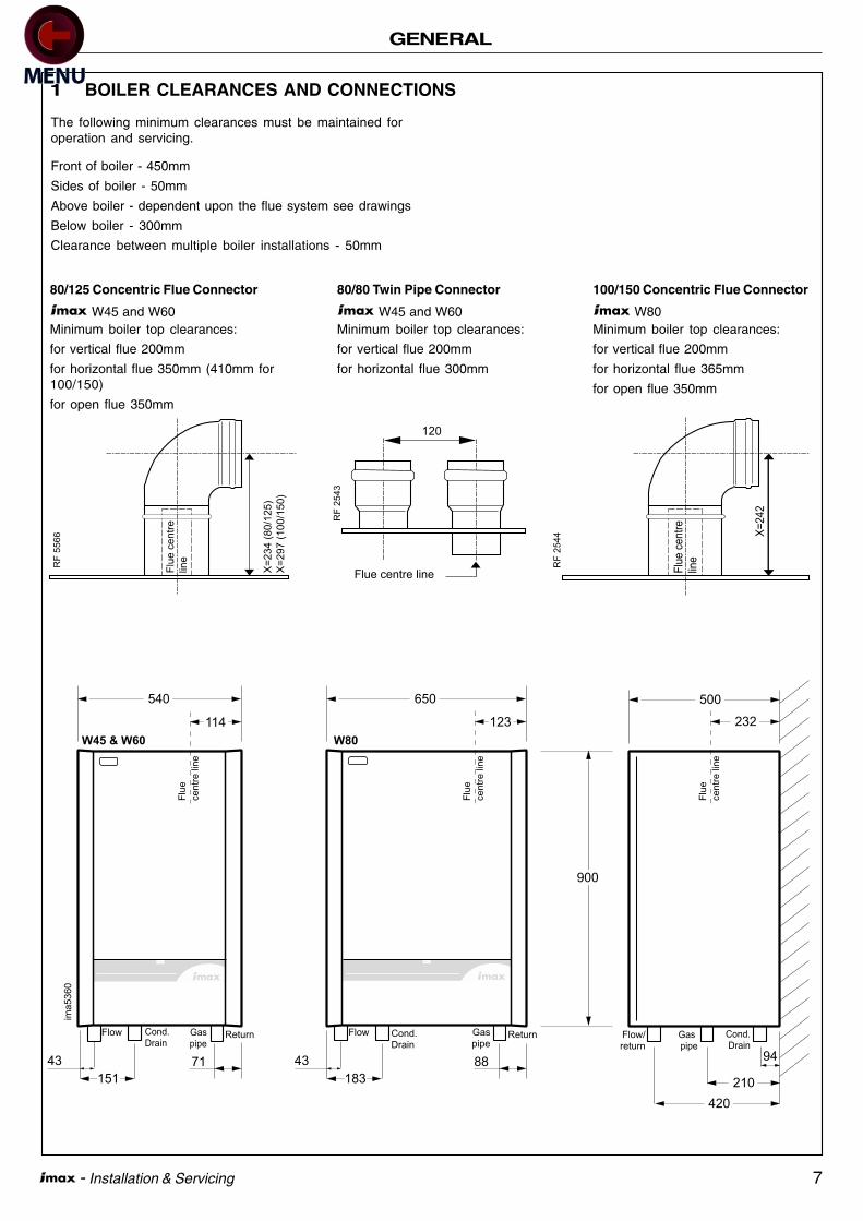
1 BOILER CLEARANCES AND CONNECTIONS
The following minimum clearances must be maintained foroperation and servicing.
Front of boiler - 450mm
Sides of boiler - 50mm
Above boiler - dependent upon the flue system see drawings
Below boiler - 300mm
Clearance between multiple boiler installations - 50mm
PUSH
W80
PUSH
W45 & W60
ima
53
60
650
123
540 500
232
210
420
900
94
183
43 88
Flow Cond.Drain
Gaspipe
151
43 71
Flow Flow/return
Return ReturnCond.Drain
Cond.Drain
Gaspipe
Gas pipe
Flu
e
ce
ntr
e lin
e
114
Flu
e
ce
ntr
e lin
e
Flu
e
ce
ntr
e lin
e
80/125 Concentric Flue Connector
W45 and W60Minimum boiler top clearances:
for vertical flue 200mm
for horizontal flue 350mm (410mm for100/150)
for open flue 350mm
80/80 Twin Pipe Connector
W45 and W60Minimum boiler top clearances:
for vertical flue 200mm
for horizontal flue 300mm
100/150 Concentric Flue Connector
W80Minimum boiler top clearances:
for vertical flue 200mm
for horizontal flue 365mm
for open flue 350mm
Flu
e c
en
tre
line
RF
55
66
X=
23
4 (
80
/12
5)
X=
29
7 (
10
0/1
50
)
RF
25
43
Flue centre line
120
Flu
e c
en
tre
line
X=
24
2
RF
2544
8 - Installation & Servicing
GENERAL
Feed/expansion
cistern500mm
minimum
3000mm
minimum
System
flow to
pump
Inverted cold
feed entry
Cold
Feed
Water
level
(cold)
Open vent
System
return
Connections
to boiler
ima5351
30
00
min
imu
m
ima
53
52
Hose unions
Temporary hose
(disconnect after filling)
Additional
stop valve
Double check valve
assembly
(note direction of flow)
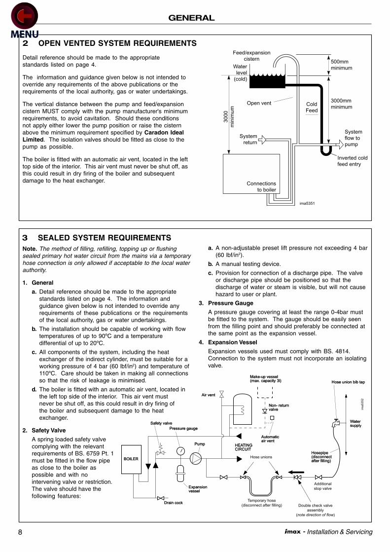
3 SEALED SYSTEM REQUIREMENTSNote. The method of filling, refilling, topping up or flushingsealed primary hot water circuit from the mains via a temporaryhose connection is only allowed if acceptable to the local waterauthority.
1. General
a. Detail reference should be made to the appropriatestandards listed on page 4. The information andguidance given below is not intended to override anyrequirements of these publications or the requirementsof the local authority, gas or water undertakings.
b. The installation should be capable of working with flowtemperatures of up to 90ºC and a temperaturedifferential of up to 20ºC.
c. All components of the system, including the heatexchanger of the indirect cylinder, must be suitable for aworking pressure of 4 bar (60 lbf/in2) and temperature of110ºC. Care should be taken in making all connectionsso that the risk of leakage is minimised.
d. The boiler is fitted with an automatic air vent, located inthe left top side of the interior. This air vent mustnever be shut off, as this could result in dry firing ofthe boiler and subsequent damage to the heatexchanger.
2. Safety Valve
A spring loaded safety valvecomplying with the relevantrequirements of BS. 6759 Pt. 1must be fitted in the flow pipeas close to the boiler aspossible and with nointervening valve or restriction.The valve should have thefollowing features:
a. A non-adjustable preset lift pressure not exceeding 4 bar(60 lbf/in2).
b. A manual testing device.
c. Provision for connection of a discharge pipe. The valveor discharge pipe should be positioned so that thedischarge of water or steam is visible, but will not causehazard to user or plant.
3. Pressure Gauge
A pressure gauge covering at least the range 0-4bar mustbe fitted to the system. The gauge should be easily seenfrom the filling point and should preferably be connected atthe same point as the expansion vessel.
4. Expansion Vessel
Expansion vessels used must comply with BS. 4814.Connection to the system must not incorporate an isolatingvalve.
2 OPEN VENTED SYSTEM REQUIREMENTS
Detail reference should be made to the appropriatestandards listed on page 4.
The information and guidance given below is not intended tooverride any requirements of the above publications or therequirements of the local authority, gas or water undertakings.
The vertical distance between the pump and feed/expansioncistern MUST comply with the pump manufacturer's minimumrequirements, to avoid cavitation. Should these conditionsnot apply either lower the pump position or raise the cisternabove the minimum requirement specified by Caradon IdealLimited. The isolation valves should be fitted as close to thepump as possible.
The boiler is fitted with an automatic air vent, located in the lefttop side of the interior. This air vent must never be shut off, asthis could result in dry firing of the boiler and subsequentdamage to the heat exchanger.
9 - Installation & Servicing
INSTALLATION
5
6
1
78
3110
2
1
12
4
3
20
23
24
15
16
21
18
17
19
2521
1113 14
9
9
22
W45/60
im 5564
10
12A
52
8
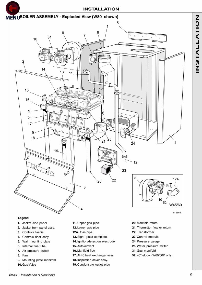
4 BOILER ASSEMBLY - Exploded View (W80 shown)
Legend
1. Jacket side panel
2. Jacket front panel assy.
3. Controls fascia
4. Controls door assy.
5. Wall mounting plate
6. Internal flue tube
7. Air pressure switch
8. Fan
9. Mounting plate manifold
10. Gas Valve
11. Upper gas pipe
12. Lower gas pipe
12A. Gas pipe
13. Sight glass complete
14. Ignition/detection electrode
15. Auto air vent
16. Manifold flow
17. AH-5 heat exchanger assy.
18. Inspection cover assy.
19. Condensate outlet pipe
20. Manifold return
21. Thermistor flow or return
22. Transformer
23. Control module
24. Pressure gauge
25. Water pressure switch
31. Gas manifold
52. 45º elbow (W60/60P only)
INS
TA
LL
AT
ION
10 - Installation & Servicing
INSTALLATION
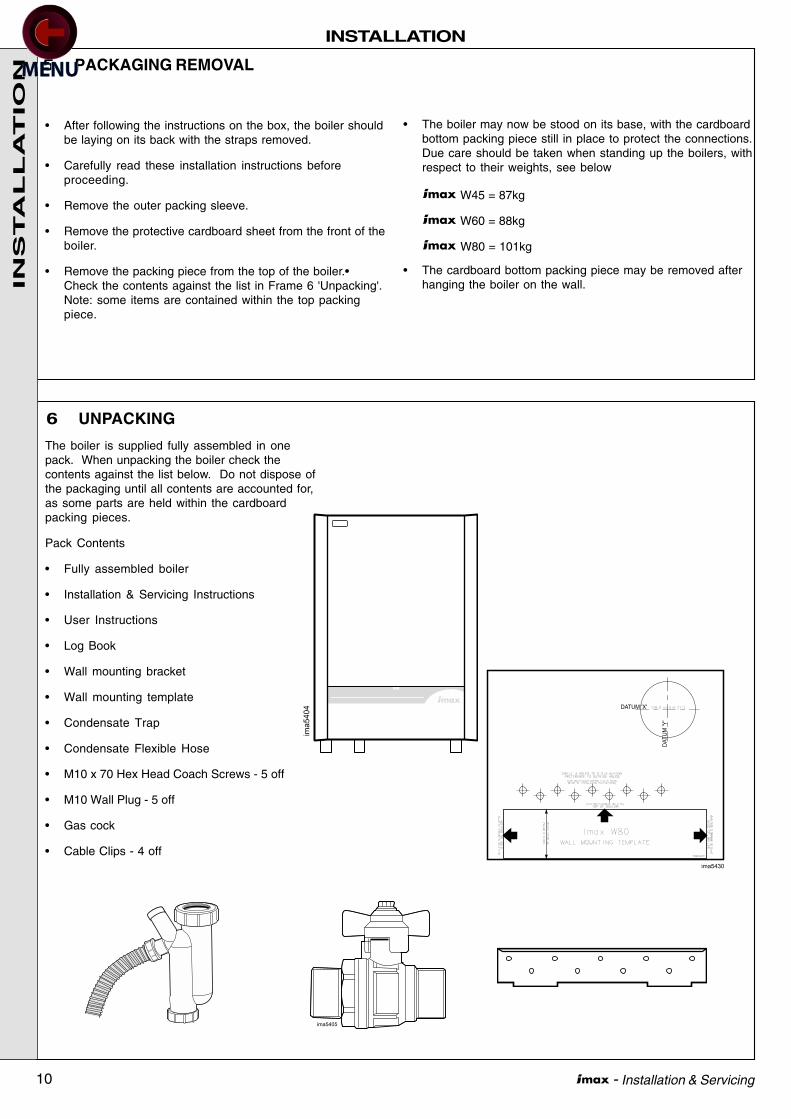
6 UNPACKING
5 PACKAGING REMOVAL
The boiler is supplied fully assembled in onepack. When unpacking the boiler check thecontents against the list below. Do not dispose ofthe packaging until all contents are accounted for,as some parts are held within the cardboardpacking pieces.
Pack Contents
• Fully assembled boiler
• Installation & Servicing Instructions
• User Instructions
• Log Book
• Wall mounting bracket
• Wall mounting template
• Condensate Trap
• Condensate Flexible Hose
• M10 x 70 Hex Head Coach Screws - 5 off
• M10 Wall Plug - 5 off
• Gas cock
• Cable Clips - 4 off
PUSH
ima5404
ima5405
• After following the instructions on the box, the boiler shouldbe laying on its back with the straps removed.
• Carefully read these installation instructions beforeproceeding.
• Remove the outer packing sleeve.
• Remove the protective cardboard sheet from the front of theboiler.
• Remove the packing piece from the top of the boiler.•Check the contents against the list in Frame 6 'Unpacking'.Note: some items are contained within the top packingpiece.
• The boiler may now be stood on its base, with the cardboardbottom packing piece still in place to protect the connections.Due care should be taken when standing up the boilers, withrespect to their weights, see below
W45 = 87kg
W60 = 88kg
W80 = 101kg
• The cardboard bottom packing piece may be removed afterhanging the boiler on the wall.
ima5430
DATUM 'X'
DA
TU
M 'Y
'
INS
TA
LL
AT
ION
11 - Installation & Servicing
INSTALLATION
8 PREPARING THE WALL
7 WALL MOUNTING TEMPLATE
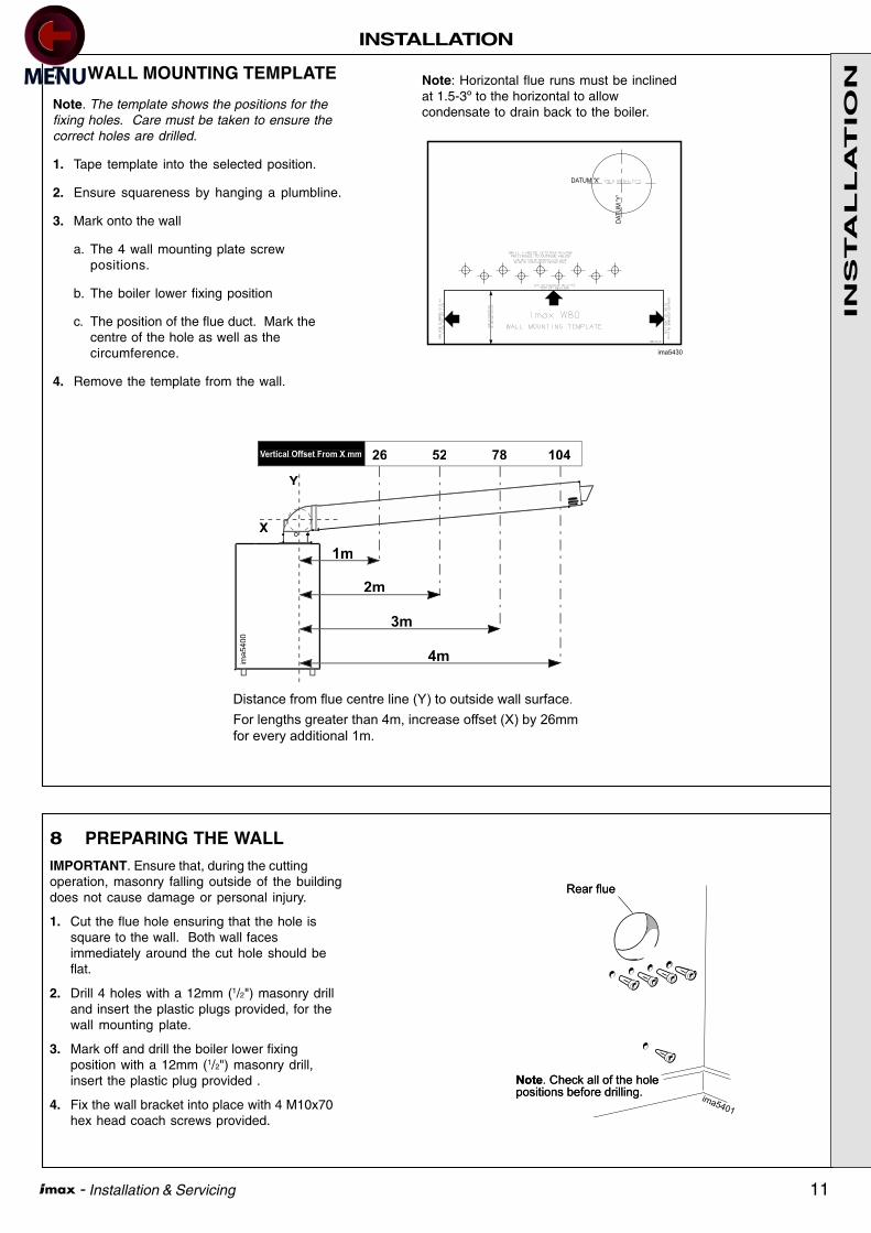
Note. The template shows the positions for thefixing holes. Care must be taken to ensure thecorrect holes are drilled.
1. Tape template into the selected position.
2. Ensure squareness by hanging a plumbline.
3. Mark onto the wall
a. The 4 wall mounting plate screwpositions.
b. The boiler lower fixing position
c. The position of the flue duct. Mark thecentre of the hole as well as thecircumference.
4. Remove the template from the wall.
IMPORTANT. Ensure that, during the cuttingoperation, masonry falling outside of the buildingdoes not cause damage or personal injury.
1. Cut the flue hole ensuring that the hole issquare to the wall. Both wall facesimmediately around the cut hole should beflat.
2. Drill 4 holes with a 12mm (1/2") masonry drilland insert the plastic plugs provided, for thewall mounting plate.
3. Mark off and drill the boiler lower fixingposition with a 12mm (1/2") masonry drill,insert the plastic plug provided .
4. Fix the wall bracket into place with 4 M10x70hex head coach screws provided.
ima5
400
X
Y
26 52 78 104Vertical Offset From X mm
Distance from flue centre line (Y) to outside wall surface.
For lengths greater than 4m, increase offset (X) by 26mm
for every additional 1m.
4m
3m
2m
1m
ima5430
DATUM 'X'
DA
TU
M 'Y
'
Note: Horizontal flue runs must be inclinedat 1.5-3º to the horizontal to allowcondensate to drain back to the boiler.
INS
TA
LL
AT
ION
12 - Installation & Servicing
INSTALLATION
10 VENTILATION
9 MOUNTING THE BOILER
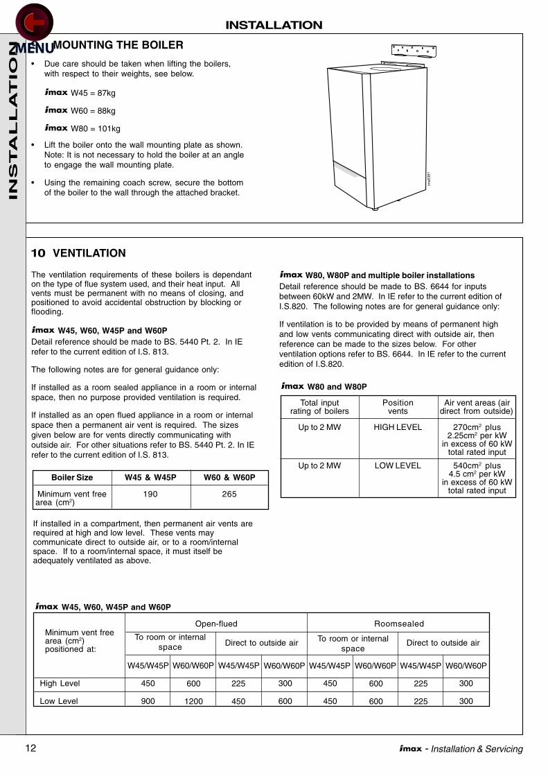
The ventilation requirements of these boilers is dependanton the type of flue system used, and their heat input. Allvents must be permanent with no means of closing, andpositioned to avoid accidental obstruction by blocking orflooding.
W45, W60, W45P and W60PDetail reference should be made to BS. 5440 Pt. 2. In IErefer to the current edition of I.S. 813.
The following notes are for general guidance only:
If installed as a room sealed appliance in a room or internalspace, then no purpose provided ventilation is required.
If installed as an open flued appliance in a room or internalspace then a permanent air vent is required. The sizesgiven below are for vents directly communicating withoutside air. For other situations refer to BS. 5440 Pt. 2. In IErefer to the current edition of I.S. 813.
ima5361
• Due care should be taken when lifting the boilers,with respect to their weights, see below.
W45 = 87kg
W60 = 88kg
W80 = 101kg
• Lift the boiler onto the wall mounting plate as shown.Note: It is not necessary to hold the boiler at an angleto engage the wall mounting plate.
• Using the remaining coach screw, secure the bottomof the boiler to the wall through the attached bracket.
Boiler Size W45 & W45P W60 & W60P
Minimum vent free 190 265area (cm2)
If installed in a compartment, then permanent air vents arerequired at high and low level. These vents maycommunicate direct to outside air, or to a room/internalspace. If to a room/internal space, it must itself beadequately ventilated as above.
W80, W80P and multiple boiler installationsDetail reference should be made to BS. 6644 for inputsbetween 60kW and 2MW. In IE refer to the current edition ofI.S.820. The following notes are for general guidance only:
If ventilation is to be provided by means of permanent highand low vents communicating direct with outside air, thenreference can be made to the sizes below. For otherventilation options refer to BS. 6644. In IE refer to the currentedition of I.S.820.
Total input Position Air vent areas (airrating of boilers vents direct from outside)
Up to 2 MW HIGH LEVEL 270cm2 plus2.25cm2 per kW
in excess of 60 kWtotal rated input
Up to 2 MW LOW LEVEL 540cm2 plus4.5 cm2 per kW
in excess of 60 kWtotal rated input
W80 and W80P
450
900
225
450
High Level
Low Level
W45/W45P
To room or internalspace
To room or internalspace
450
450
225
225
Open-flued RoomsealedMinimum vent freearea (cm2)positioned at:
W45, W60, W45P and W60P
Direct to outside air Direct to outside air
W60/W60P W45/W45P W60/W60P W45/W45P W60/W60P W45/W45P W60/W60P
300
300
600
1200
300
600
600
600
INS
TA
LL
AT
ION
13 - Installation & Servicing
INSTALLATION
RF 5755
RF 5756
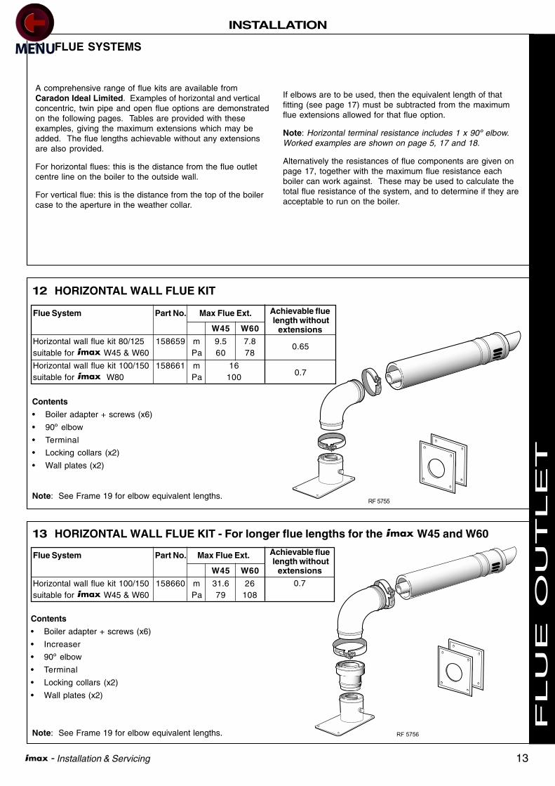
12 HORIZONTAL WALL FLUE KIT
Flue System Part No. Max Flue Ext.
W45 W60
Horizontal wall flue kit 80/125 158659 m 9.5 7.8suitable for W45 & W60 Pa 60 78
Horizontal wall flue kit 100/150 158661 m 16suitable for W80 Pa 100
Contents
• Boiler adapter + screws (x6)
• 90º elbow
• Terminal
• Locking collars (x2)
• Wall plates (x2)
13 HORIZONTAL WALL FLUE KIT - For longer flue lengths for the W45 and W60
Flue System Part No. Max Flue Ext.
W45 W60
Horizontal wall flue kit 100/150 158660 m 31.6 26suitable for W45 & W60 Pa 79 108
Contents
• Boiler adapter + screws (x6)
• Increaser
• 90º elbow
• Terminal
• Locking collars (x2)
• Wall plates (x2)
11 FLUE SYSTEMS
A comprehensive range of flue kits are available fromCaradon Ideal Limited. Examples of horizontal and verticalconcentric, twin pipe and open flue options are demonstratedon the following pages. Tables are provided with theseexamples, giving the maximum extensions which may beadded. The flue lengths achievable without any extensionsare also provided.
For horizontal flues: this is the distance from the flue outletcentre line on the boiler to the outside wall.
For vertical flue: this is the distance from the top of the boilercase to the aperture in the weather collar.
If elbows are to be used, then the equivalent length of thatfitting (see page 17) must be subtracted from the maximumflue extensions allowed for that flue option.
Note: Horizontal terminal resistance includes 1 x 90º elbow.Worked examples are shown on page 5, 17 and 18.
Alternatively the resistances of flue components are given onpage 17, together with the maximum flue resistance eachboiler can work against. These may be used to calculate thetotal flue resistance of the system, and to determine if they areacceptable to run on the boiler.
Achievable flue length without
extensions
0.65
0.7
Achievable flue length without
extensions
0.7
Note: See Frame 19 for elbow equivalent lengths.
Note: See Frame 19 for elbow equivalent lengths. F
LU
E O
UT
LE
T

14 - Installation & Servicing
INSTALLATION
14 VERTICAL ROOF FLUE KIT
Contents
• Boiler adapter + screws (x6)
• Terminal
• Locking Collar
• Finishing plates (x2)
• Bracket
RF2498
Note: See Frame 19 for elbow equivalent lengths.
15 VERTICAL ROOF FLUE KIT - For longer flue lengths for the W45 and W60
Contents
• Boiler adapter + screws (x6)
• Increaser
• Terminal
• Locking Collars (x2)
• Finishing plates (x2)
• Bracket
RF2499
Flue System Part No. Max Flue Ext.
W45 W60
Vertical roof kit 80/125 158654 m 9.5 7.8suitable for W45 & W60 Pa 60 78
Vertical roof kit 100/150 158656 m 16suitable for W80 Pa 100
Achievable flue length without
extensions
0.65
0.8
Note: See Frame 19 for elbow equivalent lengths.
Flue System Part No. Max Flue Ext.
W45 W60
Vertical roof kit 100/150 158655 m 31.6 26suitable for W45 & W60 Pa 79 108
Achievable flue length without
extensions
0.9
F
LU
E O
UT
LE
T

15 - Installation & Servicing
INSTALLATION
10
0
10
20
0 20 30
W45
W60
Flu
e Tu
be
Len
gth
(m
)
Air Tube Length (m)
ima5
452
16 OPEN FLUE KITS
Contents
158662 / 158663• Boiler adapter + screws (x6)• Air inlet grille
158769 / 158770• Terminal
Flue System Part No. Max Flue Ext.
W45 W60
Open flue kit 80/125 suitable 158662 + m 20 13.3for W45 & W60 158769 Pa 60 80
Open flue kit 100/150 158663 + m 29suitable for W80 158770 Pa 100
17 TWIN PIPE FLUES W45 and W60
Twin pipe flue systems can be created using these kits. The air is drawn in from ahorizontal wall terminal and the flue exhausted through either a vertical roof orhorizontal wall terminal.
The maximum flue extension depends on the ratio of air to flue tube. By fixingeither the air or flue tube length, you can determine how much of the other can befitted using the appropriate line from the graph below. An example is marked onthe graph. The example assumes the air tube extension has been fixed at 4m.From the graph we can determine that the allowable flue tube extension lengthwould be 17.3m for W45 and 10.6m for W60.
Note: See Frame 19 for elbow equivalent lengths.RF2501
Wall plug - 8 off
Screw - 8 off
Wall plug - 8 off
Screw - 8 off
or
RF 2545
Kit
158769
Kit
158773
Kit 158777
Kit 158771
(pair)
Kit
158773
Kit
158686
Kit 158778
F
LU
E O
UT
LE
T

16 - Installation & Servicing
INSTALLATION
18 FLUE KIT ACCESSORIES
RF 5757
1 2
5
3
46
7
8
9 10
1.
2.
3.
4.
5.
6.
7.
8.
9.
10.
90º elbow (concentric)
45º elbow (concentric)
90º elbow
45º elbow (pair)
Flat Weather Collar
Pitched Weather Collar
1m Extension (concentric)
1m Extension (pair)
Twin pipe adapter 80/80
Increaser 80-100
152616
152618
n/a
n/a
152611
152609
152400
n/a
n/a
n/a
152617
152619
n/a
n/a
152612
152610
152401
n/a
n/a
n/a
Accessory80/125 100/150
Part No.
n/a
n/a
158773
158775
158780
158779
n/a
158771
158686
152404
80
n/a
n/a
158774
158776
158780
158779
n/a
158772
n/a
n/a
100
F
LU
E O
UT
LE
T
17 - Installation & Servicing
INSTALLATION
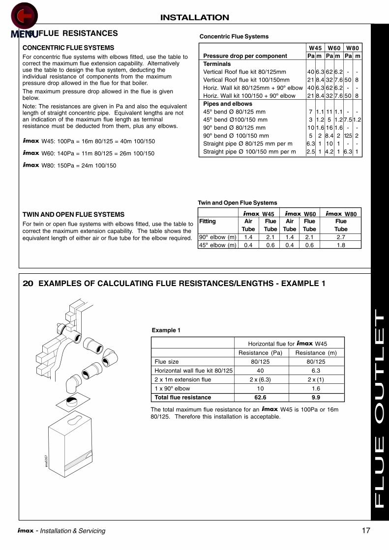
19 FLUE RESISTANCES
CONCENTRIC FLUE SYSTEMSFor concentric flue systems with elbows fitted, use the table tocorrect the maximum flue extension capability. Alternativelyuse the table to design the flue system, deducting theindividual resistance of components from the maximumpressure drop allowed in the flue for that boiler.The maximum pressure drop allowed in the flue is givenbelow.Note: The resistances are given in Pa and also the equivalentlength of straight concentric pipe. Equivalent lengths are notan indication of the maximum flue length as terminalresistance must be deducted from them, plus any elbows.
W45: 100Pa = 16m 80/125 = 40m 100/150
W60: 140Pa = 11m 80/125 = 26m 100/150
W80: 150Pa = 24m 100/150
TWIN AND OPEN FLUE SYSTEMSFor twin or open flue systems with elbows fitted, use the table tocorrect the maximum extension capability. The table shows theequivalent length of either air or flue tube for the elbow required.
Concentric Flue Systems
Pressure drop per component Pa m Pa m Pa mTerminalsVertical Roof flue kit 80/125mm 40 6.3 62 6.2 - -Vertical Roof flue kit 100/150mm 21 8.4 32 7.6 50 8Horiz. Wall kit 80/125mm + 90º elbow 40 6.3 62 6.2 - -Horiz. Wall kit 100/150 + 90º elbow 21 8.4 32 7.6 50 8Pipes and elbows45º bend Ø 80/125 mm 7 1.1 11 1.1 - -45º bend Ø100/150 mm 3 1.2 5 1.2 7.51.290º bend Ø 80/125 mm 10 1.6 16 1.6 - -90º bend Ø 100/150 mm 5 2 8.4 2 12.5 2Straight pipe Ø 80/125 mm per m 6.3 1 10 1 - -Straight pipe Ø 100/150 mm per m 2.5 1 4.2 1 6.3 1
W45 W60 W80
W45 W60 W80Fitting Air Flue Air Flue Flue
Tube Tube Tube Tube Tube90º elbow (m) 1.4 2.1 1.4 2.1 2.745º elbow (m) 0.4 0.6 0.4 0.6 1.8
Twin and Open Flue Systems
20 EXAMPLES OF CALCULATING FLUE RESISTANCES/LENGTHS - EXAMPLE 1
ima5357
Horizontal flue for W45
Resistance (Pa) Resistance (m)
Flue size 80/125 80/125
Horizontal wall flue kit 80/125 40 6.3
2 x 1m extension flue 2 x (6.3) 2 x (1)
1 x 90º elbow 10 1.6
Total flue resistance 62.6 9.9
The total maximum flue resistance for an W45 is 100Pa or 16m80/125. Therefore this installation is acceptable.
Example 1
F
LU
E O
UT
LE
T

18 - Installation & Servicing
INSTALLATION
ima5359
ima5358
21 EXAMPLES OF CALCULATING FLUE RESISTANCES/LENGTHS - EXAMPLE 2
Vertical Roof flue for W60
Resistance (Pa) Resistance (m)
Flue size 80/125 80/125
Vertical flue kit 80/125 62 6.2
2 x 1m extension flue 2 x (10) 2 x (1)
2 x 45º elbow 2 x (11) 2 x (1.1)
Total flue resistance 104 10.4
The total maximum flue resistance for an W60 is 140Pa or 11m80/125. Therefore this installation is acceptable.
Example 2
22 EXAMPLES OF CALCULATING FLUE RESISTANCES/LENGTHS - EXAMPLE 3
Horizontal flue for W80
Resistance (m)
Flue size 100
5 x 1m extension 5 x (1)
2 x 45º elbow 2 x (1.8)
Total flue resistance 8.6
The maximum flue extension for an W80 on open flue is 29m.Therefore this installation is acceptable.
Example 3
F
LU
E O
UT
LE
T

19 - Installation & Servicing
INSTALLATION
23 ASSEMBLING THE FLUE
Flue terminals or extension ducts may be cut to shorterlengths if required. When cutting a duct ensure it is square bymarking the length all the way around and only cut back theplain end. When cutting concentric duct it is important that theinner duct is maintained at 20mm longer than the outer duct toallow correct connection of the ducts. Care should be taken tosupport the inner duct when cutting the flue.
Note. Horizontal flue runs must be angled down between 1.5º -3º towards the boiler to allow the condensate to drain. For thisreason it is recommended that a support bracket is used forevery 1m of extension pipe.
Care must be taken when assembling flues, not to damage theseals.
See below for flue assembly examples.
Horizontalconcentricterminal
RF 2546
Wall platepainted
Wall plateunpainted
RF2548
Vertical
terminal
Weather collar
flat (shown)
or pitched
F
LU
E O
UT
LE
T
20 - Installation & Servicing
INSTALLATION
ima5355
boundary
boundary
JH
L
F
I
G
I
A
B
C
D, E
F
F
K
M
N
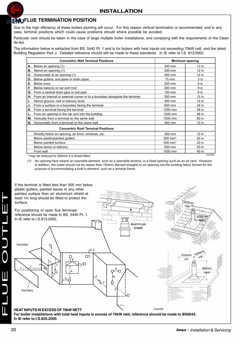
24 FLUE TERMINATION POSITIONDue to the high efficiency of these boilers pluming will occur. For this reason vertical termination is recommended, and in anycase, terminal positions which could cause problems should where possible be avoided.
Particular care should be taken in the case of large multiple boiler installations, and complying with the requirements of the CleanAir Act.
The information below is extracted from BS. 5440 Pt. 1 and is for boilers with heat inputs not exceeding 70kW nett, and the latestBuilding Regulation Part J. Detailed reference should still be made to these standards. In IE refer to I.S. 813:2002.
If the terminal is fitted less than 500 mm belowplastic gutters, painted eaves or any otherpainted surface then an aluminium shield atleast 1m long should be fitted to protect thesurface.
For positioning of open flue terminalsreference should be made to BS. 5440 Pt. 1.In IE refer to I.S.813.2002.
Concentric Wall Terminal Positions
Below an opening (1)
Above an opening (1)
Horizontally to an opening (1)
Below gutters, soil pipes or drain pipes
Below eves
Below balcony or car port roof
From a vertical drain pipe or soil pipe
From an internal or external corner or to a boundary alongside the terminal
Above ground, roof or balcony level
From a surface or a boundary facing the terminal
From a terminal facing the terminal
From an opening in the car port into the building
Vertically from a terminal on the same wall
Horizontally from a terminal on the same wall
300 mm
300 mm
300 mm
75 mm
200 mm
200 mm
150 mm
300 mm
300 mm
600 mm
1200 mm
1200 mm
1500 mm
300 mm
12 in
12 in
12 in
3 in
8 in
8 in
6 in
12 in
12 in
24 in
48 in
48 in
60 in
12 in
300 mm
500 mm*
500 mm*
500 mm
1000 mm
12 in
20 in
20 in
20 in
40 in
A.
B.
C.
D.
E.
F.
G.
H.
I.
J.
K.
L.
M.
N.
Minimum spacing
Concentric Roof Terminal Positions
Directly below an opening, air brick, windows, etc.
Below plastic/painted gutters
Below painted surface
Below eaves or balcony
From wall
* may be reduced to 300mm if a shield fitted
(1) An opening here means an openable element, such as a openable window, or a fixed opening such as an air vent. However,
in addition, the outlet should not be nearer than 150mm (fanned draught) to an opening into the building fabric formed for the
purpose of accommodating a built in element, such as a window frame.
ima5263
HEAT INPUTS IN EXCESS OF 70kW NETTFor boiler installations with total heat inputs in excess of 70kW nett, reference should be made to BS6644.In IE refer to I.S.820.2000.
FLU
E O
UT
LE
T

21 - Installation & Servicing
INSTALLATION
PUSHPUSH PUSH
3332
32 1
332 1
9 9 91
64
6
10
6
7
5
ima5461
8
88
25 BOILER FRAME AND HEADER KITS
Individual boiler frame kits are available,providing the option of mounting theboilers away from the boiler house wall.These frames can be bolted together formultiple installations.
A selection of 2 and 3 boiler water andgas header kits are available. These aresuitable for a combination of differentboilers.
26 SEQUENCER CONTROL OF MULTIPLE BOILERS
In installations where the heat load isgreater than the boiler capacity anideal solution is to use multipleboiler arrangements.
The ideal way to control a multipleboiler installation is with ourmodulating sequencer
See below a typical installation withour modulating sequencer kit. Thisdevice is capable of controlling up to5 boilers.
Legend
1. Non-return valve
2. Safety valve
3. Service valve
4. Mixing header
5. System pump
6. Modulating Sequencer kitcomplete with outdoorsensor and flow sensor
7. Flue gas terminal
8. Drain cock
9. Shunt pump
10. Room Sensor
LEGEND
1. Frame kit
2. 3 Blr. flow & return header kit
3. 3 Blr. gas header kit
4. Connection kit (includes essentialconnection and valve components)
5. Mixing header
6. Pump Kit (supplied separately if required)
1
4
5
3
6
2
ima5
462
INS
TA
LL
AT
ION

22 - Installation & Servicing
INSTALLATION
The condensate trap provided within the hardware pack mustbe connected to the condensate drain on the bottom of theboiler and then connected to a drainage point, preferablywithin the building.
The pipe size from the condensate trap is 25mm.
The routing of the drain must be made to allow a minimum fallof 1 in 20 away from the boiler, throughout its length.
IMPORTANT. Any external runs must be kept to a minimumand insulated. This is to avoid freezing in cold weathercausing blocking.
All pipework and fittings in the condensate drain system mustbe made of plastic. No other materials may be used.
Ensure condensate trap is full of water before lighting.
27 CONDENSATE DRAIN
im 2
5003
28 BOILER WATER CONNECTIONS
The boiler flow and return pipes areterminated with a 1 1/4" BSP male taperconnection located at the bottom of theappliance.
Note. This appliance is NOT suitable for usewith a direct hot water cylinder.
Plastic plugs fitted into the open ends of theflow and return pipes must be removedbefore connecting the system pipework.
PUSH
ima5356
Flow Return
29 FROST PROTECTION
The boiler has built into its control system the facility toprotect the boiler only against freezing.
If the boiler flow temperature T1, falls below 7ºC the pump runswithout the boiler firing until the temperature exceeds 10ºC.
If the flow temperature falls below 3ºC the boiler will fire atminimum rate until the temperature exceeds 10ºC.
Central heating systems fitted wholly inside the buildingdo not normally require frost protections as the buildingacts as a 'storage heater' and can normally be left at least24 hours without frost damage. However, if parts of thepipework run outside the building or if the boiler will be leftoff for more than a day or so, then a frost thermostatshould be wired into the system, see Frame 48.
INS
TA
LL
AT
ION

23 - Installation & Servicing
INSTALLATION
Warning. This appliance MUST be efficiently earthed.
A mains supply of 230V 50Hz is required. The supply wiringMUST be suitable for mains voltage. Wiring should be 3 corePVC insulated cable NOT LESS than 0.75mm2 (24 x 0.2 mm)and to BS. 6500, Table 16. The fuse rating should be 3A.
Wiring external to the boiler MUST be in accordance with thecurrent I.E.E. (BS7671) Wiring Regulations and any localregulations. For Ireland reference should be made to thecurrent ETCI rules for electrical installations.
Connection should be made in a way that allows completeisolation of the electrical supply - such as a double pole switch,
31 ELECTRICAL CONNECTIONS
having a 3mm (1/8") contact separation in both poles, or aplug and unswitched socket serving only the boiler andsystem controls. The means of isolation must be accessibleto the user after installation.
When making mains electrical connections to the boiler it isimportant that the wires are prepared in such a way that theearth conductor is longer than the current carryingconductors, such that if the cord anchorage should slip thecurrent carrying conductors become taut before the earthingconductor.
4 self adhesive cable clips are provided to aid routing of thewiring across the bottom panel of the boiler.
30 GAS CONNECTION
Refer to Frame 1 for details of the position of the gasconnection.
A MINIMUM working gas pressure of 17.5 mbar (7" w.g.) must beavailable at the boiler inlet for natural gas and 37mbar forpropane with the boiler firing. Refer to 'Servicing' for details ofthe pressure test point position.
Extend a gas supply pipe NOT LESS THAN 22mm O.D. to theboiler and connect using the gas cock provided.
Note. If the pipe run from the meter to the boiler is greater than3m (10') it is recommended that a 28 mm O.D. pipe is used.
IMPORTANT. The gas service cock contains a non-metallic sealso must not be overheated when making capillary connections.
External wiring MUST be in accordance with the current I.E.E.(BS7671) Wiring Regulations. For Ireland reference should bemade to the current ETCI rules for electrical installations.
The wiring diagrams illustrated in Frames 48, 49 and 50 coverthe systems most likely to be used with this appliance.
For wiring external controls to the boiler, reference should bemade to the systems wiring diagram supplied by the relevantmanufacturer in conjunction with the connection diagramshown in Frame 33.
Difficulty in wiring should not arise, providing the followingdirections are observed:
1. The appliance must be wired with a permanent live supply.External controls should NOT be wired in series with thismains input. Controlling the mains input in this way willprevent the pump over-run sequence and may causedamage to the heat exchanger.
2. 230V AC output is provided and must be used for thesystem pump and optionally for a DHW pump or valve,programmer and thermostats. Care must be taken toensure that the earth conductor is longer than the currentcarrying conductors for reasons given in Frame 31.
32 EXTERNAL WIRING
3. Input terminals are available for connecting a variety ofsystem controls for heating demand, and optionally for DHWdemand.
Heating demand can be controlled by:
• 230V programmer and/or room thermostat
• programmable room thermostat kit
• Modulating sequencer kit
• a bms (connected via optional board)
• outside temperature sensor
DHW demand can be controlled by:
• 230V programmer and/or cylinder thermostat
• tank sensor kit (this cannot be timer controlled exceptwhen using our programmable room thermostat, whichcan block DHW demand during the 'night' period).
The electrical supply and their inputs onto the boiler can beseen in Frame 33.
4. An optional outside temperature sensor may be fitted foroutside weather compensation. See Frame 33 forconnection details.
INS
TA
LL
AT
ION
24 - Installation & Servicing
INSTALLATION
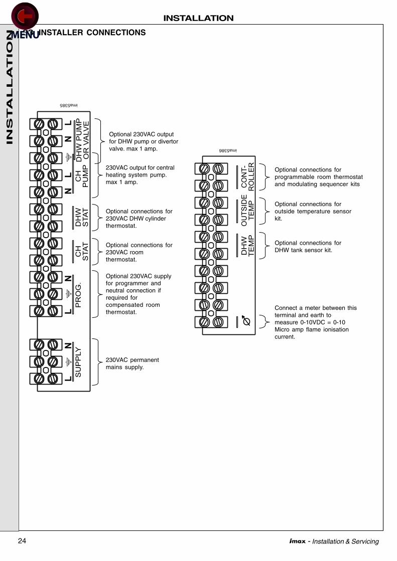
33 INSTALLER CONNECTIONS
DHW
TEMP
OUTSIDE
TEMP
CONT-
ROLLER
ima5386
Connect a meter between thisterminal and earth tomeasure 0-10VDC = 0-10Micro amp flame ionisationcurrent.
Optional connections forDHW tank sensor kit.
Optional connections foroutside temperature sensorkit.
Optional connections forprogrammable room thermostatand modulating sequencer kits
L
SUPPLY
NL
PROG.
DHW
STAT
CH
PUMPDHWPUMP
ORVALVE
CH
STAT
NL
NL
N
ima5385
230VAC permanentmains supply.
Optional 230VAC supplyfor programmer andneutral connection ifrequired forcompensated roomthermostat.
Optional connections for230VAC roomthermostat.
Optional connections for230VAC DHW cylinderthermostat.
230VAC output for centralheating system pump.max 1 amp.
Optional 230VAC outputfor DHW pump or divertorvalve. max 1 amp.
INS
TA
LL
AT
ION

25 - Installation & Servicing
INSTALLATION
34 INTERNAL WIRING
ima5
565
br
g/y
b
br
g/y
b
bk
wsuppressor
suppressorbk
R 1
R 2
12
31
23
45
67
89
1011
12
LN
LN
NL
ND
HW
PU
MP
OR
VA
LVE
CH
PU
MP
DH
W S
TAT
CH
STA
T
PR
OG
SU
PP
LY
b bk br r y wCO
LO
UR
CO
DE
NT
C1
NT
C2
PW
R1
R2
RY
1R
Y2
RP
GV
BS
Flo
w th
erm
isto
rR
etur
n th
erm
isto
rW
ater
pre
ssur
e sw
itch
Rel
ay 1
230
VA
C c
oil
Rel
ay 2
230
VA
C c
oil
Rel
ay 1
Sw
itch
(sig
nal)
Rel
ay 2
Sw
itch
(sig
nal)
Rec
tifyi
ng p
lug
Gas
val
veB
urne
r sw
itch
- - - - - - - - - -
KE
Y
- - - - - -
Blu
eB
lack
Bro
wn
Red
Yello
wW
hite
g or v pk g/y
- - - - -
Gre
yO
rang
eV
iole
tP
ink
Gre
en/Y
ello
w
L
DIS
PLA
YB
OA
RD
b
bk
g/y
g
or
or
or
RY
1
wv
or
y
wr
r
r
r
b
p
bk
w/bk
b
g
v
RY
2
12
34
56
78
910
CO
NTR
OLL
ERO
UTS
IDE
TEM
PD
HW
TEM
P
g BP
PN
pN
l6
g/y
HA
X7
orX
8
bp
bk
r
g gBS
rb
br
b
g/y
PW
APS
NTC2
NTC1r
b
w
g
wp
r
bk
gor
w/bk
y
v
v
br
b
IGN
ITIO
N&
DE
TE
CT
ION
PR
OB
E
54
32
1
bk
b
b
br
x1
x51
2
3 4
x41
2
3 4
x31
2
3 4
5
6x2
w
TR
AN
SF
OR
ME
R
24VAC
230VAC
r
br
b
1 2
3
4
FAN
LN
TAC
HP
WM
FAN
PW
R60
& 8
0KW
ON
LY
RP
GV
1R
PG
V2
80kW
ON
LY
5 6N
L7
65
43
21
X10
78
9
CO
NT
RO
LM
OD
ULE
1011
12
80kW
ON
LY
MC
BA
1456
D
24 VA
C24 VA
C
INS
TA
LL
AT
ION
26 - Installation & Servicing
INSTALLATION
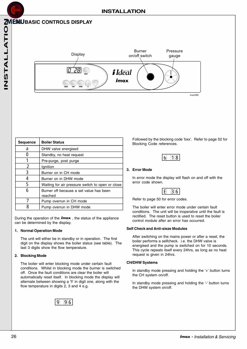
35 BASIC CONTROLS DISPLAY
During the operation of the , the status of the appliancecan be determined by the display.
1. Normal Operation Mode
The unit will either be in standby or in operation. The firstdigit on the display shows the boiler status (see table). Thelast 3 digits show the flow temperature.
2. Blocking Mode
The boiler will enter blocking mode under certain faultconditions. Whilst in blocking mode the burner is switchedoff. Once the fault conditions are clear the boiler willautomatically reset itself. In blocking mode the display willalternate between showing a '9' in digit one, along with theflow temperature in digits 2, 3 and 4 e.g.
9 9 6
6 1 8
Followed by the blocking code 'bxx'. Refer to page 52 forBlocking Code references.
3. Error Mode
In error mode the display will flash on and off with theerror code shown.
Refer to page 50 for error codes.
The boiler will enter error mode under certain faultconditions. The unit will be inoperative until the fault isrectified. The reset button is used to reset the boilercontrol module after an error has occurred.
Self Check and Anti-sieze Modules
After switching on the mains power or after a reset, theboiler performs a selfcheck. i.e. the DHW valve isenergised and the pump is switched on for 10 seconds.This cycle repeats itself every 24hrs, as long as no heatrequest is given in 24hrs.
CH/DHW Systems
In standby mode pressing and holding the '+' button turnsthe CH system on/off.
In standby mode pressing and holding the '-' button turnsthe DHW system on/off.
E 3 6
Sequence Boiler Status
a DHW valve energised
0 Standby, no heat request
1 Pre-purge, post purge
2 Ignition
3 Burner on in CH mode
4 Burner on in DHW mode
5 Waiting for air pressure switch to open or close
6 Burner off because a set value has beenreached
7 Pump overrun in CH mode
8 Pump overrun in DHW mode
INS
TA
LL
AT
ION
27 - Installation & Servicing
INSTALLATION
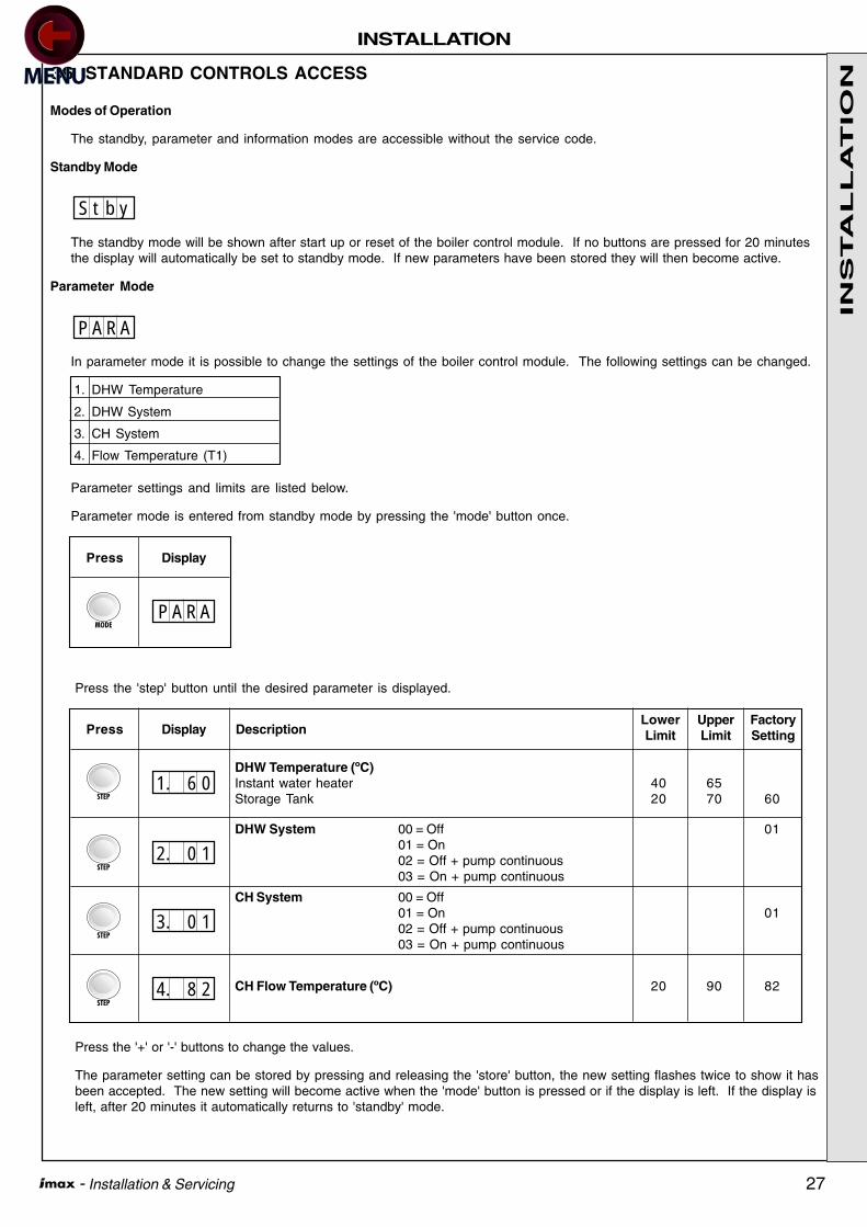
36 STANDARD CONTROLS ACCESS
Modes of Operation
The standby, parameter and information modes are accessible without the service code.
Standby Mode
The standby mode will be shown after start up or reset of the boiler control module. If no buttons are pressed for 20 minutesthe display will automatically be set to standby mode. If new parameters have been stored they will then become active.
Parameter Mode
In parameter mode it is possible to change the settings of the boiler control module. The following settings can be changed.
1. DHW Temperature
2. DHW System
3. CH System
4. Flow Temperature (T1)
Parameter settings and limits are listed below.
Parameter mode is entered from standby mode by pressing the 'mode' button once.
S t b y
P A R A
Press the 'step' button until the desired parameter is displayed.
Press the '+' or '-' buttons to change the values.
The parameter setting can be stored by pressing and releasing the 'store' button, the new setting flashes twice to show it hasbeen accepted. The new setting will become active when the 'mode' button is pressed or if the display is left. If the display isleft, after 20 minutes it automatically returns to 'standby' mode.
P A R A
Press Display
DHW Temperature (ºC)Instant water heater 40 65Storage Tank 20 70 60
Press DisplayFactorySetting
UpperLimit
LowerLimitDescription
DHW System 00 = Off 0101 = On02 = Off + pump continuous03 = On + pump continuous
1. 6 0
2. 0 1
CH System 00 = Off01 = On 0102 = Off + pump continuous03 = On + pump continuous
3. 0 1
CH Flow Temperature (ºC) 20 90 824. 8 2
INS
TA
LL
AT
ION
28 - Installation & Servicing
INSTALLATION
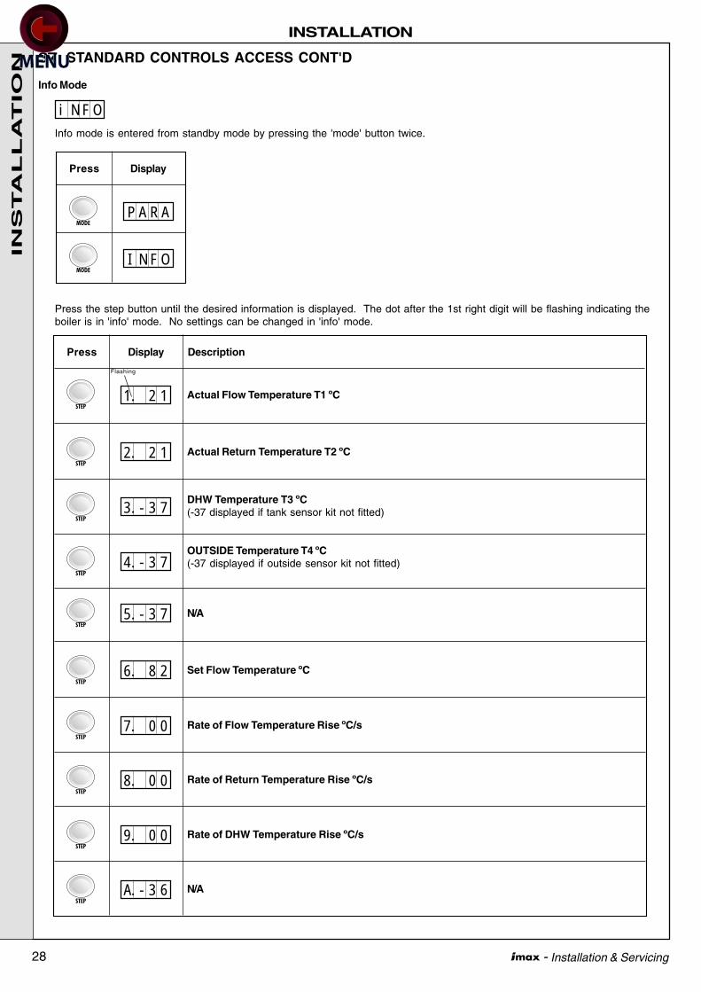
Info Mode
Info mode is entered from standby mode by pressing the 'mode' button twice.
Press the step button until the desired information is displayed. The dot after the 1st right digit will be flashing indicating theboiler is in 'info' mode. No settings can be changed in 'info' mode.
37 STANDARD CONTROLS ACCESS CONT'D
i N F O
P A R A
Press Display
I N F O
Actual Flow Temperature T1 ºC
Press Display Description
Actual Return Temperature T2 ºC
1. 2 1
2. 2 1
3. - 3 7
OUTSIDE Temperature T4 ºC(-37 displayed if outside sensor kit not fitted)4. - 3 7
DHW Temperature T3 ºC(-37 displayed if tank sensor kit not fitted)
N/A
Set Flow Temperature ºC
5. - 3 7
6. 8 2
7. 0 0
Rate of Return Temperature Rise ºC/s8. 0 0
Rate of Flow Temperature Rise ºC/s
9. 0 0
N/AA. - 3 6
Rate of DHW Temperature Rise ºC/s
Flashing
INS
TA
LL
AT
ION
29 - Installation & Servicing
INSTALLATION
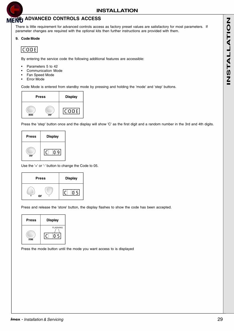
38 ADVANCED CONTROLS ACCESS
C O D E
C O D E
Press Display
C 0 9
Press Display
C 0 5
Press Display
or
C 0 5
Press Display
FLASHING
There is little requirement for advanced controls access as factory preset values are satisfactory for most parameters. Ifparameter changes are required with the optional kits then further instructions are provided with them.
9. Code Mode
By entering the service code the following additional features are accessible:
• Parameters 5 to 42• Communication Mode• Fan Speed Mode• Error Mode
Code Mode is entered from standby mode by pressing and holding the 'mode' and 'step' buttons.
Press the 'step' button once and the display will show 'C' as the first digit and a random number in the 3rd and 4th digits.
Use the '+' or '-' button to change the Code to 05.
Press and release the 'store' button, the display flashes to show the code has been accepted.
Press the mode button until the mode you want access to is displayed
INS
TA
LL
AT
ION

30 - Installation & Servicing
INSTALLATION
39 ADVANCED CONTROLS ACCESS CONT'D
Press Display FactorySetting
UpperLimit
LowerLimit
Description
DHW Temperature (ºC)Instant water heater 40 65Storage tank 20 70 60
P A R A
1. 6 0
2. 0 1
CH System 00 = Off 0101 = On02 = Off + pump continuous03 = On + pump continuous
3. 0 1
DHW System 00 = Off 0101 = On02 = Off + pump continuous03 = On + pump continuous
CH flow temperature (ºC) 20 90 82
Lowest CH flow temperature (ºC)When using outside temperature sensor compensation 15 60 20
4. 8 2
. 2 0
. - 0 5
Highest outside temperature (ºC)Than can influence temperature compensation 15 25 20 . 2 0
Lowest outside temperature (ºC)That can influence temperature compensation -20 10 -5
. - 0 2
Outside temperature correction (ºC)For boiler reading of outside temperature -01 05 00 . 0 0
Outside temperature (ºC)At which frost protection starts -30 10 -02
1
2
3
4
5
6
7
8
9
P05 appearsfor 1 second
P06
P07
P08
P09
Minimum CH flow temperature (ºC)Which will enable a CH request to be satisfied, when using 01 60 25outside temperature compensation.note 00 = Off
. 2 510
P10
Booster time (minutes) 01 30 00note 00 = Off . 0 011
P11
CH flow parallel shift 00 80 10For use with outside temperature sensor
. 1 012
P12
Maximum fan speed CH (hundreds) W45 55W60 55W80 Do not Do not 59
W45P adjust adjust 50W60P 49W80P 57
. 5 913
P13
INS
TA
LL
AT
ION
31 - Installation & Servicing
INSTALLATION
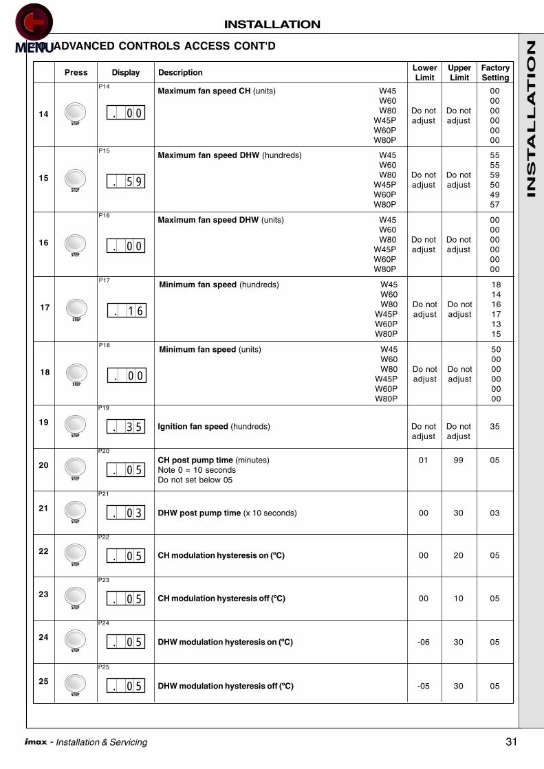
40 ADVANCED CONTROLS ACCESS CONT'D
Press Display FactorySetting
UpperLimit
LowerLimit
Description
. 0 0
. 5 9
14
15
Ignition fan speed (hundreds) Do not Do not 35adjust adjust
. 3 519
P19
CH post pump time (minutes) 01 99 05Note 0 = 10 secondsDo not set below 05
. 0 520
P20
DHW post pump time (x 10 seconds) 00 30 03 . 0 321
P21
P14Maximum fan speed CH (units) W45 00
W60 00W80 Do not Do not 00
W45P adjust adjust 00W60P 00W80P 00
P15Maximum fan speed DHW (hundreds) W45 55
W60 55W80 Do not Do not 59
W45P adjust adjust 50W60P 49W80P 57
. 0 016
P16Maximum fan speed DHW (units) W45 00
W60 00W80 Do not Do not 00
W45P adjust adjust 00W60P 00W80P 00
. 1 617
P17Minimum fan speed (hundreds) W45 18
W60 14W80 Do not Do not 16
W45P adjust adjust 17W60P 13W80P 15
. 0 018
P18Minimum fan speed (units) W45 50
W60 00W80 Do not Do not 00
W45P adjust adjust 00W60P 00W80P 00
CH modulation hysteresis on (ºC) 00 20 05 . 0 522
P22
CH modulation hysteresis off (ºC) 00 10 05 . 0 523
P23
DHW modulation hysteresis on (ºC) -06 30 05 . 0 524
P24
DHW modulation hysteresis off (ºC) -05 30 05 . 0 525
P25
INS
TA
LL
AT
ION
32 - Installation & Servicing
INSTALLATION
41 ADVANCED CONTROLS ACCESS CONT'D
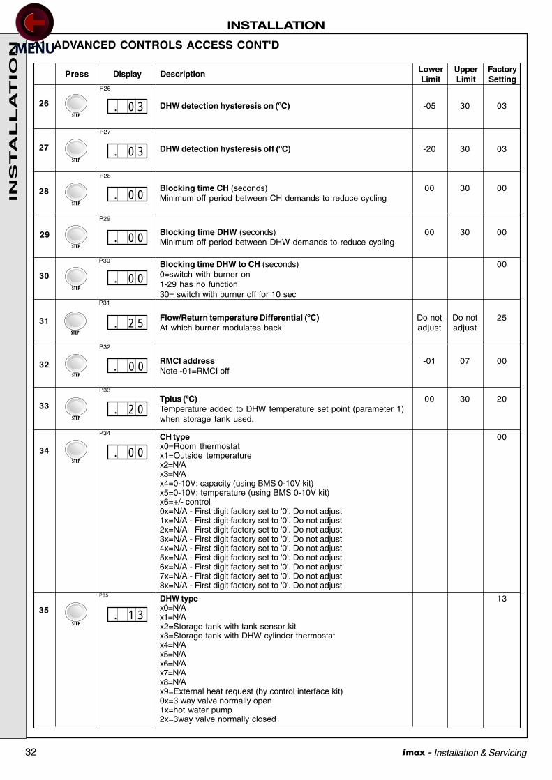
DHW type 13x0=N/Ax1=N/Ax2=Storage tank with tank sensor kitx3=Storage tank with DHW cylinder thermostatx4=N/Ax5=N/Ax6=N/Ax7=N/Ax8=N/Ax9=External heat request (by control interface kit)0x=3 way valve normally open1x=hot water pump2x=3way valve normally closed
Press Display FactorySetting
UpperLimit
LowerLimit
Description
. 0 3
. 0 3
. 0 0
. 0 0
Blocking time DHW to CH (seconds) 000=switch with burner on1-29 has no function30= switch with burner off for 10 sec
Flow/Return temperature Differential (ºC) Do not Do not 25At which burner modulates back adjust adjust
. 0 0
. 2 5
. 0 0
Tplus (ºC) 00 30 20Temperature added to DHW temperature set point (parameter 1)when storage tank used.
. 2 0
RMCI address -01 07 00Note -01=RMCI off
. 0 0CH type 00x0=Room thermostatx1=Outside temperaturex2=N/Ax3=N/Ax4=0-10V: capacity (using BMS 0-10V kit)x5=0-10V: temperature (using BMS 0-10V kit)x6=+/- control0x=N/A - First digit factory set to '0'. Do not adjust1x=N/A - First digit factory set to '0'. Do not adjust2x=N/A - First digit factory set to '0'. Do not adjust3x=N/A - First digit factory set to '0'. Do not adjust4x=N/A - First digit factory set to '0'. Do not adjust5x=N/A - First digit factory set to '0'. Do not adjust6x=N/A - First digit factory set to '0'. Do not adjust7x=N/A - First digit factory set to '0'. Do not adjust8x=N/A - First digit factory set to '0'. Do not adjust
26
27
28
29
30
31
32
33
34
P32
P33
P34
. 1 335
P35
P26
DHW detection hysteresis on (ºC) -05 30 03
DHW detection hysteresis off (ºC) -20 30 03
Blocking time CH (seconds) 00 30 00Minimum off period between CH demands to reduce cycling
Blocking time DHW (seconds) 00 30 00Minimum off period between DHW demands to reduce cycling
P27
P28
P29
P30
P31
INS
TA
LL
AT
ION

33 - Installation & Servicing
INSTALLATION
42 ADVANCED CONTROL ACCESS CONT'D
Press Display FactorySetting
UpperLimit
LowerLimit
Description
. - 0 1
. 4 1
. 0 0
. 3 5
N/A 10Value changes will not influence boiler
N/A 01Value changes will not influence boiler
. 1 0
. 0 1
. 0 0Low/Off cycle 00x0=offx1=onSpecial pump function CH/DHW0x=CH normal pump function, DHW normal pump function1x=CH pump off during heat request, DHW normal pump function2x=CH pump normal function, DHW pump 5 sec on delay afterheat request3x=CH pump off during heat request, DHW pump 5 sec on delayafter heat request
36
37
38
39
40
41
42
P42
P36Manual fanspeed (for service use) 00 100 -01Note -1=off00 = min fan speed50 = mid rate100 = max fan speed
N/A 41Value changes will not influence boiler
Flow temperature hold (ºC) 01 80 00Temperature maintained by boiler when no heat request.Note 0=Off
N/A 35Value changes will not influence boiler
P37
P38
P39
P40
P41
INS
TA
LL
AT
ION

34 - Installation & Servicing
INSTALLATION
43 INFORMATION MODE (with code)
44 COMMUNICATION MODE (with code)
Press Display Description
C O N NIn this mode the communication between the boiler control module, optional control interfacekit, and optional programmable room thermostat or modulating sequencer is shown.
No communication
There is only communication between the boiler control module and optional controls interfacekit.
There is communication between all devices.
FLASHING
FLASHING
I N F O
Actual Flow Temperature T1 ºC1. 2 1
FLASHING
Actual Return Temperature T2 ºC2. 2 1
3. - 3 7
Outside Temperature T4 ºC(-37 displayed if outside sensor kit not fitted)4. - 3 7
DHW Temperature T3 ºC(-37 displayed if tank sensor kit not fitted)
N/A5. - 3 7
Press Display Description
Set Flow Temperature ºC6. 8 2
7. 0 0
Rate of Return Temperature Rise ºC/s8. 0 0
Rate of Flow Temperature Rise ºC/s
9. 0 0
N/AA. - 3 6
Rate of DHW Temperature Rise ºC/s
INS
TA
LL
AT
ION
35 - Installation & Servicing
INSTALLATION
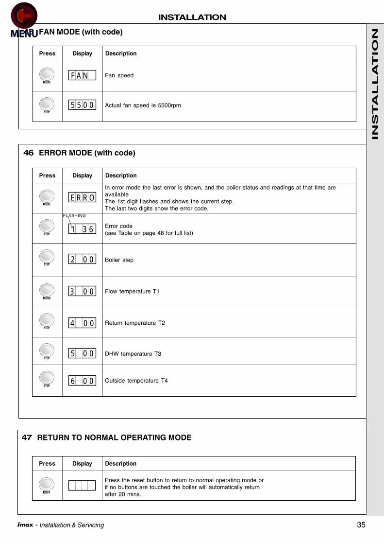
45 FAN MODE (with code)
46 ERROR MODE (with code)
Press Display Description
Fan speed
Actual fan speed ie 5500rpm
F A N
5 5 0 0
Press Display Description
In error mode the last error is shown, and the boiler status and readings at that time areavailableThe 1st digit flashes and shows the current step.The last two digits show the error code.
Error code(see Table on page 48 for full list)
E R R O
1 3 6
FLASHING
Boiler step2 0 0
Flow temperature T1
Return temperature T2
3 0 0
4 0 0
DHW temperature T35 0 0
Outside temperature T46 0 0
47 RETURN TO NORMAL OPERATING MODE
Press Display Description
Press the reset button to return to normal operating mode orif no buttons are touched the boiler will automatically returnafter 20 mins.
INS
TA
LL
AT
ION

36 - Installation & Servicing
INSTALLATION
48 INDEPENDENT SYSTEM CONTROLS
If the system controls are to be independent of the boiler, then the following method should be used for connecting the boiler.
No parameter modifications are required.
Frost Stat
if required
230vac
Permanent
main supply
Switched live from
external controls
generating call for heat
System pump
(maximum load
1 amp) connect via
a relay for greater
currents
49 MAINS VOLTAGE CH AND DHW CONTROLS WITH DHW PUMP OUTPUT
Pump
PumpNon return
valve
Non return
valve
Cylinder
thermostat
PUSH
Programmer Room stat
ima
54
54
ima5455
ROOM CYLINDER
No parameter modificationsare required.
Alternatives: Try ourprogrammable roomthermostat, outside sensor andtank sensor kit for enhanceduser comfort. Full instructionsprovided with kits.
Note.
If either pump requiresmore than 1 ampsupply current,connection must bemade via a relay
INS
TA
LL
AT
ION
37 - Installation & Servicing
INSTALLATION
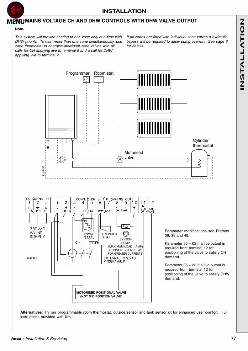
50 MAINS VOLTAGE CH AND DHW CONTROLS WITH DHW VALVE OUTPUT
Alternatives: Try our programmable room thermostat, outside sensor and tank sensor kit for enhanced user comfort. Fullinstructions provided with kits.
PUSH
Programmer Room stat
ima
54
56
Motorised
valve
Cylinder
thermostat
ima5455
MOTORISED POSITIONAL VALVE
(NOT MID POSITION VALVE)
SYSTEM
PUMP
(MAXIMUM LOAD 1 AMP)
CONNECT VIA A RELAY
FOR GREATER CURRENTS)
ROOM CYLINDER
sys
Parameter modifications see Frames38, 39 and 40.
Parameter 35 = 03 If a live output isrequired from terminal 12 forpositioning of the valve to satisfy CHdemand.
Parameter 35 = 23 If a live output isrequired from terminal 12 forpositioning of the valve to satisfy DHWdemand.
Note.
This system will provide heating to one zone only at a time withDHW priority. To heat more than one zone simultaneously, usezone thermostat to energise individual zone valves with allcalls for CH applying live to terminal 5 and a call for DHWapplying live to terminal 7.
If all zones are fitted with individual zone valves a hydraulicbypass will be required to allow pump overrun. See page 6for details.
INS
TA
LL
AT
ION

38 - Installation & Servicing
INSTALLATION
51 COMMISSIONING AND TESTING
A. ELECTRICAL INSTALLATION
1. Checks to ensure electrical safety should be carried outby a competent person.
2. ALWAYS carry out the preliminary electrical systemchecks, i.e. earth continuity, polarity, resistance to earthand short circuit, using a suitable meter.
WARNING. Whilst effecting the required gas soundness test and purging air from the gasinstallation, open all windows and doors, extinguish naked lights and DO NOT SMOKE.
52 INITIAL LIGHTING1. Check that the system has been filled and the boiler is not
air locked - air in the boiler could damage the heatexchanger. For this reason the airvent located in the left topside must never be shut off.
2. Check that all the drain cocks are closed and any valves inthe flow and return are open.
3. Check that the GAS SERVICE COCK IS ON.4. Fill the condensate trap with water before putting the unit
into operation (see Frame 66 for condensate trap removal).5. Check the indication on the pressure gauge. If the
pressure is less than 1 bar the installation should be filledup first (sealed system only).
6. Switch the electricity supply ON and check that all theexternal controls are calling for heat. Check burner switchis set to on.
7. The boiler will commence the ignition sequence. If after 5attempts the boiler has failed to light then it will lock out.Press the reset button to restart the ignition sequence.
Gas Rate8. Operate the boiler for 20 minutes and check the gas rate (Table
1). You should be able to read at least 90% of the nominal.
B. GAS INSTALLATION
1. The whole of the gas installation, including the meter,should be inspected and tested for soundness and thenpurged in accordance with the recommendations of therelevant standards listed on page 4.
In IE refer to I.S.813:2002.
9. To ensure the boiler operates at maximum rate withoutmodulating set the fan speed to maximum.
10. To set the fan speed to maximum. Press and hold in the'mode' and '+' buttons simultaneously. The display willshow as the first digit indicating the boiler isoperating at maximum rate.
11. To ensure the boiler operates at minimum rate withoutmodulating, set the fan speed to minimum
12. To set the fan speed to minimum. Press and hold in the'mode' and '-' buttons simultaneously. The display willshow as the first digit indicating the boiler isoperating at minimum rate.
13. Press the 'reset' button to return to normal operating mode.
Note.
It is possible to switch off the CH/DHW systems if the modeand +/- buttons are not held simultaneously. Refer to Frame 35under the heading CH/DHW Systems for guidance.
H
L
54 HANDING OVERROUTINE OPERATIONFull instructions covering routine lighting and operation of theboiler are given on the Lighting and Operation Instruction Labellocated on the inside of the lower controls door.
Draw the attention of the boiler owner or his representative to theLighting and Operating Instruction Label. Give a practicaldemonstration of the lighting and shutting down of the boiler.
Describe the function of the boiler and system controls and showhow they are adjusted and used.
Hand these Installation and Servicing Instructions, User'sInstructions and Log book to the customer and request him tokeep them in a safe place for ready reference. For IE, it is
necessary to complete a "Declaration of Conformity" to indicatecompliance to the appropriate standard.
IMPORTANT. Point out to the owner that the boiler must haveregular maintenance and cleaning, at least annually, in order toensure reliable and efficient operation. Regular attention willalso prolong the life of the boiler and should preferably beperformed at the end of the heating season.
After servicing, complete the service section of the log book andreturn to the owner or their representative.
Recommend that a contract for this work should be made withthe regional gas authority or a CORGI registered heatinginstaller. In IE servicing work must be carried out by acompetent person.
Make the following checks for correct operation.1. The correct operation of ANY secondary system controls
should be proved. Operate each control separately andcheck that the main burner or circulating pump, as the casemay be, responds.
2. Water circulation system;a. With the system HOT examine all water connections for
soundness.b. With the system still HOT, turn off the gas, water and
electricity supplies to the boiler and drain down to
complete the flushing process.c. Refill and vent the system, clear all air locks and again
check for water soundness.d. Balance the system.
3. Check the condensate drain for leaks and check it isdischarging correctly.
4. Finally set the controls to the User's requirements.Note. If an optional programmer kit is fitted then refer to theinstructions supplied with the kit.
53 GENERAL CHECKS
INS
TA
LL
AT
ION
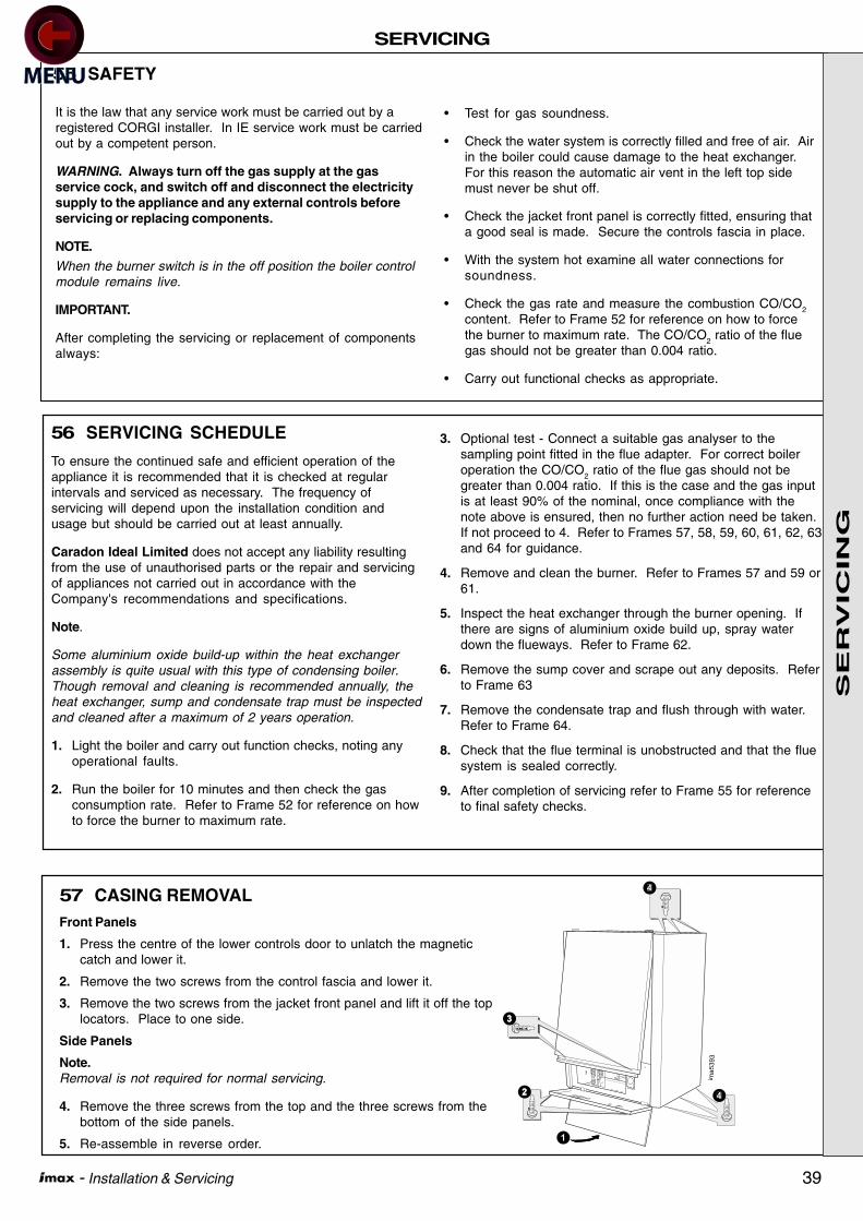
39 - Installation & Servicing
SERVICING
55 SAFETY
It is the law that any service work must be carried out by aregistered CORGI installer. In IE service work must be carriedout by a competent person.
WARNING. Always turn off the gas supply at the gasservice cock, and switch off and disconnect the electricitysupply to the appliance and any external controls beforeservicing or replacing components.
NOTE.
When the burner switch is in the off position the boiler controlmodule remains live.
IMPORTANT.
After completing the servicing or replacement of componentsalways:
• Test for gas soundness.
• Check the water system is correctly filled and free of air. Airin the boiler could cause damage to the heat exchanger.For this reason the automatic air vent in the left top sidemust never be shut off.
• Check the jacket front panel is correctly fitted, ensuring thata good seal is made. Secure the controls fascia in place.
• With the system hot examine all water connections forsoundness.
• Check the gas rate and measure the combustion CO/CO2
content. Refer to Frame 52 for reference on how to forcethe burner to maximum rate. The CO/CO2 ratio of the fluegas should not be greater than 0.004 ratio.
• Carry out functional checks as appropriate.
56 SERVICING SCHEDULE
To ensure the continued safe and efficient operation of theappliance it is recommended that it is checked at regularintervals and serviced as necessary. The frequency ofservicing will depend upon the installation condition andusage but should be carried out at least annually.
Caradon Ideal Limited does not accept any liability resultingfrom the use of unauthorised parts or the repair and servicingof appliances not carried out in accordance with theCompany's recommendations and specifications.
Note.
Some aluminium oxide build-up within the heat exchangerassembly is quite usual with this type of condensing boiler.Though removal and cleaning is recommended annually, theheat exchanger, sump and condensate trap must be inspectedand cleaned after a maximum of 2 years operation.
1. Light the boiler and carry out function checks, noting anyoperational faults.
2. Run the boiler for 10 minutes and then check the gasconsumption rate. Refer to Frame 52 for reference on howto force the burner to maximum rate.
3. Optional test - Connect a suitable gas analyser to thesampling point fitted in the flue adapter. For correct boileroperation the CO/CO2 ratio of the flue gas should not begreater than 0.004 ratio. If this is the case and the gas inputis at least 90% of the nominal, once compliance with thenote above is ensured, then no further action need be taken.If not proceed to 4. Refer to Frames 57, 58, 59, 60, 61, 62, 63and 64 for guidance.
4. Remove and clean the burner. Refer to Frames 57 and 59 or61.
5. Inspect the heat exchanger through the burner opening. Ifthere are signs of aluminium oxide build up, spray waterdown the flueways. Refer to Frame 62.
6. Remove the sump cover and scrape out any deposits. Referto Frame 63
7. Remove the condensate trap and flush through with water.Refer to Frame 64.
8. Check that the flue terminal is unobstructed and that the fluesystem is sealed correctly.
9. After completion of servicing refer to Frame 55 for referenceto final safety checks.
57 CASING REMOVALFront Panels
1. Press the centre of the lower controls door to unlatch the magneticcatch and lower it.
2. Remove the two screws from the control fascia and lower it.
3. Remove the two screws from the jacket front panel and lift it off the toplocators. Place to one side.
Side Panels
Note.Removal is not required for normal servicing.
4. Remove the three screws from the top and the three screws from thebottom of the side panels.
5. Re-assemble in reverse order.
ima5393
1
4
4
SE
RV
ICIN
G

40 - Installation & Servicing
SERVICING
59 BURNER REMOVAL - W45, W60, W45P AND W60P1. Remove the jacket front panel. Refer to Frame 57.
2. Remove fan, burner and gas valve assembly. Refer toFrame 58.
3. The burner can now be removed.
The burner can be cleaned using a soft brush, but only onthe back face. The metal fibre surface must not bebrushed. If the burner is showing any signs of damage itshould be replaced.
4. After cleaning the burner, the sealing gasket can be re-used providing it shows no sign of damage. If it isdamaged it must be replaced. On models with a ribbedgasket, ensure that it is correctly retained within the burnerhood.
5. Reassemble in reverse order.
6. Check the operation of the boiler. Refer to Frame 55.
58 REMOVAL OF FAN, BURNER AND GAS VALVE ASSEMBLY- W45, W60, W45P AND W60P
1. Remove the jacket front panel, Refer to Frame 57.
2. Disconnect the electrical connections from the gas valve.
3. Disconnect the electrical connection from the fan.
4. Undo the gas valve nut and retain the fibre washer.
5. Remove the eight nuts and washers securing the assembly to thecombustion chamber.
6. Pull off the H.T. lead to the spark/detection electrode.
7. Carefully remove the complete assembly taking care not to damagethe spark/detection electrode.
8. Re-assemble in reverse order. The burner sealing gasket can be re-used providing it shows no sign of damage. The eight nuts andwashers should be fitted following a diagonal tightening sequencetwice. The nuts should be secured firmly. Replace the fibre washeras necessary.
9. Check the operation of the boiler. Refer to Frame 55.
5
5
4
im 2514
Fan
60 REMOVAL OF FAN, BURNER AND GAS VALVE ASSEMBLY - W80/W80P1. Remove the jacket front panel, refer to Frame 57.
2. Disconnect the electrical connections from both gas valves.
3. Pull off the high and low pressure sensing pipes from theassembly.
4. Disconnect both electrical connections from the fan.
5. Undo both gas valve nuts and retain the fibre washers.
6. Undo the gas pipe connector nut, retaining the fibrewasher, and remove the upper gas pipe.
7. Pull off the H.T. lead to the spark/detection electrode.
8. Remove the eight nuts and washers securing theassembly to the combustion chamber.
9. Carefully remove the complete assembly taking care not todamage the spark/detection electrode with the assembly.
10. Re-assemble in reverse order. The burner gasket can bere-used provided it shows no signs of damage. The eightnuts and washers should be fitted following a diagonaltightening sequence twice. The nuts should be securedfirmly. Replace the fibre washers as necessary.
6
8
3
3
85
(Red)
(Blue)
im 2506
11. Check the operation of the boiler. Refer to Frame 55.
Burner hood
Combustion
chamber
Gasket
(early models
only)
Gasket Ribbed
(later models
only)Burner
im 5765
3
SE
RV
ICIN
G

41 - Installation & Servicing
SERVICING
im55
63
4
1. Remove the jacket front panel. Refer to Frame 57.
2. Remove fan, burner and gas valve assembly. Referto Frame 60.
3. The burner can now be removed.
The burner can be cleaned using a soft brush, butonly on the back face. The metal fibre surface mustnot be brushed. If the burner is showing any signs ofdamage it should be replaced.
4. After cleaning the burner, the sealing gasket can bere-used providing it shows no sign of damage. If it isdamaged it must be replaced. On models with aribbed gasket, ensure that it is correctly retainedwithin the burner hood.
5. Reassemble in reverse order.
6. Check the operation of the boiler. Refer to Frame 55.
61 BURNER REMOVAL - W80/W80P
Burner hood
Combustion
chamber
Burner
im 2
52
4
62 HEAT EXCHANGER INSPECTION / CLEANING
1. Remove the jacket front panel. Refer to Frame57.
2. Remove the fan, burner and gas valveassembly. Refer to Frame 58 or 60.
3. Inspect the heat exchanger for signs ofaluminium oxide build up. If necessary, cleanthe heat exchanger by spraying water down theflueways.
4. Reassemble in reverse order.
5. Check the operation of the boiler. Refer toFrame 55.
63 REMOVAL OF SUMP COVER
1. Remove the jacket front panel. Refer to Frame 57.
2. Disconnect HT Lead and earth lead from the ignition/detection probe.
3. Make Adequate provision to protect boiler from waterspillage.
4. Undo 6 nuts and washers and remove sump cover.
5. Scrape out any deposits.
6. Reassemble in reverse order using a new sump covergasket if it shows any signs of damage.
7. Check the operation of the boiler. Refer to Frame 55.
Burner hood
Combustion
chamber
Burner
im 5766
3
Gasket
(early models
only)
Gasket Ribbed
(later models
only)
SE
RV
ICIN
G

42 - Installation & Servicing
SERVICING
64 CONDENSATE TRAP
1. Unscrew the nut and disconnect the flexible pipe.
2. Unscrew the nut and remove the condensate trap.
3. Remove the nut and plug from the condensate trapand flush out with water.
4. Reassemble in reverse order ensuring thecondensate trap is full of water before firing.
5. Check the operation of the appliance. Refer toFrame 55.
ima5568
1
3
2
Refer to Frame 55, then:
1. Remove the jacket front panel. Refer to Frame 57.
2. Disconnect the electrical connections from the gas valve.
3. Disconnect the electrical connections from the fan.
4. Undo the gas valve nut and retain the fibre washer.
5. Remove the four nuts securing the fan to the burner hoodand lift out of the boiler.
6. Remove the 2 screws securing the venturi to the fan inlet.
7. Replace the fan using the new gaskets and fibre washeras supplied.
8. Re-assemble in reverse order.
9. Check the operation of the boiler. Refer to Frame 55.
65 FAN REPLACEMENT - W45, W60, W45P AND W60P
66 FAN REPLACEMENT - W80/W80P
Refer to Frame 55, then:
1. Remove the jacket front panel. Refer to Frame 57.
2. Remove fan, burner and gas valve assembly.Refer to Frame 60.
3. Remove the four screws securing the gas manifoldto the fan.
4. Remove the four nuts securing the fan to the burnerhood.
5. Replace the fan with the new gaskets and fibrewashers as supplied.
6. Reassemble in reverse order.
7. Check the operation of the boiler. Refer to Frame55.
4
3Fan
im 2508
5
Fan
im 2516
SE
RV
ICIN
G
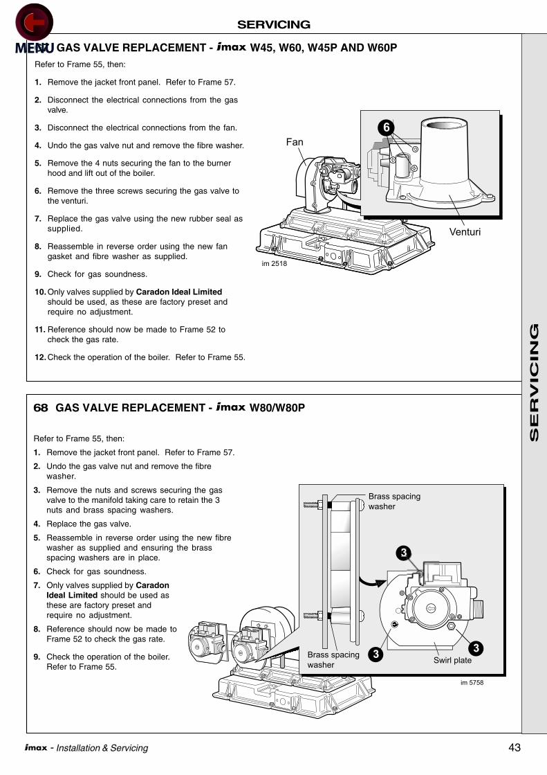
43 - Installation & Servicing
SERVICING
6
Fan
im 2518
Venturi
68 GAS VALVE REPLACEMENT - W80/W80P
67 GAS VALVE REPLACEMENT - W45, W60, W45P AND W60PRefer to Frame 55, then:
1. Remove the jacket front panel. Refer to Frame 57.
2. Disconnect the electrical connections from the gasvalve.
3. Disconnect the electrical connections from the fan.
4. Undo the gas valve nut and remove the fibre washer.
5. Remove the 4 nuts securing the fan to the burnerhood and lift out of the boiler.
6. Remove the three screws securing the gas valve tothe venturi.
7. Replace the gas valve using the new rubber seal assupplied.
8. Reassemble in reverse order using the new fangasket and fibre washer as supplied.
9. Check for gas soundness.
10. Only valves supplied by Caradon Ideal Limitedshould be used, as these are factory preset andrequire no adjustment.
11. Reference should now be made to Frame 52 tocheck the gas rate.
12. Check the operation of the boiler. Refer to Frame 55.
im 5758
3
3
Swirl plate3
Brass spacing
washer
Brass spacing
washer
Refer to Frame 55, then:
1. Remove the jacket front panel. Refer to Frame 57.
2. Undo the gas valve nut and remove the fibrewasher.
3. Remove the nuts and screws securing the gasvalve to the manifold taking care to retain the 3nuts and brass spacing washers.
4. Replace the gas valve.
5. Reassemble in reverse order using the new fibrewasher as supplied and ensuring the brassspacing washers are in place.
6. Check for gas soundness.
7. Only valves supplied by CaradonIdeal Limited should be used asthese are factory preset andrequire no adjustment.
8. Reference should now be made toFrame 52 to check the gas rate.
9. Check the operation of the boiler.Refer to Frame 55.
SE
RV
ICIN
G

44 - Installation & Servicing
SERVICING
69 VENTURI REPLACEMENT
Refer to Frame 55, then:
1. Remove the jacket front panel. Refer to Frame 57.
2. Disconnect the electrical connections from the gasvalve.
3. Disconnect the electrical connections from the fan.
4. Undo the gas valve nut and remove the fibre washer.
5. Remove the 4 nuts securing the fan to the burner hoodand lift out of the boiler.
6. Remove the 3 screws securing the gas valve to theventuri.
7. Remove the 2 screws securing the venturi to the fan.
8. Re-assemble in reverse order using the new sealsand gaskets as supplied.
9. Check for gas soundness.
10. Only Venturi's supplied by Caradon Ideal Limitedshould be used as these are factory preset andrequire no adjustment.
11. Reference should now be made to Frame 52 to checkthe gas rate.
12. Check the operation of the boiler. Refer to frame 55.
6
10
Fan
im 2541
Venturi
70 AIR PRESSURE SWITCH REPLACEMENT - W80/W80P
Refer to Frame 55, then:
1. Remove the jacket front panel.Refer to Frame 57.
2. Remove the two sensing pipesfrom the air pressure switch.
3. Pull off the two electricalconnectors.
4. Remove the two self tappingscrews.
5. Replace the air pressure switchand re-assemble in reverse order.
Note. The electrical connectors areconnected to the terminals marked Cand NO.
6. Check out the operation of theboiler. Refer to Frame 55.
im55
62
4
2Blue
Red
SE
RV
ICIN
G

45 - Installation & Servicing
SERVICING
71 IGNITION/DETECTION ELECTRODE TESTING/REPLACEMENT
3
im 2
520Refer to Frame 55, then:
1. Lower the controls fascia. Refer to Frame 57.
2. It is possible to measure the ionisation current witha voltmeter set at 0-10VDC. (0-10VDC = 0-10 microamps ionisation current).
3. With the boiler running, connect a meter betweenthe terminal marked and earth.
4. Normal reading should be between 4-8V (4-8µA).
5. Replace the electrode if the reading is 3V or below.
6. To replace the ignition/detection electrode, first
7
8
im 2519
remove the jacket front panel. Refer to Frame 57.
7. Pull the HT lead off the electrode.
8. Remove the 2 screws
9. Replace the electrode using the new gasket providedensuring that the earth lead is recaptivated under thescrew and washer.
10. Check the electrode gap is 3.5mm.
11. Re-assemble in reverse order.
12. Check the operation of the boiler. Refer to Frame 55.
72 AUTOMATIC AIR VENT REMOVAL
Refer to Frame 55, then:
1. Remove the jacket front panel. Refer to Frame57.
2. Unscrew the air vent from the self sealing fittingon the LHS of the flow manifold.
3. Replace the air vent.
4. Ensure that the black plastic vent cap is loose toallow air to escape. Air in the boiler could causedamage to the heat exchanger.
5. Reassemble in reverse order.
6. Check the operation of the boiler. Refer to Frame55.
im55
61
2
SE
RV
ICIN
G

46 - Installation & Servicing
SERVICING
im 5
560
4
74 WATER PRESSURE SWITCH REPLACEMENT
Refer to Frame 55, then:
1. Remove the jacket front panel. Refer to Frame 57.
2. Isolate water circuit and drain system
3. Disconnect the electrical connections from thepressure switch.
4. Unscrew the water pressure switch
5. Fit the new water pressure switch.
6. Re-fill the system ensuring all the air in the heatexchanger is vented through the air vent.
7. Re-assemble in reverse order.
8. Check the operation of the boiler. Refer to Frame55.
73 PRESSURE GAUGE REPLACEMENT
Refer to Frame 55, then:
1. Remove the jacket front panel. Refer to Frame 57.
2. Unscrew the nut retaining the capillary from the self sealingfitting.
3. Unscrew the two screws from the pressure gauge bracketand withdraw the unit from the boiler.
4. Compress the retaining lugs and remove the gauge fromthe bracket.
5. Replace the pressure gauge using the fresh gasketsupplied.
6. Reassemble in reverse order.
7. Check the operation of the boiler. Refer to Frame 55.
75 FLOW / RETURN THERMISTOR REMOVAL
Refer to Frame 55, then:
1. Remove the jacket front panel. Refer to Frame 57.
2. Isolate water circuit and drain system
3. Disconnect the electrical connections from thethermistor.
4. Unscrew the thermistor.
5. Fit the new thermistor with built in ‘O‘ ring seal. Donot overtighten.
6. Refill the system ensuring all the air in the heatexchanger is vented through the air vent.
7. Re-assemble in reverse order.
8. Check the operation of the boiler. Refer to Frame 55.
ima5393
4
3
im 5
559
4
SE
RV
ICIN
G

47 - Installation & Servicing
SERVICING
Refer to Frame 55, then:
1. Lower the controls fascia. Refer to Frame 57.
2. Disconnect the transformer connection from theboiler control module.
3. Remove the four transformer mounting screws.
4. Fit new transformer.
5. Reassemble in reverse order.
6. Check the operation of the boiler. Refer to Frame55.
76 TRANSFORMER REMOVAL
77 BOILER CONTROL MODULE REMOVAL
Refer to Frame 55, then:
1. Lower the controls fascia. Refer to Frame 57.
2. To facilitate the removal of the boiler control module itwill be necessary first to remove the transformer. Referto Frame 76.
3. Disconnect the electrical connections from the module.
4. Remove the four module fixing screws.
5. Fit the new module and reassemble in reverse order.
6. Check the operation of the boiler. Refer to Frame 55.
78 DISPLAY BOARD REMOVAL
Refer to Frame 55, then:
1. Lower the controls fascia. Refer to Frame 57.
2. Disconnect the electrical connection from the displayboard.
3. Undo and remove the 4 plastic nuts.
4. Lift the display board from the 4 studs being careful not todisturb the loose fitted plastic sleeves.
5. Fit the new display board and re-assemble in reverseorder.
6. Check the operation of the boiler. Refer to Frame 55.
im 2
521
Transformer
3
im 2522
Transformer
4
im 2522
3
Spacer
SE
RV
ICIN
G
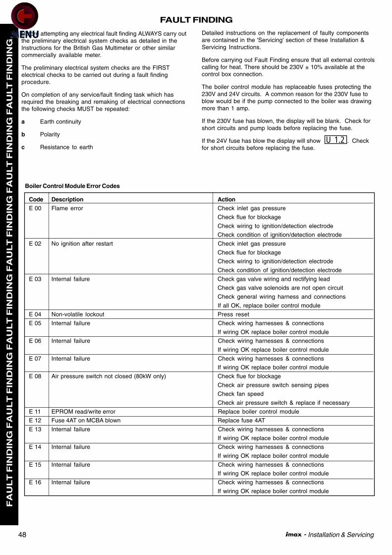
48 - Installation & Servicing
FAULT FINDING F
AU
LT
FIN
DIN
G F
AU
LT
FIN
DIN
G F
AU
LT
FIN
DIN
G F
AU
LT
FIN
DIN
G F
AU
LT
FIN
DIN
G F
AU
LT
FIN
DIN
G
Before attempting any electrical fault finding ALWAYS carry outthe preliminary electrical system checks as detailed in theInstructions for the British Gas Multimeter or other similarcommercially available meter.
The preliminary electrical system checks are the FIRSTelectrical checks to be carried out during a fault findingprocedure.
On completion of any service/fault finding task which hasrequired the breaking and remaking of electrical connectionsthe following checks MUST be repeated:
a Earth continuity
b Polarity
c Resistance to earth
Detailed instructions on the replacement of faulty componentsare contained in the 'Servicing' section of these Installation &Servicing Instructions.
Before carrying out Fault Finding ensure that all external controlscalling for heat. There should be 230V ± 10% available at thecontrol box connection.
The boiler control module has replaceable fuses protecting the230V and 24V circuits. A common reason for the 230V fuse toblow would be if the pump connected to the boiler was drawingmore than 1 amp.
If the 230V fuse has blown, the display will be blank. Check forshort circuits and pump loads before replacing the fuse.
If the 24V fuse has blow the display will show . Checkfor short circuits before replacing the fuse.
Code Description ActionE 00 Flame error Check inlet gas pressure
Check flue for blockage
Check wiring to ignition/detection electrode
Check condition of ignition/detection electrode
E 02 No ignition after restart Check inlet gas pressure
Check flue for blockage
Check wiring to ignition/detection electrode
Check condition of ignition/detection electrode
E 03 Internal failure Check gas valve wiring and rectifying lead
Check gas valve solenoids are not open circuit
Check general wiring harness and connections
If all OK, replace boiler control module
E 04 Non-volatile lockout Press reset
E 05 Internal failure Check wiring harnesses & connections
If wiring OK replace boiler control module
E 06 Internal failure Check wiring harnesses & connections
If wiring OK replace boiler control module
E 07 Internal failure Check wiring harnesses & connections
If wiring OK replace boiler control module
E 08 Air pressure switch not closed (80kW only) Check flue for blockage
Check air pressure switch sensing pipes
Check fan speed
Check air pressure switch & replace if necessary
E 11 EPROM read/write error Replace boiler control module
E 12 Fuse 4AT on MCBA blown Replace fuse 4AT
E 13 Internal failure Check wiring harnesses & connections
If wiring OK replace boiler control module
E 14 Internal failure Check wiring harnesses & connections
If wiring OK replace boiler control module
E 15 Internal failure Check wiring harnesses & connections
If wiring OK replace boiler control module
E 16 Internal failure Check wiring harnesses & connections
If wiring OK replace boiler control module
Boiler Control Module Error Codes
U 1.2

49 - Installation & Servicing
FAULT FINDING
FA
ULT
FIN
DIN
G F
AU
LT
FIN
DIN
G F
AU
LT
FIN
DIN
G F
AU
LT
FIN
DIN
G F
AU
LT
FIN
DIN
G F
AU
LT
FIN
DIN
G
Code Description ActionE 17 Internal failure Check wiring harnesses & connections
If wiring OK replace boiler control module
E 18 Flow temperature too high Check no air in system or boiler
Check adequate flow of water through boiler
E 19 Return temperature too high Check no air in system or boiler
Check adequate flow of water through boiler
E 25 Flow temperature rise too fast Check no air in system or boiler
Check adequate flow of water through boiler
E 28 No tacho from fan Check electrical connections to fan
If connections OK & fan rotates, replace fan
E 29 Tacho signal from fan does not reset to zero Replace fan
E 30 Flow/return temperature differential too high Check no air in system or boiler
Check adequate flow of water through boiler
E 31 Flow thermister short circuit Check wiring
Disconnect terminals from thermistor & confirm
short circuit using meter
Replace thermister
E 32 Return thermistor short circuit Check wiring
Disconnect terminals from thermister & confirm
short circuit using meter
Replace thermister
E 33 DHW thermistor short circuit Check wiring
Disconnect terminals from thermister & confirm
short circuit using meter
Replace thermister
E 36 Flow thermistor open circuit Check wiring
Disconnect terminals from thermister & confirm
open circuit using meter
Replace thermister
E 37 Return thermistor open circuit Check wiring
Disconnect terminals from thermister & confirm
open circuit using meter
Replace thermister
E 38 Tank sensor open circuit If not fitted check parameter 35 settings
Check wiring
Disconnect terminals from tank sensor & confirm
open circuit using meter
Replace tank sensor
E 44 Internal failure Check wiring harnesses & connections
If wiring OK replace boiler control module
E 60 Error reading parameters Replace boiler control module
E 61 Air pressure switch does not open (W80 only) Check for blockages in air pressure switch
sensing pipes
Check air pressure switch & replace if necessary
E 65 Not enough fan driving force Check supply voltage to fan
Replace fan
Boiler Control Module Error Codes Continued
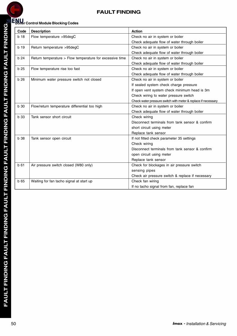
50 - Installation & Servicing
FAULT FINDING F
AU
LT
FIN
DIN
G F
AU
LT
FIN
DIN
G F
AU
LT
FIN
DIN
G F
AU
LT
FIN
DIN
G F
AU
LT
FIN
DIN
G F
AU
LT
FIN
DIN
G
Code Description Action
b 18 Flow temperature >95degC Check no air in system or boiler
Check adequate flow of water through boiler
b 19 Return temperature >95degC Check no air in system or boiler
Check adequate flow of water through boiler
b 24 Return temperature > Flow temperature for excessive time Check no air in system or boiler
Check adequate flow of water through boiler
b 25 Flow temperature rise too fast Check no air in system or boiler
Check adequate flow of water through boiler
b 26 Minimum water pressure switch not closed Check no air in system or boiler
If sealed system check charge pressure
If open vent system check minimum head is 3m
Check wiring to water pressure switch
Check water pressure switch with meter & replace if necessary
b 30 Flow/return temperature differential too high Check no air in system or boiler
Check adequate flow of water through boiler
b 33 Tank sensor short circuit Check wiring
Disconnect terminals from tank sensor & confirm
short circuit using meter
Replace tank sensor
b 38 Tank sensor open circuit If not fitted check parameter 35 settings
Check wiring
Disconnect terminals from tank sensor & confirm
open circuit using meter
Replace tank sensor
b 61 Air pressure switch closed (W80 only) Check for blockages in air pressure switch
sensing pipes
Check air pressure switch & replace if necessary
b 65 Waiting for fan tacho signal at start up Check fan wiring
If no tacho signal from fan, replace fan
Boiler Control Module Blocking Codes
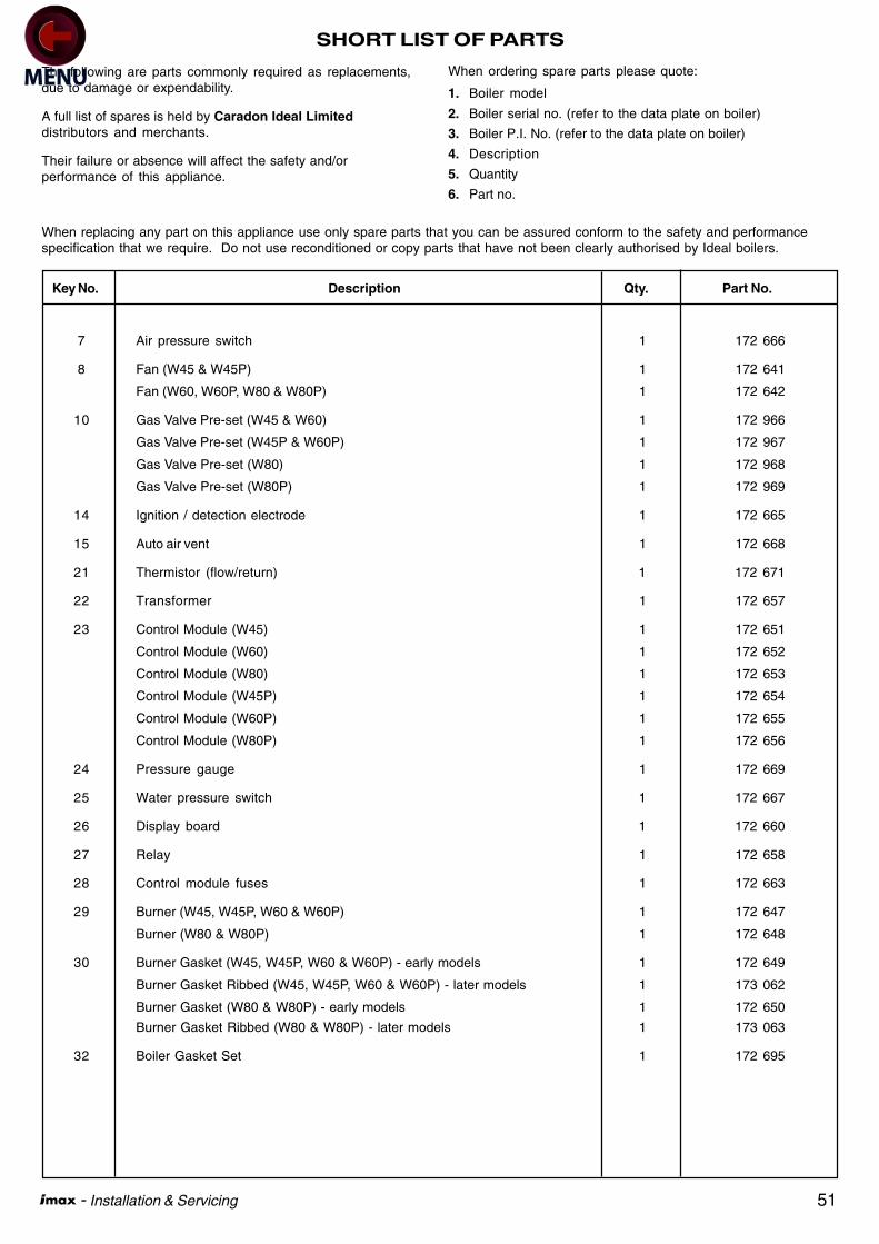
51 - Installation & Servicing
SHORT LIST OF PARTS
The following are parts commonly required as replacements,due to damage or expendability.
A full list of spares is held by Caradon Ideal Limiteddistributors and merchants.
Their failure or absence will affect the safety and/orperformance of this appliance.
When ordering spare parts please quote:
1. Boiler model
2. Boiler serial no. (refer to the data plate on boiler)
3. Boiler P.I. No. (refer to the data plate on boiler)
4. Description
5. Quantity
6. Part no.
Key No. Description Qty. Part No.
7 Air pressure switch 1 172 666
8 Fan (W45 & W45P) 1 172 641
Fan (W60, W60P, W80 & W80P) 1 172 642
10 Gas Valve Pre-set (W45 & W60) 1 172 966
Gas Valve Pre-set (W45P & W60P) 1 172 967
Gas Valve Pre-set (W80) 1 172 968
Gas Valve Pre-set (W80P) 1 172 969
14 Ignition / detection electrode 1 172 665
15 Auto air vent 1 172 668
21 Thermistor (flow/return) 1 172 671
22 Transformer 1 172 657
23 Control Module (W45) 1 172 651
Control Module (W60) 1 172 652
Control Module (W80) 1 172 653
Control Module (W45P) 1 172 654
Control Module (W60P) 1 172 655
Control Module (W80P) 1 172 656
24 Pressure gauge 1 172 669
25 Water pressure switch 1 172 667
26 Display board 1 172 660
27 Relay 1 172 658
28 Control module fuses 1 172 663
29 Burner (W45, W45P, W60 & W60P) 1 172 647
Burner (W80 & W80P) 1 172 648
30 Burner Gasket (W45, W45P, W60 & W60P) - early models 1 172 649
Burner Gasket Ribbed (W45, W45P, W60 & W60P) - later models 1 173 062
Burner Gasket (W80 & W80P) - early models 1 172 650
Burner Gasket Ribbed (W80 & W80P) - later models 1 173 063
32 Boiler Gasket Set 1 172 695
When replacing any part on this appliance use only spare parts that you can be assured conform to the safety and performancespecification that we require. Do not use reconditioned or copy parts that have not been clearly authorised by Ideal boilers.
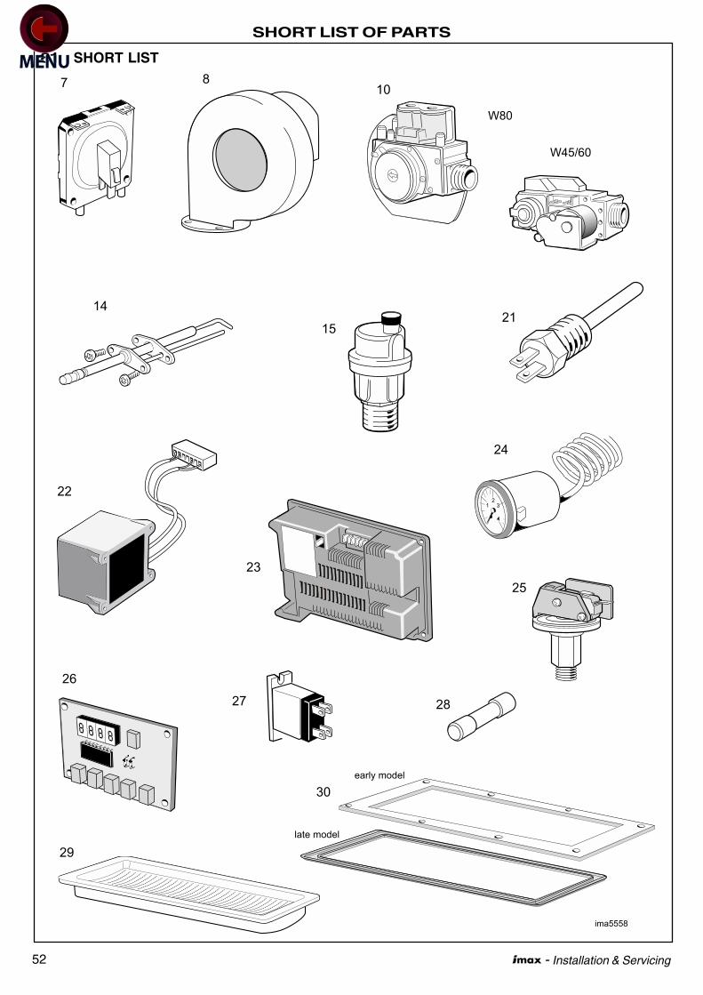
52 - Installation & Servicing
SHORT LIST OF PARTS
81 SHORT LIST
28
25
27
ima5558
14
1521
22
23
24
26
107 8
29
W80
W45/60
30
early model
late model

53 - Installation & Servicing
NOTES

54 - Installation & Servicing
NOTES

55 - Installation & Servicing
NOTES

Ideal Boilers, P.O. Box 103, National Ave, Kingston upon Hull,HU5 4JN. Telephone: 01482 492 251 Fax: 01482 448 858.Registration No. London 322 137.
May 2003 UIN 158 334 A03
Technical Training
Caradon Ideal Limited pursues a policy of continuingimprovement in the design and performance of its products. Theright is therefore reserved to vary specification without notice.
The Ideal Boilers Technical Training Centre offers a series of first class training courses for domestic, commercial andindustrial heating installers, engineers and system specifiers. For details of courses please ring: .......... 01482 498 432
Ideal Installer/Technical Helpline: 01482 498 376www.idealboilers.com