by capt. david rifkin (usn, ret.)qualitymarineservices.net/tranformers, polarization vs....
TRANSCRIPT
In this article we are going to sort through the ins and outs of transformer installation in a boat’s electrical system. There are two installation systems—polarization and isolation—both of which are diagramed in ABYC’s E-11 standard. Each will be discussed with an emphasis on the safety of personnel on the boat as well as in the water around the boat. Here’s a ques-tion to keep in mind while reading this article: Would you deliberately disconnect the green grounding wire from receptacles or appliances in your home?
A transformer is a device that transfers power from a primary winding (input) to a secondary winding (output) through the process of magnetic induction. This sec-ondary voltage is what powers the electrical loads on a boat without a direct connection to the electrical source ashore.
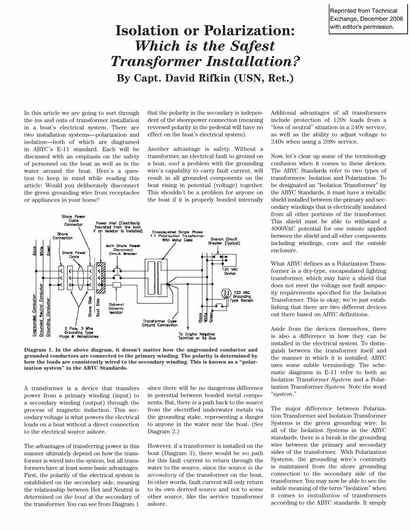
The advantages of transferring power in this manner ultimately depend on how the trans-former is wired into the system, but all trans-formers have at least some basic advantages. First, the polarity of the electrical system is established on the secondary side, meaning the relationship between Hot and Neutral is determined on the boat at the secondary of the transformer. You can see from Diagram 1
Isolation or Polarization: Which is the Safest
Transformer Installation?By Capt. David Rifkin (USN, Ret.)
that the polarity in the secondary is indepen-dent of the shorepower connection (meaning reversed polarity in the pedestal will have no effect on the boat’s electrical system).
Another advantage is safety. Without a transformer, an electrical fault to ground on a boat, and a problem with the grounding wire’s capability to carry fault current, will result in all grounded components on the boat rising in potential (voltage) together. This shouldn’t be a problem for anyone on the boat if it is properly bonded internally
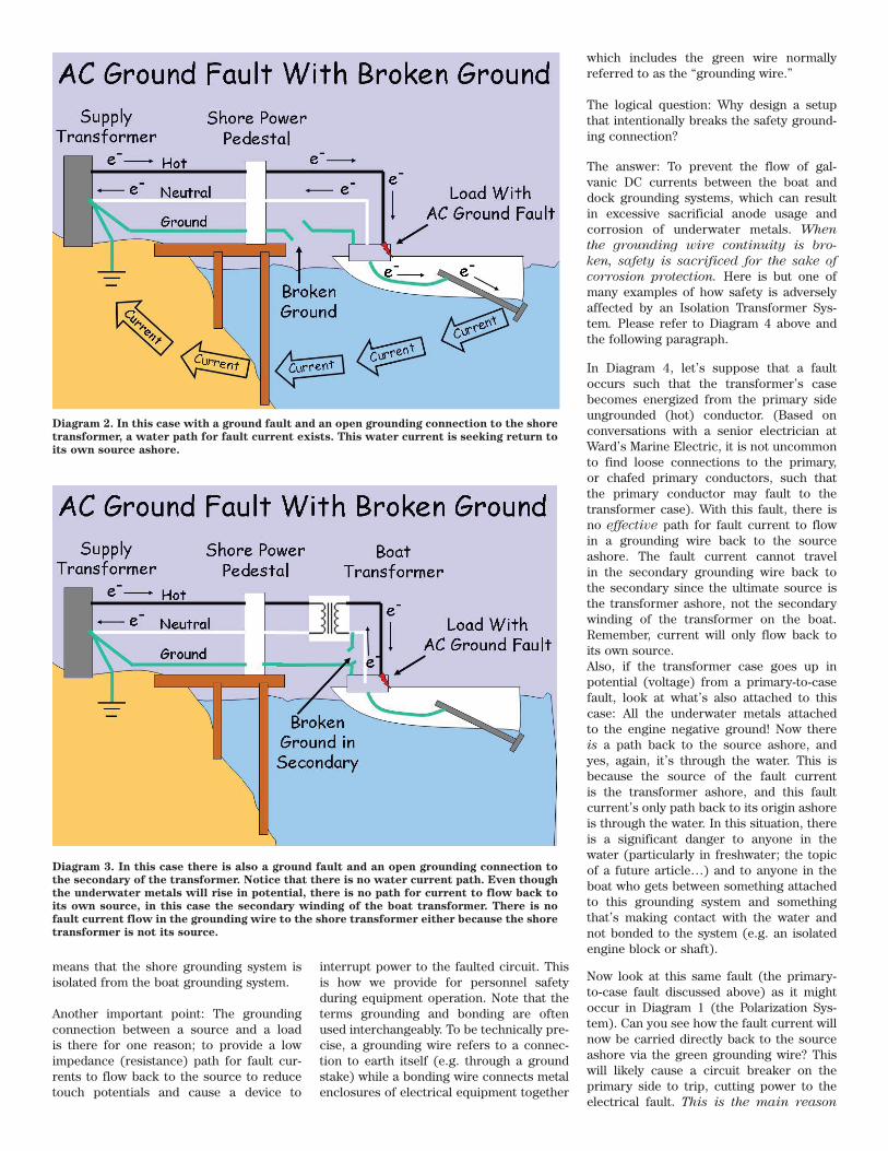
since there will be no dangerous difference in potential between bonded metal compo-nents. But, there is a path back to the source from the electrified underwater metals via the grounding stake, representing a danger to anyone in the water near the boat. (See Diagram 2.)
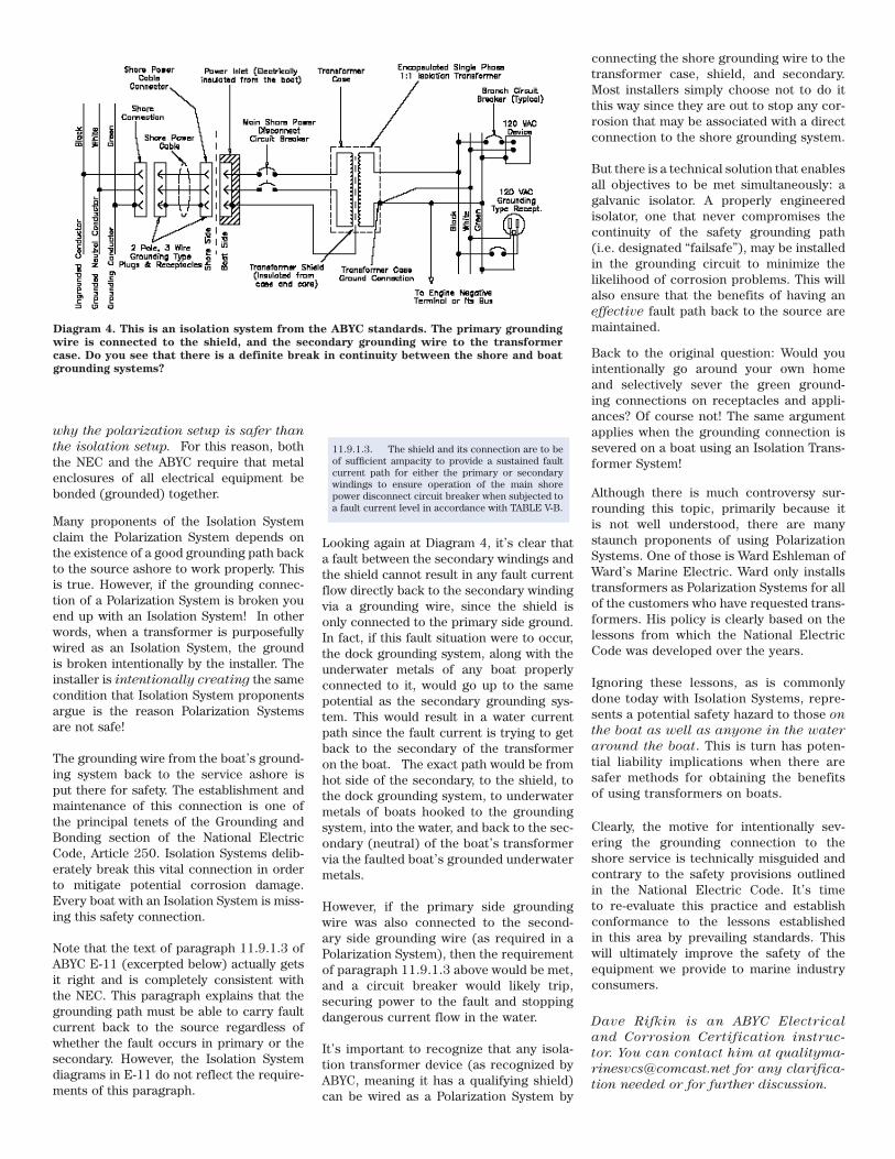
However, if a transformer is installed on the boat (Diagram 3), there would be no path for this fault current to return through the water to the source, since the source is the secondary of the transformer on the boat. In other words, fault current will only return to its own derived source and not to some other source, like the service transformer ashore.
Additonal advantages of all transformers include protection of 120v loads from a “loss of neutral” situation in a 240v service, as well as the ability to adjust voltage to 240v when using a 208v service.
Now, let’s clear up some of the terminology confusion when it comes to these devices. The ABYC Standards refer to two types of transformers: Isolation and Polarization. To be designated an “Isolation Transformer” by the ABYC Standards, it must have a metallic shield installed between the primary and sec-ondary windings that is electrically insulated from all other portions of the transformer. This shield must be able to withstand a 4000VAC potential for one minute applied between the shield and all other components including windings, core and the outside enclosure.
What ABYC defines as a Polarization Trans-former is a dry-type, encapsulated lighting transformer, which may have a shield that does not meet the voltage nor fault ampac-ity requirements specified for the Isolation Transformer. This is okay; we’re just estab-lishing that there are two different devices out there based on ABYC definitions.
Aside from the devices themselves, there is also a difference in how they can be installed in the electrical system. To distin-guish between the transformer itself and the manner in which it is installed, ABYC uses some subtle terminology. The sche-matic diagrams in E-11 refer to both an Isolation Transformer System and a Polar-ization Transformer System. Note the word “system.”
The major difference between Polariza-tion Transformer and Isolation Transformer Systems is the green grounding wire: In all of the Isolation Systems in the ABYC standards, there is a break in the grounding wire between the primary and secondary sides of the transformer. With Polarization Systems, the grounding wire’s continuity is maintained from the shore grounding connection to the secondary side of the transformer. You may now be able to see the subtle meaning of the term “Isolation” when it comes to installation of transformers according to the ABYC standards. It simply
Diagram 1. In the above diagram, it doesn’t matter how the ungrounded conductor and grounded conductors are connected to the primary winding. The polarity is determined by how the loads are consistently wired to the secondary winding. This is known as a “polar-ization system” in the ABYC Standards.
means that the shore grounding system is isolated from the boat grounding system.
Another important point: The grounding connection between a source and a load is there for one reason; to provide a low impedance (resistance) path for fault cur-rents to flow back to the source to reduce touch potentials and cause a device to
interrupt power to the faulted circuit. This is how we provide for personnel safety during equipment operation. Note that the terms grounding and bonding are often used interchangeably. To be technically pre-cise, a grounding wire refers to a connec-tion to earth itself (e.g. through a ground stake) while a bonding wire connects metal enclosures of electrical equipment together
which includes the green wire normally referred to as the “grounding wire.”
The logical question: Why design a setup that intentionally breaks the safety ground-ing connection?
The answer: To prevent the flow of gal-vanic DC currents between the boat and dock grounding systems, which can result in excessive sacrificial anode usage and corrosion of underwater metals. When the grounding wire continuity is bro-ken, safety is sacrificed for the sake of corrosion protection. Here is but one of many examples of how safety is adversely affected by an Isolation Transformer Sys-tem. Please refer to Diagram 4 above and the following paragraph.
In Diagram 4, let’s suppose that a fault occurs such that the transformer’s case becomes energized from the primary side ungrounded (hot) conductor. (Based on conversations with a senior electrician at Ward’s Marine Electric, it is not uncommon to find loose connections to the primary, or chafed primary conductors, such that the primary conductor may fault to the transformer case). With this fault, there is no effective path for fault current to flow in a grounding wire back to the source ashore. The fault current cannot travel in the secondary grounding wire back to the secondary since the ultimate source is the transformer ashore, not the secondary winding of the transformer on the boat. Remember, current will only flow back to its own source.Also, if the transformer case goes up in potential (voltage) from a primary-to-case fault, look at what’s also attached to this case: All the underwater metals attached to the engine negative ground! Now there is a path back to the source ashore, and yes, again, it’s through the water. This is because the source of the fault current is the transformer ashore, and this fault current’s only path back to its origin ashore is through the water. In this situation, there is a significant danger to anyone in the water (particularly in freshwater; the topic of a future article…) and to anyone in the boat who gets between something attached to this grounding system and something that’s making contact with the water and not bonded to the system (e.g. an isolated engine block or shaft).
Now look at this same fault (the primary-to-case fault discussed above) as it might occur in Diagram 1 (the Polarization Sys-tem). Can you see how the fault current will now be carried directly back to the source ashore via the green grounding wire? This will likely cause a circuit breaker on the primary side to trip, cutting power to the electrical fault. This is the main reason
Diagram 2. In this case with a ground fault and an open grounding connection to the shore transformer, a water path for fault current exists. This water current is seeking return to its own source ashore.
Diagram 3. In this case there is also a ground fault and an open grounding connection to the secondary of the transformer. Notice that there is no water current path. Even though the underwater metals will rise in potential, there is no path for current to flow back to its own source, in this case the secondary winding of the boat transformer. There is no fault current flow in the grounding wire to the shore transformer either because the shore transformer is not its source.
why the polarization setup is safer than the isolation setup. For this reason, both the NEC and the ABYC require that metal enclosures of all electrical equipment be bonded (grounded) together.
Many proponents of the Isolation System claim the Polarization System depends on the existence of a good grounding path back to the source ashore to work properly. This is true. However, if the grounding connec-tion of a Polarization System is broken you end up with an Isolation System! In other words, when a transformer is purposefully wired as an Isolation System, the ground is broken intentionally by the installer. The installer is intentionally creating the same condition that Isolation System proponents argue is the reason Polarization Systems are not safe!
The grounding wire from the boat’s ground-ing system back to the service ashore is put there for safety. The establishment and maintenance of this connection is one of the principal tenets of the Grounding and Bonding section of the National Electric Code, Article 250. Isolation Systems delib-erately break this vital connection in order to mitigate potential corrosion damage. Every boat with an Isolation System is miss-ing this safety connection.
Note that the text of paragraph 11.9.1.3 of ABYC E-11 (excerpted below) actually gets it right and is completely consistent with the NEC. This paragraph explains that the grounding path must be able to carry fault current back to the source regardless of whether the fault occurs in primary or the secondary. However, the Isolation System diagrams in E-11 do not reflect the require-ments of this paragraph.
Looking again at Diagram 4, it’s clear that a fault between the secondary windings and the shield cannot result in any fault current flow directly back to the secondary winding via a grounding wire, since the shield is only connected to the primary side ground. In fact, if this fault situation were to occur, the dock grounding system, along with the underwater metals of any boat properly connected to it, would go up to the same potential as the secondary grounding sys-tem. This would result in a water current path since the fault current is trying to get back to the secondary of the transformer on the boat. The exact path would be from hot side of the secondary, to the shield, to the dock grounding system, to underwater metals of boats hooked to the grounding system, into the water, and back to the sec-ondary (neutral) of the boat’s transformer via the faulted boat’s grounded underwater metals.
However, if the primary side grounding wire was also connected to the second-ary side grounding wire (as required in a Polarization System), then the requirement of paragraph 11.9.1.3 above would be met, and a circuit breaker would likely trip, securing power to the fault and stopping dangerous current flow in the water.
It’s important to recognize that any isola-tion transformer device (as recognized by ABYC, meaning it has a qualifying shield) can be wired as a Polarization System by
connecting the shore grounding wire to the transformer case, shield, and secondary. Most installers simply choose not to do it this way since they are out to stop any cor-rosion that may be associated with a direct connection to the shore grounding system.
But there is a technical solution that enables all objectives to be met simultaneously: a galvanic isolator. A properly engineered isolator, one that never compromises the continuity of the safety grounding path (i.e. designated “failsafe”), may be installed in the grounding circuit to minimize the likelihood of corrosion problems. This will also ensure that the benefits of having an effective fault path back to the source are maintained.
Back to the original question: Would you intentionally go around your own home and selectively sever the green ground-ing connections on receptacles and appli-ances? Of course not! The same argument applies when the grounding connection is severed on a boat using an Isolation Trans-former System!
Although there is much controversy sur-rounding this topic, primarily because it is not well understood, there are many staunch proponents of using Polarization Systems. One of those is Ward Eshleman of Ward’s Marine Electric. Ward only installs transformers as Polarization Systems for all of the customers who have requested trans-formers. His policy is clearly based on the lessons from which the National Electric Code was developed over the years.
Ignoring these lessons, as is commonly done today with Isolation Systems, repre-sents a potential safety hazard to those on the boat as well as anyone in the water around the boat. This is turn has poten-tial liability implications when there are safer methods for obtaining the benefits of using transformers on boats.
Clearly, the motive for intentionally sev-ering the grounding connection to the shore service is technically misguided and contrary to the safety provisions outlined in the National Electric Code. It’s time to re-evaluate this practice and establish conformance to the lessons established in this area by prevailing standards. This will ultimately improve the safety of the equipment we provide to marine industry consumers.
Dave Rifkin is an ABYC Electrical and Corrosion Certification instruc-tor. You can contact him at [email protected] for any clarifica-tion needed or for further discussion.
Diagram 4. This is an isolation system from the ABYC standards. The primary grounding wire is connected to the shield, and the secondary grounding wire to the transformer case. Do you see that there is a definite break in continuity between the shore and boat grounding systems?
11.9.1.3. The shield and its connection are to be of sufficient ampacity to provide a sustained fault current path for either the primary or secondary windings to ensure operation of the main shore power disconnect circuit breaker when subjected to a fault current level in accordance with TABLE V-B.