butcher guitar amplifier
TRANSCRIPT

www.peavey.com
Butcher™ Guitar Amplifier
OperatingManual
2
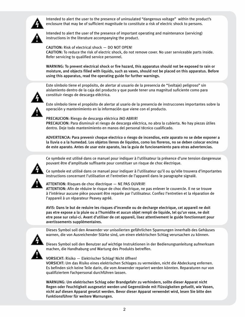
Intended to alert the user to the presence of uninsulated “dangerous voltage” within the product’s enclosure that may be of sufficient magnitude to constitute a risk of electric shock to persons.
Intended to alert the user of the presence of important operating and maintenance (servicing) instructions in the literature accompanying the product.
CAUTION: Risk of electrical shock — DO NOT OPEN! CAUTION: To reduce the risk of electric shock, do not remove cover. No user serviceable parts inside. Refer servicing to qualified service personnel.
WARNING: To prevent electrical shock or fire hazard, this apparatus should not be exposed to rain or moisture‚ and objects filled with liquids‚ such as vases‚ should not be placed on this apparatus. Before using this apparatus‚ read the operating guide for further warnings.
Este símbolo tiene el propósito, de alertar al usuario de la presencia de “(voltaje) peligroso” sin aislamiento dentro de la caja del producto y que puede tener una magnitud suficiente como para constituir riesgo de descarga eléctrica.
Este símbolo tiene el propósito de alertar al usario de la presencia de instruccones importantes sobre la operación y mantenimiento en la información que viene con el producto.
PRECAUCION: Riesgo de descarga eléctrica ¡NO ABRIR! PRECAUCION: Para disminuír el riesgo de descarga eléctrica, no abra la cubierta. No hay piezas útiles dentro. Deje todo mantenimiento en manos del personal técnico cualificado.
ADVERTENCIA: Para prevenir choque electrico o riesgo de incendios, este aparato no se debe exponer a la lluvia o a la humedad. Los objetos llenos de liquidos, como los floreros, no se deben colocar encima de este aparato. Antes de usar este aparato, lea la guia de funcionamiento para otras advertencias.
Ce symbole est utilisé dans ce manuel pour indiquer à l’utilisateur la présence d’une tension dangereuse pouvant être d’amplitude suffisante pour constituer un risque de choc électrique.
Ce symbole est utilisé dans ce manuel pour indiquer à l’utilisateur qu’il ou qu’elle trouvera d’importantes instructions concernant l’utilisation et l’entretien de l’appareil dans le paragraphe signalé.
ATTENTION: Risques de choc électrique — NE PAS OUVRIR!ATTENTION: Afin de réduire le risque de choc électrique, ne pas enlever le couvercle. Il ne se trouve à l’intérieur aucune pièce pouvant être reparée par l’utilisateur. Confiez I’entretien et la réparation de l’appareil à un réparateur Peavey agréé.
AVIS: Dans le but de reduire les risques d’incendie ou de decharge electrique, cet appareil ne doit pas etre expose a la pluie ou a l’humidite et aucun objet rempli de liquide, tel qu’un vase, ne doit etre pose sur celui-ci. Avant d’utiliser de cet appareil, lisez attentivement le guide fonctionnant pour avertissements supplémentaires.
Dieses Symbol soll den Anwender vor unisolierten gefährlichen Spannungen innerhalb des Gehäuses warnen, die von Ausreichender Stärke sind, um einen elektrischen Schlag verursachen zu können.
Dieses Symbol soll den Benutzer auf wichtige Instruktionen in der Bedienungsanleitung aufmerksam machen, die Handhabung und Wartung des Produkts betreffen.
VORSICHT: Risiko — Elektrischer Schlag! Nicht öffnen! VORSICHT: Um das Risiko eines elektrischen Schlages zu vermeiden, nicht die Abdeckung enfernen. Es befinden sich keine Teile darin, die vom Anwender repariert werden könnten. Reparaturen nur von qualifiziertem Fachpersonal durchführen lassen.
WARNUNG: Um elektrischen Schlag oder Brandgefahr zu verhindern, sollte dieser Apparat nicht Regen oder Feuchtigkeit ausgesetzt werden und Gegenstände mit Flüssigkeiten gefuellt, wie Vasen, nicht auf diesen Apparat gesetzt werden. Bevor dieser Apparat verwendet wird, lesen Sie bitte den Funktionsführer für weitere Warnungen.
3�
IMPORTANT SAFETY INSTRUCTIONS
WARNING: When using electrical products, basic cautions should always be followed, including the following:
1. Read these instructions.
2. Keep these instructions.
3. Heed all warnings.
4. Follow all instructions.
5. Do not use this apparatus near water.
6. Clean only with a dry cloth.
7. Do not block any of the ventilation openings. Install in accordance with manufacturer’s instructions.
8. Do not install near any heat sources such as radiators, heat registers, stoves or other apparatus (including amplifiers) that produce heat.
9. Do not defeat the safety purpose of the polarized or grounding-type plug. A polarized plug has two blades with one wider than the other. A grounding type plug has two blades and a third grounding plug. The wide blade or third prong is provided for your safety. If the provided plug does not fit into your outlet, consult an electrician for replacement of the obsolete outlet.
10. Protect the power cord from being walked on or pinched, particularly at plugs, convenience receptacles, and the point they exit from the apparatus.
11. Only use attachments/accessories provided by the manufacturer.
12. Use only with a cart, stand, tripod, bracket, or table specified by the manufacturer, or sold with the apparatus. When a cart is used, use caution when moving the cart/apparatus combination to avoid injury from tip-over.
13. Unplug this apparatus during lightning storms or when unused for long periods of time.
14. Refer all servicing to qualified service personnel. Servicing is required when the apparatus has been damaged in any way, such as power-supply cord or plug is damaged, liquid has been spilled or objects have fallen into the apparatus, the apparatus has been exposed to rain or moisture, does not operate normally, or has been dropped.
15. Never break off the ground pin. Write for our free booklet “Shock Hazard and Grounding.” Connect only to a power supply of the type marked on the unit adjacent to the power supply cord.
16. If this product is to be mounted in an equipment rack, rear support should be provided.
17. Note for UK only: If the colors of the wires in the mains lead of this unit do not correspond with the terminals in your plug‚ proceed as follows:
a) The wire that is colored green and yellow must be connected to the terminal that is marked by the letter E‚ the earth symbol‚ colored green or colored green and yellow.
b) The wire that is colored blue must be connected to the terminal that is marked with the letter N or the color black.
c) The wire that is colored brown must be connected to the terminal that is marked with the letter L or the color red.
18. This electrical apparatus should not be exposed to dripping or splashing and care should be taken not to place objects containing liquids, such as vases, upon the apparatus.
19. The on/off switch in this unit does not break both sides of the primary mains. Hazardous energy can be present inside the chassis when the on/off switch is in the off position. The mains plug or appliance coupler is used as the disconnect device, the disconnect device shall remain readily operable.
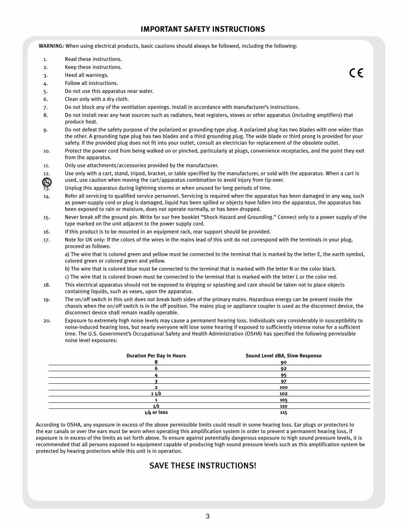
20. Exposure to extremely high noise levels may cause a permanent hearing loss. Individuals vary considerably in susceptibility to noise-induced hearing loss, but nearly everyone will lose some hearing if exposed to sufficiently intense noise for a sufficient time. The U.S. Government’s Occupational Safety and Health Administration (OSHA) has specified the following permissible noise level exposures:
Duration Per Day In Hours Sound Level dBA, Slow Response 8 90 6 92 4 95 3 97 2 100 1 1⁄2 102 1 105 1⁄2 110 1⁄4 or less 115
According to OSHA, any exposure in excess of the above permissible limits could result in some hearing loss. Ear plugs or protectors to the ear canals or over the ears must be worn when operating this amplification system in order to prevent a permanent hearing loss, if exposure is in excess of the limits as set forth above. To ensure against potentially dangerous exposure to high sound pressure levels, it is recommended that all persons exposed to equipment capable of producing high sound pressure levels such as this amplification system be protected by hearing protectors while this unit is in operation.
SAVE THESE INSTRUCTIONS!

4
�
WICHTIGE SICHERHEITSHINWEISE
ACHTUNG: Beim Einsatz von Elektrogeräten müssen u.a. grundlegende Vorsichtsmaßnahmen befolgt werden:
1. LesenSiesichdieseAnweisungendurch.
2. BewahrenSiedieseAnweisungenauf.
3. BeachtenSiealleWarnungen.
4. BefolgenSiealleAnweisungen.
5. SetzenSiediesesGerätnichtinderNähevonWasserein.
6. ReinigenSieesnurmiteinemtrockenenTuch.
7. BlockierenSiekeinederLüftungsöffnungen.FührenSiedieInstallationgemäßdenAnweisungendesHerstellersdurch.
8. InstallierenSiedasGerätnichtnebenWärmequellenwieHeizungen,Heizgeräten,ÖfenoderanderenGeräten(auchVerstärkern),dieWärmeerzeugen.
9. BeeinträchtigenSienichtdieSicherheitswirkungdesgepoltenSteckersbzw.desErdungssteckers.EingepolterSteckerweistzweiStifteauf,vondeneneinerbreiteristalsderandere.EinErdungssteckerweistzweiStifteundeinendrittenErdungsstiftauf.DerbreiteStiftbzw.derdritteStiftdientIhrerSicherheit.SolltederbeiliegendeSteckernichtinIhreSteckdosepassen,wendenSiesichbitteaneinenElektriker,umdieungeeigneteSteckdoseaustauschenzulassen.
10. SchützenSiedasNetzkabel,sodassniemanddarauftrittoderesgeknicktwird,insbesondereanSteckernoderBuchsenundihrenAustrittsstellenausdemGerät.
11. VerwendenSienurdievomHerstellererhältlichenZubehörgeräteoderZubehörteile.
12. VerwendenSienureinenWagen,Stativ,Dreifuß,TrägeroderTisch,derdenAngabendesHerstellersentsprichtoderzusammenmitdemGerätverkauftwurde.WirdeinWagenverwendet,bewegenSiedenWagenmitdemdaraufbefindlichenGerätbesondersvorsichtig,damiternichtumkipptundmöglicherweisejemandverletztwird.
13. TrennenSiedasGerätwährendeinesGewittersoderwährendlängererZeiträume,indenenesnichtbenutztwird,vonderStromversorgung.
14. LassenSiesämtlicheWartungsarbeitenvonqualifiziertenKundendiensttechnikerndurchführen.EineWartungisterforderlich,wenndasGerätinirgendeinerArtbeschädigtwurde,etwawenndasNetzkabeloderderNetzsteckerbeschädigtwurden,FlüssigkeitoderGegenständeindasGerätgelangtsind,dasGerätRegenoderFeuchtigkeitausgesetztwurde,nichtnormalarbeitetoderheruntergefallenist.
15. DerErdungsstiftdarfnieentferntwerden.AufWunschsendenwirIhnengerneunserekostenloseBroschüre„ShockHazardandGrounding“(GefahrdurchelektrischenSchlagundErdung)zu.SchließenSienurandieStromversorgungderArtan,dieamGerätnebendemNetzkabelangegebenist.
16. WenndiesesProduktineinGeräte-Rackeingebautwerdensoll,musseineVersorgungüberdieRückseiteeingerichtetwerden.
17. Hinweis–NurfürGroßbritannien:SolltedieFarbederDrähteinderNetzleitungdiesesGerätsnichtmitdenKlemmeninIhremSteckerübereinstimmen,gehenSiefolgendermaßenvor:
a)Dergrün-gelbeDrahtmussandiemitE(SymbolfürErde)markiertebzw.grüneodergrün-gelbeKlemmeangeschlossenwerden.
b)DerblaueDrahtmussandiemitNmarkiertebzw.schwarzeKlemmeangeschlossenwerden.
c)DerbrauneDrahtmussandiemitLmarkiertebzw.roteKlemmeangeschlossenwerden.
18. DiesesGerätdarfnichtungeschütztWassertropfenundWasserspritzernausgesetztwerdenundesmussdaraufgeachtetwerden,dasskeinemitFlüssigkeitengefüllteGegenstände,wiez.B.Blumenvasen,aufdemGerätabgestelltwerden.
19. DerNetzschalterindieserEinheitbrichtbeideSeitenvondenprimärenHaupleitungennicht.GerfährlicheEnergiekannanwesendinnerhalbdesChassissein,wennherNetzschalterimabPoistionist.DieHauptleitungenstöpselnzuoderGerätkupplungistbenutzt,währenddasVorrichtungabschaltet,dasschaltetVorrichtungwirdbleibensogleichhantierbarab.
20. BelastungdurchextremhoheLärmpegelkannzudauerhaftemGehörverlustführen.DieAnfälligkeitfürdurchLärmbedingtenGehörverlustistvonMenschzuMenschverschieden,dasGehörwirdjedochbeijedemingewissemMaßegeschädigt,derübereinenbestimmtenZeitraumausreichendstarkemLärmausgesetztist.DieUS-Arbeitsschutzbehörde(OccupationalandHealthAdministration,OSHA)hatdiefolgendenzulässigenPegelfürLärmbelastungfestgelegt: Dauer pro Tag in Stunden Geräuschpegel dBA, langsame Reaktion
8 90 6 92 4 95 3 97 2 100 1 1⁄2 102 1 105 1⁄2 110 1⁄4 oder weniger 115
LautOSHAkannjedeBelastungüberdenobenstehendenzulässigenGrenzwertenzueinemgewissenGehörverlustführen.SolltedieBelastungdieobenstehendenGrenzwerteübersteigen,müssenbeimBetriebdiesesVerstärkungssystemsOhrenstopfenoderSchutzvorrichtungenimGehörgangoderüberdenOhrengetragenwerden,umeinendauerhaftenGehörverlustzuverhindern.UmsichvoreinermöglicherweisegefährlichenBelastungdurchhoheSchalldruckpegelzuschützen,wirdallenPersonenempfohlen,diemitGerätenarbeiten,diewiediesesVerstärkungssystemhoheSchalldruckpegelerzeugenkönnen,beimBetriebdiesesGerätseinenGehörschutzzutragen.
BEWAHREN SIE DIESE SICHERHEITSHINWEISE AUF!
�
5�
INSTRUCTIONS IMPORTANTES DE SECURITE
ATTENTION: L’utilisation de tout appareil électrique doit être soumise aux precautions d’usage incluant:
1. Lirecesinstructions.
2. Gardezcemanuelpourdefuturesréférences.
3. Prétezattentionauxmessagesdeprécautionsdecemanuel.
4. Suivezcesinstructions.
5. N’utilisezpascetteunitéprochedeplansd’eau.
6. N’utilisezqu’untissusecpourlenettoyagedevotreunité.
7. N’obstruezpaslessystèmesderefroidissementdevotreunitéetinstallezvotreunitéenfonctiondesinstructionsdecemanuel.
8. Nepositionnezpasvotreunitéàproximitédetoutesourcedechaleur.
9. Connecteztoujoursvotreunitésurunealimentationmuniedeprisedeterreutilisantlecordond’alimentationfourni.
10. Protégezlesconnecteursdevotreunitéetpositionnezlescablagespourévitertoutesdéconnexionsaccidentelles.
11. N’utilisezquedesfixationsapprouvéesparlefabriquant.
12. Lorsdel’utilsationsurpiedoupoledesupport,assurezdanslecasdedéplacementdel’ensembleenceinte/supportdeprévenirtoutbasculementintempestifdecelui-ci.
13. Ilestconseillédedéconnecterdusecteurvotreunitéencasd’orageoudeduréeprolongéesansutilisation.
14. Seuluntechnicienagrééparlefabriquantestàmêmederéparer/contrôlervotreunité.Celle-cidoitêtrecontrôléesielleasubitdesdommagesdemanipulation,d’utilisationoudestockage(humidité,…).
15. Nedéconnectezjamaislaprisedeterredevotreunité.
16. Sivotreunitéestdestinéeaetremontéeenrack,dessupportsarrieredoiventetreutilises.
17. NotepourlesRoyaumes-Unis:Silescouleursdeconnecteursducabled’alimentationnecorrespondpasauguidedelaprisesecteur,procédezcommesuit:
a)LeconnecteurvertetjaunedoitêtreconnectrerauterminalnotéE,indiquantlaprisedeterreoucorrespondantauxcouleursverteouverteetjauneduguide.
b)LeconnecteurBleudoitêtreconnectrerauterminalnotéN,correspondnatàlacouleurnoireduguide.
c)LeconnecteurmarrondoitêtreconnectrerauterminalnotéL,correspondantàlacouleurrougeduguide.
18. Cetéquipementélectriquenedoitenaucuncasêtreencontactavecunquelconqueliquideetaucunobjetcontenantunliquide,vaseouautrenedevraitêtreposésurcelui-ci.
19. L'interrupter(on-off )danscetteuniténecassepaslesdeuxcôtésduprimaireprincipal.L'énergiehasardeusepeutêtrepreésentedanschâssisquandl'interrupter(on-off )estdansledelaposition.Lebouchonprincipalouatelaged'appareilestutilisécommeledébrancherl'appareilresterafacilementopérable.
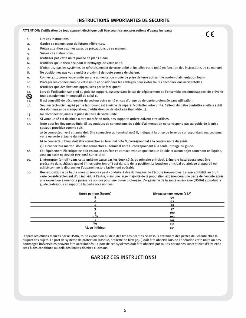
20. Uneexpositionàdehautsniveauxsonorespeutconduireàdesdommagesdel’écouteirréversibles.Lasusceptibilitéaubruitvarieconsidérablementd’unindividuàl’autre,maisunelargemajoritédelapopulationexpérienceraunepertedel’écouteaprèsuneexpositionàunefortepuissancesonorepouruneduréeprolongée.L’organismedelasantéaméricaine(OSHA)aproduitleguideci-dessousenrapportàlaperteoccasionnée:
Durée par Jour (heures) Niveau sonore moyen (dBA) 8 90 6 92 4 95 3 97 2 100 1 1⁄2 102 1 105 1⁄2 110 1⁄4 ou inférieur 115
D’aprèslesétudesmenéesparleOSHA,touteexpositionaudelàdeslimitesdécritesce-dessusentraineradespertesdel’écoutechezlaplupartdessujets.Leportdesystèmedeprotection(casque,oreilettedefiltrage,…)doitêtreobservélorsdel’opérationcetteunitéoudesdommagesirréversiblespeuventêtreoccasionnés.Leportdecessystèmesdoitêtreobservépartoutespersonnessusceptiblesd’êtreexpo-séesàdesconditionsaudelàdeslimitesdécritesci-dessus.
GARDEZ CES INSTRUCTIONS!
�
6
�
INSTRUCCIONES IMPORTANTES PARA SU SEGURIDAD
CUIDADO: Cuando use productos electrónicos, debe tomar precauciones básicas, incluyendo las siguientes:
1. Leaestasinstrucciones.
2. Guardeestasinstrucciones.
3. Hagacasodetodoslosconsejos.
4. Sigatodaslasinstrucciones.
5. Nousaresteaparatocercadelagua.
6. Limpiarsolamenteconunatelaseca.
7. Nobloquearningunadelassalidasdeventilación.Instalardeacuerdoalasinstruccionesdelfabricante.
8. Noinstalarcercadeningunafuentedecalorcomoradiadores,estufas,hornosuotrosaparatos(incluyendoamplificadores)queproduzcancalor.
9. Noretirelapatillaprotectoradelenchufepolarizadoodetipo“aTierra”.Unenchufepolarizadotienedospuntas,unadeellasmásanchaquelaotra.Unenchufedetipo“aTierra”tienedospuntasyunatercera“aTierra”.Lapuntaancha(latercera)seproporcionaparasuseguridad.Sielenchufeproporcionadonoencajaensuenchufedered,consulteaunelectricistaparaquereemplazesuenchufeobsoleto.
10. Protejaelcabledealimentaciónparaquenoseapisadoopinchado,particularmenteenlosenchufes,huecos,ylospuntosquesalendelaparato.
11. Usarsolamenteañadidos/accesoriosproporcionadosporelfabricante.
12. Usarsolamenteuncarro,pie,trípode,osoporteespecificadoporelfabricante,ovendidojuntoalaparato.Cuandoseuseuncarro,tengacuidadoalmoverelconjuntocarro/aparatoparaevitarquesedañeenunvuelco.Nosuspendaestacajadeningunamanera.
13. Desenchufeesteaparatodurantetormentasocuandonoseausadodurantelargosperiodosdetiempo.
14. Paracualquierreparación,acudaapersonaldeserviciocualificado.Serequierenreparacionescuandoelaparatohasidodañadodealgunamanera,comocuandoelcabledealimentaciónoelenchufesehandañado,algúnlíquidohasidoderramadooalgúnobjetohacaídodentrodelaparato,elaparatohasidoexpuestoalalluviaolahumedad,nofuncionademaneranormal,ohasufridounacaída.
15. NuncaretirelapatilladeTierra.Escríbanosparaobtenernuestrofolletogratuito“ShockHazardandGrounding”(“PeligrodeElectrocuciónyTomaaTierra”).Conecteelaparatosóloaunafuentedealimentacióndeltipomarcadoalladodelcabledealimentación.
16.Siesteproductovaaserenracadoconmásequipo,usealgúntipodeapoyotrasero.
17. NotaparaelReinoUnidosolamente:Siloscoloresdeloscablesenelenchufeprincipaldeestaunidadnocorrespondenconlosterminalesensuenchufe‚procedadelasiguientemanera:
a)ElcabledecolorverdeyazuldebeserconectadoalterminalqueestámarcadoconlaletraE‚elsímbolodeTierra(earth)‚coloreadoenverdeoenverdeyamarillo.
b)ElcablecoloreadoenazuldebeserconectadoalterminalqueestámarcadoconlaletraNoelcolornegro.
c)ElcablecoloreadoenmarróndebeserconectadoalterminalqueestámarcadoconlaletraLoelcolorrojo.
18.Esteaparatoeléctriconodebesersometidoaningúntipodegoteoosalpicaduraysedebetenercuidadoparanoponerobjetosquecontenganlíquidos,comovasos,sobreelaparato.
19. Elinterruptordeen/lejosenestaunidadnorompeambosladosdelaredprimaria.Laenergíapeligrosapuedeserpresentedentrodelchasiscuandoelinterruptordeen/lejosestáeneldelaposición.Eltapóndelaredoelacopladordelaparatosonutilizadoscomoeldesconectadispositivo,eldesconectadispositivosequedaráfácilmenteoperable.
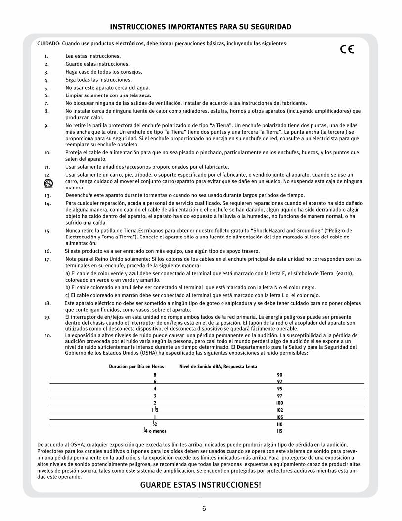
20. Laexposiciónaaltosnivelesderuidopuedecausarunapérdidapermanenteenlaaudición.Lasusceptibilidadalapérdidadeaudiciónprovocadaporelruidovaríasegúnlapersona,perocasitodoelmundoperderáalgodeaudiciónsiseexponeaunnivelderuidosuficientemanteintensoduranteuntiempodeterminado.ElDepartamentoparalaSaludyparalaSeguridaddelGobiernodelosEstadosUnidos(OSHA)haespecificadolassiguientesexposicionesalruidopermisibles:
Duración por Día en Horas Nivel de Sonido dBA, Respuesta Lenta
8 90 6 92 4 95 3 97 2 100 1 1⁄2 102 1 105 1⁄2 110 1⁄4 o menos 115
DeacuerdoalOSHA,cualquierexposiciónqueexcedaloslímitesarribaindicadospuedeproduciralgúntipodepérdidaenlaaudición.Protectoresparaloscanalesauditivosotaponesparalosoídosdebenserusadoscuandoseopereconestesistemadesonidoparapreve-nirunapérdidapermanenteenlaaudición,silaexposiciónexcedeloslímitesindicadosmásarriba.Paraprotegersedeunaexposiciónaaltosnivelesdesonidopotencialmentepeligrosa,serecomiendaquetodaslaspersonasexpuestasaequipamientocapazdeproduciraltosnivelesdepresiónsonora,talescomoestesistemadeamplificación,seencuentrenprotegidasporprotectoresauditivosmientrasestauni-dadestéoperando.
GUARDE ESTAS INSTRUCCIONES!
�

7
Butcher™ Guitar AmplifierThis newest Peavey guitar amplifier harkens back to the tones of classic rock while offering unique modern features. The Butcher is a two-channel amplifier with five 12AX7 preamp tubes and four EL34 power amp tubes. Both the Clean and Crunch channels feature independent three-band EQ, plus channel volume and preamp gain controls so guitarists can adjust the interplay between the preamp and power amp on each channel for an array of gain possibilities. Both channels include a separate, footswitchable gain boost, while the Crunch channel also has a 12-way Punch selector that adjusts the low-end attack of the amplifier—a handy feature that helps match the head to various playing styles at different levels of gain. The master section widens the range of possibilities with two footswitchable master volumes, so players can set one as a default and use the second as a solo boost and a Presence control that boosts the extreme high frequencies, giving the amp extra cut. On the rear panel, the built-in Peavey MSDI™ microphone-simulated XLR direct interface eliminates the need for miking by allowing users to send the amp's signal directly to a recording device or mixing console. Additional controls include an active effects loop with send and return level control, an impedance selector and a half-power switch, allowing you to rock the Butcher in either 50-watt or 100-watt mode.
Features:
• Two channels; Clean and Crunch
• 4xEL34 100W power section & 5x12AX7 preamp tubes
• Separate three band EQ on each channel
• Global presence control
• Two Master Volume controls for additional boost capabilities
• 12-way ‘punch' control on channel 2
• Pre-Gain boost switch on both channels
• Built in MSDI microphone simulated direct XLR output
• Active effects loop with send and return level
• Impedance selector
• Half Power switch
• MIDI control capability
• Included footswitch controls channel, boosts, loop and master volume switching
ENGLISH
VENTILATION: For proper ventilation, allow 12" clearance from the nearest combustible surface.
All vents should have a minimum of 2" of free air space so air can flow thru the unit freely for proper cooling.
8
Front Panel
111 2 4 5 6 7 8 9 12 13 14 15 16 17 18 19 20 21 223 10
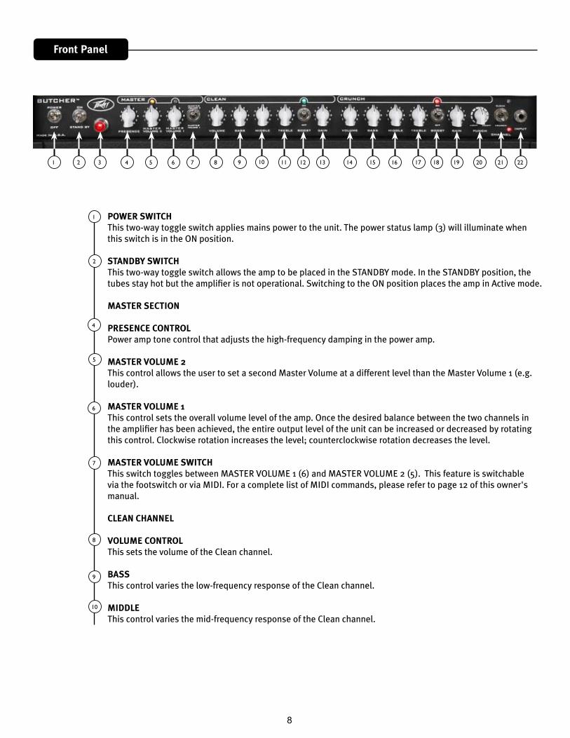
POWER SWITCHThis two-way toggle switch applies mains power to the unit. The power status lamp (3) will illuminate when this switch is in the ON position.
STANDBY SWITCHThis two-way toggle switch allows the amp to be placed in the STANDBY mode. In the STANDBY position, the tubes stay hot but the amplifier is not operational. Switching to the ON position places the amp in Active mode.
MASTER SECTION
PRESENCE CONTROLPower amp tone control that adjusts the high-frequency damping in the power amp.
MASTER VOLUME 2This control allows the user to set a second Master Volume at a different level than the Master Volume 1 (e.g. louder).
MASTER VOLUME 1This control sets the overall volume level of the amp. Once the desired balance between the two channels in the amplifier has been achieved, the entire output level of the unit can be increased or decreased by rotating this control. Clockwise rotation increases the level; counterclockwise rotation decreases the level.
MASTER VOLUME SWITCHThis switch toggles between MASTER VOLUME 1 (6) and MASTER VOLUME 2 (5). This feature is switchable via the footswitch or via MIDI. For a complete list of MIDI commands, please refer to page 12 of this owner's manual.
CLEAN CHANNEL
VOLUME CONTROLThis sets the volume of the Clean channel.
BASSThis control varies the low-frequency response of the Clean channel.
MIDDLEThis control varies the mid-frequency response of the Clean channel.
1
2
4
5
6
7
8
9
10
9
TREBLEThis control varies the high-frequency response of the Clean channel.
CHANNEL BOOSTThis switch activates a preamp boost in the Clean channel for a pronounced overdrive. This feature is swit-chable via the footswitch or via MIDI. For a complete list of MIDI commands, please refer to page 12 of this owner's manual.
CHANNEL GAINThis control controls the input volume level of the Clean channel. Rotating this control clockwise will increase the amount of preamp distortion and sustain.
CRUNCH CHANNEL
VOLUME CONTROLThis sets the volume for the Crunch channel.
BASSThis control varies the low-frequency response of the Crunch channel.
MIDDLEThis control varies the mid-frequency response of the Crunch channel.
TREBLEThis control varies the high-frequency response of the Crunch channel.
CHANNEL BOOSTThis switch activates a preamp boost in the Crunch channel for more gain. This feature is switchable via the footswitch or via MIDI. For a complete list of MIDI commands, please refer to page 12 of this owner's manual.
GAINThis control adjusts the input volume level of the Crunch channel. Rotating this control clockwise will increase the amount of preamp distortion and sustain.
CRUNCH CHANNEL "PUNCH" CONTROLThis 12-way selector that adjusts the low-end attack of the amplifier—a handy feature that helps match the head to various playing styles.
CHANNEL SELECT SWITCHThis two-position toggle switch allows selection between the amplifier’s Clean and Crunch channels. LED il-lumination indicates which channel is active. Channel switching can also be accomplished by footswitch or via MIDI control.
INPUTThis 1/4" jack is designed to accommodate any guitar output signal.
12
13
14
15
16
17
18
19
20
21
22
11
10
1 102 3 4 5 6 7 8 9
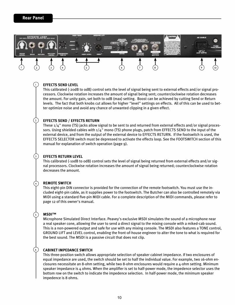
EFFECTS SEND LEVELThis calibrated (-20dB to 0dB) control sets the level of signal being sent to external effects and/or signal pro-cessors. Clockwise rotation increases the amount of signal being sent; counterclockwise rotation decreases the amount. For unity gain, set both to 0dB (max) setting. Boost can be achieved by cutting Send or Return levels. The fact that both knobs cut allows for higher "level" settings on effects. All of this can be used to bet-ter optimize noise and avoid any chance of unwanted clipping in a given effect.
EFFECTS SEND / EFFECTS RETURN These 1/4" mono (TS) jacks allow signal to be sent to and returned from external effects and/or signal proces-sors. Using shielded cables with 1/4" mono (TS) phone plugs, patch from EFFECTS SEND to the input of the external device, and from the output of the external device to EFFECTS RETURN. If the footswitch is used, the EFFECTS SELECTOR switch must be depressed to activate the effects loop. See the FOOTSWITCH section of this manual for explanation of switch operation (page 9).
EFFECTS RETURN LEVELThis calibrated (-10dB to 0dB) control sets the level of signal being returned from external effects and/or sig-nal processors. Clockwise rotation increases the amount of signal being returned; counterclockwise rotation decreases the amount.
REMOTE SWITCHThis eight-pin DIN connector is provided for the connection of the remote footswitch. You must use the in-cluded eight-pin cable, as it supplies power to the footswitch. The Butcher can also be controlled remotely via MIDI using a standard five-pin MIDI cable. For a complete description of the MIDI commands, please refer to page 12 of this owner's manual.
MSDI™Microphone Simulated Direct Interface. Peavey's exclusive MSDI simulates the sound of a microphone near a real speaker cone, allowing the user to send a direct signal to the mixing console with a miked-cab sound. This is a non-powered output and safe for use with any mixing console. The MSDI also features a TONE control, GROUND LIFT and LEVEL control, enabling the front-of-house engineer to alter the tone to what is required for the best sound. The MSDI is a passive circuit that does not clip.
CABINET IMPEDANCE SWITCHThis three-position switch allows appropriate selection of speaker cabinet impedance. If two enclosures of equal impedance are used, the switch should be set to half the individual value. For example, two 16-ohm en-closures necessitate an 8-ohm setting, while two 8-ohm enclosures would require a 4-ohm setting. Minimum speaker impedance is 4 ohms. When the amplifier is set to half-power mode, the impedence selector uses the bottom row on the switch to indicate the impedence selection. In half-power mode, the minimum speaker impedence is 8 ohms.
1
2
3
4
5
6
Rear Panel
11
SPEAKER OUTPUTSThese paralleled 1/4" mono (TS) jacks are provided for the connection of speaker enclosure(s). Minimum speaker impedance is 4 ohms. The CABINET IMPEDANCE SWITCH (7) should be set to match the load of the speaker cabinet(s).
HALF POWER SWITCHThe Butcher is equipped with a half-power switch that reduces the maximum output power from 100 watts to 50 watts. 50-watt amplifiers have a different character than 100 watt amplifiers, overdriving more quickly and at slightly lower volumes. This switch is available for you to determine your own personal preferences and can be a versatile tool in the studio as well. The CABINET IMPEDANCE SWITCH (7) should be set to match the load of the speaker cabinet(s), as the settings will be different for half-power mode.
IEC MAINS CONNECTORThis is a standard IEC power connector. An AC mains cord having the appropriate AC plug and ratings for the in-tended operating voltage is included in the carton. The mains cord should be connected to the amplifier before connecting to a suitable AC outlet.
U.S DOMESTIC AC MAINS CORDThe mains cord supplied with the unit is a heavy-duty, 3-conductor type with a conventional 120 VAC plug with ground pin. If the outlet used does not have a ground pin, a suitable grounding adapter should be used, and the third wire should be grounded properly.
Never break off the ground pin on any equipment. It is provided for your safety.
NOTE: FOR UK ONLYIf the colors of the wires in the mains lead of this unit do not correspond with the colored markings identifying the terminals in your plug, proceed as follows: (1) The wire that is colored green and yellow must be connected to the terminal that is marked by the letter E, the Earth symbol, colored green, or colored green and yellow. (2) The wire that is colored blue must be connected to the terminal that is marked with the letter N or the color black. (3) The wire that is colored brown must be connected to the terminal that is marked with the letter L or the color red.
FUSE A fuse is located within the cap of the fuse holder. This fuse must be replaced with one of the same type and value to avoid damaging the amplifier and voiding the warranty. If the amp repeatedly blows the fuse, it should be taken to a qualified service center for repair.
WARNING: THE FUSE SHOULD ONLY BE REPLACED AFTER THE POWER CORD HAS BEEN DISCONNECTED.
7
10
8
9
12
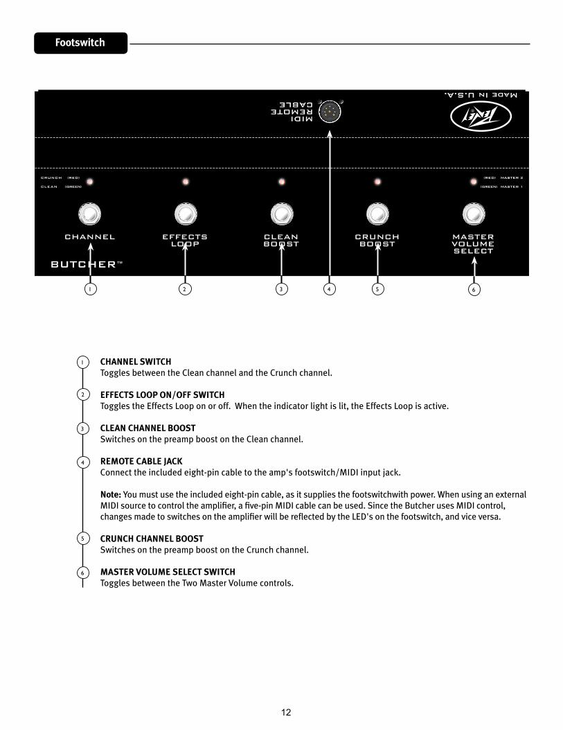
Footswitch
CHANNEL SWITCHToggles between the Clean channel and the Crunch channel.
EFFECTS LOOP ON/OFF SWITCHToggles the Effects Loop on or off. When the indicator light is lit, the Effects Loop is active. CLEAN CHANNEL BOOSTSwitches on the preamp boost on the Clean channel.
REMOTE CABLE JACKConnect the included eight-pin cable to the amp's footswitch/MIDI input jack.
Note: You must use the included eight-pin cable, as it supplies the footswitchwith power. When using an external MIDI source to control the amplifier, a five-pin MIDI cable can be used. Since the Butcher uses MIDI control, changes made to switches on the amplifier will be reflected by the LED's on the footswitch, and vice versa.
CRUNCH CHANNEL BOOSTSwitches on the preamp boost on the Crunch channel.
MASTER VOLUME SELECT SWITCHToggles between the Two Master Volume controls.
1
2
3
4
5
6
1 2 3 4 5 6
13
Specifications
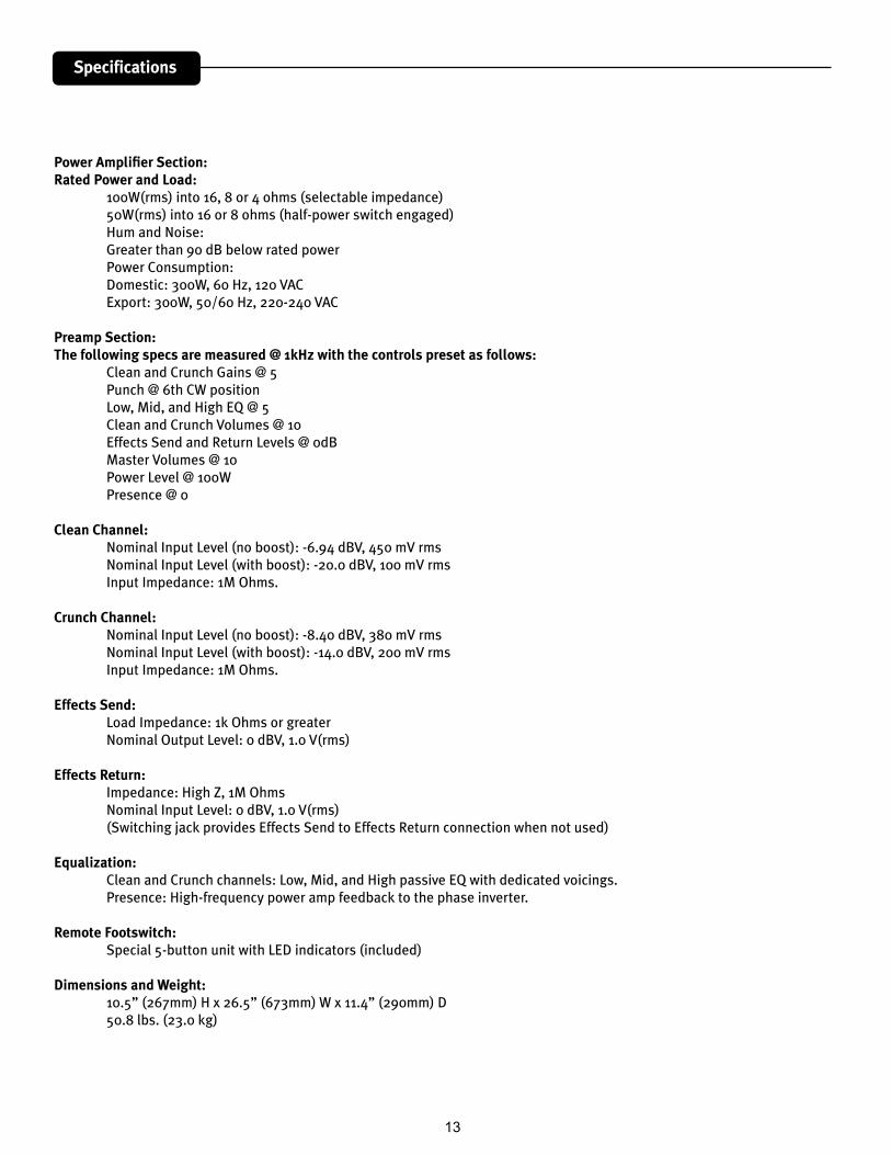
Power Amplifier Section:Rated Power and Load: 100W(rms) into 16, 8 or 4 ohms (selectable impedance) 50W(rms) into 16 or 8 ohms (half-power switch engaged) Hum and Noise: Greater than 90 dB below rated power Power Consumption: Domestic: 300W, 60 Hz, 120 VAC Export: 300W, 50/60 Hz, 220-240 VAC
Preamp Section:The following specs are measured @ 1kHz with the controls preset as follows: Clean and Crunch Gains @ 5 Punch @ 6th CW position Low, Mid, and High EQ @ 5 Clean and Crunch Volumes @ 10 Effects Send and Return Levels @ 0dB Master Volumes @ 10 Power Level @ 100W Presence @ 0
Clean Channel: Nominal Input Level (no boost): -6.94 dBV, 450 mV rms Nominal Input Level (with boost): -20.0 dBV, 100 mV rms Input Impedance: 1M Ohms.
Crunch Channel: Nominal Input Level (no boost): -8.40 dBV, 380 mV rms Nominal Input Level (with boost): -14.0 dBV, 200 mV rms Input Impedance: 1M Ohms.
Effects Send: Load Impedance: 1k Ohms or greater Nominal Output Level: 0 dBV, 1.0 V(rms)
Effects Return: Impedance: High Z, 1M Ohms Nominal Input Level: 0 dBV, 1.0 V(rms) (Switching jack provides Effects Send to Effects Return connection when not used)
Equalization: Clean and Crunch channels: Low, Mid, and High passive EQ with dedicated voicings. Presence: High-frequency power amp feedback to the phase inverter.
Remote Footswitch: Special 5-button unit with LED indicators (included)
Dimensions and Weight: 10.5” (267mm) H x 26.5” (673mm) W x 11.4” (290mm) D 50.8 lbs. (23.0 kg)
14
SP
PUN
CH
EQ
LOM
IDH
I
EQ
LOM
IDH
I
LEVE
L
EQ B
UFF
ER
(BO
OST
)
8 O
HM
S
4 O
HM
S+H
V
IMPE
DAN
CE
SWIT
CH
MSD
I
FILT
ERG
RO
UN
D
LIFT
SPEA
KER
OU
TPU
TS16
OH
MS
V6 &
V8
V7 &
V9
POW
ER A
MP
(4 x
EL3
4)
V5
V1A
V1B
V2A
CR
UN
CH
BO
OST
V2B
PHAS
E IN
VER
TER
1 &
2VO
LUM
E
CLE
AN B
OO
ST
V3A
V4A
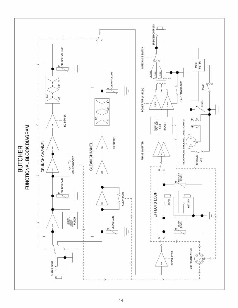
BUTC
HER
FUN
CTI
ON
AL B
LOC
K D
IAG
RAM
CR
UN
CH
CH
ANN
EL
V4B
GU
ITAR
INPU
T
CLE
AN G
AIN
CR
UN
CH
GAI
NC
RU
NC
H V
OLU
ME
CLE
AN V
OLU
ME
EQ B
UFF
ER
LOO
P BU
FFER
CLE
AN C
HAN
NEL
EFFE
CTS
LO
OP
RET
UR
N
SEN
D
SEN
DLE
VEL
RET
UR
N
MIC
RO
PHO
NE
SIM
ULA
TED
DIR
ECT
OU
TPU
T
MID
I / F
OO
TSW
ITC
H
V3B
LEVE
LTO
NE
MAS
TER
HAL
F PO
WER
(50W
)
2
3
1
15
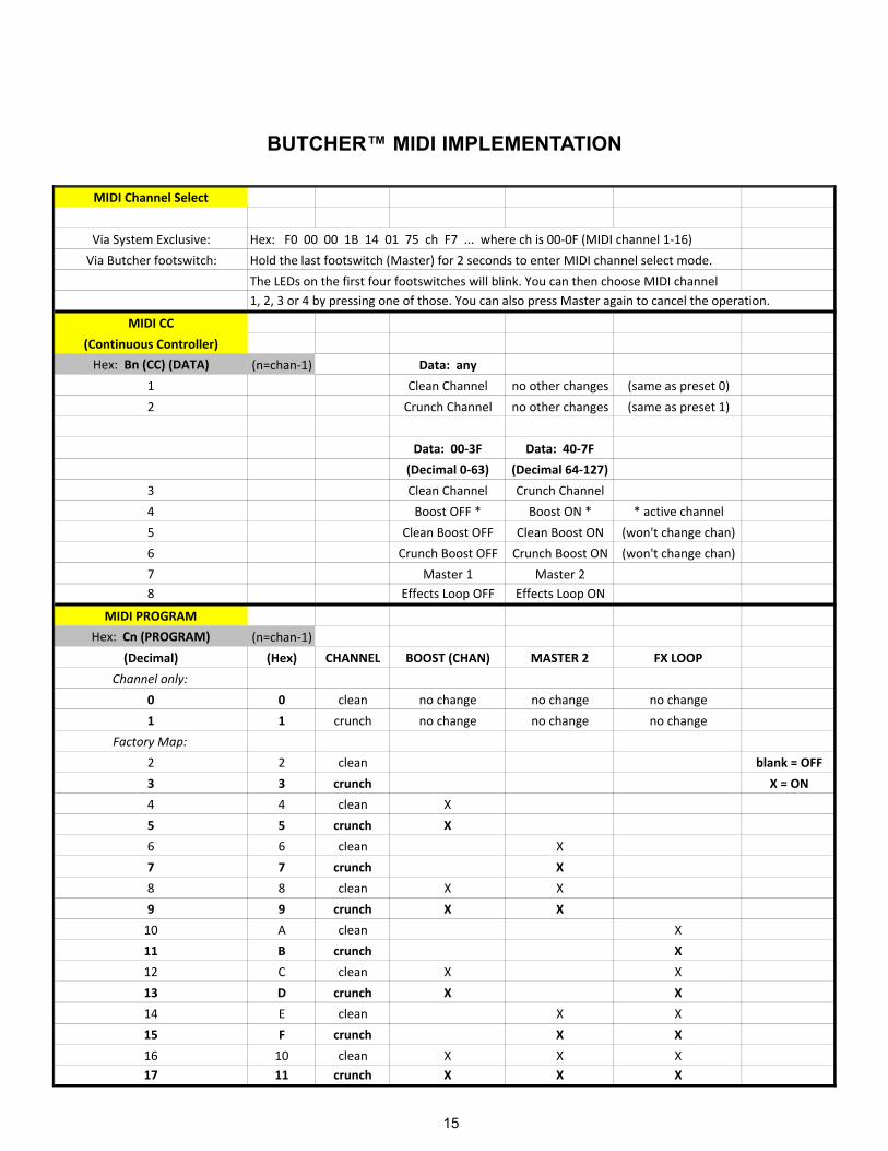
BUTCHER™ MIDI IMPLEMENTATION
MIDI Channel Select
Via System Exclusive: Hex: F0 00 00 1B 14 01 75 ch F7 ... where ch is 00‐0F (MIDI channel 1‐16)
Via Butcher footswitch: Hold the last footswitch (Master) for 2 seconds to enter MIDI channel select mode.
The LEDs on the first four footswitches will blink. You can then choose MIDI channel 1, 2, 3 or 4 by pressing one of those. You can also press Master again to cancel the operation.
MIDI CC
(Continuous Controller)
Hex: Bn (CC) (DATA) (n=chan‐1) Data: any
1 Clean Channel no other changes (same as preset 0)
2 Crunch Channel no other changes (same as preset 1)
Data: 00‐3F Data: 40‐7F
(Decimal 0‐63) (Decimal 64‐127)
3 Clean Channel Crunch Channel
4 Boost OFF * Boost ON * * active channel
5 Clean Boost OFF Clean Boost ON (won't change chan)
6 Crunch Boost OFF Crunch Boost ON (won't change chan)
7 Master 1 Master 28 Effects Loop OFF Effects Loop ON
MIDI PROGRAM
Hex: Cn (PROGRAM) (n=chan‐1)
(Decimal) (Hex) CHANNEL BOOST (CHAN) MASTER 2 FX LOOP
Channel only:
0 0 clean no change no change no change
1 1 crunch no change no change no change
Factory Map:
2 2 clean blank = OFF
3 3 crunch X = ON
4 4 clean X
5 5 crunch X
6 6 clean X
7 7 crunch X
8 8 clean X X
9 9 crunch X X
10 A clean X
11 B crunch X
12 C clean X X
13 D crunch X X
14 E clean X X
15 F crunch X X
16 10 clean X X X17 11 crunch X X X

PEAVEY ELECTRONICS CORPORATION LIMITED WARRANTYEffective Date: 03/04/2010
What This Warranty CoversYour Peavey Warranty covers defects in material and workmanship in Peavey products purchased and serviced in the U.S.A. and Canada.
What This Warranty Does Not CoverThe Warranty does not cover: (1) damage caused by accident, misuse, abuse, improper installation or operation, rental, product modification or neglect; (2) damage occurring during shipment; (3) damage caused by repair or service performed by persons not authorized by Peavey; (4) products on which the serial number has been altered, defaced or removed; (5) products not purchased from an Authorized Peavey Dealer.
Who This Warranty ProtectsThis Warranty protects only the original purchaser of the product.
How Long This Warranty LastsThe Warranty begins on the date of purchase by the original retail purchaser. The duration of the Warranty is as follows:
Product Category Duration
Guitars/Basses, Amplifiers, Preamplifiers, Mixers, Electronic Crossovers and Equalizers 2 years *(+ 3 years)
Drums 2 years *(+ 1 year)
Enclosures 3 years *(+ 2 years)
Digital Effect Devices and Keyboards and MIDI Controllers 1 years *(+ 1 year)
Microphones 2 years
Speaker Components 1 year (incl. Speakers, Baskets, Drivers, Diaphragm Replacement Kits and Passive Crossovers)
Tubes and Meters 90 Days
Cables Limited Lifetime
Rockmaster Series, Strum’n Fun, Vectra, Rotor, OCC Stage pack, 1 year GT & BT Series amps, Retro Fire, Metal Maker and Iron Wing
[* Denotes additional Warranty period applicable if optional Warranty Registration Card is completed and returned to Peavey by original retail purchaser within 90 days of purchase.]
What Peavey Will DoWe will repair or replace (at Peavey’s discretion) products covered by Warranty at no charge for labor or materials. If the product or component must be shipped to Peavey for Warranty service, the consumer must pay initial shipping charges. If the repairs are covered by Warranty, Peavey will pay the return shipping charges.
How To Get Warranty Service(1) Take the defective item and your sales receipt or other proof of date of purchase to your Authorized Peavey Dealer or Authorized Peavey Service Center.OR(2) Ship the defective item, prepaid, to Peavey Electronics Corporation, International Service Center, 412 Highway 11 & 80 East, Meridian, MS 39301. Include a detailed description of the problem, together with a copy of your sales receipt or other proof of date of purchase as evidence of Warranty coverage. Also provide a complete return address.
Limitation of Implied WarrantiesANY IMPLIED WARRANTIES, INCLUDING WARRANTIES OF MERCHANTABILITY AND FITNESS FOR A PARTICULAR PURPOSE, ARE LIMITED IN DURATION TO THE LENGTH OF THIS WARRANTY.Some states do not allow limitations on how long an implied Warranty lasts, so the above limitation may not apply to you.
Exclusions of DamagesPEAVEY’S LIABILITY FOR ANY DEFECTIVE PRODUCT IS LIMITED TO THE REPAIR OR REPLACEMENT OF THE PRODUCT, AT PEAVEY’S OPTION. IF WE ELECT TO REPLACE THE PRODUCT, THE REPLACEMENT MAY BE A RECONDITIONED UNIT. PEAVEY SHALL NOT BE LIABLE FOR DAMAGES BASED ON INCONVENIENCE, LOSS OF USE, LOST PROFITS, LOST SAVINGS, DAMAGE TO ANY OTHER EQUIPMENT OR OTHER ITEMS AT THE SITE OF USE, OR ANY OTHER DAMAGES WHETHER INCIDENTAL, CONSEQUENTIAL OR OTHERWISE, EVEN IF PEAVEY HAS BEEN ADVISED OF THE POSSIBILITY OF SUCH DAMAGES.Some states do not allow the exclusion or limitation of incidental or consequential damages, so the above limitation may not apply to you.
This Warranty gives you specific legal rights, and you may also have other rights which vary from state to state.
If you have any questions about this Warranty or services received or if you need assistance in locating an Authorized Service Center, please contact the Peavey International Service Center at (601) 483-5365.
Features and specifications are subject to change without notice.
Logo referenced in Directive 2002/96/EC Annex IV(OJ(L)37/38,13.02.03 and defined in EN 50419: 2005The bar is the symbol for marking of new waste and
is applied only to equipment manufactured after13 August 2005

Logo referenced in Directive 2002/96/EC Annex IV(OJ(L)37/38,13.02.03 and defined in EN 50419: 2005The bar is the symbol for marking of new waste and
is applied only to equipment manufactured after13 August 2005

FROM:Place
PostageHere
Peavey Electronics CorporationAttn: Warranty Department
P.O. Box 5108Meridian, Ms 39302-5108

NOTES

Features and specifications subject to change without notice.
Peavey Electronics Corporation • 5022 Hartley Peavey Drive • Meridian • MS • 39305 (601) 483-5365 • FAX (601) 486-1278 • www.peavey.com • ©2010