bus physics & wiring date 09/06/00, page 1 bus physics & wiring s profibus...
TRANSCRIPT

Bus Physics & WiringDate 09/06/00, Page 1
Bus Physics & Wiring
s
PROFIBUS wiring/installation can be done with:
Copper
Fiber optic
Infrared & RF components

Bus Physics & WiringDate 09/06/00, Page 2
Bus Physics & Wiring
s
PROFIBUS is based on RS485...
Network consists of RS485 segments
Proper installation
required

Bus Physics & WiringDate 09/06/00, Page 3
Bus Physics & Wiring
s
PROFIBUS Segments
Connected via repeaters
New segment when maximum length or
number of devices per segment is reached
Bus Physics & WiringDate 09/06/00, Page 4
Bus Physics & Wiring
s
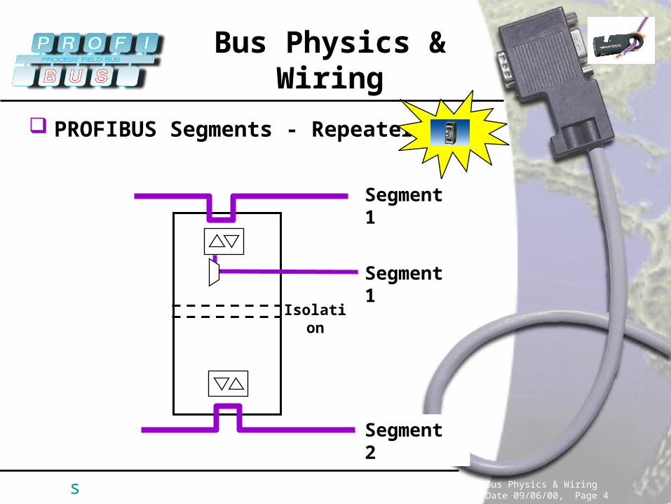
PROFIBUS Segments - Repeater
Segment 2
Segment 1
Isolation
Segment 1
Bus Physics & WiringDate 09/06/00, Page 5
Bus Physics & Wiring
s
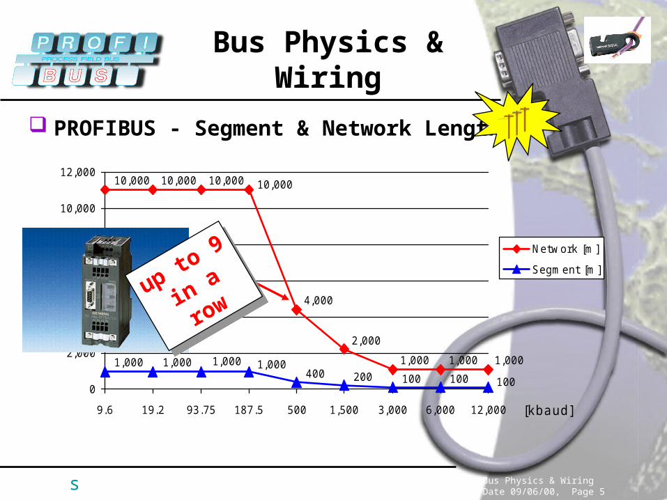
PROFIBUS - Segment & Network Length
1001001002004001,0001,0001,0001,000
4,000
2,000
10,000
1,0001,0001,000
10,00010,00010,000
0
2,000
4,000
6,000
8,000
10,000
12,000
9.6 19.2 93.75 187.5 500 1,500 3,000 6,000 12,000 [kbaud]
Network [m]
Segment [m]
up to 9
in a rowup to
9
in a row

Bus Physics & WiringDate 09/06/00, Page 6
Bus Physics & Wiring
s
PROFIBUS Segments - Nodes/Devices
Up to 126 addressable nodes per network
Up to 32 devices per segment
RepeaterPROFIBUSNodes (e.g. I/O)
Optical LinkModules(OLMs)
! No PROFIBUS Address !
! No PROFIBUS Address !
What counts as “device”?
Bus Physics & WiringDate 09/06/00, Page 7
Bus Physics & Wiring
s
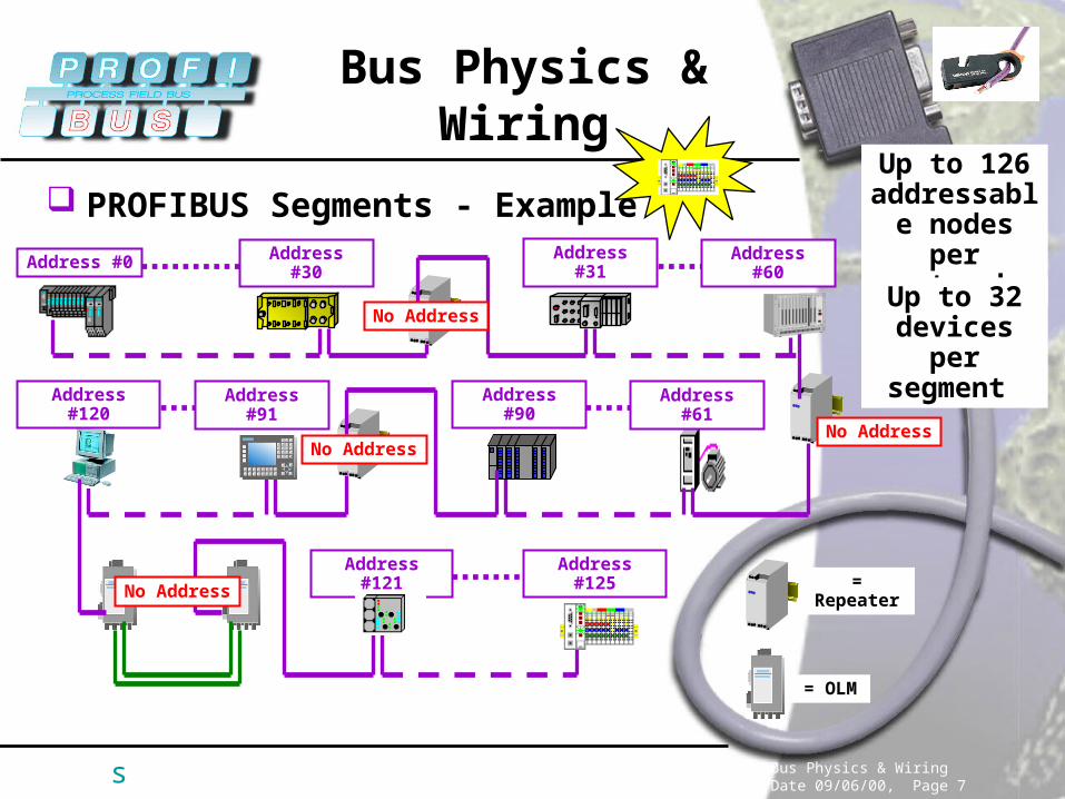
PROFIBUS Segments - Example
Address #0 Address #30 Address #31 Address #60
Address #90 Address #61Address #120 Address #91
Address #121 Address #125= Repeater
= OLM
No Address
No AddressNo Address
No Address
Up to 126 addressable nodes per network
Up to 32 devices per
segment

Bus Physics & WiringDate 09/06/00, Page 8
Bus Physics & Wiring
s
Installation
Shielding & Grounding
Drop Lines
Termination
Cable Distances

Bus Physics & WiringDate 09/06/00, Page 9
Bus Physics & Wiring
s
Installation - Shielding & Grounding
Improves EMC behavior
Provides a low impedance (short) return path for noise and current
Reduces the emission from the bus
!!!Shield is not always connected to
protective GND within the devices; therefore, make sure the cable shield will be connected to GND before it enters or
leaves the cabinet!!!
!!!Shield is not always connected to
protective GND within the devices; therefore, make sure the cable shield will be connected to GND before it enters or
leaves the cabinet!!!

Bus Physics & WiringDate 09/06/00, Page 10
Bus Physics & Wiring
s
Installation - Cable Distances
CableCategory
II
>= 20 cm
>= 10 cm >= 10 cm
>= 50 cm
>= 50 cm
>= 50 cm
CableCategory
I
CableCategory
III
CableCategory
IV
Bus Physics & WiringDate 09/06/00, Page 11
Bus Physics & Wiring
s
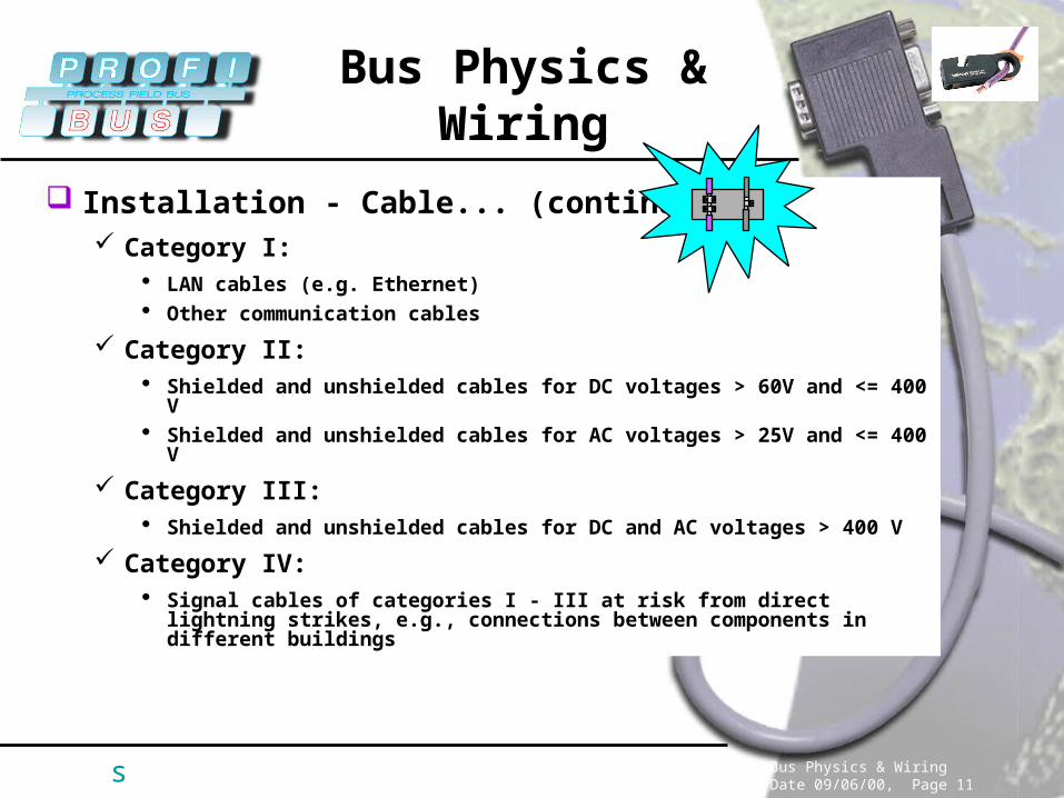
Installation - Cable... (continued) Category I:
LAN cables (e.g. Ethernet) Other communication cables
Category II: Shielded and unshielded cables for DC voltages > 60V and <= 400 V Shielded and unshielded cables for AC voltages > 25V and <= 400 V
Category III: Shielded and unshielded cables for DC and AC voltages > 400 V
Category IV: Signal cables of categories I - III at risk from direct lightning strikes,
e.g., connections between components in different buildings

Bus Physics & WiringDate 09/06/00, Page 12
Bus Physics & Wiring
s
Installation - T-Connections (Drop/Stub/Spur)
Every branch or drop directly from the cable
Stubs to devices cause reflections (additional capacitance)
Repeaters are not spur-lines
RS485
(A)
(B)
Internal to device
Between device and trunk line
DeviceRS485
Device
! Manufacturer !
! Manufacturer !

Bus Physics & WiringDate 09/06/00, Page 13
Bus Physics & Wiring
s
Installation - T-Connections (Drop/Stub/Spur)
100
0006.62033
500 500
0
50
100
150
200
250
300
350
400
450
500
550
600
9.6 19.2 93.75 187.5 500 1,500 3,000 6,000 12,000 [kbaud]
Allowed Length [m]
For Drops above
187.5kBaud:
use Bus Terminals or
RepeatersFor D
rops above
187.5kBaud:
use Bus Terminals or
Repeaters
Although stub lines can theoretically be tolerated at thelower baud rates, the recommendation is to avoid the use
of stub lines altogether.
Although stub lines can theoretically be tolerated at thelower baud rates, the recommendation is to avoid the use
of stub lines altogether.
Bus Physics & WiringDate 09/06/00, Page 14
Bus Physics & Wiring
s
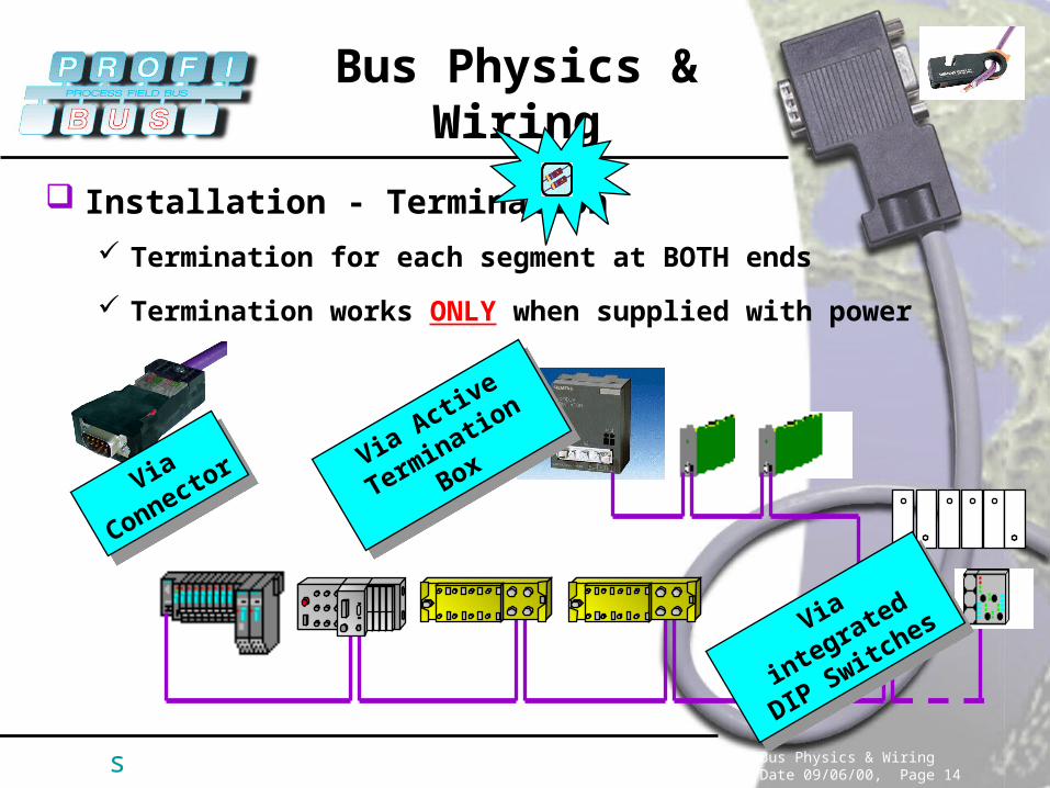
Installation - Termination
Termination for each segment at BOTH ends
Termination works ONLY when supplied with power
Via
ConnectorVia
Connector Via Active
Terminatio
n Box
Via Active
Terminatio
n Box
Via integrated
DIP Switches
Via integrated
DIP Switches

Bus Physics & WiringDate 09/06/00, Page 15
Bus Physics & Wiring
s
Installation - Termination: Example
OLM OLM OLM
Repeater

Bus Physics & WiringDate 09/06/00, Page 16
Bus Physics & Wiring
s
Wiring - Easy, when you use the right tools...

Bus Physics & WiringDate 09/06/00, Page 17
Bus Physics & Wiring
s
Wiring - Easy, when you use the right tools...
4x
3. Insert the end of the cable into the stripper using your left index finger as a limit stop to ensure the correct length is inserted.
1. How to hold the insulationstripper in your right hand.
2. Match up the cable end with the template so that your left index finger is against the end surface of the tool.
6. With the clamp still closed,pull the stripper off the end ofthe cable.
4. Clamp the cable firmly in the stripper.
5. Rotate the stripper aroundthe cable 4 times in thedirection of the arrow.

Bus Physics & WiringDate 09/06/00, Page 18
Bus Physics & Wiring
s
Wiring - Easy, when you use the right tools...
9. After removing the insulationfrom the cores, the cable canbe fitted into the PB connector.
7. The removed insulationremains in the stripper. Afterreleasing the clamp, theremnants can be removed.
8. Pull the protective foil off thecores.
green wire A
red wire B

Bus Physics & WiringDate 09/06/00, Page 19
Bus Physics & Wiring
s
Copper is not the End of the Road...
Plastic, PCF and glass fiber optic available
Plastic - 50m between 2 Optical Link Modules (OLM)
PCF - 300m between 2 OLMs
Glass - up to 15km between 2 OLMs
Connections via modules or integrated interface
When is Fiber Optic the Choice?
Noise immunity & independence from potential differences
Cover longer distances
Line, ring and star configuration possible
Media redundancy

Bus Physics & WiringDate 09/06/00, Page 20
Bus Physics & Wiring
s
Fiber Optic - Optical Link Modules (OLM)
OLM
PROFIBUS FO - Glass, PCF or Plastic

Bus Physics & WiringDate 09/06/00, Page 21
Bus Physics & Wiring
s
Fiber Optic - Integrated FO Interface
= Optical Bus Terminal (OBT)
PROFIBUS FO - PCF or Plastic
Bus Physics & WiringDate 09/06/00, Page 22
Bus Physics & Wiring
s
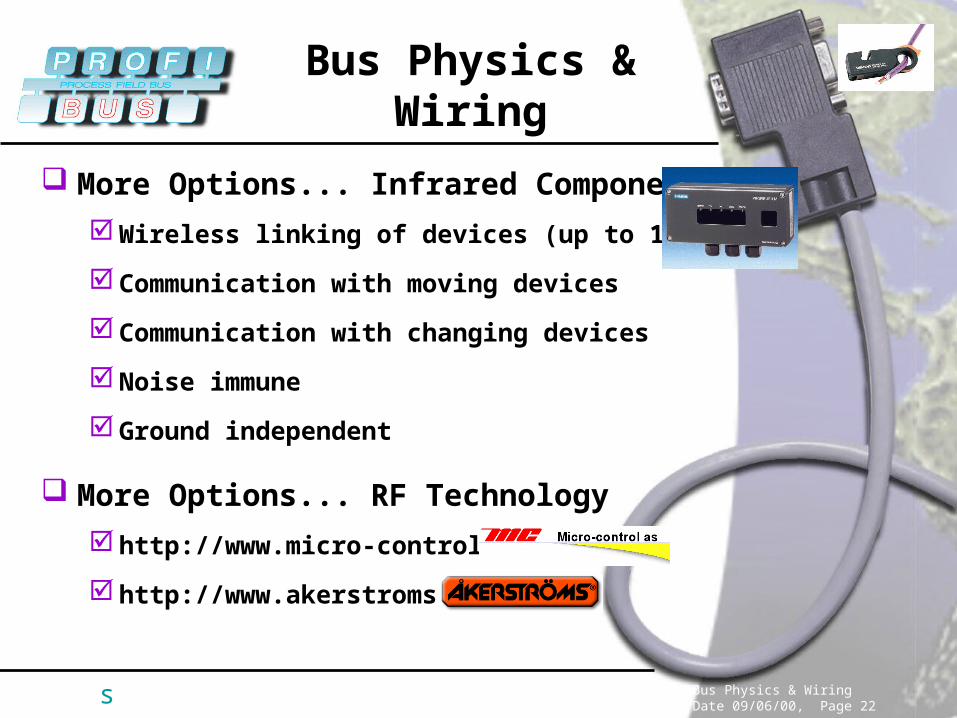
More Options... Infrared Components
Wireless linking of devices (up to 15m)
Communication with moving devices
Communication with changing devices
Noise immune
Ground independent
More Options... RF Technology
http://www.micro-control.no
http://www.akerstroms.no