bus differential relay using auxiliary summation ct’s 1 · pdf filebus differential...
TRANSCRIPT
Page 1
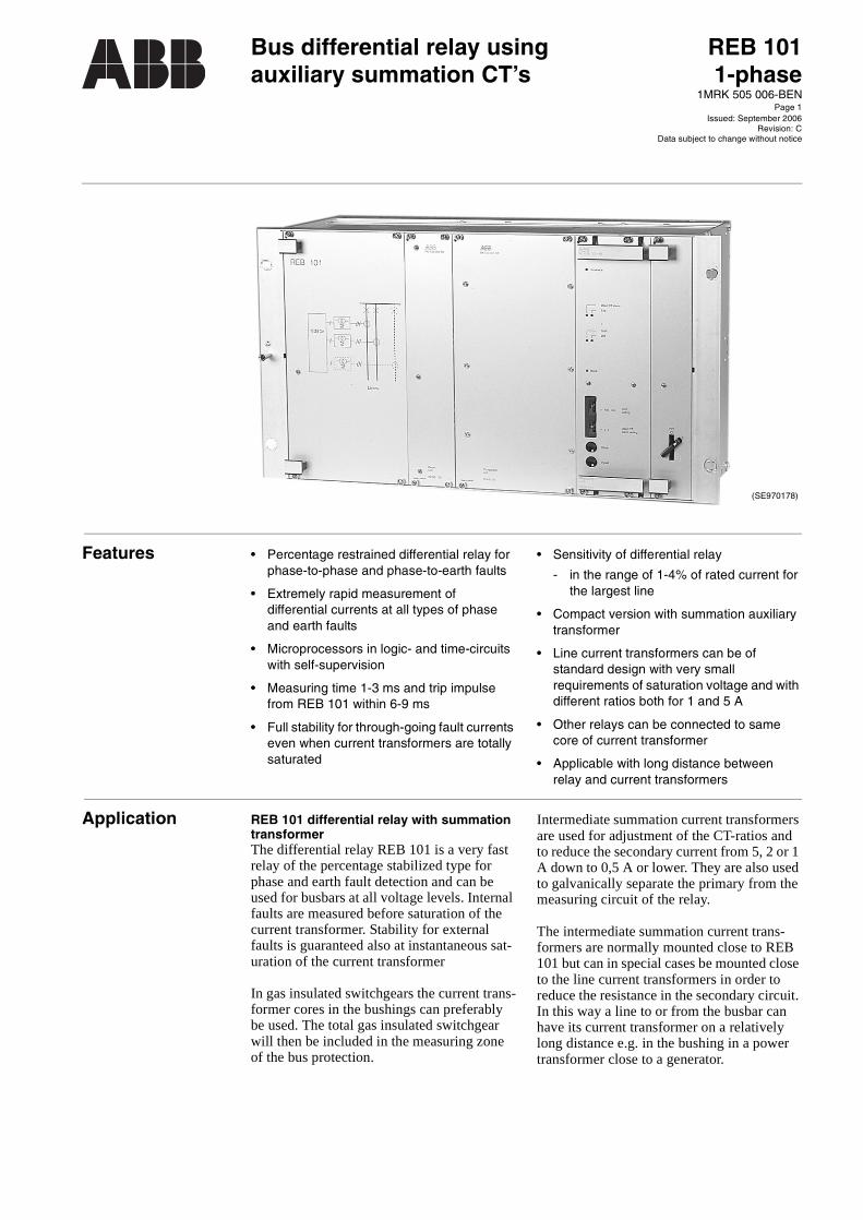
(SE970178)
Bus differential relay usingauxiliary summation CT’s
REB 1011-phase
1MRK 505 006-BEN
Issued: September 2006Revision: C
Data subject to change without notice
Features • Percentage restrained differential relay for phase-to-phase and phase-to-earth faults
• Extremely rapid measurement ofdifferential currents at all types of phase and earth faults
• Microprocessors in logic- and time-circuits with self-supervision
• Measuring time 1-3 ms and trip impulse from REB 101 within 6-9 ms
• Full stability for through-going fault currents even when current transformers are totally saturated
• Sensitivity of differential relay
- in the range of 1-4% of rated current for the largest line
• Compact version with summation auxiliary transformer
• Line current transformers can be ofstandard design with very small requirements of saturation voltage and with different ratios both for 1 and 5 A
• Other relays can be connected to same core of current transformer
• Applicable with long distance between relay and current transformers
Application REB 101 differential relay with summation transformerThe differential relay REB 101 is a very fast relay of the percentage stabilized type for phase and earth fault detection and can be used for busbars at all voltage levels. Internal faults are measured before saturation of the current transformer. Stability for external faults is guaranteed also at instantaneous sat-uration of the current transformer
In gas insulated switchgears the current trans-former cores in the bushings can preferably be used. The total gas insulated switchgear will then be included in the measuring zone of the bus protection.
Intermediate summation current transformers are used for adjustment of the CT-ratios and to reduce the secondary current from 5, 2 or 1 A down to 0,5 A or lower. They are also used to galvanically separate the primary from the measuring circuit of the relay.
The intermediate summation current trans-formers are normally mounted close to REB 101 but can in special cases be mounted close to the line current transformers in order to reduce the resistance in the secondary circuit. In this way a line to or from the busbar can have its current transformer on a relatively long distance e.g. in the bushing in a power transformer close to a generator.

Bus differential relay using auxiliary summation CT’s
REB 101 1-phase1MRK 505 006-BEN
Page 2
Application (cont’d)Application (cont’d) Busbar arrangementsThe arrangements of power system buses vary widely depending on the magnitude of the through going load current, the number of line circuits and the need for splitting up the station in several zones subsequent to an internal bus fault.
The normal rating of a bus conductor is from 1000-3000 A and a typical number of lines to a certain bus zone is 6-12 L. For the largest installations 2, 4 and 6 relay zones may be installed.
Single bus one-zoneThe most simple and reliable installation is the single bus one-zone arrangement (Fig. 1). In this case it can also be permitted that a bus section switch (S) is opened at certain times to split the bus in two parts. As long as there is no internal fault the REB 101 differential relay remains stable. This applies even when the two bus sections are working asynchro-nously, e.g. at different frequencies; however, when an internal fault occurs, both sections will always be tripped simultaneously. When the bus selection switch is open, the two sec-tions must then be supplied radially, i.e. inter-nal fault currents to one section must not pass through to the other section.
Fig. 1 Single-bus. one zone with bussection switch normally closed
Single bus two-zones with bus section switchWhen the bus section switch (A12) in Fig. 2 is kept open during longer periods of time, it may be an advantage to include two differen-tial relays. The two sections may then work independently and when a fault occurs only the affected section is tripped.
When the A12 switch is closed, all the input circuits will be connected to the DA1 relay and the DA2 relay is disconnected. The oper-
ating sensitivity is then determined only by the DA1 relay. If both relays should be kept in service at the same time the total relay operating current becomes twice as large.
The switching relay units are arranged to work in a special sequence so that the CT sec-ondary circuits never become open-circuited.
Fig. 2 Single-bus. one zone with bus section switch normally open
Double-bus with CT switchingOne of the most common arrangements is the double-bus, with one bus coupler and one cir-cuit-breaker per line (Fig. 3). When line L1, connected to the A-bus (L1:1 closed), is to be switched to the B-bus, the following sequence is use
1) The bus coupler circuit-breaker K:0 is closed.
2) The selector switch L1:2 is closed. Its cor-responding auxiliary contact in the CT sec-ondary is arranged to close earlier than the main (HV) contact.
3) Both selector switches (L1:1 and :2) are now closed and this situation activates a bus interconnection relay unit, which inter-connects the CT circuits of the A- and B-zones and disconnects the DB-relay.The operating sensitivity then becomes controlled by only one relay, instead of two relays in parallel. Also, the two trip circuits are interconnected so that both buses are tripped for a fault on one bus.
4) The selector switch L1:1 is then opened and the bus interconnection unit brings the DB-relay back into service and separates both the CT and the trip circuit intercon-nection.
(960
002
24)
(960
002
25)

Bus differential relay using auxiliary summation CT’s
REB 101 1-phase1MRK 505 006-BEN
Page 3
It should be noticed that during this switching operation the CT secondaries are never open-circuited so no dangerous voltages ever will occur; if a fault occurs, one or both buses will be tripped instantaneously. In the case of dou-ble-buses it is recommended that the main
bus coupler CT has two separate cores, one for each bus zone so as to avoid interference from one zone to the other. If only one core is available, its knee-point voltage should be higher than the knee-point voltage of the two auxiliary CT’s put together.
Fig. 3 Double-bus, two-zones with switching of CT secondary circuit.A bypass switch may be added.
The single-phase REB 101 bus differential relay including an auxiliary summation CT, which has a four-wire L1, L2, L3 - N input, and two-wire output, for every line. The pro-tection thus obtained operates for all types of
internal phase and earth faults. The operating sensitivity, with the SR-starting relay set at 0,1 A, varies in the range 9-36% of the largest line CT rating.
Fig. 4 For each line, one auxiliary summation CT is used
(96
000
226
)(9
6000
243
)

Bus differential relay using auxiliary summation CT’s
REB 101 1-phase1MRK 505 006-BEN
Page 4
Design REB 101 summation type differential relayThe REB 101 differential relay measuring circuit is provided in modern microprocessor technology, enhancing the functionality and including self-supervision for high availabil-ity.
SRThe start relay is used as current detector and is normally set at 0,1 A. It can also be set at a lower value when maximum sensitivity is required. When setting the thumb-wheel to 0, the pick-up will be approximately the same as the differential relay.
DRThe differential relay is selective and operates only for internal faults. The sensitivity is around 1-4% of the largest current trans-former.
The measuring elements of SR and DR oper-ates within 1-3 ms and tripping of the busbar is not initiated until both elements have oper-ated.
The stability (S) i.e. the relation between the differential current ID1 and the incoming cur-rent IT3 is applicable for external faults and is around 50%. At internal faults the relay has another characteristic with a larger operating area.
ARThe alarm relay operates for the differential current caused by an open CT-circuit and has a settable operating value. Five seconds after
operation of the AR-relay, the tripping circuit is opened and the differential circuit is short-circuited. This function is reset manually.
The total incoming current IT3 enters the relay at terminal K, and the total outgoing current leaves at terminal L. During normal service these currents are basically equal, and the different current is zero, or in practice less than 0,5 mA.
A restraint voltage US is obtained across the full stabilizing resistor RS, i.e. between the terminals K and L, and this voltage drives a current IR2 through the diode D2 and the resistor RD3, towards the output terminal L. The differential DR element is then securely restrained (blocked) and cannot operate.
When a differential (spill) current ID1 is pro-duced, this passes a variable resistor RD11, the primary winding of an auxiliary CT (TMD) and the starting relay SR, which is used for selecting a suitable level of primary operating current. On the secondary side of TMD, the differential current is passed through a full wave rectifier and the resistor RD3 across which is developed an operating voltage UD3.
A comparison may then be made, between the operating and restraint voltages, UD3 and US. The output from this comparator circuit is fed to the high speed polarized differential relay element (DR). When the operating volt-age is larger than the restraint voltage, the output current IR1 is regarded as positive and causes operation of the DR element.

Bus differential relay using auxiliary summation CT’s
REB 101 1-phase1MRK 505 006-BEN
Page 5
Fig. 5 Schematic diagram for a single-zone bus differential relay with feeders LA, LB and LX
IA2
LA
IA1
IA3 IB3
IB1
LB
IB2
URZ
IX1
LX
IX2
RZ1 RZ2IX3 TM2
SR
AR
ID1T
UD3
DR UR
D2
RS1
RS2
RD11
L
K
US
RD3
IT3 IR2
TMD
A-bus
N
IL
ID1
IR1
ID2
TMA
(97
0000
01)
AR Alarm relay
SR Start relay
DR Differential relay
US Stabilizing voltage
UD3 Operate voltage
IR1 Current through differential relay
IR2 Block current through diode D2
IT3 Total incoming current at terminal K
IL Current outgoing at terminal L
TMA Intermediate summation current transformer
TMD Ratio, nd = 10
n0 Total current transformer ratio= IA1/IA3 = IX1/IX3
RS,RD3
Resistance in stabilizing circuitDifferential circuit resistor
RD1 Resistance Rd3 recalculated to primary side of TMD
RT Total resistance in differential circuitRDT = RD1 + RD11

Bus differential relay using auxiliary summation CT’s
REB 101 1-phase1MRK 505 006-BEN
Page 6
Design (cont’d)Design (cont’d)
REB 101 differential relay with summation auxiliary transformer
RLDA 101 measuring unit
All settings and indications are positioned in RLDA 101. Settings are made with thumb-wheels and indications given by LEDs.
Indication is given with yellow LEDs for:
- Start relay
- Differential relay
- Open CT Alarm
Indication for tripping is given with red LED.
Indication for blocked relay is given with yellow LED.
The settings of start and alarm relays are easily accessible in the front. The start relay can be set between: 0-1,5 A and the alarm relay between 2 and 30 V.
REB 101 is equipped with self-supervision for:
- low dc/dc-supply
- microprocessor fault
Faults detected by the self-supervision, blocks the relay and gives indication in the front.
Fig. 6 RLDA 101 Measuring unit
REB 101
Basic unit max. 36 lines RK 638 002-AA
101 RXTP 18 Test unit
109 RXTP 18 Test unit
118 RXTP 18 Test unit
127 RLOE 100 Diode unit
137 RLHE 100 Comparator unit
162 RLDA 101 Measuring unit
177 RXTUG 21H Dc/dc converter
501 RXMD Block relay
509 RXME Trip relay
577 577 Switch
Made in Sweden
In service
TripOpen CT alarm
StartDiff
Block
Block
Reset
x
x
2V
100 mA Startsetting
alarm settingOpen CT
Indications
In service (green)
Open CT-circuit (yellow)Tripping (red)
Start relay (yellow)Differential relay (yellow)
Block (yellow)
Settings
Start relay 0-1,5 A
Alarm relay 2-30 V
BlockReset
(97
000
003
)
97000005

Bus differential relay using auxiliary summation CT’s
REB 101 1-phase1MRK 505 006-BEN
Page 7
Extension unitsThe basic unit of REB 101 can be connected with up to 36 bays. If more bays are needed to be connected to the relay additional extension units must be added.
Extension unit for 12 bays(12 additional bays)Ordering No. 1MRK 001 428-AA
Auxiliary (intermediate, summation) cur-rent transformer Summation transformers are always required for all circuits entering the relay.
Standard ABB aux. CTs are of C-core type (SLCE). They are used to create a summary of main CT secondary phase currents and to adapt to a suitable secondary level, before feeding the measuring circuits. The SLCE can have up to 4 secondary ratings.
The current from any input to the relay shall normally be 0.5 A or less, continuously, and the ratio shall be chosen so that the total through-going current (IT3) does not exceed 2 A continuously.
The calculation of aux. CTs for REB101 is relatively simple. The initial step is normally to calculate the current from the largest pri-mary CT to give 0.5 A to the relay. This total ratio received shall be valid for all the other input circuits to the relay. All aux. CT ratios must be as exact as possible, thus without turn corrections, in order not to create unnec-essary differential current, requiring alarms to be set on high levels.
For separate delivery
The transformers can be delivered with up to 3 taps.
The delivered secondary values will depend on the last full secondary turn.
18C1 unit RTXP 182 units RQBA 040
4U
RT
XP
18
RQ
BA
040
RQ
BA
040
Rated primary current
Rated secondary current
SLCE 10-1 1, 2 or 5 A 0.025 to 0.250
SLCE 10 1, 2 or 5 A 0.025 to 0.500
Fig. 7 Example of SLCE 10-1 mounted on a plate. (Only available as loose delivery of transformer and plate separately.
19"
3U
xx04000351.eps

Bus differential relay using auxiliary summation CT’s
REB 101 1-phase1MRK 505 006-BEN
Page 8
Design (cont’d)Design (cont’d) Protective panels with REB 101Busbar protection of type REB 101 can also be supplied ready wired and tested in panels. In order to make a correct design, the follow-ing information is required as a base for a quotation for panel supply:
- Bus configuration
- One line diagram with protective zone requirements
- Voltage level
- Short-circuit current
- Continuous current through the station
- Number of lines plus bus couplers
- Current Transformer ratios andknee-point voltages
- Breaker failure protection included or not
Fig. 8 Example of a REB 101 busbar protection terminal for double-bus with 9 lines and bus coupler with CT switching, including also REB 010 breaker failure relays.
ABB
REB 101Differential relay
REB 101Differential relay
REB 010Breaker failure
Bus inter-connection
unit
Bus CT dis-connection
unit
Bay1
Bay2
Bay3
Bay4
Bay5
Bay6
Bay7
Bay8
Bay9
Trip unit
Transformer unitBay 1-3
Transformer unitBay 4-6
Transformer unitBay 7-9
Transformer unitBus coupler
Terminal rack
Terminal rack
Terminal rack
Front with door Back plane
REB 101Differential relay
REB 101Differential relay
REB 010Breaker failure
Bus inter-connection
unit
Bus CT dis-connection
unit
Bay1
Bay3
Trip unit
Transformer unitBay 1-3
Transformer unitBay 4-6
Transformer unitBay 7-9
Transformer unitBus coupler
Terminal rack
Terminal rack
Terminal rack
Front with door Back plane
Bus differential relay using auxiliary summation CT’s
REB 101 1-phase1MRK 505 006-BEN
Page 9
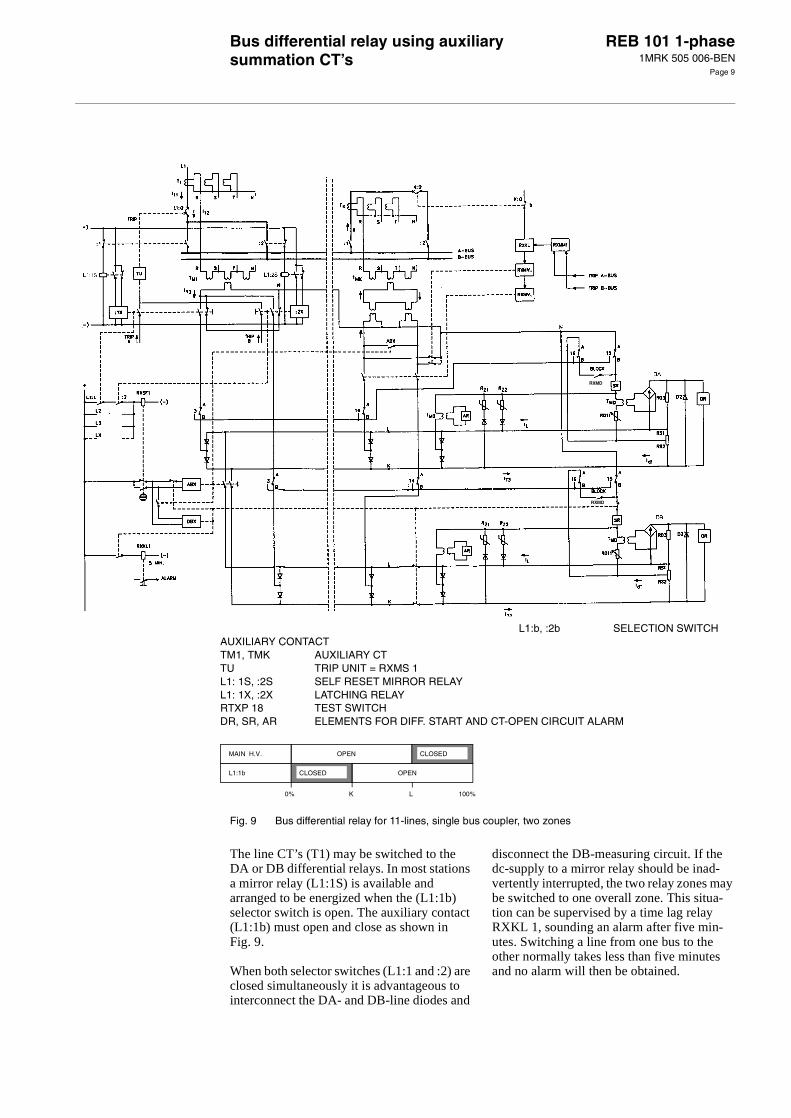
Fig. 9 Bus differential relay for 11-lines, single bus coupler, two zones
The line CT’s (T1) may be switched to the DA or DB differential relays. In most stations a mirror relay (L1:1S) is available and arranged to be energized when the (L1:1b) selector switch is open. The auxiliary contact (L1:1b) must open and close as shown inFig. 9.
When both selector switches (L1:1 and :2) are closed simultaneously it is advantageous to interconnect the DA- and DB-line diodes and
disconnect the DB-measuring circuit. If the dc-supply to a mirror relay should be inad-vertently interrupted, the two relay zones may be switched to one overall zone. This situa-tion can be supervised by a time lag relay RXKL 1, sounding an alarm after five min-utes. Switching a line from one bus to the other normally takes less than five minutes and no alarm will then be obtained.
MAIN H.V.
L1:1b
OPEN
CLOSED
CLOSED
OPEN
0% K L 100%
RXMD
RXMD
L1:b, :2b SELECTION SWITCH AUXILIARY CONTACTTM1, TMK AUXILIARY CTTU TRIP UNIT = RXMS 1L1: 1S, :2S SELF RESET MIRROR RELAYL1: 1X, :2X LATCHING RELAYRTXP 18 TEST SWITCHDR, SR, AR ELEMENTS FOR DIFF. START AND CT-OPEN CIRCUIT ALARM

Bus differential relay using auxiliary summation CT’s
REB 101 1-phase1MRK 505 006-BEN
Page 10
Design (cont’d)Design (cont’d) The bus-coupler (BC) CT-disconnection scheme serves the following purpose:
1) When the BC breaker K:0 is open a fault which occurs between the CT’s and the breaker will be disconnected instanta-neously by the correct bus differential relay.
2) If this fault occurs when K:0 is closed the wrong bus will be tripped instantaneously and the faulty bus, approx. 150 ms later.
3) If the K:0 fails to open for a proper bus fault the adjacent bus will be tripped, approx. 150 ms later.
Relay units for protective systemsSwitching line CT’s to DA, DBOrdering No. 1MRK 002 650-AA
Alternative:Ordering No. 5651 131-EA
Bus coupler CT disconnectionOrdering No. 1MRK 002 650-BA
Alternative:Ordering No. 5651 131-RA
Bus interconnection (two-zone to one zone)Ordering No. 1MRK 002 650-CA
Alternative:Ordering No. 5651 131-SA
Trip relay units for high speed trippingTrip relayOrdering: See document1MRK 508 015-BEN
Rapid operation, strong contactsOrdering No. 5651 260-A
Rapid operation, strong contacts and latchingrelaysOrdering No. 5651 261-A
101: RXMB 1 aux. relay
107: RXMD 1 latching relay
301: RXMD 2 latching relay
107101
3014U
12C
xx04000353.vsd
18C
4U
101L1:X1
301L1:X1
113
101, 301: RXMVB 2 latch-ing relay
113: RXMM aux. relay
101, 301: RXMD 2 latching relay
113: RXMB 1 aux. relay
313: RXKL 1 time-lag relay
113101
301 4S
18C
xx04000354.vsd
313
113
30C
4U
113101
125
325
101, 113: RXMVB 4 latch-ing relay
125: RXKL 1 time-lag relay
325: RXMM aux. relay
101, 301: RXMD 2 latching relay
113: RXMB 1 aux. relay
313: RXKL 1 time-lag relay
113101
301 4S
18C
xx04000354.vsd
313
113
30C
4U
113101
125
325
101, 113: RXMVB 4 latch-ing relay
125: RXSF 1 aux. flag relay
325: RXKL 1 delayed alarm relay
6C
2U
101 101: RXMS 1 with 6
make contacts
101, 301: RXMS 1 with 6 make contacts
107, 307: RXMH 2 with 8 make contacts
18C
4U
107
307
301
101
101, 301: RXMS 1 with 6 NO contacts
107, 307: RXMVB 2 latching relay with 8 makecontacts
18C
4U
107
307
301
101

Bus differential relay using auxiliary summation CT’s
REB 101 1-phase1MRK 505 006-BEN
Page 11
Technical data
Table 1: REB 101
Rated frequency 50-60 Hz
Rated current 0,5 A per input
Maximal through-going currentOperating differential current (ID1min)
2 A 5 mA
Aux voltage 48, 110, 125 or 250 V
Permitted ambient temperature -5°C to +55°C
Operating time (SR+dR)Trip impulse from diff. relay
1-3 ms 6-9 ms
Insulation tests:Dielectric tests
Impulse voltage
IEC 255-5 and ANSI C37.90 (2,5 kV and 2 kV)IEC 255-5 (5 kV)
Disturbance tests:Power frequency test:Transient test1 MHz testESD testAux. voltage interruption
SS 436 15 03, section 3,3SS 436 15 03, section 3,4 andIEC 255-22-4IEC 255-22-2IEC 255-11
Settings and estimated operating values (see Design)
Stability factor S S = = 0,5
RD3 2,2 ohm
RS/2 8 ohm
RD11 3, 6, 9 kohm
RDT RD11 + 400 ohm
RLX RLX = ≈ RDT
UT3 (DR) 25-50 V
Id1 (SR) 0,1-1,5 A
RS
nd RD3 RS2
--------+⋅⎝ ⎠⎛ ⎞----------------------------------------------
S1 S–------------- RDT⋅
Note:When technical assistance is required to choose the most suitable design, please send us a simple one line diagram with the following information:
1 Rated current for the busbar
2 Number of lines
3 Current transformer ratios for all lines
4 Rated current for all lines
5 Required primary operate current

Bus differential relay using auxiliary summation CT’s
REB 101 1-phase1MRK 505 006-BEN
Page 12
Ordering Specify:
• Ordering No. RK 638 002-AA
• Quantity
• Number of lines (12/24/36)
• Auxiliary dc voltage
• Desired wording on the lower half of the test switch face plate max. 10 lineswith 10 characters per line.
* 0 = No relays, only wired, 6 = One relay of each type, 12 = Two relays of each type
Accessories Ordering number Quantity
REB 101 extension unit 1MRK 001 428-AA
State: 12 extra lines
24 extra lines
36 extra lines
Loose SLCE 10-1 line unit summation transformer 1 pcState current ratio
1MRK 000 646-AA
Loose SLCE 10 line unit summation transformer 1 pcState current ratio
1MRK 000 646-CA
Mounting plate for 3 transformers (pre-drilled)
for SLCE 10-1 3 U 19” 2172 0615-44
for SLCE 10 4 U 19” 2172 0615-45
Switching line CT relay unitwith RXMB 1, RXMD 1 and RXMD 2alternativewith RXMM 1 and RXMVB 2State auxiliary dc voltage in both cases
1MRK 002 650-AA
5651 131-EA
Bus coupler CT disconnection relay unitwith RXMD 2, RXMB 1 and RXKL 1alternativewith RXMVB 4, RXMM 1 and RXKL 1State auxiliary dc voltage in both cases
1MRK 002 650-BA
5651 131-RA
Bus interconnection unitwith RXMD 2, RXMB1 and RXKL 1alternativewith RXMVB 4, RXSF 1 and RXKL 1State delayed alarm relay or notState auxiliary dc voltage in both cases
1MRK 002 650-CA
5651 131-SA
Trip relay unit with 2 RXMS 1 and 2 RXMH 2State auxiliary voltageState trip circuit (0/6/12) *see below
5651 260-A
Trip relay unit with 2 RXMS 1 and 2 RXMVB 2State auxiliary dc voltageState trip circuits (0/6/12) *see below
5651 261-A
For our reference and statistics we would be pleased if we are provided with the following application data:
Country: End user:
Station name: Voltage level: kV
Bus differential relay using auxiliary summation CT’s
REB 101 1-phase1MRK 505 006-BEN
Page 13
References COMBIFLEXRelay accessories and components
COMBITESTTest system
REB 101 User’s Guide
RXMS 1, RXMH 2
RXMVB 2
1MRK 513 004-BEN
1MRK 512 001-BEN
On request
1 MRK 508 015-BEN
1 MRK 508 016-BEN
Manufacturer ABB Power Technologies ABSubstation Automation ProductsSE-721 59 VästeråsSwedenTel: +46 (0) 21 34 20 00Fax: +46 (0) 21 14 69 18www.abb.com/substationautomation

Bus differential relay using auxiliary summation CT’s
REB 101 1-phase1MRK 505 006-BEN
Page 14