burnthrough round robin task group - faa fire safety test method round robin task group ... past...
TRANSCRIPT

Burnthrough Test Method Round Robin Task Group
Test Facilities FAATC-Tim Marker CEAT-Anne Mansuet Boeing-Steve Morgan Airbus-Hans Juergen Schelling Johns-Manville-Steve Volenec 3M-Tom Tompkins Mexmil-Khang Tran Accufleet-Jim Davis International Aero-John Brooks
Material Suppliers Orcon-Jim Clyne 3M-Tom Tompkins Johns Manville-Becky Wulliman Mexmil-Khang Tran TexTech Industries-Eric Ritter Inspec Foams-Dan Trahan Facile-Jim Rose Osaka Gas-Yo Ishikawa
Burner Calibration Guidelines In order to ensure that all participating labs are producing the same flame intensity level, proper calibration of the burner is necessary. In order to facilitate this, a list of guidelines has been provided below. Many of these suggestions have come from the private test labs who use this type of equipment on a daily basis, and others have come from within the FAA Technical Center from technicians/engineers with years of experience using the burner for certification tests. Additional suggestions are welcome, if they can simplify the calibration without altering its intent. Upon review of the data obtained during the initial and second Burnthrough Round Robins, a number of minor changes have been instituted in an effort to reduce the fluctuation of test results amongst the participating labs. Please review these guidelines for Burnthrough Round Robin V.

Fuel Flowrate Measurement. Prior to firing the burner the fuel flowrate must be calculated to ensure 6 gallons per hour are being delivered through the nozzle. The best method for measuring the fuel flowrate is to manually collect the fuel in a graduated cylinder for a specified period of time. To accomplish this, remove the burner cone and place a flexible piece of Tygon tubing over the fuel nozzle, turn on the motor/pump (making certain that the igniters are off!) and collect the fuel while measuring time. Typically, the fuel should be collected for a period of 1 minute or more to enable the pump to stabilize for an accurate calculation. This method also eliminates the potential discrepancies associated with in-line type flowmeters. Heat Shroud. One modification that has shown to be effective is the installation of a heat shroud over the burner draft tube (figure 1). A shroud can effectively block the transfer of heat from the flame area to the burner components such as the fuel pump, fuel lines, and burner motor. By maintaining lower temperatures of these components, proper calibration is easier to achieve.
Figure 1. Heat Shroud Installed Over Draft Tube
Intake Air Velocity. Prior to making any measurements of intake air, it is recommended that all potential air leaks be sealed in the burner housing. This equipment will typically leak around the access plate located on the rear of the unit, and also at the flange area where the igniter transformer is mounted to the main body. These areas and any other openings should be sealed with high temperature RTV or equivalent. If leaks are present, the intake air velocity measurements will be in error. After all leaks are sealed, the intake air velocity should be adjusted to 2150 +/- 50 feet per minute (FPM). The blower fan should measure 5.25 inches in diameter by 3.5 inches in depth.

Intake Air Adapter Plate. It is recommended that a suitable adapter plate be installed on the air intake side of the burner, just upstream of the air damper plate. The adapter plate will serve to hold the air velocity meter in position, and seal any air from leaking past the meter, which will result in erroneous indicated air velocity readings (figure 2). The Omega HH-30 vane-type air velocity meter is recommended for making intake air measurements, which should be carefully recorded prior to each calibration period.
Figure 2. Intake Air Adapter Plate
As an alternative to installing an adapter plate, an airbox can be constructed and mounted on the intake side of the burner as well. The airbox can be designed to house the air velocity sensor as shown in figure 3.
Figure 3. Intake Airbox

Intake Air Temperature. In order to properly calibrate the oil-fired test burner, the proper mass of air must be blended with the atomized fuel in order to achieve the desired flame output. Colder air is more dense than warm air, so the burner will require a smaller quantity of cold air for proper combustion. Past experience has shown that after the burner is calibrated in a cold test environment, substantial difficulties arise when the intake air temperature rises. The air temperature changes can be the result of running the equipment, or even daily fluctuations in the
Figure 4. Intake Air Duct ambient air. As the intake air temperature rises, more volume is needed for proper combustion. For these reasons it is recommended that conditioned air be used to feed the burner. Typical 3 or 4-inch diameter round flex hose can be used to duct air from a cool source to the burner intake (figure 4). A thermocouple inserted into the intake air stream near the airbox should be used to monitor and record the temperature during each calibration period. The intake air temperature should be kept between 60oF and 80oF (preferably 73oF and 50% relative humidity, a common standard). If conditioned air is supplied through a flex hose, this can result in lower intake air velocity. It is recommended that the air velocity meter be installed in-line nearest to the burner housing so that accurate settings can be maintained. Fuel Type/Temperature. The use of Jet A or JP-8 fuel is recommended. As the temperature of the fuel oil increases, the viscosity is reduced. As the viscosity of the fuel is lowered, the spray pattern becomes altered, and combustion efficiency is reduced. For these reasons it is recommended that the fuel temperature be maintained between 60oF and 80oF for easiest calibration. A compression fitting “T” can be installed in the fuel feed line closest to the point of entry into the burner, with a thermocouple inserted into the T fitting. The fuel temperature should be monitored and recorded during each calibration period. There are a number of devices/techniques that can be employed to keep the fuel temperature in the proper range, such as

in-line heat exchangers or by simply packing the fuel container in ice and insulating the fuel intake line. Frames for Mounting Calorimeter and Thermocouple Rake. It is recommended that suitable calorimeter and thermocouple rake test frames be constructed for measurement of the burner flame during calibration (figure 5). By incorporating individual frames for the heat flux and temperature measurement, the burner can be quickly rotated to either of the pre-positioned instruments following the 2-minute warm-up.
Figure 5. Above View of Individually Mounted Calorimeter and Thermocouple Rake Thermocouple Size. It is recommended that 1/8-inch diameter metal-sheathed, closed-bead thermocouples be used for calibration. Past experience has shown that the larger diameter units are more rugged than the smaller diameter thermocouples, which are more susceptible to breaking down after repeated use. Because the larger diameter units have more mass, the indicated temperature will be slightly lower than those measured using the smaller thermocouple diameter, and vise-versa. Similarly, a closed-bead thermocouple has a slower response than an open-bead unit, so the temperatures will also be significantly lower when using these. For this reason it is important that the calibration be performed using the specified thermocouple diameter and type. Fuel Nozzle. There are many different types of nozzles that produce vastly differing spray patterns. It is recommended that a 6.0 gallon per hour, 80o, PL (hollow cone) type nozzle be used. This will yield a hollow spray pattern, which is appropriate for this test configuration. Igniter Positioning. The spark igniters used to fire the fuel/air mix are mounted in one of the stators (turbulators) located in the draft tube area (figure 6). The entire assembly can be moved forward or backward in the draft tube, and can also be rotated 360o. Both the location and angle of the igniter assembly has been found to influence the shape of the flame, and hence calibration. The type of stator used can also impact the burner output significantly. It is highly recommended that only a Monarch H215 stator (or equivalent) be used.

Figure 6. Igniter Assembly Position
One configuration that has been found to yield the appropriate heat flux and temperature range is by positioning the igniters between 10 and 12 o’clock, as viewed looking into the end of the draft tube. The front face of the H215 turbulator is positioned 3.75 inches from the tip of the fuel nozzle (figure 7).
Figure 7. Position of Igniter Assembly
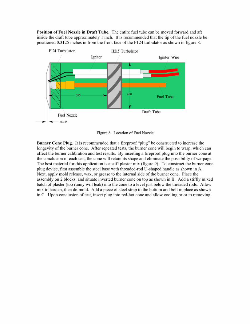
Position of Fuel Nozzle in Draft Tube. The entire fuel tube can be moved forward and aft inside the draft tube approximately 1 inch. It is recommended that the tip of the fuel nozzle be positioned 0.3125 inches in from the front face of the F124 turbulator as shown in figure 8.
Figure 8. Location of Fuel Nozzle
Burner Cone Plug. It is recommended that a fireproof “plug” be constructed to increase the longevity of the burner cone. After repeated tests, the burner cone will begin to warp, which can affect the burner calibration and test results. By inserting a fireproof plug into the burner cone at the conclusion of each test, the cone will retain its shape and eliminate the possibility of warpage. The best material for this application is a stiff plaster mix (figure 9). To construct the burner cone plug device, first assemble the steel base with threaded-rod U-shaped handle as shown in A. Next, apply mold release, wax, or grease to the internal side of the burner cone. Place the assembly on 2 blocks, and situate inverted burner cone on top as shown in B. Add a stiffly mixed batch of plaster (too runny will leak) into the cone to a level just below the threaded rods. Allow mix to harden, then de-mold. Add a piece of steel strap to the bottom and bolt in place as shown in C. Upon conclusion of test, insert plug into red-hot cone and allow cooling prior to removing.
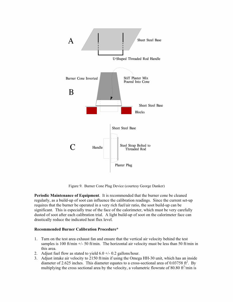
Figure 9. Burner Cone Plug Device (courtesy George Danker) Periodic Maintenance of Equipment. It is recommended that the burner cone be cleaned regularly, as a build-up of soot can influence the calibration readings. Since the current set-up requires that the burner be operated in a very rich fuel/air ratio, the soot build-up can be significant. This is especially true of the face of the calorimeter, which must be very carefully dusted of soot after each calibration trial. A light build-up of soot on the calorimeter face can drastically reduce the indicated heat flux level. Recommended Burner Calibration Procedure* 1. Turn on the test area exhaust fan and ensure that the vertical air velocity behind the test
samples is 100 ft/min +/- 50 ft/min. The horizontal air velocity must be less than 50 ft/min in this area.
2. Adjust fuel flow as stated to yield 6.0 +/- 0.2 gallons/hour. 3. Adjust intake air velocity to 2150 ft/min if using the Omega HH-30 unit, which has an inside
diameter of 2.625 inches. This diameter equates to a cross-sectional area of 0.03758 ft2. By multiplying the cross sectional area by the velocity, a volumetric flowrate of 80.80 ft3/min is

obtained. If the Omega HH30 is not being used for this measurement, simply divide the proposed flowrate (80.80 ft3/min) by the calculated cross sectional area of the device being used, and this will yield the desired air velocity setting for that particular device.
4. Prior to starting the burner, ensure that the calorimeter face and thermocouples are clean of soot deposits and that there is water running through the calorimeter.
5. Rotate the burner to the warm-up position away from the thermocouple rake and calorimeter. Examine and clean the burner cone of any evidence of buildup of soot or other products of combustion, etc. (a stainless steel wire brush is one possible cleaning tool). Soot buildup inside the burner cone can affect the flame characteristics and cause calibration difficulties.
6. While the burner is rotated out of position, turn on the fuel and light the burner. Allow it to warm up for 2 minutes, then rotate the burner into position over the calorimeter. After allowing one minute for stabilization of the calorimeter, take 30 seconds of data (once per second) and then turn the burner off and rotate out of position. The average heat flux over this 30-second interval should be 16.0 Btu/ft2 sec +/-0.8 Btu/ft2 sec. If the heat flux is not within this range, the intake air velocity can be adjusted slightly, but it should be kept between 2100 and 2200 ft/min (if using the Omega HH30 device) or 78.92 to 82.68 ft3/min volumetric flowrate. Repeat step 6 to recheck the heat flux reading. If the heat flux level cannot be obtained by adjusting the intake air damper, other adjustments may be required to obtain an acceptable heat flux reading.
7. Reposition the burner and/or calibration rig(s) to prepare for temperature readings. While the burner is rotated out of position, turn on the fuel and light the burner. Allow it to warm up for 2 minutes, then rotate the burner into position over the thermocouple rake. After allowing one minute for stabilization of the thermocouples, take 30 seconds of data (once per second) and then turn the burner off and rotate out of position. The averaged temperatures of each of the seven thermocouples must be 1900oF +/- 100oF. If the temperatures are not within this range, the intake air velocity can be adjusted slightly, but it should be kept between 2100 and 2200 ft/min (if using the Omega HH30 device) or 78.92 to 82.68 ft3/min volumetric flowrate. Repeat step 7 to recheck the temperature readings. If the temperatures cannot be obtained by adjusting the intake air damper, other adjustments such as the repositioning of the stator may be required to obtain an acceptable heat flux reading. Once the temperatures are within the acceptable range, recheck the heat flux to ensure its suitability. Further adjustments may be necessary. *These ranges are subject to change, pending adjustment of Final Rule
8. Additional parameters should be measured and recorded during each calibration period,
including the intake air temperature, the fuel temperature, the ambient temperature in the test area, relative humidity, and barometric pressure. These parameters should be measured once per second during the same 30-second period in which the heat flux/temperatures are measured. It is recommended that the tests be run at conditions within +/-10oF of the conditions at which the burner was calibrated (i.e., if the burner was calibrated using an intake air temperature of 70oF, the test should be run using an intake temperature of between 60-80oF).
Testing Guidelines Once the burner has been properly calibrated, the next important step is to ensure that all labs are conducting the test in an identical manner. Following is a list of guidelines that will help the various labs conduct the proposed burnthrough test on a similar and consistent basis. Additional suggestions are welcome, as this proposed test standard is fairly new and will likely require some streamlining in order to make it more user-friendly.

Turn on the test area exhaust fan. Before installing test blankets onto the test frame, ensure that the exit plane of the burner cone is positioned 4 inches from the outermost surface of the (third from the bottom) horizontal hat-shaped stringer (figure 10). Once the correct test position is established, rotate the burner away from the testing position, but confirm that the burner can be quickly repositioned for the test after burner warm-up.
Figure 10. Correct Positioning of the Burner with Respect to the Test Frame One of the most important details of the test involves the attachment of the samples to the test rig center vertical former, since a majority of the burner flames will impinge the samples in this area. The blanket installation should begin in this area by overlapping the 2 specimens as shown in figure 11. Secure the blankets using 12 metal spring clamps (figure 12). The spring clamps measure approximately 1.125 inch by 2 inches on each face. Four clamps should be spaced at 3, 13, 23, and 33 inches from the bottom (or top) along each of the three vertical formers (figure 13).

Figure 11. Blanket Installation Method Along Center Vertical Former
Figure 12. Metal Spring-Type Clamp Used to Secure Blankets to the Test Frame

Figure 13. Position of 12 Spring Clamps Used to Mount Insulation Blanket Samples
Following the installation of the test blankets, ensure that the 2 backside calorimeters are properly positioned at 12 inches from the front face of the hat-shaped stringer, oriented along the same axis as the burner draft tube centerline. Each calorimeter must also be positioned at 4 inches from test frame centerline, 8 inches from each other (figures 10, 11, and 13). Note the proper identification of the calorimeters; calorimeter 1 is on the left and calorimeter 2 is on the right when viewed from the cold side. Rotate the burner to the warm-up position. Turn on the motor, igniters, and fuel, and allow the burner to warm up for a period of 2 minutes. Swing the burner into the test position and simultaneously start the calorimeter data collection and timing device. Inspect the back face of the test samples for visual signs of burnthrough, and record the exact time of failure. Switch the burner off at 4 minutes* and immediately rotate out of the test position. *For the purposes of Burnthrough Round Robin V, do not switch the burner off until 6 minutes, or until a failure occurs, if prior to 6 minutes. When conducting a test in which a polyimide film material is used, it is recommended that a restraining medium be used to prevent the film enclosure from inflating due to the heating and expansion of the encapsulated air. When this occurs, it may take significantly longer to reach failure, since the film is separated from the blanket area and no longer exposed to the intense heat. Also, the film may impinge against either of the backface calorimeters, causing erroneous readings. As an alternative to restraining the blanket, it may be suitable to install several small breathing holes to allow the hot gases to escape. Pass/Fail Criteria When a visual burnthrough occurs on either of the test blankets, the burner may be turned off and rotated out of position; it is not necessary to record the heat flux levels on the backface

calorimeters. If there is no visual burnthough, the test should be run for 6 minutes, or until the backface heat flux level reaches 2.0 Btu/ft2 sec on either of the calorimeters. If this level is reached, record the exact time, as well as the heat flux level on both calorimeters. Periodic checks of the test frame dimensions are encouraged, as the intense level of heat given off by the burner can cause warpage to the frame, which could lead to misalignment of the calorimeters mounted on the backface, for example. It is recommended that 0.25-inch mild steel be used for the fabrication of the center vertical former, in order to reduce warpage. Additional Information for Round Robin V Burner Configuration. Although this document describes a specific burner configuration, your burner may be slightly different. It is possible to set the igniter position at a slightly different location in order to obtain the correct temperature profile and heat flux. This is perfectly acceptable, provided the intake air velocity and fuel flowrate are adjusted properly. Materials. Your lab will be supplied with 6 basic blanket material configurations:
Material A: 2 layers 0.60 lb/ft3 fiberglass Material B: 2 layers 0.42 lb/ft3 fiberglass + 2 layer blocking material Material C: 2 layers 0.42 lb/ft3 fiberglass + 1 layer blocking material Material D: 2 layer 0.47 lb/ft3 OPF Material E: 2 layer heat-treated OPF Material F: 3 layer heat-treated OPF
There will be six sets of samples for materials A, B, C, E and F (30 tests), and one set of sample D (1 test) for a total of 31 tests. PLEASE RUN ALL 31 TESTS, IN THE FOLLOWING ORDER: Initial Calibration A1B1C1D1E1F1 Second Calibration B2C2E2F2A2 Third Calibration C3E3F3A3B3 Fourth Calibration E4F4A4B4C4 Fifth Calibration F5A5B5C5E5 Final Calibration A6B6C6E6F6 Please condition the samples prior to testing as follows: 60-70o F, 50-60 % RH at least 24 hrs before the test day.