burners - · pdf fileto burners fueled by natural gas, placed in open air, wor-king at...
TRANSCRIPT

Burners
Dual fuel burners
EXDF - (E3611 rev. 01 - 22/06/2016)

www.esapyronics.com 2
EXDF - E3611 rev. 01 - 22/06/16
GENERAL WARNINGS:
¾¾ All installation, maintenance, ignition and setting mustbe performed by qualified staff, respecting the norms
present at the time and place of the installation.
¾¾ To avoid damage to people and things, it is essentialto observe all the points indicated in this handbook. The
reported indications do not exonerate the Client/User
from observing general or specific laws concerning acci-
dents and environmental safeguarding.
¾¾ The operator must wear proper DPI clothing (shoes,helmets...) and respect the general safety, prevention
and precaution norms.
¾¾ To avoid the risks of burns or high voltage electrocu-tion, the operator must avoid all contact with the burner
and its control devices during the ignition phase and
while it is running at high temperatures.
¾¾ All ordinary and extraordinary maintenance must beperformed when the system is stopped.
¾¾ To assure correct and safe use of the combustionplant, it is of extreme importance that the contents of this
document be brought to the attention of and be meticu-
lously observed by all personnel in charge of controlling
and working the devices.
¾¾ The functioning of a combustion plant can be dange-rous and cause injuries to persons or damage to equip-
ment. Every burner must be provided with certified com-
bustion safety and supervision devices.
¾¾ The burner must be installed correctly to prevent anytype of accidental/undesired heat transmission from the
flame to the operator or the equipment.
¾¾ The performances indicated in this technical docu-ment regarding the range of products are a result of
experimental tests carried out at ESA-PYRONICS. The
tests have been performed using ignition systems, flame
detectors and supervisors developed by ESA-PYRO-
NICS. The respect of the above mentioned functioning
conditions cannot be guaranteed if equipment, which is
not present in the ESA-PYRONICS catalogue, is used.
CONTACTS / SERVICE:
To dispose of the product, abide by the local legislations
regarding it.
DISPOSAL:
Headquarters:Esa S.p.A.
Via Enrico Fermi 40
24035 Curno (BG) - Italy
Tel +39.035.6227411
Fax +39.035.6227499
International Sales:Pyronics International s.a.
Zoning Industriel, 4ème rue
B-6040 Jumet - Belgium
Tel +32.71.256970
Fax +32.71.256979
www.esapyronics.com
GENERAL NOTES:
¾¾ In accordance to the internal policy of constant quali-ty improvement, ESA-PYRONICS reserves the right tomodify the technical characteristics of the present docu-ment at any time and without warning.
¾¾ It is possible to download technical sheets whichhave been updated to the latest revision from the www.esapyronics.com website.
¾¾ The EXDF products have been designed, manufactu-red and tested according to the most correct construc-tion practices and following the applicable requirementsdescribed in UNI EN 746-2-2010 “Industrial heating pro-cess equipment - Part 2: Safety requirements for com-bustion and for the handling and processing of fuels’.We emphasize that the burners described in this datasheet are provided as independent units and areexcluded from the scope of the Machine Directive2006/42/EC not having any mobile items that are notexclusively manual.
¾¾ Certified in conformity with the UNI EN ISO 9001Norm by DNV GL.
CERTIFICATIONS:
The products conform to the requests for the Euroasia market
(Russia, Belarus and Kazakhstan).

www.esapyronics.com 3
EXDF - E3611 rev. 01 - 22/06/16
APPLICATIONS
The EXDF burners are dual “fuel nozzle mixing” burners
with refractory blocks.They can burn all types of commer-
cial non-corrosive gases or oils with maximum viscosity
of 3 ° E. The fuel and the combustion air are mixed at the
point of ignition within the refractory cone avoiding the
danger of backfiring. The characteristics of the refractory
block are such as to allow excellent flame stability and
remarkable flow ratio. All the burners of the EXDF series
can operate with stoichiometric combustion fuel ratios or
with excess air while maintaining a remarkable stability of
the flame.
¾¾Kilns for ceramic firing
¾¾Sanitary firing furnaces
¾¾Forging furnaces
¾¾Annealing furnaces
¾¾Reheating furnaces
¾¾Melting furnaces
¾¾Drying furnaces.
¾¾Incenerators
¾¾Furnaces for metal, resin and polymer treatment
¾¾Hot air generatorsF3611I03
F3611I04
CHARACTERISTICS
GENERAL:
¾¾Oil functioning capacity: from 100 to 1650 kW
¾¾Gas functioning capacity: from 90 to1450 kW
¾¾Functioning with preheated air up to: 450°C
¾¾Air and gas pressure to the burner: 70 mbar
¾¾Oil pressure to the burner: 2 bar
¾¾Operation with various types of gases:CH4/LPG/Propane/etc...
¾¾Functioning with various types of maximum viscosityoils: 3°E
¾¾Flow ratio with gas operation: 8÷1
¾¾Flow ration with oil operation: 6÷1
¾¾Separate air , gas and oil inlets, nozzle mixing, noflash backs.
¾¾Modular design to facilitate assembly, maintenanceand cleaning.
MATERIAL COMPOSITION:
¾¾Mixer body and air/gas collector: Cast iron G25
¾¾Plate: Cast iron G25
¾¾Fuel lance: AISI 304

www.esapyronics.com 4
EXDF - E3611 rev. 01 - 22/06/16
IGNITION AND DETECTION
The EXDF burners must always be ignited with a DSP
electrode or pilot burner in compliance with the EN746
Norm. The pilot burner must be excluded after ignition of
the main burner and therefore ignition must take place via
a photocell.
ModelIgnition with pilot burner Ignition with electrode
Ignition Detection Ignition Detection
12 EXDF P64PBC-FR UV-2 DSP-1 UV-2
16 EXDF P64PBC-FR UV-2 DSP-2 UV-2
24 EXDF P86PBC-FR UV-2 DSP-3 UV-2
32 EXDF P86PBC-FR UV-2 DSP-3 UV-2
48 EXDF P86PBC-FR UV-2 DSP-4 UV-2
Provide a cooling line for ignition electrode (copper pipe
ø 8) and for the photocell in case it is mounted on refrac-
tory block housing. The adoption of flame control systems
is strongly recommended in all systems operating at tem-
peratures below 750 ° C (UNI EN746-2).
CAPACITY PARAMETERS AND FLAME LENGTH
Model
Type of
refractory
block
(1)
Capacity[kW]
Flame
length[mm]
Diameter
of refrac-
tory block[mm]
Flue gas outlet speed
@1500°C [m/s]
a 0m a 0,5m a 1m a 1,5m a 2m a 2,5m a 3m
12 EXDFM
102 300÷500106 60 38 19 13 9 7,5 6
H 50 90 48 24 17 12 9 7,5
16 EXDFM
203 600÷800129 60 52 26 19 14 11 10
H 74 90 58 33 22 17 14 12
24 EXDFM
407 1000÷1250190 (129) 60 53 27 20 15 12 11
H 108 90 74 40 27 21 17 14
32 EXDFM
814 1250÷1500190 60 52 28 22 17 14 12
H 149 90 62 36 25 19 15 13
48 EXDFM
1628 2000÷2500280 60 54 32 27 21 19 16
H 212 90 63 38 27 21 16 14
4X48 EXDF* M 6512 2000÷2500 4X280 60 55 34 28 22 20 17
The flame lengths and speeds are approximate, referred
to burners fueled by natural gas, placed in open air, wor-
king at stoichiometric ratio and at nominal capacity.
In special applications, a mono electrode is used for igni-
tion and flame detection or an electrode for ignition and a
UV photocell for flame detection.
(*) Where higher potential with small flame lengths is needed other multiblock models are available on request.
1 M: Flame output speed 50÷60 m/s
H: Flame output speed 80÷90 m/s
www.esapyronics.com 5
EXDF - E3611 rev. 01 - 22/06/16
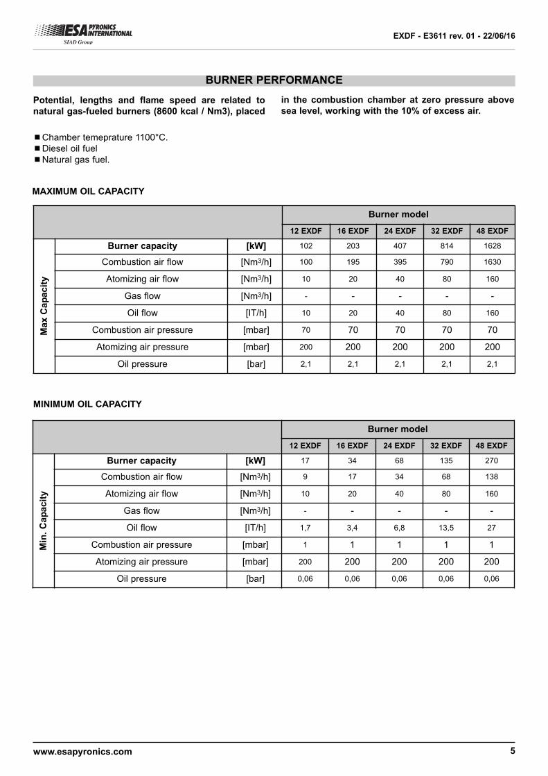
BURNER PERFORMANCE
¾¾Chamber temeprature 1100°C.
¾¾Diesel oil fuel
¾¾Natural gas fuel.
MAXIMUM OIL CAPACITY
MINIMUM OIL CAPACITY
Potential, lengths and flame speed are related tonatural gas-fueled burners (8600 kcal / Nm3), placed
in the combustion chamber at zero pressure abovesea level, working with the 10% of excess air.
Burner model
12 EXDF 16 EXDF 24 EXDF 32 EXDF 48 EXDF
Burner capacity [kW] 102 203 407 814 1628
Combustion air flow [Nm3/h] 100 195 395 790 1630
Atomizing air flow [Nm3/h] 10 20 40 80 160
Gas flow [Nm3/h] - - - - -
Oil flow [IT/h] 10 20 40 80 160
Combustion air pressure [mbar] 70 70 70 70 70
Atomizing air pressure [mbar] 200 200 200 200 200
Oil pressure [bar] 2,1 2,1 2,1 2,1 2,1
Max C
ap
acit
y
Burner model
12 EXDF 16 EXDF 24 EXDF 32 EXDF 48 EXDF
Burner capacity [kW] 17 34 68 135 270
Combustion air flow [Nm3/h] 9 17 34 68 138
Atomizing air flow [Nm3/h] 10 20 40 80 160
Gas flow [Nm3/h] - - - - -
Oil flow [IT/h] 1,7 3,4 6,8 13,5 27
Combustion air pressure [mbar] 1 1 1 1 1
Atomizing air pressure [mbar] 200 200 200 200 200
Oil pressure [bar] 0,06 0,06 0,06 0,06 0,06
Min
. C
ap
acit
y

www.esapyronics.com 6
EXDF - E3611 rev. 01 - 22/06/16
BURNER PERFORMANCE
MAXIMUM NATURAL GAS CAPACITY
MINIMUM NATURAL GAS CAPACITY
Burner model
12 EXDF 16 EXDF 24 EXDF 32 EXDF 48 EXDF
Burner capacity [kW] 92 183 366 733 1465
Combustion air flow [Nm3/h] 101 201 402 806 1610
Atomizing air flow [Nm3/h] - - - - -
Gas flow [Nm3/h] 9,2 18,3 36,6 73,3 147
Oil flow [IT/h] - - - - -
Combustion air pressure [mbar] 70 70 70 70 70
Atomizing air pressure [mbar] - - - - -
Oil pressure [bar] - - - - -
gas Δp [mbar] 10 10 10 10 10
Max.
Cap
acit
y
Burner model
12 EXDF 16 EXDF 24 EXDF 32 EXDF 48 EXDF
Burner capacity [kW] 12 23 45 92 185
Combustion air flow [Nm3/h] 13 25 50 102 203
Atomizing air flow [Nm3/h] - - - - -
Gas flow [Nm3/h] 1,2 2,3 4,5 9,2 18,5
Oil flow [IT/h] - - - - -
Combustion air pressure [mbar] 1,1 1,1 1,1 1,1 1,1
Atomizing air pressure [mbar] - - - - -
Oil pressure [bar] - - - - -
gas Δp [mbar] 0,2 0,2 0,2 0,2 0,2
Min
. C
ap
acit
y

www.esapyronics.com 7
COMBURENT AIR INLET
M
FCV12
TO OTHER BURNERS
BE15
BD14
BI16
BMS17
BT
18
ATOMIZING AIR INLET
HV10
FCV11
TO OTHER BURNERS
F02
S
SV04
HV01
PCV03
OIL INLET
TO OTHER BURNERS
HV06
PCV07
S
SV08
TO OTHER BURNERS
GAS INLET
S
SV08
S
SV04
FCV13
FCV09
FCV
05
APPLICATION EXAMPLES
D3611I01
Pos. Description Included Not included
HV 01 Oil interception valve X
F 02 Oil filter X
PCV 03 Oil pressure regulator X
SV 04 Oil safety valve X
FCV 05 Oil interception valve X
HV 06 Gas interception valve X
PCV 07 Zero governor X
SV 08 Gas safety valve X
FCV 09 Gas adjuster X
HV 10 Atomizing air interception valve X
FCV 11 Atomizing air regulation valve X
FCV 12 Combustion air regulation valve X
FCV 13 Manual air regulation valve X
BD 14 Flame detection X
BE 15 Burner X
BI 16 Burner ignition X
BMS 17 Flame control X
BT 18 Ignition transformer X
EXDF - E3611 rev. 01 - 22/06/16

www.esapyronics.com 8
EXDF - E3611 rev. 01 - 22/06/16
WARNINGS
¾¾ The burners of EXDF series are intended for use infixed installation. If mobile installations are needed (bell
furnaces, etc ...) it is necessary to evaluate the possibi-
lity of any damages determined by the movement of the
actual furnace
¾¾ Burner ignition must be always performed at minimumpower, then modulating towards the maximum, facilita-
ting ignition and reducing outlet overpressure.
¾¾ Moving from minimum to maximum power, and viceversa, should be gradual and not instantaneous.
¾¾ For all low-temperature applications (up to 750 °C),burner ignition and the control of the fuel gas solenoid
valves must be performed by a certified burner control
device.
¾¾ It is always necessary to use flexible couplings in thepresence of preheated air.
¾¾ To avoid possible damage to burners, make sure thatthe blower does not send them air that may be fouled by
combustion products, oils, solvents or other. To avoid
these phenomena from taking place, possibly install the
blower or the suction duct outside the establishment and
far from the exhaust pipes.
¾¾ Check the correct connection of the feeding lines afterinstallation. Before switching the burner on, check that
the combustion air and fuel gas pressure values are cor-
rect.
¾¾ The burner can only function within the indicatedpower range. Functioning at lower or higher power could
compromise the burner performance as well as its life
span. In which case, the general warranty conditions will
automatically expire and ESA will not be held responsi-
ble for any damage to persons or objects.
¾¾ If there is trouble with other devices during the burnerstart up phase, use the connector with anti disturbance
filter for the high-tension (HT) cable connection of the
ignition electrode.
¾¾ Avoid burner ignition close to each other so as not toheat the ignition command system devices (solenoid
valves and transformers). Prewash time lapse + first
safety time lapse + min. of 5 sec. = time lapse between
one ignition and another. (however, do not attempt more
than 2 ignitions during a 30sec. time lapse).
¾¾ Make sure the power supply is TURNED OFF whenintervening on the burner and its devices. In case of bur-
ner malfunctioning, follow the indications in the
'Maintenance' chapter of the present manual or contact
ESA-PYRONICS assistance.
¾¾ Any modification or repair done by third parties cancompromise the application safety and automatically
causes the general warranty conditions to expire.

www.esapyronics.com 9
EXDF - E3611 rev. 01 - 22/06/16
INSTALLATION
The EXDF burners are generally installed on the furnacewalls. Roof mounting is unadvisable; in any case, if it isnecessary, please specify during the order phase.
The light needed for the burner housing must have suffi-cient open space around the refractory block for the cera-mic fibre insulation (which is already supplied with theburner). Please refer to the OVERALL DIMENSIONSchapter for this process.
The use of flexible hoses and / or compensators for con-nection of the air and gas lines is mandatory. The air andgas inlets have flanges (threaded or to be welded) andcan freely rotate at a 90° angle.We recommend you install the refractory block with theholes for the pilot burner and flame detection photocell onthe upper part.
03
01
02
CERABIC FIBERINSULATION
DO NOT REMOVE!
04
D3611I02
Installation with the holes at the bottom could create pro-blems.
1 - Insert on the furnace wall (pos.01).
2 - Lift the burner (pos.03) and fix it to the studs (pos.02)with nuts (pos.04), checking that the ceramic insulation-surrounding the block does not get damaged while inser-ting the block in the hole, and that the gasket does notmove or get deformed.
3 - Tighten the fixing nuts the furnace wall flange leavingthem loose to allow the burner refractory block to floatduring heating.
4 - Connect the air and gas lines of the burner with thefixing flanges.
5 - Carry out the first furnace heating following the appro-priate refractory material drying curves.
6 - Once the maximum operating temperature is reached,finally tighten the fixing nuts.
7 - After heating the first time, immediately repair possiblecracks or small damage. Generally the furnace wallsaround the burner must be inspected regularly and allcracks are to be repaired or patched up. This avoids hotgas leaks inside the cracks damaging the metallic parts of
the furnace or burner.
8 - If blocks with metal casing are used, the metal casingmust be appropriately protected from the high temperatu-re of the furnace.
9 - Burner housing must be built with suitable burner sup-ports to prevent possible collapsing of the refractory block.The refractory block must not protrude from the wall. If itdoes, provide suitable spacers to move it back to its posi-tion compared to the inner furnace wall.

www.esapyronics.com 10
IGNITION - SETTING
The operations indicated in the following chapter must be
carried out by expert technicians or qualified staff. The
inobservance of the instructions could generate dange-
rous conditions.
1 - Check that the combustion air pressure on the blower
outlet, gas and fuel oil feeding pressures are within the
allowed range.
2 - Regulate the operating and intervention pressures of
the combustion plant safety devices whether there is one
per burner or one general device for the entire combu-
stion plant such as: gas pressure reducer, shut off valve,
presure relief valve, pressure switches etc. Simulate the
intervention of all the safety devices including the high
temperatire safety intervention checking that the fuel shut
off devices act correctly.
3 - Place the air regulation valve in the maximum opening
position and adjust, via the gate valve referring to the
values indicated in the “Burner Performance” chapter for
the maximum capacity on pages 04 and 05.
4 - Place the motorized air regulation valve in the mini-
mum opening position and adjust the opening to obtain
(on the burner input) the pressure related to the minimum
power.
5 - Activate the burner control device and run a few
attempts to switch on the pilot burner (*) until the burner
lights up. During the ignition attempts, act on the gas or oil
control valve and, starting from the totally closed position,
open it gradually until burner ignition is obtained.
EXDF - E3611 rev. 01 - 22/06/16
6 - Place the air regulation motorized valve at its maxi-
mum opening position and adjust, via the gas and oil
regulation valve, the maximum fuel flow, checking the dif-
ferential pressure that is created on the calibrated gas
flange or the pressure on th eoil lance input. The calibra-
tion at mininmum is done with the air valve at its mini-
mum, acting on the adjustment screw placed inside the
pneumatic regulator.
7 - Check again that, at minimum and maximum power,
the burner air inlet pressure corresponds to what is indi-
cated in the “Burner performance” chapter. It is possible
that, with the burner running, the values are different in
comparison to those with burner off.
8 - With the furnace at the correct temperature, carry out
an analysis of the combustion products on the burner
chimney with a portable analyzer and if necessary adjust
the air and gas pressure (Reference value of O2 at max
power of 2÷4%, at minimum power 3÷6%).
9 - Possibly with all the burners running at the same pow-
wer, analyze the combustion products in the chamber
(where possible).
10 - Perform repeated ignition attempts .at minimum bur-
ner power with temperature variations at maximum to
check ignition reliability and flame stability during regula-
tion.
(*) For ignition and setting of the pilot burner refer to the
data sheet E3280.

www.esapyronics.com 11
EXDF - E3611 rev. 01 - 22/06/16
TRANSITION FROM OPERATION WITH OIL TO OPERATION WITH GAS
TRANSITION FROM OIL TO GAS
1 - Close the manual interception valve on the fuel oil
line
2 - Close the manual interception valve on the atomizing
air line.
3 - Loosen the grub screw (pos. 01) to unblock the move-
mento of the oil lance (pos.02).
4 - Pull the oil lance (pos. 02) until reaching the maximum
extractable position.
5 - Screw on the grub screw (pos. 01) until blocking the oil
lance in the maximum extractable position.
6 - Open the manual interception valve on the fuel gas
line.
7 - Adjust the gas flow according to the indications
contained in the BURNER PERFORMANCE section.
0102
D3611I03
TRANSITION FROM GAS TO OIL
1 - Close the manual interception valve on the fuel oil
line.
2 - Loosen the grub screw (pos. 01) to unblock the move-
mento of the oil lance (pos.02).
3 - Release the oil lance (pos.02) oil up to the stop posi-
tion (minimum extraction position).
4 - Screw on the grub screw (pos. 01) until blocking the oil
lance in place.
5 - Open the manual interception valve on the fuel gas
line.
6 - Open the manual shut-off valve on the air atomization
line.
7 - Adjust the atomizing air and fuel oil flow according to
the instructions contained in the BURNER PERFORMAN-
CE section.
0102
D3611I04
The EXDF burners can work with both liquid fuel (oil with
a maximum viscosity of 3°E) as well as gas fuel (class
1/2/3). The transition from one type of fuel to the other
takes place quickly and respecting the instructions below:

www.esapyronics.com 12
EXDF - E3611 rev. 01 - 22/06/16
GENERAL MAINTENANCE PLAN
NOTES:
Key: O = ordinary / O = extraordinary
(*) We advise you to replace the gas side gaskets after every time the gas feeding line is disassembled and to use high
temperature gaskets.
Operation Type Advised time Notes
Pilot burner electrode high voltageconnector
O annual
verify integrity of the outer plastic and
oxidation of the internal connector and
the electrode terminal.
Pilot burner ignition electrode O annualreplace in the case in which the termi-
nal Kanthal is worn.
Integrity of refractory block S every six months
from the inside check the presence of
any cracks in the refractory material
every time the furnace is stopped for
maintenance. If there are cracks they
must be filled with appropriate refractory
material or sealant.
Cleaning of the photocelllass O every six monthsreduce to quarterly in dusty environ-
ments.
Photocell replacement O10.000 h.
of operationin any case every 2 years.
Gaskect replacement on gas side (*) O every two years see note.
Burner setting O annualrepeat all the steps on “Ignition and
Setting” chapter.
Cleaning of oil lance O every six months
disassemble the elements ofthe nozzle
and clean it from any deposits. Clean
more often in the case of oils not ade-
quately filtered.

www.esapyronics.com 13
EXDF - E3611 rev. 01 - 22/06/16
1 2
3 4 5
6 7
D3611I05
ORDINARY MAINTENANCE
For correct dismantling and better maintenance of EXDF
burners, meticulously follow the instructions below with
the plant turned off.
CLEANING OF PHOTOCELL GLASS
1 - Make sure the burner control device is not connected.2 - Disconnect power supply to the photocell (pos. 01)and the cooling line (where present pos. 07).3 - Unscrew the aluminum pipe fitting (pos. 06) at thebase of the gas collector, removing the photocell with its
spacer.4 - Unscrew the aluminum pipe fitting from the insulationteflon connector (pos. 03) and pull out the quartz watchglass (pos. 05).5 - Clean the quartz watch glass with a soft cloth andreassemble everything, taking care to check the correctposition of the glass and seals (pos. 04) between the alu-minum spacer and teflon, before tightening.6 - Restore the cooling pipe and the electrical connec-tion.7 - Check the correct flame detection by the photocell.

www.esapyronics.com 14
EXDF - E3611 rev. 01 - 22/06/16
For correct dismantling and better maintenance of NM
burners, meticulously follow the instructions below with
the plant turned off.
BURNER IN LOCKOUT
In burner lockout conditions refer to the instructionsof the burner control device and the relative manualto identify the cause. The following are the maincases:
¾¾Illegal flame detection: lockout due to the detection
of an illegal flame signal during the phases prior to igni-
tion or following the shutdown. The causes are to be
found in the detection system (faulty sensor or presence
of humidity), or in a gas drawn by the safety valve that
allows the burner to remain turned on.
¾¾Ignition failed: lockout due to missing flame formation
during start-up. The causes are to be found in the igni-
tion system (spark absence, faulty or not in the correct
position) electrodes, the incorrect adjustment of the fuel
flow and combustion, or in the detection system (faulty
sensor or interrupted cables). Specifically, in the first two
EXTRAORDINARY MAINTENANCE
cases the flame does not ignite, whilst in the last case,
the flame forms but the burner control device is not able
to detect it.
¾¾Flame signal loss: lockout due to flame signal loss
during the normal operation of the burner. The causes
are to be found in the regulation of the combustion air
and fuel flows (rapid changes in flow, control out of
range) or in the detection system (faulty, dirty or badly
positioned sensors).
PHOTOCELL REPLACEMENT
1 - Make sure the burner control device is not connected.2 - Disconnect power supply to the photocell (pos. 01)and the cooling line (where present).3 - Unscrew the aluminum pipe fitting at the base of thegas collector (pos. 02), removing the photocell with itsspacer.4 - Screw in the same position the new component afterchecking the correct position of the insulating glass bet-ween the aluminum and teflon spacer.5 - Restore the cooling hoses and electrical connection.6 - Check the correct flame detection by the photocell.

www.esapyronics.com 15
EXDF - E3611 rev. 01 - 22/06/16
OVERALL DIMENSIONS - EXDF ROUND REFRACTORY BLOCK
Ø"M
"
F
UR
NA
CE
CU
T O
UT
"N
"
CERAMIC FIBER INSULATION BY ESA.DO NOT REMOVE!
"G"
"L"
"H"
"J"±10
COMBUSTION AIRINLET ØA"
ATOMIZINGAIR INLET Ø"B"
"T"
"R"
"S"
Ø"P"
45°
N
r. 8
slo
ts "
Q"
UV SCANNERSOCKET ØD"
INGNITIONSOCKET Ø"E"
OIL INLETØ"C"
PEEPSIGHTSOCKET Ø"F"
"O"
Model ø “A” ø “B” ø “C” ø “D” ø “E” ø “F”
12EXDF G 1.1/2” G 3/4” Rp 1/8” G 3/4” G 3/4” G 3/4”
16EXDF G 2” G 1” Rp 1/8” G 3/4” G 3/4” G 3/4”
24EXDF DN80 G 1.1/2” Rp 1/4” G 3/4” G 1” G 3/4”
32EXDF DN100 G 2” Rp 1/4” G 3/4” G 1” G 3/4”
48EXDF DN150 DN80 Rp 1/4” G 3/4” G 1” G 3/4”
D3611I06
Model G mm H mm J mm L mm ø M mm ø N mm O mm P mm Q mm R mm S mm T mm Massa Kg
12EXDF-R 117 200 337 228 178 191 □ 222 □ 254 14 87 80 21 23,1
16EXDF-R 120 228 364 254 203 216 ø 289 ø 330 16 101 80 21 31,5
24EXDF-R 228 359 506 305 298 311 ø 349 ø 406 16 126 107 26 73,2
32EXDF-R 228 359 506 305 298 311 ø 349 ø 406 16 122 107 26 72,5
48EXDF-R 233 464 618 330 400 412 ø 457 ø 508 16 156 130 26 130,5

www.esapyronics.com 16
EXDF - E3611 rev. 01 - 22/06/16
OVERALL DIMENSIONS - EXDF SQUARE REFRACTORY BLOCK
CERAMIC FIBER INSULATION BY ESADO NOT REMOVE!
o"P"
o"O"
o"M
"
FU
RN
AC
E C
UT
OU
T o
"N"
COMBUSTION AIRINLET ØA"
ATOMIZING AIROR GAS INLET ØB"
"G"
"L"
"H"
IGNITIONSOCKET Ø"E"
UV SCANNERSOCKET Ø"D"
"J"±10
OIL INLETØ"C"
"S"
"R"
"T
"
Nr.8
slo
ts "
Q"
PEEPSIGHTSOCKET
Ø"F"
Model ø “A” ø “B” ø “C” ø “D” ø “E” ø “F”
12EXDF G 1.1/2” G 3/4” Rp 1/8” G 3/4” G 3/4” G 3/4”
16EXDF G 2” G 1” Rp 1/8” G 3/4” G 3/4” G 3/4”
24EXDF DN80 G 1.1/2” Rp 1/4” G 3/4” G 1” G 3/4”
32EXDF DN100 G 2” Rp 1/4” G 3/4” G 1” G 3/4”
48EXDF DN150 DN80 Rp 1/4” G 3/4” G 1” G 3/4”
D3611I07
Model G mm H mm J mm L mm □ M mm □ N mm O mm P mm Q mm R mm S mm T mm Massa Kg
12EXDF-R 117 200 337 219 178 191 □ 222 □ 254 14 87 80 21 27,6
16EXDF-R 142 250 386 254 229 241 □ 278 □ 330 16 101 80 21 48,1
24EXDF-R 190 231 468 241 419 432 □ 464 □ 508 16 126 107 26 136,8
32EXDF-R 190 231 468 241 419 432 □ 464 □ 508 16 122 107 26 136,1

www.esapyronics.com 17
EXDF - E3611 rev. 01 - 22/06/16
OVERALL DIMENSIONS - 48 EXDF MULTI TUNNEL MODEL
n1
01
6
FU
RN
AC
E C
UT
OU
T Ø
10
29
400
173
412
583
13
0
15
6
OIL INLETRp 1/4"
GAS OR ATOMIZINGAIR INLET DN80
COMBUSTION AIRINLET DN150
15°
!1220
Nr.24 holes !22
36
8
= =
368
= =
INGNITIONSOCKET Rp1"
DETECTIONSOCKET Rp1"
PEEPSIGHTSOCKET Rp1"
Ø2
80
Ø2
80
D3611I07

www.esapyronics.com 18
ORDERING CODE- COMPLETE BURNER
ORDERING CODE - ONLY REFRACTORY BLOCK
- -EXDF ---
MODEL
12EXDF16EXDF24EXDF... (see capacity table)
121624.....
IGNITION
Electrode
Pilot
EP
GAS ADJUSTER
With gas adjusterFlange
GA*F
ALLOY JACKET REFRAC-TORY BLOCK
Without jacketWIth jacket
2D
01
REFRACTORY BLOCK
Round blockSquare block
RS
02
01 02 03 04 05- -
06 07
05
06
07
EXDF BH- ---
MODEL
12EXDF16EXDF24EXDF... (see capacity table)
121624.....
ALLOY JACKET REFRAC-TORY BLOCK
Without jacketWIth jacket
2D
01 REFRACTORY BLOCK
Round blockSquare block
RS
03
01 02 03-
04
04
EXDF - E3611 rev. 01 - 22/06/16
FUEL
MethaneLPGPoor gas (1)
CH4GPLGP
03
LOCKOUT TYPE (2)
Medium velocityHigh velocity
MH
04
TYPE OF BLOCK (2)
Medium velocityHigh velocity
MH
02
(*) The codes marked with an asterisk identify the standards.
Notes:
1Particular performance according to gas characteristics.
2see “Parameter potential and flame length” table