bunda - territory stories: home · technical report wrd96017 viewed at 20:02:08 on 17/02/2010 page...
TRANSCRIPT

Technical Report WRD96017
Viewed at 20:02:08 on 17/02/2010 Page 1 of 38.
~ .... ,
•·••••• .•.• x·;;;:·
BUNDA
1\1// $&6 '7J <::> I 'i?b .2
'l!' 0 3 '6 6 S
" .... .£b '/';3.!> /,; ~6 7:;-1>1
0,oS6 20,076
<, ?4-2 z ~1, 8:<
I ?b
U 2- 7 If. 2.IJ7'7 211-7.5'1 :z S ~ ~2 ;;!.7'VU
'27 too ;i ••• ) .•••• .'", Z 7 66 {
'$),,?
1/711--rs '} 5 57,.
"'001 7 .;Lo 4-"3 f!- 0 '7'" 9- (:;) '1S i/- 7 IJ' ,';-5.t;'2
1>'6 I 6iS:;: t-o 2 I & (, '30
ZS ZoO
,z52"'" 2£7 "g 2 7 :J?fO '\.0) "7

Technical Report WRD96017
Viewed at 20:02:08 on 17/02/2010 Page 2 of 38.
WATER RESOURCES SURVEY OF BUKDA AKD KIRKlYlBIE STATIONS NORTHER'll TERRITORY
List of Abbreviations
List of Conversions
SUMMARY
1. INTRODUCTION
2. WATER SUPPLY DEVELOPrvlENT
3. GROUNDWATER
3.1 Areas with yields 0.5 to 5.0 Us 3.2 Areas with yields more than 5 Lis
4. SURFACE WATER
4.1 Surface Water Storage Types 4.2 Selection of Sites for Excavated tanks 4.3 Design and Construction of Excavated tanks 4.4 Waterholes and Springs 4.5 Piping of Surface Water 4.6 Supply of Stock Water from Tanks
5.RECOMrvlENDATIONS
5.1 Water Supply Distribution 5.2 Groundwater 5.3 Surface Water
6.ACKNOWLEDGrvlENTS

Technical Report WRD96017
Viewed at 20:02:08 on 17/02/2010 Page 3 of 38.
APPENDICES
Appendix 1: Station bores Appendix 2: Chemical analyses of ground waters Appendix 3: Water quality requirements for stock and domestic water Appendix 4: Pumping test results Appendix 5: Dams and waterholes Appendix 6: Site investigations Appendix 7: Construction details of excavated tanks, turkey nests and modified waterholes Appendix 8: Glossary
TABLES
1. Climatic averages
FIGURES
I. Locality diagram 2. Landform map 3. Standing water levels in bores 4. Types oftanks and dams 5. Typical offstream excavated tank 6. Typical drainage-line excavated tank 7. Sketch showing improved size of grazing area due to piping away from a reliable bore or tank 8. Test hole plan for an excavated tank
MAPS
1. Water Resources Development Map of Bunda Station, including side maps showing Groundwater and Surfacewater Resources
2. Water Resources Development Map of Kirkimbie Station, including side maps showing Groundwater and Surfacewater Resources

Technical Report WRD96017
Viewed at 20:02:08 on 17/02/2010 Page 4 of 38.
LIST OF ABBREVIATIONS
kIn Us m m3
mgIL ML mm ,uS/cm pH TDS
kilometre - litres per second
metre - cubic metre - milligrams per litre - megalitre (one million Iitres)
millimetre - microsiemens per centimetre
- acidity and alkalinity index - total dissolved solids
LIST OF CONVERSIONS
1 mm (millimetre) - .04 inches (4 points) I m (metre) - 3.3 feet I kIn (kilometre) - 0.6 miles 1 L (litre) - 0.22 gallons 1 ML (megalitre) = 220,000 gallons I Lis (litre per second) - 800 gallons per hour

Technical Report WRD96017
Viewed at 20:02:08 on 17/02/2010 Page 5 of 38.
SUMMARY The accompanying Water Resources Development maps can be used as a guide to detennine the type of water supply most appropriate to specific areas of the stations. Groundwater is generally available in most areas however in situations where surface water flows and soil types are suitable. excavated tanks away from dearly defined drainages, and sited to harvest sheet flow are an alternative option to bores. Site investigations are essential to detennine if there is sufficient depth of clay subsoil, to ensure that the tank will not leak. The reliability of existing tanks can be improved in some cases by deepening where appropriate. All existing and planned surface water storages including excavated tanks, waterholes and springs should be fenced and stock watering infrastructure provided. Both stations have an adequate distribution of watering points in most areas.
1. INTRODUCTION This project was started by the Victoria River District Conservation Association (VRDCA). It s aim is to provide station managers \vith up to date infonnation on water resources, so that they can make more informed decisions about water and land management. It is funded by the Northern Territory Government and the National Landcare Program with a contribution by the VRDCA. A total of 20 properties will be studied between July 1993 and June 1998.
Bunda and Kirkimbie stations cover an area of l790km' and 2312km' respectively and are located adjacent to the Western Australian border some 250 kilometres southeast from Kununurra, the closest major town. Road access is via the Buchanan Highway which remains open for most of the year (Figure 1). During the wet season many station tracks may be impassable. The availability of stock water is the major influence on stock management. Nearly all of the annual rainfall, which ranges from approximately 595mm on Kirkimbie to 493mm on Bunda, occurs in the short hot monsoonal wet season between December and March (Table I). Little rainfall is experienced during the remainder of the year. During the Wet, when the streams flow, much of the low lying country is inundated. Recharge to groundwater aquifers occurs at this time. Evaporation rates of water bodies such as dams or lakes are between 4.5 and 8.2 millimetres per day (average about 6.8 mm per day or 2.6 metres per year). This
Water Resources of Bllnda & Kirkimbie
ensure that water levels in creeks, dams and tanks decline rapidly. Air temperatures are high throughout the year. The average monthly maxima range from about 26.5 degrees in June to 38.0 degrees in December. The corresponding average monthly minima are 9.7 and 22.9 degrees.
Current stock management is based on water aVailability. At present each station carties about 10,000 head of cattle. Bores supply approximately 85% of their water needs, the remainder coming from dams, springs and waterholes. Groundwater is the major water source, particularly in the Dry. Twentythree bores are used (fifteen on Kirkimbie and eight on Bunda), normally in conjunction with turkey nests which act as temporary storages. During the Wet and the early Dry, some surfacewater is used, but as the Dry progresses, these sources become depleted and more reliance is placed on groundwater. None of the man made storages nonnally last until the end of the Dry. There are two excavated tanks on Bunda and five on Kirkimbie.
The stations can be classed into four broad landform types, laterite plateau, low hills and ranges, black soil plains and the dissected plateau and (Figure 2). Most pastoral development is undertaken on the black soil plains because they support better pasture and are more accessible. The divide between streams flowing to the sea in the Negri lOrd River catchment and those flowing inland in the Stnrt Creek catchment
Pagel

Technical Report WRD96017
Viewed at 20:02:08 on 17/02/2010 Page 6 of 38.
>'" o
MISTAKE CREEK
!::: '" WAllAMUNGA <= l!!
I KIRKIMBIE ,
" BUNDA
TENNANT CREEK
I , I
ALICE SPRINGS
•
I , I
I , L _____ _____ ...1 Not to Sca/~
Water Resources of Bunda & Kirkimbie
__ .""'-' NONGRA LAKE
BIRRINDUDU
CENTRAL
ABORIGINAL
km 10
\
/" ~
DAGURAGU
,
~ I
~Oa"~, HOOKER I ~ CREEK
~C ~
j DESERT / /~
LAND TRUST /
/J
o 10 20 30 40 tiO km
KIRKIMBIE AND BUNDA STATIONS LOCATION MAP
Figure 1
PageZ

Technical Report WRD96017
Viewed at 20:02:08 on 17/02/2010 Page 7 of 38.
TABLEl
CLThIATIC AVERAGES - BUNDA/KIRKIMBIE STATIONS
KIRKIMBIE BUNDA INVERWAY
DAILY DAILY RAINFALL RAINFALL RAIN ~IIN. MAX.
(mml (mm) DAYS TEMP TEMP ( °C) (oC)
JANUARY 161 162.1 10 22.8 36.4
FEBRUARY 134 83.8 7 22.6 34.5
MARCH 95.9 82.4 4.2 20.8 34.0
APRIL 17.1 19 1.2 16.7 31.8
MAY 8.4 0 0 13.4 29.5
JUNE 2.9 2.2 0.5 9.7 26.5
JULY 7.9 11 1.2 9.1 26.9
AUGUST 2.1 0 0 11.7 30.6
SEPTEMBER 10.3 12 1.3 15.9 33.2
OCTOBER 27.4 16.1 3.8 19.8 36.2
NOVEMBER 51.7 32.5 4.9 22.1 37.8
DECEMBER 76.4 72.2 6.4 22.9 38.0
TOTAL 595 493 40.5
"NOTE: Temperature information is not available for Bunda or Kirkimbie.
Water Resources of Bunda & Kirkimbie Page3

Technical Report WRD96017
Viewed at 20:02:08 on 17/02/2010 Page 8 of 38.
SCALE 1 500000 km 0 5 10 15 20
LEGEND
Black soil and alluvial plaIns
Dissected pJate au
Low hills and ranges
Laterite plateau
LANDFORM MAP OF BUNDA STATION
Figure 2A Water Resources of Bunda & Kirkimbie
Page 4

Technical Report WRD96017
Viewed at 20:02:08 on 17/02/2010 Page 9 of 38.
SCALE 1 : 500000 km Q 5 10 15 20 25 !"m
aCOOQOI)ooN
LEGEND
Black soli and alluvial plains
Dissected basalt plateau
Low hills and ranges
Laterite plateau
LANDFORM MAP OF KIRKIMBIE STATION
Water Resources of Bunda & Kirkimbie Figure 28
PageS

Technical Report WRD96017
Viewed at 20:02:08 on 17/02/2010 Page 10 of 38.
runs across the northern parts of the stations and is often marked by a low north or northwest facing escarpment.
The headwaters of the Negri are actively cUlting back into the laterite plateau, an ancient landscape with subdued topography. Laterite is an iron rich rock resulting from soil forming processes under a wetter climate than today's. Soluble minerals in the bedrock were dissolved out but the insoluble iron minerals remained and accumulated as a crust of laterite, eventually forming a plateau.
Resistant rocks such as sandstone often forms low hills and ranges protruding through the plateau. The low hills immediately east of Bunda homestead are an example of this landform type.
The black soil plains are areas where erosion by predecessors of the Sturt Creek system stripped away laterite capping and carved out broad irregular valleys. These were partially backfilled by lake and swamp sediment (clay and silt) when the drainage became blocked. More recently the stteams have been eroding the clay plains with the Sturt Creek cut down by up to five metres below the general level of the plain. In some cases streams have preferrentially followed the edges of the plain resulting in the centres of those plains being slightly higher than their sides.
The headwaters of the Negri constitute the area termed dissected plateau. Strong erosion has removed most of the laterite capping except remnants preserved ontop of mesas (flat topped hills). The topography in this area is often rugged, limiting access.
2. WATER SUPPLY DEVELOPMENT An attempt has been made to classify the station according to the type of water resource developments considered most appropriate for particular areas. The results are shown on the accompanying Water Resources Development Maps of Bunda and Kirkimbie. The maps were made by combining information on existing
Water Resources of Bunda & Kirkimbie
developments (dams, bores etc.) with information on groundwater occurrence, topography and soil types. Local conditions, such as soil types can vary considerably, so the maps should not be taken as a defInitive guide to cover every situation. Rather they are broad scale maps which are intended to give an overall picture of possible development options. Detailed on-ground investigations are recommended when considering specific developments.
For an explanation of the colours on the maps refer to the legends entitled "Water Resources Development Options". Three categories of "preferred options"have been mapped: • areas which are unsuitable for
surface water storages or bores (option 1).
• areas in which ground water is the best option (option 2).
• areas in which surface water and groundwater may both be viable options (option 3).
Some of the main features of the maps are: • the areas used most for grazing, the
black soil plains, are generally suitable for the development of surface and groundwater supplies.
• areas suitable for the construction of excavated tanks are restricted to the black soil plains
•
areas in the north are mainly unsuitable for water supply developments due to rugged terrain. groundwater is available in most areas.
3. GROUNDWATER Groundwater conditions across the stations
have been assessed using geological information, satellite images, aerial photos and infonnation from existing boreholes. The results are presented as the Groundwater Resources :Vlaps, small side maps on the accompanying maps of
Page 6

Technical Report WRD96017
Viewed at 20:02:08 on 17/02/2010 Page 11 of 38.
Bunda and Kirkimbie stations.
Technical infonnation on water bores is shown in Appendix 1. Further details on individual bores are held on the Water Resources Division's files and are available on request. Chemical analyses of groundwaters and recommended limits for common uses are listed in Appendix 2 and 3, while the results of the pump testing program are presented in Appendix 4.
Stock water is presently obtained from about fifteen bores on Bunda and founeen bores on Kirkimbie. Water drilling in the area has a relatively high success rate with only nine of the thirty nine bores recorded as being abandoned due to insufficent yield. Rock type seems to only have a minor influence on groundwater availability .
Groundwater is stored in and moves through minute spaces in rocks caused by fractures (cracks), the spaces between sand grains or spaces where minerals have dissolved away. If economically viable quantities of water can be extracted, the water bearing horizon is termed an aquifer. The zones of groundwater yield shown on the maps are meant to give an indication of the most likely yield which could be ex peeled. Natural vanatl ons in the properties of rocks means that variation also occurs in ground water yields. For example in a zone mapped as 0.5 to 5.0 Us a certain percentage of bores may obtain higher yields and some may be lower but most will fall within the range. At a specific site, yield is often highly dependent on the number of water bearing fractures intersected. There are generally too few existing bores to determine the likely yields with statistical certainty. Rather they are based on a combination of geological knowledge and known yields. A paddock holding 1000 head of cattle (each consuming 50 litres per day) requires a bore capable of pumping between 0.5 and I Lis continuously. Bores yielding less
Water Resources of Bunda & KirT..imbie
than 0.5 Lis are generally regarded as being uneconomic.
All ground waters tested are suitable for stock. Pear Tree bore (R.l\'24274) is brackish but still well below the recommended salinity (TDS) limit. The majority of ground waters are also suitable for human consumption, although a few, particularly on Bunda are either marginal or unsuitable due to high salinities. Gum Hole bore (RN20056) located at Bunda homestead is only marginally suitable, with high sodium, chloride and hardness. The main effects of these would be a brackish taste, poor lathering properties and scale formation on hotwater elements.
The two yield zones on the groundwater map are now described:
3.1 Areas with vields O.S to SLisec
This zone covers the major part of the stations and includes aquifers developed in basalt, do10Iuite, sandstone and siltstone. Aquifers are formed locally where the rocks are sufficiently fractured, at depths ranging from 12 to 115 metres . In the case of basalt, a layer of soft weathered rock up to 35 metres thick may be present above the fresh hard rock. If the watenable is shallow enough to intersect this zone, a widespread aquifer is commonly developed in it. Bauhania No.2 bore in the southeast comer of Bunda intersects such an aquifer. In other basalt areas the weathered zone aquifer may have been removed by erosion or the watenable may be too deep to support a shallow aquifer. Deeper aquifers often occur in fresh fractured basalt, however they are more sporadic in their occurrence.
The watertable slopes gently northwards so the depth at which water is struck and also the standing water levels tends to increase in that direction (Figure3). North of the Negri I Stun catchment divide, the watenable suddenly shallows due to the
Page 7

Technical R
eport WR
D96017
View
ed at 20:02:08 on 17/02/2010P
age 12 of 38.
~, l:> " ..... '" , ..... :,
~' !:; '" , ~I
~I 1:.1l, !:: ; :::t ; ~I Ro! ~I ~.
~~ S· ~ .... 1 N. ,
'" "
~ ~ Co
::i ~ t; ~
I MIST AKE CREEK ~
LlMBUNYA
BIRRINDUDU
CENTRAL DESERT ABORIGINAL LAND TRUST
DAGURAGU
HOOKER CREEK
km 10 0 10 20 30 km ! ,
LEGEND
Standing ,.,ator l~v.1 (metres AHDJ
<10
10 - 20
20 -30
30 ·40
>40
Esoarpment
r-:-:~-
II 1<'.>1 ICIil l'ii"",""""1 t--" ,;". 1
1:01" 'I
STANDING WATER lEVELS SOUTHERN VICTORIA RIVER DISTRICT
Figure 3

Technical Report WRD96017
Viewed at 20:02:08 on 17/02/2010 Page 13 of 38.
lower elevation of the land surface. Springs in that area represent places where the watertable intersects the surface. The standing water level depends on the relative heights of the watertable and the ground surface. For example RN30156 had a deep water level compared to neighbouring bores because it is located on an elevated site.
The overall success rate for bores in this zone is good with about 70% of bores obtaining sufficient supplies for stock. The chances of obtaining water are slightly higher in basalt than for other rock types due to the presence of a shallow weathered rock aquifer in some areas. The maximum airlift yield reported by drillers was 7.5 Us in Maude N02 bore. Airlift yields in this type of aquifer are likely to overestimate the acrual capability of a bore however. Average yields calculated for Bunda, Kirkimbie and surrounding stations are 2.7 Us for basalt, 1.7 Us for dolomite and 2.7 Us for sandstone.
Prospects for successful bores can be improved by siting bores along major fractures identified on aerial photographs or satellite images. Several faults have been marked on the maps. These were traced from the Northern Temtory Geological Survey's "Limbunya Aeromagnetic Map." Higher than average yields could be expected along these fearures. A magnetometer survey could be used for their precise location, however the fractured zone probably extends over a width of several hundred metres and the present map should be adequate for drill site location.
3.2 Areas with vields more than 5.0 Us A narrow tongue of a shallow high yielding aquifer may extend into the southern part of Bunda beneath the Sturt Creek floodplain. It has been traced on Wallamunga to within a few kilometres of the boundary and there is an even chance that it occurs on Bunda.
Water Resources of Bunda & Kirkimbie
The aquifer is formed in silcrete a hard but porous rock. It occurs at depths between IO and 40 metres and is often capable of yields in excess of 5 Us.
4. SURFACE WATER
Surface water flow in the creeks, and on the floodplains is largely confined to the wet season. Some creek flows and replenishment of waterholes during the Dry are due to spri.1lg flows. An effective annual evaporation rate of about 2.6 metres is responsible for the subsequent rapid loss of stored water from tanks and waterholes. During the average Wet, flow of the Srurt Creek, Maud Creek, and minor streams are often accompanied by sheet flow over much of the low lying inland plains country. After the Wet, all drainages deplete to form unconnected waterholes, the majority of which are dry by about July. Surface water studies have been directed at designing structures to conserve enough of the wet season flow to provide reliable stock supplies for the duration of the Dry. An example of typical storage requirements would be 4.7 megalitres (million litres) for a paddock holding 350 head (50 litres/head/day) after allowance is made for evaporation losses. Such a storage could supply stock water on a daily basis for nine months following the Wet.
For their stock water supplies from surface ,vater the stations are dependent on excavated tanks, and temporary waterholes. About 35%, and 25% of the stock water demand on Bunda and Kirkimbie stations respectively are supplied from natural and artificial surface water storages.
The region has been divided into five zones showing suitability for surface water development for stock watering. They are based on soil type, topography and runoff characteristics. The results are presented as the Surface 'Vater Resources Map, one of the two small side maps
Page 9

Technical Report WRD96017
Viewed at 20:02:08 on 17/02/2010 Page 14 of 38.
accompanying each of the Water Resources Development Maps. The Department of Lands, Planning and Environment's Land Unit map of Bunda was not available when the maps were produced.
4.1 Surface Water Storage Types
Three types of excavated tanks are suitable for the plains, onstream tanks , off stream tanks, and drainage-line tanks (Figure 4). An onstream tank is one dug in a well defmed stream channel (eg Maud Dam on Kirkimbie). Offstream tanks are constructed away from the main channel bur are connected to it by an excavated inlet channel. The third type, the drainage-line tank is the preferred option and is one which is sited along a broad poorly defmed watercourse (eg Highway Dam on Kirkimbie).
The onstream excavated tank requires a high standard of design and construction and is prone to erosion or silting because of its location in a fast flowing main stream channel. The offstream design (Figure 5) reduces these problems by using a manmade channel to divert water from the stream to the tank. This is an improvement on the onstream design. but has excessive excavation costs because to take advantage of short lived stream flows, the tank level must be below that of the natural stream bed. The drainage-line tank (Figure 6) is an excavated tank constructed in flat to moderately sloping areas where there are no clearly defined incised creek systems. The tank itself is of the same design as the offstream one, but without an inlet channel. Sheet flow on the plains, with its low silt load, may be harvested using catch drains or wing walls. This design is most suitable for Bunda and Kirkimbie and has been used successfully on Auvergne and Bradshaw Stations in the same situation.
Another type of dam, the gully dam is suited to gently undulating to hilly country
Water Resources of Bunda & Kirkimbie
and consists of an embankment built across a drainage line. It should be noted that structural failures are high amongst gully dams, as they require a high standard of design, construction and management. Construction of these dams in much of the low hilly country on Bunda and Kirkimbie may not be possible due to the thin permeable soils and permeable sandstone bedrock. Areas where soils are clayey may be locally suitable for gully dams. The minimum average depth of the dam should be 4.5 metres in order to compensate for the high evaporation, and to maintain a high reliability. All excess runoff has to be taken through a by-wash or spill. Constructing a gully dam at an appropriate location in the region would involve high costs in coping with the foundation condition and fiood flows. It is recommended to consult a Civil Engineer before planning to construct these dams on rock foundation.
Details of the station's key surface water storages and an assessment of their capabilities are given in Appendix 5. The existing man made reservoirs are either shallow excavated onstream tanks or drainage-line tanks with a surrounding bund on three sides, made from the excavated material and open on the upstream side. From the top of the bund these tanks are about 3 to 4 metres deep, but with a maximum excavated depth of only 1.2 to 2.2 metres The existing design and construction of these tanks has resulted in the following problems:
rill erosion of the bnnd and silting of the tanks. inadequate. spilltail channels do not direct water away from bund walls prompting erosion of the walls. silting of catch drains
Regular maintenance is required before the next Wet to correct damage due to these problems. The current design does not give
Page 10

Technical Report WRD96017
Viewed at 20:02:08 on 17/02/2010 Page 15 of 38.
-11:1
" " z: ~ ;;; z.
:z,
" '" 1: ~
'"
i I
V
\ \
:l)"
1" , "
~I
\ " \
\ , '\
,_ , ,I i " .. ----
, "
\ ,\
\
,
\ ~ o :\ ~
::)
" '" .. 3 -< J;> .. ;A
'" '--.
Water Resources of Bunda & Kirkimbie
I
i I
-
.l \ ..\ \
'~
(
i
-\ " \
J, I ~ \ ._\ .l
( ,
~~ '\ I C 1 '~'" I " ,~ \ 1
i .;
1,
/
/
/ /-/ I
,
\ I 1
o ,.." -:: = ::0;-cr;,
;:
= Q.
Q.
::
'~ \." \
1~
"-
I
\ r-I
]7111 "'~ ?~ z.
~
3
'" ~ -1
! I-I I , '~
r I,
~ \1 I
\~ if
'i I 1 1. \ ",
\ : \' ~ \ \
\. ~'. \ . \ ' \
I ! , /
; ,I/! : ; JI, I
I /
/ i
/
I
./
II
/' I~ I ' --'
/
/ /
Page II

Technical Report WRD96017
Viewed at 20:02:08 on 17/02/2010 Page 16 of 38.
~,------- 100m ------_'[
C ~~-_--_--_-_--_-_--_G_R_O_UN_D_L_=-v_E' __ --L"l~_-_---------;J,- 0
SECTION CD
______________ :~' :=:======-GiiOl'DOm I A .....J>, CREEK - ------------------GROUND LEVEL-----.------------- S -- ~---C8ED SLOPE>CREEKSLOPE-- - - 'L J1,'l I ~1
, ,. 3 10
SECTION AB
i--'I'--SDm ---..j..--50m ---..i.~------100m-_=_-----I I C I
r '1 I I ,
, I ') I· I RUBBLE
A- - - - - -lNlET-CHANNEL- - -- -- --- -- -f--- ------, -----I . .' PACKJNG
o PLAN
NOT TO SCALE
TYPICAL OFF STREAM EXCAVATED TANK
j
B~
I I I i
Fig. 5
Water Resources oj Bunda & Kirkimbie Page 12
.
I

Technical Report WRD96017
Viewed at 20:02:08 on 17/02/2010 Page 17 of 38.
l y-BYWASH
« ~, T ;;,
~
STONE PITCHING-"
H,I I LJR r I u,',JR
lEi dP 't' I UHL:_
I :-R 1-FI/ i t ~"-I , ! I " ,i I ,Ii' ! ! " !! I!' ~ ,d h 1'1 i ;!' .1., I I .~,0
I D
PLAN
;:ULL WATEN LEVEL r-0RlGiNAL G::IOUN) SU,=!FACE I'\---------r------/----
A--------L--- ------------1--------1-- _______ B~~D ____ B ~
I -EXCAVATION
SECTION AB
! OR1GiNAl GROUND SURFACE c- -_ _ FUU WATER LEVEL /
- - - ---=--_7_-_~_ -:. -=-=- ~::-:: = - - - -t- -- -- --/' -- -- -------
~ ------- __ t. ________ _
~ --'---BUND
I /<--EXCAVATlON - "0
SECTION CD
NOT TO SCALE
TYPICAL DRAINAGE-LINE EXCAVATED TANK
Fig 6
Water Resources of Bunda & Kirldmbie Pagel3
I ~

Technical Report WRD96017
Viewed at 20:02:08 on 17/02/2010 Page 18 of 38.
sufficient storage capacity for cattle requirements, due mainly to high evaporation losses. The depth of excavated tanks should be 3.5 to 4.5 metres, depending on subsoil types. As the depth increases beyond 3.5 metres, the tank's reliability increases.
4.2 Selection of Sites for Excavated Tanks
The selection of a site for an excavated tank is determined by the availability of runoff and the water holding capacity of the ground. A drainage-line tank is best located on flat or gently sloping ground. Excavation will be minimised where the tank site has some slope, say about 1 %, to allow bunds cons[fUcted from excavated material to add to the storage volume of the tank. On areas mapped as extensive flat plains on the Surface Water Resources Map cracking clays extend to a depth of up to 5 metres in some areas and are suitable for excavated tanks. Areas mapped as gently sloping alluvial plains may also be suitable, however places with sandier soils should be avoided. Drainage-line tanks may be feasible in areas immediately adjacent to the low hilly country if clayey soils with sufficient depth are present. Areas suitable for consideration are also summarised on the Water Resources Development Map. Following selection of a general area, more detailed investigation is required (Appendix 6) and may require the input of an geotechnical consultant. For drainage-line storages a minimum catchment area of 1.5 km2 is required. Other types of excavated tanks require a minimum catchment area of 3 to 4 km2
Cracking clay soils are suitable for holding water. Remedial work such as installing a clay liner, or reselection of the site will be necessary where dispersive or sand y soils, or high permeability zones are encountered.
Water Resources oj Bunda & Kirkimbie
4.3 Design and Construction of Excavated Tanks
Design dimensions for an excavated tank are determined by the number of stock to be watered. This is also dependent on the carrying capacity of the paddock, typically varying between 200 and 900 head. At a consumption of 50 litres per head per day the corresponding water requirement is between 3.7 and 16.4 megalitres per year. The amount of runoff that can be captured by a tank increases with catchment area.
A drainage-line tank of the design shown in Figure 6 and with a catchment area of between 1.5 km' and 2 km', should supply between 250 and 300 head respectively with 90% reliability (ie. for 9 years out of 10). Those shallower than four metres will have a reliability of only 80% or less. Dimensions of 100 x 100 x 4.5 or 100 x 80 x 5.0 metres are required for stock numbers up to 300, depending on the catchment area.
An offstream tank of the design shown in Figure 5 and with a catchment area of between 4 and 8 kJTI2 should supply between 200 and 250 head of cattie, with 90% reliability. If shallower than 4.5metres or if the catchment area is less than 8 km', it would be unable to cater for a continuous water demand. Due to the region's relatively low rainfail a reliability as low as 80% might be considered satisfactory. The same dimensions as noted above for a drainage-line tank are required for stock numbers up to approximately 250 (stock numbers can be 20% higher if the tank is utilised for only part of the year).
The design of excavated tanks is covered in more detail in the internal Water Resources Division Report No l111996D, entitled " Surface Water Storage Potential - Bunda Station", and Report No 121l996D entitled "Surface Water Storage Potential Kirkimbie Station". The proposed design is relatively simple. Excavated spoil can be
Page 14

Technical Report WRD96017
Viewed at 20:02:08 on 17/02/2010 Page 19 of 38.
dumped to waste or used to build a bund on three sides of the tan1e A bund and wing walls will increase the storage capacity of an drainage-line tank where there is a moderate slope on the natural ground surface. Excavated volumes are large for the proposed design dimensions (approximately 20,000 m') so construction costs will be high. Cost will also be influenced by ground conditions. Tank construction is described in more detail in Appendix 7.
4.4 Waterholes and Springs
Natural waterholes on Bunda are present during the Dry especially on Sturt Creek, and its tributaries such as Sandy, Maud, Bunda, Gum and Limestone Creeks. On Kirkimbie waterholes are mainly found on the northern part of the station, some of which are perennial because they are spring fed. There many waterho!es in Moonboo! Creek which only last for a few months after the wet. Moonbool and Mosquito Camp waterholes are outside the regular cattle country and are not easily accessible.
The available capacity of some waterholes could be increased by excavation of the base (Appendix 7), but only wherethe site is underlain by clay or a rippab!e and impermeable rock such as shale. The storage capacity of a well confined waterho!e with high banks could be increased by construction of a bund at its downstream end.
Springs usually occur on hill slopes and in ri ver valleys. Piping water from springs to areas where groundwater or surface water are not available may be an option in some situations. Moonbool Spring in No 8 Creek had a flow of 10 Vs in September 1995. The springs in the two stations are not protected, and cattle have direct access to them. A spring with a flow of more than 2 Iitres per second at the end of dry, should be able to suppI y a turkey nest designed to
Water Resources of Bunda & Kirkimbie
store three days supply of stock water for 500 head of cattle.
4.5 Piping of Surface Water
On some stations surface water has been piped from borrow pits into turkey nests and this practice could be utilised as an alternative low cost water supply option where possible. Pumping direct to turlcey nests is the preferred option because of the smaller volumes of water lost to
evaporation.
Fifty millimetre polythene pipe, buried where possible, can be used to pipe water up to four kilomen'es in flat country. The distance can be increased by using larger diameter pipes and higher capacity pumps. It is desirable to bury polythene pipe to protect it from physical damage (eg. grass fires or stock trampling) and because it s strength is reduced if subjected to elevated daytime temperatures.
4.6 Supplv of Stock Water from Tanks
Turkey nests are required as a balancing reservoir between the tank and stock watering troughs. Dimensions for turkey nests providing three days water for various stocking rates are given in Appendix 7. The basic equipment to transfer water from an excavated storage tank to a turkey nest is a pump, with a choice of three energy sources, diesel, wind or solar. The initial cost of a windmill or solar powered pump is high but running costs are low. The [ow cost and availability of a relatively cheap diesel motor and centrifugal pump makes diesel the preferred option even though running costs are high. The advantages are mobility and ease of maintenance.
5. RECOiVfMENDATIONS
1. The water resources development map can be used to determine the type of water supply most appropriate to a specific area on the Station. In areas where alternative
Page 15

Technical Report WRD96017
Viewed at 20:02:08 on 17/02/2010 Page 20 of 38.
options are available economics will nonnally determine the final development type selected. 2. Groundwater is generally available on most areas of the stations however in situations where surface water flows and soil types are suitable, excavated tanks away from clearly defined drainages, and sited to harvest sheet flow are an alternative option to bores. 3. The provision of reliable water supplies with a maximum grazing radius of six kilometres should be apriority, in order to reduce over-grazing and soil erosion. 4. Advice should be sought from geotechnical engineering consultants when considering the construction of larger excavated tanks, or from groundwater consultants or the Water Resources Di vision for detailed bore siting infonnation.
Specific recommendations are considered under three headings: distribution, groundwater, and surface water.
5.1 Water Supplv Distribution In many parts of the V.R.D. over-grazing has resulted in a reduction of ground cover and in places, in soil erosion. Another unwanted result is degradation of pasture quality by allowing un beneficial species and weeds to become dominant. Apart from the number of cattle present, the distribution of watering points is a major factor affecting grazing pressure. A rule of thumb commonly adopted for planning the location of watering points is that they should be located so that cattle can graze the whole paddock without having to walk more than six kilometres for water. Where possible, tanks or bores should be located to give a maximum spacing of twelve kilometres between watering points. Otherwise the water can be piped to turkey nests or directly to troughs in appropriate locations_ The piping of water away from supplies sited in the comers of paddocks may decrease the grazing pressure by keeping the cattle spread over a greater
Water Resources of Bunda & Kirkimbie
area. (Figure 7). The stations have a reasonably good distribution of watering points, particularly on the plains.
5.2 Groundwater
The prospects for obtaining groundwater supplies are relatively good throughout the station with an average success rate of approximately 70%. Depths to water and standing water levels can be fairly deep particularly on elevated sites. Drilling and pumping costs should be important considerations in such situations.
5.3 Surface Water Drainage-line and offstream type excavated tanks are recommended for areas with cracking clay soils more than 3.5metres deep. Selection of sites depends on the presence of suitable sub-soils. Deepening or enlarging the surface area of existing surface water storages should be subject to satisfactory sub-soil investigations, Site investigations are an essential prerequisite for any construction work. All existing and planned surface water storages (excavated tanks, waterholes, springs etc.) shonld be fenced and stock watering infrastructure such as troughs, windmills, turkey nests or on-ground fabricated tanks should be provided.
6. ACKNOWLEDGMENTS
The authors would like to thank Reg Underwood of Bunda Station for his assistance during the study. The guidance of Mr Peter Jolly, and NIr. Fred Barlow throughout the survey has been much appreciated, as has the efforts of the drafting and GIS staff, Lynton Fritz and Jeff Fong, who produced the maps and figures for the report. Thanks also to Technical Assistants Roger Farrow and Rob Roos who carried out the GPS surveys and to the drilling and pump testing crews. The staff of the Pastoral Branch of the Department of Lands Planning and
PageJ6

Technical Report WRD96017
Viewed at 20:02:08 on 17/02/2010 Page 21 of 38.
Environment also provided much assistill1ce in the form of pastoral maps, inspection reports and general advice.
, i '-
-;
TROUGH , ,
\ 1
!
/ / /
, I , , , , , i ,
,
,
,
3T04km TROUGH I GRAZiNG RADiUS , FROM aORE OR , TANK AT CORNER ., ., OF FADDOCK ., .,
/ FENCE liNE / gORE OR TANK AT FENCE iNTERSECTION , , , ,
" \ " " j
TROUGH
\ '--- IMPROVED GRAZED AREA iN PADDOCK UTILISING P1PEUNE 13 10 4 kml AWAY fROM aORE OR TANK TO TROUGH CLOSER iO CENiRE OF PADDOCK
SCHEMA TIC DIAGRAM SIZE OF GRAZING AREA AWAY FROM RELIABLE
SHOWING IMPROVED DUE TO PIPING
BORE OR TANK
Fig 7
Water Resources of Bunda & Kirkimbie Page 17

Technical Report WRD96017
Viewed at 20:02:08 on 17/02/2010 Page 22 of 38.
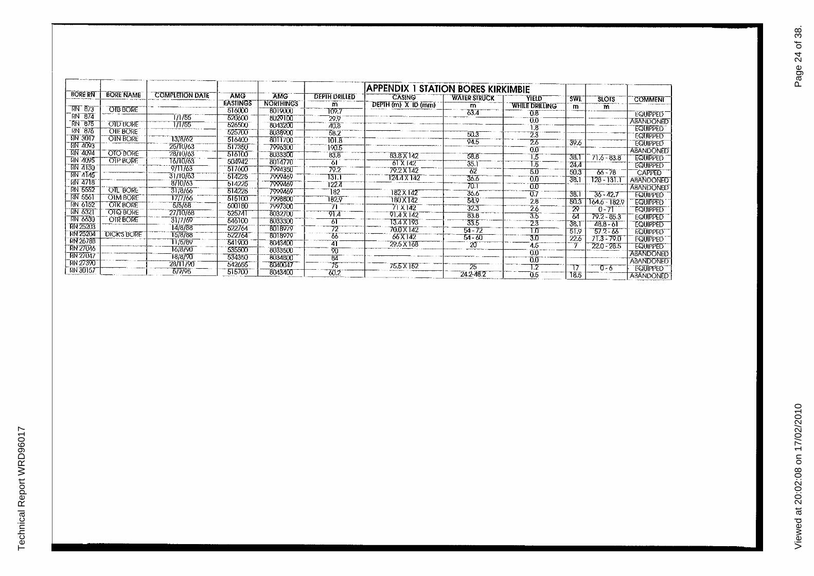
APPENDIXl
STATION BORES
The following table is a list of bores drilled on the station together with selected details about their location, construction and groundwater intersections. More detailed infol1l1ation on many bores is available on request from the Water Resources Division in Darwin. Some of the headings on the table are explained below:
-BORE Ri'l: A registered number assigned to each bore by the Water Resources Division.
-AMG EASTL'IIG The east-west coordinates of the bore in metres. It refers to the grid lines on the map.
-AMG NORTHING The north-south coordinates of the bore in metres. It refers to the grid lines on the map.
-DEPTH DRILLED The total depth of the bore in metres below ground level.
-CASL'IIG The length of casing in the hole in metres and it s internal diameter in millimetres .
-WATER STRUCK The depth in metres below ground level at which the main water bearing zone was encountered.
-YIELD The amount of water obtained in litres per second by airlifting, usually during drilling of the hole.
-S'WL Standing water level, the depth below ground level that water rises to in the bore.
-SLOTS The depths in metres below ground level between which the bore casing is slotted.
Water Resources of Bunda & Kirkimhie

Tec
hnic
al R
epor
t WR
D96
017
Vie
wed
at 2
0:02
:08
on 1
7/02
/201
0P
age
23 o
f 38.
,-------,-- - - - -,---- -'- APPENDIX i STATION BORES BlJNDA -, , "~ 'BOliEliN BoiinrilME - ( OMpL~lloN D7\fEf---,',A, MG- h AMG -PEPTH DRILLED '-- CASING, - --WAl,ER SIR, OCK --- YIELD "If&,,'-~WL
~' -- -- --- - -" - --- '---- EASIINGS - NOill-':"_~~ - -m DEi'jff\m) X ID(mm) -- -- m WH][HIlII, ... ",- iii" m
R, ,N, 800, ~';"', ,I-----, - nUN" llA, BOtlE, - '-, - - 1/1/46" -, 550445, 00?5436 00,.4 - -- - , ,- -8[4 , 2.3,-" --, --ltQUIPfiL IlW1lO, KlNSLleK BOllE -~- -54.1900 0015400 D.l - - - , 63ij~ ().u~ 1'0:.5 - r EQUlR N -002 - ---,-- ~- - -54711)1 OO12ij~" 125 90X 12,- 115.6 2.3 ' - -
IN 803 , MAUbOORt - 533852 79'1997Y- -- -117.1--'- 106.7 l.l --, .~v"'.
-li~n~~-:: : BAOIIANiAilOllf~ 10/5/63 --'- g~ -~~~ -, -~Ir '- ,-- --':'lM 6:g -------:: -', A~~~1'jr - RN :rS'20 - -22 MILE BOllE -- -- 1676/63 '- -~ -7i'965;~- ,Re - -- - 23.8 -, 2.r- 20.7 ~ EQUlpt RlT,j5r, KiRKI~mEBOIIE - _ "110/63 -i53;rn- 005TiJ{j)_' _" 52.7 22.9j{I~"":"", -1[r-___ , 1.5:---=--:", - -_ -....:::-CAPPE
fIN ,457l SANDY CREEKBOilE " 5/10/63 559800 800525U _ 90.8 28.5 x 142 12.2 0.9 , EQU,rrw
lIN ;roos BUNDA WElL - - -~' 0025800 -- 30.5 ' -- 0.0 -- AllANDONED '-1lN5514
n
, ---, 318)M ~?35 0014213 ' , 167.6 - -~ lUX 193 0.0 ---- -AilANDONED -r1N7630 - ---- 475m-- - ~173IT 1\055913 51'.8 '-4.3X 142 21.3 2.5~ - cAPPED
RN 7636-1-- - -- - 3/5/71 -- - 6:;3Y74-00557~ -(if- 20)W2 '-2i[ij '1.9 m.S- - CMpED
,1~N,,7851 "BAU,FlA, N,'AN62IlO,I,'E '- 1016/7,2 - -55Il35u,', 7W,63-,'"OO, ,12,1.<1' 2.2X,,193' 93 12.2 '" U----,.4 - 12.2 - ~,- EQUIPf'§! N 7il5ir ' "-', - - ~/6172 - -534000 8026600 -, 76.2 - - ~- 0.0 - , - - t 1iN9160- - ., "- - " IDITOl)'') 530TW-- 8OO1lOOJ -- -- - 80 "~ --RN20056 f-----:-:GOMHOLEBQiiC 12I1O!!<)" 53~ -OOIOHXl ~- '50 50X 142 ----- 46-:;0 3.2 --:-, ' --"
,1lN 10076 -BoilrMAUD N03 BOllE -- 11/10/79 -~" S35500/~SO -50 --SOx Jif2 ~27 1.5 -34-- , IllfT::>28ii2 "MAODNo200rlE - --I7116il '-52§lOO 7993VOO 0 - ~--MT 7JJ -'14=-$0 HID IRN23Hl1 '" MAIN liOADilO:~", ----TO!6172 ' 528262 00 927jJ' 85.4 24.4 X 142~' 3T~ "EQUIPP~ I I
lIN 23185", - U,INNERCAMPBORE '1)1769", 559W2 0041762' --- 83.8 42.7 X 142- -- 73.2 4.5 - _' 69-CA,PPI, """""'6---' MIMAYEilBoilE-- -1/11/69 MY??!)- 0031742 - '-- 63 -S9.6XI42 ' -'O 0.9 --- 'EQUIPPE
:n: '~'TfIDVL"VtdCCIIJ7"\f'\"'---- ",,-j,,"7ITF'" - "'.-"0''''';'- B0179U) .-. -~8(j nn -- ... ,i"~j~-,rr,-W/CI4Y - -0011561 ~ 0 -.
NIFFlYSBOIIE -- '12/l2J"M -- -5'19102 - 8tT87i11, W- -WX152, 'SZ:',65,C3.iJ '"I r-'--',-E@IPf'W PEAilTREE BDRE -~13m/65 -547161 0012390-- 35 ' --0.4-- l - -[~-
! RN2473'r-MAIN ROAD BORENo. 1 '-26/8186 - 528900 8011l5OO 135 5X203 - 67' 0.7 ~, , -i liN 2.4738 'MAIN IlOAD IlOIIENo'. 2 27/8/iJ6 -528900-- 001 iJ500 - --- 90 3 x 203 -" - 0.0 I 'O,'O ••• " ••
RN24759 -~ORllAN BollE 30/8186 - 50::100 0041278" - - 80 '80,5 X 142 47 2.0,m-00 min",,<,,-~~~K - -MANLY BOllE - - -,2)!/~!: ~ --=(..~;£d -=-~l.9~~ --, -'-l~O ---00.5X,142 63-}~' -- - 62..' IIIB'ANOO
RN 2/391 MOONRULlllORE ' '27711790 - 635250 8tmiOO-- 106 I06XH,2-' 98 2.0 '--"'-. 4 _ 106 '!!".."Z~ '--GOREYBQrllO--- 2116N1-, 543560-- 8001072 -- 00 - -', 8O.5Xl:;O 80 4.0 --34:6 62~74 I.....;~:;,; RN27661- caES BDI1E 'n ' -, 22/6/91' ,-, _(;45128 -8027~,,---, ",3 - -73.5Xl5tI..._ 47 '~.O 39 ' 55-67" _EQUIPf'E[j-RN U 54 3D/8/95 559 '< 8tll4200 61 ABAfJDONED !]I!! ~15S - ,-, " 30/8/95- 5&>200 0026?5U 3QAilAIDONGIY
-RN &flo(' '-- GoV8mMENT1lOilE- - ,. ___ 519/95 ~ 63B789 - - oo2<1:!ZO, - 120.2- --ri'lJ.ox 146 _90.2-1~2 -1.2 76:5- 9-, CAWEI)
Tec
hnic
al R
epor
t WR
D96
017
Vie
wed
at 2
0:02
:08
on 1
7/02
/201
0P
age
24 o
f 38.
-- - -- -.-._... - ---- -_.-- ---APPENDIX 1 STATION BORES KIRKIMBIE
hORER BORrNAME COMPLETlONllAl[- - -AMG AMGu DEPTH DRillED CASiNG- WAfER STRUCK -- VIEW ,~ -SWL sLOfS- --COMMENT I 1----- - - -~ - - - -EAS!l!!';!S NORfHlNCf . m -l)EPfH (m) ,no (mm) m - ---WHILE DRILLING -"'-. m - ---.-
llf<1l7:l-01U80RE -- ~- 61&XlO 8019UXJ -~- 10?.? -- - . 63.4 -0.8 - -- EQOIPPW--RN-874 -- - 111/55 520600 --'=100 '29.'1- ---- -- ----u:o - ABANlJONrn I Rir875 OiDElOT, . 11755- 5265!Xf8O<lE22 4U.8 - ---.- 1.8 --- EQUIPPED
-Rfl--S7 OlE BORE- ~ - -525)(iJ 803lWOO 58.2-- OO.::r- 2.3 ---- -~-EQ"OT RN30fl 01N BOllE -- - -1318/62 016400 801110C _101.8 ._ - -~ - 94.5 2.6 - --39.6 I---EQUi.. "" -filTLi1l9r-' '. 257f0l63 517350- 7996300 - -- 190.5 - - - . 0:0 .-. --. ABANDoNED ff~_ -OT01JOTIE. 28/10163----:----= .. 5.1 00 -8033""l83.8· 83.8X_141 _-il8.8:.:..... -IT __ 1_38.1 --nr83.8 .E 01 PED' N ~U9 OIPB0!lE 16/10/63 -504 42 8014770 61 61 X 142 _ 35.1 1.5 _2~.4 [QUIPPED
RlT4l30-- . ------9/11/63 517~ 7994350 79.2 - 79.2XI4:;>-·- 62 5.0 --5<13 IX-/8 CAPPED
!' ilT41) - - '--'--311111/63 - - 5f4225 7 469 131.1 -124.4 X 142'- - - 36.6 0.0+~8:r 123-131.1 - ABANOOfll'l) -RI'I47li!'-- -- 87T0763 51,,:?')l, l'i99469 -122.4- 70.1 0.0 --. ~--RN5552 --OILBGRE 3 7fJi6l)- 5 42'25 -7 182 ra2X 1~ -36.6 0.7 - 36,( "" _ 42.1 "~V" • W
- RN 6" 01M80RC - 17/7/66--- SI511Xl -7~8800 -182:9- iOOX142 54.9 - 2:-8 - - t).3 TM.6"lllZ.9 EQUIPPHl 'IN-I>Ts2 KBGRr' 5/6/68 - . 5OOliJO -- 7wT300 71-··· 71X142- -32.3 .. 2.6-- - 0''7,- . mUIPPw'
f632I-· 010 BOI<E . 27/10/68 ----52SZ~_! 00327CXJ' 91.4 91.4)(142- 83.U~· 3.5 - ~- ... 79.2 -lJ5r - EQ= RN-6630--0TRIlOJ!E . ----31m/,Q -- 546100 - 61 13.4X193 33.5 2.3-- 38T 48.8-61 ,QUIP, RN252(13 --- -1478/88 5~27&r 80169/9 - 72 70.0 X 142 54-72 1.0 0l.9 5/_2-66 EQUfPPHJ RN25204 olc~S1KH . T5T87B8- 5:mor !Jffi1l979- . 66 66X142 64-60 3.0·22.6 71.3-79.0 WUIPPED-
----- 54]9CO ----8W3i100 '--~in' ~29:5X-168 - ---4.5 ''1- -ry'ftf' <: 7\1iir~nr,.,. .
-0033500 . ~ .- .. _.. -0.0-·
5343§2.. 80341lOJJ. Il4 0.0"· r~l 2n/ffiru .. 542655· . iJ04OO47 . ~ -'7& 7S.5X 152 25 -_. 1.2 . ·17-------0:-0 i-IlNlll157 -I. _519195 . I 515700· -80434iXJ.. ·----60.1-24.2-;f81...... - .. ~O.5 .. __ Kti ~ .... ~~,_
N 21 .---

Technical Report WRD96017
Viewed at 20:02:08 on 17/02/2010 Page 25 of 38.
APPENDIX 2
CHE1\UCAL ANALYSES OF GROUND WATERS
The following table lists chemical analyses performed on ground waters on Bunda and Kirkimbie. See Appendix 3 for an explanation of the main factors which limit water use for stock and domestic consumption.
Water Resources of Bunda & Kirkimbie

Technical Report WRD96017
Viewed at 20:02:08 on 17/02/2010 Page 26 of 38.
I! :N IX 2 CHEMICAL ANALYSES OF GROUNDWATERS BUNDA
z a:
4741 275' 7,91 18, 6' 221 201 21 1431 o. 1~=~ 6~.~21_1 ~~1 ~~
• 410i 230, 8.5 17: 3 21 32 22 6 2031 0.1 0.41 16: 184 ~o ~ " ~ _255 7.1 ~1~1 46 19, 4 255 1 I 24 209
~~ ~ ~ 7.4 ~;~ 95 ~~~I 3~ ;'53 I ~ ~~ 1 2300 :1§§Q 7.2 18C 30C 5< I ~71'-----'-~~
1080 110 7.4 84 5 91 130 14 : 18 I I I 764 7.8 1281 8 20 I 121 149 I I 190
707 474 7. 201 6, 3 46' 621 166 0.41 1 I 2721 200 I I 75CI 540: 7.4 ' I 34 261 641 4: 351 0.61 0.8 '288 19C I I I 490: 7.8 91 7, 36 241 60! 53 329 0.6' 0.2 270 188
II.,':!': '~IIII' ~;Z' ~~~~ ~:~I ~~: I '~' 15~: ~~I 1!~; 6 I 1~~! ~:;' 0.11 I ~~i ~;! 10 ' I 7., I 6 24 7< I ! 290, 0.1 2:
, 10 I 05 28 ~ 6511 1 600" 8. 34 I 3
480: 339 ',3 26, ! 3161 6 72 I 2051 • 800 49CI 7.5 1151 8 22 78 4 3021 1.4 248 1291
12105173' 860· 520 7.8, 120 9 24 20 81 53 31S1 0.5 0.3 259 142 051731 860 520 8,1, 125 9 24 20 85 56, 315, 0.4 0.11 258 142
t ;10 8.1, 14:3. 9 1 17 82 541 300' 0.4 0.71 246 98! ;50 I =Ii 24 91 _,06 566 ~O, 275 l' 22, 6631 430 10 951 i 195! ! ,0.3' 3, I ~
14201 24: l' I 01 1951 . " 665 2560 15301 3121 I 1: '--'.' 01 24. 4 1< 4211 ~ 26001 1610 7.6 395' 76i' 549 21, I ~ 2690 1 1810. 7.5 413 11 961 72 650 ~'389 1.3! 0.1 319' 535 3920 2390 7.21 4831 20 14: I 147 820 294 673 0.3' 4.5 '552: 963
960' 70! 81 4, 11 5: I 65 81 56 418 0,2: ' 343, 405 950 7CI 7.2: 3EI 7f: 53 61, 38 468 . 0.2 1 '384 412 920 251 7.2 3E: 8: 52 611 431 473' 1, 0.15 2C 388 419
186 ~ I 900 60' 47' 70 54' 401 22 527, i 0.3 O. 4331 396' 182 li'~' 7. 7'1 ,110 651 1771 91' 462 1C 0,28 O. 5 3791 542.
IRN2, ,7: 1 15' 6. 581 1 ~69 46 65' 351 470 1 .J1.19 O. 6 385 3621 08/95: 10, 4 . . 8161 _24C 140f 9' 444 9 O.4~ 1".6 3641 J~I
I .1£j.. 7~: , ~ 03351
I 071~' 692l=i "-W- 1;' . ~ 5 ! 2C 821' I 689 447 7, 75 42 421 21 C Be' 212 : 27111/90 35C 200 7.8 23 17 19 I 2: l' 56 1 1.3 . 1281 109
376 6.6 22 lei 29; 2: 3, 1 I 0.6 2" 45 142 I 1358 7 136, 71' 212 10 6 C I 4' I ill 358 121/09195 14081 7.8 155' 90i, 2' , 14, =! 5.8 : 6 I '151 405 2~ 1336 '.7 1611 551 351 2591 6f 21 I 31 281
156 1610019 778' 4 '.5 201 91! 501 " 8' ~1' 21 13, 156 '669, 11.2 231 1, 39 50' : 3C ~ 3 ," I 03

Technical Report WRD96017
Viewed at 20:02:08 on 17/02/2010 Page 27 of 38.
APPENDIX 2 CHEMICAL ANALYSES OF GROUNDWATERS KIRKIMBIE'
z a:
, "I I I ~I I~' 1 I~ E'
," ~'E"_E. ~ i, ~ i E '"
I~ ~ i f ~ ~ g 'I t I" ItS I ~ Iii; g
~ I'~'= ~ ;: i.~~ ,i~ ~ ~ ~.al ?,i:; ;:" ,ii5 ~ : ~~ ~ 86 741 7,5 8 3,31 2' 14 12 0.11 1 I 20 16 I RN8~: v....L,-O:: i070676il i ! 65 50i 6.3 5 11 4 21 6 4 2: 0.4 14.2 1 22 2C
~ ~ : 5~ 360 7.7 6' 8 31 2C 32 20 ~ 0.3 0.2 '~ 16C 8e 51: 7.5 49 5, 18 67 108 201 O. 0.1 I ! 324
i 950 640 7.4 68 6 90 41 144, 50 ~2rl 0041 O. I~ ~ ~. 830 520 7.41 60 6 70 351 821 43 354: J.5I 0.6 ,2901 319
: 483 299 7.5 41, 6.6 5 40' 381 10 1261 0.31 O. 206 178 '~~ 40CI 240' 7, 341 4 26: 20 3C Ie, 207 1 0.4 170 148 RN87~ 12111/81 450 2701 7,2 361 6 27, 20 30 14 212 ,0.4 0.5 174 147
RN3017 RN3017
17
15/11185 410 2801 6.8: 34 4 251 19, ~ 15 199 0.4 0.1 ....i.§.....1.±1. , 500 7.6 ,250 262 1 666 383 7.5 24 6.4: 41 58 28 153 O. 1.8 250 346
! 70~ :::1 -i ~ ~;~; ~ 1~ ~;~ I 6:~! I~ ;~~ 1 121~8' 6B 9.'.ICl~I~,ln
( 520 3301 7.81 73 71 32 20] 36 1 I 0,3, 0.1 '2 170
IRN4718 i ~~~~ ;:~; 6,~1-fs& ;; ~:7~i ~~: 2~ '5 o.~! 6:4 8e ~
'~,323CI19n 7. ~ 331 43 130 740 240 168 0.7i 2.6 276..§§Q I L.\Jl/u~foo'323C:1972: 7. o~o 33' 43' 130 74C 240 168 0.7 2.6 12761 650
, 1451 1301 6.9 4 6 6 4 lC 2 66 0.4 5.2 541 28 ~ ~ 1745 6, 43: 37 72 .92 678! 305 2971 4 0.6 2.4 141.2441.2§.§l
II I: 567 323 6, 171 5 53 35 lSi 18 366 1 0,21 4,6 151 30e' 276 R~' 152 1 ; 1 ~ I I 4 1 ~
I~L;~ '~ : ;: I i ';61 I , I ' Iili ~ 275 6.5' 30, 81 15 16 5' ...!.§.~i 9, 0.1. 2: 68 S' 103
~ • 15i08i691 510' . 7.1 40 t-3"oo-'+-':::..:.;..----=+---""'t-;.2;';"·17:;J--71~68 1RN6630 i i 490' 340 7.6 45 4 28 24 30 13 258 0.3 0.5 I 212 168 ~3 14/~I~OI 7.6 i 3024 150 J 123,2000 IRN25203 1: I 424 259 6,2 17 5 35 24 22 18 2281 2 0.1 2.8 2CI 1871 186 ~ 43C 7,5
' I 28' 195 I I , 16C, 168
L~lJ?5/11/891 910 560 7.8: 641 6 49 .62 24! 2' 579 0.6: • 475 377 1Rf\l26788' 05/11/89 83CI 510: 7,8 6CI 3! 351 631 2C; 191 543! I 0,51 0.8 445 346
I 434 3561 8 82 171 1 18 24 259 O. 212. 88

Technical Report WRD96017
Viewed at 20:02:08 on 17/02/2010 Page 28 of 38.
APPENDIX 3
WATER OUALITY REOUIRElVIENTS FOR STOCK AND DOIVIESTIC WATER
1. WATER QUALITY STANDARDS FOR STOCK USE
SUBSTAl'iCE
pH range Total dissolved solids Sodium chloride
Sulphate Nitrate Fluoride Magnesium
GUIDELINE VALUE
5.5 - 9.0 8000 mg/L
Not more than 75% when total dissolved solids near limit.
2000mg/L 400mg/L 5.0mg/L 300mg/L
The composition of mineral supplements to stock feed must be considered when stock waters are near to the guideline limits. especially for fluoride and sulphate. Further information is available from the Chief Veterinary Officer, Northern Territory Department of Primary Industry and Fisheries.
2. WATER QUALITY STANDARDS FOR DOIVIESTIC USE (NATIONAL HEALTH AND MEDICAL RESEARCH COUNCIL, Al'1D AUSTRALIAN WATER RESOURCES COUNCIL CRITERIA)
Analyses of water intended for human consumption should lie within the guidelines listed below. Discussion relating to the quality of domestic water should be addressed to the Northern Territory Department of Health and Community Services.
SUBST Al'1CE
pH range Total dissolved solids Chloride Sulphate Nitrate Fluoride Hardness (as Calcium Carbonate) Sodium
GUIDELIl'<E VALLE
6.5 - 8.5 1000mg/L 400mg/L 400mg/L 4Smg/L 0.5 - 1.7mg/L 500mg/L 300mg/L

Technical Report WRD96017
Viewed at 20:02:08 on 17/02/2010 Page 29 of 38.
APPENDIX 4 PUMPING TEST RESULTS
The results of pumping tests earned out on bores on Riveren are summarised in the following table. More detailed information is available from the Water Resources Division in Darwin.
RN BORE PUMP PUMP BORE SW"L(m) NAME RATE SETTING(m) DIAyIETER
(Lis) (mml
801 Kinslick 3 70 147 73.5
7636 0.5 24 152 15.8
27391 Moonbull 3 90 140 83.4
27660 Gorey 5 45 147 34.6
30156 1 92 147 76.7
PUMP RATE -The recOIrunended pump rate in litres per second
PUMP SETTING -The recommended depth below ground level at which the pump intake should be set
BORE DIAi\1ETER -The minimum internal bore diameter in millimetres
SWL -The standing water level in the bore, in metres below ground level, measured immediately prior to the test
Water Resources oj Bunda & Kirkimbie

Technical Report WRD96017
Viewed at 20:02:08 on 17/02/2010 Page 30 of 38.
APPENDIX 5
DAMS AND W ATERHOLES ON BUNDA AND KIRKIMBIE STATIONS
BUNDA
1. Lewis Dam: This is a typical drainage-line excavated tanle Located in a stud paddock, it is fenced and serves 100 head of cattle, Water consumption is not regular so it normally lasts till the end of dry, If supply were restricted from April to September reliability could be improved, During this period 100 head could be supplied with 85% reliability, The turkey nest has more than sufficient capacity to cater for 200 head over a ten day period. At the time of inspection the turkey nest was full and was leaking. There was no overflow pipe. It would be desirable to direct any overflow back to the tank. Any deepening of the tank would depend on the suitability of the subsoil. The inlet channel needs a clean out.
2. Doyles Dam: This is a drainage-line tank which is fenced and has a turkey nest and windmill to regulate the supply.Though it fills every year, it only lasts until September, because it is relatively shallow. Three hundred head are supplied daily immediately after the wet, however the numbers reduce to 100 head by August. Some 100 to 150 head could be watered from April to August on a daily basis, with 75% reliability. Any deepening of the tank would depend on the suitability of the subsoil. Maintenance of catch drains would enhance the tank's reliability .
KIRKINIDIE
I. Highway Dam: This is a drainage-line tank which fIlls almost every year but is usually dry by July. Cattle water directly from the tank. It supplies 1000 head soon after the wet, but
Water Resources of Bunda & Kirkimbie
the supply reduces to 200 head by July. The depth of water in the tank at full supply level is about 1.7m, and hence only lasts till August. Eight hundred head could be watered in April, 400 in May, and 200 in June with 70% reliability. Any deepening of the tank would depend on the suitability of the subsoil.
2. Yellow Waterhole Dam: Yellow waterhole dam is an excavated waterhole surrounded by bunds with an inlet structure, similar to an onstream tank. The inlet structure is damaged and the bund around it has been scoured, however the inlet pipe is intact and is still operational. The tank is fenced with an adjoining windmill and a ground steel tank. H fills every year and usually lasts till September. Water ponds upstream of the tank providing additional (shallow) storage. Water is pumped from there into the tank from time to time when the tank water starts to deplete. The tank supplies 800 head of cattle soon after the wet but the supplies reduces to less than 200 in August. It could cater for 200 head from April to September on a daily basis with 80% reliability.
3.0TMDam: This is a drainage-line tank which fills every year and usually lasts till September. Even without any stock usage, the water will not last till the end of December because the tank is too shallow. Cattle drink directly from the tank. About 800 head use the tank soon after the wet but reduces to 100 by August with a reliability of 60% for this decreasing demand. Stock water supply from April to August on a daily basis for 200 head would result in a reliability of 80%. The tank benefits from both the catchment sheet flow and creek flow. In order to make the supply last to the end of the Dry the tank needs to be expanded and deepened subject to subsoil suitability. An inlet channel that feed into the tank needs desilting.

Technical Report WRD96017
Viewed at 20:02:08 on 17/02/2010 Page 31 of 38.
4. Maud Dam: Maud dam fills every year, and dries by September. It is a shallow onstream lank and cattle drink directly from the tank. Soon after the wet it supplies SOO head of cattle, but the numbers reduce to 100 by August. It could supply 400 head in April and 200 head in May with a reliability of 80% or 200 head on a daily basis, from April to July with 75% reliability.
5. Nigger Dam: This is an excavated tank located on a broad shallow watercourse on a black soil plain. It is fenced, and water is regulated through a turkey nest and a windmill. It fills eight out of ten years. Four hundred head are watered after the Wet but by the end of September it dries up. It is capable of watering 400 head from April till September, with 76% reliability. Any further deepening of the tank would depend on the suitability of the subsoil.
Water Resources of Bunda & Kirkimbie

Technical Report WRD96017
Viewed at 20:02:08 on 17/02/2010 Page 32 of 38.
APPENDIX 6
SITE INVESTIGATIONS
Having determined a catchment capable of supplying stock quality water for the required stock numbers, site investigations must be undertaken to confmn that the proposed tank site is suitable. The site investigation guidelines presented here are based on a very useful booklet entitled "Design and Construction of Small Earth Dams" (Nelson, 1985, Inkarta Press, Melbourne). The key investigation method is to auger a series of investigation holes. In an excavated tank situation this helps to:
• determine the extent of impermeable soils and the presence of any layers which are likely to have leakage problems
• show if there is any impermeable and soft rock present, such as rippable shale • ascertain whether shallow groundwater is present, and if so, is it suitable for stock • provide information on the soils to ensure the tank sides will be stable
If an onstream tank is proposed then spillway conditions will also require investigation.1f it is too sandy it will erode and wash away or if it is in rock, excavation could be very expensive.
A hand operated 100 rnm earth auger capable of drilling to between 5 and 6 metres is the basic tool for the subsurface investigations. Auger holes are sunk in soil to one metre deeper than the tank design depth, with minimum 500 gram samples taken wherever there is a change in soil. A plan of the soil changes down each hole should be kept to compare variations from hole to hole. Excavated tanks reqnire a minimum five test holes, one in the centre and the other 4 positioned at the mid point of each corner slope of the proposed tank (Figure 6). For the modification of an existing waterhole, auger holes are sunk at 50 metres apart along the centre of the bed, and 100 metres apart along the edges of the bed. The site for proposed excavation must fulfil three main conditions: • the loss by seepage must be relatively low • the sides must be stable • silting must not be excessive
1. Seepage Loss
In most areas of the plains country the watertable will be deeper than the proposed 4 to 4.5 metre tank depth. Hence leakage of stored water through the sides and base of the tank is possible. A simple permeability test can give an indication of potential Jeakage from the tank using the series of auger holes used for soil sampling. The following procedure is proposed but is onI y indicative: I. Pre-soak each hole for at least I hour before starting the test by fIlling the hole to exactly
0.5 metres below ground level and maintaining it at this level by addition of water. 2. The test involves maintaining this water level (0.5 metres below ground level). The
amount of water added to keep the water level is recorded. Continue the test for one day.
If the water added exceeds 30 Iitres per hour, then the site is too permeable for an excavated tank. If it is between 3 and 30 litres per hour then the area should be considered as doubtful and should only be accepted with professional advice. Rates less than 3 litres per hour indicate that leakage will not be a serious problem.
Water Resources of Bunda & Kirkimbie

Technical Report WRD96017
Viewed at 20:02:08 on 17/02/2010 Page 33 of 38.
TH5
TH2
.I1J31/1onQiwvrr.Jrp,dgn
o TH1
o TH1 , TEST HOLE No 1 le'el
TEST HOLE PLAN FOR AN EXCAVATED TANK
TH4
TH3
Fig 8

Technical Report WRD96017
Viewed at 20:02:08 on 17/02/2010 Page 34 of 38.
2. Tests on Soil Samples
Soils commonly consist of particles which may range in size from coarse gravels, through sands and silts, to very fme clays. Gravels and sands can be readily identified by appearance and feel and unless they are mixed with fmer silts and clays will be prone to leakage. Clays and silts are indistinguishable when dry. While clay is one of the most useful soils in dam building, silt, when wet, is the most troublesome. It tends to be unstable in the presence of water, often collapsing when saturated.
Generally a favourable site investigation result will confirm the presence of non-dispersive clays that bind together any coarser particles to create a water holding material. Accurate classifications of soil types can be undertaken by sending at least 100 gram of sample to the Department of Lands Planning and Environment and these provide a very good indication of soil suitability. However simple field tests can give a good feel for the likely behaviour of the soils.
1. A simple test to differentiate clay from silt is to moisten the sample and feel it. Clay should be sticky. Pinch a sample between the thwnb and forefmger; if it is clay it should be possible to form a flexible ribbon about 1.5 mm thick and at least 40 mm long.
If the presence of clay is established then the water holding potential of the soil can be tested using the "bottle test". The bottom of a 1.25 ml plastic drink bottle is cut off. The bottle is inverted and one-third filled with the soil to be tested. The bottle is filled with water. If no water seeps through the soil in 24 hours, it has good water-holding properties.
3. All clays should be tested for dispersion. Some clays break down in water to form a suspension of clay particles throughout the water. This is dispersion and has been the cause of many dam failures. To test for dispersion take 5 to 10 grams of air dried soil crumbs and drop them into 100 ml of distilled water in a cup. Allow it to stand for at least one hour without shaking. If the water appears cloudy then dispersion has occurred and special care will be needed if building tanks in these materials. The presence of deep erosion gullies suggests markedly dispersive soils and these sites should be avoided.
If site investigations show that there is likely to be problems with any of these factors then professional advice should be sought, and remedial measures may be possible. However it may be necessary to abandon the proposed site
Water Resources of Bunda & Kirkimbie

Technical Report WRD96017
Viewed at 20:02:08 on 17/02/2010 Page 35 of 38.
APPENDIX 7
CONSTRUCTION DETAILS OF EXCA V A TED TANKS. TURKEY NESTS AND MODIF1ED W A TERHOLES
Assuming preliminary investigations (Appendix 6) have shown the suitability of a site for a specific structure then construction can be begin. No matter how good the design, poor construction methods can lead to a less than perfect structure.
I. Excavated Tanks The site is first cleared of vegetation and the planned tank laid out on the ground using marker pegs. Excavation is commonly carried out using scrapers or bulldozers. If the tank is in an area with some slope (say greater than 1 in 100) excavated material can be used to construct bunds around three sides of the excavation to increase its storage capacity. The bund should have a minimum berm width of 5 metres (Figure 6). Topsoil with potential for leakage must be removed down to an impervious layer before the bund is built, and compaction should be undertaken using the available machinery. The ideal time to achieve optimum compaction is early in the Dry when soils are still slightly moist.
Three sides of the tank are excavated with a slope of I in 3, and flow enters the tank through the side with a mild slope, as low as of 1 in 10. The inflow side may be rubble packed to prevent erosion. Where the excavation is in rock, with little chance of erosion, the inlet batter may be increased to 1 in 4, to decrease the volume of material to be removed. The recommended slopes allow for machinery to enter the tank, excavate, tum and exit with ease. For offstream excavated tanks catch drains can be constructed, ego using a tilted grader blade, to direct an increased volume of sheet flow towards the tank.
2. Turkey Nests The current design and construction techniques for turkey nests are adequate although special attention should be paid to:
• removal of leaky topsoil from the base before construction; • the selection of a non - dispersive soil construction material
(Appendix 6); compaction at optimum moisture content. This can be achieved if construction is undertaken early in the Dry while soil is still moist. Every 100 mm layer of loose soil should be compacted.
For three days water supply from a turkey nest the following dimensions are recommended:
NUMBER OF CATTLE INl\'ER DIAMETER INNER DIAJvlETER HEIGHT AT BASE (metres) AT TOP (metres) (metres)
200 6 13 1.1
500 8 16 1.5
These figures are based on sides with a 1 in 2.5 slope.
Water Resources of Bunda & Kirkimbie

Technical Report WRD96017
Viewed at 20:02:08 on 17/02/2010 Page 36 of 38.
3. Modifying Waterholes Modifying a waterhole usually means constructing a narrow excavated tank within the waterhole to increase its storage capacity. Site investigations are critical. If the subsoil is impermeable, non-dispersive, and there is no rock \\ithin two metres depth then excavation should be possible using a scraper. The presence of rock will usually require the use of rippers for excavation. The longitudinal batter could be 1 in 3 or less, while the cross sectional batter should not be more than I in 2.
Water Resources of Bunda & Kirkimbie

Technical Report WRD96017
Viewed at 20:02:08 on 17/02/2010 Page 37 of 38.
AQUIFER
BATTER
BE~\1
BORE
BUND
DEMAl\'D
APPENDIX 8
GLOSSARY
A body ofrock that is sufficiently permeable to conduct groundwater and to yield economically significant quantities to bores and springs.
Slope expressed as a ratio of horizontal to vertical distance.
Flat area between excavated area of tank and bund.
Small diameter hole constructed with a drilling rig, and down which a pump is lowered to extract groundwater.
Bank, constructed of compacted fill, used to contain water.
The volumetric flow rate required for stock watering, therefore the rate at which water would be supplied if available.
DRAL~AGE -LINE TANK Excavated tank built in an area which does not have a defmed creek.
GROUNDWATER Water contained in rock below the water table.
OFFSTREA,VI TANK Excavated tanks built near creeks, and connected to the creek by a channel to tap the creek flow.
ONSTREAM TANK Excavated tanks built across a well defmed stream.
RELIABILITY
SPILLWAY
The frequency at which a tank would be able to supply the annual stock water demand, eg. 90% reliability means that the tank should be able to supply annual stock demand for on average every nine years out of ten.
A structure designed to overflow excess water out of a dam.
Water Resources of Bunda & Kirkimbie

Technical Report WRD96017
Viewed at 20:02:08 on 17/02/2010 Page 38 of 38.
SPILL TAIL CHANNEL A channel built downstream of the spillway to direct excess water back into the creek.
STANDING WATER LEVEL (SWL) The level, below the ground surface, to which groundwater will rise in a bore or well.
STORAGE CAPACITY The volume of water that can be stored in a tank up to its full supply level.
TOTAL DISSOLVED SOLIDS (TDS)
WATERTABLE
A measure of water salinity based on the quantity of solids left after evaporation of a litre of the sample.
The surface resulting when the standing water levels in adjacent bores in the same aquifer are connected.