bumblebee2 stereo vision camera - university of south...
TRANSCRIPT

Bumblebee2 Stereo Vision Camera
Description
We use the Point Grey Bumblebee2 Stereo Vision Camera in this lab section. This stereo camera
can capture 648 x 488 video at 48 FPS.
1) Microlenses
2) Status LED
3) IEEE 1394a cable
4) 12 PIN General Purpose Input/Output
(GPIO) Connector.
Your Task
1. Capture stereo images of a certain object.
2. Manually change disparity range settings to capture disparity images of objects in short distance
and long distance respectively.
Operation steps
1) Run TriclopsDemo. TriclopsDemo allows you to experiment with all of the stereo functionality
provided by the Triclops library. For simply viewing images produced by your stereo vision
camera system, we recommend using FlYCapture.
2) Select camera:
3) Click on the 'Camera Control' button on the application toolbar to modify different camera
parameters such as gain and shutter.
4) Save stereo pair: Save/Load->Save Image ->Raw->Stereo.

5) View disparity image by choosing correspondent item from a drop-down list on the application
toolbar.
6) Click on the 'Stereo Params' button on the application
toolbar to modify a variety of important stereo settings.
Perhaps the most important parameter to set in order to
insure the extraction of good stereo data is the disparity
range. This sets the minimum and maximum distance
over which measurements will be made. The larger the
maximum disparity setting, the closer the minimum
distance measured. The smaller the minimum disparity
setting, the further the maximum distance measured.
The speed of stereo processing is highly dependent on
the disparity range being searched. The larger the
disparity range, the greater the processing requirements.
7) Save disparity image: Save/Load->Save Image-
>Disparity.

NextEngine Desktop 3D Scanner
Description:
We use the NextEngine Desktop 3D Scanner
in this lab section. See scannertech-specs.pdf
1. Lasers.
2. Sensors.
3. Whitelight illuminators.
4. Object in view.
5. AutoDrive
Task:
1) Perform a high definition 360 scans of
an object held in place infront of the
3D scanner.
2) Generate 3D model of an object by
aligning, trimming and fusing resulted
scans.
Instructions
1) Check connections:
a. scanner to a computer with the USB 2.0 cable;
b. scanner to an outlet with the power cable;
c. AutoDrive to the scanner with the attached cord.

2) Prepare object.
If the object is reflective or transparent for a more accurate scan of the
surface it will be better to use a powder prior to scanning. Align the
object on the scanning platform once it prepared.
3) Launch Software (ScanStudio HD) and click ‘Scan’ button.
4) Scan settings. a) Scan style. You can choose one of three modes of scan. “360” will complete a full rotation of
the object, “bracket “ scans 3 angles (you set the angles, described later) and “single” makes
one scan from a fixed angle. Choose “360”. For “360” mode you also have to choose the
number of divisions you want to scan in, this will determine the number of rotations and
individual scans. Choose 4 dimensions for time saving.
b) Resolution. Points/in2 is how many pixels are scanned. The higher resolution the more time
and memory the scan will take. Keep the setting in the middle unless your subject is very
small.
c) Color option. It will be better to choose Neutral, unless it’s very light or dark. If you have a
really dark object or a really light object and have the opposite option checked the laser
won’t pick it up.

d) Range. Depending on the size of your specimen, you can choose the range you want to scan
at. For most objects MACRO is fine. Make sure that the object is the recommended distance
away from the scanner.
e) The time and memory are displayed at the bottom left of the window, based on the settings.
5) Scan. Once you finished with scan settings, click on the green arrow at the top to start the scan. The
scan will happen automatically here. When it is done, the model is viewable on screen.
In some cases (for example, big holes at the top and bottom of your scan) you will need reorient
your specimen and perform second scan operation. In that case do not move the platform in relation
to the scanner, and use the same settings.
6) View. When all scans are done, to rotate them use the left mouse button, to zoom in and out use the
right mouse button or the scroll wheel, and use both buttons to pan.
There are different viewing modes for the completed scan: Textured, Solid, Wireframe, and
Points (View->Display Mode). Textured displays the surface as an image from the camera in
the scanner. Solid displays a surface from the data collected, with shadow but no other
surface detail. Wireframe displays connected edges, and Points shows individual points
making up the model. Also you can adjust the viewing options by clicking on the balls in the
lower right corner of the screen.
7) Trim.
After the scan is complete it is possible to trim unwanted
sections (turntable, holding arm). The arrow will let your adjust the
specimen’s viewpoint, like usual. The circle and square and rectangle allow
you to select areas you want to delete. When you have selected what you
want to cut out, click the icon with scissors.
8) Align.
When the scans are complete program will try to align the model automatically. But sometimes it
doesn’t work properly. In that case you have to
perform manual alignment:
a) Expand the scan family. Pull out all scans but
one.
b) Click on Align and place the colored pins at
identical spots on the different scans. The more pins
and the wider they are spaced out the better. If your
specimen doesn’t have any distinguishing points, you
may want to mark a specific spots by markers before
the scan.
c) When the pins are placed click Attach Scans.
9) Fuse.
When the scans are aligned, you can apply a Fuse operation. This combines the
multiple scans into a single mesh and close off areas that were not visible during
scanning. Click FUSE. Detailed information on available Fuse settings you can find in
the 1). After you’ll finish with Fuse settings click FUSE again.

10) Save model. When you’re finished with your model, click File/Save As and save the file as an SCN file.
Also you can save your model in STL, PLY, OBJ, VRML formats. All of these formats export
triangulated meshes. But there are some differences between them:
a) STL: In an STL is included only Geometry without color information.
b) OBJ: Includes color information by associating the mesh with a series of image files which are
created when you export.
c) PLY: Includes color information within the file itself, meaning there are no additional external
image files. Color is mapped onto the mesh vertices using a red, green and blue value for each
vertex.

Range Processing and 3D Printing
Description:
In this section, we will print the 3D scan that we got from previous section. The whole task step are
as follows.
Task:
1) Perform a high definition 360 scans of an object held in place in front of the 3D scanner
(done in previous section).
2) Generate 3D model of an object by aligning, trimming and fusing resulted scans (done in
previous section).
3) Save the scan in STL format.
4) Submit the 3D scan to be printed.
a. If the scan is good enough to be printed, then we are done.
b. If not, then we have to take more steps to make it printable.
5) If the scan has problems to be printed, we will first take the range image of the scan and then
make a new STL file from the range image.
Instructions
1) Prepare a 3D scan of an object.
This is done as previous section with a medium resolution (Points/in2).
2) Convert to STL.
Save the scan in to an STL file.
3) Look at the scan in STL viewer.
Take a look at the scan in the STL viewer.
4) Check if you think it is printable.
If the scan is printable, then we are done. But usually it is not the case. The scan above, for
example, will certainly fail to be printed. The files that we send to be printed, need to have
no isolated vertices, thin walls, disconnected vertices, etc. As you can see the scan above is
not bounded under the object, because when we were scanning it, not data were collected
from the bottom (and neither from the top) of the object.
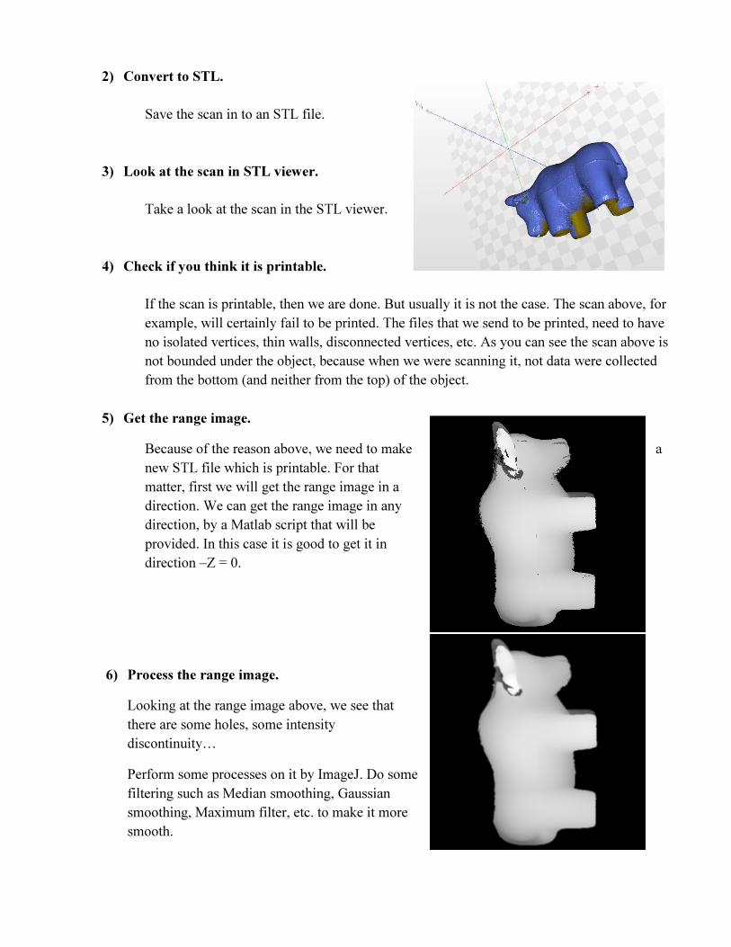
5) Get the range image.
Because of the reason above, we need to make a
new STL file which is printable. For that
matter, first we will get the range image in a
direction. We can get the range image in any
direction, by a Matlab script that will be
provided. In this case it is good to get it in
direction –Z = 0.
6) Process the range image.
Looking at the range image above, we see that
there are some holes, some intensity
discontinuity…
Perform some processes on it by ImageJ. Do some
filtering such as Median smoothing, Gaussian
smoothing, Maximum filter, etc. to make it more
smooth.

7) Make new STL file from the processed range image.
Open the Image to STL converter. This program takes an image as intensity (or range) image and
exports an STL file.
Set “Target Height” at 10-20. Check with both checked and unchecked options for “Invert Output” to
see the difference in STL file. However for the final STL file you should check this option to have a
better print.
8) Look at the new STL file in STL viewer.
The new STL file is not as the previous STL file (that
we had from the 3D scan) though. But it is printable
now and we can print it and check the result.
9) Print the new STL file.
Send the STL file to printer and check the result.

Appendix A.
Contents of the 3D Scanner Box.
Top Layer contents:
Orange Modeling clay,
Test Object,
PowderPen,
PaintPen. (3;2 white,
1red)
Bottom Layer contents:
NextEngine Desktop 3D
Scanner! (left)
AutoDrive turntable,
PartGripper fixture
Power cable,
USB 2.0 cable,
Safety and Compliance
Guide,
Backup Disk (software).

Appendix B.
Links:
1) NextEngine User Manual : http://www.inventionstudio.gatech.edu/wp-
content/uploads/NextEngineManual.pdf
2) Nextengine 3D Scanner Guide (by Joel Russ, University of Illinois at Urbana-
Champaign):http://itg.beckman.illinois.edu/visualization_laboratory/equipment/3Dscanning/
NextEngine/nextengine_3d_scanner_guide.pdf
3) 3D Scanner Tutorial (Clemson University): http://www.cusa-dds.net/3d-scanning/
4) Specifications – scannertech-specs.pdf