bulk modulus capacitor load cells - digital library/67531/metadc703423/m2/1/high_res... · sscl-274...
TRANSCRIPT
'._,. '.\
...
Superconducting Super Collider Labora
SSCL-274
Bulk Modulus Capacitor Load Cells
C. E. Dickey
April 1990
SSCL-274
BULK MODULUS CAPACITOR LOAD CELLS"
C. E. Dickey
Superconducting Super Cullider Laboratory? Accelerator Division
2550 Beckleymeade Avenue Dallas, Texas 75237
April 1990
DISCLAIMER
This report was prepared as an account of work sponsored by an agency of the United States Government. Neither the United States Government nor any agency thereof, nor any of their employees, makes any warranty, express or implied, or assumes any legal liability or responsi- bility for the accuracy, completeness, or usefulness of any information, apparatus, product, or process disclosed, or represents that its use would not infringe privately owned rights. Refer- ence herein to any specific commercial product, process, or service by trade name, trademark, manufacturer, or otherwise does not necessarily constitute or imply its endorsement, recom- mendation, or favoring by the United States Government or any agency thereof. The views and opinions of authors expressed herein do not necessarily state or reflect those of the United States Government or any agency thereof.
*Resented at the International Industrial Symposium
+Operated by the Universities Research Assodiation, March 14-16, 1990.
Contract No. DE-AC02-89ER40486.
+ DlSTRlBUTlON OF THIS ROCUMENT IS UNUMlTED
on the Super Collider, Miami Beach, Florida,
Inc., for the U.S. Department of Energy under

DISCLAIMER
Portions of this document may be illegible in electronic image products. Images are produced from the best available original document.
BULK MODULUS CAPACITOR LOAD CELLS
C. E. Dickey
Superconducting Super Collider Laboratory* 2250 Beckleymeade Avenue Dallas, TX 75237
Abstract: Measurement of forces present at various locations within the SSC Model Dipole collared coil assembly is of great practical interest to development engineers. Of particular interest are the forces between coils at the parting plane and forces that exist between coils and pole pieces. It is also desired to observe these forces under the various conditions that a magnet will experience such as: during the collaring process, post-collaring, under the influence of cryogens, and during field excitation.- A twenty eight thousandths of an inch thick capacitor load cell which utilizes the hydrostatic condition of a stressed plastic dielecmc has been designed. These cells are currently being installed on SSC Model Dipoles. The theory, development, and application of these cells will be discussed.
INTRODUCTION
The development of the SSC Collider Dipole and virtually all superconducting magnet projects worldwide, would be greatly aided by the realization of load measuring instrumentation which could be installed at various locations within superconducting magnet structures. To be of true value, such instrumentation must not perturb the superconducting magnet structure itself. To minimize perturbations, it would be necessary to develop an extremely thin load cell. If a thin, accurate load measuring device could be developed, such a device might also have sigdkant commercial applications.
Operated by the Universities Research Association, Inc., for the U.S. Department of Energy under Contract No. DE-AC02-89ER40486.
*
THEORY OF MODULUS OF ELASTICITY CAPACITOR LOAD CELLS
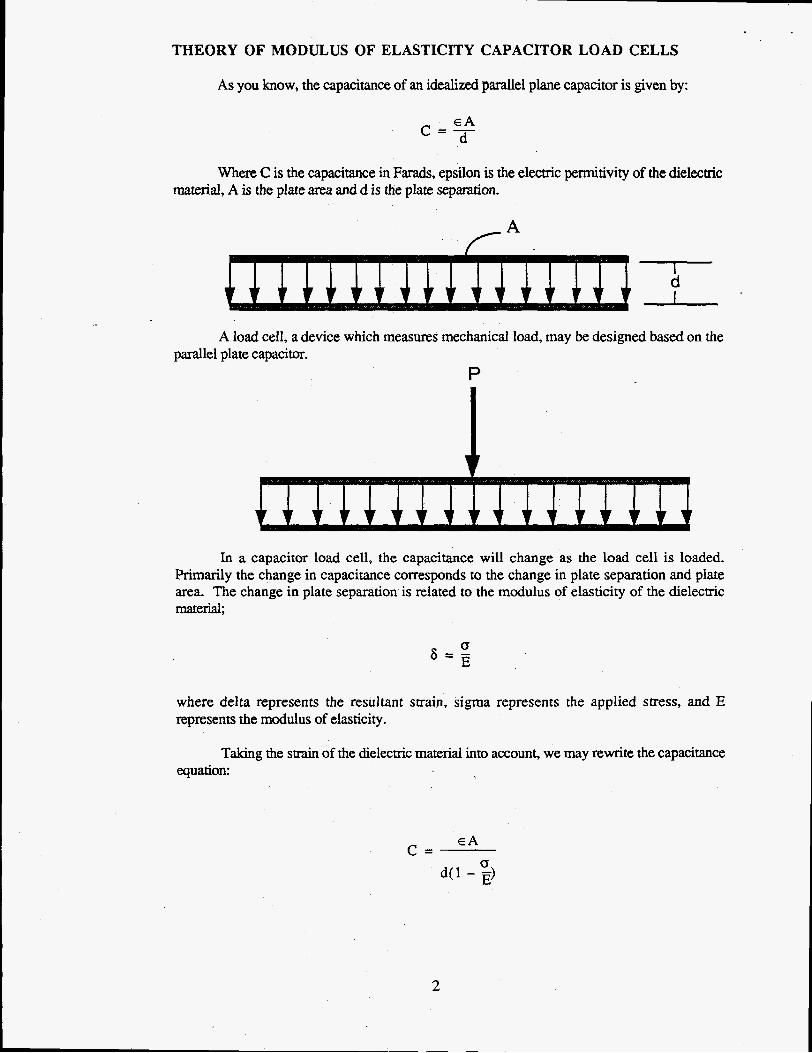
As you know, the capacitance of an idealized parallel plane capacitor is given by:
E A c = - - d
Where C is the capacitance in Farads, epsilon is the electric permitivity of the dielectric material, A is the plate area and d is the plate separation.
d i*
A load cell, a device which measures mechanical load, may be designed based on the parallel plate capacitor.
P
J In a capacitor load cell, the capacitance will change as the load cell is loaded.
Primarily the change in capacitance corresponds to the change in plate separation and plate area. The change in plate separation is related to the modulus of elasticity of the dielecmc material,
where delta represents the resultant strain, sigma represents the applied stress, and E represents the modulus of elasticity.
Taking the strain of the dielectric material into account, we may rewrite the capacitance equation:
E A C =
2
Taking into account the Poisson ratio effect on the plate area;
E A [1+2v "1 d [ 1 -"I C =
Ed
where nu represents Poisson's ratio of the plate material. It should be noted that the load axis strain and the Poisson ratio both tend to increase the capacitance as the gage is loaded. In addition, the above equation does not consider fringe field effects or the possible relationship between applied stress and the electric permitivity of the dielectric material.
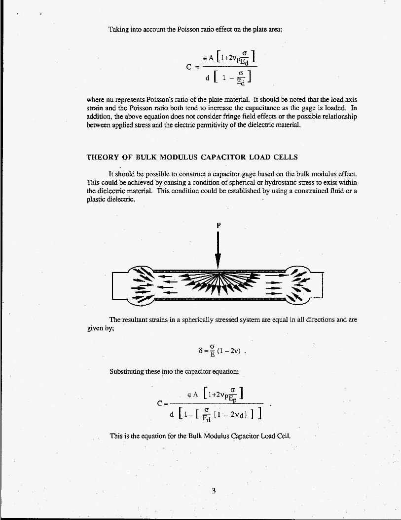
THEORY OF BULK MODULUS CAPACITOR LOAD CELLS
It should be possible to construct a capacitor gage based on the bulk modulus effect. This could be achieved by causing a condition of spherical or hydrostatic stress to exist within the dielecmc material. This condition could be established by using a constrained fluid or a plastic dielecmc.
P
The resultant strains in a spherically stressed system are equal in all directions and are given by;
0 6 = a ( ' - 2 V ) .
Substituting these into the capacitor equation;
E A [1+2vp%] C =
d [ 1- [ E1 - 2Vdl 1 ] This is the equation for the Bulk Modulus Capacitor Load Cell.
3

THEORETICAL DISCUSSION
The equation for the modulus of elasticity capacitance gage is linear up to the elastic limit of the dielectric material where the equation displays a singularity. In fact, experimentation with various dielectric materials has shown that the capacitance continues to increase beyond the elastic limit until the dielectric material fails. However, operation in the dielectric material's plastic region usually results in significant permanent capacitance offset which is no doubt due to plastic flow of the dielectric material.
E A [ 1+2vp$ ] d [ l - % ] Ed
C =
The case of the bulk modulus capacitance gage is somewhat different:
E A [ 1 + 2 v p g ] Q
C= d [I-[ [1 - 2 V d ] ] ] Ed
Here we see that the singularity condition is;
this suggests that the bulk modulus capacitance gage may be able to operate beyond the elastic limit of the dielectric material. Experimentation has shown that bulk modulus gages do indeed operate linearly well beyond the dielectric materials elastic limit.
DEVELOPMENT OF BULK MODULUS CAPACITOR GAGES
Fermilab has been developing the Bulk Modulus Gage over the past year. During this time, we have achieved a more thorough understanding of the gage's properties. In addition, we have gone far toward developing the readback electronics and making the gage's more convenient and reliable to use.
Our initial work was conducted with a classic parallel plate configuration. Since our gage's displayed fairly low capacitance, on the order of a few hundred picofarads, we noticed a significant signal contribution due to the existence of an external shunt capacitance circuit.
4
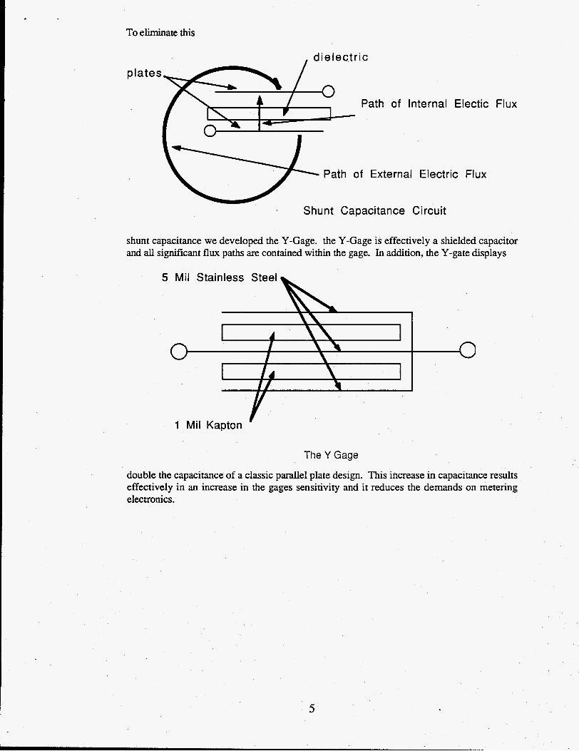
To eliminate this
, dielectric plate
Flux Path of Internal Electic
a 1- I- I \ Path of External Electric Flux m -
. Shunt Capacitance Circuit
shunt capacitance we developed the Y-Gage. the Y-Gage is effectively a shielded capacitor and all significant flux paths are contained within the gage. In addition, the Y-gate displays
6 5 Mil Stainless Steel
1 m
I 1
I / I I1 I
1 Mil Kapton
The Y Gage
double the capacitance of a classic parallel plate design. This increase in capacitance results effectively in an increase in the gages sensitivity and it reduces the demands on metering electronics.

Gage physical dimensions have varied somewhat. But typical dimensions are approximately 1.5 -2" x 0.375" x 0.028". One of the significant advantages of this type of load cell is that its physical dimensions can be easily varied to match the specific case geometry. Curved surfaces or even thinner load cells are probably possible with careful development.
The electronic design of the metering circuit has undergone development and we now feel that we have a reliable and linear circuit.
20w
0
6
Linear performance of the metering circuit is quite important. With a linear circuit, we have the oppormniry to merely adjust gain to calibrate the circuit to the individual gage. This should eliminate the necessity of using the same individual electronics channel for reading a specific gage throughout the various phases of the gage's life. However, it may be necessary to measure and record circuit gain after calibration. Another advantage of using a linear circuit is the elimination of uncertainties caused by the combination of the various nonlinear subcircuit transfer characteristics. Researchers will be presented with the opportunity of studying the load cell directly. Looking at the circuit transfer plot, it should be noted that the point where the plot goes horizontal corresponds to the onset of clipping in the final gain stage of the circuit.
Data from "Cap Circuit 111"
* O w I
a
0 1000 2000 3000
Capacitance (pF)

Figure 1 is a chart recorder output of a typical Bulk Modulus Capacitor Load Cell which has been loaded and unloaded ten times. Its repeatability appears acceptable for the purpose of making quantitative measurements within a collared coil assembly. However, these measurements were made in a fixture. The load cell was not removed from the fixture between cycles. Changes in output which result from repositioning the load cell are currently under study.
Clearly, two areas should be carefully considered. First, thought should be given to the possibility of alternative methods of construction. Precision machining, vapor deposition of the dielectric material onto the plates, and packaging should all be carefully considered. Second, thought should be given to the interface between the magnet and the load cell. These interfaces should be precisely formed and uniform from interface to interface. This does not seem impossible since the coil surfaces are filled with an epoxy layer.
8 Mil SS + 2 Mil Kapton Loaded 1 Ox Repeatability Check
TlP-00933 O.SV/inch Cap meter
CONCLUSION
Bulk Modulus Capacitor Load Cells are apparently a new type of transducer technology. They offer the possibility of providing instrumentation to study superconducting magnet structures. In addition, important commercial applications are possible. However, more work needs to be done.
7