building the largest common-rail...
TRANSCRIPT
— 1 — © Wärtsilä Corporation, May 2004
Kaspar AeberliDirector, Marketing & Sales Support, Ship Power
Wärtsilä Switzerland Ltd, Winterthur
* This is a revised version of the paper presented at The Motor Ship Marine Propulsion Conference, Amsterdam, April 2004.
Building The Largest Common-Rail Engines*
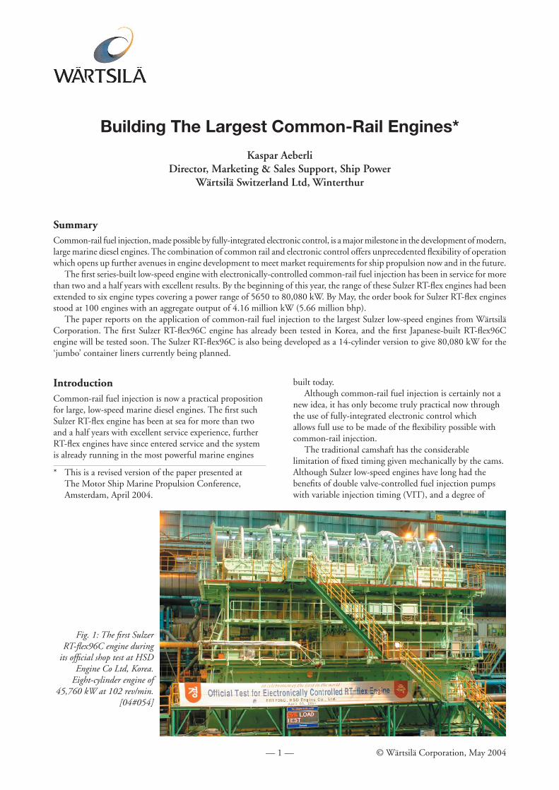
Fig. 1: The fi rst Sulzer RT-fl ex96C engine during
its offi cial shop test at HSD Engine Co Ltd, Korea.
Eight-cylinder engine of 45,760 kW at 102 rev/min.
[04#054]
SummaryCommon-rail fuel injection, made possible by fully-integrated electronic control, is a major milestone in the development of modern, large marine diesel engines. The combination of common rail and electronic control offers unprecedented fl exibility of operation which opens up further avenues in engine development to meet market requirements for ship propulsion now and in the future.
The fi rst series-built low-speed engine with electronically-controlled common-rail fuel injection has been in service for more than two and a half years with excellent results. By the beginning of this year, the range of these Sulzer RT-fl ex engines had been extended to six engine types covering a power range of 5650 to 80,080 kW. By May, the order book for Sulzer RT-fl ex engines stood at 100 engines with an aggregate output of 4.16 million kW (5.66 million bhp).
The paper reports on the application of common-rail fuel injection to the largest Sulzer low-speed engines from Wärtsilä Corporation. The fi rst Sulzer RT-fl ex96C engine has already been tested in Korea, and the fi rst Japanese-built RT-fl ex96C engine will be tested soon. The Sulzer RT-fl ex96C is also being developed as a 14-cylinder version to give 80,080 kW for the ‘jumbo’ container liners currently being planned.
IntroductionCommon-rail fuel injection is now a practical proposition for large, low-speed marine diesel engines. The fi rst such Sulzer RT-fl ex engine has been at sea for more than two and a half years with excellent service experience, further RT-fl ex engines have since entered service and the system is already running in the most powerful marine engines
built today.Although common-rail fuel injection is certainly not a
new idea, it has only become truly practical now through the use of fully-integrated electronic control which allows full use to be made of the fl exibility possible with common-rail injection.
The traditional camshaft has the considerable limitation of fi xed timing given mechanically by the cams. Although Sulzer low-speed engines have long had the benefi ts of double valve-controlled fuel injection pumps with variable injection timing (VIT), and a degree of
— 2 — © Wärtsilä Corporation, May 2004
variable exhaust valve timing being achieved hydraulically in the VEC system, the variation in timing so obtained has been very limited.
The change to electronically-controlled common-rail systems has been made to ensure that the timing, rate and pressure of fuel injection and the exhaust valve operation are fully controllable, allowing patterns of operation which cannot be achieved by purely mechanical systems.
The common-rail concept was adopted because it has the advantage that the functions of pumping and injection control are separated. This allows a straightforward approach to the mechanical and hydraulic aspects of the design, with a steady generation of fuel oil supply at the desired pressure ready for injection. The common-rail concept also has the unique advantage that it allows the fuel injection valves to be individually controlled.
Usually there are three fuel injection valves in each cylinder cover, and in the Sulzer RT-fl ex engines they are operated mostly in unison but under certain circumstances they are operated separately for optimum combustion performance.
The common-rail concept thus provides an ideal basis for the application of a fully-integrated electronic control. The combined fl exibilities of common rail and electronic control provide improved low-speed operation, engine acceleration, balance between cylinders, load control, and longer times between overhauls. They also ensure better combustion at all operating speeds and loads, giving benefi ts in lower fuel consumption and lower exhaust emissions in terms of both smokeless operation at all operating speeds and less NOX emissions. Engine diagnostics are built into the system, improving engine
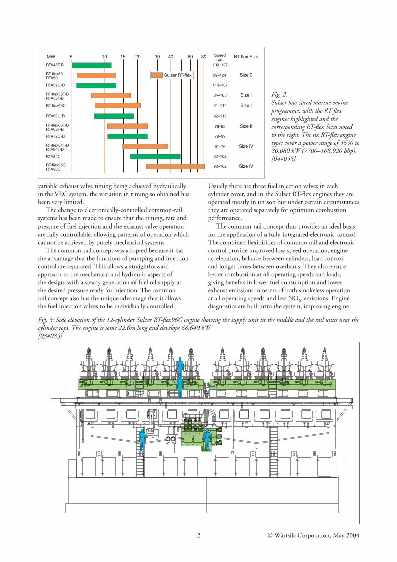
Fig. 2:Sulzer low-speed marine engine programme, with the RT-fl ex engines highlighted and the corresponding RT-fl ex Sizes noted to the right. The six RT-fl ex engine types cover a power range of 5650 to 80,080 kW (7700–108,920 bhp).[04#055]
Fig. 3: Side elevation of the 12-cylinder Sulzer RT-fl ex96C engine showing the supply unit in the middle and the rail units near the cylinder tops. The engine is some 22.6m long and develops 68,640 kW.[03#085]
RTA48T-B
RTA52U-B
RTA84C
RTA72U-B
RT-flex68T-BRTA68T-B
RTA62U-B
RT-flex60C
RT-flex58T-BRTA58T-B
RT-flex50RTA50
RT-flex96CRTA96C
RT-flex84T-DRTA84T-D
102–127
110–137
82–102
79–99
76–95
92–115
91–114
84–105
99–124
92–102
61–76
Speedrpm
5 15 20 30 40 60 80MW
Sulzer RT-flex
RT-flex Size
Size 0
Size IV
Size IV
Size II
Size I
Size I
10
— 3 — © Wärtsilä Corporation, May 2004
monitoring and reliability.As the common-rail system is built specifi cally for
reliable operation on heavy fuel oil, it detracts nothing from the well-established economy of low-speed marine diesel engines but rather opens up new possibilities for even better economy, ease of operation, reliability, times between overhauls and lower exhaust emissions.
It is ten years since development of the Sulzer RT-fl ex common-rail system began, and more than 20 years since the fi rst tests were made with electronically-controlled fuel injection in Winterthur, Switzerland.
The early camshaftless systems developed for Sulzer engines used individual, hydraulically-operated fuel injection pumps. However the change in injection concept from the individual, hydraulically-operated fuel injection pumps to a common-rail system in 1993 was made because the system with individual pumps did not offer potential for further technological development despite it having integral electronic control. Electronic control was found to be insuffi cient by itself, a new fuel injection concept was recognised as essential. Common rail was seen as the road ahead and it is applied in Sulzer RT-fl ex engines.
To summarise, common rail is seen to qualify as the way ahead for the further development of low-speed marine engines because:• The technical concept is well founded• Reliability is becoming well proven – fi rst engine
exceeding 15,000 running hours• More engines are already in service• Sulzer RT-fl ex engines are available for your projects
today – with powers of 5650–80,080 kW• Market demand is clear – already confi rmed orders for
100 engines• Benefi ts available today are worthwhile with the current
execution• Future potential exists for continuing development.
Market SuccessSulzer RT-fl ex engines have been extremely well received by shipowners. The research engine and the fi rst series-built engine attracted their interest right from the outset. The good service experience with the fi rst series-built engine was closely followed by orders for RT-fl ex engines. Ordering, however, took off with the recent order boom for very large container liners. The announcement of the RT-fl ex version of the successful RTA96C engine in this market was most timely.
By May 2004, a total of 100 Sulzer RT-fl ex engines had been built or were on order, aggregating 4.16 million kW (5.66 million bhp), see Table 1.
The concept has been extended to other Sulzer low-speed engine types (Fig. 2). The Sulzer RT-fl ex58T-B and RT-fl ex60C are now in service. The fi rst RT-fl ex96C engine was recently tested. This is the largest engine ever built with common-rail injection. The RT-fl ex96C is also being developed in a 14-cylinder version to give 80,080 kW (108,920 bhp) for ‘jumbo’ container liners. The RT-fl ex84T-D is specifi cally for ULCCs and VLCCs, and
the RT-fl ex68T-B is also included. The smallest RT-fl ex engine is the new RT-fl ex50 currently under development which extends the range down to 5650 kW (7700 bhp).
With the increasing numbers of RT-fl ex engines being ordered, their manufacture is also being extended to more factories. So far, they have been, or will be manufactured in seven factories in four countries; namely Wärtsilä’s own factory at Trieste, Italy, and six licensees in Korea, Japan and China PRC.
Of the 59 RT-fl ex96C engines ordered (Table 1), ten are due to be tested in 2004 of which three will enter service in ships also in this year.
Common Rail for the RT-fl ex96CThe Sulzer RT-fl ex common-rail system has already been described in previous technical papers and articles [1, 2, 3]. Thus the emphasis here is on the system as developed for the Sulzer RT-fl ex96C engines with a maximum continuous output of 5720 kW/cylinder at 102 rev/min.
The hardware in the RT-fl ex system is being developed in four principal sizes (Table 1). The engines already in service, of the RT-fl ex58T-B and RT-fl ex60C types, are equipped with RT-fl ex Size I systems. The next developed is the RT-fl ex Size IV system which is suitable for engines with cylinder bores of 84–96 cm.
In the Sulzer RT-fl ex engine, various mechanical parts, the camshaft and its gear drive, the complete fuel injection pump units including the exhaust valve actuator pumps and reversing servomotors, and all their related mechanical control gear, are replaced by four principal elements: the rail unit along the side of the cylinders, the supply unit on
Table 1: Numbers of Sulzer RT-fl ex engines delivered or on order by May 2004
Type Cylinder No. No. Engines
RT-fl ex96C 12 31 10 10 8 14 7 4 sub-total 59
RT-fl ex84T-D 7 3 sub-total 3
RT-fl ex68T-B 6 2 sub-total 2
RT-fl ex60C 9 3 7 14 sub-total 17
RT-fl ex58T-B 7 10 6 3 5 2 sub-total 15
RT-fl ex50 6 4 sub-total 4
Total 100
— 4 — © Wärtsilä Corporation, May 2004
the side of the engine, a fi lter unit for the servo oil, and the integrated electronic control system (Fig. 3).
Rail unit
The rail unit (Figs. 4, 5 and 6) houses three common-rail systems for heated fuel oil at pressures up to 1000 bar, servo oil and control oil, both at a pressure of 200 bar. It is located at the engine’s top platform level, and has good maintenance access. The starting air is effectively a fourth common rail but it is outside the rail unit for better accessibility.
The Size IV rail unit comprises two sections according to the position of the mid gear drive in the engine. The size of the rail unit enables the electronic units to be mounted on the front for easy access from the engine’s top gallery.
Whereas the RT-fl ex Size I has a modular high-pressure pipe for the fuel rail, the Size IV has a single-piece rail pipe to shorten assembly time and to simplify manufacture. A
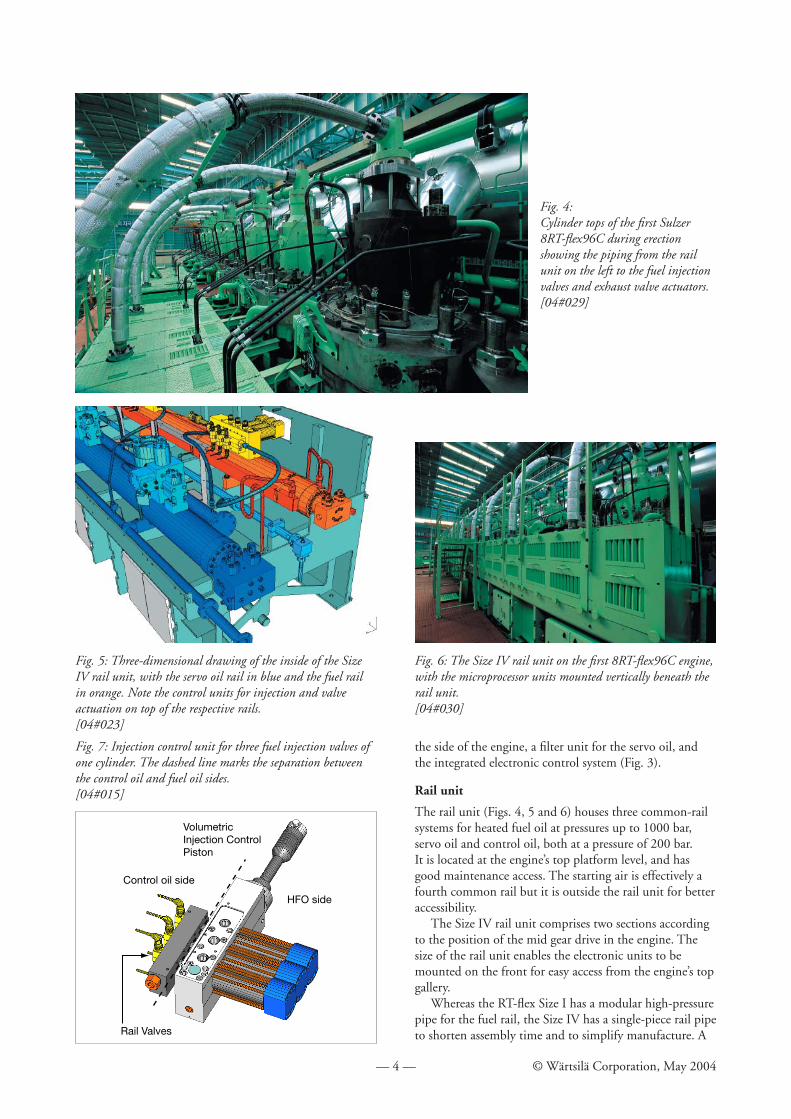
Fig. 4:Cylinder tops of the fi rst Sulzer 8RT-fl ex96C during erection showing the piping from the rail unit on the left to the fuel injection valves and exhaust valve actuators.[04#029]
Fig. 5: Three-dimensional drawing of the inside of the Size IV rail unit, with the servo oil rail in blue and the fuel rail in orange. Note the control units for injection and valve actuation on top of the respective rails.[04#023]
Fig. 6: The Size IV rail unit on the fi rst 8RT-fl ex96C engine, with the microprocessor units mounted vertically beneath the rail unit.[04#030]
VolumetricInjection Control Piston
HFO side
Control oil side
Rail Valves
Fig. 7: Injection control unit for three fuel injection valves of one cylinder. The dashed line marks the separation between the control oil and fuel oil sides.[04#015]
— 5 — © Wärtsilä Corporation, May 2004
single length of rail pipe is installed in each section of the rail unit. The only high-pressure pipe fl anges on the Size IV pipe are the end covers.
The timing and quantity of fuel oil delivered to the fuel injectors are regulated by an injection control unit (ICU) for each cylinder (Fig. 7). The actions of the ICU are controlled through Sulzer electro-hydraulic rail valves. The ICU provides for independent control of each fuel injector in the respective engine cylinder. For Size IV, the individual ICU are mounted directly on the rail pipe. The ICU for Size IV is adapted from that in the Size I with the same function principles for integral injection volume fl ow but to suit the greater fl ow volumes involved.
The simplifi cation of the fuel rail, without intermediate fl anges, has allowed the trace heating piping also to be simplifi ed in the Size IV. The trace heating piping and the insulation are both slimmer, allowing easier service access inside the rail unit.
The exhaust valves are operated by a hydraulic ‘push rod’ as in the Sulzer RTA engines with mechanical camshafts. The exhaust valve drive in the RT-fl ex system, however, is powered by fi ne-fi ltered servo oil on the underside of a free-moving actuator piston, with normal system oil above the actuator piston for valve actuation. Thus there is a clear separation of the clean servo oil and the normal system oil, and the exhaust valve hydraulics can therefore be serviced without touching the clean servo
oil circuit. The exhaust valve drive is controlled with the same Sulzer rail valves as are used for the ICU.
Supply unit
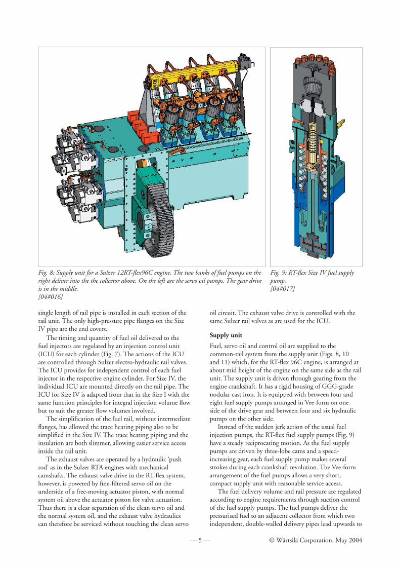
Fuel, servo oil and control oil are supplied to the common-rail system from the supply unit (Figs. 8, 10 and 11) which, for the RT-fl ex 96C engine, is arranged at about mid height of the engine on the same side as the rail unit. The supply unit is driven through gearing from the engine crankshaft. It has a rigid housing of GGG-grade nodular cast iron. It is equipped with between four and eight fuel supply pumps arranged in Vee-form on one side of the drive gear and between four and six hydraulic pumps on the other side.
Instead of the sudden jerk action of the usual fuel injection pumps, the RT-fl ex fuel supply pumps (Fig. 9) have a steady reciprocating motion. As the fuel supply pumps are driven by three-lobe cams and a speed-increasing gear, each fuel supply pump makes several strokes during each crankshaft revolution. The Vee-form arrangement of the fuel pumps allows a very short, compact supply unit with reasonable service access.
The fuel delivery volume and rail pressure are regulated according to engine requirements through suction control of the fuel supply pumps. The fuel pumps deliver the pressurised fuel to an adjacent collector from which two independent, double-walled delivery pipes lead upwards to
Fig. 9: RT-fl ex Size IV fuel supply pump.[04#017]
Fig. 8: Supply unit for a Sulzer 12RT-fl ex96C engine. The two banks of fuel pumps on the right deliver into the the collector above. On the left are the servo oil pumps. The gear drive is in the middle.[04#016]
— 6 — © Wärtsilä Corporation, May 2004
the fuel rail.Servo oil for injection control and exhaust valve
actuation is supplied by the above-mentioned swashplate-type hydraulic pumps also on the supply unit. They are of standard proprietary design and are driven through a step-up gear. The servo oil pressure is controllable. The servo oil is delivered to the hydraulic pumps through a six-micron automatic fi ne fi lter to minimise wear and to prolong component life in the common-rail system.
The Size IV collector for the servo oil is mounted on the supply unit and is connected to the servo oil rail by two independent, double-walled pipes.
Control oil is supplied at a constant, 200 bar pressure by two electrically-driven oil pumps. It involves only a small quantity and uses the same fi ne fi ltered oil as for the servo oil system. The control oil serves as the working medium for all rail valves of the injection control units and the exhaust valve drives. It is also used to prime the servo oil rail at standstill thereby enabling a rapid starting of the engine.
Electronic control
All RT-fl ex functions are governed by the WECS (Wärtsilä Engine Control System) which triggers the corresponding electro-hydraulic rail valves for the respective hydraulic functions. The master input comes from the crank angle sensor which delivers the absolute crank position.
WECS communicates with the ship’s machinery control system by an adapted version of DENIS (the Sulzer Diesel Engine Interface System).
Redundancy and safety considerations
Reliability and safety have had the utmost priority throughout the development and design of the Sulzer RT-fl ex system. Although close attention was given to the reliability of individual items of equipment in the RT-fl ex system, it has to be noted that the common-rail concept affords good reliability and safety because there is inherent
redundancy built into the system.High-pressure fuel and servo-oil delivery pipes, the
electrically-driven control oil pumps, and essential parts of the electronic systems such as crank angle sensors, main controllers, all essential communication interfaces (e.g. CAN-bus cabling) are duplicated for redundancy. The duplicated high-pressure pipes, which are each dimensioned for full fuel fl ow, have stop cocks at both ends to isolate any failed pipe.
The multiple fuel and servo oil supply pumps have adequate redundancy for the engine to deliver full power with one fuel pump and one servo oil pump out of action, and a strictly proportional reduction in power should further pumps be out of action. When pumps in a common-rail system are out of service, the engine output can remain at the maximum possible with the remaining pumps as the available fuel delivery is distributed among all cylinders. This is in contrast to a traditional arrangement of individual pumps for each cylinder, in which any pump failure leads to an imbalance of engine torque which requires a drastic power cut.
Separate control of individual fuel injection nozzles also contributes to safety. In the case of a leaking high-pressure fuel pipe or a malfunctioning injector, only the affected injector needs to be shut off without losing the entire cylinder.
The injection control unit (ICU) prevents the injection of an uncontrolled volume of fuel. Throughout its cycle of operation, there is never any direct hydraulic connection in the ICU between the fuel rail and the injectors. The maximum volume of fuel which can be injected is limited to the contents of the metering cylinder in the ICU. The travel of the metering piston is monitored and if it is excessive, subsequent injections through that ICU are reduced and an engine slow-down activated. If the stroke-measuring sensor fails, the control system switches that ICU to pure time control based on timing of adjacent engine cylinders.
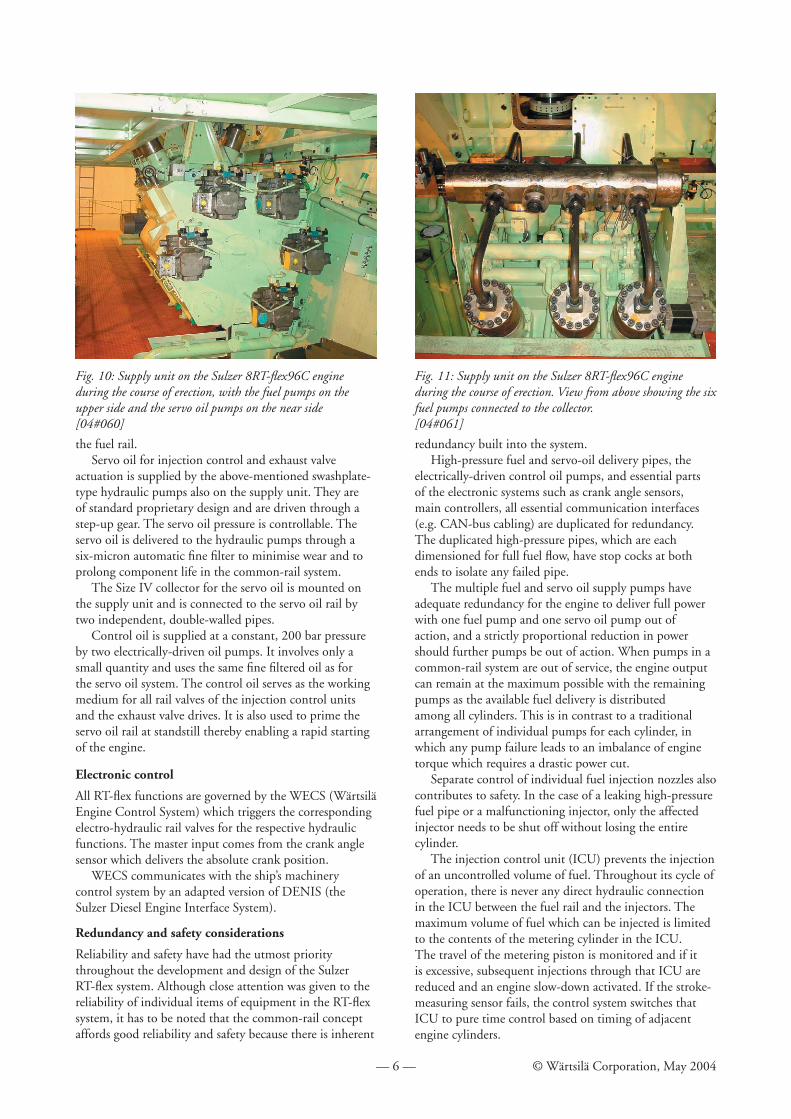
Fig. 10: Supply unit on the Sulzer 8RT-fl ex96C engine during the course of erection, with the fuel pumps on the upper side and the servo oil pumps on the near side [04#060]
Fig. 11: Supply unit on the Sulzer 8RT-fl ex96C engine during the course of erection. View from above showing the six fuel pumps connected to the collector.[04#061]
— 7 — © Wärtsilä Corporation, May 2004
Component testing
An important contribution to reliability comes from the endurance testing of RT-fl ex components before, and in parallel with, engine testing. The endurance testing of Size I components began in 1996. Special test rigs were employed to put all the components through millions of cycles before the fi rst engine tests began in June 1998.
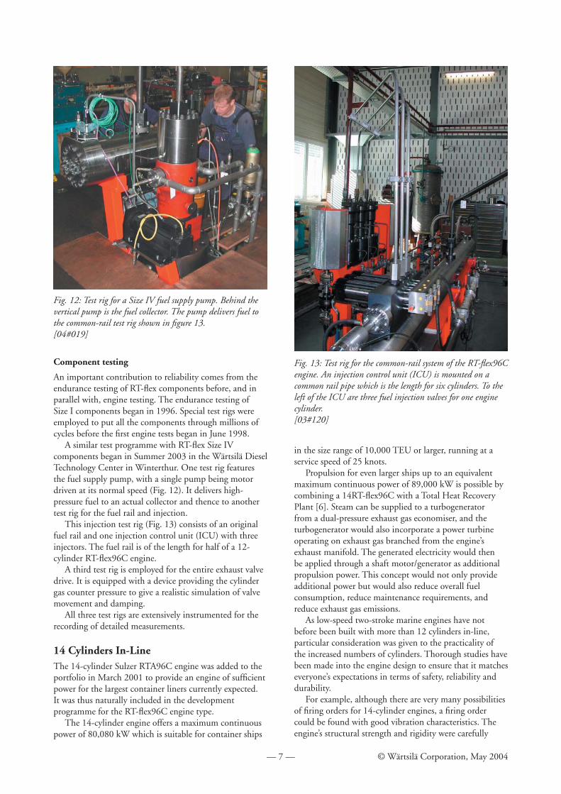
A similar test programme with RT-fl ex Size IV components began in Summer 2003 in the Wärtsilä Diesel Technology Center in Winterthur. One test rig features the fuel supply pump, with a single pump being motor driven at its normal speed (Fig. 12). It delivers high-pressure fuel to an actual collector and thence to another test rig for the fuel rail and injection.
This injection test rig (Fig. 13) consists of an original fuel rail and one injection control unit (ICU) with three injectors. The fuel rail is of the length for half of a 12-cylinder RT-fl ex96C engine.
A third test rig is employed for the entire exhaust valve drive. It is equipped with a device providing the cylinder gas counter pressure to give a realistic simulation of valve movement and damping.
All three test rigs are extensively instrumented for the recording of detailed measurements.
14 Cylinders In-LineThe 14-cylinder Sulzer RTA96C engine was added to the portfolio in March 2001 to provide an engine of suffi cient power for the largest container liners currently expected. It was thus naturally included in the development programme for the RT-fl ex96C engine type.
The 14-cylinder engine offers a maximum continuous power of 80,080 kW which is suitable for container ships
in the size range of 10,000 TEU or larger, running at a service speed of 25 knots.
Propulsion for even larger ships up to an equivalent maximum continuous power of 89,000 kW is possible by combining a 14RT-fl ex96C with a Total Heat Recovery Plant [6]. Steam can be supplied to a turbogenerator from a dual-pressure exhaust gas economiser, and the turbogenerator would also incorporate a power turbine operating on exhaust gas branched from the engine’s exhaust manifold. The generated electricity would then be applied through a shaft motor/generator as additional propulsion power. This concept would not only provide additional power but would also reduce overall fuel consumption, reduce maintenance requirements, and reduce exhaust gas emissions.
As low-speed two-stroke marine engines have not before been built with more than 12 cylinders in-line, particular consideration was given to the practicality of the increased numbers of cylinders. Thorough studies have been made into the engine design to ensure that it matches everyone’s expectations in terms of safety, reliability and durability.
For example, although there are very many possibilities of fi ring orders for 14-cylinder engines, a fi ring order could be found with good vibration characteristics. The engine’s structural strength and rigidity were carefully
Fig. 12: Test rig for a Size IV fuel supply pump. Behind the vertical pump is the fuel collector. The pump delivers fuel to the common-rail test rig shown in fi gure 13.[04#019]
Fig. 13: Test rig for the common-rail system of the RT-fl ex96C engine. An injection control unit (ICU) is mounted on a common rail pipe which is the length for six cylinders. To the left of the ICU are three fuel injection valves for one engine cylinder.[03#120]
— 8 — © Wärtsilä Corporation, May 2004
checked and found to be more than adequate without modifi cation.
Although the crankshaft of the RT-fl ex96C has suffi cient torque capacity for 14 cylinders, the material has been upgraded to enable an increased shrink fi t for a greater design margin. The thrust bearing structure was adapted slightly to cater for the increased thrust.
Adoption of the RT-fl ex common-rail system brings clear benefi ts for the 14-cylinder engine. It avoids any need to consider the design of the longer camshaft and its gear drive. The RT-fl ex system can be neatly arranged with two identical rail units, each for seven cylinders with a central gear drive for the supply unit. Even with a 14-cylinder RT-fl ex96C, the supply unit is still compact compared with the overall size of the engine.
Service ExperienceThe service experience with Sulzer RT-fl ex engines has been very satisfactory. By May 2004, seven RT-fl ex engines had entered service, namely:• The bulk carrier Gypsum Centennial from Korea in
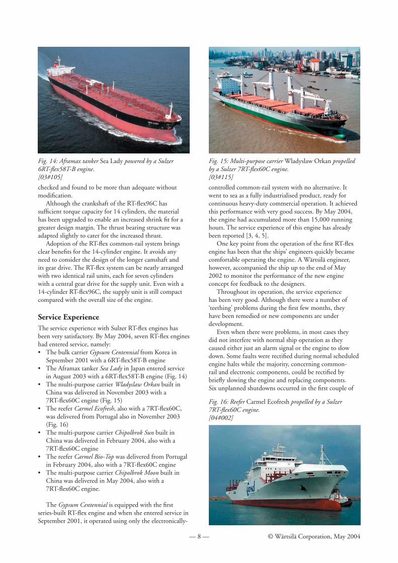
September 2001 with a 6RT-fl ex58T-B engine• The Aframax tanker Sea Lady in Japan entered service
in August 2003 with a 6RT-fl ex58T-B engine (Fig. 14)• The multi-purpose carrier Wladyslaw Orkan built in
China was delivered in November 2003 with a 7RT-fl ex60C engine (Fig. 15)
• The reefer Carmel Ecofresh, also with a 7RT-fl ex60C, was delivered from Portugal also in November 2003 (Fig. 16)
• The multi-purpose carrier Chipolbrok Sun built in China was delivered in February 2004, also with a 7RT-fl ex60C engine
• The reefer Carmel Bio-Top was delivered from Portugal in February 2004, also with a 7RT-fl ex60C engine
• The multi-purpose carrier Chipolbrok Moon built in China was delivered in May 2004, also with a 7RT-fl ex60C engine.
The Gypsum Centennial is equipped with the fi rst series-built RT-fl ex engine and when she entered service in September 2001, it operated using only the electronically-
controlled common-rail system with no alternative. It went to sea as a fully industrialised product, ready for continuous heavy-duty commercial operation. It achieved this performance with very good success. By May 2004, the engine had accumulated more than 15,000 running hours. The service experience of this engine has already been reported [3, 4, 5].
One key point from the operation of the fi rst RT-fl ex engine has been that the ships’ engineers quickly became comfortable operating the engine. A Wärtsilä engineer, however, accompanied the ship up to the end of May 2002 to monitor the performance of the new engine concept for feedback to the designers.
Throughout its operation, the service experience has been very good. Although there were a number of ‘teething’ problems during the fi rst few months, they have been remedied or new components are under development.
Even when there were problems, in most cases they did not interfere with normal ship operation as they caused either just an alarm signal or the engine to slow down. Some faults were rectifi ed during normal scheduled engine halts while the majority, concerning common-rail and electronic components, could be rectifi ed by briefl y slowing the engine and replacing components. Six unplanned shutdowns occurred in the fi rst couple of
Fig. 15: Multi-purpose carrier Wladyslaw Orkan propelled by a Sulzer 7RT-fl ex60C engine.[03#115]
Fig. 16: Reefer Carmel Ecofresh propelled by a Sulzer 7RT-fl ex60C engine.[04#002]
Fig. 14: Aframax tanker Sea Lady powered by a Sulzer 6RT-fl ex58T-B engine.[03#105]
— 9 — © Wärtsilä Corporation, May 2004
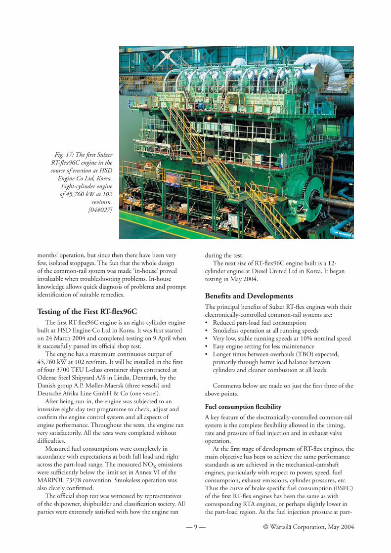
Fig. 17: The fi rst Sulzer RT-fl ex96C engine in the course of erection at HSD
Engine Co Ltd, Korea.Eight-cylinder engine of 45,760 kW at 102
rev/min.[04#027]
months’ operation, but since then there have been very few, isolated stoppages. The fact that the whole design of the common-rail system was made ‘in-house’ proved invaluable when troubleshooting problems. In-house knowledge allows quick diagnosis of problems and prompt identifi cation of suitable remedies.
Testing of the First RT-fl ex96CThe fi rst RT-fl ex96C engine is an eight-cylinder engine
built at HSD Engine Co Ltd in Korea. It was fi rst started on 24 March 2004 and completed testing on 9 April when it successfully passed its offi cial shop test.
The engine has a maximum continuous output of 45,760 kW at 102 rev/min. It will be installed in the fi rst of four 3700 TEU L-class container ships contracted at Odense Steel Shipyard A/S in Lindø, Denmark, by the Danish group A.P. Møller-Maersk (three vessels) and Deutsche Afrika Line GmbH & Co (one vessel).
After being run-in, the engine was subjected to an intensive eight-day test programme to check, adjust and confi rm the engine control system and all aspects of engine performance. Throughout the tests, the engine ran very satisfactorily. All the tests were completed without diffi culties.
Measured fuel consumptions were completely in accordance with expectations at both full load and right across the part-load range. The measured NOX emissions were suffi ciently below the limit set in Annex VI of the MARPOL 73/78 convention. Smokeless operation was also clearly confi rmed.
The offi cial shop test was witnessed by representatives of the shipowner, shipbuilder and classifi cation society. All parties were extremely satisfi ed with how the engine ran
during the test.The next size of RT-fl ex96C engine built is a 12-
cylinder engine at Diesel United Ltd in Korea. It began testing in May 2004.
Benefi ts and DevelopmentsThe principal benefi ts of Sulzer RT-fl ex engines with their electronically-controlled common-rail systems are:• Reduced part-load fuel consumption• Smokeless operation at all running speeds• Very low, stable running speeds at 10% nominal speed• Easy engine setting for less maintenance• Longer times between overhauls (TBO) expected,
primarily through better load balance between cylinders and cleaner combustion at all loads.
Comments below are made on just the fi rst three of the above points.
Fuel consumption fl exibility
A key feature of the electronically-controlled common-rail system is the complete fl exibility allowed in the timing, rate and pressure of fuel injection and in exhaust valve operation.
At the fi rst stage of development of RT-fl ex engines, the main objective has been to achieve the same performance standards as are achieved in the mechanical-camshaft engines, particularly with respect to power, speed, fuel consumption, exhaust emissions, cylinder pressures, etc. Thus the curve of brake specifi c fuel consumption (BSFC) of the fi rst RT-fl ex engines has been the same as with corresponding RTA engines, or perhaps slightly lower in the part-load region. As the fuel injection pressure at part-
— 10 — © Wärtsilä Corporation, May 2004
load is kept higher with the common-rail injection system, combustion is suffi ciently better to have a benefi cial effect on fuel consumption.
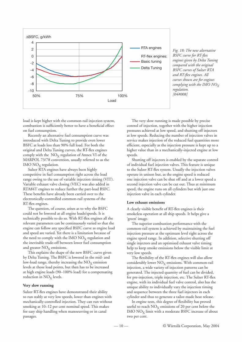
Recently an alternative fuel consumption curve was introduced with Delta Tuning to provide even lower BSFC at loads less than 90% full load. For both the original and Delta Tuning curves, the RT-fl ex engines comply with the NOX regulation of Annex VI of the MARPOL 73/78 convention, usually referred to as the IMO NOX regulation.
Sulzer RTA engines have always been highly competitive in fuel consumption right across the load range owing to the use of variable injection timing (VIT). Variable exhaust valve closing (VEC) was also added in RTA84T engines to reduce further the part-load BSFC. These benefi ts have already been carried over to the electronically-controlled common-rail systems of the RT-fl ex engines.
The question, of course, arises as to why the BSFC could not be lowered at all engine loads/speeds. It is technically possible to do so. With RT-fl ex engines all the relevant parameters can be continuously varied so that the engine can follow any specifi ed BSFC curve as engine load and speed are varied. Yet there is a limitation because of the need to comply with the IMO NOX regulation and the inevitable trade-off between lower fuel consumption and greater NOX emissions.
This explains the shape of the new BSFC curve given by Delta Tuning. The BSFC is lowered in the mid- and low-load range, thereby increasing the NOX emission levels at those load points, but then has to be increased at high engine loads (90–100% load) for a compensating reduction in NOX levels.
Very slow running
Sulzer RT-fl ex engines have demonstrated their ability to run stably at very low speeds, lower than engines with mechanically-controlled injection. They can run without smoking at 10–12 per cent nominal speed. This makes for easy ship handling when manoeuvring or in canal passages.
The very slow running is made possible by precise control of injection, together with the higher injection pressures achieved at low speed, and shutting off injectors at low speeds. Reducing the number of injection valves in service makes injection of the reduced fuel quantities more effi cient, especially as the injection pressure is kept up to a higher value than in a mechanically-injected engine at low speeds.
Shutting off injectors is enabled by the separate control of individual fuel injection valves. This feature is unique to the Sulzer RT-fl ex system. Usually the injection valves operate in unison but, as the engine speed is reduced one injection valve can be shut off and at a lower speed a second injection valve can be cut out. Thus at minimum speed, the engine runs on all cylinders but with just one injection valve in each cylinder.
Low exhaust emissions
A clearly visible benefi t of RT-fl ex engines is their smokeless operation at all ship speeds. It helps give a ‘green’ image.
The superior combustion performance with the common-rail system is achieved by maintaining the fuel injection pressure at the optimum level right across the engine speed range. In addition, selective shutting off single injectors and an optimised exhaust valve timing help to keep smoke emissions below the visible limit at very low speeds.
The fl exibility of the RT-fl ex engines will also allow considerably lower NOX emissions. With common-rail injection, a wide variety of injection patterns can be generated. The injected quantity of fuel can be divided, for pre-injection, triple injection, etc. The Sulzer RT-fl ex engine, with its individual fuel valve control, also has the unique ability to individually vary the injection timing and sequence between the three fuel injectors in each cylinder and thus to generate a tailor-made heat release.
In engine tests, this degree of fl exibility has proved useful to reach NOX emissions of 20 per cent below the IMO NOX limit with a moderate BSFC increase of about two per cent.
Fig. 18: The new alternative BSFC curve for RT-fl ex engines given by Delta Tuning compared with the original BSFC curves of Sulzer RTA and RT-fl ex engines. All curves shown are for engines complying with the IMO NOX regulation.[04#008]
-10
-8
-6
-4
-2
0
2
4
50% 75% 100%Load
RTA engines
RT-flex engines:Basic tuning
Delta Tuning
!BSFC, g/kWh
— 11 — © Wärtsilä Corporation, May 2004
ConclusionCommon rail is now an industrial standard for diesel engines. In this environment, Sulzer RT-fl ex engines have become well accepted by shipowners, particularly in the largest cylinder size, the RT-fl ex96C. Shipowners’ confi dence is being encouraged by the good service experience with the growing number of RT-fl ex engines in service.
With the successful testing of the Sulzer RT-fl ex96C engine, common-rail technology has been proven to be an excellent step forward for all sizes of diesel engines from automotive engines up to the largest low-speed two-stroke engines. For Sulzer RT-fl ex engines, a key virtue of common-rail systems has been that they can be modular with standardised hardware applicable to more than one engine bore size.
The combination of common-rail concepts and fully-integrated electronic control applied in RT-fl ex engines has the best potential for future development. It gives the large degree of fl exibility in engine setting and operation, together with reliability and safety, which are required to meet the challenges in future marine engine applications in terms of emissions control, optimised fuel consumption, insensitivity to fuel quality, ease of use, operational fl exibility, etc.
References1. Stefan Fankhauser and Klaus Heim, ‘The Sulzer
RT-fl ex: Launching the era of common rail on low-speed engines’, CIMAC 2001, Hamburg.
2. Stefan Fankhauser, ‘World’s fi rst common-rail low-speed engine goes to sea’, Wärtsilä, Marine News, No.3-2001, pp12–15.
3. Kaspar Aeberli and John McMillan, ‘Common Rail at Sea: The Sulzer RT-fl ex engine’, The Motor Ship Marine Propulsion Conference 2002, Copenhagen.
4. Konrad Huber and Beat Güttinger, ‘First year of service successful for fi rst Sulzer RT-fl ex’, Wärtsilä, Marine News, No.1-2003, pp4–8.
5. Kaspar Aeberli, ‘Experience with Sulzer Common-Rail Engines’, The Motor Ship Marine Propulsion Conference 2003, Hamburg.
6. Heinrich Schmid, ‘Less emissions through waste heat recovery’, Green Ship Technology Conference, London, April 2004.
7. Rudolf Demmerle and Klaus Heim, ‘The evolution of the Sulzer RT-fl ex common rail system’, CIMAC 2004, Kyoto.