building services specification part three workmanship … · building services specification part...
TRANSCRIPT
Building Services Specification
Part Three – Workmanship and Materials
Smith Consult Limited Mechanical Standard Clauses
Building Services Specification
1PART THREE
PART THREE
WORKMANSHIP AND MATERIALS

Building Services Specification
Part Three – Workmanship and Materials
Smith Consult Limited Mechanical Standard Clauses
Building Services Specification
2PART THREE
AMENDMENT RECORD
Rev Date Description Engineer Approved
01 18/11/12 Issue AS MS

Building Services Specification
Part Three – Workmanship and Materials
Smith Consult Limited Mechanical Standard Clauses
Building Services Specification
3PART THREE
CONTENTS
3.1 GENERAL .............................................................................................................................................. 4
3.2 PIPED SERVICES .................................................................................................................................... 5
3.3 DUCTWORK SERVICES ........................................................................................................................ 18
3.4 THERMAL INSULATION ....................................................................................................................... 25
3.5 HEATING ............................................................................................................................................. 33
3.6 ABOVE GROUND SANITARY PLUMBING AND DRAINAGE INSTALLATION ............................................ 44
3.7 REFRIGERATION PIPEWORK SERVICES ................................................................................................ 50
3.8 PAINTING, POLISHING, CLEANING AND CONTRACT IDENTIFICATION.................................................. 53
3.9 TESTING AND COMMISSIONING ......................................................................................................... 56
3.10 OPERATING AND MAINTENANCE MANUALS ...................................................................................... 60
3.11 RECORD DRAWINGS ........................................................................................................................... 63

Building Services Specification
Part Three – Workmanship and Materials
Smith Consult Limited Mechanical Standard Clauses
Building Services Specification
4PART THREE
3.1 GENERAL
No materials shall be installed that are deleterious to Health and Safety, or to the durability of the
development.
At no point shall Contractors install any, goods, materials, substances or products that are not in
accordance with relevant British Standards and Codes of Practise, CoSHH Regulations or otherwise
generally known within the industry at the time of this specification.
All materials and workmanship shall be in accordance with good building practises current at the time
of installation.

Building Services Specification
Part Three – Workmanship and Materials
Smith Consult Limited Mechanical Standard Clauses
Building Services Specification
5PART THREE
3.2 PIPED SERVICES
3.2.1 GENERAL
All pipework and tubing shall be free from imperfections, cleanly finished, straight, round in cross
section, free from cracks/flaws, laminations and other similar deteriorations.
All cuts from standard lengths of pipe shall have burrs and swarf removed. Pipework ends shall be
trimmed square and thoroughly cleaned before erection.
Care shall be taken to avoid damage to pipe surfaces or malleable fittings through indiscriminate use
of wrenches, vice jaws etc. Any pipework or fittings so damaged shall be replaced.
Pipework shall be installed to the satisfaction of the Engineer. Costs for altering pipework which does
not met this Specification, or the requirements of the Engineer, shall be replaced at the installing
Contractors cost.
Pipework sleeves and fire-stopping shall be installed to meet the approval of Building Control
Inspector and Local Fire Officer.
3.2.2 MATERIALS
All pipework and fittings shall comply with the relevant British Standards, and be suitable for the
environment in which they are to be installed.
3.2.3 INSTALLATION
Exposed pipe runs shall be installed neatly and parallel to adjacent pipes and surrounding building
fabric/structure, wherever practical. Pipework systems shall be routed to set around all columns and
structural projections and shall be set to take up any imperfections within the structural surface. All
vertical pipes shall be plumb unless indicated otherwise. Valves, unions, flanges etc. will be arranged
in an orderly manner.
Due regard must be taken of grading, venting and drainage requirements. The positions of all valves,
drains, supports and fixings will take into consideration routine maintenance requirements. Particular
attention shall be given to the co-ordination of adjacent pipework.
All pipe runs shall be arranged so that the longest length of pipe practicable is used between bends,
tees and flanges or unions. Jointed short lengths of pipe forming a longer straight length will not be
acceptable. Unions must be accessibly positioned enabling the joint to be disconnected.
Pipe work installations shall allow for the application of the full thickness of thermal insulation and its
finish as specified.

Building Services Specification
Part Three – Workmanship and Materials
Smith Consult Limited Mechanical Standard Clauses
Building Services Specification
6PART THREE
Pipework, valves, fittings and equipment forming a system installation shall be erected and locally
supported so that it can be dismantled. It must be accessible for repair and replacement i.e. the
flange, union etc. can be reached, manipulated and worked upon either in the open or else by
removal of a purpose made duct cover, manhole or similar cover.
Pipework passing through walls, floors, ceiling or similar manner shall be complete with flanges or
unions enabling the system to be dismantled as may be necessary. No joints shall be formed within
the thickness of walls, floors or ceilings. Where pipework is contained in floor ducts the installation
shall be completed with a minimum of joints.
Full access shall be provided for concealed pipework having screwed joints to air vents, drain cocks
and pressure gauges to allow the complete inspection, dismantling, removal, replacement and re-
jointing.
Due allowance shall be made in all cases for obtaining full details relating to the skirting heights, sill
heights and floor finishes. Where pipework is visible, off-sets shall only be allowed by prior
agreement.
Pipe clearances shall not be less than:
a. Pipework to pipework - 50mm
b. Pipework to ceiling - 100mm
c. Pipework to floor - 100mm
Bends and off-sets shall be formed by use of an efficient bending machine. Fire sets shall not be
employed. Copper tube may have its bends and off-sets formed with springs or a bending machine.
All changes of direction formed shall be made with a minimum of loss of local wall thickness and the
cross-section diameter shall remain true. Crinkled or scored pipework will not be accepted.
Open ends of all pipework shall be protected. Open ends shall be covered with suitable caps, plugs or
plastic covers. Wood, rag or paper plugs shall not be used. The right is reserved to order the
dismantling and internal cleaning of pipework should these requirements not be observed.
3.2.4 PIPEWORK JOINTING AND FITTINGS
Jointing materials and fittings are to be suitable for the working temperature and pressure of the
system.

Building Services Specification
Part Three – Workmanship and Materials
Smith Consult Limited Mechanical Standard Clauses
Building Services Specification
7PART THREE
The following fittings and joint types shall be provided to facilitate pipework removal for maintenance
purposes:
a. Unions on welded or screwed steel pipework up to 50mm nominal bore
b. Flanges on welded or screwed steel pipework above 50mm nominal bore
c. Unions on copper pipework up to 65mm nominal bore
d. Flanges on copper pipework above 65mm nominal bore
Such fittings shall be provided as a minimum at 12m intervals or as otherwise directed by the
Engineer.
3.2.5 SUPPORTS AND FIXINGS
Pipework shall be properly supported with secure brackets and must permit, where required,
adequate free and/or guided movement due to the operating conditions applicable. Where pipes pass
through structural walls and partitions via sleeves, then these sleeves will not be considered as
supports.
Brackets and supports will be positioned and marked out with care to ensure that they do not
obstruct the access to valves, flanges or fittings requiring maintenance. Supports shall be positioned
adjacent to such pipe fittings and at each change in direction.
Supports shall be positioned in consideration of the position of joints for dismantling purposes such
that the adjoining pipework shall remain adequately supported.
The support of pipework systems from each other shall not generally be permitted without the
Engineer’s express written authority. Pipes shall not be supported from any items of plant or
equipment.
Vertical pipework shall be suitably supported at the base of the riser and at all intermediate levels and
at centres indicated on the above table. Branch circuit pipes shall not be used as a means of support
for the riser main.
Detailed drawings/illustrations of all bracket arrangements shall be submitted to the Engineer for
approval before commencement of manufacture. Pre-fabricated brackets, anchor points, guides and
clamps shall conform generally to the details in BS3974: Parts 1 and 2.
Particular attention shall be given to the co-ordination of combination bracketry.

Building Services Specification
Part Three – Workmanship and Materials
Smith Consult Limited Mechanical Standard Clauses
Building Services Specification
8PART THREE
All pipes exposed to view and generally routed around rooms at floor level shall be supported on long
shank brackets.
Pipe brackets on exposed copper pipework shall be of the cast brass type. Under no circumstances
will brass strip or copper strip type brackets be acceptable.
Brackets on insulated pipework incorporating a vapour seal shall be fitted with spacers and sleeves at
the time of installation. An approved material shall be used between the bracket and pipe surface to
achieve satisfactory vapour sealing.
Contact between dissimilar metals must be avoided. Steel piping shall have steel supporting members
in contact with the pipe. Galvanised piping shall have galvanised contacts. Copper tubing shall be
carried exclusively from contact members constructed from copper alloy, or where mild steel clamp
saddles are used, a lead lining interposed.
Pipework subject to expansion that will cause distortion of hanger type brackets, shall be supported
using roller brackets. Build-in type brackets shall only be used where satisfactory fastening cannot be
attained using surface-fastening techniques.
Building structural steelwork or timber members shall not be drilled either for the passage of pipes or
for the attachment of brackets, nor shall steelwork be welded to, without the Engineers express
written permission.
All fastenings and fixings to the constructional and fabric elements of the building shall be included.
Necessary supports and brackets complete with all bolts, screws and insert or plug fastenings shall be
provided. Softwood plugs will not be permitted. All methods of fixing and fastening shall be purpose
designed and submitted to the Engineer for comment prior to manufacture.
For pre-cast, pre-stressed and hollow floor constructions, metal plate and rod hanger supports with
associated drilling of the structure and secondary spanning steelwork shall be employed.
For hollow wall construction and light partitions, fixing of the spring clip or toggle type shall be used.
Minimum pipework support intervals shall be as table 1.1 below.

Building Services Specification
Part Three – Workmanship and Materials
Smith Consult Limited Mechanical Standard Clauses
Building Services Specification
9PART THREE
Table 1.1
Copper Pipework Support Centres Steel Pipework Support Centres
Bore(mm) Horizontal(m) Vertical (m) Dia. (mm) Horizontal(m) Vertical(m)
15 1.5 2.0 15 2.0 2.5
22 1.5 2.0 20 2.5 2.5
28 1.5 2.0 25 2.5 3.0
35 1.5 2.0 32 2.5 3.0
42 2.0 2.5 40 3.0 3.5
54 2.0 2.5 50 3.5 3.5
67 2.0 2.5 65 3.5 4.0
76 2.5 2.5 80 3.5 4.0
108 2.5 3.0 100 4.0 4.5
For all copper pipework above 108mm diameter the support centres shall not exceed 3.0 metres.
150 4.5 5.0
3.2.6 COVER PLATES
Pipes and tubes passing through walls, floors, ceiling, partitions and false ceilings of occupied rooms
such that the entry/exit is exposed to view shall be fitted with a white plastic cover plate, neatly
installed and secured. Such plates shall be split on the diameter, be snug fit to the pipe concerned
and provided with securing clip or screws.
3.2.7 EXTERNAL UNDERGROUND PIPEWORK
Marker plates shall be fitted to a convenient adjacent structure or special marker post to indicate
position of valves, siphons or purge points. Marker plates shall be in accordance with IMI6.
3.2.8 EXTERNAL UNDERGROUND PIPEWORK - COLD WATER
All cast iron pipework shall be wrapped with bituminous hessian painted with two coats of bitumen.
All plastic pipework shall be installed in accordance with British Standard Code of Practice CP312.
3.2.9 EXTERNAL UNDERGROUND PIPEWORK - GAS SUPPLY
All pipework shall be laid in accordance with the Institution of Gas Engineers' publications and
technical documentation.
Pipework shall not pass under load bearing foundations or load bearing walls/footings. Pipework
routes shall avoid areas where recent infill has occurred. Pipework shall be laid with no less than
750mm of cover under roadways and grass verges and not less than 600mm of cover under paved
footpaths.

Building Services Specification
Part Three – Workmanship and Materials
Smith Consult Limited Mechanical Standard Clauses
Building Services Specification
10PART THREE
3.2.10 UNDERGROUND PIPEWORK - HEATING AND CHWS
Heating and CHWS pipework in a buried underground system shall be installed strictly in accordance
with British Standards and associated Codes of Practice, specifically 4508: Parts 1, 3 and 4 and British
Standard Code of Practice 3009.
Buried pipework shall be sleeved within a proprietary factory fitted corrosion resistant plastic sheath
with the cavity between the service pipe and the outer sheath being filled with an insulating
polyurethane foam with the provision of an air gap where appropriate.
Buried pipework shall be carried out with the minimum of site joints. When the site joints have been
completed the installation shall be hydraulically tested to twice the maximum working pressure of the
installation or 20 bar whichever is the greater, for a period of not less than four hours. After a
satisfactory test, the continuous integrity of the outer casing and insulation shall be made by sealing
each joint with the manufacturer's standard jointing system.
The manufacturer and installer shall accept undivided responsibility for the design, manufacture and
installation of the complete system any underground pipework. The manufacturer's
recommendations concerning the installation shall be strictly followed.
The pipework installation shall be provided with water bars at intervals of not more than twelve
metres and the addition of water bars at each end of the installation.
All existing services which are encountered on the route of the installation shall be fully protected.
3.2.11 TRENCHES AND BACKFILLING
No backfilling shall take place without prior approval.
Details shall be provided by the Contractor for all trenches; this shall include size, depth and method
of backfilling. The number, location, dimensions and loading of all anchor blocks necessary for the
safe working of the installation shall also be detailed.
Details for backfilling shall include:
a. Cold Water - 150mm of pea shingle all around the pipework
b. Gas - 150mm of sand all around the pipework
c. Heating and CHWS - 150mm of pea shingle all around the pipework

Building Services Specification
Part Three – Workmanship and Materials
Smith Consult Limited Mechanical Standard Clauses
Building Services Specification
11PART THREE
3.2.12 MILD STEEL PIPEWORK
All bends, where practicable, shall be formed in the pipe run (i.e. made bends). Where standard
welded fittings are used they shall be of the same quality as the pipe and shall conform to BS1965:
Part 1.
Bends shall be 90oC long radius type.
Branch welding fittings shall be used where the branch is 25mm diameter and above. From branch
sizes below 25mm the sweep may be formed from pipework provided that junction does not restrict
the branch diameter. Where junctions to steel mains are formed by factory or site welding, such work
shall be carried out to conform to BS806. All branch tees where possible shall be formed by the use of
special welded fittings of the same quality as the pipe and shall conform to BS1965: part 1.
Where branch bends are used in lieu of manufactured tees, the profile of the hole shall be removed
from the main run before the branch is welded into position. Branch ends may only be used where
the branch is two or more sizes below the line size. The distance between the centre of two adjacent
branch welds shall not be less than twice the diameter of the larger branch.
Branches shall be made using swept tees or branch bends except where an air lock is liable to form,
i.e. tees on rising mains etc., where square tee shall be used.
Reduction in the line size of any pipework run shall be made using reducing sockets, not bushes.
Reducing fittings on horizontal pipework shall be of the eccentric pattern fixed so as to give a smooth
run to the crown of the pipe. Concentric pattern reducers shall be used on vertical pipework.
Screwed Joints
Screwed joints on steel pipework shall be in accordance with BS21.
All steel pipe having screwed joints shall be carefully reamed out before the plain end is screwed.
When making a joint the screw thread shall be coated with a white compound to BS6956 and hemp,
all surplus jointing compounds being finally cleaned off to leave a surface suitable for painting. The
joint shall be arranged so that on completion a maximum of three threads are left showing.
Should a screwed joint prove defective under subsequent testing, the section of pipework in question
shall be removed and made good.

Building Services Specification
Part Three – Workmanship and Materials
Smith Consult Limited Mechanical Standard Clauses
Building Services Specification
12PART THREE
Welded Joints
Welded Joints shall comply with BS2971 for metal arc-welded joints and BS2640 for oxyacetylene
welded joints. Steel pipe having welded joints shall be prepared for jointing in a manner suitable for
the technique employed.
Pipes shall be prepared for welding with ends sawn or cut off by hand or with flame cut by machine or
flame cut by hand with subsequent truing up by filling or grinding to a level of 37.5o or as may be
required. Welding rods shall in all cases be of good quality copper coated low carbon steel and the
manufacturers shall provide test certificates representative of the rods used.
Screwed joints shall be used where the act of welding would constitute a fire hazard over and above
the normal accepted level. This requirement shall overrule the general recommendations but brought
to the attention of the Engineer at Tender Stage, and in any case before any work proceeds.
Flanged Joints
Flanged joints shall comply with BS4504: Part 3 and shall be prepared to suit the method of
attachment required. Flange pressure ratings shall suit the system and equipment concerned.
Pipes not galvanised shall be provided with flanges screwed or welded for nominal bores of 50mm
and below with flanges welded on for larger sizes. Galvanised pipes shall be provided with galvanised
flanges screwed for nominal bores of 100mm and below, and with flanges welded on prior to
galvanising the pipe for larger sizes, or where specified for all sized galvanised after manufacture.
Where flanges are secured by screwing, the threads on the tube shall be arranged to be just hidden
by the back of the flange and so as not to interfere with the joint. After the flange has been screwed
on, the tube shall be expanded into the flange by a roller expander.
All welded flanges shall be of the slip-on pattern. The pipe end shall finish 3mm behind the machined
face and welded at both this part and at the rear neck of the flange. Appropriate care shall be taken
not to distort the machined face.
Flanges shall be joined with 1.6mm 'full faced' Klingerite gasket with bolts, nuts and washers of
hexagon type. Bolts for BS4504 flanges shall be to BS4190, 400 N/mm2 minimum tensile strength.
The gaskets shall have graphite finish and no jointing paste will be used. All flange bolts shall protrude
an equal distance through the flange of approximately two threads clear of the nut.

Building Services Specification
Part Three – Workmanship and Materials
Smith Consult Limited Mechanical Standard Clauses
Building Services Specification
13PART THREE
3.2.13 COPPER PIPEWORK
Bends shall be formed from proprietary manufacturers’ fittings. Pulled bends shall not be permitted
unless specifically agreed with the Engineer. Similarly branch connections shall be purpose made tees
either square or sweep to suit the application.
Where it is intended to use compression fitting(s), this shall only be allowed for following prior
written approval from the Engineer and the fittings shall be of the type 'B' pattern.
Joints
For capillary fittings, care shall be taken to ensure that the solder used is suitable for the temperature
range at which it is anticipated the system will operate and that the solder is lead free.
All jointing of copper tubes shall be strictly in accordance with the fitting manufacturer's
recommendations.
Excess solder and solder droppings shall be removed on completion of the joint. Particular attention
shall be given to removing surplus flux on completion of the joints. During all jointing operations
using capillary welded and brazing fittings, the fitter/plumber shall be accompanied by a competent
assistant and suitable fireproof mats shall be used to protect the building fabric and decoration. Every
precaution shall be taken to prevent damage by scorching or fire and two portable fire extinguishers
shall be provided for use by the fitters/plumbers in an emergency.
All fittings and jointing materials shall be suitable for the temperature and pressure of the system.
Brazing and bronze welding shall be carried out in accordance with BS1723, BS1724 and the Code of
Practice for Brazing and Bronze Welding Copper Pipework issued by the HVCA.
Where chemical injection is employed for water treatment or for chemical cleaning the system when
commissioning, then the manufacturer's recommendations for materials and jointing shall be sought
and adhered to.
3.2.14 ABS PIPEWORK FITTINGS AND JOINTS
All fittings shall be joined by solvent cement welding utilising Durapipe ABS fittings and materials,
strictly in accordance with the manufacturers’ requirements.
3.2.15 VALVES, COCKS, STRAINERS AND VENTS
All valves shall be of consistent proprietary manufacture and as specified within the technical section
of this Specification. All valves shall be line size. Valve installation and use shall be to BS6683 : 1985.

Building Services Specification
Part Three – Workmanship and Materials
Smith Consult Limited Mechanical Standard Clauses
Building Services Specification
14PART THREE
Safety Valves and Boiler Fittings
Safety valves and boiler fittings shall be provided in accordance with BS759, BS779, BS853, BS855,
BS1123, BS5500 and BS6759.
Safety valves for boilers, heating calorifiers and all pressure vessels shall be provided irrespective of
whether shown on the drawings or not.
Strainers shall be line size with a suitable and approved mesh size/performance. Strainers shall be
suitable for the working pressure of the system to which they are installed.
Strainers shall be flanged on sizes of 65mm and over and shall be provided with drain facilities in the
clean-out connection at the bottom of the body construction. Strainers shall be fitted with isolating
valves upstream and downstream to facilitate maintenance.
3.2.16 TEST POINTS, GAUGES AND THERMOSTAT POCKETS
All temperature gauges shall comply with BS5235, dial type mercury in steel, and shall be polished
with removable brass pockets filled with conductive gel.
All pressure gauges shall comply with BS EN837, shall be complete with siphons and gauge cocks and
shall have 10mm connections. Siphons shall be of the same material as the pipework.
All capillary tubes to remote gauges shall be supported upon their entire length, including the final
connection to the equipment, on PVC coated tray.
In order that the installations may be accurately balanced and set to work, test plug points for
temperatures and pressure tests shall be provided on flow and return connections to all items of
equipment and around mixing valves.
Test plug points shall consist of connections made into the pipework and fitted with a Binder Twinlock
test plug (Binder test points shall not be used on high pressure systems or steam). The test plugs shall
be extended to the surface of any insulation applied to the pipework.
Temperature test pockets shall be located and be of sufficient depth as to ensure a true reading of
the fluid temperature. Where the pipework size is below 42mm the pipework accommodating the
test pockets shall be increased locally to 50mm so as not to affect the flow rate and response of the
gauge/thermostat. Pockets shall be filled with mineral oil and the thermometers fixed so that the tails
are truly subjected to the temperature of the fluid to be measured.
Except where gauges form part of a 'packaged unit' they shall be no less than 100mm diameter for
mounting heights up to two metres from floor level and 150mm diameter above two metres.

Building Services Specification
Part Three – Workmanship and Materials
Smith Consult Limited Mechanical Standard Clauses
Building Services Specification
15PART THREE
3.2.17 EXPANSION AND CONTRACTION
Provision shall be made to install expansion loops formed in the pipe runs by means of long radius
welded bends to the required dimensions. The loops shall be formed in the mains with flanges and
each leg of the loop shall be pulled cold to approximately 50% of the estimated expansion of the leg.
Expansion bellows and joints shall be installed in the pipework as an alternative or addition to
expansion loops with prior permission of the Engineer. They shall be installed in accordance with the
manufacturer’s recommendations.
Provision for expansion and contraction of pipework shall be made of changes in direction and it shall
be ensured that sufficient allowance is made for this.
Branch connections shall be installed with consideration of movement of the main service due to
expansion and contraction.
Mild steel anchors shall be provided to resist the maximum stresses of the pipework. Details of all
anchors, together with loadings and associated builders-work shall be submitted to the engineer for
approval prior to manufacture.
3.2.18 PIPE SLEEVES
In those cases where pipes pass through structural walls, floors, ceilings and footings, sleeves shall be
provided and these shall be installed in a permanent arrangement within the structure.
Sleeves shall in no cases be used as pipe supports, a free equidistant space always being provided.
Puddle flanges shall be provided on pipework passing through walls and intended to be covered by
earth etc., or where passing through bund walls. Sleeves shall be of pipe cuttings properly reamed,
cleaned and trimmed at 90o to bore.
Sleeves in load-bearing walls or footings shall be cast iron pipe. Sleeves in non-load bearing walls,
floors, ceiling and partitions shall be in copper or mild steel or high impact plastic appropriate to the
particular pipe material.
Inside diameter of sleeves shall be not less than 12mm larger than the outside diameter of the pipe,
except where pipes pass through load-bearing walls or footings where sleeves shall be 100mm larger
than the outside diameter of the pipe.
The space between the pipe enclosed and its sleeve shall be caulked with fire stop and intumescent
mastic seal on each side of the sleeve. Alternatively a proprietary sealing system shall be used which

Building Services Specification
Part Three – Workmanship and Materials
Smith Consult Limited Mechanical Standard Clauses
Building Services Specification
16PART THREE
has been shown by test to maintain the fire resistance of the structure and which has been approved
by the Building Inspector.
Flashing sleeves shall be provided as required except where indicated otherwise. They shall
incorporate an integral flange to which a flashing shield can be clamped or welded. The shield will be
built into the membranes and the space between the sleeve and pipe shall be filled with mineral wool
fire stopping and finished externally with intumescent mastic compound.
Sleeves shall normally be finished flush with the faces of the structure through which they penetrate,
the exception being where it is necessary to avoid water spillage draining through a sleeve to the
space below. In this case a projection of 150mm is required.
Cold water and chilled water pipework shall be provided with sleeves of sufficient bore so as to allow
both thermal insulation and vapour seal to be maintained and pass through the bore without
restriction.
3.2.19 VIBRATION ISOLATION AND NOISE INSULATION OF PIPEWORK INSTALLATIONS
All dynamic machinery shall be isolated from the building structure by vibration isolators which shall
be purpose designed and selected to suit the machinery. Pipework connections to the machinery
shall likewise incorporate purpose designed vibration isolations. Pipework shall generally be
supported independent of machinery.
Vibration isolators shall be of an approved type and manufacture, and installed strictly in accordance
with the manufacturer’s recommendations.
Pipework vibration compensators shall be installed strictly in accordance with the manufacturer’s
recommendations.
All compensators shall be installed in accordance with BS 6129 : Part 1 and shall be suitable for the
pressure, temperature and fluid type being conveyed within the pipework system. Compensators
shall not be used to take up discrepancies in the alignment of pipework connections.
3.2.20 AIR VENTING REQUIREMENTS
Full provisions shall be made for air venting of the systems, whether or not shown on the drawings.
Air vents shall be provided at all high points within the pipework system they are intended to vent.
Air bottles on pipework up to and including 80mm bore shall be manufactured from 50mm. bore
pipe, 100mm bore and over from 100mm bore pipe. All shall be 250mm long with welded end caps
and be complete with 8mm copper pipe brought down from the top of the air bottle to within reach

Building Services Specification
Part Three – Workmanship and Materials
Smith Consult Limited Mechanical Standard Clauses
Building Services Specification
17PART THREE
of the appropriate floor levels and fitted with 8mm lockshield needle valve complete with key. The
final vertical piece of vent pipework will be kept as short as possible.
Automatic air vents have gunmetal bodies with not less than 15mm connections, copper or stainless
steel floats, guides and non-corrodible needle valves. In all cases the air vent shall be protected by a
lockshield pattern stop valve and the discharge from the air vent shall be 12mm copper pipe which
shall be run to discharge externally or over an agreed gulley, sump or other convenient position.
Automatic air vents shall be complete with check valves to prevent air ingress to the system.
3.2.21 SYSTEM DRAIN DOWN REQUIREMENTS
Drain points shall be provided on all items of plant and equipment, at all low points of water services
installations and also on the branch side of all main isolating valves and cocks.
Drain points shall be fitted with a drain cock of gunmetal construction manufactured to the
requirements of BS 2879 : Table A complete with hose union and removable key.
3.2.22 VENTING AND DRAINAGE, PIPE GRADIENTS
Pipework systems shall be installed with continuous gradients to allow for air venting and/or drain
down according to the service concerned. Gradients shall be continuous over the entire length of the
horizontal pipework at a ratio of 1mm in 200mm.

Building Services Specification
Part Three – Workmanship and Materials
Smith Consult Limited Mechanical Standard Clauses
Building Services Specification
18PART THREE
3.3 DUCTWORK SERVICES
3.3.1 GENERAL
All ductwork shall be free from imperfections, cleanly finished and straight.
Care shall be taken to avoid damage to ductwork on installation. Any damaged ductwork shall be
replaced.
All new ductwork installations shall be undertaken in accordance with DW/TM2 Guide to Good
Practice/Internal Cleanliness and shall be to intermediate level included therein unless otherwise
advised by the Engineer.
Where suitable protection is not provided and at the discretion of the Engineer, the Sub-Contractor
shall undertake specialist cleaning.
Ductwork shall be installed to the entire satisfaction of the Engineer. Costs for altering or cleaning
ductwork which may be necessitated by non-observance of this specification shall be met by the Sub-
contractor.
3.3.2 MATERIALS
All ductwork shall comply with the relevant British Standards, and be suitable for the environment in
which it is to be installed.
Unless stated otherwise all sheet metal ductwork shall be fabricated from hot-dipped galvanised
sheet to BS 2989, Grade Z2, coating type G275. All cut edges and bare metals shall be cold galvanised
i.e. coated with zinc-rich paint.
Sheet metal ductwork with exposed surfaces and associated metal flanges, brackets, drop rods and
other components, whether galvanised or not, shall be primed after erection.
3.3.3 DUCTWORK STANDARDS
Ductwork installation and construction requirements shall be in accordance with the
recommendations of the Heating and Ventilation Contractors’ Association Publication DW/144,
Specification for Sheet Metal Ductwork Low, Medium and High Pressure/velocity Air System including
all current amendments and addenda.
A copy of the HVCA ductwork specifications shall be kept on site and shall be freely open for
reference purposes as and when any situation demands.

Building Services Specification
Part Three – Workmanship and Materials
Smith Consult Limited Mechanical Standard Clauses
Building Services Specification
19PART THREE
3.3.4 SUPPORTS AND BRACKETS
Ductwork and associated equipment shall be adequately supported on purpose made hangers and/or
brackets. Under no circumstances shall stranded wire hangers be used.
Ductwork and associated equipment shall be positioned and spaced in relation to other ducts, piped
services and to the building structure so as not to interfere with any other services and to allow for
the required thickness of insulation. Such minimum clearance shall be:
a. Ductwork to pipework - 50mm
b. Ductwork to ceiling - 100mm
c. Ductwork to floor - 100mm
d. Ductwork to walls - 100mm
3.3.5 VOLUME CONTROL DAMPERS (VCD’S)
Ductwork containing dampers shall be adequately constructed, true in section, and supported so as to
allow damper blades to be adjusted for air volume without binding or jamming.
Manually operated dampers shall be provided with a locking wing nut or similar device enabling the
damper blades to be secured in the desired position appropriate to the required air volume flow. The
device shall provide a visual indication of the damper blade position.
Dampers shall be positioned within a duct system such that there is a length of straight duct
downstream of the damper equivalent to 5 No. duct diameters/duct widths. Damper blades when
fully open shall be clear of any duct joint which might impair the damper operation.
Vibration/rattling or similar movement of damper blades within the air stream will not be permitted.
Damper blades for sheet metal ducts shall be constructed of light gauge galvanised plate securely
attached to the spindle and supported between bearings attached to the duct face. Bearings shall be
of non-ferrous, nylon or full bearing construction positioned exactly central to the desired spindle
position.
Dampers with single blades shall be appropriate to duct diameters/widths up to 150mm. Thereafter
dampers shall be of the multi-leaf type.
Multi-leaf damper blades shall be arranged to operate on an opposed blade principle unless required
solely for isolation, in which case they may be arranged for parallel operation. The dampers shall

Building Services Specification
Part Three – Workmanship and Materials
Smith Consult Limited Mechanical Standard Clauses
Building Services Specification
20PART THREE
have double skin stainless steel aerofoil blades, and galvanised sheet steel enclosures suitable for
quadrant or automatic operation as applicable.
Damper blades shall not exceed 1200mm length and where dampers are required for greater length
the damper sections shall be constructed with mullion bars so that the face area of the damper is split
into more than one section as necessary. Provision shall be made for linkages to connect the multiple
extended spindles and a suitable device indicating the damper position shall be provided on the
outside of the damper section.
Dampers arrange for automatic control shall have all motor and operating linkages fitted with self-
aligning swivel joints having provision for length adjustment.
3.3.6 FIRE DAMPERS
Damper blades when in the open position shall be retained completely clear of the air stream unless
otherwise authorised.
Fire dampers shall be complete with installation frames and both fire dampers and installation frames
shall comply with the Insurance Company, Fire Officer and Building Control Officer requirements in all
respects, and every damper shall be tested and witnessed in operation as warranted by the
Authorities concerned.
Fire dampers shall be equipped and suitable for operating with the specified damper release device,
i.e. solenoid release, fusible link, frangible bulb etc.
The approval of the Fire Authority and Building Control Officer shall be obtained for all dampers with
sides over 1000mm and for multi-damper assemblies.
All dampers shall operate freely and close securely when released and shall be constructed to the
standards of airtightness applying to the system in which they are installed.
All fire dampers shall be of stainless steel construction.
Each fire damper shall be held in the open position by a fusible link (set to release at a temperature of
72oC), and all blades must be tensioned to ensure immediate closure on release of the link).
Fire dampers should be located within the thickness of the fire barrier. Where this is not possible, the
section of ductwork between the damper and fire barrier shall have fire resistance equal to that of the
damper itself, and the whole arrangement be installed, and be to the approval of the Fire Authority
and Building Control Officer.

Building Services Specification
Part Three – Workmanship and Materials
Smith Consult Limited Mechanical Standard Clauses
Building Services Specification
21PART THREE
3.3.7 ACCESS OPENINGS
Access panels shall be purpose made units and shall be rigidly framed and fitted with airtight covers
secured with cam-fasteners or similar devices for the quick and easy removal and reinstatement of
the panel. Self-tapping screws shall not be permitted. Access panels shall be of dimensions to
provide an opening in the duct face adequate for the intended purpose as listed below:
a. Access for personnel allowing maintenance and replacement of plant items.
b. Access for routine maintenance, lubrication and adjustment of items not requiring full man
access.
c. Access for inspection of items concealed in ductwork (e.g. automatic and manual dampers,
fusible links, orifice plates, thermostats etc.).
d. Access for annual hygiene cleaning.
3.3.8 REMOVABLE ACCESS COVERS
Access covers/openings shall be of dimensions appropriate to the size of the item to be
inspected/maintained/removed from within the duct and to the size of the duct.
Generally openings shall not be less than 250mm square or as large as the duct will allow. Similarly
openings shall not be greater than 400mm square without first having gained the Engineer’s approval.
Access openings in the duct shall be adequately reinforced and sufficiently rigid to prevent distortion
and accept the cover panels. A suitable sealing gasket shall be secured to the perimeter of the
opening or cover panel using a suitable adhesive or similar fixing to obtain an airtight and permanent
seal.
3.3.9 ACCESS OPENINGS IN INSULATED DUCTS
Where ducts are to be thermally insulated, the access door frame shall be mounted on a shallow
spigot equal to the insulation thickness such that the panel is not obstructed by the insulation and can
be easily removed/replaced as necessary. Insulation shall be tidily finished level with the spigot face.
The access panel shall be of proprietary type comprising of mineral wool insulation totally
encapsulated by two skins of stainless steel, and complete with a galvanised sheet steel frame.
3.3.10 TEST HOLES FOR INSTRUMENTS
Test holes shall be provided wherever requested by the Engineer but as a minimum at the
outlets/inlets to major plant items and at major duct branches. After use, test holes shall be sealed
with suitable neoprene grommets or equal. Thermal insulation shall be cut back and formed neatly
around each test hole. The vapour barrier shall remain continuous.

Building Services Specification
Part Three – Workmanship and Materials
Smith Consult Limited Mechanical Standard Clauses
Building Services Specification
22PART THREE
3.3.11 VIBRATION AND NOISE INSULATION IN DUCTWORK INSTALLATIONS
All machinery providing a possible source of vibration or noise, shall be isolated such that
noise/vibration is contained and prevented from travelling through structure or along ducts all within
specified limits.
Ductwork supports shall be provided with suitable isolators where necessary to limit the transmission
of vibration to the building structure.
3.3.12 FLEXIBLE JOINTS
Flexible joints shall be manufactured from materials suitable for the expected conditions of
temperature, pressure, noise and fire protection specified.
For all rectangular duct connections, the flexible connection shall be held in position by a mating
flange and matching flat iron frame. The flexible connection shall be sandwiched between the frames
such that its metal edge is securely gripped.
On all low velocity circular spigots the flexible material is to be secured by a clipband with adjustable
screw or toggle fittings. All medium and high velocity circular and flat oval ductwork and spigots shall
be secured with heat-shrink sleeves of an approved type, unless the application of heat would cause
damage to the equipment to be connected, when flanged fittings shall be employed.
Flexible connections shall be flameproof, vermin proof and unable to support combustion.
For external applications the connections and flanges shall be constructed from rot proof materials
secured with stainless steel flanges.
Flexible joints shall be kept as short as practicable above a minimum length of 50mm. Flexible joints
shall not exceed 250mm in length.
Flexible joints shall be installed in a neat and tidy manner. Ductwork sections shall be properly and
accurately aligned. Flexible joints shall not be used to take up mis-alignment. Sufficient ‘slack’ in the
joint shall be allowed to enable free movement as required.
3.3.13 FLEXIBLE DUCTWORK
Flexible ductwork may be used to make the final connection between air terminal units, diffusers etc.
Flexible ductwork shall not exceed 2m in length. Gross distortion, non-alignment or sagging will not
be permitted. Flexible duct insulation shall be achieved using a proprietary manufacture of pre-
insulated flexible ducting.
Flexible ductwork materials shall be flame resistant, vermin proof and shall not support combustion.

Building Services Specification
Part Three – Workmanship and Materials
Smith Consult Limited Mechanical Standard Clauses
Building Services Specification
23PART THREE
3.3.14 BUILDERS WORK DUCT CONNECTIONS
Ductwork connections to builders work shall incorporate a mild steel flange of dimensions
appropriate to the duct size for fixing to a built in hardwood timber frame or similar builders work
detail. A detail of the arrangement shall be provided by the Sub-Contractor for comment by the
Engineer.
Ductwork connections to a fire barrier wall shall not incorporate combustible materials.
Joints between ductwork/flanges and hardwood frames/masonry shall be sealed using a suitable
sealing gasket or waterproof mastic as appropriate.
3.3.15 CONNECTIONS TO EXTERNAL LOUVRES
Ductwork connections to external intake/discharge louvres shall be arranged such that the base plate
of duct shall slope down towards the louvre thereby draining back any rainwater that enters through
the louvre. The entire inside surface of the duct shall be painted with a black bitumastic coating for a
distance along the duct equivalent to the height of the louvre.
Flexible ductwork material shall be flame resistant, vermin proof and shall not support combustion.
3.3.16 GRILLES AND DIFFUSERS
Grilles and diffusers shall not be fixed until all other trades have completed their work.
A sample of each grille/diffuser type shall be provided for approval prior to ordering. All further
grilles and diffusers shall match the quality of the approved sample.
Any imperfect grilles or diffusers, scratched or damaged surfaces, or fixing screws having damaged
heads or scratched plating, will be rejected and must be replaced free of charge with satisfactory
work before the contract will be taken over as complete.
The ductwork shall be formed to fit neatly to the rear flange of the grilles and sealed with non-drying
mastic compound to prevent air leakage.
All ceiling grilles and diffusers shall be installed level with the ceiling line and square with adjacent
ceiling tiles. Adequate concealed supports shall be provided to ensure that grilles/diffusers are
installed at the correct level and square with the surrounding ceiling and adjacent luminaires.
During construction the location and fixing of the grilles and diffusers shall be coordinated with the
ceiling installations. The final dimensions of all grilles and diffusers shall be confirmed before
manufacture.

Building Services Specification
Part Three – Workmanship and Materials
Smith Consult Limited Mechanical Standard Clauses
Building Services Specification
24PART THREE
3.3.17 ROOF PENETRATIONS
All ductwork penetrating roof structures or terminating at roof intake/discharge cowls etc. shall
incorporate weatherproof flashings/collars arranged to prevent the entry of rainwater etc. down the
external face of the ductwork. Flashings and collars shall be constructed from appropriate heavy
gauge materials. Details shall be submitted to the Engineer for comment prior to installation.
3.3.18 INSTRUMENTATION AND CONTROL EQUIPMENT
All thermometers, thermostats, flow switches, manometers etc. shall be installed in duct faces in
accordance with the manufacturers’ instructions. Where thermal insulation is applied to the
ductwork then instruments shall be provided with a suitable saddle.
Manometers and filtometers shall have calibrated pressure ranges in keeping with the anticipated
system pressure values.

Building Services Specification
Part Three – Workmanship and Materials
Smith Consult Limited Mechanical Standard Clauses
Building Services Specification
25PART THREE
3.4 THERMAL INSULATION
3.4.1 GENERAL
The installation shall be of the highest order and in accordance with all relevant British Standards,
building Control requirements (specifically Part L) and BREEAM.
The thermal insulation materials shall not be applied until the whole of the installed works have been
completed and tested.
3.4.2 MATERIALS
Insulation materials and finishes shall be inherently resistant to rotting, mould and fungal growth and
attack by vermin. Insulation shall be non-hygroscopic and in all respects be suitable for continuous
use throughout the range of operating temperatures the environment requires.
Unless otherwise indicated, all thermal insulation materials used within the building shall not exceed
5% when the product is tested to BS 5111. When requested, evidence of fire classification, obtained
from any approved testing laboratory, shall be provided in order to confirm that the product complies
with this Clause.
No materials containing CFC components, or formed using CFC components as agents, shall be
accepted.
All insulation materials and finishes shall be installed in accordance with the manufacturer’s
recommendations and the recommendations of The Thermal Insulation Manufacturers’ and Suppliers’
Association and The Thermal Insulation Contractors’ Association.
3.4.3 INSTALLATION OF THERMAL INSULATION FOR PIPED SERVICES
All pipework shall be insulated with preformed sections with factory applied Class ‘O’ foil finish. All
joints in the foil jacket shall be sealed with 50mm. wide self-adhesive matching Class ‘O’ tape. All
bends, tees, flanges, valves etc. shall be insulated using oversized segments of preformed sectional
insulation.
All rigid sections shall be concentric and be accurately matched for thickness, with no steps and
undulations in the surface. No sections having damaged ends or edges shall be used.
Bends and fittings shall be formed from mitred and trimmed sections, cut to ensure that a good
contact with the surface to be insulated is made.
Rigid section ends shall be sealed off with suitable mastic at all valves, fittings and pipeline equipment
and at not more than 7.0m centres along any pipe line.

Building Services Specification
Part Three – Workmanship and Materials
Smith Consult Limited Mechanical Standard Clauses
Building Services Specification
26PART THREE
Under no circumstances shall pipes be married together with the insulating materials.
At termination points the insulation shall be trimmed with polished aluminium coiled end capping
pieces secured over the aluminium covering with closed head pop rivets.
3.4.4 THERMAL INSULATION MATERIALS FOR PIPED SERVICES
In pipework operating at temperatures up to 120oC, insulation shall comprise of one of the following
as specified:
a) 35 kg/m3 minimum density CFC-free phenolic foam sections with factory applied reinforced
aluminium foil facing.
The conductivity of insulation shall be a maximum 0.02 W/moC at 10
oC mean.
The insulation shall be Class ‘O’ rated to the Building Regulations, with or without facing. The bore face of sections shall be de-dusted and coated with a dust suppressant after manufacture.
The insulation shall be Koolphen-K as manufactured by Kooltherm Insulation Products Ltd, or equal and approved.
b) 120 kg/m3 minimum density rigid preformed Rockwool sections with factory applied
aluminium foil facing.
The conductivity of insulation shall be a maximum 0.03 W/moC at 10
oC mean.
Thermal insulation thickness for pipework operating at temperatures up to 120oC shall be as table 1.2
below.
Table 1.2
Pipe Size
(mm)
Chilled Water
LTHW Heating
Domestic Services
HWS CWS MWS
Minimum Thickness (mm)
a b a b a b a b a b
15 20 20 20 25 20 25 20 20 20 20
20 20 20 20 25 20 25 20 20 20 20
25 20 20 20 25 20 25 20 20 20 20
32 20 20 25 25 25 25 20 20 20 20
40 20 25 25 25 25 25 20 25 20 25
50 25 25 25 30 25 30 20 25 20 25
65 25 25 25 30 30 30 20 25 20 25
80 25 25 25 30 30 30 20 25 20 25
100 25 30 30 40 30 40 20 30 20 30
125 25 30 30 40 30 40 20 30 20 30
150 25 30 30 40 30 40 20 30 20 30
200 25 35 35 50 35 50
250 25 35 35 50 35 50
300 30 40 35 50 35 50
Building Services Specification
Part Three – Workmanship and Materials
Smith Consult Limited Mechanical Standard Clauses
Building Services Specification
27PART THREE
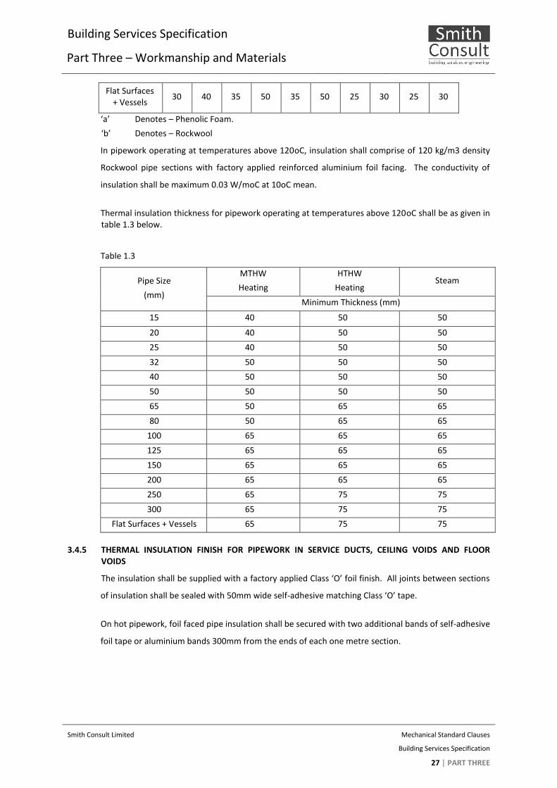
Flat Surfaces + Vessels
30 40 35 50 35 50 25 30 25 30
‘a’ Denotes – Phenolic Foam.
‘b’ Denotes – Rockwool
In pipework operating at temperatures above 120oC, insulation shall comprise of 120 kg/m3 density
Rockwool pipe sections with factory applied reinforced aluminium foil facing. The conductivity of
insulation shall be maximum 0.03 W/moC at 10oC mean.
Thermal insulation thickness for pipework operating at temperatures above 120oC shall be as given in table 1.3 below.
Table 1.3
Pipe Size
(mm)
MTHW
Heating
HTHW
Heating Steam
Minimum Thickness (mm)
15 40 50 50
20 40 50 50
25 40 50 50
32 50 50 50
40 50 50 50
50 50 50 50
65 50 65 65
80 50 65 65
100 65 65 65
125 65 65 65
150 65 65 65
200 65 65 65
250 65 75 75
300 65 75 75
Flat Surfaces + Vessels 65 75 75
3.4.5 THERMAL INSULATION FINISH FOR PIPEWORK IN SERVICE DUCTS, CEILING VOIDS AND FLOOR VOIDS
The insulation shall be supplied with a factory applied Class ‘O’ foil finish. All joints between sections
of insulation shall be sealed with 50mm wide self-adhesive matching Class ‘O’ tape.
On hot pipework, foil faced pipe insulation shall be secured with two additional bands of self-adhesive
foil tape or aluminium bands 300mm from the ends of each one metre section.
Building Services Specification
Part Three – Workmanship and Materials
Smith Consult Limited Mechanical Standard Clauses
Building Services Specification
28PART THREE
3.4.6 THERMAL INSULATION FINISH FOR PIPEWORK BEING INTERNAL AND EXPOSED TO VIEW (EXCLUDING PLANT ROOMS)
Insulation shall be wrapped with a 170g/m2 canvas membrane, fully adhered to the surface of the
insulation with adhesive. The canvas shall be stretched tight to eliminate any creases or wrinkles and
overlapped onto itself by at least 75mm along all joints. When the adhesion has fully dried, the outer
surface of the canvas shall be treated in accordance with the manufacturer’s instructions.
It is essential that the final finish is applied to a high standard. An additional two coat paint finish
shall be provided to an approved BS colour.
3.4.7 THERMAL INSULATION FINISH FOR PIPEWORK BEING INTERNAL IN PLANT ROOMS, BOILER HOUSES ETC.
The insulation finish shall be as for Service Ducts, Ceiling Voids and Floor Voids, but additionally
protected against possible mechanical damage by fabricated sheet aluminium casings.
All pipework insulation shall be enclosed in pre-rolled stucco embossed aluminium cladding secured
with aluminium bands at 450mm centres and at circumferential joints be overlapped by a minimum of
40mm.
The stucco enclosed aluminium cladding shall be 0.6mm thick on pipework up to 150mm diameter
and 0.8mm thick on all pipework above 150mm diameter. Elbows, bends, tees, sets etc. shall be
enclosed in stucco finished aluminium cladding to match the pipework using segmented pieces or
mitre bends where applicable.
The stucco embossed aluminium cladding shall be run through the bracket and support points.
3.4.8 THERMAL INSULATION FINISH FOR PIPEWORK BURIED IN TRENCHES AND COVERED WITH SELECTED BACKFILL (E.G. SAND OR FINE GRAVEL)
Where pipework is not of the pre-insulated type heavy density (80 kg/m3) pipe insulation shall be
used in place of standard density.
The insulation shall be finished with a protective covering of 100mm wide SERVI-WRAP T15A pipe
wrap tape spirally wrapped over the insulation with a 50% overlap or equal and approved finish.
3.4.9 THERMAL INSULATION FINISH FOR EXTERNAL PIPEWORK
All pipework external to the building and exposed to ambient conditions shall be insulated as
previously described and weatherproofed with 0.8mm reinforced polyisobutylene (P.I.B.) sheeting
adhered to the insulation with 50mm end and edge caps solvent welded and arranged to shed water.
Flanges, valves etc. shall be insulated with oversized segments of sectional insulation and
weatherproofed.
Building Services Specification
Part Three – Workmanship and Materials
Smith Consult Limited Mechanical Standard Clauses
Building Services Specification
29PART THREE
3.4.10 THERMAL INSULATION FINISH FOR PIPEWORK CONVEYING CHILLED OR COLD WATER
For pipework conveying chilled or cold water services, a continuous vapour seal shall be provided and
high density inserts shall be fitted between the pipe and the hanger brackets.
The inserts shall have the same thermal properties as the insulation material and be incompressible
and shall be approximately 100mm long. The outer diameter of the insert shall be identical to that of
the pipe insulation.
The insulation finish shall be continued over the inserts and the finish shall be protected by means of
sheet metal hoops under the brackets, against movement of the pipe and/or hanger.
Care must be taken to ensure the integrity of the vapour seal is maintained on all CWS and chilled
water pipework insulation. Where any edge requiring vapour sealing is exposed, continuity shall be
maintained by the application of a sealant.
3.4.11 INSULATION OF PIPELINE COMPONENTS
All flanges, valves and strainers etc. in plant rooms shall be fitted with removable boxes constructed
with 0.7mm thick aluminium sheeting lined with equivalent bonded insulation to the same thickness
as that on the accompanying pipework.
All such boxes shall be secured with “quick release” clips.
Flanges, valves etc. on chilled and cold water lines shall have vapour sealing maintained by the
application of a sealant.
3.4.12 INSTALLATION OF THERMAL INSULATION FOR DUCTED SERVICES
All thermal insulation shall be securely fixed to ductwork where practicable with a full bed application
of adhesives compatible with the insulation.
Insulation shall normally be adhered to the duct using general purpose two-way contact adhesive.
Inverted insulation shall be additionally secured with pre-bonded insulation pins and washers spaced
at 300mm centres. Insulation applied to ductwork, whose underside or standing side dimensions
exceed 600mm shall be mechanically attached to the duct surface with pre-bonded insulation pins
and washers, the spacing of which shall be a maximum of 300mm centres. On circular ductwork,
additional support to the insulation shall comprise circumferential bands of 100mm wide self-
adhesive foil tape applied at 300mm centres.
All rectangular ducting shall be insulated with slabs cut to fit on site so that the top and bottom slabs
overlap the sides at all four corners of the duct.

Building Services Specification
Part Three – Workmanship and Materials
Smith Consult Limited Mechanical Standard Clauses
Building Services Specification
30PART THREE
All circular ducting up to 350mm diameter shall be insulated with factory applied foil faced sections.
Above 350mm diameter, insulation shall comprise foil faced sections, back slotted, to allow it to be
fitted to the curvature of the duct.
All flat oval ducting shall be insulated with foil faced pre-formed half section on the semi-circular
sides, with the top and bottom to be insulated with foil faced flat sections.
Generally, all foil joints to the ductwork insulation and any protrusions throughout the facing shall be
sealed with 100mm wide self-adhesive aluminium foil tape.
Ductwork supports for insulated ductwork shall be in accordance with DW/144 incorporating a rigid
(tanalised softwood or similar) insulator between the support and the ductwork to the thickness of
the insulation with insulation vapour seal being taken through the insulator support and not over the
bracket.
3.4.13 THERMAL INSULATION MATERIALS FOR DUCTWORK
Insulation shall comprise of one of the following as specified:
a) 40 kg/m3 density CFC-free phenolic foam laminate with reinforced aluminium foil facing bonded to core during manufacture.
The conductivity of the laminate shall be maximum 0.018 W/moC at 10oC mean.
The laminate shall be Class ‘O’ rated to the Building Regulations – Approved Document B2/3/4 Appendix A Paragraph A12.
The insulation shall be Koolphen-K or Ductphen-K as manufactured by Kooltherm Insulation Products Ltd, or equal and approved.
b) 45 kg/m3 density rigid pre-formed Rockwool sections with factory applied aluminium foil facing
The conductivity of the insulation shall be a maximum of 0.03 W/moC at 10oC mean.
All insulation thickness applied shall be in accordance with table 1.4 below.
Table 1.4
Difference in Temperature Between Air Temperature
Within Duct and ambient Air
10oC 25
oC 50
oC
Minimum Thickness (mm.)
a b a b a b
25 30 30 40 40 50
‘a’ Denotes – Phenolic Foam
‘b’ Denotes – Rockwool
Building Services Specification
Part Three – Workmanship and Materials
Smith Consult Limited Mechanical Standard Clauses
Building Services Specification
31PART THREE
3.4.14 THERMAL INSULATION FINISH FOR DUCTWORK - SERVICE DUCTS, CEILING VOIDS AND FLOOR VOIDS
The insulation shall be supplied with a factory applied Class ‘O’ foil finish. All joints in the foil jacket
shall be sealed with 50mm wide self-adhesive matching Class ‘O’ tape.
All exposed edges of the insulation and where the jacket is penetrated by insulation pins or other
protrusions shall be sealed with a sealant or self-adhesive tape.
3.4.15 THERMAL INSULATION FINISH FOR DUCTWORK - INTERNAL, EXPOSED TO VIEW (EXCLUDING PLANT ROOMS)
Insulation shall be wrapped with a 170g/m2 canvas membrane, fully adhered to the surface of the
insulation with adhesive. The canvas shall be stretched tight to eliminate `any creases or wrinkles and
overlapped onto itself by at least 75mm along all joints. When the adhesion has fully dried the outer
surface of the canvas shall be treated in accordance with the manufacturer’s instructions.
It is essential that the final finish is applied to a high standard. An additional two coat paint finish
shall be applied to an approved BS colour.
3.4.16 DUCTWORK - INTERNAL IN PLANT ROOMS
The insulation finish shall be as for Service Ducts, Ceiling Voids and Floor Voids, but additionally
protected against possible mechanical damage by fabricated sheet aluminium casings of minimum
0.8mm thickness.
3.4.17 THERMAL INSULATION FINISH FOR EXTERNAL DUCTWORK
The ductwork shall be insulated as previously described and weatherproofed with 0.8mm
polyisobutylene (P.I.B.) sheeting adhered to the insulation with 50mm end and edge caps solvent
welded and arranged to shed water.
The P.I.B. sheeting shall be run through the bracket support points to provide a continuous
waterproof finish.
The top sides of rectangular ductwork insulation shall be fitted to falls to ensure shedding of water.
3.4.18 THERMAL INSULATION FINISH FOR DUCTWORK CONVEYING CONDITIONED, COOLED OR FRESH AIR
For ductwork conveying conditioned, cooled or fresh air, a continuous foil vapour seal shall be
provided and inserts shall be fitted between the ductwork and the hanger bracket.
The inserts shall have the same thermal properties as the insulation and shall be incompressible. The
insulation shall be taken up to the support inserts and sealed to the inserts. The vapour barrier shall
be carried through the supports enclosing the inserts.
Building Services Specification
Part Three – Workmanship and Materials
Smith Consult Limited Mechanical Standard Clauses
Building Services Specification
32PART THREE
Matching self-adhesive tape shall be applied to all insulation joints to prevent ingress of moisture or
capillary action. All penetrations for mechanical bonding to be sealed to maintain the vapour barrier.
The insulation shall cover the flanges by means of increasing the general thickness of insulation to
give at least 6mm cover at the flanges.
Any exposed edges of insulation or penetration of the vapour barrier shall be sealed with sealant or
self-adhesive tape.
The insulation shall be carefully formed around access openings, damper arms, test holes etc. to give
adequate access whilst maintaining the vapour seal.

Building Services Specification
Part Three – Workmanship and Materials
Smith Consult Limited Mechanical Standard Clauses
Building Services Specification
33PART THREE
3.5 HEATING
3.5.1 SCOPE
Heating systems shall comprise all necessary pipework, isolating and balancing valves, automatic
control, plant and equipment to form complete systems in accordance with the construction and
manufacturers’ drawings, Specification Parts 1,2 and 3 and Appendices and tender drawings.
Completed installations being defect-free, tested, balanced and commissioned together with the final
Operating, Maintenance & Instruction Manuals and Record Drawings, shall be handed over to the
Contract Administrator (CA) before the issue of the Practical Completion Certificate.
3.5.2 PRESSURE VESSELS
On completion of the installation the Contractor shall provide to the Employer’s insurance company
all information on the system expansion vessel as is required under Statutory Instrument No.2169
‘The Pressure Systems and Transportable Gas Containers Regulations 1989’.
The Contractor shall obtain from the insurance company a certificate for the installation and this shall
be included in the O & M Manual.
A written scheme for working on the vessel(s) shall also be included in the O & M Manual.
All equipment and their accessories together with the workmanship shall be carried out to the highest
quality and comply with all requirements detailed herein and publications as listed below.
The list of publications is indicative and not exhaustive. Where a published standard or guide is
appropriate to the specified product or method/quality of workmanship but not listed, it shall be
deemed to be included.
The work shall also be in accordance with all additional publications, revisions and amendments which
apply at the time of the installation.
3.5.3 BOILERS
General requirements
Boiler(s) must be installed strictly in accordance with the manufacturers’ instructions and shall be
commissioned and set to work by the manufacturer’s engineer or appointed agent. The
commissioning certificates shall be included in the O & M manual and laminated and fixed securely in
the respective boiler room.
All joints shall be rendered air-tight, to prevent air from entering and gases from leaking from the
combustion chamber, flue-ways and smoke connections.

Building Services Specification
Part Three – Workmanship and Materials
Smith Consult Limited Mechanical Standard Clauses
Building Services Specification
34PART THREE
Doors and plates covering orifices into the combustion chamber are to close tightly, and shall be free
from warping.
Where sectional boilers are constructed on site they shall be flushed out with clean water after
assembly before pipe connections are made.
All floor standing boilers shall be mounted on builder’s work bases.
Boilers shall be suitable for the fuel and firing method detailed elsewhere.
Cast iron boilers are to comply with BS 799 where applicable.
Welded steel boilers are to comply with BS 855 where applicable.
Boilers shall be provided with maker’s standard casings, insulation, controls and instrumentation, and
shall be suitable for the working pressure of the system.
Where gas fired boilers are installed, whether fitted with forced draught or natural draught burners, a
gas leak detector system is to be fitted in the boiler house, as detailed elsewhere.
All condensing boilers shall include a condense connection. Condense shall be carried away from the
boiler to the buildings drainage system via suitable plastic pipe. Under no circumstances shall copper
or steel pipe be used.
Controls
The boiler(s) shall be manufactured with an integral, adjustable water temperature control
thermostat suitably ranged for the operating temperature of the system to be served. The adjustment
may be effected by manual or automatic means as detailed elsewhere.
The boiler(s) shall be manufactured with an integral water temperature over heat high limit cut out
thermostat with manual resetting.
Gas fired boilers shall be supplied with an integral gas control valve incorporating all safety devices.
All boilers shall be fitted with a thermometer, an altitude or pressure gauge, a safety valve and drain
cocks, in accordance with the following details.
Where not an integral part of the boiler, thermometers and altitude/pressure gauges shall be of a
similar make and style.
Thermometers are either to be integral part of the boiler instrumentation provided as standard by the
boiler manufacturer, or one of the following types, as given in the Particular Specification:

Building Services Specification
Part Three – Workmanship and Materials
Smith Consult Limited Mechanical Standard Clauses
Building Services Specification
35PART THREE
a) To BS EN 1319 : mercury in steel type, dial thermometers of 1mm diameter, vertical or
coaxial. They shall have black steel cases with chromium plated bezels, and the dials and
indicating hands shall be protected by a plain glass front. The dials shall be calibrated from °C
to 12°C.
b) Where indicated in the Particular Specification small dial thermometers of 65mm diameter
approximately shall be fitted to the boiler. They shall be of the bimetal co-axial type,
calibrated from 1°C to 12°C, having either a red and white moving indicator disc or a black
pointer, and a fixed temperature scale, with a plain glass front. Dial type thermometers shall
be provided with tails screwed 15mm BSP male. A separate steel well, threaded 25mm BSP
male by 15mm BSP female is to be fitted into the pocket and filled with heat-conducting
grease before the insertion of the thermometer.
Where thermometers are installed in pipelines and the diameter of the pipe is too small for the length
of the standard bulb, the pipe shall be increased to the requisite diameter for the length of 15mm to
allow for the proper fitting and insertion of the thermometer well.
Thermometers should be fitted on the flow mains close to the boilers and in positions where they can
be read easily.
Altitude and pressure gauges to BS 178 with 1mm diameter dial, having a brass case, with 1mm BSP
bottom connection. Gauges shall be calibrated in metres head and bars pressure, the maximum scale
range being no more than one and a half times the working pressure of the system.
Gauges of excessive scale range will be rejected. The indicating hand is to be black and an additional
red hand is to be fitted which shall be set to the standing head of the system. A plain glass front is to
be fitted to the gauge to protect the dial and indicators.
A lever handle isolating cock is to be fitted between the gauge and the boiler/pipe.
Gauges are normally to be fitted to a tapping at the front of the boilers, but where manufacturers do
not provide for this, gauges shall be fitted on the flow main close to the boilers and in positions where
they can be read easily.
Connections
Boiler connections shall include flow, return, open vent (as necessary), cold feed, drain off and safety
valve of the size and type shown in the boiler schedule and indicated on the drawings.

Building Services Specification
Part Three – Workmanship and Materials
Smith Consult Limited Mechanical Standard Clauses
Building Services Specification
36PART THREE
Spring loaded safety valves of appropriate size for the boiler rating and correctly loaded for the
maximum working pressure shall be fitted. All safety valves shall have a copper or galvanised steel
overflow pipe carried clear of the boiler insulation and turned over to discharge downwards.
Safety valves shall be padlocked and keys shall be handed over to the person responsible for building
or the Main contractor whichever is appropriate to the type of contract.
Emptying cocks shall be fitted to each boiler, to enable all the water to be drained.
Where it is not possible to fit the mountings directly on to the boiler, they may be fitted to the flow or
return pipework connections, as appropriate, as close to the boiler as possible, before any valves.
Where two or more boilers are connected together on open vented systems, a safety vent pipe
connection of the size shown on the drawing shall be run from each boiler and connected to a
common boiler safety vent pipe, via a three-way safety vent cock, arranged so that the boiler vent
connection is always open to atmosphere.
A relief pipe is to be run from the third connection of the vent cock, carried clear of the boiler and
turned down to discharge to within 45mm of floor.
Locating
Floor mounted boilers shall be situated on a solid plinth of dimensions as indicated on the drawings.
This plinth shall be of a strong, smooth non-combustible construction with a level finish.
Wall mounted boilers shall be supplied with all brackets and fixtures as detailed in the manufacturers’
instructions.
Maintenance
The boilers shall be located to give all round clearances for maintenance and dismantling strictly in
accordance with the drawings and manufacturers minimum requirements and instructions.
Cleaning tools
Cleaning tools and brushes shall be supplied with each boiler mounted on a board in the boiler room.
Documentation and certification
All boilers shall be supplied with a full set of the following documentation:
i. Installation instructions.
ii. Maintenance instructions which are to include a spare parts schedule.

Building Services Specification
Part Three – Workmanship and Materials
Smith Consult Limited Mechanical Standard Clauses
Building Services Specification
37PART THREE
iii. User instructions.
Boilers shall be provided with test certificates, model numbers and data badges.
Sectional boilers fabricated on site by the manufacturer shall be pressure tested to twice the system
working pressure and then heat tested during commissioning. After satisfactory testing, a certificate
must be issued by the manufacturer. This certificate will be included with the O & M manual.
3.5.4 BURNERS
General requirements
Burners shall be provided as either an integral part of the boiler assembly or as a manufacturer’s
matched component to the details as given in the Particular Specification and Equipment Schedules.
Pressure jet oil burners
Oil burners shall be of the fully automatic pressure jet pattern, incorporating fuel pump, fan, start and
purge timing device, EHT electrical ignition and photo electric flame failure shut off device.
Oil burners shall be manufactured and installed in accordance with the current edition of BS 799:Part
3, current edition.
Oil burners shall be fitted with a flexible oil connection run from the oil feed line and the feed line is
to terminate with a gate valve and oil filter. The filter is to be suitable for the grade of oil in use and
shall have a transparent bowl of unbreakable material.
Where the oil feed system is of the independently pumped circulatory type, an oil pressure reducing
valve is to be fitted immediately after the isolating valve. The reducing valve is to be set to give an
outlet oil pressure consistent with the requirements of the oil burners.
The Contractor shall include for a return visit to site after the plant has been in operation for one
month to undertake final test readings and adjustment of burners, including any change of nozzles. A
written report shall be forwarded to the Contract Administrator (CA), quoting for each boiler:
1. Flue gas outlet temperature.
2. CO2 reading.
3. Smoke number.
4. Combustion efficiency.

Building Services Specification
Part Three – Workmanship and Materials
Smith Consult Limited Mechanical Standard Clauses
Building Services Specification
38PART THREE
Forced draught gas burners
Gas burners shall be of the fully automatic forced draught type, incorporating fan, start and purge
timing device, EHT electrical ignition and photo-electric flame failure shut off device (for the
remainder of gas equipment refer to the relevant section).
Gas burner installations are to comply with current legislation and IGEM publications.
3.5.5 SEALED HEATING SYSTEMS
Pumped pressurisation unit
The filling pump set shall comprise a break tank including a ball valve and overflow pipe, a pump to fill
the heating system from the break tank and air cushion, a pressure reducing valve to be set to 1%
above the cold fill pressure of the system, a system expansion vessel and a contactor/starter, all being
mounted on a suitable baseplate or brackets.
The filling pump set is to be controlled by a pressure sensing switch set to the cold fill pressure of the
system. This switch is to be mounted on the filling pump set or in the cold feed pipe from the set to
the boiler but no valve shall be installed between the pressure reducing valve of the filling set and the
pressure sensing switch.
A non-return valve is to be fitted in the pump suction pipe from the break tank and a 5mm diameter
pressure gauge is to be fitted in the outlet pipe from the reducing valve. Provide and install in the
main flow pipe close to the boiler, two pressure sensing switches for high and low pressure limiting
purposes.
These high and low limit pressure sensing switches shall be wired to shut down the boilers if pressures
rise or fall beyond the limits stated in the Schedule.
The standing head of the system, the cold fill pressure and the maximum working pressure shall be as
stated in the Schedule.
The pump motor is to be a wound for a 24v/1ph/5Hz electrical supply and the filling pump set is to be
internally pre-wired.
On completion of the installation the Contractor shall provide to the Employer’s insurance company
all information on the system expansion vessel as is required under Statutory Instrument No.2169
“The Pressure Systems and Transportable Gas Containers Regulations 1989”.
The Contractor shall obtain from the insurance company a certificate for the installation and this shall
be included in the O & M Manual.

Building Services Specification
Part Three – Workmanship and Materials
Smith Consult Limited Mechanical Standard Clauses
Building Services Specification
39PART THREE
A written scheme for working on the vessel(s) shall also be provided in the O & M Manual.
Pump-free pressurisation unit
A proprietary WRAS approved pump-free fill set shall be used as detailed elsewhere.
The unit shall be complete with high and low pressure controls suitable for relaying to the BMS and/or
local control panel.
Other control requirements shall be as given in the Automatic Controls Section B10.
Expansion vessels for sealed systems
Where boilers are installed in sealed and pressurised systems, no open vents are required.
An air separator, incorporating automatic air vent, of the size, type and make given in the Particular
Specification, is to be fitted in the main flow connection from each boiler of sealed pressurised
systems.
Closed expansion vessels to BS 4814 of the size, type and make given in the Particular Specification
shall be connected to all sealed or pressurised systems.
3.5.6 METERING
The cold feed to the heating system shall be fitted with a secondary water meter.
The meter shall be pulse type and linked to the Auto/BMS controls for remote monitoring.
3.5.7 CIRCULATING PUMPS
Provide and install in the positions shown on the drawings, accelerator pumps for heating and HWS
primary circulations. They shall be of the number, duty, make and type given in the Schedule
Pumps shall be arranged to operate in duty and standby mode.
Each pump shall be capable of performing the duty given in the Schedule and shall be fitted with a
nameplate giving the following details:
1. Maker’s name.
2. Volume flow rate (litre/s).
3. Developed pressure (millibars).
4. Pump speed (rev/s).

Building Services Specification
Part Three – Workmanship and Materials
Smith Consult Limited Mechanical Standard Clauses
Building Services Specification
40PART THREE
5. Maker’s reference.
Each pump motor shall be fitted with a nameplate giving the following minimum particulars:
1. Maker’s name.
2. Model reference number.
3. Details of electric supply.
4. Motor speed (rev/s).
Centrifugal type pumps shall be belt driven or directly coupled to the driving motors. Directly coupled
pumps shall be mounted on a common bed plate. A sensitive non-return valve shall be fitted in the
main between the pump suction and delivery branches and isolation valves shall be fitted to latter.
All pumps with indirect drive shall be fitted with galvanised sheet steel or wire mesh guard over the
pump drive.
Motors shall be resiliently mounted on all indirect drive pumps to ensure freedom from vibration in
the pipework and quiet operation.
Lubricated bearings on pumps or motors shall be of sleeve or bush pattern with adequate oil
reservoirs.
All electric motors shall be of the totally enclosed type, wound for the electric supply available,
maximum speed 24 rev/s manufactured strictly in accordance with the appropriate BS Specification
for continuous operation in the ambient temperature conditions prevailing. They must be fully
capable of driving the pump at the required duty with reasonable margin against overload.
All floor mounted pumps shall be properly levelled on suitable foundation, bolts being provided for
grouting in by builder, to details supplied by Contractor if the type of pump used has a bed plate.
In line pumps intended for connecting directly into the pipework shall not cause undue deflection of
the pipe and the supports of the latter must be arranged with due regard to the weight of pump unit.
Pumps of this type shall either have combined packless glands and seals or be of the immersed rotor
type.
Pumps which embody an automatic non-return valve in by-pass shall have isolation valves on the
suction and delivery branches arranged so that the pump itself can be isolated and removed without
the necessity of emptying the system. Pumps of this type which have repackable glands shall be so
Building Services Specification
Part Three – Workmanship and Materials
Smith Consult Limited Mechanical Standard Clauses
Building Services Specification
41PART THREE
designed that the water pressure can be shut off from the stuffing box to permit repacking when
required without necessitating emptying of the system.
The Contractor shall supply and fix within the boiler room adjacent to the pumps, blanking plates
suitable to allow the out of use pump head of twin headed pump sets to be removed for
maintenance. One blanking plate per pump set shall be provided whether or not there are duplicates.
Tappings shall be provided at the inlet and outlet connections of pumps in heating systems outside
the pump isolating valves.
Connections shall be run from these to two matched altitude gauges. The gauges shall be as
previously described and shall be fitted with lever operated gauge cocks.
Heating and HWS primary pumps are to have cast iron bodies.
Isolator/changeover switches and starters shall be suitable both for the available electrical supply and
for the motors to which they shall be connected.
Starters for pump motors must not incorporate a no-volt release device, as pumps are required to run
immediately the supply is resumed after an electrical shut off.
Starters for three phase motors are to incorporate a single phase prevention cut out.
The electrical control gear for the pumps is to be incorporated in a control panel.
Pumps shall be installed in accordance with the manufacturer’s recommendations. Any ambiguity
shall be brought to the CA’s attention.
3.5.8 RADIATORS AND SUPPORTS
General requirements
All low surface temperature radiators shall comply with NHS Estates Health Guidance Note (March
1998). This shall be understood to impose a maximum surface temperature of 43C at any point on
the case or grilles. Particular attention should be given to installing LST radiators strictly in accordance
with the manufacturer’s recommendations. Any deviation can be detrimental to the output and
surface temperature.
The Contractor shall check dimensions of all radiators before ordering to ensure they can be
accommodated in spaces available.

Building Services Specification
Part Three – Workmanship and Materials
Smith Consult Limited Mechanical Standard Clauses
Building Services Specification
42PART THREE
All radiators shall be provided with air cocks and three air cock keys shall be given to the Client on
Handover.
Radiators shall not have their tops protruding above the level of window sills.
Cast iron radiators shall be free from hair cracking, scale and foundry sand.
Steel radiators shall be free from dents, bending, twisting and pinholes.
All radiators shall be constructed and tested in accordance with BSEN442, including a works pressure
test to 1 bar and shall be in a primer or powder coat finish as detailed elsewhere.
All visible supports, feet, brackets etc. must be of the same finish as the radiator.
Connections at an angle which throw the valves out of vertical alignment shall not be accepted.
The Contractor shall include for taking all radiators down twice after erection for painting purposes
and for re-fixing and leaving in sound working order.
All radiators shall be without feet unless stated otherwise in the Particular Specification or in the
Equipment Schedule.
All radiator supports must be neatly and cleanly made and fixed in true vertical and horizontal
alignment. When necessitated by the building construction, all or most of the weight shall be carried
by the floor on the manufacturer’s radiator feet.
The number of bottom brackets provided shall be adequate for the length and weight of radiator as
recommended by the radiator manufacturer.
Cast iron radiators shall be provided with a mild steel top stay, either built into wall or secured
thereto by screws in the case of woodwork.
Steel radiators shall be supported from maker’s standard concealed brackets.
In all cases where required to accommodate the expansion of movement of pipework, supports and
stays must be of the type which shall allow completely free lateral movement. Failure to meet this
requirement which may be disclosed after the application of heat to the system shall be rectified at
the expense of the Contractor including the cost of any additional builder’s work or other attendance
involved.

Building Services Specification
Part Three – Workmanship and Materials
Smith Consult Limited Mechanical Standard Clauses
Building Services Specification
43PART THREE
Contractors shall ensure that all supports of any kind for radiators are adequately and securely fixed.
Responsibility for all rectification involved in bad fixing of radiator supports shall rest solely with the
Contractor.
Radiator valves
Dezincification resistant copper alloy to BS 2767, screwed B.S. 21 taper, complete with union nut and
tailpiece. Handwheel and lockshield head in white or ivory-coloured, tough stain free plastic.
Finishes shall be polished chrome unless.
Radiator valves shall be manufactured from cast gunmetal or bronze and comply with BS 2767, of
straight or angle pattern as appropriate, with brass construction.
Where copper or stainless steel pipework is used for the heating system, the connection of radiator
valves shall have compression joints to BS 864 Part 2. Elsewhere radiator valve feed connections shall
be female pipe threads to BS 21.
Thermostatic radiator valves (TRV)
Valves shall be suitable for the system temperature range with replacement head, stem, seal and
valve seat, without shutting down the system, and capable of positive shut-off for isolation.
Where thermostatic radiator valves are designed to be positioned in flow connections to the radiator
fit a matching finish lockshield valve in the return connections. Before the thermostatic radiator valve
fit a ball valve and concealed Allen key operated drain cock on the dead side of the isolating valve for
radiator isolation and draining.
Where main flow pipe is exposed under radiator, fit a thermostatic valve on the radiator top entry.
Provide thermostatic radiator valves to BS 6284, and B.S. 21 with tape threads on both ports and
complete with union nut and tailpiece.

Building Services Specification
Part Three – Workmanship and Materials
Smith Consult Limited Mechanical Standard Clauses
Building Services Specification
44PART THREE
3.6 ABOVE GROUND SANITARY PLUMBING AND DRAINAGE INSTALLATION
3.6.1 GENERAL
The installation shall be of the highest order and in accordance with the latest edition of all relevant
British Standards (including Codes of Practice) and the prevailing Statutory and Local Authority
Regulations applicable to these works (i.e. Public Health Act and Building Regulations Part H etc.),
Local Authority and Water Bye-Laws.
All pipework and components shall comply with British Standards requirements and shall have the BS
Kite-mark.
3.6.2 PIPEWORK FALLS
All waste pipework, including ventilating pipes, shall be laid to gradient fall to comply with BS 5572.
Horizontal rainwater pipework shall be laid to fall at approximately 1:48 (22mm/m run).
3.6.3 CAST IRON PIPEWORK AND FITTINGS
Cast iron pipes and fittings shall comply with BS 416, with couplings to BS 6087 or ISO 6594 with
couplings to ISO 4633/6447/6448.
The jointing of pipes shall be by means of cast iron bolted coupling assemblies with elastomer seals
and stainless steel nuts and bolts. Earth continuity strips or couplings shall be provided throughout.
Jointing shall be carried out in accordance with the manufacturer’s recommendations, with bolts
being tightened to the specified torque, using an approved torque wrench.
3.6.4 COPPER PIPEWORK AND FITTINGS
Copper pipework shall comply with BS EN1057. Copper fittings shall comply with BS EN1254
The jointing of copper pipes up to and including 54mm. diameter shall be by means of capillary
soldered joints or compression type fittings.
Copper pipework greater than 54mm. in diameter may be jointed with bronze weldable fittings, to BS
1724.
Copper pipework and fittings where exposed to view shall be high quality chromium plated finish
together with support fittings.
3.6.5 PVC-U AND MUPVC PIPEWORK AND FITTINGS
PVC-U pipework and fittings shall comply with BS 4514 and MUPVC pipework and fittings shall comply
with BS 5255. Pipework and fittings for rainwater services shall additionally comply with BS 4576.

Building Services Specification
Part Three – Workmanship and Materials
Smith Consult Limited Mechanical Standard Clauses
Building Services Specification
45PART THREE
Joints shall be spigot and socket with solvent cement with provision for expansion using push fit
sockets and connectors with rubber joint rings installed to manufacturer’s recommendations.
Where PVC-U pipes pass through fire compartment walls or floors, an intumescent “fire sleeve” shall
be provided, installed in accordance with the manufacturer’s recommendations.
3.6.6 WORKMANSHIP
Prevent the entry of foreign matter into any part of the system during construction.
Cutting of pipe ends shall be clean and square and using equipment appropriate to the material.
Bending of pipes shall be carried out on approved bending machines, or by methods approved by the
pipe manufacturer.
All pipes passing through roofs and external walls shall be weathered with a roof connector suitable
for the roof or wall finish.
Ventilation pipes shall rise full bore to 460mm above eaves or roof level, and in any case not less than
900mm. above the head of, or within, a horizontal distance of 3.00m from any window. The outlet of
any discharge stack shall be protected at its top-most end with a domical cage or other cover which
does not restrict air flow.
Access shall be provided on main soil pipes above every floor and at principle junctions and changes
of direction to enable pipework to be cleared in the event of a blockage.
Access shall be provided on vertical rainwater pipes 600mm. above finished ground or floor level.
Connections to underground drainage shall be via a purpose made fitting or coupling to ensure a
watertight joint.
All installed red oxide, epoxy or bituminous coated cast iron pipework shall be left in clean condition,
and shall be wire brushed and painted with a final coat of protective paint prior to handover.
All cast iron pipes shall be securely fixed to walls on build in pattern holderbats or duct brackets at
centres not greater than 2.00m.
Suspended cast iron pipework shall be supported by purpose made hangers, with one hanger 300mm.
max. from each joint and a second positioned approximately centrally in a 3m. pipe length
(approximately 1.5m. centres). All in accordance with the manufacturer’s recommendations.

Building Services Specification
Part Three – Workmanship and Materials
Smith Consult Limited Mechanical Standard Clauses
Building Services Specification
46PART THREE
All iron work, brackets, drop rods etc. not otherwise protected, shall be painted with two coats of red-
oxide or bituminous paint, with 48 hours between applications.
Copper pipes shall be capillary soldered using a suitable flux, and care should be taken to remove all
traces of flux on completion of the joint.
All copper pipework shall be installed to true lines and falls and shall be fixed clear of walls with
approved brackets plugged and screwed to the structure at centres not greater than 2.0m. using brass
screws.
Copper pipework shall be supported by two piece copper alloy Munsen ring with short studding
length and screw to wall backplate.
Galvanised Unistrut support with drop rod and two piece ring clip shall be used for suspended
pipework.
All floor gully traps shall be supported independently from pipework.
PVC-U and MUPVC pipework shall be supported by means of manufacturer’s standard support
bracket assembly secured to structure.
The Sub-Contractor shall ensure provisions are made in PVC-U and MUPVC installations, for expansion
and contraction due to changes in temperature, in full compliance with the manufacturer’s
recommendations.
Supports and holderbats for PVC-U pipework shall be of galvanised steel two piece construction to
allow for thermal movement, secured to the structure using 40mm. stainless steel screws and plugs.
Supports shall be provided on horizontal pipework at 1m intervals (maximum). Thermal movement
limits shall be employed on horizontal pipework at 4m intervals (maximum). Pipe supports on vertical
pipework shall be at 2m intervals (maximum), with thermal expansion joints at 4m intervals
(maximum).
Supports for MUPVC waste pipes up to and including 50mm diameter shall be MUPVC or zinc plated
steel of the same manufacturer as the pipework, secured to the structure at 500mm (maximum)
intervals using 40mm stainless steel screws and plugs.
3.6.7 TRAPS TO SANITARY FITTINGS AND WC CONNECTIONS
All traps to waste fittings shall have a minimum 75mm seal and shall be easily accessible, removable,
and provided with adequate means of cleaning.
Traps shall be copper tubular two piece ‘P’ or ‘S’ running traps with compression fittings.

Building Services Specification
Part Three – Workmanship and Materials
Smith Consult Limited Mechanical Standard Clauses
Building Services Specification
47PART THREE
Traps in visible locations shall be chromium plated copper bottle type traps.
WC connections shall be by means of purpose made self-sealing connectors, compatible with the soil
pipework system.
3.6.8 STORAGE AND CHECKING OF PIPES AND FITTINGS
Pipes and fittings whilst stored on site shall be stacked in such a manner to avoid overloading the
bottom layers and shall not rest directly in the ground. Sockets shall not rest on other pipes and the
manufacturer’s recommendations shall be followed regarding height of pipe stacks. Plastic pipework
shall be protected from direct sunlight.
All pipes and fittings shall be examined and particular attention is to be paid to factory applied
jointing material, specifically contoured spigots and sockets, and works applied protective coatings.
Any pipe which is found to be damaged in any way whatsoever shall be rejected and replaced.
Pipes and fittings shall also be examined for any deformities or roughness in the pipe bore. All access
covers shall be removed to ensure a clear and free entry to the pipe. All junctions shall be examined
to ensure all fetting has been removed.
3.6.9 INSTALLATION OF SANITARY APPLIANCES
3.6.10 GENERAL
Where specified the Sub-Contractor shall include for the installation of sanitary appliances supplied
by others.
The Sub-Contractor shall be responsible for accurately setting out all appliances in accordance with
the detailed contract drawings and shall draw attention to any cast-in underslab drainage that
conflicts with such setting out requirements.
All appliances shall be drawn from The Contractor’s store, taken to the fixing position and installed to
manufacturer’s and Architect’s specific installation instructions and detail.
The Contractor shall provide protection to appliances after installation against damage, breakage or
vandalism.
Appliances shall be complete with all fixtures and fittings including taps, valves and traps etc. as
scheduled.
No order shall be placed for sanitary appliances until confirmation of final appliance selection has
been obtained from the Architect and Engineer.

Building Services Specification
Part Three – Workmanship and Materials
Smith Consult Limited Mechanical Standard Clauses
Building Services Specification
48PART THREE
All sanitary appliances shall be fixed rigid, level, and fully in accordance with the manufacturer’s
recommendations.
Waste outlets shall be fixed by means of mastic and plastic washer joints and shall be thoroughly
watertight, with all surplus mastic and the like removed.
Care shall be taken to ensure that no damage or strain of any type is caused to any fitment by over
tightening waste outlets, taps, brackets or fixings etc.
Urinal flushpipes shall be adequately and securely fixed to the wall, with additional pipe clips being
employed if necessary, or requested by the Engineer.
All ceramic sanitary fittings shall be pointed at all exposed edges/wall surfaces with colour co-
ordinated silicone sealant, smoothed to give a neat, watertight joint.
Stainless steel sink units shall be bedded and fitted to worktops in a level, rigid and watertight
manner. All sinks shall be installed to drain fully.
3.6.11 FINAL CONNECTIONS
The final water service connections to all sanitary appliances shall be undertaken in rigid pipework,
flexible connections will not be permitted.
3.6.12 WC OVERFLOW INSTALLATION
WC overflows shall, where indicated on the drawings, discharge through the external wall and shall
protrude 100mm from the wall face, and terminate square cut, with all edges filed smooth.
Overflows from WC cisterns within deep plan internal areas shall discharge through the plumbing
panel via chromium plated fittings, as Armitage Shanks reference 0164047CP.IPS 160mm above the
centre of the WC pans.
Overflows from WC cisterns shall discharge via “Indiflow” visible tundish type units as Armitage
Shanks reference 7643A9Z PO IPS.
Overflows shall be installed in copper pipework to BS EN1057 with fittings to BS EN1254.
Pipework shall be supported using screw to wall pipe clips with stainless steel screws and plugs.
3.6.13 TESTING
On completion and prior to handover, all pipework shall be checked and left free from obstruction
and shall receive a final air test in accordance with BS 5572, or as directed by the local Building
Control Officer, which shall be witnessed by the Building Control Officer and the Engineer.

Building Services Specification
Part Three – Workmanship and Materials
Smith Consult Limited Mechanical Standard Clauses
Building Services Specification
49PART THREE
Upon satisfactory completion of the testing, a signed certificate of soundness shall be issued,
countersigned by the Local Authority’s Inspector. Any defects which occur during testing shall be
rectified and re-tested to the Local Authority’s satisfaction.
3.6.14 COMMISSIONING
3.6.15 SANITARY APPLIANCES
All sanitary appliances shall be checked for damage, component completeness, satisfactory operation,
stability and alignment. All terms found incomplete or damaged shall be replaced.
Thoroughly clean all appliances to remove all stains and manufacturer’s labels/wrapping etc. ease all
taps and vales applying approved lubricant and re-pack stuffing glands where necessary.
Ensure taps are securely fixed to sanitary ware and properly aligned.
Check efficiency of flush to all urinal and WC bowls.
Test WC pans by flushing and test other appliances by filling to overflow level and emptying.
Test each appliance individually for self-siphonage, then for induced siphonage and back pressure by
multiple/range testing.

Building Services Specification
Part Three – Workmanship and Materials
Smith Consult Limited Mechanical Standard Clauses
Building Services Specification
50PART THREE
3.7 REFRIGERATION PIPEWORK SERVICES
3.7.1 GENERAL
The entire installation shall comply with BS 4434.
3.7.2 INSTALLATION
Pipework shall be designed and run so that any oil in the compressor discharge refrigerant which
passes through the oil separator (where fitted) is carried through the system and returned.
At any point where a large quantity of oil may accumulate, an oil separator and a means of returning
oil to the compressor shall be provided.
Pipework shall be installed dead flat.
All tube for refrigeration purposes shall be capped at all times other than when actually being
installed. It is imperative that the inside of the tube is kept free from dirt and moisture at all times.
3.7.3 JOINTING
All joints made on a refrigeration system are to be brazed, screwed or flanged.
Flanged joints will only be accepted on components inserted within the system such as sight glass,
drier, solenoid valve and only when 5/8” or below, or on proprietary items supplied such as
compressor condenser etc.
Flanged joints will only be accepted on proprietary items and components such as sight glasses,
driers, solenoid valves etc. and where the connection sizes are 5/8” or greater.
Screwed joints will be accepted only on plant items and only for control or test purposes. These
joints are not to be used on connections greater than 1/2” and to be sealed using PTFE tape.
All other joints will be brazed.
Flared connectors, soft soldering etc. will not be acceptable.
When brazing is being carried out oxygen free nitrogen should be passed through the pipework to
displace the oxygen within the pipework to ensure that no oxidisation takes place.
Brazing should be carried out by a skilled operative in accordance with the HVCA Code of Practice.

Building Services Specification
Part Three – Workmanship and Materials
Smith Consult Limited Mechanical Standard Clauses
Building Services Specification
51PART THREE
No copper tube for refrigeration purposes shall be cut using a hacksaw or any tool which creates
fillings which will contaminate the system. Any operative found using any such tool will be removed
from site immediately and all of his previous work removed and replaced at no cost to the Employer.
3.7.4 PIPEWORK SUPPORTS
All pipework shall be supported along its entire length via medium grade galvanised Admiralty pattern
cable tray. The pipework shall be clipped at the following minimum intervals:-
Pipe Size 1/2” 5/8” 3/4” 7/8” 1/8” 1 3/8” 1 5/8” 2 1/8” 2 5/8”
Horizontal 1.2m. 1.2m. 1.5m. 1.5m. 1.5m. 1.8m. 1.8m. 2m. 1m.
Vertical 1.5m. 1.5m. 1.8m. 1.8m. 1.8m. 2.4m. 2.4m. 2.4m. 2.4m.
3.7.5 PIPEWORK SIZING AND DESIGN
The Sub-Contractor shall size and design the pipework system in accordance with the requirements
dictated by the equipment manufacturer.
3.7.6 VALVES AND ACCESSORIES
Valves required for compressor, liquid receivers etc. shall be of either diaphragm or bellows type or
be packed valves complete with a back seating and seal cap.
Oil separators shall be fitted on systems with extremely long pipe runs to provide early return of oil.
Hot gas mufflers shall be fitted on systems over 70 kW to prevent pulsation noise.
Non return valves shall be fitted where danger of migration occurs.
Sight glasses shall be fitted to systems with R.E. greater than 15 kW.
Driers shall be fitted where the equipment manufacturer so recommends and generally on plant over
15 kW R.E and shall be 2 way on heat pump systems.
3.7.7 THERMAL INSULATION
Refrigeration pipework shall be insulated with a material having a thermal conductivity of less than
0.4 W/moC and at least 12mm. thick for pipes of up to 80mm. diameter and 19mm. thick for pipes
100mm. and above. This insulation shall be protected by a vapour barrier which shall not be broken
between joints of sectional material or at discontinuities at valves or brackets.
3.7.8 REFRIGERANT RECOVERY
Under no circumstances shall refrigerant be allowed to escape to atmosphere.
All systems shall be provided with connection points to facilitate the simple connection of refrigerant
recovery plant.

Building Services Specification
Part Three – Workmanship and Materials
Smith Consult Limited Mechanical Standard Clauses
Building Services Specification
52PART THREE
3.7.9 TESTING AND EVACUATION
The entire refrigeration system shall be pressure tested at 100 psi. If the high and low side of the
system are able to be separately tested the high side shall be tested to 350 psi ensuring that no
damage can occur to low pressure components.
Leak checking shall be carried out by halide torch or similar if the system fails to hold its pressure over
24 hours.
Once the system has passed the pressure test, the test mix should be released and vacuum pump
placed on the system. All parts of the system in the low and high side should be open to the vacuum
pump. To achieve this, it may be necessary to evacuate more than one point on the system.
3.7.10 SYSTEMS UNDER 40 KW
Once the system has achieved a vacuum of 1 torr the system should be left on the vacuum pump for
minimum of four hours to twenty four if possible. After this time the gauges should be closed and the
vacuum pump disconnected. The system should hold 1 torr for an hour. After this time the system
may be charged taking care not to allow air into the system.
3.7.11 SYSTEMS OVER 40 KW
After the first evacuation achieves 1 torr, the system should be closed and the vacuum pump
disconnected. The system should hold 1 torr for 1 hour after which time it should be filled with
oxygen free nitrogen to a pressure of 30 psi. The nitrogen should then be released until it reaches a
pressure of below 3 psi and the vacuum pump reconnected. This process should be repeated 4 times,
after which time the system will be ready to charge.
3.7.12 REFRIGERATION SYSTEM COMMISSIONING
Commissioning shall be carried out in accordance with CIBSE Code R.

Building Services Specification
Part Three – Workmanship and Materials
Smith Consult Limited Mechanical Standard Clauses
Building Services Specification
53PART THREE
3.8 PAINTING, POLISHING, CLEANING AND CONTRACT IDENTIFICATION
3.8.1 PLANT AND EQUIPMENT
All bright, polished, machined parts, factory painted panels, chrome plates or similar finished
components shall be wrapped with self-adhesive plastic, this shall be maintained until the component
is put into use. Allow for removing the wrapping, clean up and reinstate the finish to the
manufacturer’s finish immediately prior to handover.
3.8.2 PROTECTIVE PAINTING AND COVERINGS
All pipework, fittings, supports and other such ferrous material shall be primed in situ. Associated
brackets and supports may be primed before despatch to site but in any case must be primed before
fixing to any structure. Materials to be primed shall first be thoroughly cleaned from scale, rust, dirt
and grease etc. before applying one coat of heavy duty brushing quality zinc phosphate primer to an
average dry coat thickness of 0.05mm.
In the case of galvanised pipework and fittings an etch primer shall be applied prior to the zinc
phosphate primer.
Any damage received to a primed surface shall be made good by cleaning down to bare metal by wire
brushing and painted with two coats of red oxide primer to BS 2524. The whole material shall then be
painted with one further coat of red oxide then one coat of heat resistant black gloss paint to BS
4800.
Where uninsulated or otherwise exposed, a two coat gloss colour paint finish shall be applied to all
pipework services as follows:-
a. Gas Services - Yellow Ochre to BS 6800
b. Fire Fighting Services - Post Office Red
c. Other - As agreed with the Engineer
3.8.3 CLEANING
Immediately prior to handover, ensure that all plant and plant rooms are in a clean and acceptable
condition.
All exposed valves, fittings etc. shall be thoroughly cleaned and polished on completion of all painting
and prior to handover.
3.8.4 SERVICE IDENTIFICATION AND LABELLING
Valves

Building Services Specification
Part Three – Workmanship and Materials
Smith Consult Limited Mechanical Standard Clauses
Building Services Specification
54PART THREE
All valves shall be labelled in accordance with a schedule which shall correspond to the finished
drawings. The labels shall be of white traffolyte with black engraved letters and figures. The labels
shall consist of discs secured to the shafts of hand wheel valves or the dome of lockshields by metal
chains. Each label shall indicate the type of service and a number which shall agree with the schedule.
A separate valve schedule shall be provided for each boiler room or plant room. The schedule shall be
minimum international A1 size and mounted within a secure timber glass fronted frame, in turn
secured to the building fabric in approved locations.
Plant
Each fan, boiler, vessel, pump etc. shall bear a metal label giving the maker’s name, date of
manufacture and serial number, test and working pressures, duty, power phasing, number of cycles
per second, speeds, BS number etc. as appropriate to the item if plant so that it may be identified at a
later date with ease.
Pipeline Equipment and Sundry Components
Identifying traffolyte labels stating clearly the description of the item in question together with a
scheduled reference number shall be provided adjacent to or on the fascia of all plant.
These shall include, but not be limited to the following:
a. Boilers, calorifiers and vessels.
b. Pumps and booster sets
c. Air handling units and the respective component sections
d. Fan coil units, VAV terminals etc.
e. Extract fans
f. Water treatment plant
g. Sensors
h. Motorised valves
i. Push buttons
j. Strainers and other ancillary pipeline equipment

Building Services Specification
Part Three – Workmanship and Materials
Smith Consult Limited Mechanical Standard Clauses
Building Services Specification
55PART THREE
k. Electrical isolators
Service Identification
All plant, equipment, insulation, exposed pipework and exposed ductwork shall be identified by
colour code/safety indicated and basic colour bands to BS 1710.
The safety colour and colour indication bands shall be 160mm. wide. The identification shall be at
centres of not more than 6 metres, and adjacent to all valves, items of plant, changes in direction at
both sides where services pass through walls, floors etc. and at all service access points.
Each label shall incorporate the following information:-
Colour Code
Service Contents
Function/Source of Supply
Flow Direction
Pipe Size
Safety Colour
3.8.5 SAFETY AND HAZARD WARNING NOTICES
Provide all necessary safety and warning notices complying with the IET Wiring Regulations, the
Health & Safety at Work Act, all applicable HSE and COSHHE Requirements and the requirements of
The Gas Supply Authority.
Apply yellow/black chevron hazard warning tape to all horizontal surfaces of pipework, ductwork,
plant or supports below a level of 2m from the finished floor level of all plant rooms.

Building Services Specification
Part Three – Workmanship and Materials
Smith Consult Limited Mechanical Standard Clauses
Building Services Specification
56PART THREE
3.9 TESTING AND COMMISSIONING
3.9.1 GENERAL
INSTRUMENTS
The instruments used during testing shall have been re-calibrated by the manufacturer prior to taking
any measurements on site.
Manufacturer’s instructions relating to test instruments shall be strictly adhered to.
Written documentation shall be submitted, from the instrument manufacturers, confirming the
accuracy of the instruments and its serial number in order to demonstrate that the instruments being
used are bona fide and capable of registering to the degree of accuracy acceptable.
Manufacturers of plant who put forward their own test figures for inclusion shall also state, in writing,
the type of instruments used to obtain the figures quoted.
3.9.2 TESTING
3.9.3 DUCTWORK TESTING
Where specified ductwork systems shall be air leakage tested in accordance with HVCA Specifications
DW/143 and DW/144.
3.9.4 WATER PIPEWORK TESTING
Give a minimum of three full days’ notice to offer a section of pipework/installation for testing.
Allow for and providing all necessary assistance and appliances for testing in sections during the
progress of the Contract where necessary to comply with the Master Programme.
In the event of sectional testing, allow for and providing, fixing and adequately supporting all
necessary temporary blanked ends and plugs etc. to facilitate the sectional test and remove them on
satisfactory completion of the test.
Ensure that all pipe lines are clean (i.e. debris, obstructions and superfluous matter are flushed out) to
the satisfaction of the Engineer before any sectional or full tests are applied, and upon completion of
the contract.
All water pipework systems shall then be slowly filled to exclude all air and hydraulically tested to a
minimum pressure of 1.5 times the working pressure or 5 bar whichever is the greater. This test
pressure shall then be maintained without further pumping and without measurable pressure loss for
a period of two hours after which time the system will be deemed to be satisfactory and watertight.
Remedy all defects revealed by the test. Screwed joints which prove defective shall be removed and

Building Services Specification
Part Three – Workmanship and Materials
Smith Consult Limited Mechanical Standard Clauses
Building Services Specification
57PART THREE
made good. Welded joints shall be lightly hammer tested during the period of the test and if any
leaks occur that portion of the weld shall be cut out and made good by re-welding.
Re-test until a satisfactory holding time of two hours is achieved.
Any item of equipment or air eliminators etc. not suitable for this test pressure shall be removed and
the connection plugged before the test pressure is applied.
Generally the procedures adopted shall be in accordance with both Guidance Note GS4 “Safety in
Pressure Testing” published by the Health and Safety Executive and the HVCA Guide to Good Practice
for Site Pressure Testing of Pipework, reference TR/6.
3.9.5 GAS INSTALLATION TESTING
Gas installations shall be tested in accordance with British Gas Recommendations, BS CP 331, BS 6400
and British Gas Publications IM/2, IM/5 and IM/6.
The pressure test shall be carried out at twice the maximum working pressure or 5 kN/m2 whichever
is the greater.
3.9.6 TESTING OF WELDED AND BRAZED JOINTS
All Brazers and Welders will be subject to approval testing in accordance with BS 1723 : Part 4 and BS
4671 respectively.
In addition to hydraulic testing specified above, a minimum of 10% of all brazed and welded joints will
be subjected to non-destructive ultrasonic testing in accordance with BS 1723 : Part 3 and BS 4870 :
Part 1 respectively.
Provide all such labour facilities and result certification free of charge to the Engineer for such tests to
be undertaken. All joints deemed to have failed the test procedure shall be cut out, re-made and re-
tested no cost to the Contract.
Where any joints are found to be defective the Engineer will reserve the right to continue to test
further joints as necessary until he is fully satisfied with the quality and soundness of all brazed and
welded joints. Such further testing shall again be provided at no cost to the Contract.
If the above result suggests that the standard of workmanship on the whole of the rest of the welded
work is below that required, then the right is reserved to instruct the removal of the remainder of the
welded sections. In this case, no claim for the costs involved in removing and renewing these sections
of the works shall be allowed, whether such welds are found to be faulty or not.

Building Services Specification
Part Three – Workmanship and Materials
Smith Consult Limited Mechanical Standard Clauses
Building Services Specification
58PART THREE
All welding shall comply in every respect with the standards required by the Client’s Insurers and the
operatives shall carry out test welds if requested by the Client’s Insurers.
3.9.7 COMMISSIONING
All commissioning procedures and methods of measurement shall be carried out in accordance with
the relevant current CIBSE Codes of Practice for commissioning:
A - Air Distribution
B - Boiler Plant
C - Automatic Control
R - Refrigeration
W - Water Distribution
A full set of the relevant Codes shall be kept permanently on site and the Commissioning Engineers
shall be fully conversant with methods outlined in the Codes.
3.9.8 PRE-COMMISSIONING CLEANING
Following satisfactory completion of testing and prior to final commissioning, each water system shall
be cleaned in accordance with BSRIA Application Guide 91/8.
3.9.9 STERILISATION OF WATER SYSTEMS
Sterilisation and chlorination of each water system shall be carried out in accordance with BS 6700. A
minimum concentration of 50 mg/litre circulated for three hours and an independent testing
laboratory shall be employed to certify that water from each system is free from any bacterial
contamination.
A further set of tests shall be carried out during the Defects Liability Period to ensure any “hide out”
of bacteria due to latent contamination is not present.
If the tests prove the presence of bacteria, the re-chlorination of any or all systems shall be
undertaken at no cost to the Contract.
All sterilisation, chlorination and pre-commissioning cleaning shall be carried out in accordance with
the requirements of the Local Authority, and shall be completed by a Specialist Contractor.
3.9.10 UNDERGROUND MAINS – PIGGING
Underground mains shall be “pigged out” by the introduction into the mains, prior to filling and
testing of a 30mm. polyurethane “pig”.

Building Services Specification
Part Three – Workmanship and Materials
Smith Consult Limited Mechanical Standard Clauses
Building Services Specification
59PART THREE
The pig shall be inserted into the open ended main and shall initially be approximately one and a half
times the internal diameter of the main before being compressed manually into the main.
A compressor shall be connected to the main behind the pig to force it down the main until it is
expelled from the opposite open end completely removing any foreign matter.
The compressor shall be capable of developing a pressure of 10.5 Bar with an air quantity of 0.22
cubic metres/second.
Branch mains shall be pigged prior to main runs and the smaller pigs and foreign bodies deposited in
the main runs shall be removed when the latter are pigged.
Any open end mains or branch mains connected to the main or branch mains being pigged shall be
blanked off.
All “pigging out” shall be carried out in the presence of the Engineer.
3.9.11 REFRIGERATION INSTALLATION
In addition to and notwithstanding the requirements of CIBSE Commissioning code R, refrigeration
installation shall be commissioned in accordance with BS 4434 : Part 1.
3.9.12 GAS INSTALLATION
Gas installations shall be commissioned in accordance with the Gas Safety Regulations, BS CP 331, BS
6400 and British Gas Publications IM/2, IM/5 and IM/6.
3.9.13 DUCTWORK INSTALLATIONS
In addition to the requirement of CIBSE Commissioning Code A, all air handling equipment and air
system plant components shall be measured and tested for pressure differential and flow rate to
ensure that the installation and manufactured components comply with published and specified data.
The measurement of velocity within a ductwork installation, to determine volume flow shall, unless
stated otherwise, be carried out in accordance with BS 1042.
Allow for the provision of a smoke generator and Commissioning Engineers for a period of not less
than three days to undertake a smoke test on all ventilation installations.

Building Services Specification
Part Three – Workmanship and Materials
Smith Consult Limited Mechanical Standard Clauses
Building Services Specification
60PART THREE
3.10 OPERATING AND MAINTENANCE MANUALS
3.10.1 DESCRIPTION AND SCOPE OF WORKS
The works under this section of the specification includes the supply to the Employer Operating and
Maintenance Manuals for the installation. The Manuals shall be prepared by a specialist company
and presented in both paper and electronic formats (Adobe Acrobat).
The manuals will be required to be handed over on or before practical completion of the works.
Draft copies of the manual shall be submitted to the Engineer for comment at least three weeks prior
to practical completion.
The works shall not be deemed to be complete until satisfactory manuals, including all appropriate
testing and commissioning data / certificates, have been provided to the Engineer.
To satisfy the provisions of the Health and Safety at Work Act the Engineer will not accept handover
of the installations until full and adequate information concerning the installations is in the possession
of the Employer.
3.10.2 CONTENTS OF OPERATING AND MAINTENANCE MANUAL
The format of the Manual shall be in accordance with the following sections, after a preface and
index.
Section 1: Introduction, abbreviations, Health and Safety at Work Act and warning notices etc.
Section 2: A full non-technical description of each system together with the main plant
components and locations.
Section 3: The complete plant technical data of each item of equipment, e.g. manufacturers'
names and addresses, type and size of unit, serial number, order number, unit
performance and protective device performance and duty details etc. This
information shall be derived from a site inspection of identification plates together
with information obtained from manufacturers.
Section 4: Shall describe in detail the operating procedures necessary for setting to work and
powering down each individual system. This shall include the main switchgear, sub-
distribution equipment, final circuits, specialist control panels starters and selection
facilities, together with any alarm and safety interlocks all of which shall be derived
from a site inspection.
Section 5: The maintenance operations on a daily, weekly, monthly etc. basis for each item of
plant. The preparation of this section shall be carried out by obtaining from the
Building Services Specification
Part Three – Workmanship and Materials
Smith Consult Limited Mechanical Standard Clauses
Building Services Specification
61PART THREE
manufacturer his advice and recommendations for adjustment, tests and routine
maintenance.
Section 6: The emergency procedures to be adopted by personnel engaged on the operation and
maintenance of the mechanical and electrical services, with respect to fire, first aid,
general failures to the electrical systems, and call out procedures for maintenance
personnel in working hours.
Section 7: A recommended action on plant malfunction to assist both the user maintenance
engineer in the event of a fault developing in a system by indicating the nature of the
fault and recommended action.
Section 8: A list of recommended spares and lubricants. The preparation of this section shall be
carried out by obtaining the manufacturer's recommendations and also incorporating
the Employer's requirements regarding spares.
Section 9: A schedule of the record drawings together with reduced copies (A3 size) of the
record drawings in numerical order. The reduced copies of the record drawings shall
be printed on good quality paper identical to the paper used for the remainder of the
Manual.
Section 10: Test certificates and commissioning reports. Test certificates for equipment and
installed works shall be supplied to the "Specialist Manual Supplier" by the Sub-
Contractor.
Section 11: A list of manufacturers including addresses and telephone numbers of equipment
supplied. The list shall be in alphabetical order. The manufacturers' literature shall
also be included and arranged in alphabetical order to match the manufacturers' list.
3.10.3 PREPARATION OF THE MANUAL
The Manuals shall be prepared within the Contract and shall be particular to the mechanical services.
The Manual shall be arranged with an index and referencing system.
The paper to be used in the final issue of the Manual shall be good quality high white 100g/m2 and
the reproduction method shall be dry photocopy. The material of the manufacturers' literature shall
be as supplied by the manufacturers and the number of sets shall be in accordance with the number
of Manuals required.
The covers shall be hard bound with four post loose leaf system. The contract details shall be
embossed on the front cover. A matching flysheet shall give the names and addresses of the
principals involved on the contract and agreed with the Engineer.

Building Services Specification
Part Three – Workmanship and Materials
Smith Consult Limited Mechanical Standard Clauses
Building Services Specification
62PART THREE
Numbered card dividers shall be inserted between sections.

Building Services Specification
Part Three – Workmanship and Materials
Smith Consult Limited Mechanical Standard Clauses
Building Services Specification
63PART THREE
3.11 RECORD DRAWINGS
3.11.1 DESCRIPTION AND SCOPE OF WORKS
Works shall include the preparation and supply to the Engineer of two full sets of bound Record
Drawings and an electronic copy suitable for reading with the latest version of AutoCAD.
Record Drawings shall depict the building and services installations at the date of practical
completion. All drawings shall be as defined in BSRIA application guides, specifically ‘Handover, O&M
manuals and Project Feedback’.
3.11.2 CONTENTS OF THE DRAWINGS
The drawings shall be provided in sets to indicate the following:
1st
set of Drawings: Systems schematics generally in accordance with the Contract Drawings
but As-Fitted in nature.
2nd
set of Drawings:
Floor layouts (scale 1:50 or 1:100) clearly indicating the location of all
plant and equipment, including all service routes and positions etc.
3rd
set of Drawings: Detailed layouts (scale 1:20) of plant rooms indicating clearly the location
of all plant and equipment, pipework routes, maintenance access etc.
3.11.3 PREPARATION OF THE DRAWINGS
Prepared in accordance with BS EN 61082.
The drawings shall be particular to the Mechanical Services of the contract and provide a clear and
precise record of all the systems and components installed.
The drawings shall use a scale not less than that of the installation drawings. The drawings should not
be dimensioned unless the inclusion of a dimension is considered necessary for location or access.
A draft set of the drawings shall be issued for approval if practically possible prior to Practical
Completion or within 2 weeks of this date.
The paper to be used in the final issue shall be good quality high white 100g/m2.
Each drawing shall be folded and inserted into a plastic wallet which shall be bound into a separate
manual compatible to the Operating and Maintenance Manual. The cover shall be hard bound with a
four post loose leaf system. The contract details shall be embossed on the front cover. A preface and
index shall be provided giving details of the drawings.