building bulletin
TRANSCRIPT

Department for children, schools and families
Building Bulleting 100: Design for fire safety in schools

Copyright in the contents, the cover, the design and the typographical arrangement rests with theCrown.
This document/publication is value added. If you wish to re-use this material, please apply for aClick-Use Licence for value added material at www.opsi.gov.uk/click-use/system/online/pLogin.asp
Alternatively applications can be sent to:
OPSI, Information Policy Team, St Clements House, 2-16 Colegate, Norwich NR3 1BQ.
Fax: 01603 723000
E-mail: [email protected]
This publication has been approved by Ministers and has official status. The contents of thispublication may be reproduced free of charge in any format or medium for the purposes of privateresearch and study or for internal circulation within an organisation. This is subject to the contentsbeing reproduced accurately and not in a way that implies official status. Any reproduction of thecontent of this publication must not use any logo or replicate the official version’s style andappearance, including the design, and must not present their publication as being an officialpublication. The reproduced material must be acknowledged as Crown Copyright and the title ofthe publication specified. HM Government does not accept any responsibility for the accuracy andthe comprehensiveness of any other versions.
Any other use of the contents of this publication would require a copyright licence. Separatecopyright terms apply to the associated electronic products. Further information can obtained fromwww.opsi.gov.uk
Published by RIBA Enterprises (NBS is part of RIBA Enterprises Ltd), 15 Bonhill Street, London EC2P 2EA, on behalf of the Department for Children, Schools and Families, September 2007.
© Crown Copyright 2007.

Foreword
The publication of Building Bulletin 100 (BB 100) is a landmark in improving firesafety in schools. It brings together guidance on how to make schools even saferplaces for children to be in, with guidance on how to protect the continuity oftheir education.
BB 100 is a design guide which shows clearly how the requirements for lifesafety, contained in the Building Regulations, can be met in the design of a newschool or an extension. Innovative design may need to employ fire safety
engineering, a risk-based approach, and this guide explains what design teams should do. It alsocovers the principles of fire safety management and describes the fire protection measures that thedesigner should consider.
What makes this different from previous fire safety guides is that it stresses the importance ofprotecting the fabric of schools. While the number of school fires has decreased over recent years,they remain a major risk for schools. Each year around 1 in 20 schools experiences a fire and nearly60% of school fires are started deliberately. The short-term effects of loss of facilities and equipmentcan be calculated, but the longer-term effects of loss of coursework, disruption of classes andlowering of morale are much harder to quantify. However, it is clear that a major fire is likely todisrupt a child’s education for many months and could mean postponing tests and exams. BB 100shows how to protect school buildings from fire damage. It also includes extensive guidance on theuse of sprinklers and their importance as a weapon against arson.
My interest in the potential for sprinkler systems to help prevent the devastating impact that a fire can have in a school is longstanding. A series of studies on their use were carried out, and on 1 March 2007 I announced that it is now our expectation that all new schools will have sprinklersfitted. Any exceptions to this will have to be justified by demonstrating that a school is low risk and that the use of sprinklers would not be good value for money. To help people make the right decisions, I launched two new tools that were developed for us by the Building ResearchEstablishment. One covers risk assessments, enabling an existing or proposed school to be rankedhigh, medium or low risk. The other is a cost benefit analysis, specifically covering the use ofsprinklers. They are both included in the CD-Rom attached to this guide.
It is my firm belief that using the guidance in BB 100, together with the tools, will ensure that theschools we build and refurbish now will be safer and better protected than ever before.
Jim Knight, MP
Minister of State for Schools and Learners
Department for Children, Schools and Families
Foreword
1
Executive Summary
Executive Summary
This guide provides fire safety design guidance for schools in England and Wales. The guidanceapplies to nursery schools, primary and secondary schools, including sixth form colleges, academiesand city technology colleges, special schools and pupil referral units.
The guide is intended for all those with an interest in fire safety in schools, but in particulardesigners, fire engineers, building control officers (or equivalent) and fire safety officers. Headteachers, governors, teaching staff and facilities and maintenance staff will find it of interest tounderpin their role as fire safety managers.
Formal requirements for life safety are covered by national legislation (Building Regulations) andsupporting technical guidance with respect to fire; the guide is largely based on ApprovedDocument B (Fire Safety) to the Building Regulations. A degree of property protection is an implicitconsequence of the measures necessary to protect life. However, property protection measuresthat will satisfy insurers will generally be more onerous in some aspects. It is the intention of thisguide to address both the life safety needs and the property protection needs at the same time.This dual approach will allow designers to tailor their strategy to the location, use, and risksidentified.
The guide acknowledges the important role of sprinklers. Sprinkler systems installed in buildingscan significantly reduce the degree of damage caused by fire and can reduce the risk to life. On 1March 2007, DCSF announced the new policy on sprinklers and their value as a measure against therisk of fire and arson. All new schools should have fire sprinklers installed except in a few low riskschools. The tools available to carry out such a risk assessment are discussed in this guide.
Section 1 introduces the document, and summarises the regulatory background and generalguidance on fire safety in schools. Section 2 gives background information and general designguidance. Also outlined is the risk assessment to be used during the design process. This provides away of selecting measures to control and manage those risks as a product of the likelihood andimpact of the risk identified. It provides the basis for understanding why fires develop and spreadand how smoke moves through the building. It then outlines how to minimise the growth andspread of the fire thus allowing pupils and staff to leave safely. Sections 3 – 8 provide detaileddesign guidance that, if followed, will usually enable the school design to satisfy the requirementsB1 – B5 of the Building Regulations. Where further recommendations are made with regard toproperty protection, these are clearly identified as such. Appendices provide further detailedinformation to supplement the main text.
The principles of fire safety management are summarised so that the designer can seek to ensurethat the built school can be managed safely and effectively.
A designer is not required to follow the guidance in this document, but may adopt an alternativeapproach, possibly based on fire safety engineering. This is a risk-based approach, with the aim ofproviding an acceptable level of safety that gives good value for money. The onus is on thedesigner to demonstrate that the design results in an appropriate safety level, as good or betterthan that achieved by following the detailed design guidance here.
2
1 Introduction 8
1.1 Audience 9
1.2 How to use this guide 9
1.3 Scope 91.3.1 Limitations to the scope 101.3.2 Material alteration 101.3.3 Buildings of special architectural or historic interest 10
1.4 Legal requirements 101.4.1 Building Regulations 101.4.2 Interaction with other legislation 11
1.5 Inclusive design 111.5.1 Out-of-hours use 12
1.6 DCSF policy regarding sprinkler systems 12
1.7 Property protection 13
1.8 Alternative approaches – ‘fire safety engineering’ 14
1.9 Independent schemes of certification and accreditation 14
1.10 Fire safety management 151.10.1 The DCSF risk management strategy for schools and local authorities 15
2 Background information 16
2.1 The principles of fire behaviour 172.1.1 How do fires start? 172.1.2 Where do fires start? 182.1.3 How do fires develop and spread? 182.1.4 Smoke movement and its impact on escape 18
2.2 Statistical data for school fires 192.2.1 Deaths 192.2.2 Injuries 192.2.3 Economic cost 202.2.4 Pattern of accidental and deliberate fires 212.2.5 Relative number of school fires in different regions of the country 222.2.6 Fire locations within a school 22
2.3 Fire safety engineering 222.3.1 Qualitative design review 232.3.2 Assessment of designs 242.3.3 Reporting and presentation 25
2.4 Fire risk assessment 252.4.1 Risk assessment and the provision of sprinkler systems 262.4.2 Cost-benefit analysis (CBA) 262.4.3 Cost-benefit analysis and the provision of sprinkler systems 27
3
Contents

2.5 Fire protection systems 272.5.1 Means of escape 272.5.2 Automatic fire detection, alarms and communications 282.5.3 Signs and notices 292.5.4 Emergency lighting 292.5.5 Smoke control 302.5.6 First-aid fire-fighting equipment 302.5.7 Sprinkler systems 302.5.8 Other automatic fire suppression systems 312.5.9 Restricting the spread of fire and smoke through the school 322.5.10 Fire doors 32
2.6 Arson 332.6.1 Deterring unauthorised entry onto the site 332.6.2 Preventing unauthorised entry into a building 332.6.3 Reducing the opportunity for an offender to start a fire 342.6.4 Reducing the scope for potential fire damage 342.6.5 Reducing subsequent losses and disruption resulting from a fire 342.6.6 Security, and prevention of arson 352.6.7 Further information on arson prevention 35
2.7 Designing for fire safety management 35
3 Detailed design guidance – overview 37
3.1 Places of special fire hazard 383.1.1 Storage spaces 383.1.2 Cloakrooms 383.1.3 Laboratories and technology rooms 383.1.4 Kitchens 393.1.5 ICT areas 393.1.6 Corridors and circulation areas 393.1.7 Temporary and relocatable accommodation 393.1.8 Boiler rooms 39
3.2 Fire detection and alarm systems 40
3.3 Sprinkler systems 40
3.4 Smoke control systems 41
3.5 Fire doors 42
3.6 Methods of measurement 42
3.7 Fire performance of materials, products and structures 42
3.8 Robust construction 42
4 Means of warning and escape 43
4.1 Overview 444.1.1 Requirement B1 of the Building Regulations 444.1.2 Performance 444.1.3 Introduction 44
4.2 Fire alarm and fire detection systems 46
4.3 Design for horizontal escape 484.3.1 Introduction 484.3.2 Escape route design 48
Contents
4

4.4 Design for vertical escape 564.4.1 Introduction 564.4.2 Number of escape stairs 564.4.3 Provision of refuges 574.4.4 Width of escape stairs 584.4.5 Calculation of minimum stair width 584.4.6 Protection of escape stairs 604.4.7 Basement stairs 624.4.8 External escape stairs 63
4.5 General provisions for means of escape 634.5.1 Introduction 634.5.2 Protection of escape routes 634.5.3 Doors on escape routes 644.5.4 Stairs 654.5.5 General 654.5.6 Lifts 674.5.7 Mechanical ventilation and air-conditioning systems 684.5.8 Refuse storage 68
5 Internal fire spread (linings) 69
5.1 Overview 705.1.1 Requirement B2 of the Building Regulations 705.1.2 Performance 705.1.3 Introduction 70
5.2 Wall and ceiling linings 715.2.1 Variations and special provisions 725.2.2 Thermoplastic materials 72
6 Internal fire spread (structure) 75
6.1 Overview 766.1.1 Requirement B3 of the Building Regulations 766.1.2 Performance 766.1.3 Introduction 76
6.2 Loadbearing elements of structure 776.2.1 Introduction 776.2.2 Fire resistance standard 77
6.3 Compartmentation 786.3.1 Introduction 786.3.2 Provision of compartmentation 806.3.3 Construction of compartment walls and compartment floors 816.3.4 Openings in compartmentation 826.3.5 Protected shafts 83
6.4 Concealed spaces (cavities) 856.4.1 Introduction 856.4.2 Provision of cavity barriers 856.4.3 Pathways around fire-separating elements 866.4.4 Extensive cavities 876.4.5 Construction and fixings for cavity barriers 89
Contents
5

Contents
6.5 Protection of openings and fire-stopping 906.5.1 Introduction 906.5.2 Openings for pipes 906.5.3 Ventilation ducts, flues, etc. 916.5.4 Fire-stopping 92
7 External fire spread 94
7.1 Overview 957.1.1 Requirement B4 of the Building Regulations 957.1.2 Performance 957.1.3 Introduction 95
7.2 Construction of external walls 967.2.1 Introduction 967.2.2 Fire resistance standard 967.2.3 External wall construction 967.2.4 External surfaces 96
7.3 Space separation 977.3.1 Introduction 977.3.2 Boundaries 977.3.3 Unprotected areas and fire resistance 987.3.4 Methods for calculating acceptable unprotected area 100
7.4 Roof coverings 1017.4.1 Introduction 1017.4.2 Classification of performance 102
8 Access and facilities for the Fire and Rescue Service 105
8.1 Overview 1068.1.1 Requirement B5 of the Building Regulations 1068.1.2 Performance 1068.1.3 Introduction 106
8.2 Fire mains and hydrants 1078.2.1 Introduction 1078.2.2 Fire mains in building with fire-fighting shafts 1078.2.3 Number and location of fire mains 1078.2.4 Design and construction of fire mains 1078.2.5 Provision of private hydrants 107
8.3 Vehicle access 1078.3.1 Introduction 1078.3.2 Buildings not fitted with fire mains 1088.3.3 Buildings fitted with fire mains 1118.3.4 Design of access routes and hard-standings 111
8.4 Access to buildings for fire-fighting personnel 1118.4.1 Introduction 1118.4.2 Provision of fire-fighting shafts 1128.4.3 Number and location of fire-fighting shafts 1128.4.4 Design and construction of fire-fighting shafts 1128.4.5 Rolling shutters in compartment walls 112
6

8.5 Venting of heat and smoke from basements 1128.5.1 Introduction 1128.5.2 Provision of smoke outlets 1138.5.3 Construction of outlet ducts or shafts 114
Appendices 115
Appendix A: Performance of materials, products and structures 116Introduction 116Fire resistance 117Roofs 118Reaction to fire 118Non-combustible materials 119Materials of limited combustibility 119Internal linings 119Thermoplastic materials 120Fire test methods 121
Appendix B: Fire behaviour of insulating core panels 132Fire behaviour of the core materials and fixing systems 132Fire-fighting 132Design recommendations 133Specifying panel core materials 133Specifying materials/fixing and jointing systems 133General 134
Appendix C: Fire doors 135
Appendix D: Fire extinguishers 139Classes of fire 139Types of fire extinguisher 139Number of extinguishers required 140Positioning of extinguishers 140Further information 140
Appendix E: Methods of measurement 142Travel distance 142Width 143Free area of smoke ventilators 143
Appendix F: Definitions 145
Appendix G: Fire safety information 150Simple buildings 150Complex buildings 151
Appendix H: Fire risk assessment 152Risk assessment and cost-benefit analysis tools 152Simple risk tool 152Risk assessment and cost-benefit analysis tool 154
Appendix I: References and further reading 155
Contents
7
Section 1Introduction
9
Introduction | Section 1
1.1 Audience
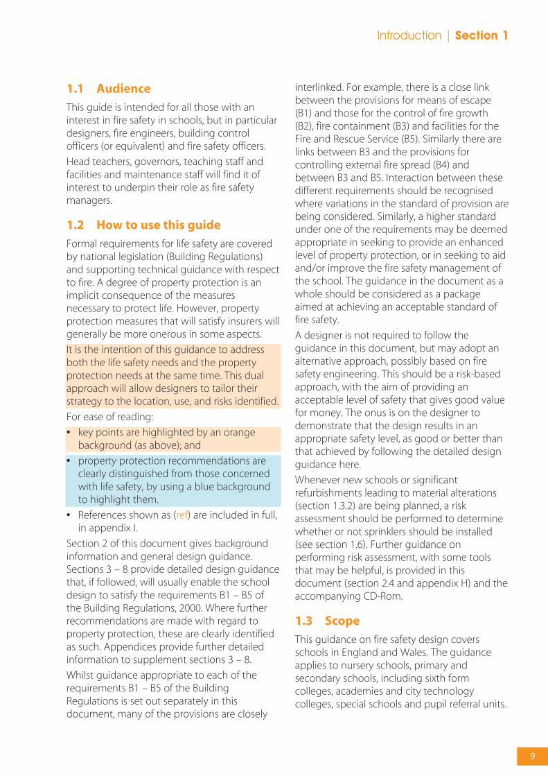
This guide is intended for all those with aninterest in fire safety in schools, but in particulardesigners, fire engineers, building controlofficers (or equivalent) and fire safety officers.
Head teachers, governors, teaching staff andfacilities and maintenance staff will find it ofinterest to underpin their role as fire safetymanagers.
1.2 How to use this guide
Formal requirements for life safety are coveredby national legislation (Building Regulations)and supporting technical guidance with respectto fire. A degree of property protection is animplicit consequence of the measuresnecessary to protect life. However, propertyprotection measures that will satisfy insurers willgenerally be more onerous in some aspects.
It is the intention of this guidance to addressboth the life safety needs and the propertyprotection needs at the same time. This dualapproach will allow designers to tailor theirstrategy to the location, use, and risks identified.
For ease of reading:
• key points are highlighted by an orangebackground (as above); and
• property protection recommendations areclearly distinguished from those concernedwith life safety, by using a blue backgroundto highlight them.
• References shown as (ref) are included in full,in appendix I.
Section 2 of this document gives backgroundinformation and general design guidance.Sections 3 – 8 provide detailed design guidancethat, if followed, will usually enable the schooldesign to satisfy the requirements B1 – B5 ofthe Building Regulations, 2000. Where furtherrecommendations are made with regard toproperty protection, these are clearly identifiedas such. Appendices provide further detailedinformation to supplement sections 3 – 8.
Whilst guidance appropriate to each of therequirements B1 – B5 of the BuildingRegulations is set out separately in thisdocument, many of the provisions are closely
interlinked. For example, there is a close linkbetween the provisions for means of escape(B1) and those for the control of fire growth(B2), fire containment (B3) and facilities for theFire and Rescue Service (B5). Similarly there arelinks between B3 and the provisions forcontrolling external fire spread (B4) andbetween B3 and B5. Interaction between thesedifferent requirements should be recognisedwhere variations in the standard of provision arebeing considered. Similarly, a higher standardunder one of the requirements may be deemedappropriate in seeking to provide an enhancedlevel of property protection, or in seeking to aidand/or improve the fire safety management ofthe school. The guidance in the document as awhole should be considered as a packageaimed at achieving an acceptable standard offire safety.
A designer is not required to follow theguidance in this document, but may adopt analternative approach, possibly based on firesafety engineering. This should be a risk-basedapproach, with the aim of providing anacceptable level of safety that gives good valuefor money. The onus is on the designer todemonstrate that the design results in anappropriate safety level, as good or better thanthat achieved by following the detailed designguidance here.
Whenever new schools or significantrefurbishments leading to material alterations(section 1.3.2) are being planned, a riskassessment should be performed to determinewhether or not sprinklers should be installed(see section 1.6). Further guidance onperforming risk assessment, with some toolsthat may be helpful, is provided in thisdocument (section 2.4 and appendix H) and theaccompanying CD-Rom.
1.3 Scope
This guidance on fire safety design coversschools in England and Wales. The guidanceapplies to nursery schools, primary andsecondary schools, including sixth formcolleges, academies and city technologycolleges, special schools and pupil referral units.

Section 1 | Introduction
Sixth form colleges designated as Institutions of Further Education are covered by ApprovedDocument B (AD B) but BB 100 provides usefulsupplementary guidance on the design ofeducational buildings for students up to theage of 19.
This guide covers compliance withrequirements B1 to B5 of the BuildingRegulations 2000 (which is concerned with lifesafety) but also provides guidance on thedesign of school buildings to reduce arson andproperty loss through fire.
1.3.1 Limitations to the scope
In order to produce a more manageabledocument, some circumstances less commonin schools have not been covered in detail. Ifany of these cases apply, the designer shouldconsult AD B for guidance. As the 2006 revisionof AD B was drafted on the understanding thatschools would be covered by BB 100 (thisdocument), schools are not listed in thePurpose Groups covered by AD B. In most casesthe appropriate purpose group will be 5(Assembly & Recreation), or 2a if residentialaccommodation is involved.
The following buildings are not covered by thisdocument:
• Buildings which include residentialaccommodation.
• Buildings with a top floor higher than 18m.
• Buildings with a basement deeper than 10m.
• Car parks (including those as part of theschool building).
1.3.2 Material alteration
A ‘material alteration’ is one which, at any stageof the work, results in a building being lesssatisfactory than it was before in relation tocompliance with the requirements of Parts B1,B3, B4 or B5 of the Building Regulations.Regulation 4(1) requires that any building workcarried out in relation to a material alterationcomplies with the applicable requirements ofSchedule 1 to the Regulations, while Regulation4(2) requires that once that building work hasbeen completed, the building as a whole mustcomply with the relevant requirements of
Schedule 1 or, where it did not comply before,must be no more unsatisfactory than it wasbefore the work was carried out.
1.3.3 Buildings of special architectural orhistoric interest
In some cases where alterations to existingbuildings are planned, particularly in buildingsof special architectural or historic interest,adherence to the detailed design guidance inthis document might prove unduly restrictive.In such cases it would be appropriate to takeinto account a range of fire safety features,some of which are dealt with in this documentand some of which are not addressed in anydetail and to set these against an assessment ofthe hazard and risk peculiar to the particularcase.
1.4 Legal requirements
1.4.1 Building Regulations
Since April 2001, all new building work inschools has been subject to approval under theBuilding Regulations.
The functional requirements B1 to B5 ofSchedule 1 of the Building Regulations are asfollows:
B1: To ensure satisfactory provision of means ofgiving an alarm of fire and a satisfactorystandard of means of escape for persons in theevent of fire in a building.
B2: To ensure fire spread over the internallinings of buildings is inhibited.
B3: To ensure the stability of buildings in theevent of fire; to ensure that there is a sufficientdegree of fire separation within buildings andbetween adjoining buildings; to provideautomatic fire suppression where necessary;and to inhibit the unseen spread of fire andsmoke in concealed spaces in buildings.
B4: To ensure external walls and roofs haveadequate resistance to the spread of fire overthe external envelope and that spread of firefrom one building to another is restricted.
B5: To ensure satisfactory access for fireappliances to buildings and the provision of
10

Introduction | Section 1
facilities in buildings to assist fire-fighters in thesaving of life of people in and around buildings.
In this document, each of the Requirements isdealt with separately in one of sections 4 – 8.The Requirement is reproduced at the start ofthe relevant section, followed by anintroduction to the subject, and the detaileddesign guidance.
Any building work which is subject to therequirements imposed by Schedule 1 of theBuilding Regulations should, in accordance withRegulation 7, be carried out with propermaterials and in a workmanlike manner. Furtherguidance can be found in the ApprovedDocument supporting Regulation 7 onmaterials and workmanship.
Regulation 16B requires that where buildingwork is carried out which affects fire safety, andwhere the building affected will be covered bythe Regulatory Reform (Fire Safety) (RRO) Order2005, the person carrying out the work mustprovide sufficient information for persons tooperate and maintain the building inreasonable safety. This information will assist theeventual owner/ occupier/employer to meettheir statutory duties under the RegulatoryReform (Fire Safety) Order. Appendix G providesadvice on the sort of information that should beprovided.
1.4.2 Interaction with other legislation
Under the Regulatory Reform (Fire Safety) Order2005 (RRO) implemented in October 2006, firesafety legislation has become simplified and asuite of guides has been prepared for differentoccupancies. These deal with the provision andmanagement of fire safety by risk assessment inthe whole range of existing buildings; the onefor schools is covered in Risk Assessment Guidefor Educational Premises 2006 (RRO Guide).
The Department for Children, Schools andFamilies document Health & Safety:Responsibilities and Powers (DfES/0803/2001)clarifies responsibilities for schools underexisting health and safety legislation. Withschools that are maintained by the LocalAuthority (LA), responsibility for fire safety isusually shared between the authority, thegoverning body and the head teacher. The LA
usually has responsibility for alarm systems andthe structural fire integrity of buildings, whilethe governing body and the head teacher areresponsible for the day-to-day running of theschool and the management of all systemsincluding those for fire safety.
All three parties must ensure that schoolpremises comply with Regulation 17 of TheEducation (School Premises) Regulations 1999.This requires that every part of a schoolbuilding, and of the land provided for a school,shall be such that the safe escape of theoccupants in case of fire is reasonably assured.
Particular regard is given to:
• the likely rate at which flames will spreadacross exposed surfaces;
• resistance to fire of the structure and of thematerials of which the structures are madeand their properties; and
• the means of escape in the case of fire.
1.5 Inclusive design
Current accommodation needs of schoolbuildings must address inclusion where a wideage range of pupils may attend full time andalso during community use where the buildingsmay be used out-of-hours by many groups,regardless of disability, age or gender.
Buildings and their facilities should beaccessible to all who may work or live in themor visit them, without discrimination and it islikely that just as the requirements of AD MAccess and facilities for disabled people and BS8300:2001 Design of buildings and theirapproaches to meet the needs of disabled peoplehave been drafted in response to the needs ofthe physically and visually impaired, the needsof the most disadvantaged will continue toinfluence future design standards.
Whilst there are obligations under the DisabilityDiscrimination Act 1995 for service providers andemployers to facilitate accessibility, there areparticular issues attending pupils in wheelchairsand those with multiple difficulties, and Specialor Complex Needs in terms of generalcirculation and safe movement through andaround buildings.
11

Section 1 | Introduction
Some children with Special Needs use largerwheelchairs with additional support frames andother mobility aids which will impact on doorand corridor widths over and above thoserequired by AD M and BS:8300:2001 forhorizontal escape. Places of safety/refuges willneed to be planned and provided (BS5588:Part8) to accommodate attendants if necessary,until the person can be escorted out of thebuilding.
Those with audio/visual impairment and otherswith language difficulties may not be able tohear or read warnings, therefore in addition toconventional emergency signage, emergencyroutes may need to be highlighted by colourand texture changes on walls and floors.
The fire safety aspects of the BuildingRegulations Approved Document Part B areextended to schools in this document andfurther extended in detail in BB 77, Designing forPupils with Special Educational Needs andDisabilities, to ensure that fire safety measuresincorporated into a building take into accountthe access needs of all.
1.5.1 Out-of-hours use
With the increasing use of school buildings forcommunity, or part-time use throughout theday and evening, the designer will need to caterfor extended use very carefully, particularly for arefurbishment scheme. The use of only part ofthe building for community use (wherealternative evacuation routes may be locked forschool security reasons) along with the need totrain a Responsible Person for day and eveningactivity is also an issue that needs to beaddressed.
The major impact of the extended use is thatthe occupants of the building during theseperiods are less familiar with the layout andfacilities than the daytime pupils are. As aconsequence the escape plans and provisionsmust accommodate this change in occupancyeven down to whether designated assemblypoints are adequate. Thus extended use willprobably require the provision of:
• increased lighting, especially emergencylighting and external lighting;
• changes in evacuation planning andoperation;
• increased car parking with attendantconcerns about opportunities for vandalismand arson; and
• changes in door hardware selection.
1.6 DCSF policy regarding sprinkler systems
Sprinkler systems installed in buildings cansignificantly reduce the degree of damagecaused by fire and can reduce the risk to life.
On 1 March 2007, DCSF announced the newpolicy on sprinklers and their value as a measureagainst the risk of fire and arson. All new schoolsshould have fire sprinklers installed except in afew low risk schools.
Although the provision of sprinklers is not arequirement of the Building Regulations, DCSFexpects that the Education Authority, FundingBody or overall ‘client’ of the scheme, shouldrequest, as part of the Employer's Requirements,that a risk assessment be undertaken to assessthe validity of providing sprinklers in thescheme.
To help clients, local authorities and designteams assess the level of risk and make the rightdecisions, the DCSF has developed two newpractical aids. The first is an interactive fire riskassessment tool. DCSF expects that this riskanalysis will always be carried out and newschools being planned that score medium orhigh risk using the risk analysis tool will havesprinklers fitted.
The second tool is a cost benefit analysis tool.This tool helps users decide whether sprinklersrepresent good value for money.
These tools are included in a CD-Rom with thispublication. Version updates will be publishedby DCSF on their fire safety websitewww.teachernet.gov.uk/fire
See section 2.4, and appendix H later.
12
Introduction | Section 1
1.7 Property protection
Figures from the Department for Communitiesand Local Government (CLG) show that over1300 school fires a year in England and Walesare attended by local authority Fire and RescueServices. Around 60% of these are starteddeliberately. For more statistics on school fires,see section 2.2. It is necessary to greatly reducethe risk of fires occurring in schools and, when afire does occur, reduce the risk of it spreading.
While the primary concern is for the safety ofthe users of school buildings, a fire can have aserious impact on children’s education due todisruption and loss of course work. Theimportant roles that schools play in thecommunity mean that losses incurred as aresult of fire can have particularly severe socialconsequences. As such, it is important thatproperty protection be considered during thedesign and throughout the working life of thesebuildings. This guide therefore gives advice onproperty protection as well as life safety issues.
For the purposes of this guide, the objectives ofproperty fire protection include:
• minimising the effects of fire on theoperation of the school (primarily, teaching);
• limiting the effects of interruption tooperation of the school;
• seeking to have the school operationalwithin 24 hours; and
• protecting the buildings.
While all of these objectives can be achievedonly if the damage to the school from fire orsmoke is minimised, it is also necessary forcontingency plans to be in place to restoreoperations.
The insurance industry, Zurich Municipal, theArson Prevention Bureau and the Arson ControlForum have produced various guides whichaddress arson and vandalism and are directedat property protection (refs).
The principles recommended by the insuranceindustry for property protection are:
• construct the building from materials thatwill not contribute to a fire (except joinery);
• prevent premature collapse or excessivedeflection;
• construct the building to minimise fire andsmoke spread and confine the fire to itssource;
• seek to minimise the risk of arson;
• design the building to avoid fire spread fromanother building or an external fire;
• provide appropriate automatic fire detectionand alarm systems;
• ensure safety systems are maintained;
• ensure an adequate standard of fire safetymanagement;
• seek to minimise the potential damage fromfire-fighting water to the building (and theenvironment);
• ensure that all appropriate products orsystems are third-party approved;
• ensure that all installers are third-partyapproved; and
• ensure that all heat-producing equipment, orequipment which might otherwise start afire, is properly designed, installed andmaintained.
In addition most insurers would recommendproviding sprinklers for property protection.
Further information can be obtained from theFPA website: www.thefpa.co.uk
13

Section 1 | Introduction
Many insurers use the Fire ProtectionAssociation’s (FPA) Design Guide for the fireprotection of buildings (ref) as a basis forproviding guidance to the building designer onwhat they require. Some of the ways that thedesigner can reduce the effects of a fire usingpassive fire protection are by:
• limiting the use of easily ignited materials inthe construction;
• using fire-resisting elements of construction(loadbearing and non-loadbearing);
• using smoke restricting elements ofconstruction;
• providing features that limit the likely spreadof flames and smoke production;
• providing features that prevent or limit fireand smoke exploiting cavities;
• preventing fire from exploiting services orventilation ductwork; and
• limiting the potential for spread of fire to anadjacent building.
1.8 Alternative approaches – ‘firesafety engineering’
Fire safety engineering can provide analternative approach to fire safety. It may be theonly practical way to achieve a satisfactorystandard of fire safety as school building usagebecomes ever more flexible in response to theneeds of the local community. Fire safetyengineering may also be suitable for solving aproblem with an aspect of the building designwhich otherwise follows the provisions in thisdocument.
Fire safety engineering is a risk-based approachand should provide a flexible way of solving thedesign problems and management issues. Thefire safety strategy for the building may alsoinclude the level of management needed.
British Standard BS 7974 Fire safety engineering inbuildings and supporting Published Documentsprovide a framework and guidance on thedesign and assessment of fire safety measuresin buildings. Following the discipline of BS 7974should enable designers and Building ControlBodies to be aware of the relevant issues, the
need to consider the complete fire-safetysystem and to follow a disciplined analyticalframework.
Design teams must allocate time to consultwith enforcing bodies and property insurers atan early stage to balance the requirements forlife safety and recommendations for propertyprotection.
For further information, refer to section 2.3.
1.9 Independent schemes ofcertification and accreditation
The performance of a system, product,component or structure is dependent uponsatisfactory site installation, testing andmaintenance. Independent schemes ofcertification and accreditation of installers andmaintenance firms will provide confidence inthe appropriate standard of workmanship beingprovided.
Confidence that the required level ofperformance can be achieved will bedemonstrated by the use of a system, material,product or structure which is provided underthe arrangements of a product conformitycertification scheme and an accreditation ofinstallers scheme.
Third party accredited product conformitycertification schemes provide a means ofidentifying materials and designs of systems,products or structures which havedemonstrated that they have the requisiteperformance in fire. In addition they provideconfidence that the systems, materials, productsor structures actually supplied are provided tothe same specification or design as thattested/assessed.
Third party accreditation of installers of systems,materials, products or structures provides ameans of ensuring that installations have beenconducted by knowledgeable contractors toappropriate standards, thereby increasing thereliability of the anticipated performance in fire.
Building Control Bodies may accept thecertification of products, components, materialsor structures under such schemes as evidenceof compliance with the relevant standard.
14

15
Similarly, Building Control Bodies may acceptthe certification of the installation ormaintenance of products, components,materials or structures under such schemes asevidence of compliance with the relevantstandard. Nonetheless, a Building Control Bodywill wish to establish, in advance of the work,that any such scheme is adequate for thepurposes of the Building Regulations.
Insurers may require independent schemes ofcertification and accreditation of installers of asystem, product, component or structure for thepurposes of property protection.
Many certification bodies which approve suchschemes are accredited by UKAS.
1.10 Fire safety management
Building Regulations do not impose anyrequirements on the fire safety management ofa building. However, in developing anappropriate fire safety design for a building itmay be necessary to consider the way in whichit will be managed. A design which relies on anunrealistic or unsustainable managementregime cannot be considered to have met therequirements of the Regulations.
This guidance has been written on theassumption that the building concerned will beproperly managed. The use of the school willneed to be flexible to respond to the changingneeds of the occupants. A clear fire strategyreport must be available on site; this willincorporate the management principles of thebuilding with respect to fire.
Once the building is in use the managementregime should be maintained and any variationin that regime should be the subject of asuitable risk assessment. Failure to take propermanagement responsibility may result in theprosecution of an employer, building owner oroccupier under legislation such as theRegulatory Reform (Fire Safety) Order 2005.
1.10.1 The DCSF risk managementstrategy for schools and localauthorities
In May 2007, DCSF launched a risk managementstrategy for existing schools and localauthorities. It aims to improve risk management,school safety and security and help schools savemoney on their insurance premiums. Thestrategy includes a diagnostic risk ranking toolthat enables local authorities to assess levels ofrisk in existing schools. Using this data,authorities can work towards weighting ordiscounting school insurance premiums as afinancial incentive for schools to manage theirrisks. A risk management toolkit complementsthe risk ranking database and weightedpremium approach. Seewww.dfes.gov.uk/riskmanagement orwww.teachernet.gov.uk/riskmanagement
Introduction | Section 1
Section 2Backgroundinformation

17
Background information | Section 2
Section 2 of this document gives backgroundinformation and general design guidance.
Section 2.1 provides the basis for understandingwhy fires develop and spread and how smokemoves through the building. It then outlineshow to minimise the growth and spread of thefire thus allowing pupils and staff to leave safely.Section 2.2 provides statistical data related toschool fires, which helps to give anunderstanding of the scale of the problems. Thisinformation will also be directly relevant to firerisk assessments.
A designer is not required to follow the detaileddesign guidance in sections 3 – 8, but mayadopt an alternative approach, possibly basedon fire safety engineering. This is a risk-basedapproach, with the aim of providing anacceptable level of safety that gives good valuefor money. The onus is on the designer todemonstrate that the design results in anappropriate safety level, as good or better thanthat achieved by following the detailed designguidance. An outline of the fire safetyengineering process is given in section 2.3, andrisk assessment and cost-benefit analysis areboth briefly covered in section 2.4.
A design based on fire safety engineering mayinvolve various protection methods and firesafety systems. These are briefly described insection 2.5, with cross-reference to othersections of this document and pointers tofurther information.
Arson is a particular problem for schools. Manyarson attacks will be opportunistic andtherefore whilst the removal of likely fuel,rubbish, etc will reduce the possibility of anignition occurring, even the best design will notcounter the efforts of the really determinedarsonist. There are several strategies for makingtheir efforts less effective. These are discussed insection 2.6.
The guidance in sections 3 – 8 has been writtenon the assumption that the building concernedwill be properly managed. The principles of firesafety management are summarised in section2.7 so that the designer can seek to ensure thatthe built school can be managed safely andeffectively.
2.1 The principles of fire behaviour
2.1.1 How do fires start?
The Fire Triangle (figure 1) represents the threeelements needed for a fire to develop, namely afuel which can be ignited by a heat source inthe presence of oxygen from the air. Control ofthe fire is by eliminating one of the threeelements. Identifying fire hazards includesrecognising the fuel load and whether there areany heat sources present, eg, in kitchens andlaboratories.
A fire can start when a source of (sufficient) heatis brought into contact with a combustiblematerial (or flammable liquid) in the presence ofair (oxygen).
Sources of heat include smokers’ materials (inparticular, lit matches, but also smoulderingcigarettes), other naked flames (such as candlesor gas cooker flames), overheating or sparkingelectrical equipment, chemical reactions,overheating motors, lightning, focussed solarrays, and many others.
In schools, combustible materials abound; suchas paper, cloth and furnishings. Kitchens,workshops and laboratories may containflammable liquids (such as cooking oil) orchemicals. Air is, of course, all around us.
Figure 1 The Fire Triangle

18
Section 2 | Background information
2.1.2 Where do fires start?
Fire can start anywhere. Accidental fires can startwhen faulty over-heating electrical equipment, forexample, is in contact with combustible material.They can therefore start anywhere, but they usuallystart inside a room. They should seldom start onescape routes, since fire safety managementshould ensure that these are kept clear.
Deliberate (arson) fires can be started anywhere,and often in places out of view, both inside andoutside the building.
2.1.3 How do fires develop and spread?
When the fire starts in an enclosed space, hotsmoke-laden gases will rise to the ceiling and forma layer which will flow under the whole ceiling atfirst and if not controlled it will then deepen andeventually fill the whole space. This is known as’smoke-logging’. As the fire grows in area, flamesand radiated heat will spread to any combustiblematerials such as fittings, furniture, exposedpapers, etc. The flames will grow in length,increasing in height until they reach the ceilingwhere they will be deflected horizontally. Heat willthen be radiated downwards which acceleratesthe growth of the fire as other items becomeinvolved in the fire leading to full involvement, ie,flashover. If there is little fresh air getting into thespace the rate of fire development will slow asthere is less oxygen present to keep the fire going.The gases generated will be very toxic and high incarbon monoxide.
This smoke will be irritant, asphyxiant and toxic,causing coughing, streaming eyes and difficultyin breathing. It will also be dense, and willrestrict vision rapidly, resulting in disorientationand difficulty in moving away from the fire-affected area. The radiation from the flames oncethey reach the ceiling will promote fire growth.Any material which is burning will be hot andwill use up the oxygen present and will producecarbon monoxide which will also disorientanyone in the area.
So, a fire starting in a compartment in a buildingmay not only put anyone present in the room oforigin at risk from the effects of the combustionproducts but if uncontrolled it will spread toother parts of the building as well. This couldjeopardise the safety of people remote from
where the fire started and could also causedamage over a wide area.
Thus schools should be designed, maintainedand managed to reduce fire spread.
2.1.4 Smoke movement and its impact onescape
Early on in the fire, the most critical effects onthe occupants will be from the smoke and otherproducts of combustion. Smoke is often the firstthing to be noticed by the occupants and isgenerally the cause of the first alarm. In theabsence of any strong air currents smoke tendsto gather at ceiling level, filling the space fromthe top down, ie, smoke logging. Once down tohead height people will not be able to see veryfar because of the density of the smoke and theunpleasant effect on their eyes. Breathing will bedifficult, as the carbon dioxide levels increase sothe breathing rate goes up and more smoke istaken in which will be increasingly short ofoxygen. The effects will be felt very quickly byyounger pupils, who breathe quite rapidlyanyway; leading to respiratory distress becausethe smoke is hot and eventually tounconsciousness or death as a result of carbonmonoxide poisoning.
Recognition of these circumstances is essentialwhen dealing with different age groups whomay be familiar with the building but may notbe very mobile for a variety of reasons.Legislative controls are usually cast with adults inmind. Although compliance can be achieved foradult occupants, designers and users of schoolbuildings do need to consider the younger,smaller and shorter pupils at the planning stageto allow everyone, regardless of age, size anddisability to leave safely.
It is important, therefore, that the escape routesmust be protected against smoke penetrationand the storey or final exit must be reachedbefore they become untenable. Once visibilityhas dropped below 10m it will be difficult tomove safely to the exits. The time taken will alsoneed to take account of such things as thefurniture present and the size of exits and theage and mobility of the occupants.
Thus all the right measures must be in place toallow safe egress from any part of the building.

19
Background information | Section 2
Figure 2 Number of accidental and non-accidental fires in schools – Source: CLG Fire Statistics 1993-2005
2.2 Statistical data for school fires
DCSF intend to provide links to updatedstatistical information on school fires (such asthat presented below), via their fire safetywebsite.
The estimated number of accidental and non-accidental fires attended by Local Authority Fireand Rescue Services between 1993 and 2005 isshown in figure 2 (source: Department forCommunities and Local Government (CLG) FireStatistics).
1993 1994 1995 1996 1997 1998 1999 2000 2001 2002
1800
1600
1400
1200
1000
800
600
400
200
2003 2004 2005
Accidental
Non-accidental
Num
ber
of f
ires
2.2.1 Deaths
The number of deaths in school fires is verysmall.
During the period 1994-2002, only one persondied, in approximately 14,700 fires. The casualtywas a 56-year old man, who died from burns.He was found in the place of fire origin (the roofspace) where he had been working with a blowlamp (or similar heat source). The fire occurredat about 14:45 on Saturday 22 February 1997(Gamble 1994-2002).
Despite the statistics, it is important to avoidcomplacency; there is always the possibility of adeath in a school fire or even multiple deaths.
2.2.2 Injuries
The number of injuries in school fires is alsoquite small. During the period 1994-2002, 461people were injured, an average of 51 per year,and 0.03 injuries per fire. Not all injuries aresevere. In 2002, there were 46 injuries, asfollows:
• 14 people suffering from smoke inhalation;
• 5 people suffering from burns;
• 4 people suffering from physical injuries(cuts, sprains, abrasions, etc);
• 2 people suffering from shock;
• 2 people suffering from other injuries; and
• 19 people referred to hospital forprecautionary checks.
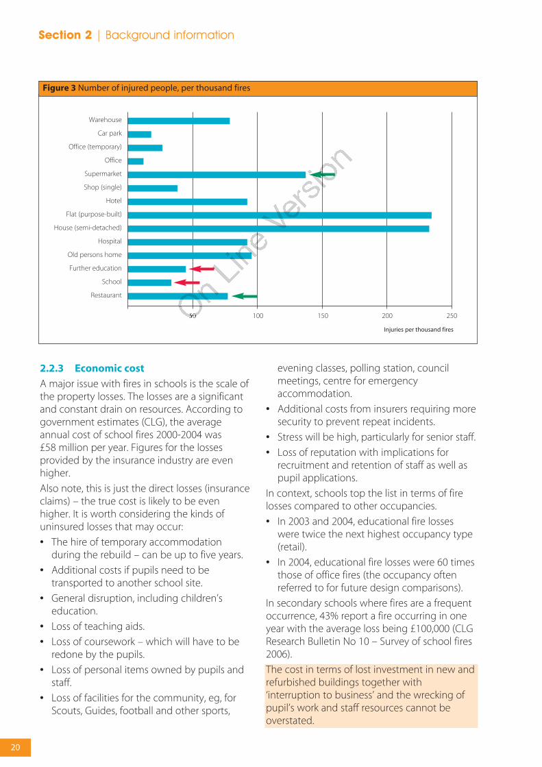
It is possible to put the injury rate per fire intocontext, by considering different building types.The worst fires are in dwellings which is not thatsurprising. Schools and Further Education(highlighted by red arrows in figure 3) are lowrisk (for life safety) compared to other buildingpurpose groups. Some other purpose groupsthat one would not consider high risk, eg,supermarkets and restaurants (highlighted bygreen arrows in figure 3), are worse thanschools.
20
Section 2 | Background information
2.2.3 Economic cost
A major issue with fires in schools is the scale ofthe property losses. The losses are a significantand constant drain on resources. According togovernment estimates (CLG), the averageannual cost of school fires 2000-2004 was £58 million per year. Figures for the lossesprovided by the insurance industry are evenhigher.
Also note, this is just the direct losses (insuranceclaims) – the true cost is likely to be evenhigher. It is worth considering the kinds ofuninsured losses that may occur:
• The hire of temporary accommodationduring the rebuild – can be up to five years.
• Additional costs if pupils need to betransported to another school site.
• General disruption, including children’seducation.
• Loss of teaching aids.
• Loss of coursework – which will have to beredone by the pupils.
• Loss of personal items owned by pupils andstaff.
• Loss of facilities for the community, eg, forScouts, Guides, football and other sports,
evening classes, polling station, councilmeetings, centre for emergencyaccommodation.
• Additional costs from insurers requiring moresecurity to prevent repeat incidents.
• Stress will be high, particularly for senior staff.
• Loss of reputation with implications forrecruitment and retention of staff as well aspupil applications.
In context, schools top the list in terms of firelosses compared to other occupancies.
• In 2003 and 2004, educational fire losseswere twice the next highest occupancy type(retail).
• In 2004, educational fire losses were 60 timesthose of office fires (the occupancy oftenreferred to for future design comparisons).
In secondary schools where fires are a frequentoccurrence, 43% report a fire occurring in oneyear with the average loss being £100,000 (CLGResearch Bulletin No 10 – Survey of school fires2006).
The cost in terms of lost investment in new andrefurbished buildings together with‘interruption to business’ and the wrecking ofpupil’s work and staff resources cannot beoverstated.
Figure 3 Number of injured people, per thousand fires
Warehouse
Car park
Office (temporary)
Office
Supermarket
Shop (single)
Hotel
Flat (purpose-built)
House (semi-detached)
Hospital
Old persons home
Further education
School
Restaurant
50 100 150 200 250
Injuries per thousand fires

21
Background information | Section 2
2.2.4 Pattern of accidental and deliberatefires
According to CLG statistics for the years 2000-2005, there have been just over 1,300 fires peryear on average over this period. 56% of thesefires were classified as 'non-accidental', with themajority of these likely to have been arson.
Received wisdom was that deliberate fires occurwhen the school is unoccupied so there is a lowrisk to life apart from to those lighting the firesand to fire-fighters. However, the perception isthat this is now changing, with up to a third of
deliberate fires starting during the school day. Therisk to pupils can be high with the younger pupilsdependent on teachers and other staff for theirsafety in the event of fire. Typically, however, thelarger fires still occur out of hours when theschool is closed and the fire setter can workundisturbed and/or there is a delay in discovery.
Figure 4 shows the pattern of accidental andnon-accidental fires during the day. This trendhas remained fairly constant over the yearsstudied, which suggests that the perception hasonly recently come into line with the reality.
Figure 4 Number of accidental and non-accidental fires occurring at different times of day
1 2 3 4 5 6 7 8 9 10
140
120
100
80
60
40
20
11 12 13 14 15 16 17 18 19 20 21 22 23 24
Hour of day
Accidental
Non-accidental
Num
ber
of f
ires
Figure 5 School fires per million population for different Fire and Rescue Service areas
Avon
80
70
60
50
40
30
20
10
BedsBerks
Bucks
Cambs
Cheshire
Clevelan
d
Cornwall
Cumbria
Derbys
hire
Devon
Dorset
Durham
East S
ussex
Essex
Glos
Hants
Herefo
rd &
Worcs
Herts
Humbersi
de
I O W
ightKent
Lancs
Leics
Lincs
Norfolk
N Yorks
Northan
tsNotts
Oxon
Som
erset
Staff
s
Suffo
lk
Surre
y
Warw
icks
West
Susse
xW
ilts
Gtr M
anch
ester
Merse
y
South
Yorks
Tyne &
Wear
West
Mid
West
Yorks
London 1
London 2
London 3
North W
ales
Mid W
ales
South
Wale
s
Northern
Irelan
d
Strat
hclyde
Highland
Grampian
Taysid
e
Loth
ian Fife
Average for thewhole country(1382 fires per 58 million people)
Fire
s p
er m
illio
n p
opul
atio
n

22
Section 2 | Background information
2.2.5 Relative number of school fires indifferent regions of the country
Figure 5 shows the number of school fires permillion head of population, for each of the Fireand Rescue Service areas in the UK. Note thatthere is considerable variation betweendifferent regions. CLG (Fire Statistics, UnitedKingdom, 2004, CLG February 2006) indicatethat 40% of school fires occur in themetropolitan areas.
This factor is one of those that should beconsidered when performing a risk assessmentfor a particular school project.
2.2.6 Fire locations within a school
The relative number of reported fires (CLG firestatistics 2002) starting in different room types isshown in figure 6. Note that some areas ofspecial fire hazard (eg, heat bays) do not appearwithin this pie chart, partly because such roomsare relatively few in number, and partly becauseextra fire safety precautions (eg, extinguishers)will have been provided, enabling fires to bedealt with while they are still small, and thus not
requiring Fire and Rescue Service intervention.Note the relatively large number of cloakroomand toilet fires, most of which are arson.
This information can be used as part of aquantified risk assessment, to estimate thefrequency of fires starting in different room types.
2.3 Fire safety engineering
The definition of fire safety engineering used bythe Institution of Fire Engineers is:
‘The application of scientific and engineeringprinciples based on an understanding of thephenomena and effects of fire and of thebehaviour of people to fire, to protect people,property and the environment from the destructiveeffects of fire.’
Other organisations, such as ISO, have publishedsimilar definitions (see, eg, ISO TR 13387).
The principal objective of fire engineering is,when fire occurs, to provide an acceptable levelof safety. Often this will involve calculation ormodelling of scenarios affecting all or part ofthe fire ‘system’.
Fire safety engineering is a risk-based approachand should provide a flexible and cost-effectiveway of solving the design problems andmanagement issues. It requires taking a moreholistic approach to a problem than may betaken when using more prescriptive methods.Additional factors, covered implicitly in theprescriptive approach, need to be consideredexplicitly.
It is often the interactions between differentaspects that cause difficulties in practicalsituations. Solutions to problems of a building'sday-to-day use (ventilation, structural, security,etc) may conflict with requirements for firesafety. Fire safety engineering must beundertaken using a systematic approach toavoid potentially life-threatening omissions inthe analysis. The flow diagram (figure 7) outlinesa suggested approach to the design process,following BS7974 (2001): Application of fire safetyengineering principles to the design of buildings –Code of practice.
Fire safety engineering will be most effective if itis included in the overall design process at theearliest possible opportunity. It should also be
Figure 6 relative number of reported fires starting indifferent room types
Class room
Cloakroom/toilets
Store room
Kitchen/canteen
Circulation spaces
Boiler/plant room
Main hall/place of assembly
Office
Sports halls/changing
Laboratory
Other special hazard areas
Other areas

23
Background information | Section 2
emphasised that the process is iterative,continuing throughout the overall designprocess until the design is complete.
The key stages are:
• the qualitative design review (QDR);
• the quantitative analysis;
• the assessment; and
• reporting.
Here, particularly at the qualitative designreview stage, the interaction of all the buildingsystems are considered as well as the detailedperformance of the fire protection systems. Awide variety of measures could be consideredand incorporated to a greater or lesser extent,as appropriate in the circumstances.
These include:
• the adequacy of means to prevent fire;
• early fire warning by an automatic detectionand warning system;
• the standard of means of escape;
• the standard of active measures for fireextinguishment or control;
• provision of smoke control;
• control of the rate of growth of a fire;
• structural robustness and the adequacy ofthe structure to resist the effects of a fire;
• the degree of fire containment;
• fire separation between buildings or parts ofbuildings;
• facilities to assist the Fire and Rescue Service;
• availability of powers to require staff trainingin fire safety and fire routines;
• consideration of the availability of anycontinuing control under other legislationthat could ensure continued maintenance ofsuch systems; and
• management.
The QDR, assessment and reporting arediscussed in the following sections. Thequantitative analysis is not covered here, as therange of possible calculations is too wide (it isthe role of the QDR to decide whichcalculations are appropriate for a given project).The assumptions made when quantitativemethods are used need careful assessment.
2.3.1 Qualitative design review
The fire safety design process begins with thequalitative design review (QDR). During thisstage the scope and objectives of the fire safetydesign are defined, and performance criteria areestablished. One or more potential designs willbe considered, for a detailed quantitativeassessment. If the proposed design(s) areunsatisfactory according to the performancecriteria chosen, the QDR must be repeated andnew or modified designs will need to beconsidered.
Figure 7 Flow chart illustrating the basic designprocess, following BS 7974
Start
No
Compare results with acceptance criteria
Report and present results
Yes
Modify design
Qualitative design review(QDR)
Does trial design pass criteria?
Quantified analysis

24
Section 2 | Background information
Tasks carried out in the QDR include:
• review of the architectural design;
• determine building, environment andoccupant characteristics;
• establish fire safety/protection objectives;
• decide acceptance criteria;
• identify fire hazards and possibleconsequences;
• propose trial fire safety/protection designs;
• propose an evacuation strategy;
• make reasonable assumptions to simplify theproblem;
• specify scenarios for analysis;
• indicate appropriate methods of analysis; and
• report the results of the QDR stage.
For large projects, the QDR should beperformed by a group of people, includingmembers of the design team, one or more firesafety engineers, and others as appropriate(such as Building Control Bodies andrepresentatives of the fire service and insurers).The results of the QDR should be included inthe final design report seeking approval of thedesign.
2.3.2 Assessment of designs
In a fire safety engineering design following theprocedures given in BS7974, the assessment ofa design requires the results of a quantifiedanalysis to be compared with the originaldesign criteria determined during thequalitative design review (QDR). The assessmentmethod and criteria should be agreed beforethe quantitative design stage.
Factors that should be taken into accountinclude:
• the anticipated probability of a fire occurring;
• the anticipated fire severity;
• the ability of a structure to resist the spreadof fire and smoke; and
• the consequential danger to people in andaround the building.
BS7974 gives three methods of assessing adesign:
• Comparative criteria where a design is shownto have a comparable level of safety to someother method (eg, Approved Document B,for buildings in England and Wales).
• Deterministic criteria where a specific set ofsafety conditions are shown to have beenachieved (eg, smoke layer is never below aspecified height). The QDR should establish aworst case fire scenario (or scenarios) for theparticular school in question and recognisethat any uncertainty in the calculationsshould be considered. It is better to err onthe side of safety if there are any doubts.
• Probabilistic criteria where the frequency ofan event occurring (ie, probability ofoccurrence during a given time period) isshown to be less than an agreed small value.The consequences of the event should alsobe considered. The risk of an event is definedby multiplying the consequence by thefrequency.
Failure of a design to meet the assessmentcriteria will require the design to be modified,and the QDR and quantitative analysis cycle tobe repeated until a successful design has beendetermined. A design should not be tailoredtoo closely to the minimum performancerequirements, as buildings change over timeand the fire strategy may have to be adapted asa result.
Trade-offs of one system for another need to becarefully evaluated as they may compromisenot only overall fire safety provisions, because ofreductions in the levels of safety back up andengineering redundancy, but also otherbuilding functions. Reductions in the level ofcompartmentation, for example, maycompromise performance in other respects(such as energy efficiency, acoustic insulation,multiple space utilisation, security, and privacy).The designer needs to take these widerconsiderations into account in the overallachievement of functional design and costtargets.

25
Background information | Section 2
2.3.3 Reporting and presentation
The design of buildings using a fire safetyengineering approach will be subject to reviewand approval and should be reported so thatthe procedures and assumptions can be readilyunderstood by a third party. Thus, assumptionsand engineering judgements should be clearlyidentified, and sufficient detail should beincluded so that the quantified analysis can berepeated or reviewed by a third party.
BS 7974 does not provide a specific format forreporting and presentation as a prescribedformat could not anticipate all the requirementsof a performance based design. It does,however state that the following should beincluded:
• objectives of the study;
• building description;
• results of the qualitative design review;
• quantified analysis;
• comparison with acceptance criteria;
• fire safety strategy;
• management requirements;
• conclusions;
• references; and
• qualifications and experience of the firesafety engineer(s).
A sensitivity or uncertainty analysis should beperformed to estimate the confidence limits forthe key output variables that provide thecomparison against the acceptance criteria.
2.4 Fire risk assessment
Any fire risk assessment should reflect the day-to-day use of the school as well as its design.
Risk assessment, either implicitly or explicitly, is akey part of building fire safety engineering. Thefinal design of the building will present a way ofdealing with the risks in a particular school, whichhave to be addressed during the life of thatbuilding. The risk assessment should not onlyexamine the chances of an incident occurring butalso the potential consequences of that incident,ie, the likelihood and impact assessed together. Itis important to match the right risk assessmentmethod to the decision to be made.
Implicit risk assessment examples include thecomparison of calculation results with thresholdcriteria, eg, ‘smoke layer well above people’sheads’ or ‘area of fire spread restricted to lessthan X m2’; often these are linked with ‘worstcase’ scenarios. The idea is that ‘worst’ and lesserscenarios lead to minimal consequences (onceremedial or protective measures have beentaken), with other more severe scenarios beingassumed to have minimal probability. However,which scenario will be ‘worst case’? Conservativeassumptions for one aspect of the fire ‘system’might not be conservative at all for otheraspects. A sensitivity analysis should beperformed to estimate the consequences ofuncertainties in the scenario, variable values, etc.
Explicit risk assessment uses the formula:
Risk = ∑ frequency x consequence
where the summation sign applies to allhazards or scenarios. For example, suppose thatthe average damage, caused when a fire occurs,is £100,000. If a fire is expected to occur onceevery 10 years on average in a particular school(ie, a frequency of 0.1 year-1), then the riskwould be £10,000/year.
Every safety decision should require a full riskanalysis, until or unless it can be shown that aless comprehensive approach is adequate. Thepreferred approach to uncertainty is to quantifyit, rather than rely on conservative assumptions.
Risks may be reduced by preventing hazardsfrom occurring (ie, reducing the frequency),from mitigating the consequences shouldhazards occur, or some combination of both.
No building can be completely safe, yet there isan unresolved question of what absolute levelof risk should be deemed acceptable. One wayin which these problems may be addressed isto make the assumption that the risksassociated with buildings designed followingprescriptive guidelines are considered to be‘reasonable’. Additionally, most quantitativemethods are used in comparative mode, ie,there is an assumption that systematic errorsand biases ‘cancel out’ when two similardesigns are compared.
26
Section 2 | Background information
2.4.1 Risk assessment and the provisionof sprinkler systems
On 1 March 2007 DCSF announced the newpolicy on sprinklers and their value as a measureagainst the risk of fire and arson. All new schoolsshould have fire sprinklers installed except in afew low risk schools.
To help clients, local authorities and designteams assess the level of risk and make the rightdecisions, the DCSF has developed two newpractical aids. The first is an interactive fire riskassessment tool. DCSF expects that this riskanalysis will always be carried out and newschools being planned that score medium orhigh risk using the risk analysis tool will havesprinklers fitted.
This tool is included in a CD-Rom with thispublication. Version updates will be publishedby DCSF on their fire safety websitewww.teachernet.gov.uk/fire
See appendix H later.
The question of whether a fire suppressionsystem such as sprinklers should be fitted willdepend on several factors all of which shouldbe identified in the risk assessment. Thesefactors include:
• probability of different fire scenarios;
• consequences of the fire scenarios;
• location of the buildings;
• how accessible they are;
• vulnerability to intruders through theperimeter of the site;
• whether there is public access to the site;
• vulnerability of the construction to fireinvolvement;
• capabilities of the security system;
• whether facilities for waste disposal andstorage are well away from the buildings toprevent an external hazard coming intocontact with the fabric of the building;
• whether there is previous history ofvandalism and arson (existing schools only);
• how long it takes the Fire and Rescue Serviceto reach the buildings and fight the fire; and
• availability of water supply.
2.4.2 Cost benefit analysis (CBA)
CBA is a logical culmination of fire safetyengineering; it enables decisions on optimisingthe balance between safety and cost to bemade. Benefits and costs need to be expressedin the same monetary terms, for example£/year. An holistic approach should ideally betaken, encompassing life safety, property orasset protection, environmental impact,business continuity, etc, and the whole life ofthe building should be considered. For aprovider of a PFI school, unavailability offacilities will be of particular concern. Somecosts are incurred at the start of the project (eg, construction/refurbishment), others areongoing (eg, maintenance). Benefits, in terms ofdeaths and injuries prevented, damageprevented or reduced, etc, would be ongoing,although factors such as reduced reliability ofprotection systems may also need inclusion.
Results of cost-benefit analysis can bepresented as either the ratio between benefitand cost (ratio > 1 is good), or the difference(benefit – cost > 0 is good). As with any aspectof fire safety engineering, theuncertainty/confidence limits in the calculationsneed to be quoted, in order to interpret thesignificance of the result. There are four possibleoutcomes:
a) Proposed measure(s) clearly beneficial (ratio> 1 or difference > 0); confidence level >95%. Note that strictly speaking the nullhypothesis is ‘measure is not cost effective’,which the analysis ‘disproves’, ie, there is lessthan a 5% probability of the analysisincorrectly giving a significant result due tochance, when really the measure is not cost-effective.
b) Proposed measures clearly not beneficial(ratio significantly < 1 or differencesignificantly < 0), confidence level << 50%.
c) Borderline (ratio ≈1 or difference ≈ 0),confidence level ≈ 50%, but with smalluncertainty (similar or smaller magnitudethan the result). In this case, if any factorshave been omitted from the analysis, theymay swing the decision one way or the otheronce they are included. Alternatively differentmeasure(s) may need to be investigated.
~
27
Background information | Section 2
d) Borderline, confidence level ≈ 50% but largeuncertainty. Here the benefit:cost ratio maybe >>1, or the difference >>0, but if theuncertainties are even larger, the cost-benefitanalysis will be of no help in reaching adecision unless the uncertainties are reduced.Alternatively other measures could beinvestigated.
The cost-benefit analysis should also take intoaccount any major knock-on effects of theproposed fire protection measures. It shouldconsider the wider consequences, particularly ifthese measures have cost implications for thebuilding as a whole regarding the overallfunctional value and sustainability of thebuilding, including its operating effectivenessand efficiency.
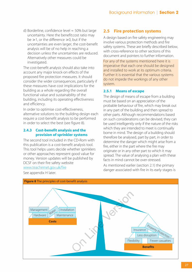
In order to optimise cost-effectiveness,alternative solutions to the building design eachrequire a cost-benefit analysis to be performedin order to select the best (see figure 8).
2.4.3 Cost-benefit analysis and theprovision of sprinkler systems
The second tool included in the CD-Rom withthis publication is a cost-benefit analysis tool.This tool helps users decide whether sprinklersor other approaches represent good value formoney. Version updates will be published byDCSF on their fire safety websitewww.teachernet.gov.uk/fire
See appendix H later.
2.5 Fire protection systems
A design based on fire safety engineering mayinvolve various protection methods and firesafety systems. These are briefly described below,with cross-reference to other sections of thisdocument and pointers to further information.
For any of the systems mentioned here it isimperative that each one should be designedand installed to work at its optimum criteria.Further it is essential that the various systemsdo not impede the workings of any othersystem.
2.5.1 Means of escape
The design of means of escape from a buildingmust be based on an appreciation of theprobable behaviour of fire, which may break outin any part of the building and then spread toother parts. Although recommendations basedon such considerations can be devised, they canbe used intelligently only if the nature of the riskswhich they are intended to meet is continuallyborne in mind. The design of a building shouldtherefore be analysed, part by part, in order todetermine the danger which might arise from afire, either in the part where the fire mayoriginate or in any other part to which it mayspread. The value of analysing a plan with thesefacts in mind cannot be over-stressed.
As mentioned earlier (section 2.1) the primarydanger associated with fire in its early stages is
Figure 8 The principles of cost-benefit analysis
Flexibility
InsuranceProperty ProtectionLess disruption
Fewer casualties
Benefits
InstallationWater
Hardware
Management
Maintenance
Costs

28
Section 2 | Background information
not flame or heat but smoke and toxic gasesproduced by the fire. These may make anescape route impassable long before atemperature which is dangerous to life isreached. It is therefore important to ensure thatthe escape routes remain usable, ie, not blockedby smoke, for as long as required for people toevacuate the building.
The first and fundamental principle is theprovision of alternative means of escape. Muchof the guidance on means of escape in section4 therefore revolves around this principle. Itensures that people should always be able toturn and walk away from a fire, except for veryshort distances at the start of their evacuation ifthey happen to be in close proximity to the fire.
One of the key ways the detailed designguidance ensures adequate means of escape isby setting upper limits on the travel distance toa storey or final exit. Whilst the primary effect ofthis is to limit the amount of time that peoplemay potentially be affected by the fire beforethey reach the relative safety of a protectedstair, or the ultimate safety of the final exit, thereare also other implications.
Control of travel distance achieves the following:
• limited travel time; safety may be reachedwithout serious exposure to smoke;
• limited size and complexity of enclosure;
• provision of sufficient alternative escapecapacity within a reasonable distance. If thereis a choice of exits, occupants should be ableto escape in a direction away from the fire;
• increased likelihood that an exit is visible, andremains so during fire;
• reduced likelihood that a fire can occurunseen, or grow large beforedetection/alarm; and
• reduced likelihood of a fire betweenoccupant and exit.
2.5.2 Automatic fire detection, alarmsand communications
Although the staff and pupils may be expectedto see a fire starting and/or smell the smoke thisis not a reliable detection system. People arenot present in all parts of the building nor arethey there day and night, every day (24/7). Earlyautomatic detection and alarm of the fire willallow occupants to escape quickly and safely, ortackle the fire while it is still at an early stage ofdevelopment. It will enable professional help tobe summoned without delay which shouldreduce the damage to the fabric and contentsof the building(s).
Automatic fire detection may be linked to othersystems in order to trigger their operation.Examples include hold-open devices for firedoors, smoke extraction or ventilation systems,suppression systems, and fire dampers inventilation ducts.
Refer to section 3.2 for specific design benefitsconnected with the use of fire detection andalarm systems.
For guidance on system design, installation andservicing, BS 5839: Part 1: 2002 provides all theinformation a designer will need. Category Pautomatic systems are for property protectionand Category L for life protection. Category M isthe manual system providing break glass callpoints and sounders. Where break glass callpoints are provided, vandals can be deterred byfitting liftable covers with audio alarms.
A fully automated zoned fire detection systemwith a direct link to a central monitoring stationis the best way to get rapid attendance by theFire and Rescue Service, especially out of schoolhours. However in the light of the Fire ServicesAct 2004, this may need to be confirmed by a999 call as the Act seeks to reduce attendanceat false alarms.
False alarms can largely be eliminated at thedesign stage by careful choice of detector type,location of detectors, configuration of thesystem and linking it to the security system.

29
Background information | Section 2
2.5.3 Signs and notices
Further guidance is given in RRO Guide Part 2,section 6 on safety signs and notices.
2.5.3.1 Signs
Signs must be used, where necessary, to helppeople identify escape routes, find fire-fightingequipment and emergency fire telephones.However, signs may not be required for verysimple small premises where all the exits are inregular use and familiar to all (eg, in a smallvillage school). Refer to section 4.5.5.6 for thesignage requirements for escape routes.
These signs are required under the Health andSafety (Safety Signs and Signals) Regulations1996 and must comply with the provisions ofthose Regulations. For a sign to comply withthese Regulations it must be in pictogram form.The pictogram can be supplemented by text ifthis is considered necessary to make the signmore easily understood, but you must not havea safety sign that uses only text.
Appropriate signs should also take into accountthe age and ability of pupils or students.
2.5.3.2 Notices
Notices must be used, where necessary, toprovide the following:
• instructions on how to use any fire safetyequipment;
• the actions to be taken in the event of fire;and
• information for the Fire and Rescue Service.
All signs and notices should be positioned sothat they can be easily seen and understood.
2.5.4 Emergency lighting
Emergency escape lighting (BS EN1838/BS 5266:Part 7: 1999 Lighting applications: emergencylighting) is required to fulfill the followingfunctions:
1. Clearly indicate and illuminate escape routesand exit signs, including escape routes whichare external to the building.
2. Ensure that changes of level and directionare indicated in accordance with ApprovedDocument M of the Building Regulations.
3. Ensure that fire alarm call points and fire-fighting equipment can be easily located.
Detailed guidance is given in section 4.5.5.5.
In most cases it will be sufficient to have asystem of ‘non-maintained’ emergency lighting,ie, where the luminaires are only illuminated ifthe normal lighting fails. If areas are to be usedfor activities which might require some form oflicensing, eg, public entertainments licensing,then a system of ‘maintained lighting’ would berequired in these areas. With a ‘maintained’system the emergency luminaires areilluminated at all times.
Figure 9 Typical fire exit sign
Figure 10 Staff action notice

30
Section 2 | Background information
Emergency lights can be powered by battery ora back-up generator; battery systems are morecommon and cost-effective in most schoolbuildings but must be checked regularly. It isusual to find a small red LED indicating that thelight is ‘live’ and will come on in the event of anemergency.
Further guidance is given in RRO Guide Part 2,section 5 on emergency lighting.
2.5.5 Smoke control
There are four main reasons for the control ofthe spread of smoke – to protect means ofescape, to assist fire-fighting, to limit the risk tooccupants in rooms not immediately in thevicinity of the fire and to minimise smokedamage to the contents and fabric of thebuilding. In most cases this is achieved usingcontainment measures such as doors and walls.However in some circumstances smokeventilation systems or pressurisation systemsmay be necessary or desirable.
Smoke ventilation systems can extend the timefor the presence of the smoke to cause life-threatening conditions as the space becomessmoke logged. It will depend on the volume ofthe space, the height of the ceiling and the sizeof the fire.
Some form of smoke ventilation of basements isrequired by the detailed design guidance tocomply with the Building Regulations. This is toassist fire-fighters (section 8.5). In other parts ofthis detailed guidance, smoke control isoptional for other purposes.
In addition to the threat to life safety describedabove, smoke will contaminate sensitive ICTequipment as well as books. Smoke control maytherefore need consideration as a propertyprotection system.
Where the design necessitates an engineeredapproach to smoke ventilation in large spaces,such as theatres, assembly halls and sports halls,advice on the design of such systems can befound in BRE Report BR 368, BS7346: Part 4:2003or CIBSE Guide E. For specific building types, eg,a building containing an atrium, advice iscontained in BS 5588 Part 7.
In any school building whether new or existing,the ventilation system is likely to involve someductwork/louvres. Where these cross acompartment wall which has a designed fireresistance, that fire resistance must not becompromised.
A ventilation system that has been designed toclear any smoke from a fire will need a suitabledetection system to actuate it.
2.5.6 First-aid fire-fighting equipment
The provision of first-aid fire-fighting equipment(eg, fire extinguishers) is not covered by theguidance to the Building Regulations (AD B).However, fire extinguishers may fulfil a life safetyfunction if the safest way to escape from theeffects of a fire is actually to put it out. Fireextinguishers also have an obvious role to playin property protection, if the fire can be tackledbefore it becomes too large.
Designers should give some thought to theprovision of first-aid fire-fighting equipment,since this might involve creating storage nichesin the walls, to give but one example. For moredetails on the numbers and types of fireextinguishers that might be required fordifferent areas of the school building, refer toappendix D.
2.5.7 Sprinkler systems
Sprinkler systems installed in buildings canreduce the risk to life and significantly reducethe degree of damage caused by fire. Sprinklerprotection can also sometimes be used as acompensatory feature where the provisions ofthis document are varied in some way. Wheresprinklers are provided, it is normal practice toprovide sprinkler protection throughout abuilding. However, where the sprinklers arebeing installed as a compensatory feature toaddress a specific risk or hazard, it may beacceptable to protect only part of a building.Further guidance can also be found in Sprinklersfor Safety: Use and Benefits of IncorporatingSprinklers in Buildings and Structures, BAFSA 2006(ISBN: 0 95526 280 1).
Sprinklers are known to be highly effective incontrolling a fire while it is still small, andcertainly will buy time before the arrival of the
31
Background information | Section 2
Fire and Rescue Service, as well as creating lesshazardous conditions for the fire fighters.
The sprinkler head acts rather like athermometer, when it is immersed in hotsmoke. The whole head heats up, and the liquidin the glass bulb expands until it shatters,whereupon water sprays out of the sprinklerdelivering an umbrella-shaped spray of waterdroplets. The heads closest to the fire willnormally heat up first, so when the water spraysout it should land on the fire and hopefully putit out. Note this is unlike the total involvementof sprinkler systems as misleadingly depicted infilms and adverts. Even if the fire is notextinguished (eg, it is sheltered from thesprinkler spray), the wetting of the surroundingarea should prevent the fire from spreadingmuch further.
If a building-wide suppression system isinstalled it will have the added bonus that thesewill be heat detectors throughout the schoolwhich may lead to overall savings. Sprinklersystems incorporate flow meters connected toalarms (often with a direct link to the Fire andRescue Service).
Recognised and recommended industry bestpractice is to employ sprinklers within a designconcept of integrated fire protection, whichapplies a balance of different andcomplementary measures. Optimum sprinklerfunctionality also depends on full systemmaintenance, security of water supply andprotection of feeder systems and pipes in theevent of fire. Such considerations are animportant part of any design risk assessment.
Detailed advice on the design of sprinklersystems for schools is given in the DCSFStandard Specification Layout and Design(SSLD) standard specification, Sprinklers inschools.
Simple industry guidance on the use ofsprinklers can be found in the BAFSA guide,Frequently Asked Sprinkler Questions – InformationFile 2005 (http://www.bafsa.org.uk/pdfs/publications/00000046.pdf).
Refer to section 3.3 for specific design benefitsthat may accrue from the installation of asprinkler system.
On 1 March 2007 DCSF announced the newpolicy on sprinklers and their value as a measureagainst the risk of fire and arson. All new schoolsshould have fire sprinklers installed except in afew low risk schools.
Although the provision of sprinklers is not arequirement of the Building Regulations, DCSFexpects that the Education Authority, FundingBody or overall ‘client’ of the scheme, shouldrequest, as part of the Employer's Requirements,that a risk assessment be undertaken to assessthe validity of providing sprinklers in thescheme.
To help clients, local authorities and designteams assess the level of risk and make the rightdecisions, the DCSF has developed two newpractical aids. The first is an interactive fire riskassessment tool. DCSF expects that this riskanalysis will always be carried out and newschools being planned that score medium orhigh risk using the risk analysis tool will havesprinklers fitted.
The second tool is a cost-benefit analysis tool.This tool helps users decide whether sprinklersrepresent good value for money. These tools are included in a CD-Rom with thispublication. Version updates will be publishedby DCSF on the Teachernet fire safety websitewww.teachernet.gov.uk/fire
See section 2.4 and appendix H.
2.5.8 Other automatic fire suppressionsystems
Fire suppression systems can cover the wholeschool, as in the case of sprinklers, or beprovided to a specific area using systems suchas gaseous or water mist systems which willtarget identified hazards.
There are many alternative or innovative firesuppression systems available. Where these areused, it is necessary to ensure that such systemshave been designed and tested for use inbuildings and are fit for their intended purpose.Most of these systems are not appropriate foruse in schools.
If such systems are considered appropriate ornecessary then reference should be made tothe relevant British Standard.

32
Section 2 | Background information
2.5.9 Restricting the spread of fire andsmoke through the school
Fire-resisting and smoke restricting constructionhas three primary objectives:
• to prevent fire and smoke from spreadinginto protected routes, ie, protected corridorsand stairways;
• to isolate areas where the risk assessment hasidentified hazardous areas or areas identifiedas critical to the functioning of the school;and
• to restrict disproportionate damage to theschool as a result of a fire by means ofcompartmentation thus limiting the fire tothe place of origin.
Most of the detailed design guidance in latersections is concerned to a greater or lesserdegree with restricting the spread of fire andsmoke. Refer to sections 4 – 7 and appendix Ain particular.
Fire resistance may defined in terms of threecomponents: structural (loadbearing) capability(R), integrity (E) or insulation (I). See section6.1.3.1 and appendix A for more details.
Compartmentation does not only serve as abarrier to fire and smoke spread, although thatis the primary function. Compartment sizes alsoprovide a degree of control over the fire loadpresent in a compartment (which tends to be afunction of room use and floor area) and hencethe fire severity.
2.5.10 Fire doors
Any door in a fire-resisting or compartment wallwill be a fire door, designed to resist thepassage of fire and smoke (when closed). Firedoors are used on escape routes to sub-dividelong corridors and thus ensure that no morethan a short stretch of corridor leading to anexit is likely to become smoke-logged during afire. Similarly, fire doors are used to separatestairs from circulation routes in order to protectthe stairs from smoke ingress.
Fire doors will generally have glass vision panelsto assist all occupants, including those withspecial needs, in their movement around thebuilding. Vision panels will also be valuable inthe event of fire, to enable people to seewhether the space on the other side is affected
Figure 11 Example of fire-resisting construction
See section 2.5.9
Fire-resisting floor construction to
protect route above
Cavity fire barrier
Efficient smoke seal
False ceiling
Fire-resisting partition constructed up to
underside of floor overhead
Protected route
Fire-resisting floor construction
1st floor
Basement

33
Background information | Section 2
by smoke or not. The extent of glazing that maybe used depends on whether or not it providesinsulation as well as integrity to the appropriatefire resistance level.
Hold open devices on fire-resisting self-closingdoors on circulation routes will allow staff andpupils to move through the building freely. Thehold open devices can be integral within thedoor closing device attached to the door orstand alone. In either case they must beconnected to the automatic fire detection andalarm (AFD) system so the devices will releaseimmediately when the detectors are actuatedand the doors will close. This will ensure thatcompartmentation is maintained.
Pointers to the use of fire doors, as part of thedetailed design guidance, are given in section3.5. Details of the performance requirements forfire doors can be found in appendix C.
2.6 Arson
Good security is a major factor in reducing theincidence of arson fires. Measures to controlaccess to the school buildings will need to becarefully planned in conjunction with otheragencies such as the police and fire service.
Many arson attacks will be opportunistic andtherefore whilst the removal of likely fuel,rubbish, etc, will reduce the possibility of anignition occurring, even the best design will notcounter the efforts of the really determinedarsonist. But there are several strategies formaking their efforts less effective.
For background information to the designagainst arson see the guide How to combatarson in schools, July 1998, from the ArsonPrevention Bureau. The guide discusses thenature of arsonists and gives guidance onassessing a school’s vulnerability to arson attack.It also contains detailed guidance ondeveloping an action plan against arson.
To reduce arson the main objectives should beto:
• deter unauthorised entry onto the site;
• prevent unauthorised entry into thebuildings;
• reduce the opportunity for an offender tostart a fire;
• reduce the scope for potential fire damage;and
• reduce subsequent losses and disruptionresulting from a fire.
The guide contains specific advice on how thefive main objectives might be met and thisguidance can be applied to the design of newschools or the extension/refurbishment ofexisting schools. The police and fire authorityshould be consulted on any measuresconsidered necessary to reduce the threat ofarson on a continuing basis during the life ofthe school; property insurers will also be able toadvise on risk reduction measures.
2.6.1 Deterring unauthorised entry onto the site
The form of the boundary security should bechosen to suit the location of the school andthe level of risk. Access to the site should ideallybe controlled in some manner, and access toroofs from surrounding buildings or wallsprevented.
2.6.2 Preventing unauthorised entry into a building
Door and frame construction and installation,with security locks and robust door and windowironmongery, will be beneficial in keepingintruders at bay.
There should be a limited number of entrancesto the site and buildings. In particular, thenumber of concealed entrances or areas whichoffer cover to intruders should be kept to aminimum. Landscaping may be employed toenhance the building without providing coverto intruders.
34
Section 2 | Background information
Access to roofs (eg, from surrounding buildingsor walls, or from within the site) should beprevented.
The outside of the premises should be well lit,particularly in the case of hidden or vulnerableareas.
The use of CCTV surveillance may act as adeterrent, although some insurers only believeit is beneficial if constantly monitored enablinga rapid response by security staff. Similarcomments apply to the use of security alarms.
2.6.3 Reducing the opportunity for anoffender to start a fire
Rubbish containers should be stored in lockedareas well away from the buildings, schoolentrances and exits.
Combustible materials should be kept in securezones, rooms, stores, etc, within the building.
All storerooms, staffrooms, the head teachersoffice and general office areas should besecured against intrusion at the end of theworking day.
Combustible materials or rubbish should bekept in secure locked stores away frombuildings or boundaries.
2.6.4 Reducing the scope for potentialfire damage
To reduce the effects of arson, installation of asuppression system (eg, sprinklers) is likely to bevery effective.
Automatic fire detection and alarm systemsmay be effective when the building is occupied,if provision is also made for first-aid fire-fighting(eg, extinguishers).
When common areas of the premises areunoccupied, linking an automatic fire detectionsystem to an alarm receiving centre will enablethe Fire and Rescue Service to make the earliestpossible response to a fire.
Cloakrooms are areas where arson attacks occurrelatively frequently. They should be treated asplaces of special fire hazard (see sections 3.1.2and 6.3.2.2).
The construction of the external envelope ofschool buildings can reduce their vulnerabilityto arson attack. Unauthorised entry and the risksof arson damage by burning materials throwninto the building may be inhibited by the use ofstandard laminated security glass in windowsand external doors. Such measures may beparticularly employed for areas of higher risk,such as computer rooms, laboratories andstorage areas. It should be noted, however, thatsuch standard security glass laminates do nothave significant fire resistance.
Waste bins should not be wall-mountedbeneath windows and beneath combustibleeaves.
2.6.5 Reducing subsequent losses anddisruption resulting from a fire
Losses and disruption will be minimised if thefire can be kept small/contained, hence themeasures in the preceding section will bebeneficial here too.
Containment of the fire to its place of origin canbe effectively encouraged by sound and solidbuilding design and construction using theprinciples of compartmentation (see section2.5.9). Sprinklers also function optimally whenused in conjunction with a foundation for fireprotection based on a compartmented androbust construction.
Valuable equipment should be protected bystoring it within fire-resisting areas/containers.Computer files should be backed up and copiesof key records kept (not in the same location asthe originals.
It is also advisable to have a recovery plan in theevent of fire (not just for arson).
Fire safety management issues are covered inmore depth in the DCSF Managing SchoolFacilities guides (see section 2.6.7).

35
Background information | Section 2
2.6.6 Security, and prevention of arson
Fire safety including arson prevention is nowclosely tied to security of the buildings and thesite. Good security along with goodhousekeeping will mean there is very littlechance of the opportunist fire setter causingdamage.
Schools are targets for petty theft andvandalism as well as deliberate fire setting. Thestandards outlined in the box below aredesigned to prevent intruders gaining access tothe building and so will also be useful inreducing arson. These standards are recognisedby Association of Chief Police Officers (ACPO)and the Association of British Insurers (ABI).
2.6.7 Further information on arsonprevention
The Department for Children, Schools andFamilies has published Managing SchoolFacilities Series Guides on Security (No 4) andFire Safety (No 6) which taken together willeliminate many incidents as access to thebuildings will be controlled with good security.More recently the Department has publishedKey design guidance for schools, 2004, whichaddresses the issue of security in schools withparticular reference to the Secured by Design(SBD) (ref) approach backed by ACPO.
There is a DCSF online assessment for schoolsto find out if the are at risk from arson atwww.teachernet.gov.uk/emergencies/resources/arson/index.html
The Home Office Crime Reduction websiteoffers guidance in the form of a toolkit, seewww.crimereduction.gov.uk/toolkits/ssh00.htmfor details.
Further guidance on the reducing the risk ofarson has been published by the ArsonPrevention Bureau – see the websitewww.arsonpreventionbureau.org.uk for moreinformation.
2.7 Designing for fire safetymanagement
Management of fire safety must be integratedwith all other management systems in theschool. If this management is lacking then thereis a danger that all the other areas such assecurity measures and alarm systems will beineffective. To ensure there is no doubt as towhere the responsibility for fire safety rests, andto enable consistency of approach, it isimportant that each establishment appoints adesignated Fire Safety Manager. This should bea senior appointment preferably at Head orDeputy-Head level. It may be possible toappoint a professional to take on this role butthat will depend on the size of the premises,costs, etc.
Examples of security standards
LPS1175 – Doors, windows, shutters otherfaçade elements and enclosures.
LPS1214 – IT theft. This should also help withdeterring entry by those who target schoolsto steal IT equipment and then set fire to theschool to destroy evidence.
LPS1602/1603 – Intruder Detection andAlarm systems. These standards ensure thatan intruder system is compliant with currentlegislation and are aimed at reducing falsealarms.
The standards referred to above areintended to help with keeping out and/ordetecting an intruder and by making it verydifficult to gain entry to rooms or to stealequipment if already within the school.
The documents referred to above provideguidance on the test procedures for buildingelements with a security function. They arespecific to the requirements of theproprietary LPCB certification schemes andmay not necessarily be representative ofrequirements for compliance with othersimilar certification schemes for securityproducts.

36
Section 2 | Background information
The designer should seek to understand howthe building will be managed and seek todesign the building and provide safety systemswhich can be readily and effectively managedand maintained.
The appointed person should have thenecessary authority and powers of sanction toensure that standards of fire safety aremaintained.
The main duties of the Fire Safety Managerinclude:
• managing the school to minimise theincidence of fire (fire prevention); eg, goodhousekeeping and security;
• producing an Emergency Fire Plan;
• checking the adequacy of fire-fightingequipment and ensuring its regularmaintenance;
• ensuring fire escape routes and fire exitdoors/passageways are kept unobstructedand doors operate correctly;
• ensuring that fire detection and protectionsystems are maintained and tested andproper records are kept; and
• ensuring any close down procedures arefollowed.
The designer needs to take account of theseduties, and make it as easy as possible for theFire Safety Manager to carry them out.
There is considerable guidance on how to meetthe above duties, and others, contained in FireSafety Guide No.6 (DfEE) in the Managing SchoolFacilities series and in the Educational Premisesguide in support of the Regulatory Reform (FireSafety) Order 2005. There is also guidance in BS5588: Part 12 Fire Safety Management inbuildings.
Given the likelihood of school premises beingused for other activities outside normal schoolhours, it is important that the designer includesthis aspect when considering the fire safety
issues. There is a cost to implementing theseactions and the school will be expected toimplement those that are reasonable andwithin their financial limits. Anything beyondwill probably need to be discussed with the LEAor building owner to obtain additional funding.
BB70 Maintenance and renewal in educationalbuildings – maintenance of mechanical servicesoffers practical guidance. It points out thatcarrying out maintenance on the basis ofemergency need may cost a lot more than pre-planned maintenance. The economic costsof components are covered as well as their lifeexpectancy.
Thus a longer term view of the building and itsneeds in life cycle terms should be taken onboard by the designer, rather than just handingover a finished building or extension. TheDepartment for Children, Schools and Familieshas issued guidance on life cycle costingavailable on its AMP websitewww.teachernet.gov.uk/amps
The perception of the building as possessing alife cycle from green field to brown field isinherent in the thinking for fire safetyengineering and the constant updating of theneeds of the building at the various stages.
Provided the above approach to the design isadopted then the everyday management canbe easily dealt with by the school. Escape routesneed to be kept free of clutter and the firebehaviour of the controlled linings should notbecome compromised. Whilst this is primarily amanagement issue it is recommended that ascirculation spaces are ideal for dispensinginformation the designer may wish to putdisplay material on the escape route which canbe behind a transparent cover to hold it inplace. To reduce the effects of vandalism thecover should be of a material such aspolycarbonate rather than glass as it will notshatter and is extremely difficult to ignite.

Section 3Detailed designguidance

38
Section 3 | Detailed Design Guidance – Overview
This section contains two main topics:
a. discussion of some issues connected withvarious types of rooms that are considered tobe places of special fire hazard; and
b. sections dealing with various fire protectionsystems, namely:
• fire detection and alarm systems;
• sprinkler systems;
• smoke control systems; and
• fire doors,
indicating the various benefits that thesesystems may provide in accordance with theguidance enabling the Building Regulations tobe satisfied.
Designers may wish to exploit the possibilities ofusing various fire protection systems andstrategies to provide an alternative solution tothat given in the detailed design guidance. Inthis case, the Building Control Body and/or theFire and Rescue Service should be consulted atan early stage of the project, and the proceduresoutlined in section 2.3 (Fire safety engineering)should be followed.
The bulk of the detailed design guidance iscontained in the following sections (4 – 8) andthe appendices of this document.
3.1 Places of special fire hazard
This section deals with areas needing specialconsideration as they may either be High Hazard,ie, the source of ‘hot’ activities thus contributingto a high risk area, or may represent a valuableresource that is difficult to replace.
Places of special fire hazard that requireadditional protection in order to satisfy life safetyrequirements include the following:
• boiler rooms;
• storage space for fuel or other highly flammablesubstances (including PE mats) or chemicals;
• laboratories;
• technology rooms with open heat sources;
• kitchens;
• oil-filled transformer and switch-gear rooms;and
• rooms housing a fixed internal combustionengine.
Cloakrooms should also be regarded as places ofspecial fire hazard (they are effectively storagespaces for highly flammable materials – hangingcoats), by virtue of the relatively large number ofarson fires that occur in them.
General guidance for the protection of suchplaces is that they should be enclosed with fire-resisting construction, see section 6.3.2.2.
There are other specific areas that, whilst notfalling into the category of special hazard,nevertheless would benefit from particularmeasures to enhance property protection. Theseareas include:
• ICT rooms;
• corridors and circulation spaces; and
• temporary and relocatable accommodation.
3.1.1 Storage spaces
Waste materials should be stored in wheelie binsin locked stores well away from the mainbuildings particularly if the materials arecombustible; if they do not have a dedicatedcompound in an existing building, they shouldbe secured to a wall away from the mainbuildings by a padlock and chain.
Storage areas within a building should be secure.Flammable sports mats should be stored inlocked cupboards or stores.
While not a high hazard, the risk of losingirreplaceable items such as course work wouldbe reduced if these were kept in fire protectedstorage.
3.1.2 Cloakrooms
Cloakrooms are high-risk areas due to the natureof the fire load (coats) and the relatively largenumber of daytime arson fires they experience.Cloakrooms should not form part of or be opento circulation spaces. If it is not feasible for themto be located within fire-resisting enclosures,then lockers made from materials of limitedcombustibility (as defined in appendix A) shouldbe provided. If these lockers line a corridor, therestrictions of section 3.1.6 apply.
3.1.3 Laboratories and technology rooms
Science laboratories and preparation rooms, andsome design technology areas, are commonlyfitted with gas supplies. Advice is given in the

39
Detailed Design Guidance – Overview | Section 3
Institute of Gas Engineers 2004 publication UP11Gas installations for educational establishmentsand IM/25 (ref). Each laboratory should be fittedwith a lockable isolating valve to enable gassupplies to gas taps on benches to be shut off atthe end of the day.
Where fume cupboards are provided theseshould have a powered extract system and fire-resisting ductwork to extract hot smoke in case afire occurs within them.
In order to improve property protection it issuggested that all science departments areprovided with a central fire-resisting storagecupboard for storage of flammable materials.
3.1.4 Kitchens
Consideration should be given to providing aproprietary extinguishing system in cookerhoods. This will be of benefit to both life safetyand the minimisation of fire damage.
If gas supplies are fitted, refer to advice given inthe Institute of Gas Engineers 2004 publicationUP11 Gas installations for educationalestablishments. Where gas cookers are providedin classrooms (eg, for homeeconomics/domestic science lessons), the roomshould be fitted with a lockable isolating valveto enable gas supplies to cookers to be shut offat the end of the day.
3.1.5 ICT areas
Valuable, specialist equipment may besusceptible to damage by heat or smoke as wellas the means of extinguishing the fire, eg, water.There is usually a low risk of fire but rooms thatsuch equipment is stored in can be enclosed infire-resisting construction to protect them fromfire spread from elsewhere in the building.
3.1.6 Corridors and circulation areas
The schools’ circulation routes will almostcertainly be important for relaying information tothe pupils by means of notice boards, or used asa display area for eg, pupils’ work. Notice boardsshould not be more than 3m wide, and thereshould be a gap between notice boards on thesame wall of at least 1m. Notice boards in aprotected corridor should be fitted with a cover,preferably top hung so that the cover cannot beleft ‘jutting-out’ into the escape route.
If a corridor is lined with lockers then theseshould be made from materials of limitedcombustibility (as defined in appendix A), andany rooms off the corridor should be regardedas inner rooms with the corridor treated as theaccess room (see section 4.3.2.6).
3.1.7 Temporary and relocatableaccommodation
Temporary accommodation, intended to remainin place for less than 28 days, is not subject tothe Building Regulations. Nevertheless, for firesafety, temporary and relocatableaccommodation should be treated in the sameway as a permanent structure.
The siting of temporary classrooms, etc, willneed to be discussed with the fire authority soaccess for fire-fighting is available. Treat as anyother building with regard to space separation(section 7.3), using the ‘notional boundary’concept to set the appropriate distances forproperty protection.
To prevent combustible material accumulatingbeneath these rooms, it is advisable to considerfitting ‘skirts’ (eg, boarding material) around thebases of temporary/relocatable buildings.
3.1.8 Boiler rooms
School boiler/plant rooms are considered asareas of high fire risk. For this reason thefollowing fire safety precautions are required fornew schools and where an existing boiler/plantroom is upgraded or refurbished:
• A means of automatically shutting off the fuelsupply in the event of a fire. This shouldinclude an emergency shut-off push-button atthe entrance to the boiler room. The systemshould shut off the electrical power to theplant. In the event of a genuine alarm, thesystem should require manual resetting, but ifit is purely a power failure and appropriateself-proving devices are in place, thenautomatic resetting is appropriate to preventthe risk of pipe freezing during weekends orholiday periods. Alternatively a system ofalarm notification to remote keyholders canbe used. See BS6644 clause 6.8 Additionalsafety controls (Note: Many existing boilerrooms are fitted with a manual isolating valveon the fuel supply hence the requirement for
40
Section 3 | Detailed Design Guidance – Overview
automatic isolation of the gas supply to newbuildings is not intended to be retrospectivelyapplied to all existing buildings).
• Heat detection linked to the fire alarm systemto raise the alarm. Heat detection is preferableto smoke detection in a boiler room as smokedetection is more likely to cause false alarms.
• For boiler rooms with difficult access orlocated inside or connected to a building, afoam inlet point and sometimes smoke ventsare often required. With large installations(200kW and above) and especially with oiltanks within the building, foam spray headsare required with a pipe to outside forconnection by the Fire and Rescue Service.
In addition, a carbon monoxide or carbon dioxidedetection system is often required in boiler/plantrooms for all fuel types, particularly where aboiler/plant room forms part of the schoolbuilding itself. The detection system should bothraise an alarm and isolate the fuel supply.
For gas fired boilers it is recommended that thedetection system is combined with an unburnedgas detection system that is appropriatelylocated within the boiler/plant room dependingon the fuel type (natural gas at high level andLiquefied Petroleum Gas at low level). Again, thedetection system should both raise an alarm andisolate the fuel supply.
References:
Gas – BS 6644: 2005 Specification for theinstallation of gas-fired hot water boilers ofbetween 70kW (net) and 1.8MW (net) (2nd and 3rdfamily gases), IGE/UP/10 Edition 3 Installation offlued gas appliances in industrial and commercialpremises, IGE/UP/11 Gas in educationalestablishments.
Oil – BS 5410 Parts 1 & 2, Oil Firing and BS799Part 5, Oil Burning Equipment.
3.2 Fire detection and alarmsystems
All schools must have a means of raising thealarm, but there are many factors that affect thechoice of detection system.
• Is it for life safety and/or property protection?ie, an L system (section 4.2) and/or a P system(section 4.2.1.5)?
• Should it be an automatic alarm system or anM system with manual call points triggeredby occupants (section 4.2.1.1)?
• Will it need to be linked to a centralmonitoring station (section 4.2.1.5)?
• Will it need to be linked to hold-open deviceson doors (section 4.2.1.4)?
• What sort of sounders are required?
• Should there be a voice alarm system tailoredto the needs of the school (section 4.2)?
• Are any of the people present likely to behearing impaired? What means are there toalert them to a fire (section 4.2.1.2)?
Guidance in respect of fire detection and alarmsystems is set out in section 4.2.
Automatic systems may provide a number ofbenefits. They can be used to control othersystems such as smoke control (section 3.4 and4.2.1.4), automatic fire suppression systems,hold-open devices on fire doors, etc (see section4.2.1.4), and shut down mechanical ventilationsystems (section 4.5.7).
Property protection can be enhanced if thealarm signal has a direct link via an AlarmReceiving Centre (ARC) to initiate a response bythe Fire and Rescue Service.
Some less obvious benefits are:
• They are one of the possible options that allow‘inner rooms’ to be used (see section 4.3.2.6).
• In some cases cavities of ‘unlimited’ size (ie,without cavity barriers) may be permitted(section 6.4.4.1).
3.3 Sprinkler systems
Sprinkler systems, by controlling orextinguishing fires while they are still small, haveobvious benefits for reducing fire damage. Thesprinkler systems can be designed to sound analarm via an Alarm Receiving Centre (ARC) toinitiate a response by the Fire and RescueService (section 4.2.1.5) which is a further benefitfor property protection.
If the fire is kept small or put out, this will alsosignificantly reduce the amount of smokeproduced, which buys more time for evacuationbefore escape routes become untenable due tosmoke logging. Despite this, the specific areas inthe detailed design guidance where ‘life safety’

41
Detailed Design Guidance – Overview | Section 3
sprinkler systems are given as an alternativeoption are actually quite limited.
These cases are:
• Compartment sizes may be considerablylarger if the building is fitted with sprinklers(table 9, see section 6.3.2).
• In building separation distance calculations,the assumption is made that sprinklers willmoderate the fire intensity (section 7.3.1). Theresult is that the boundary distance halves ifthe building has sprinklers, or equivalently, theunprotected area may be doubled (seesection 7.3.4.2). Sprinklers may be accountedfor in similar way if using BRE calculationsinstead (as per section 7.3.4).
• If the building has a footprint of greater than900m2 on any storey where the floor is morethan 7.5m above the level of Fire and RescueService access, fire-fighting shafts and firemains will be required (see section 8.4.3). If thebuilding has sprinklers, the fire-fighting shaftsmay be up to 60m from a fire main outlet,rather than 45m (section 8.4.3). In other words,fewer shafts may be required to give access tothe whole of the floor area.
• Basements may have mechanical extraction ofsmoke, rather than provide a vent to theoutside, if the basement has sprinklerprotection (see section 8.5.2.2).
• The minimum period of fire resistance for alow-rise building (top floor less than 5m aboveground level) is 30min, rather than 60min, if thebuilding is fitted with sprinklers (see appendixA, table A2).
It is worth emphasising that these cases onlyapply if the sprinkler system qualifies as a ‘lifesafety’ system. The distinction between life safetyand property protection systems is explained inthe SSLD document on sprinklers in schools (ref).
For the purposes of property protection, thedetailed design guidance does not require allfloors to be compartment floors, if the building isprotected with sprinklers (section 6.3.2.1). In thisspecific case, the system does not need to be alife safety system.
Briefly, both types of sprinkler systems providethe same protection of life in terms of their abilityto control and suppress a fire. However, life safetysystems have additional features intended to
increase the system reliability and on-goingavailability.
After performing the risk assessment (section2.4.1) it is anticipated that a property protectionsystem will be recommended for all but thelowest-risk schools. Life safety systems will berequired when life safety fire protection or firesafety measures are dependent on sprinklers, eg,either to meet Building Regulations or RROrequirements, or as an alternative solution.
For further guidance on the benefits of sprinklers,the designer can refer to Sprinklers for safety: theuse and benefits of incorporating sprinklers inbuildings and structures, BAFSA 2006.
3.4 Smoke control systems
The detailed design guidance in sections 4 – 8mainly relies on containment by walls and doorsto prevent smoke from entering escape routes.Automatic smoke control systems (triggered byan automatic detection system) can achieve thesame ends, by extracting smoke from thebuilding. This provides benefits for means ofescape and also facilitates access by the Fire andRescue Service. As with sprinkler systems,though, the cases in the detailed guidance inwhich automatic smoke control systems aregiven as an alternative option are limited.
These cases are:
• There is a requirement for the venting ofsmoke from basements – smoke control maybe used if a sprinkler system is installed(section 8.5.2.2).
• In making adequate provision for means ofescape, it is not necessary to discount a stair ifit is protected, either by a lobby (FRconstruction) or by smoke control (section4.4.5.2).
• In some cases it may be acceptable for asingle stair to serve the building (or part of thebuilding) (section 4.4.6.3) if it has lobbyprotection or smoke control.
• If stairs are pressurised to prevent smokeingress, the doors leading to the stairs mayhave less stringent requirements with regardto smoke leakage (appendix C, table C1, note2a).

42
Section 3 | Detailed Design Guidance – Overview
• If the building requires fire-fighting shafts(section 8.4.2) then these should have asmoke control system (figure 46, note 2).
The free area of extraction vents is defined inappendix E (figure E6).
Mechanical ventilation and air conditioningsystems are covered by section 4.5.7. It is worthconsidering whether such systems could bedesigned in such a manner as to provide asmoke control function during a fire.
3.5 Fire doors
Within the detailed design guidance, fire doorsare the normal method for preventingfire/smoke spread into/within escape routes.Openings in compartment walls (see sections6.3.4.1 – 6.3.4.3), protected shafts (see section6.3.5.6) and fire-resisting construction will needto be fire doors. Other circumstances where firedoors are used are in the sub-division ofcorridors (see section 4.3.2.16), and betweenstairs and circulation routes (see section 4.3.2.10),to prevent smoke-logging of the stairs.
One area in which fire doors may be consideredas an option is the protection of stairs by a fire-resisting lobby. In such cases the likelihood of astair not being available is significantly reducedand it is not necessary to discount a stair inorder to ensure that the capacity of theremaining stair(s) is adequate for the number ofpersons needing to escape (see section 4.4.5.2).
Further detailed guidance in respect of fire doorsis set out in appendix C.
3.6 Methods of measurement
Some form of measurement is an integral part ofmuch of the guidance in this document andmethods are set out in appendix E.
3.7 Fire performance of materials,products and structures
Much of the guidance throughout thisdocument is given in terms of performance inrelation to standard fire test methods. Details aredrawn together in appendix A to whichreference is made where appropriate. In the caseof fire protection systems, reference is made tostandards for systems design and installation.
Standards referred to can be found on the BritishStandards Institute (BSI) website.
3.8 Robust construction
By the nature of the activities that go on within aschool and the exuberance of youth, theelements of construction making up a schoolshould be able to withstand more abuse thanthose incorporated in the normal environment.This is particularly true in areas within thebuilding that are used for physical training,sports or play.
Similarly, many modern products used in theconstruction of fire-resisting barriers are sensitiveto both installation, maintenance and careful usein practice. Non-robust and use-sensitiveproducts should only be used with caution.
The following references may be found helpful:
• All glass should meet the requirements of BS6262-4, BS 6180 (if used in a barrier) and BS5234 (if used in a partition).
• All glass used in the construction of fire wallsin schools should be classed B or C inaccordance with BS6206: 1981 dependent onlocation and pane size.
• All fire separating walls should, as well asproviding the rating specified above, be ratedat least heavy duty (HD) when evaluated byBS 5234: Part 2; 1992 Specification forperformance requirements for strength androbustness, and should be installed inaccordance with Part 1 of BS 5234.
• Fire-resisting timber door assemblies shouldachieve a performance rating of Severe Duty(SD) in accordance with DD 171: 1987.
• Door hardware will be essential or non-essential depending on door function andfittings, see BS 8214: 1990.
Third party certification schemes for fireprotection products and related services are aneffective means of providing assurances aboutthe level of quality, reliability and safety that non-certificated products may lack. While this doesnot mean that goods that are not third partyapproved are less reliable, there is no obvious wayof demonstrating expected performance.

Section 4Means of warning and escape

44
Section 4 | Requirement B1 – Means of warning and escape
4.1 Overview
4.1.1 Requirement B1 of the BuildingRegulations
The building shall be designed and constructedso that there are appropriate provisions for theearly warning of fire, and appropriate means ofescape in case of fire from the building to aplace of safety outside the building capable ofbeing safely and effectively used at all materialtimes.
4.1.2 Performance
The Requirement B1 will be met if:
• there are routes of sufficient number andcapacity, which are suitably located to enablepersons to escape to a place of safety in theevent of fire;
• the routes are sufficiently protected from theeffects of fire where necessary;
• the routes are adequately lit;
• the exits are suitably signed;
• there are appropriate facilities to either limitthe ingress of smoke to the escape route(s)or to restrict the fire and remove smoke;
all to an extent necessary that is dependent onthe use of the building, its size and height, and
• there is sufficient means for giving earlywarning of fire for persons in the building.
4.1.3 Introduction
In an emergency such as a fire, all theoccupants should be able to reach a place ofsafety without delay. There shall be sufficientexit routes and doors to allow everyone to getto the final exit and then away from thebuilding.
The design of the escape routes will depend onthe complexity of the layout of the building,how large it is, how many floors there are andthe mobility of the occupants. Where possibleall escape routes should mirror the everydaycirculation patterns within the building. Thisavoids providing alternative means of escapethat are only used in an emergency. This willalso ensure that all the pupils, especially theyoungest ones, are already familiar with how toleave the school quickly and will minimise their
anxiety in an emergency particularly while thefire alarms are sounding.
School buildings are often used by largenumbers of people other than pupils and staffwho may be unfamiliar with the layout andaccount should be taken of this intended use.
These provisions relate to building work andmaterial changes of use which are subject tothe functional requirement B1 and they maytherefore affect new or existing buildings. Theyare concerned with the measures necessary toensure reasonable facilities for means of escapein case of fire. They are only concerned withstructural fire precautions where these arenecessary to safeguard escape routes.
They assume that, in the design of the building,reliance should not be placed on externalrescue by the Fire and Rescue Service norshould it be based on a presumption that theFire and Rescue Service will attend an incidentwithin a given time. This guidance has beenprepared on the basis that, in an emergency,the occupants of any part of a building shouldbe able to escape safely without any externalassistance.
4.1.3.1 Analysis of the problem
The design of means of escape and theprovision of other fire safety measures such as afire alarm system (where appropriate), shouldbe based on an assessment of the risk to theoccupants should a fire occur. The assessmentshould take into account the nature of thebuilding structure, the use of the building, theprocesses undertaken and/or materials stored inthe building; the potential sources of fire; thepotential of fire spread through the building;and the standard of fire safety managementproposed. Where it is not possible to identifywith any certainty any of these elements, ajudgement as to the likely level of provisionmust be made.
Fires do not normally start in two differentplaces in a building at the same time. Initially afire will create a hazard only in the part in whichit starts and it is unlikely, at this stage, to involvea large area. The fire may subsequently spreadto other parts of the building, usually along thecirculation routes. The items that are the first to
45
Requirement B1 – Means of warning and escape | Section 4
be ignited are often furnishings and other itemsnot controlled by the regulations. It is less likelythat the fire will originate in the structure of thebuilding itself and the risk of it originatingaccidentally in circulation areas, such ascorridors, lobbies or stairways, is limited,provided that the combustible content of suchareas is restricted.
The primary danger associated with fire in itsearly stages is not flame but the smoke andnoxious gases produced by the fire. They causemost of the casualties and may also obscure theway to escape routes and exits. Measuresdesigned to provide safe means of escape musttherefore provide appropriate arrangements tolimit the rapid spread of smoke and fumes.
Protection of property, however, largely aims tomitigate the development of the fire afterflashover when flames, heat and hot gases willpresent the most danger to the building fabric.This will also provide added life safetyprotection for any occupants that remaintrapped within the building or fire fighters whohave cause to enter the building.
4.1.3.2 Criteria for means of escape
The basic principles for the design of means ofescape are:
• that there should be alternative means ofescape from most situations; and
• where direct escape to a place of safety is notpossible, it should be possible to reach aplace of relative safety, such as a protectedstairway, which is on a route to an exit, withina reasonable travel distance. In such casesthe means of escape will consist of two parts,the first being unprotected inaccommodation and circulation areas andthe second in protected stairways (and insome circumstances protected corridors).
Note: Some people, for example those who usewheelchairs, may not be able to use stairwayswithout assistance. For them evacuationinvolving the use of refuges on escape routesand either assistance down (or up) stairways orthe use of suitable lifts will be necessary.
The ultimate place of safety is the open air clearof the effects of the fire.
The following are not acceptable as means ofescape:
• lifts (except for a suitably designed andinstalled evacuation lift – see section 4.5.6.1);
• portable ladders and throw-out ladders;
• manipulative apparatus and appliances, eg,fold-down ladders and chutes; or
• helical/spiral stairs (not suitable for pupils ormembers of the public).
Escalators should not be counted as providingpredictable exit capacity, although it isrecognised that they are likely to be used bypeople who are escaping. Mechanisedwalkways could be accepted and their capacityassessed on the basis of their use as a walkingroute, while in the static mode.
4.1.3.3 Alternative means of escape
There is always the possibility of the path of asingle escape route being rendered impassableby fire, smoke or fumes. Ideally, thereforepeople should be able to turn their backs on afire wherever it occurs and travel away from itto a final exit or protected escape route leadingto a place of safety. However, in certainconditions a single direction of escape (a deadend) can be accepted as providing reasonablesafety. These conditions depend on the use ofthe building and its associated fire risk, the sizeand height of the building, the extent of thedead end and the numbers of personsaccommodated within the dead end.
4.1.3.4 Unprotected and protected escaperoutes
The unprotected part of an escape route is thatpart which a person has to traverse beforereaching either the safety of a final exit or thecomparative safety of a protected escape route,ie, a protected corridor or protected stairway.
Unprotected escape routes should be limited inextent so that people do not have to travelexcessive distances while exposed to theimmediate danger of fire and smoke. Even withprotected horizontal escape routes, the distanceto a final exit or protected stairway needs to belimited because the structure does not giveprotection indefinitely.

46
Section 4 | Requirement B1 – Means of warning and escape
Protected stairways are designed to providevirtually ‘fire sterile’ areas which lead to places ofsafety outside the building. Once inside aprotected stairway, a person can be consideredto be safe from immediate danger from flameand smoke. They can then proceed to a place ofsafety at their own pace. To enable this to bedone, flames, smoke and gases must beexcluded from these escape routes, as far as isreasonably possible, by fire-resisting structures.This does not preclude the use of unprotectedstairs for day-to-day circulation, but they canonly play a very limited role in terms of meansof escape due to their vulnerability in firesituations.
4.1.3.5 Security
The need for easy and rapid evacuation of abuilding in case of fire may conflict with thecontrol of entry and exit in the interest ofsecurity. Measures intended to preventunauthorised access can also hinder entry of theFire and Rescue Service to rescue people trappedby fire.
Potential conflicts should be identified andresolved at the design stage and not left to adhoc expedients after completion. Thearchitectural liaison officers attached to mostpolice forces are a valuable source of advice.Some more detailed guidance on door securityin buildings is given in section 4.5.3.
4.2 Fire alarm and fire detectionsystems
All schools should have arrangements forraising the alarm in the event of a fire. Inexisting small schools on one storey, with nomore than 160 pupils, the means of raising thealarm may be simple. For instance, manuallyoperated sounders (such as rotary gongs orhand bells) may be used. However, it must bedetermined that the warning can be heard andunderstood throughout the premises, includingfor example the toilet areas.
In all other cases, the school should be providedwith a suitable electrically operated fire warningsystem in accordance with BS 5839-1:2002 Firedetection and alarm systems for buildings, Code of
practice for system design, installationcommissioning and maintenance.
BS 5839-1 specifies three categories of system,ie, category ‘M’ for manual alarm systems;category ‘L’ for the protection of life; andcategory ’P’ for property protection (see section4.2.1.5).
The fire alarm may be used as a class changesignal in schools to indicate start or finish ofpre-determined periods. To avoid the risk ofconfusion the duration of such class changesignals should not exceed five seconds. Thisdual use can be difficult to arrange as the soundlevels that are acceptable for a fire alarm are toohigh for class change and levels suitable forclass change will result in more sounders thanfor a dedicated fire alarm sounder system.
Consideration should be given to installing avoice alarm system. Such a system could formpart of a public address system and give bothan audible signal and verbal instructions in theevent of fire. The fire warning signal should bedistinct from other signals which may be ingeneral use and be accompanied by clearverbal instructions. If a voice alarm system is tobe installed, it should comply with BS 5839-8:1998 Code of practice for the design, installationand servicing of voice alarm systems.
In general, a category M system will satisfy theBuilding Regulations and other statutoryrequirements for schools. However, there areoften circumstances where a category L firedetection system may be needed. For example:
• to compensate for some departure from theguidance elsewhere in this document;
• as part of the operating system for some fireprotection systems, such as pressuredifferential systems or automatic doorreleases;
• where a fire could break out in anunoccupied part of the premises (eg, astorage area or basement that is not visitedon a regular basis, or a part of the school thathas been temporarily vacated) and prejudicethe means of escape from any occupiedpart(s)of the school (L2); and
• where the school is likely to be partiallyoccupied outside normal school hours (L4).

47
Requirement B1 – Means of warning and escape | Section 4
Category L systems are sub-divided into:
L1 – systems installed throughout the protectedbuilding;
L2 – systems installed only in defined parts ofthe protected building (a category L2 systemshould normally include the coverage requiredof a category L3 system);
L3 – systems designed to give a warning of fireat an early enough stage to enable alloccupants, other than possibly those in theroom of fire origin, to escape safely, before theescape routes are impassable owing to thepresence of fire, smoke or toxic gases;
L4 – systems installed within those parts of theescape routes comprising circulation areas andcirculation spaces, such as corridors andstairways; and
L5 – systems in which the protected area(s)and/or the location of detectors is designed tosatisfy a specific fire safety objective (other thanthat of a category L1, L2, L3 or L4 system).
4.2.1.1 Manual Call Points
Call points for electrical alarm systems shouldcomply with BS 5839-2:1983, or Type A of BS EN54-11:2001 and these should be installed inaccordance with BS 5839-1. Type B call pointsshould only be used with the approval of theBuilding Control Body.
BS EN 54-11 covers two types of call points:
Type A (direct operation) in which the changeto the alarm condition is automatic (ie, withoutthe need for further manual action) when thefrangible element is broken or displaced; and
Type B (indirect operation) in which the changeto the alarm condition requires a separatemanual operation of the operating element bythe user after the frangible element is broken ordisplaced.
Wherever possible manual call points should belocated such that they are less likely to be proneto malicious operation. This can sometimes beachieved by ensuring that they are in open viewof staff. Where manual call points are still likelyto be subject to casual, malicious operation, it isacceptable for a transparent, hinged cover to befitted to the manual call points. Operation ofthis two-action manual call point then involves
lifting the cover and operating the manual callpoint in the normal manner.
Manual call points should be located so that thetravel distance from any part of the building tothe nearest one is not more than 45m. Therecommended height above the floor is 1.4m.There should be at least one call point per floor.There should also be a call point in or nearplaces of high hazard, and in the assembly hall.
4.2.1.2 Warnings for people with impairedhearing
A suitable method of warning (eg, a visual andaudible fire alarm signal) should be provided inschools where it is anticipated that one or morepersons with impaired hearing may be inrelative isolation and where there is no othersuitable method of alerting them.
In many cases a vibrating paging system maybe more appropriate than fixed beacons. Thiscould also be used for alerting people withother disabilities. Clause 18 of BS 5839-1:2002provides detailed guidance on the design andselection of fire alarm warnings for people withimpaired hearing.
4.2.1.3 Design and installation of systems
It is essential that fire detection and fire warningsystems are properly designed, installed andmaintained. Where a fire alarm system isinstalled, an installation and commissioningcertificate should be provided. Third partycertification schemes for fire protectionproducts and related services are an effectivemeans of providing the fullest possibleassurances, offering a high level of quality,reliability and safety.
Alarm systems should be standardised across aschool. However, systems in different buildingsmay be self-contained.
4.2.1.4 Interface between fire detectionand fire alarm systems and othersystems
Fire detection and fire alarm systems aresometimes used to initiate the operation, orchange of state, of other systems, such assmoke control systems, fire extinguishingsystems, release arrangements for electricallyheld-open fire doors and electronically locked

48
Section 4 | Requirement B1 – Means of warning and escape
exit doors. It is essential that the interfacebetween the fire detection and fire alarmsystem and any other system required forcompliance with the Building Regulations isdesigned to achieve a high degree of reliability.Particular care should be taken if the interface isfacilitated via another system, such as an accesscontrol system. Where any part of BS 7273applies to actuation of other systems, therecommendations of that standard should befollowed. For example electronic access controlsfitted to fire exit doors should fail in the openposition not the closed position.
4.2.1.5 Property protection
For the purposes of property protection,arrangements for alerting the Fire and RescueService should be put in place so as to minimizethe time between ignition and the arrival of fire-fighters. Any such arrangements should be suchas to minimize the risk to any personresponsible for summoning the fire service.Unless the school is continuously occupied atall times the guidance given in BS 5839-1 forcategory P systems should be adopted.
Type P systems are sub-divided into:
P1 – systems installed throughout theprotected building; and
P2 – systems installed only in defined parts ofthe protected building.
Where a sprinkler system has been installed inthe building then this can be linked to thealarm system as an alternative to providing firedetectors for property protection, howeverdetectors may still be required for life safety.
The objective of property protection is unlikelyto be satisfied, unless the system incorporatesmeans for automatic transmission of alarmsignals to the Fire and Rescue Service. Clause 15of BS 5839-1 gives guidance on appropriatemeans of communicating with the fire serviceand provisions for the protection ofcommunicating equipment. Any alarmreceiving centre to which fire alarm signals arerelayed should comply with therecommendations of BS 5979. Systems thatautomatically transmit a pre-recorded messagedirect via the public emergency call systemshould not be used.
4.3 Design for horizontal escape
4.3.1 Introduction
The general principle to be followed whendesigning facilities for means of escape is thatany person confronted by an outbreak of firewithin a building can turn away from it andmake a safe escape.
Dead ends should not be included in newbuildings. However, in certain conditions asingle direction of escape (a dead end) can beaccepted as providing reasonable safety. Theseconditions depend on the fire risk, the extent ofthe dead end and the numbers of personsaccommodated within the dead end.
This section deals with the provision of meansof escape from any point to the storey exit ofthe floor in question. It should be read inconjunction with the guidance on the verticalpart of the escape route in section 4.4 and thegeneral provisions in section 4.5.
4.3.2 Escape route design
4.3.2.1 Number of escape routes and exits
The number of escape routes and exits to beprovided depends on the number of occupantsin the room, tier or storey in question and thelimits on travel distance to the nearest exitgiven in table 1.
Note: It is only the distance to the nearest exitthat should be so limited. Any other exits maybe further away than the distances in table 1.
In multi-storey buildings (see section 4.4) morethan one stair may be needed for escape, inwhich case every part of each storey will needto have access to more than one stair. This doesnot prevent areas from being in a dead endcondition provided that the alternative stair isaccessible in case the first one is not usable.
In order to avoid occupants being trapped byfire or smoke, there should be alternativeescape routes from all parts of the building.Dead end corridors should not be included innew buildings.
However, a single route is acceptable for:
a. parts of a floor from which a storey exit canbe reached within the travel distance limit fortravel in one direction set in table 1 (also seesection 4.3.2.2). This is provided that no one

49
Requirement B1 – Means of warning and escape | Section 4
room in this situation has an occupantcapacity of more than 60 people. Thecalculation of occupant capacity is describedin table 2; or
b. a storey with an occupant capacity of notmore than 60 people, where the limits ontravel in one direction only are satisfied (seetable 1).
In many cases there will not be an alternative atthe beginning of the route. For example, theremay be only one exit from a room to a corridor,from which point escape is possible in twodirections. This is acceptable provided that theoverall distance to the nearest storey exit iswithin the limits for routes where there is analternative and the ‘one direction only’ sectionof the route does not exceed the limit for travelwhere there is no alternative, see table 1. Figure12 shows an example of a dead end conditionin an open storey layout.
Very young children (infants/nursery schoolage) will move more slowly than older childrenor adults, and also require constant supervisionand direction during egress. Considerationshould be given to providing direct access to anexternal place of safety from their classrooms.
4.3.2.2 Access control measures
Measures incorporated into the design of abuilding to restrict access to the building orparts of it should not adversely affect fire safetyprovisions.
Whilst it may be reasonable to secure someescape routes outside normal business hours,the measures left in place should be sufficientto allow safe evacuation of any persons leftinside the building (see section 4.5.3.1).
4.3.2.3 Limits on travel distance
Limiting the travel distance to a place of relativesafety has a number of benefits, namely:
• limited travel time; safety may be reachedwithout serious exposure to smoke;
• limited size and complexity of enclosure;
• provision of sufficient alternative escapecapacity within a reasonable distance. If thereis a choice of exits, occupants should be ableto escape in a direction away from the fire;
• increased likelihood that an exit is visible, andremains so during a fire;
• reduced likelihood that a fire can occurunseen, or grow large beforedetection/alarm; and
• reduced likelihood of a fire betweenoccupant and exit.
The maximum travel distance from any pointwithin the building to a final exit or a storey exitis given in table 1 below.
Notes:
1. The dimensions in the table are travel distances. If theinternal layout of partitions, fittings, etc, is not knownwhen plans are deposited, direct distances may beused for assessment. The direct distance is taken as2/3rds of the travel distance.
Location
Places of special firehazard
Areas with seating in rows
Areas not listed above
Ground storey of smallpremises with a single exit
Table 1 Guidance to suitable travel distances
Maximum traveldistance(1) where travel ispossible in:
More thanonedirection(m)
18
32
45
N/A
Onedirectiononly (m)
9
15
18
27
Figure 12 Travel distance in dead end condition
Angle ABD should be at least 45°. CBA or CBD (whichever is less)should be no more than the maximum distance given foralternative routes and CB should be no more than the maximumdistance for travel where there are no alternative routes.
See section 4.3.2.2

50
Section 4 | Requirement B1 – Means of warning and escape
For existing buildings, the RRO Guide (ref) offerssome flexibility in the suitable travel distancesdepending on whether the building orcompartment has been assessed as low,average or high risk. The figures in table 1correspond to ‘average’ risk; for low/high riskthe distances lengthen/shorten respectively, byabout 30% ~ 50%. Consult the RRO Guide Part 2,section 4 (ref) for more details.
4.3.2.4 Number of occupants and exits
The figure used for the number of occupantswill normally be that specified as the basis forthe design. When the number of occupantslikely to use a room, tier or storey is not known,the capacity should be calculated on the basisof the appropriate floor space factors.
Table 3 gives the minimum number of escaperoutes and exits from a room or storeyaccording to the number of occupants (thisnumber is likely to be increased by the need toobserve travel distances and by other practicalconsiderations).
The maximum number of persons given intable 3 is for ‘normal’ levels of risk. If the riskassessment shows that a room or area of anexisting building is of ‘low’ or ‘high’ risk, thenthese numbers of people can be adjusted‘slightly’, up or down respectively. Refer to theRRO guide Part 2, section 4 for more details.
4.3.2.5 Alternative escape routes
A choice of escape routes is of little value if theyare all likely to be disabled simultaneously.
Alternative escape routes should thereforesatisfy the following criteria:
• they are in directions 45o or more apart (seefigure 13); or
• they are in directions less than 45o apart, butare separated from each other by fire-resisting construction.
Dead end corridors should be avoided in newconstruction.
In the case of an existing building, dead endsshould conform with the travel distances givenin table 1, and:
• automatic fire detection should be provided;or
• the escape route should have a fireresistance of at least 30 minutes.
Room/Area
Classroom/LectureRoom/Study Room
Dining Room
Assembly Hall/DualPurpose Area
Sports Hall (not used forassembly orexaminations, etc)
Store Room
Office
Staff Common Room
Occupant capacity basedon floor space factor(m2/person) or designintent
Maximum designcapacity (eg, no. of seats)
0.9
0.45
5.0
30.0
6.0
1.0
Table 2 Occupant capacity in rooms or areas
Maximum number ofpersons
60
600
more than 600
Minimum number ofescape routes/exits
1
2
3
Table 3 Minimum number of escape routes and exitsfrom a room, tier or storey
Figure 13 Alternative escape routes
See section 4.3.2.5
Alternative routes are available from C because angle ACB is45° or more and therefore CA or CB (whichever is the less)should be no more than the maximum distance for travel givenfor alternative routes.
Alternative routes are not available from D because angle ADBis less than 45° (therefore see figure 12). There is also noalternative route from E.
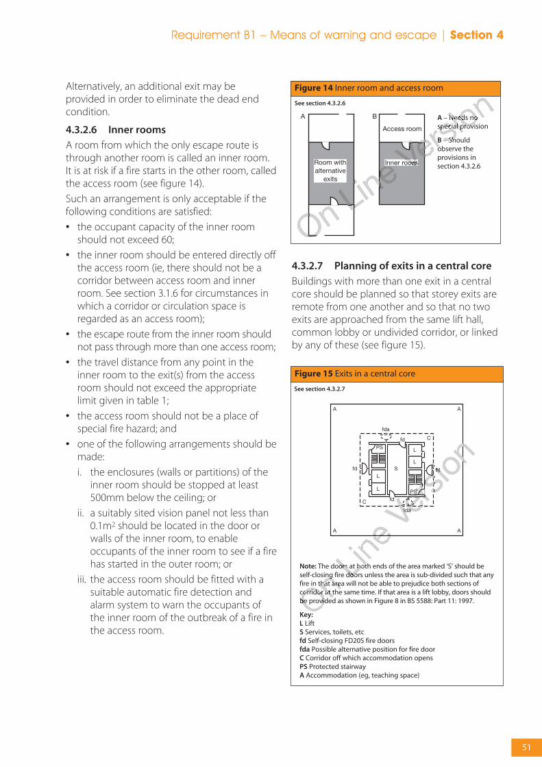
51
Requirement B1 – Means of warning and escape | Section 4
Alternatively, an additional exit may beprovided in order to eliminate the dead endcondition.
4.3.2.6 Inner rooms
A room from which the only escape route isthrough another room is called an inner room.It is at risk if a fire starts in the other room, calledthe access room (see figure 14).
Such an arrangement is only acceptable if thefollowing conditions are satisfied:
• the occupant capacity of the inner roomshould not exceed 60;
• the inner room should be entered directly offthe access room (ie, there should not be acorridor between access room and innerroom. See section 3.1.6 for circumstances inwhich a corridor or circulation space isregarded as an access room);
• the escape route from the inner room shouldnot pass through more than one access room;
• the travel distance from any point in theinner room to the exit(s) from the accessroom should not exceed the appropriatelimit given in table 1;
• the access room should not be a place ofspecial fire hazard; and
• one of the following arrangements should bemade:
i. the enclosures (walls or partitions) of theinner room should be stopped at least500mm below the ceiling; or
ii. a suitably sited vision panel not less than0.1m2 should be located in the door orwalls of the inner room, to enableoccupants of the inner room to see if a firehas started in the outer room; or
iii. the access room should be fitted with asuitable automatic fire detection andalarm system to warn the occupants ofthe inner room of the outbreak of a fire inthe access room.
4.3.2.7 Planning of exits in a central core
Buildings with more than one exit in a centralcore should be planned so that storey exits areremote from one another and so that no twoexits are approached from the same lift hall,common lobby or undivided corridor, or linkedby any of these (see figure 15).
Figure 14 Inner room and access room
A – Needs nospecial provision
B – Shouldobserve theprovisions insection 4.3.2.6
See section 4.3.2.6
Figure 15 Exits in a central core
See section 4.3.2.7
Note: The doors at both ends of the area marked ‘S’ should beself-closing fire doors unless the area is sub-divided such that anyfire in that area will not be able to prejudice both sections ofcorridor at the same time. If that area is a lift lobby, doors shouldbe provided as shown in Figure 8 in BS 5588: Part 11: 1997.
Key:L LiftS Services, toilets, etcfd Self-closing FD20S fire doorsfda Possible alternative position for fire doorC Corridor off which accommodation opensPS Protected stairwayA Accommodation (eg, teaching space)

52
Section 4 | Requirement B1 – Means of warning and escape
4.3.2.8 Open spatial planning
Where an open-plan space connects more thanone storey, rooms accessed from the spaceshould be treated as inner rooms (section4.3.2.6) with the space/balcony regarded as theaccess room. Any escape routes should not beprejudiced by openings in floors.
Escape routes should not be within 4.5m ofopenings unless:
• the direction of travel is away from theopening (eg, A-B in figure 16a); or
• there is an alternative escape route whichdoes not pass within 4.5m of the openconnection (eg, the rooms with alternativeexits in 16b).
In sprinklered schools, rooms which areaccessed by an open balcony less than 4.5mwide, and which do not have an alternativeescape route away from the balcony, shouldsatisfy the following conditions (see figure 16b):
• escape from any point on the balcony shouldbe available in at least two directions; and
• the travel distance along the balcony shouldnot exceed 18m.
Note: If the opening passes through acompartment floor (see section 6.3.2.1) then theguidance in BS 5588 Part 7 (1997) should befollowed for fire precaution in atria.
4.3.2.9 Access to storey exits
Any storey which has more than one escapestair should be planned so that it is notnecessary to pass through one stairway to reachanother. However it would be acceptable topass through one stairway’s protected lobby toreach another stair.
4.3.2.10 Separation of circulation routesfrom stairways
Unless the doors to a protected stairway andany associated exit passageway are fitted withan automatic release mechanism, the stairwayand any associated exit passageway should notform part of the primary circulation routebetween different parts of the building at thesame level. This is because the self-closing firedoors are more likely to be rendered ineffectiveas a result of their constant use, or becausesome occupants may regard them as animpediment. For example, the doors are likelyto be wedged open or have their closersremoved.
4.3.2.11 Height of escape routes
All escape routes should have a clear headroomof not less than 2m except in doorways.
Figure 16a Open connections and balconies
See section 4.3.2.8
The travel distance A-B should be in accordance with table 1.
Figure 16b Open connections and balconies
See section 4.3.2.8
A-B not to exceed 18m (if alternative exits do not exist)
C-D not to exceed 18m (max. length of a dead end)
The shorter of D-B or D-E not to exceed 18m
Rooms without alternative exits are treated as inner rooms (seesection 4.3.2.6)

53
Requirement B1 – Means of warning and escape | Section 4
4.3.2.12 Width of escape routes and exits
The width of escape routes and exits dependson the number of persons needing to use them.
BB98 (ref) states that: corridors leading to morethan one or two teaching spaces should have aclear width (see BS 8300:2001) of at least 1.8m;in new schools this minimum width should beat least 1.9m; if the corridor contains lockers thewidth should be 2.7m; and, smaller corridors (tonot more than one or two teaching spaces)should have a clear width of at least 1200mm –this conforms with Approved Document MAccess to and Use of buildings.
In dead ends, the minimum corridor width is1600mm unless a single room of less than 60people is served by a corridor of less than 4.5min length, in which case the width should notbe less than 1200mm.
For escape purposes, the minimum corridorwidth of 1200mm, as recommended by AD M,is sufficient if the corridor is not expected toserve as means of escape for more than 250people. If the number of people is greater thanthis, the minimum width should be increasedby an additional 50mm for each additional 10persons (or part of 10). However, larger corridorwidths should be used where possible, asrecommended by BB98.
The aggregate width of all the escape routesshould be not less than that required toaccommodate the maximum numbers ofpeople likely to use them.
Where the maximum number of people likely touse the escape route and exit is not known, theappropriate capacity should be calculated onthe basis of the occupant capacity (see table 2).
Guidance on the spacing of fixed seating forauditoria is given in BS 5588-6:1991.
The distance between a row of seats and the rowin front should be at least 305mm. Aisles between
blocks of seats should be 1050mm wide, and ablock of seats should be no more than 14 seatswide (ie, 7 seats to the nearest aisle).
4.3.2.13 Calculating exit capacity
If a storey or room has two or more storey exitsit has to be assumed that a fire might preventthe occupants from using one of them. Theremaining exit(s) need to be wide enough toallow all the occupants to leave quickly.Therefore when deciding on the total width ofexits needed according to table 4 below, thelargest exit should be discounted. This mayhave implications for the width of stairs,because they should be at least as wide as anystorey exit leading onto them. Although somestairs are not subject to discounting (see section4.4.5.2), the storey exits onto them will be.
Notes:
1. Refer to appendix E on methods of measurement.
2. In order to follow the guidance in BB 98 and AD M, thewidths given in the table may need to be increased(see section 4.3.2.12 for corridors, and table 5 for doors)
3. Widths less than 1050mm should not be interpolated.
4. May be reduced to 530mm for gangways betweenfixed storage racking.
5. 50mm for each additional 10 persons (or part of 10)does not apply to an opening serving less than 220persons.
AD M contains the following recommendationsfor the minimum widths of exit doors (see table 5).
Maximum number ofpersons
60
110
220
More than 220
Minimum width mm(1)(2)(3)
750(4)
850
1050
50mm for each additional10 persons or part of 10(5)
Table 4 Escape route width and exit capacity
Existing buildings (mm)
750
750
775
775
Table 5 Minimum effective clear widths of doors, recommended by AD M
Direction and width of approach
Straight on (without a turn or oblique approach)
At right angles to an access route at least 1500mm wide
At right angles to an access route at least 1200mm wide
External doors to buildings used by the general public
New buildings (mm)
800
800
825
1000
Note: where there are a large number of pupils withspecial educational needs (SEN), BB77 and the SSLD for
doors (ref) both recommend a clear open width of900mm.

54
Section 4 | Requirement B1 – Means of warning and escape
The total number of persons which two or moreavailable exits (after discounting) canaccommodate is found by adding themaximum number of persons that can beaccommodated by each exit width. Forexample, three exits each 850mm wide willaccommodate 3 x 110 = 330 persons (not the510 persons accommodated by a single exit2550mm wide).
Where a ground floor storey exit shares a finalexit with a stair via a ground floor lobby, thewidth of the final exit should be sufficient toenable a maximum evacuation flow rate equalto or greater than that from the storey exit andstair combined (see figure 17).
This can be calculated from the followingformula:
W = ((N/2.5) + (60S))/80
Where:
W = width of final exit, in metres
N = number of people served by ground floorstorey exit
S = stair width in metres
Note: Where the number of persons (N) enteringthe lobby from the ground floor is more than 60then the distance from the foot of the stair, orthe storey exit, to the final exit should be aminimum of two metres (see figure 17). Wherethis cannot be achieved then the width of the
final exit (W) should be no less than the width ofthe stair plus the width of the storey exit.
Worked example
A ground floor storey exit serving 250 personsshares a common final exit with a 1.2 m widestair.
Required final exit = ((250/2.5) + (1.2 x 60))/80width (metres) = 2.150 metres.
4.3.2.14 Protected corridors
Dead-end corridors should be avoided.However, where they are present in existingbuildings, every dead-end corridor (excludingrecesses and extensions not exceeding 2mdeep) should be a protected corridor. See alsosection 4.3.2.1 and 4.3.2.5.
4.3.2.15 Enclosure of corridors that are notprotected corridors
Where a corridor that is used as a means ofescape, but is not a protected corridor, isenclosed by partitions, those partitions providesome defence against the spread of smoke inthe early stages of a fire, even though they mayhave no fire resistance rating. To maintain thisdefence the partitions should be carried up tothe soffit of the structural floor above, or to asuspended ceiling and openings into roomsfrom the corridor should be fitted with doors,which need not be fire doors. Open planning,while offering no impediment to smoke spread,has the compensation that occupants canbecome aware of a fire quickly.
4.3.2.16 Sub-division of corridors
If a corridor provides access to alternativeescape routes, there is a risk that smoke willspread along it and make both routesimpassable before all occupants have escaped.
To avoid this, every corridor more than 12mlong which connects two or more storey exits,should be sub-divided by a self-closing firedoor(s) (and any necessary associated screens).The fire door(s) and any associated screen(s)should be positioned approximately mid-waybetween the two storey exits to effectivelysafeguard the route from smoke (having regardto the layout of the corridor and to any adjacentfire risks).
S
N
DD
W
Figure 17 Merging flows at final exit
Key:
D Minimum 2mwhere N is greaterthan 60
N Number of peopleserved by groundfloor storey exit
See section 4.3.2.13

55
Requirement B1 – Means of warning and escape | Section 4
Where a cavity exists above the enclosures toany such corridor, because the enclosures arenot carried to full storey height or (in the case of a top storey) to the underside of the roofcovering, the potential for smoke to bypass thesub-division should be restricted by fittingcavity barriers on the line of the enclosure(s) toand across the corridor.
Any door which could provide a path for smoke to bypass the sub-division should bemade self-closing (but need not necessarily be fire-resisting).
If a dead-end portion of a corridor providesaccess to a point from which alternative escaperoutes are available, there is a risk that smokefrom a fire could make both routes impassablebefore the occupants in the dead-end haveescaped.
To avoid this every dead-end corridorexceeding 4.5m in length should be separatedby self-closing fire doors (together with anynecessary associated screens) from any part ofthe corridor which:
a. provides two directions of escape (see figure19(a)); or
b. continues past one storey exit to another(see figure 19(b)).
Figure 18 Sub-division of corridors
See section 4.3.2.16
The sub-division should be carried full storey height andincludes sub-division of the corridor. A cavity barrier may beused in any ceiling void over the sub-division.
a. Section to show use of cavity barriers above the corridorenclosure.
Cavity barriersabove corridorenclosure andcross corridordoor.
Where the corridor is a protected escape route, cavity barriersmay also be required in any floor void beneath the corridorenclosure. See section 6.4.3.2
b. Plan showing sub-division of storey by fire-resistingconstruction, as required at a compartment wall.
Figure 19 Dead-end corridors
a. ‘T’ junction with main corridor
See section 4.3.2.16
b. Continuationpast stairway
Key:
Protected corridor fd Self-closing fire door

56
Section 4 | Requirement B1 – Means of warning and escape
4.3.2.17 External escape routes
Where an external escape route (other than astair) is beside an external wall of the building,that part of the external wall within 1800mm ofthe escape route should be of fire-resistingconstruction, up to a height of 1100mm abovethe paving level of the route. For guidance onexternal escape stairs see section 4.4.8.
4.3.2.18 Escape over flat roofs
If more than one escape route is available froma storey, or part of a building, one of thoseroutes may be by way of a flat roof, providedthat the route does not serve pupils or thepublic and:
• the roof should be part of the same buildingfrom which escape is being made;
• the route across the roof should lead to astorey exit or external escape route;
• the part of the roof forming the escape routeand its supporting structure, together withany opening within 3m of the escape route,should be fire-resisting (see appendix A tableA1); and
• the route should be adequately defined andguarded by walls and/or protective barrierswhich meet the provisions in ApprovedDocument K, Protection from falling, collisionand impact.
4.4 Design for vertical escape
4.4.1 Introduction
An important aspect of means of escape inmulti-storey buildings is the availability of asufficient number of adequately sized andprotected escape stairs. This section deals withescape stairs and includes measures necessaryto protect them in all types of building.
The limitation of distances of horizontal travelfor means of escape purposes means that mostpeople should be able independently to reachthe safety of a protected escape route or finalexit. However, some people, for example thosewho use wheelchairs, may not be able to usestairways without assistance. For themevacuation involving the use of refuges onescape routes and either assistance down (or
up) stairways, or the use of suitable lifts, will benecessary.
This section should be read in conjunction withthe general provisions in section 4.5.
4.4.1.1 Exclusions on escape routes
Note that spiral stairs and fixed ladders areprecluded from use in schools as part of anescape route for pupils – see section 4.5.4.3 (ADK Stairs Ramps and Guards). Similarly, singlesteps, apart from in doorways, should beavoided on escape routes. Lifts (except fire-fighting lifts and for a suitably designed andinstalled evacuation lift that may be used for theevacuation of disabled people in a fire); portableladders and throw-out ladders; andmanipulative apparatus and appliances, eg, folddown ladders and chutes are not deemed to beappropriate.
4.4.2 Number of escape stairs
The number of escape stairs needed in abuilding (or part of a building) will bedetermined by:
• the constraints imposed in section 4.3 on thedesign of horizontal escape routes;
• whether a single stair is acceptable(seesection 4.4.2.1); and
• provision of adequate width for escape (seesection 4.4.4) while allowing for thepossibility that a stair may have to bediscounted because of fire or smoke (seesection 4.4.5.2).
In larger buildings, provisions for access for theFire and Rescue Service may apply, in whichcase, some escape stairs may also need to serveas fire-fighting stairs. The number of escapestairs may therefore be affected by provisionsmade in section 8.4.3.
4.4.2.1 Single escape stairs
Ideally, single stairways should be avoided innew buildings. This is consistent with theavoidance of dead ends in new buildings.
The situations where a building (or part of abuilding) may be served by a single escape stairare:
a. from a basement which is allowed to have asingle escape route in accordance withsection 4.3.2.1 and table 1; and
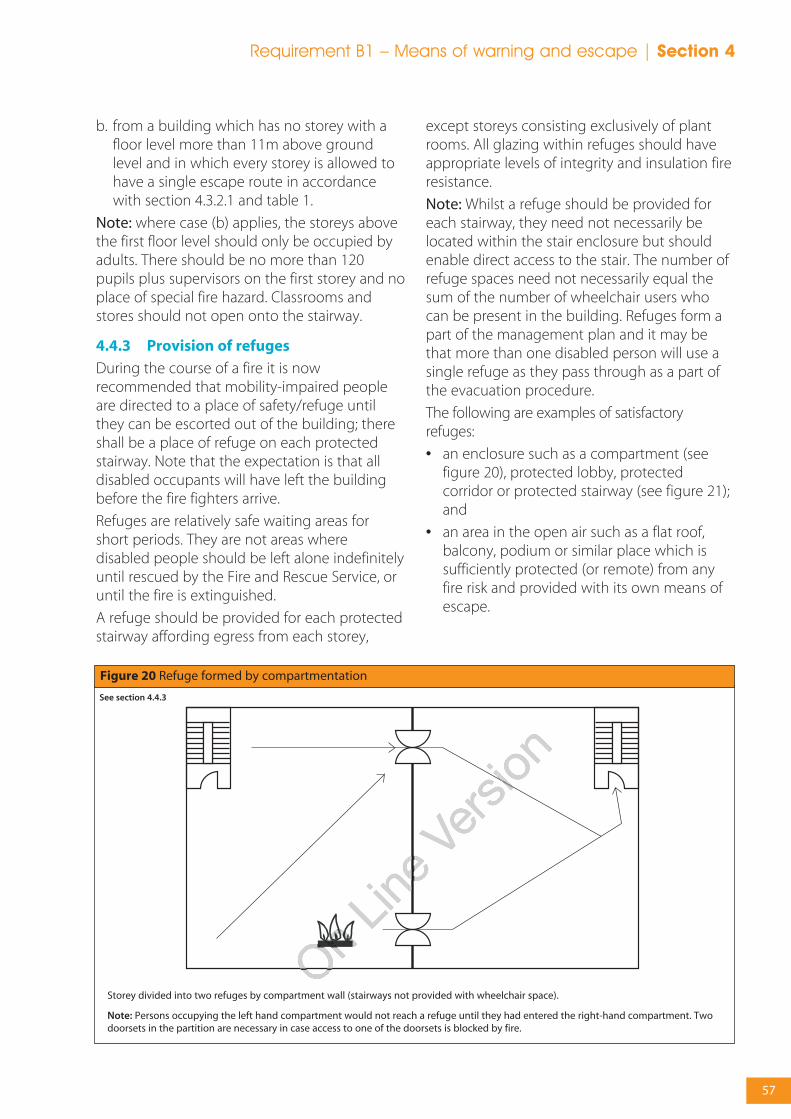
57
Requirement B1 – Means of warning and escape | Section 4
b. from a building which has no storey with afloor level more than 11m above groundlevel and in which every storey is allowed tohave a single escape route in accordancewith section 4.3.2.1 and table 1.
Note: where case (b) applies, the storeys abovethe first floor level should only be occupied byadults. There should be no more than 120pupils plus supervisors on the first storey and noplace of special fire hazard. Classrooms andstores should not open onto the stairway.
4.4.3 Provision of refuges
During the course of a fire it is nowrecommended that mobility-impaired peopleare directed to a place of safety/refuge untilthey can be escorted out of the building; thereshall be a place of refuge on each protectedstairway. Note that the expectation is that alldisabled occupants will have left the buildingbefore the fire fighters arrive.
Refuges are relatively safe waiting areas forshort periods. They are not areas wheredisabled people should be left alone indefinitelyuntil rescued by the Fire and Rescue Service, oruntil the fire is extinguished.
A refuge should be provided for each protectedstairway affording egress from each storey,
except storeys consisting exclusively of plantrooms. All glazing within refuges should haveappropriate levels of integrity and insulation fireresistance.
Note: Whilst a refuge should be provided foreach stairway, they need not necessarily belocated within the stair enclosure but shouldenable direct access to the stair. The number ofrefuge spaces need not necessarily equal thesum of the number of wheelchair users whocan be present in the building. Refuges form apart of the management plan and it may bethat more than one disabled person will use asingle refuge as they pass through as a part ofthe evacuation procedure.
The following are examples of satisfactoryrefuges:
• an enclosure such as a compartment (seefigure 20), protected lobby, protectedcorridor or protected stairway (see figure 21);and
• an area in the open air such as a flat roof,balcony, podium or similar place which issufficiently protected (or remote) from anyfire risk and provided with its own means ofescape.
Figure 20 Refuge formed by compartmentation
See section 4.4.3
Storey divided into two refuges by compartment wall (stairways not provided with wheelchair space).
Note: Persons occupying the left hand compartment would not reach a refuge until they had entered the right-hand compartment. Twodoorsets in the partition are necessary in case access to one of the doorsets is blocked by fire.

58
Section 4 | Requirement B1 – Means of warning and escape
Each refuge should provide an area accessibleto a wheelchair of at least 900mm x 1400mm inwhich a wheelchair user can await assistance.Where a refuge is a protected stairway orprotected lobby or protected corridor, thewheelchair space should not reduce the widthof the escape route. Where the wheelchairspace is within a protected stairway, access tothe wheelchair space should not obstruct theflow of persons escaping.
Refuges and evacuation lifts should be clearlyidentified by appropriate fire safety signs. Wherea refuge is in a lobby or stairway the sign shouldbe accompanied by a blue mandatory signworded ‘Refuge – keep clear’.
4.4.3.1 Communication
To facilitate the effective evacuation of peoplefrom refuges an emergency voicecommunication (EVC) system should beprovided. It is essential that the occupants ofeach refuge are able to alert other people thatthey are in need of assistance and for them tobe reassured that this assistance will beforthcoming.
The EVC system should comply with BS 5839-9:2003 and consist of Type B outstations whichcommunicate with a master station located inthe building control room (where one exists) oradjacent to the fire alarm panel.
In some buildings it may be more appropriateto use an alternative approach such as the useof wireless technology.
4.4.4 Width of escape stairs
The width of escape stairs should:
• be at least 1100mm;
• be not less than the width(s) required for anyexit(s) affording access to them;
• conform with the minimum widths given intable 6; and
• not reduce in width at any point on the wayto a final exit.
In order to follow the guidance in AD M, BB77and the SSLD for stairs (ref), the minimumwidths may need to be increased. For example,the SSLD for stairs sets a minimum width of1600mm. Note however that the SSLD onlyapplies to new secondary schools.
If the resultant width of the stair is more than1800mm, then for reasons of safety in normaluse, the guidance in Approved Document KProtection from falling, collision and impact, isthat the stair should have a central handrail. Insuch a case the stair width on each side of thecentral handrail needs to be consideredseparately for the purpose of assessing staircapacity. Coupled with the requirement that nostair should be less than 1100mm wide, thismeans there will be no stair between 1800mmand 2200mm wide.
A second handrail at low height should beprovided for younger children.
Where an exit route from a stair also forms theescape from the ground and/or basementstoreys, the width may need to be increasedaccordingly (see section 4.3.2.13).
4.4.5 Calculation of minimum stair width
The capacity of stairs and exits will need to becalculated based upon the premise that at leastone of the alternatives will become smoke-logged and so everyone will have to use theremaining exits.
4.4.5.1 General
Every escape stair should be wide enough toaccommodate the number of persons needing
Figure 21 Refuge formed in a protected stairway
Provision where access to the wheelchair space is counter to theaccess flow within the stairway.
See section 4.4.3
Key:
Wheelchair space Occupied by escape flow

59
Requirement B1 – Means of warning and escape | Section 4
to use it in an emergency. This width willdepend on the number of stairs provided.
As with the design of horizontal escape routes,where the maximum number of peopleneeding to use the escape stairs is not known,the occupant capacity should be calculated onthe basis of the appropriate floor space factors.Guidance for this is set out in table 2.
4.4.5.2 Discounting of stairs
Where two or more stairs are provided it shouldbe assumed that one of them might not beavailable due to fire. It is therefore necessary todiscount each stair in turn in order to ensurethat the capacity of the remaining stair(s) isadequate for the number of persons needing toescape. The stair discounting rule applies to abuilding fitted with a sprinkler system.
Two exceptions to the above discounting rulesare if the escape stairs:
• are protected by a smoke control systemdesigned in accordance with BS EN 12101-6:2005; and
• are approached on each storey through aprotected lobby (a protected lobby need notbe provided on the topmost storey for theexception still to apply).
In such cases the likelihood of a stair not beingavailable is significantly reduced and it is notnecessary to discount a stair. However, a storeyexit still needs to be discounted, see section4.3.2.13.
4.4.5.3 Stair Capacity
The escape stairs (in conjunction with the restof the means of escape) should have thecapacity to allow all floors to be evacuatedsimultaneously. In calculating the width of thestairs account is taken of the number of peopletemporarily housed in the stairways during theevacuation.
The minimum width of a stair is 1100mm,serving up to 220 people. When designing forgreater numbers of people, the capacity of stairsof widths from 1100 to 1800mm is given intable 6. Note that these stair widths assume asimultaneous evacuation of the entire building.Phased evacuation is not consideredappropriate for school buildings.
As an alternative to using table 6, the capacityof stairs 1100mm or wider (for simultaneousevacuation) can be derived from the formula:
p = 200w + 50(w - 0.3)(n - 1)
or
where:
(P) is the number of people that can be served;(w) is the width of the stair, in metres; and (n) is the number of storeys served.
Note 1: Separate calculations should be madefor stairs/flights serving basement storeys andthose serving upper storeys.
Note 2: The population ‘P’ should be divided bythe number of available stairs.
P + 15n - 15w =
150 + 50n
No offloorsserved
1
2
3
4
5
6
Maximum number of persons served by a stair of width
1300mm
260
310
360
410
460
510
1100mm
220
260
300
340
380
420
1200mm
240
285
330
375
420
465
1400mm
280
335
390
445
500
555
1500mm
300
360
420
480
540
600
1600mm
320
385
450
515
580
645
1700mm
340
410
480
550
620
690
1800mm
360
435
510
585
600
735
Table 6 Capacity of a stair for basements and for simultaneous evacuation of the building
* Should it be necessary to go above six floors the designer is recommended to use guidance in AD B.
60
Section 4 | Requirement B1 – Means of warning and escape
Note 3: The formula is particularly useful whendetermining the width of stairs serving abuilding (or part of a building) where theoccupants are not distributed evenly – eitherwithin a storey or between storeys.
Note 4: In the formula, the first part (200w)represents the number of persons estimated tohave left the stair after 2.5 minutes ofevacuation. The second part (50 (w-0.3) (n-1))represents the number of persons estimated tobe accommodated on the stair after this time.
Example
Consider a school with 4 storeys, 4 stairs,containing 1680 pupils and staff. The number offloors served is 3 (the fourth storey is theground floor). Assuming an even distribution ofpupils and staff over the four storeys, there willbe 420 people per floor.
If it is assumed that one stair is unavailable dueto smoke-logging, the 1260 people not on theground floor will have to use the threeremaining stairs, ie, 420 people per stair.Substituting P = 420 and n = 3 into the formulafor w gives
If all the stairs have smoke control or lobbyprotection, it is reasonable to assume that theywill not become smoke-logged in the event of afire. However, a storey exit should still bediscounted since the location of the fire on astorey may make an exit inaccessible. Assumingthe fire is not on the ground floor, the numberof people using the stair will be:
• 420/3 = 140 people per stair from the firefloor; and
• 420/4 = 105 people per stair from each of theother two floors.
ie, a total of 350 people per stair.
Using the formula for w, this gives:
The use of smoke control or lobby protectionmeans that narrower stairs can be used.
4.4.6 Protection of escape stairs
4.4.6.1 General
Escape stairs need to have a satisfactorystandard of fire protection if they are to fulfiltheir role as areas of relative safety during a fireevacuation. The guidance in section 4.4.6.2should be followed to achieve this.
One of the benefits of protecting stairways fromthe effects of fire is to allow travel distance tobe measured from the furthest point on therelevant floor to the nearest storey exit ratherthan the final exit of the building.
4.4.6.2 Enclosure of escape stairs
Every internal escape stair should be aprotected stairway (ie, it should be within a fire-resisting enclosure).
However an unprotected stair (eg, anaccommodation stair) may form part of aninternal route to a storey exit or final exit,provided that the distance of travel and thenumber of people involved are very limited.
4.4.6.3 Access lobbies and corridors
There are situations where an escape stairneeds the added protection of a protectedlobby or protected corridor. These are:
• where the stair is the only one serving abuilding (or part of a building) which hasmore than one storey above or below theground storey;
• where the stair is a fire-fighting stair; or
• where the option in section 4.4.5.2 (secondbullet of second paragraph) has been usedso as not to discount one stairway whencalculating stair widths.
In these cases protected lobbies or protectedcorridors are needed at all levels, except the topstorey and at all basement levels. Alternatively asmoke control system may be used, unless thestair is a fire-fighting stair, to ensure the stairwayremains smoke free.
A protected lobby should also be providedbetween an escape stairway and a place ofspecial fire hazard. In this case, the lobby shouldhave not less than 0.4m2 of permanentventilation.
350 + 15 x 3 - 15 380w =
150 + 50 x 3 =
300 = 1.267
420 + 15 x 3 - 15 450w =
150 + 50 x 3 =
300 = 1.5

61
Requirement B1 – Means of warning and escape | Section 4
4.4.6.4 Exits from protected stairways
Every protected stairway should dischargedirectly to a final exit; or by way of a protectedexit passageway to a final exit. Any suchprotected exit passageway should have thesame standard of fire resistance and lobbyprotection as the stairway it serves.
The exit from a protected stairway should meetthe provisions in section 4.5.5.4.
4.4.6.5 Separation of adjoining stairways
Where two protected stairways are adjacent,they and any protected exit passagewayslinking them to final exits, should be separatedby an imperforate barrier.
4.4.6.6 Use of space within protectedstairways
A protected stairway needs to be free ofpotential sources of fire. Consequently, facilitiesthat may be incorporated in a protectedstairway are limited to the following:
a. sanitary accommodation or washrooms, solong as the accommodation is not used as acloakroom. A gas water heater or sanitarytowel incinerator may be installed in theaccommodation but not any other gasappliance;
b. a lift well may be included in a protectedstairway, if it is not a fire-fighting stair (see8.4.1);
c. a reception desk or enquiry office area atground or access level, if it is not in the onlystair serving the building or part of thebuilding. The reception or enquiry office areashould not be more than 10m2 in area; and/or
d. cupboards enclosed with fire-resistingconstruction, if they are not in the only stairserving the building or part of the building.
4.4.6.7 External walls of protectedstairways
With some configurations of external wall, a firein one part of a building could subject theexternal wall of a protected stairway to heat (forexample, where the two are adjacent at aninternal angle in the facade as shown in figure22). If the external wall of the protected stairwayhas little fire resistance, there is a risk that thiscould prevent the safe use of the stair.
Therefore, if:
a. a protected stairway projects beyond, or isrecessed from, or is in an internal angle of,the adjoining external wall of the building;then
b. the distance between any unprotected areain the external enclosures to the building andany unprotected area in the enclosure to thestairway should be at least 1800mm (seefigure 22).
Figure 22 External protection to protected stairways
Configurations of stairs and external wall
See section 4.4.6.7
Key:
Fire-resisting construction
Non fire-resisting construction
Configuration A
Configuration B

62
Section 4 | Requirement B1 – Means of warning and escape
4.4.7 Basement stairs
Because of their situation, basement stairwaysare more likely to be filled with smoke and heatthan stairs in ground and upper storeys.
Special measures are therefore needed in orderto prevent a basement fire endangering upperstoreys.
If an escape stair forms part of the only escaperoute from an upper storey of a building (or partof a building) it should not be continued down
to serve any basement storey. The basementshould be served by a separate stair.
If there is more than one escape stair from anupper storey of a building (or part of a building),only one of the stairs serving the upper storeysof the building (or part) need be terminated atground level. Other stairs may connect with thebasement storey(s) if there is a protected lobby,or a protected corridor between the stair(s) andaccommodation at each basement level.
Figure 23 Fire resistance to areas adjacent to external stairs
See section 4.4.8
Example A
Example B
Section A-A Section B-B
Plan
63
Requirement B1 – Means of warning and escape | Section 4
4.4.8 External escape stairs
If more than one escape route is available from astorey (or part of a building), some of the escaperoutes from that storey or part of the buildingmay be by way of an external escape stair,provided that:
• there is at least one internal escape stair fromevery part of each storey (excluding plantareas); and
• the route is not intended for use by pupils ormembers of the public; or
• the route does not extend above the first floor.
Where external stairs are acceptable as formingpart of an escape route, they should meet thefollowing provisions:
• all doors giving access to the stair should be fire-resisting and self-closing, except that a fire-resisting door is not required at the head of anystair leading downwards where there is onlyone exit from the building onto the top landing;
• any part of the external envelope of thebuilding within 1800mm of (and 9m verticallybelow), the flights and landings of an externalescape stair should be of fire-resistingconstruction, except that the 1800mmdimension may be reduced to 1100mm abovethe top level of the stair if it is not a stair up froma basement to ground level (see figure 23);
• there is protection by fire-resistingconstruction for any part of the building(including any doors) within 1800mm of theescape route from the stair to a place of safety,unless there is a choice of routes from the footof the stair that would enable the peopleescaping to avoid exposure to the effects ofthe fire in the adjoining building;
• any stair more than 6m in vertical extent isprotected from the effects of adverse weatherconditions. (This should not be taken to implya full enclosure. Much will depend on thelocation of the stair and the degree ofprotection given to the stair by the buildingitself); and
• glazing in areas of fire-resisting constructionmentioned above should also be fire-resistingand normally integrity performance orinsulation performance where a riskassessment indicates that the potential firehazard requires protection against heat in thepost flashover phase.
4.5 General provisions for means ofescape
4.5.1 Introduction
This section gives guidance on the constructionand protection of escape routes generally,service installations and other matters associatedwith the design of escape routes.
It should therefore be read in conjunction withsections 4.3 and 4.4.
4.5.2 Protection of escape routes
If a fire starts, then however it spreads within thebuilding it must not compromise the use ofdedicated, protected escape routes. Such routesare protected by elements of construction thatare able to satisfy the appropriate criteria of thefire resistance test, see appendix A.
4.5.2.1 Fire resistance of enclosures
Other elements of the structure may be requiredto provide fire resistance for the purpose of:
• reducing the area of the building that is at risk,in line with regulatory recommendations;
• protecting against disproportionate damageto the facility in the event of a fire;
• containing areas of high risk; and
• protecting areas that are critical to the runningof the school, or have a high intrinsic value.
Details of fire resistance test criteria andstandards of performance, are set out inappendix A. Generally, a 30-minute standard issufficient for the protection of means of escape.The exceptions to this are when greater fireresistance is required by the guidance onRequirements B3 or B5, or some other specificinstance to meet Requirement B1 (see section 4.3).
All walls, partitions and other enclosures thatneed to be fire-resisting to meet the provisions inthis document (including roofs that form part ofa means of escape), should have the appropriateperformance given in tables A1 and A2 ofappendix A.
Glazed elements protecting a means of escapeshould meet limitations defined for the use ofintegrity glass (see section 4.5.2.3).
4.5.2.2 Fire resistance of doors
Details of fire resistance test criteria and standardsof performance, are set out in appendix C.

64
Section 4 | Requirement B1 – Means of warning and escape
All doors that need to be fire-resisting to meetthe provisions in this document should have theappropriate performance given in table C1 ofappendix C.
Doors should also meet limitations defined forintegrity glass (see section 4.5.2.3).
4.5.2.3 Fire resistance of glazed elements
Where glazed elements in fire-resistingenclosures and doors are only able to satisfy therelevant performance in terms of integrity, theuse of glass is limited. These limitations dependon whether the enclosure forms part of aprotected shaft (see section 6.3) and theprovisions set out in appendix A, table A4.
Where the relevant performance can be met interms of both integrity and insulation, there is norestriction in this document on the use oramount of glass.
Attention is also drawn to the guidance on thesafety of glazing in Approved Document N,Glazing – safety in relation to impact, opening andcleaning.
4.5.3 Doors on escape routesThe time taken to negotiate a closed door can becritical in escaping. Doors on escape routes (bothwithin and from the building) should thereforebe readily openable, if undue delay is to beavoided. Accordingly the provisions in section4.5.3.1 – 4.5.3.5 should be met.
4.5.3.1 Door fastenings
In general, doors on escape routes (whether ornot the doors are fire doors), should either not befitted with lock, latch or bolt fastenings, or theyshould only be fitted with simple fastenings thatcan be readily operated from the sideapproached by people making an escape. Theoperation of these fastenings should be readilyapparent; without the use of a key and withouthaving to manipulate more than one mechanism.This is not intended to prevent doors being fittedwith hardware to allow them to be locked whenthe rooms are empty.
Where a door on an escape route has to besecured against entry when the building or partof the building is occupied, it should only befitted with a lock or fastening which is readilyoperated, without a key, from the sideapproached by people making their escape.Similarly, where a secure door is operated by acode, combination, swipe or proximity card,
biometric data or similar means, it should also becapable of being overridden from the sideapproached by people making their escape.
Electrically powered locks should return to theunlocked position:
• on operation of the fire alarm system;
• on loss of power or system error; and
• on activation of a manual door release unit(Type A) to BS EN 54-11:2001 positioned at thedoor on the side approached by peoplemaking their escape. Where the door providesescape in either direction, a unit should beinstalled on both sides of the door.
Doors on escape routes from rooms with anoccupant capacity of more than 60 should eithernot be fitted with lock, latch or bolt fastenings, orbe fitted with panic fastenings in accordancewith BS EN 1125:1997.
It may also be appropriate to accept on somefinal exit doors locks for security that are usedonly when the building is empty. In these casesthe emphasis for the safe use of these locks mustbe placed on management procedures.
Guidance about door closing and ‘hold-open’devices for fire doors is given in appendix C.
4.5.3.2 Direction of opening
The door of any doorway or exit should, ifreasonably practicable, be hung to open in the direction of escape and should always do so if the number of persons that might beexpected to use the door at the time of a fire is more than 60.
Note: Where there is a very high fire risk withpotential for rapid fire growth, doors shouldopen in the direction of escape even where thenumber of persons does not exceed 60.
4.5.3.3 Amount of opening and effect onassociated escape routes
All doors on escape routes should be hung toopen not less than 90 degrees with a swing thatis clear of any change of floor level, other than athreshold or single step on the line of thedoorway (see section 4.5.4.2) and which does notreduce the effective width of any escape routeacross a landing.
A door that opens towards a corridor or astairway should be sufficiently recessed toprevent its swing from encroaching on theeffective width of the stairway or corridor.
65
Requirement B1 – Means of warning and escape | Section 4
4.5.3.4 Vision panels in doors
Vision panels are needed where doors onescape routes sub-divide corridors, or whereany doors are hung to swing both ways. Notealso the provision in Approved Document M,Access to and Use of buildings, concerning visionpanels in doors across accessible corridors andpassageways and the provisions for the safety ofglazing in Approved Document N, Glazing –safety in relation to impact, opening and cleaning.
Vision panels in insulating doors should be ofinsulating fire-resisting glass, in which case thearea of use of the insulating glass does notneed to be limited. If uninsulating fire-resistantglazing is used, the vision panels should be lessthan 10% of the door area, and not be less than500mm above the floor.
4.5.3.5 Revolving and automatic doors
Revolving doors, automatic doors and turnstilescan obstruct the passage of persons escaping.Accordingly, they should not be placed acrossescape routes unless:
• they are to the required width and areautomatic doors and either they:
i. are arranged to fail safely to outwardopening from any position of opening; or
ii. are provided with a monitored failsafesystem for opening the doors if the mainssupply fails; or
iii. they fail safely to the open position in theevent of power failure;
• non-automatic swing doors of the requiredwidth are provided immediately adjacent tothe revolving or automatic door or turnstile.
4.5.4 Stairs
4.5.4.1 Construction of escape stairs
The flights and landings of every escape stairshould be constructed of materials of limitedcombustibility in the following situations:
a. if it is the only stair serving the building, orpart of the building;
b. if it is within a basement storey;
c. if it is external (see section 4.4.8); or
d. if it is a fire-fighting stair (see section 8.4).
Note: In satisfying the above conditions,combustible materials may be added to thehorizontal surface of these stairs (except in thecase of fire-fighting stairs).
There is further guidance on the construction offire-fighting stairs in section 8.4. Dimensionalconstraints on the design of stairs generally, tomeet requirements for safety in use, are given inApproved Document K, Protection from falling,collision and impact.
The preferred rise for each step should be notmore than 150mm, and the tread between250mm and 280mm (not less than the lowervalue), for steps in general, and that thereshould be between 3 and 16 treads per flight.The length of any landing on a staircase shouldbe at least the width of the stair, and thereshould be a change of direction at least everytwo flights.
4.5.4.2 Single steps
Single steps may cause falls and should only beused on escape routes where they areprominently marked. A single step on the line of adoorway is acceptable, subject to section 4.5.5.4.
The rise should be not more than 150mm, andthe tread not less than 300mm, for stepsproviding for small changes in level. Thereshould be a level stretch of corridor extendingfor 1.5m either side of any such steps.
4.5.4.3 Helical stairs, spiral stairs and fixedladders
Helical stairs, spiral stairs and fixed ladders mayform part of an escape route, provided they arenot intended to serve pupils or members of thepublic, subject to the following restrictions:
a. helical and spiral stairs should be designed inaccordance with BS 5395-2:1984; and
b. fixed ladders should only be intended for usein circumstances where it is not practical toprovide a conventional stair, for example, asaccess to plant rooms that are not normallyoccupied.
Guidance on the design of helical and spiralstairs and fixed ladders, from the aspect ofsafety in use, is given in Approved Document K,Protection from falling, collision and impact.
4.5.5 General
4.5.5.1 Headroom in escape routes
All escape routes should have a clear headroomof not less than 2m and there should be noprojection below this height (except for doorframes).
66
Section 4 | Requirement B1 – Means of warning and escape
4.5.5.2 Floors of escape routes
The floorings of all escape routes (including thetreads of steps and surfaces of ramps andlandings) should be chosen to minimise theirslipperiness when wet.
4.5.5.3 Ramps and sloping floors
Where a ramp forms part of an escape route itshould meet the provisions in ApprovedDocument M, Access to and Use of buildings. Anysloping floor or tier should be constructed with apitch of not more than 35º to the horizontal.
Inclines and ramps may be preferable to stairs,particularly where the change in level is slight, orwhere wheelchair access is a requirement. Thegradient of the incline or ramp should notexceed 1:12. AD M has further details.
Further guidance on the design of ramps andassociated landings and on aisles and gangwaysin places where there is fixed seating, from theaspect of safety in use, is given in AD K and ADM. The design of means of escape in places withfixed seating is dealt with in section 4.3.2.12 byreference to BS 5588-6:1991.
4.5.5.4 Final exits
Final exits need to be dimensioned and sited tofacilitate the evacuation of persons out of andaway from the building. Accordingly, they shouldbe not less in width than the minimum widthrequired for the escape route(s) they serve andshould also meet the conditions below.
Final exits should be sited to ensure rapiddispersal of persons from the vicinity of thebuilding so that they are no longer in dangerfrom fire and smoke. Direct access to a street,passageway, walkway or open space should beavailable. The route clear of the building shouldbe well defined and, if necessary, have suitableguarding.
The designers shall ensure adequate provision ismade for the safe assembly of the schooloccupants, for example:
• Final exits to an enclosed courtyard are notsuitable.
• Assembly points should not get in the way ofaccess for the Fire and Rescue Service.
• Assembly points should not be at risk frombreaking glass falling from windows of thebuilding façade.
Escape routes from facilities such as indoorswimming pools and games areas will need toallow for possible egress in cold weather as wellas day and night-time conditions.
Final exits should not present an obstacle towheelchair users and other people withdisabilities. Where a final exit is accessed withoutthe need to first traverse steps then a levelthreshold and, where necessary, a ramp shouldbe provided.
Final exits need to be apparent to persons whomay need to use them. This is particularlyimportant where the exit opens off a stair thatcontinues down, or up, beyond the level of thefinal exit.
Final exits should be sited so that they are clearof any risk from fire or smoke in a basement(such as the outlets to basement smoke vents,see section 8.5), or from openings to transformerchambers, refuse chambers, boiler rooms andsimilar risks.
4.5.5.5 Lighting of escape routesAll escape routes should have adequate artificiallighting. Routes and areas apart from theexceptions listed below should also have escapelighting which illuminates the route if the mainsupply fails. The exceptions are:
a. accommodation open on one side to viewsport or entertainment during normal daylighthours;
b. parts of school buildings with natural light andused only during normal school hours; and
c. toilet accommodation with a window andwith a floor area not more than 8m2.
Lighting to escape stairs should be on a separatecircuit from that supplying any other part of theescape route.
Standards for the installation of a system ofescape lighting are given in BS 5266-1:2005.
4.5.5.6 Exit signsEvery escape route (other than those in ordinaryuse) should be distinctively and conspicuouslymarked by emergency exit sign(s) of adequatesize complying with the Health and Safety (Safetysigns and signals) Regulations, 1996. In general,signs containing symbols or pictograms whichconform to BS 5499-1:2002, satisfy theseregulations. In some buildings additional signsmay be needed to meet requirements underother legislation.

67
Requirement B1 – Means of warning and escape | Section 4
Suitable signs should also be provided forrefuges (see section 4.4.3).
Note: Advice on fire safety signs, includingemergency escape signs, is given in an HSEpublication: Safety Signs and Signals: Guidance onRegulations. Further guidance is given in RROGuide Part 2, section 6 on safety signs andnotices.
4.5.5.7 Protected power circuits
Where it is critical for electrical circuits to be ableto continue to function during a fire, protectedcircuits are needed. The potential for damage tocables forming protected circuits should belimited by the use of sufficiently robust cables,careful selection of cable routes and/or by theprovision of physical protection in areas wherecables may be susceptible to damage. Methodsof cable support should generally be non-combustible and such that circuit integrity willnot be reduced below that afforded by the cable.
A protected circuit for operation of equipment inthe event of fire should consist of cable meetingat least the requirements for PH 30 classificationwhen tested in accordance with BS EN50200:2006 (incorporating appendix E of thatstandard), or an equivalent standard. It shouldfollow a route selected to pass only throughparts of the building in which the fire risk isnegligible and should be separate from anycircuit provided for another purpose.
In large or complex buildings there may be fireprotection systems, eg, sprinkler systems, thatneed to operate for an extended period during afire. Further guidance on the selection of cablesfor such systems is given in BS 5839-1, BS 5266-1and BS 7346-6.
4.5.6 Lifts
4.5.6.1 Evacuation lifts
In general it is not appropriate to use lifts whenthere is a fire in the building because there isalways the danger of people being trapped in alift that has become immobilised as a result ofthe fire. However, in some circumstances a liftmay be provided as part of a management planfor evacuating people. In such cases the liftinstallation may need to be appropriately sitedand protected and may need to contain anumber of safety features that are intended to
ensure that the lift remains usable for evacuationpurposes during the fire. Guidance on the designand use of evacuation lifts is given in BS 5588-8:1999.
As schools have become more inclusive, theneed for lifts to assist those pupils with limitedmobility is increasingly widespread. It may bebeneficial to design all lifts to be used asevacuation lifts, which will assist the safe escapeof anyone with a mobility problem. AD M givesdetails of minimum lift dimensions, ie, 1100mmwide and 1400mm deep.
4.5.6.2 Fire protection of lift installations
Because lifts connect floors, there is thepossibility that they may prejudice escape routes.To safeguard against this, the conditions belowshould be met.
Lifts, such as wall-climber or feature lifts whichrise within a large volume, such as a mall oratrium, and do not have a conventional well, maybe at risk if they run through a smoke reservoir. Inwhich case, care is needed to maintain theintegrity of the smoke reservoir and protect theoccupants of the lift.
Lift wells should be either:
a. contained within the enclosures of aprotected stairway; or
b. enclosed throughout their height with fire-resisting construction if they are sited so as toprejudice the means of escape.
A lift well connecting different compartmentsshould form a protected shaft (see section 6.3).
In basements the lift should be approached onlyby a protected lobby (or protected corridor),unless it is within the enclosure of a protectedstairway.
A lift shaft should not be continued down toserve any basement storey if it is:
a. in a building (or part of a building) served byonly one escape stair and smoke from abasement fire would be able to prejudice theescape routes in the upper storeys; or
b. within the enclosure to an escape stair whichis terminated at ground level.
If the lift well is within a protected stairway whichis the only stairway serving the building (or partof the building), then lift motors should not be

68
Section 4 | Requirement B1 – Means of warning and escape
located in the stairway (to avoid smoke spreadfrom a fire in the lift machinery). However, liftmachine rooms, if required, can be sited overthe lift well.
4.5.7 Mechanical ventilation and air-conditioning systems
Any system of mechanical ventilation should bedesigned to ensure that, in a fire, the ductworkdoes not assist in transferring fire and smokethrough the building and put at risk theprotected means of escape from theaccommodation areas. Any exhaust pointsshould be sited so as not to further jeopardizethe building, ie, away from final exits,combustible building cladding or roofingmaterials and openings into the building.
Ventilation ducts supplying or extracting airdirectly to or from a protected escape route,should not also serve other areas. A separateventilation system should be provided for eachprotected stairway. Where the ductwork systemserves more than one part of a sub-divided (seesection 4.3.2.16) escape route, a fire dampershould be provided where ductwork enterseach section of the escape route operated by asmoke detector or suitable fire detection system(see also section 6.5). The fire dampers shouldclose when smoke is detected.
Ducts passing through the enclosure of aprotected escape route should be fire-resisting,ie, the ductwork should be constructed inaccordance with Method 2 or Method 3 (seesection 6.5).
Note: Fire dampers activated only by fusiblelinks are not suitable for protecting escaperoutes. However an ES classified fire and smokedamper which is activated by a suitable firedetection system may be used (see section6.5.3.1).
In the case of a system which recirculates air,smoke detectors should be fitted in the extractductwork before the point of separation of therecirculated air and the air to be discharged tothe open air and before any filters or other aircleaning equipment. Such detector(s) should:
a. cause the system to immediately shut down;or
b. switch the ventilation system fromrecirculating mode to extraction to open air,so as to divert any smoke to the outside ofthe building.
Mechanical ventilation, unless specificallydesigned for smoke extraction, should be shutdown as soon as smoke is detected in the duct,or upon operation of the fire alarm.
Non-domestic kitchens and plant rooms shouldhave separate and independent extractionsystems and the extracted air should not berecirculated.
Guidance on the use of mechanical ventilationis given in BS 5588-6:1991.
Where a pressure differential system is installed,ventilation and air-conditioning systems in thebuilding should be compatible with it whenoperating under fire conditions.
Further guidance on the design and installationof mechanical ventilation and air conditioningplant is given in BS 5720:1979. Guidance on theprovision of smoke detectors in ventilationductwork is given in BS 5839-1:2002.
Note: sections 6.3.5.5 and 6.5.3 also deal withventilation and air-conditioning ducts.
4.5.8 Refuse and recycling storage
In order to reduce the likelihood of arson fires,external refuse and recycling stores should bewell away from main buildings, and access tothem should be restricted. For the purposes ofproperty protection, combustible materialsshould not be stored within 10m of the outsideof the building.
Refuse and recycling storage chambers, refuseand recycling chutes and refuse and recyclinghoppers should be sited and constructed inaccordance with BS 5906 Code of practice forstorage and on-site treatment of solid waste frombuildings.
Refuse and recycling rooms provided for thestorage of refuse recycling should be separatedfrom other parts of the building by fire-resistingconstruction; and not be located withinprotected stairways or protected lobbies.
Access to refuse and recycling storagechambers should not be sited adjacent toescape routes or final exits.

Section 5Internal fire spread(linings)

5.1 Overview
5.1.1 Requirement B2 of the BuildingRegulations
(1) To inhibit the spread of fire within thebuilding, the internal linings shall:
(a) adequately resist the spread of flame overtheir surfaces; and
(b) have, if ignited, a rate of heat release or arate of fire growth, which is reasonable inthe circumstances.
(2) In this section ‘internal linings’ mean thematerials or products used in lining anypartition, wall, ceiling or other internalstructure.
5.1.2 Performance
The Requirements of B2 will be met if thespread of flame over the internal linings of thebuilding is restricted by making provision forthem to have low rates of surface spread offlame and, in some cases, to have a low rate ofheat release, so as to limit the contribution thatthe fabric of the building makes to fire growth.In relation to the European fire tests andclassification system, the requirements of B2 willbe met if the heat released from the internallinings is restricted by making provision forthem to have a resistance to ignition and a rateof fire growth which are reasonable in thecircumstances.
The extent to which this is necessary isdependent on the location of the lining. Liningmaterials and finishes should be robust in orderto retain good reaction to fire properties.
5.1.3 Introduction
5.1.3.1 Fire spread and lining materials
The choice of materials for walls and ceilingscan significantly affect the spread of a fire andits rate of growth, even though they are notlikely to be the materials first ignited.
It is particularly important in circulation spaceswhere linings may offer the main means bywhich fire spreads and where rapid spread ismost likely to prevent occupants from escaping.
Several properties of lining materials influencefire spread. These include the ease of ignitionand the rate at which the lining material givesoff heat when burning. The guidance relating tothe European fire tests and classificationprovides for control of internal fire spreadthrough control of these properties. Thisdocument does not give detailed guidance onother properties such as the generation ofsmoke and fumes.
5.1.3.2 Floors and stairs
The provisions do not apply to the uppersurfaces of floors and stairs because they arenot significantly involved in a fire until welldeveloped and thus do not play an importantpart in fire spread in the early stages of a firethat are most relevant to the safety ofoccupants.
However, it should be noted that theconstruction of some stairs and landings iscontrolled under section 4.5.4.1.
5.1.3.3 Other controls on internal surfaceproperties
There is also guidance on the control of flamespread inside buildings in two other sections. Insection 6.4 there is guidance on surfacesexposed in concealed spaces above fire-protecting suspended ceilings and in section6.5 on enclosures to above ground drainagesystem pipes.
Note: External flame spread is dealt with insections 7.2 to 7.4; the fire behaviour ofinsulating core panels used for internalstructures is dealt with in appendix B.
5.1.3.4 Furniture and fittings
Furniture and fittings can have a major effect onfire spread but it is not possible to control themthrough Building Regulations and they are notdealt with in this document. Fire characteristicsof furniture and fittings may be controlled insome buildings under legislation that applies toa building in use, such as licensing conditions.
Section 5 | Requirement B2 – Internal fire spread (linings)
70

5.1.3.5 Classification of performance
Appendix A describes the different classes ofperformance and the appropriate methods oftest.
The National classifications used are based ontests in BS 476 Fire tests on building materials andstructures, namely Part 6: Method of test for firepropagation for products and Part 7: Method oftest to determine the classification of the surfacespread of flame of products. However, Part 4:Non-combustibility test for materials and Part 11:Method for assessing the heat emission frombuilding products are also used as one methodof meeting Class 0. Other tests are available forclassification of thermoplastic materials if theydo not have the appropriate rating under BS476-7 and three ratings, referred to as TP(a) rigidand TP(a) flexible and TP(b), are used.
The European classifications are described in BSEN 13501-1:2002, Fire classification ofconstruction products and building elements, Part1 – Classification using data from reaction to firetests. They are based on a combination of fourEuropean test methods, namely:
BS EN ISO 1182:2002 Reaction to fire tests forbuilding products – Non combustibility test;
BS EN ISO 1716:2002 Reaction to fire tests forbuilding products – Determination of the grosscalorific value;
BS EN 13823:2002 Reaction to fire tests forbuilding products – Building products excludingfloorings exposed to the thermal attack by a singleburning item; and
BS EN ISO 11925-2:2002, Reaction to fire tests forbuilding products. Ignitability when subjected todirect impingement of flame.
For some building products, there is currentlyno generally accepted guidance on theappropriate procedure for testing andclassification in accordance with theharmonised European fire tests. Until such atime that the appropriate European test andclassification methods for these buildingproducts are published, classification may onlybe possible using existing national testmethods.
Table A8, in appendix A, gives typicalperformance ratings which may be achieved bysome generic materials and products.
5.2 Wall and ceiling linings
5.2.1.1 Wall and ceiling linings
Subject to the variations and specific provisionsdescribed in sections 5.2.1.2 – 5.2.3.5, thesurface linings of walls and ceilings should meetthe classifications in table 7.
Notes:
1. See section 5.1.3.5.
2. For meaning of room, see definition in appendix F.
3. The National classifications do not automatically equatewith the equivalent classifications in the Europeancolumn, therefore, products cannot typically assume aEuropean class, unless they have been testedaccordingly.
4. When a classification includes ‘s3, d2’, this means thatthere is no limit set for smoke production and/orflaming droplets/particles.
5.2.1.2 Definition of walls
For the purpose of the performance of walllinings, a wall includes:
• the surface of glazing (except glazing indoors); and
• any part of a ceiling which slopes at an angleof more than 70º to the horizontal.
But a wall does not include:
• doors and door frames;
• window frames and frames in which glazingis fitted;
• architraves, cover moulds, picture rails,skirtings and similar narrow members; or
• fireplace surrounds, mantle shelves and fittedfurniture.
Location
Small rooms(2) of area notmore than 30m2
Other rooms(2)
Other circulation spaces
Table 7 Classification of linings
EuropeanClass(1)(3)(4)
D-s3, d2
C-s3, d2
B-s3, d2
Nationalclass(1)
3
1
0
Requirement B2 – Internal fire spread (linings)| Section 5
71
5.2.1.3 Definition of ceilings
For the purposes of the performance of ceilinglinings, a ceiling includes:
• the surface of glazing;
• any part of a wall which slopes at an angle of70º or less to the horizontal;
• the underside of a mezzanine or gallery; and
• the underside of a roof exposed to the roombelow.
But a ceiling does not include:
• trap doors and their frames;
• the frames of windows or rooflights (seeappendix F) and frames in which glazing isfitted; or
• architraves, cover moulds, picture rails,exposed beams and similar narrow members.
5.2.2 Variations and special provisions
5.2.2.1 Walls
Parts of walls in rooms may be of a poorerperformance than specified in section 5.2.1.1and table 7 (but not poorer than Class 3(National class) or Class D-s3, d2 (Europeanclass)), provided the total area of those parts inany one room does not exceed one half of thefloor area of the room; and subject to amaximum of 60m2.
Notice boards with a surface spread of flame arepermitted in classrooms, but these should notextend more than 2.5m without having a breakbetween them of not less than 0.4m, andshould be located away from potential sourcesof ignition. Notice boards should not beprovided in dead end corridors unless coveredby a suitable material (eg, glass orpolycarbonate), see section 3.1.6.
5.2.2.2 Fire-protecting suspended ceilings
A suspended ceiling can contribute to theoverall fire resistance of a floor/ceiling assembly.Such a ceiling should satisfy section 5.2.1.1 andtable 7. It should also meet the provisions ofappendix A, table A3.
5.2.2.3 Fire-resisting ceilings
Cavity barriers are needed in some concealedfloor or roof spaces (see section 6.4); however,this need can be reduced by the use of a fire-resisting ceiling below the cavity. Such a ceilingshould comply with figure 32.
5.2.2.4 Rooflights
Rooflights should meet the relevantclassification in section 5.2.1.1 and table 7.However plastic rooflights with at least a Class 3rating may be used where section 5.2.1.1 callsfor a higher standard, provided the limitations intable 8 and table 17 are observed.
Note: No guidance is currently possible on theperformance requirements in the European firetests as there is no generally accepted test andclassification procedure.
5.2.2.5 Special applications
Any flexible membrane covering a structure(other than an air supported structure) shouldcomply with the recommendations given inappendix A of BS 7157:1989.
Guidance on the use of PTFE-based materialsfor tension-membrane roofs and structures isgiven in a BRE report Fire safety of PTFE-basedmaterials used in buildings (BR 274, BRE 1994).
5.2.3 Thermoplastic materials
5.2.3.1 General
Thermoplastic materials (see appendix A) whichcannot meet the performance given in table 7,can nevertheless be used in windows, rooflightsand lighting diffusers in suspended ceilings ifthey comply with the provisions described insections 5.2.3.2 – 5.2.3.4. Flexible thermoplasticmaterial may be used in panels to form asuspended ceiling if it complies with theguidance in section 5.2.3.5. The classificationsused in sections 5.2.3.2 – 5.2.3.5, table 8 andfigure 24 are explained in appendix A.
Note: No guidance is currently possible on theperformance requirements in the European firetests as there is no generally accepted test andclassification procedure.
Section 5 | Requirement B2 – Internal fire spread (linings)
72

5.2.3.2 Windows and internal glazing
External windows to rooms (though not tocirculation spaces) may be glazed withthermoplastic materials, if the material can beclassified as a TP(a) rigid product.
Internal glazing should meet the provisions insection 5.2.1.1 and table 7.
Note 1: A ‘wall’ does not include glazing in adoor (see section 5.2.1.2).
Note 2: Attention is drawn to the guidance onthe safety of glazing in Approved Document NGlazing – safety in relation to impact, opening andcleaning.
5.2.3.3 Rooflights
Rooflights to rooms and circulation spaces (withthe exception of protected stairways) may beconstructed of a thermoplastic material if:
a. the lower surface has a TP(a) (rigid) or TP(b)classification;
b. the size and disposition of the rooflightsaccords with the limits in table 8 and withthe guidance to B4 in tables 16 and 17.
5.2.3.4 Lighting diffusers
The following provisions apply to lightingdiffusers which form part of a ceiling and arenot concerned with diffusers of light fittingswhich are attached to the soffit of, orsuspended beneath, a ceiling (see figure 25).
Lighting diffusers are translucent or open-structured elements that allow light to passthrough. They may be part of a luminaire orused below rooflights or other sources of light.
Max total area ofdiffuser panels androoflights aspercentage of floorarea of the space inwhich the ceiling islocated
(%)
No limit
50(4)(5)
5(4)
Minimumclassification oflower surface
TP(a)
Class 3(3) or TP(b)
Use of space belowthe diffusers orrooflight
Any exceptprotected stairway
Rooms
Circulation spacesexcept protectedstairways
Maximum area ofeach diffuser panelor rooflight(1)
(m2)
No limit(2)
5
5
Minimum separationdistance betweendiffuser panels orrooflights(1)
(m)
No limit
3(5)
3
Table 8 Limitations applied to thermoplastic rooflights and lighting diffusers in suspended ceilings and Class 3plastic rooflights
Notes:
1. Smaller panels can be grouped together provided thatthe overall size of the group and the space betweenone group and any others satisfies the dimensionsshown in figure 24.
2. Lighting diffusers of TP(a) flexible rating should berestricted to panels of not more than 5m2 each, seesection 5.2.3.5.
3. There are no limits on Class 3 material in small rooms.See section 5.2.1.1, table 7.
4. The minimum 3m separation specified in figure 24between each 5m2 must be maintained. Therefore, insome cases it may not also be possible to use themaximum percentage quoted.
5. Class 3 rooflights to rooms in industrial and other non-residential purpose groups may be spaced 1800mmapart provided the rooflights are evenly distributed anddo not exceed 20% of the area of the room.
Requirement B2 – Internal fire spread (linings)| Section 5
73
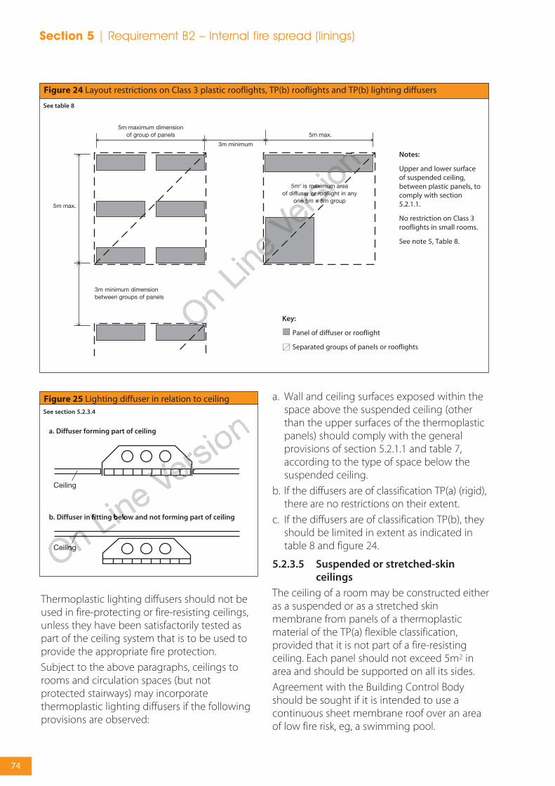
Thermoplastic lighting diffusers should not beused in fire-protecting or fire-resisting ceilings,unless they have been satisfactorily tested aspart of the ceiling system that is to be used toprovide the appropriate fire protection.
Subject to the above paragraphs, ceilings torooms and circulation spaces (but notprotected stairways) may incorporatethermoplastic lighting diffusers if the followingprovisions are observed:
a. Wall and ceiling surfaces exposed within thespace above the suspended ceiling (otherthan the upper surfaces of the thermoplasticpanels) should comply with the generalprovisions of section 5.2.1.1 and table 7,according to the type of space below thesuspended ceiling.
b. If the diffusers are of classification TP(a) (rigid),there are no restrictions on their extent.
c. If the diffusers are of classification TP(b), theyshould be limited in extent as indicated intable 8 and figure 24.
5.2.3.5 Suspended or stretched-skinceilings
The ceiling of a room may be constructed eitheras a suspended or as a stretched skinmembrane from panels of a thermoplasticmaterial of the TP(a) flexible classification,provided that it is not part of a fire-resistingceiling. Each panel should not exceed 5m2 inarea and should be supported on all its sides.
Agreement with the Building Control Bodyshould be sought if it is intended to use acontinuous sheet membrane roof over an areaof low fire risk, eg, a swimming pool.
Figure 24 Layout restrictions on Class 3 plastic rooflights, TP(b) rooflights and TP(b) lighting diffusers
See table 8
Key:
Panel of diffuser or rooflight
Separated groups of panels or rooflights
Notes:
Upper and lower surfaceof suspended ceiling,between plastic panels, tocomply with section5.2.1.1.
No restriction on Class 3rooflights in small rooms.
See note 5, Table 8.
Figure 25 Lighting diffuser in relation to ceilingSee section 5.2.3.4
a. Diffuser forming part of ceiling
b. Diffuser in fitting below and not forming part of ceiling
Section 5 | Requirement B2 – Internal fire spread (linings)
74

Section 6Internal fire spread(structure)

6.1 Overview
6.1.1 Requirement B3 of the BuildingRegulations
(1) The building shall be designed andconstructed so that, in the event of fire, itsstability will be maintained for a reasonableperiod.
(2) A wall common to two or more buildingsshall be designed and constructed so that itadequately resists the spread of fire betweenthose buildings.
(3) Where reasonably necessary to inhibit thespread of fire within the building, measuresshall be taken, to an extent appropriate tothe size and intended use of the building,comprising either or both of the following:
(a) sub-division of the building with fire-resisting construction; and/or
(b) installation of suitable automatic firesuppression systems.
(4) The building shall be designed andconstructed so that the unseen spread of fireand smoke within concealed spaces in itsstructure and fabric is inhibited.
6.1.2 Performance
Requirements of B3 will be met:
a. if the loadbearing elements of structure ofthe building are capable of withstanding theeffects of fire for an appropriate periodwithout loss of stability;
b. if the building is sub-divided by elements offire-resisting construction intocompartments;
c. if any openings in fire-separating elements(see appendix F) are suitably protected inorder to maintain the integrity of theelement (ie, the continuity of the fireseparation); and
d. if any hidden voids in the construction aresealed and sub-divided to inhibit the unseenspread of fire and products of combustion, inorder to reduce the risk of structural failureand the spread of fire, in so far as they pose athreat to the safety of people in and aroundthe building.
The extent to which any of these measures arenecessary is dependent on the use of thebuilding and, in some cases, its size and on thelocation of the element of construction.
Protection of the property and contents againstfire may require the use of fire-resisting glazingwith an insulation performance (rather thanintegrity only) because of the risk of exposure ofthe fabric of the building to prolonged periodsof post-flashover fire conditions.
6.1.3 Introduction
Guidance on loadbearing elements of structureis given in section 6.2. Section 6.3 is concernedwith the sub-division of a building intocompartments and section 6.4 makes provisionsabout concealed spaces (or cavities). Section 6.5gives information on the protection of openingsand on fire-stopping. Common to all thesesections and to other provisions of Part B, is theproperty of fire resistance.
6.1.3.1 Fire resistance
The fire resistance of an element of constructionis a measure of its ability to withstand theeffects of fire in one or more ways, as follows:
• resistance to collapse, ie, the ability tomaintain loadbearing capacity (which appliesto loadbearing elements only) (R);
• resistance to fire penetration, ie, an ability tomaintain the integrity of the element (E); and
• resistance to the transfer of excessive heat, ie,an ability to provide insulation from hightemperatures (I).
‘Elements of structure’ is the term applied to themain structural loadbearing elements, such asstructural frames, floors and loadbearing walls.Compartment walls are treated as elements ofstructure although they are not necessarilyloadbearing. Roofs, unless they serve thefunction of a floor, are not treated as elementsof structure. External walls, such as curtain wallsor other forms of cladding which transmit onlyself weight and wind loads and do not transmitfloor load, are not regarded as loadbearing forthe purposes of this section, although they mayneed fire resistance to satisfy requirement B4(see sections 7.2 and 7.3).
Section 6 | Requirement B3 – Internal fire spread (structure)
76

Loadbearing elements may or may not have afire-separating function. Similarly, fire-separatingelements may or may not be loadbearing.
6.1.3.2 Guidance elsewhere in this guideconcerning fire resistance
There is guidance in sections 4.3 – 4.5concerning the use of fire-resisting constructionto protect means of escape. There is guidancein section 7.2 about fire resistance of externalwalls to restrict the spread of fire betweenbuildings. There is guidance in section 8.4 aboutfire resistance in the construction of fire-fightingshafts. Appendix A gives information onmethods of test and performance for elementsof construction. Appendix C gives informationon fire doors. Appendix E gives information onmethods of measurement. Appendix F givesdefinitions.
6.2 Loadbearing elements ofstructure
6.2.1 Introduction
Premature failure of the structure can beprevented by provisions for loadbearingelements of structure to have a minimumstandard of fire resistance, in terms of resistanceto collapse or failure of loadbearing capacity.The purpose in providing the structure with fireresistance is threefold, namely:
• to minimise the risk to the occupants, someof whom may have to remain in the buildingfor some time while evacuation proceeds ifthe building is a large one;
• to reduce the risk to firefighters, who may beengaged on search or rescue operations;
• to reduce the danger to people in the vicinityof the building, who might be hurt by fallingdebris or as a result of the impact of thecollapsing structure on other buildings; and
• to provide structural resilience against fireand limit the possibility of fire spread.
6.2.2 Fire resistance standard
Elements of structure such as structural frames,beams, columns, loadbearing walls (internal andexternal), floor structures and gallery structures,should have at least the fire resistance given inappendix A, table A1.
6.2.2.1 Application of the fire resistancestandards for loadbearing elements
The measures set out in appendix A includeprovisions to ensure that where one element ofstructure supports or gives stability to anotherelement of structure, the supporting elementhas no less fire resistance than the otherelement (see notes to table A2). The measuresalso provide for elements of structure that arecommon to more than one building orcompartment, to be constructed to thestandard of the greater of the relevantprovisions. Special provisions about fireresistance of elements of structure in singlestorey buildings are also given and there areconcessions in respect of fire resistance ofelements of structure in basements where atleast one side of the basement is open atground level.
6.2.2.2 Exclusions from the provisions forelements of structure
The following are excluded from the definitionof element of structure for the purposes ofthese provisions:
a. a structure that only supports a roof, unless:
i. the roof performs the function of a floor,such as for parking vehicles, or as a meansof escape; or
ii. the structure is essential for the stability ofan external wall which needs to have fireresistance;
b. the lowest floor of the building;
c. a platform floor; and
d. a loading gallery, fly gallery, stage grid,lighting bridge, or any gallery provided forsimilar purposes or for maintenance andrepair (see definition of ‘Element of structure’in appendix F).
Requirement B3 – Internal fire spread (structure) | Section 6
77
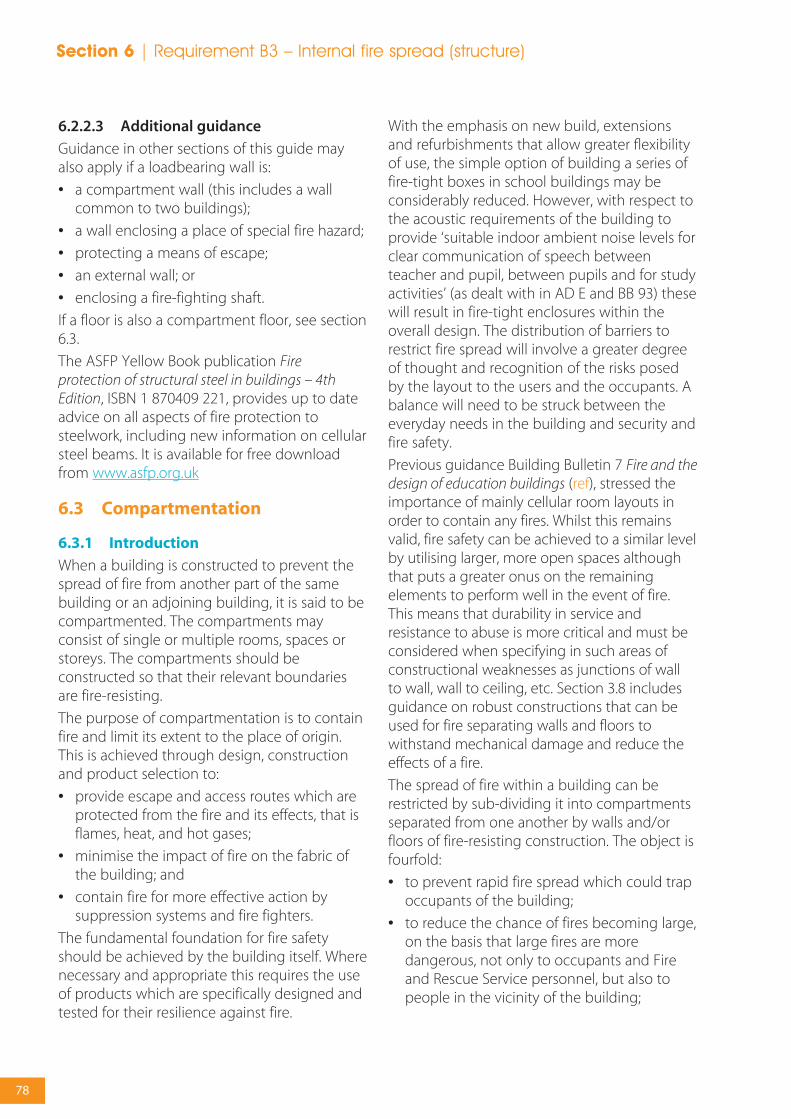
6.2.2.3 Additional guidance
Guidance in other sections of this guide mayalso apply if a loadbearing wall is:
• a compartment wall (this includes a wallcommon to two buildings);
• a wall enclosing a place of special fire hazard;
• protecting a means of escape;
• an external wall; or
• enclosing a fire-fighting shaft.
If a floor is also a compartment floor, see section6.3.
The ASFP Yellow Book publication Fireprotection of structural steel in buildings – 4thEdition, ISBN 1 870409 221, provides up to dateadvice on all aspects of fire protection tosteelwork, including new information on cellularsteel beams. It is available for free downloadfrom www.asfp.org.uk
6.3 Compartmentation
6.3.1 Introduction
When a building is constructed to prevent thespread of fire from another part of the samebuilding or an adjoining building, it is said to becompartmented. The compartments mayconsist of single or multiple rooms, spaces orstoreys. The compartments should beconstructed so that their relevant boundariesare fire-resisting.
The purpose of compartmentation is to containfire and limit its extent to the place of origin.This is achieved through design, constructionand product selection to:
• provide escape and access routes which areprotected from the fire and its effects, that isflames, heat, and hot gases;
• minimise the impact of fire on the fabric ofthe building; and
• contain fire for more effective action bysuppression systems and fire fighters.
The fundamental foundation for fire safetyshould be achieved by the building itself. Wherenecessary and appropriate this requires the useof products which are specifically designed andtested for their resilience against fire.
With the emphasis on new build, extensionsand refurbishments that allow greater flexibilityof use, the simple option of building a series offire-tight boxes in school buildings may beconsiderably reduced. However, with respect tothe acoustic requirements of the building toprovide ‘suitable indoor ambient noise levels forclear communication of speech betweenteacher and pupil, between pupils and for studyactivities’ (as dealt with in AD E and BB 93) thesewill result in fire-tight enclosures within theoverall design. The distribution of barriers torestrict fire spread will involve a greater degreeof thought and recognition of the risks posedby the layout to the users and the occupants. Abalance will need to be struck between theeveryday needs in the building and security andfire safety.
Previous guidance Building Bulletin 7 Fire and thedesign of education buildings (ref), stressed theimportance of mainly cellular room layouts inorder to contain any fires. Whilst this remainsvalid, fire safety can be achieved to a similar levelby utilising larger, more open spaces althoughthat puts a greater onus on the remainingelements to perform well in the event of fire.This means that durability in service andresistance to abuse is more critical and must beconsidered when specifying in such areas ofconstructional weaknesses as junctions of wallto wall, wall to ceiling, etc. Section 3.8 includesguidance on robust constructions that can beused for fire separating walls and floors towithstand mechanical damage and reduce theeffects of a fire.
The spread of fire within a building can berestricted by sub-dividing it into compartmentsseparated from one another by walls and/orfloors of fire-resisting construction. The object isfourfold:
• to prevent rapid fire spread which could trapoccupants of the building;
• to reduce the chance of fires becoming large,on the basis that large fires are moredangerous, not only to occupants and Fireand Rescue Service personnel, but also topeople in the vicinity of the building;
Section 6 | Requirement B3 – Internal fire spread (structure)
78

• to provide protected zones linked byprotected escape ways to a place of safetyoutside the building; and
• to reinforce the stability and resilience of thebuilding fabric against damage by fire so thatit may resist the longer term impact of fireonce the occupants have left the building.
Compartmentation is complementary toprovisions made in sections 4.3 – 4.5 for theprotection of escape routes and to provisionsmade in sections 7.2 – 7.4 against the spread offire between buildings.
Compartmentation is also beneficial in reducingthe extent of fire damage to a building. Otherthan for small premises, insurers may require adegree of compartmentation such that themaximum loss from a fire should never exceed25% of the whole building.
The appropriate degree of sub-division dependson:
• the use of and fire load in the building, whichaffects the potential for fires and the severityof fires, as well as the ease of evacuation;
• the height to the floor of the top storey inthe building, which is an indication of theease of evacuation and the ability of the Fireand Rescue Service to intervene effectively;and
• the availability of a sprinkler system whichaffects the growth rate of the fire and maysuppress it altogether.
Sub-division is achieved using compartmentwalls and compartment floors. Thecircumstances in which they are needed aregiven in sections 6.3.2.1 – 6.3.2.3.
Provisions for the construction of compartmentwalls and compartment floors are given insections 6.3.3.1 onwards. These constructionprovisions vary according to the function of thewall or floor.
6.3.1.1 Special forms of compartmentation
Special forms of compartmentation to whichparticular construction provisions apply, are:
a. walls common to two or more buildings, seesection 6.3.2.1;
b. walls dividing buildings into separated parts,see section 6.3.2.1; and
c. construction enclosing places of special firehazard, see section 6.3.2.2.
6.3.1.2 Junctions
For compartmentation to be effective, thereshould be continuity at the junctions of the fire-resisting elements enclosing a compartmentand any openings from one compartment toanother should not present a weakness.
Excessive deflections should be prevented, asthese will tend to jeopardise the requirementfor compartment integrity. Large deflections willalso make it more difficult to successfully carryout building refurbishment following a fire. Forfurther recommendations on dealing withdeflections, see appendix 3D of the LPC DesignGuide for the Fire Protection of Buildings (ref).
6.3.1.3 Protected shafts
Spaces that connect compartments, such asstairways and service shafts, need to beprotected to restrict fire spread between thecompartments and they are termed protectedshafts. Any walls or floors bounding a protectedshaft are considered to be compartment wallsor floors.
6.3.1.4 Buildings containing one or moreatria
Detailed advice on all issues relating to theincorporation of atria in buildings is given in BS5588-7:1997. However, it should be noted thatfor life safety purposes, the standard is relevantonly where the atrium breaches anycompartmentation.
A fire engineering solution should be usedwhenever unusual materials or designs areused, eg, ETFE for roofs. See also The design andprotection of new school buildings and sites, 2005(ref).
Requirement B3 – Internal fire spread (structure) | Section 6
79

6.3.2 Provision of compartmentation
The maximum dimensions of compartmentswithin schools are given in table 9.
Note: ‘Sprinklered’ means that the school is fittedthroughout with an automatic system meeting therelevant recommendations of the SSLD on Spinklers inSchools (ref) plus requirements for ‘life safety’. The benefitto the designer from the installation of such asuppression system is that compartments can more thandouble in size.
6.3.2.1 General
Compartment walls and compartment floorsshould be provided in the circumstancesdescribed below, with the proviso that thelowest floor in a building does not need to beconstructed as a compartment floor, providedthere is no basement. Sections 6.3.2.1 – 6.3.2.3give guidance on the provision ofcompartmentation in different building types.Information on the construction ofcompartment walls and compartment floors indifferent circumstances is given in sections6.3.3.1 – 6.3.3.6. Provisions for the protection ofopenings in compartment walls andcompartment floors are given in sections 6.3.4.1– 6.3.4.3.
A wall common to two or more buildingsshould be constructed as a compartment wall.
Parts of a building that are occupied mainly fordifferent purposes should be separated fromone another by compartment walls and/orcompartment floors. This does not apply whereone of the different purposes is ancillary to theother.
In order to reduce the extent of propertydamage, all floors in unsprinklered schoolsshould be compartment floors.
6.3.2.2 Places of special fire risk
Every place of special fire hazard (see section 3.1and appendix F) should be enclosed with fire-resisting construction; see table A1, item 12, inappendix A.
Consideration should also be given to the fireprotection of parts of the building housingvaluable assets, in order to reduce propertydamage and/or business interruption followinga fire.
Parts of the school used out of normal hours byschool clubs or members of the public could beconsidered as higher risk, by virtue of the factthat they are in use for longer periods of theday. If these parts form separate compartments,the benefits for property protection are twofold:
• there is less chance that a fire starting in thearea used outside normal school hours willspread to the rest of the school; and
• there is less chance that a fire startingelsewhere in the school will spread to affectthe areas of community use.
Note: Any such walls and floors are notcompartment walls and compartment floors.
Table 9 Maximum dimensions of compartmentswithin schools
Floor area of any one storey in the school or any onestorey in a compartment (m2)
In multi-storey schools
Not sprinklered – 800
Sprinklered – 2000
In single storey schools
Not sprinklered – 800
Sprinklered – No limit
Figure 26 Compartment floors: Illustration ofguidance in section 6.3.2.3.
a. Example of compartmentation inan unsprinklered school (seesection 6.3.2.3a)
For life safety, none of the floors in this case would need to be compartment floors, butthe two storeys exceeding 800m2 would need to be divided into compartments not more than 800m2 bycompartment walls.
In order to reduce the extent of property damage, all floors in unsprinklered schoolsshould be compartment floors.
b. Shallow basement (see section6.3.2.3b)
Only the floor of the ground floor needbe a compartment floor if the lowerbasement is at a depth of not more than10m.
Section 6 | Requirement B3 – Internal fire spread (structure)
80

6.3.2.3 General
The following walls and floors should beconstructed as compartment walls andcompartment floors:
• every wall needed to sub-divide the buildingto observe the size limits on compartmentsgiven in table 9 (see figure 26a); and
• the floor of the ground storey if the buildinghas one or more basements (see figure 26b).
6.3.3 Construction of compartment wallsand compartment floors
6.3.3.1 General
Every compartment wall and compartmentfloor should:
• form a complete barrier to fire between thecompartments they separate; and
• have the appropriate fire resistance asindicated in appendix A, tables A1 and A2.
Note 1: Timber beams, joists, purlins and raftersmay be built into or carried through a masonryor concrete compartment wall if the openingsfor them are kept as small as practicable andthen fire-stopped. If trussed rafters bridge thewall, they should be designed so that failure ofany part of the truss due to a fire in onecompartment will not cause failure of any partof the truss in another compartment.
Note 2: Where services are incorporated withinthe construction that could provide a potentialsource of ignition, care should be taken toensure the risk of fire developing and spreading
prematurely into adjacent compartments iscontrolled.
Additional recommendations for propertyprotection and the minimisation of disruptionare that compartment walls and floors shouldbe constructed of robust materials (see section3.8) to withstand accidental and mechanicaldamage, and that in the event of a fire theyshould be capable of being reinstated withminimal disturbance to adjoining buildings.
6.3.3.2 Compartment walls betweenbuildings
Compartment walls that are common to two ormore buildings should run the full height of thebuilding in a continuous vertical plane. Thusadjoining buildings should only be separated bywalls, not floors.
6.3.3.3 Separated parts of buildings
Compartment walls used to form a separatedpart of a building (so that the separated partscan be assessed independently for the purposeof determining the appropriate standard of fireresistance) should run the full height of thebuilding in a continuous vertical plane. The twoseparated parts may have different standards offire resistance.
6.3.3.4 Other compartment walls
Compartment walls not described in sections6.3.3.2 and 6.3.3.3 should run the full height ofthe storey in which they are situated.
Compartment walls in a top storey beneath aroof should be continued through the roofspace (see definition of compartment inappendix F).
6.3.3.5 Junction of compartment wall orcompartment floor with other walls
Where a compartment wall or compartmentfloor meets another compartment wall or anexternal wall, the junction should maintain thefire resistance of the compartmentation. Fire-stopping should meet the provisions of section6.5.4.
At the junction of a compartment floor with anexternal wall that has no fire resistance (such asa curtain wall) the external wall should berestrained at floor level to reduce the
Figure 27 Compartment walls and compartmentfloors with reference to relevant sections of 6.3
Requirement B3 – Internal fire spread (structure) | Section 6
81
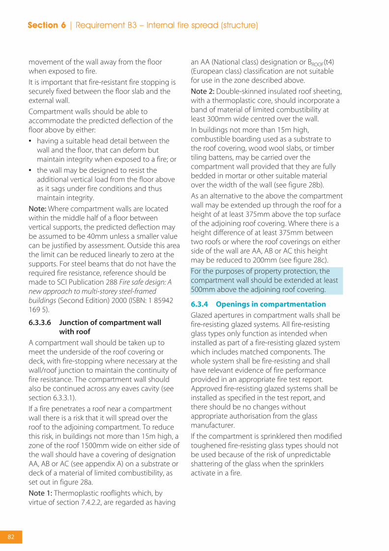
movement of the wall away from the floorwhen exposed to fire.
It is important that fire-resistant fire stopping issecurely fixed between the floor slab and theexternal wall.
Compartment walls should be able toaccommodate the predicted deflection of thefloor above by either:
• having a suitable head detail between thewall and the floor, that can deform butmaintain integrity when exposed to a fire; or
• the wall may be designed to resist theadditional vertical load from the floor aboveas it sags under fire conditions and thusmaintain integrity.
Note: Where compartment walls are locatedwithin the middle half of a floor betweenvertical supports, the predicted deflection maybe assumed to be 40mm unless a smaller valuecan be justified by assessment. Outside this areathe limit can be reduced linearly to zero at thesupports. For steel beams that do not have therequired fire resistance, reference should bemade to SCI Publication 288 Fire safe design: Anew approach to multi-storey steel-framedbuildings (Second Edition) 2000 (ISBN: 1 85942169 5).
6.3.3.6 Junction of compartment wall with roof
A compartment wall should be taken up tomeet the underside of the roof covering ordeck, with fire-stopping where necessary at thewall/roof junction to maintain the continuity offire resistance. The compartment wall shouldalso be continued across any eaves cavity (seesection 6.3.3.1).
If a fire penetrates a roof near a compartmentwall there is a risk that it will spread over theroof to the adjoining compartment. To reducethis risk, in buildings not more than 15m high, azone of the roof 1500mm wide on either side ofthe wall should have a covering of designationAA, AB or AC (see appendix A) on a substrate ordeck of a material of limited combustibility, asset out in figure 28a.
Note 1: Thermoplastic rooflights which, byvirtue of section 7.4.2.2, are regarded as having
an AA (National class) designation or BROOF(t4)(European class) classification are not suitablefor use in the zone described above.
Note 2: Double-skinned insulated roof sheeting,with a thermoplastic core, should incorporate aband of material of limited combustibility atleast 300mm wide centred over the wall.
In buildings not more than 15m high,combustible boarding used as a substrate tothe roof covering, wood wool slabs, or timbertiling battens, may be carried over thecompartment wall provided that they are fullybedded in mortar or other suitable materialover the width of the wall (see figure 28b).
As an alternative to the above the compartmentwall may be extended up through the roof for aheight of at least 375mm above the top surfaceof the adjoining roof covering. Where there is aheight difference of at least 375mm betweentwo roofs or where the roof coverings on eitherside of the wall are AA, AB or AC this heightmay be reduced to 200mm (see figure 28c).
For the purposes of property protection, thecompartment wall should be extended at least500mm above the adjoining roof covering.
6.3.4 Openings in compartmentation
Glazed apertures in compartment walls shall befire-resisting glazed systems. All fire-resistingglass types only function as intended wheninstalled as part of a fire-resisting glazed systemwhich includes matched components. Thewhole system shall be fire-resisting and shallhave relevant evidence of fire performanceprovided in an appropriate fire test report.Approved fire-resisting glazed systems shall beinstalled as specified in the test report, andthere should be no changes withoutappropriate authorisation from the glassmanufacturer.
If the compartment is sprinklered then modifiedtoughened fire-resisting glass types should notbe used because of the risk of unpredictableshattering of the glass when the sprinklersactivate in a fire.
Section 6 | Requirement B3 – Internal fire spread (structure)
82
6.3.4.1 Openings in compartment wallsseparating buildings oroccupancies
Any openings in a compartment wall which iscommon to two or more buildings, or betweendifferent occupancies in the same building,should be limited to those for:
a. a door which is needed to provide a meansof escape in case of fire and which has thesame fire resistance as that required for the
wall (see appendix C, table C1) and is fitted inaccordance with the provisions of appendixC; and
b. the passage of a pipe which meets theprovisions in section 6.5.
6.3.4.2 Doors
Information on fire doors may be found inappendix C.
6.3.4.3 Openings in other compartmentwalls or in compartment floors
Openings in compartment walls (other thanthose described in section 6.3.4.1) orcompartment floors should be limited to thosefor:
a. doors which have the appropriate fireresistance given in appendix C, table C1 andare fitted in accordance with the provisionsof appendix C;
b. the passage of pipes, ventilation ducts,service cables, chimneys, applianceventilation ducts or ducts encasing one ormore flue pipes, which meet the provisionsin section 6.4;
c. refuse chutes of non-combustibleconstruction;
d. atria designed in accordance with BS 5588-7:1997; and
e. protected shafts which meet the relevantprovisions below.
6.3.5 Protected shafts
Any stairway or other shaft passing directly fromone compartment to another should beenclosed in a protected shaft so as to delay orprevent the spread of fire betweencompartments.
There are additional provisions in sections 4.3 – 4.5 for protected shafts that are protectedstairways and in section 8.4 if the stairway alsoserves as a fire-fighting stair.
6.3.5.1 Uses for protected shafts
The uses of protected shafts should berestricted to stairs, lifts, escalators, chutes, ductsand pipes. Sanitary accommodation andwashrooms may be included in protectedshafts.
X
X
Figure 28 Junction of compartment wall with roof
b. Building notmore than 15mhigh
c. Any building orcompartment
Section X-X
a. Any building orcompartment
See section 6.3.3.6Roof covering over this distance to bedesignated AA, AB or AC on deck of materialof limited combustibility. Roof covering anddeck could be composite structure, eg,profiled steel cladding.Double skinned insulated roof sheetingcould incorporate a band of material oflimited combustibility at least 300mm widecentred over the wall.If roof support members pass through thewall, fire protection to these members for adistance of 1500mm on either side of thewall may be needed to delay distortion atthe junction (see note to section 6.3.3.1).Resilient fire-stopping to be carried up to theunderside of roof covering, eg, roof tiles.
Roof covering to be designated AA, AB orAC for at least this distance.Boarding (used as a substrate), wood woolslabs or timber tiling battens may be carriedover the wall provided that they are fullybedded in mortar (or other no less suitablematerial) where over the wall.Sarking felt may also be carried over thewall.If roof support members pass through thewall, fire protection to these members for adistance of 1500mm on either side of thewall may be needed to delay distortion atthe junction (see note to section 6.3.3.1).Fire-stopping to be carried up to theunderside of the roof covering, boarding orslab.
Roof covering to be designated AA, AB orAC for at least 1500mm either side of thewall.Roof battens and sarking felt may be carriedover the wall.Fire-stopping to be carried up to theunderside of roof covering. Above andbelow sarking felt.Notes:1. Fire-stopping should be carried over thefull thickness of the wall.2. Fire-stopping should be extended intoany eaves3. The compartment wall need notnecessarily be constructed out of masonry.
The wall should be extended up throughthe roof for a height of at least 375mmabove the top surface of the adjoining roofcovering.Where there is a height difference of at least375mm between two roofs or where theroof coverings on either side of the wall areAA, AB or AC the height of theupstand/parapet wall above the highestroof may be reduced to 200mm.
Requirement B3 – Internal fire spread (structure) | Section 6
83

6.3.5.2 Construction of protected shafts
The construction enclosing a protected shaft(see figure 29) should:
a. form a complete barrier to fire between thedifferent compartments which the shaftconnects;
b. have the appropriate fire resistance given inappendix A, table A1, except for uninsulatedglazed screens which meet the provisions ofsection 6.3.5.3; and
c. satisfy the provisions about their ventilationand the treatment of openings in section6.3.5.5 – 6.3.5.6.
6.3.5.3 Uninsulated glazed screens toprotected shafts
If the conditions given below are satisfied, anuninsulated glazed screen may be incorporatedin the enclosure to a protected shaft between astair and a lobby or corridor which is enteredfrom the stair. The conditions to be satisfied are:
a. the recommended standard of fire resistancefor the stair enclosure is not more than 60minutes; and
b. the glazed screen:
i. has at least 30 minutes fire resistance interms of integrity; and
ii. meets the guidance in appendix A, tableA4, on the limits on areas of uninsulatedglazing; and
c. the lobby or corridor is enclosed to at least a30 minute standard.
If the above measures to protect the lobby orcorridor are not provided, the enclosing wallsshould comply with appendix A, table A1 (item7c) and the doors with the guidance in appendixA, table A4.
6.3.5.4 Pipes for oil or gas and ventilationducts in protected shafts
If a protected shaft contains a stair and/or a lift, itshould not also contain a pipe conveying oil(other than in the mechanism of a hydraulic lift)or contain a ventilating duct (other than a ductprovided for the purposes of pressurizing thestairway to keep it smoke free; or a ductprovided solely for ventilating the stairway).
Any pipe carrying natural gas or LPG in such ashaft should be of screwed steel or of all weldedsteel construction, installed in accordance withthe Pipelines Safety Regulations 1996, SI 1996 No 825 and the Gas Safety (Installation and use)Regulations 1998, SI 1998 No 2451.
Note: A pipe is not considered to be containedwithin a protected shaft if the pipe is completelyseparated from that protected shaft by fire-resisting construction.
Figure 29 Protected Shafts
Protected shafts provide for the movement of people (eg, stairs, lifts), or for passage of goods, air or services such as pipe or cablesbetween different compartments. The elements enclosing the shaft (unless formed by adjacent external walls) are compartment walls andfloors. The figure shows three common examples which illustrate the principles.
The shaft structure (including any openings) should meet the relevant provisions for: compartment walls (see sections 6.3.3.1 to 6.3.4.3),external walls (see sections 7.2 and 7.3 and figure 22).
See section 6.3.5 – 6.5.3.2
Section 6 | Requirement B3 – Internal fire spread (structure)
84
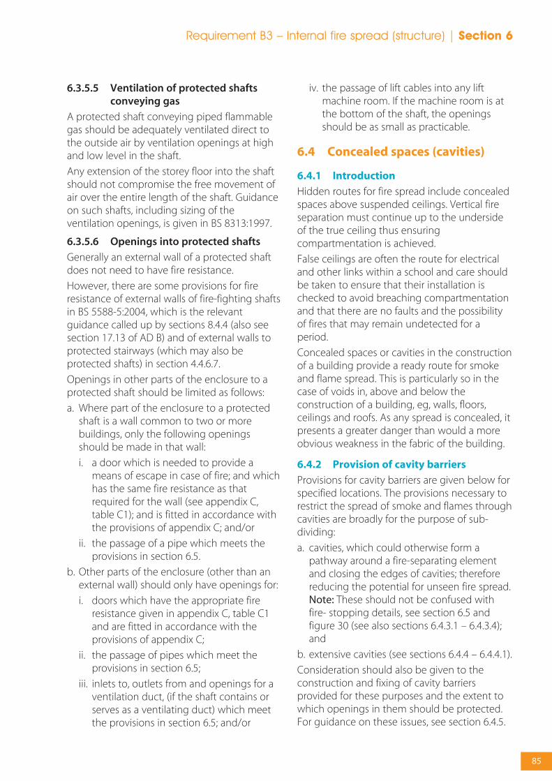
6.3.5.5 Ventilation of protected shaftsconveying gas
A protected shaft conveying piped flammablegas should be adequately ventilated direct tothe outside air by ventilation openings at highand low level in the shaft.
Any extension of the storey floor into the shaftshould not compromise the free movement ofair over the entire length of the shaft. Guidanceon such shafts, including sizing of theventilation openings, is given in BS 8313:1997.
6.3.5.6 Openings into protected shafts
Generally an external wall of a protected shaftdoes not need to have fire resistance.
However, there are some provisions for fireresistance of external walls of fire-fighting shaftsin BS 5588-5:2004, which is the relevantguidance called up by sections 8.4.4 (also seesection 17.13 of AD B) and of external walls toprotected stairways (which may also beprotected shafts) in section 4.4.6.7.
Openings in other parts of the enclosure to aprotected shaft should be limited as follows:
a. Where part of the enclosure to a protectedshaft is a wall common to two or morebuildings, only the following openingsshould be made in that wall:
i. a door which is needed to provide ameans of escape in case of fire; and whichhas the same fire resistance as thatrequired for the wall (see appendix C,table C1); and is fitted in accordance withthe provisions of appendix C; and/or
ii. the passage of a pipe which meets theprovisions in section 6.5.
b. Other parts of the enclosure (other than anexternal wall) should only have openings for:
i. doors which have the appropriate fireresistance given in appendix C, table C1and are fitted in accordance with theprovisions of appendix C;
ii. the passage of pipes which meet theprovisions in section 6.5;
iii. inlets to, outlets from and openings for aventilation duct, (if the shaft contains orserves as a ventilating duct) which meetthe provisions in section 6.5; and/or
iv. the passage of lift cables into any liftmachine room. If the machine room is atthe bottom of the shaft, the openingsshould be as small as practicable.
6.4 Concealed spaces (cavities)
6.4.1 Introduction
Hidden routes for fire spread include concealedspaces above suspended ceilings. Vertical fireseparation must continue up to the undersideof the true ceiling thus ensuringcompartmentation is achieved.
False ceilings are often the route for electricaland other links within a school and care shouldbe taken to ensure that their installation ischecked to avoid breaching compartmentationand that there are no faults and the possibilityof fires that may remain undetected for aperiod.
Concealed spaces or cavities in the constructionof a building provide a ready route for smokeand flame spread. This is particularly so in thecase of voids in, above and below theconstruction of a building, eg, walls, floors,ceilings and roofs. As any spread is concealed, itpresents a greater danger than would a moreobvious weakness in the fabric of the building.
6.4.2 Provision of cavity barriers
Provisions for cavity barriers are given below forspecified locations. The provisions necessary torestrict the spread of smoke and flames throughcavities are broadly for the purpose of sub-dividing:
a. cavities, which could otherwise form apathway around a fire-separating elementand closing the edges of cavities; thereforereducing the potential for unseen fire spread.Note: These should not be confused withfire- stopping details, see section 6.5 andfigure 30 (see also sections 6.4.3.1 – 6.4.3.4);and
b. extensive cavities (see sections 6.4.4 – 6.4.4.1).
Consideration should also be given to theconstruction and fixing of cavity barriersprovided for these purposes and the extent towhich openings in them should be protected.For guidance on these issues, see section 6.4.5.
Requirement B3 – Internal fire spread (structure) | Section 6
85
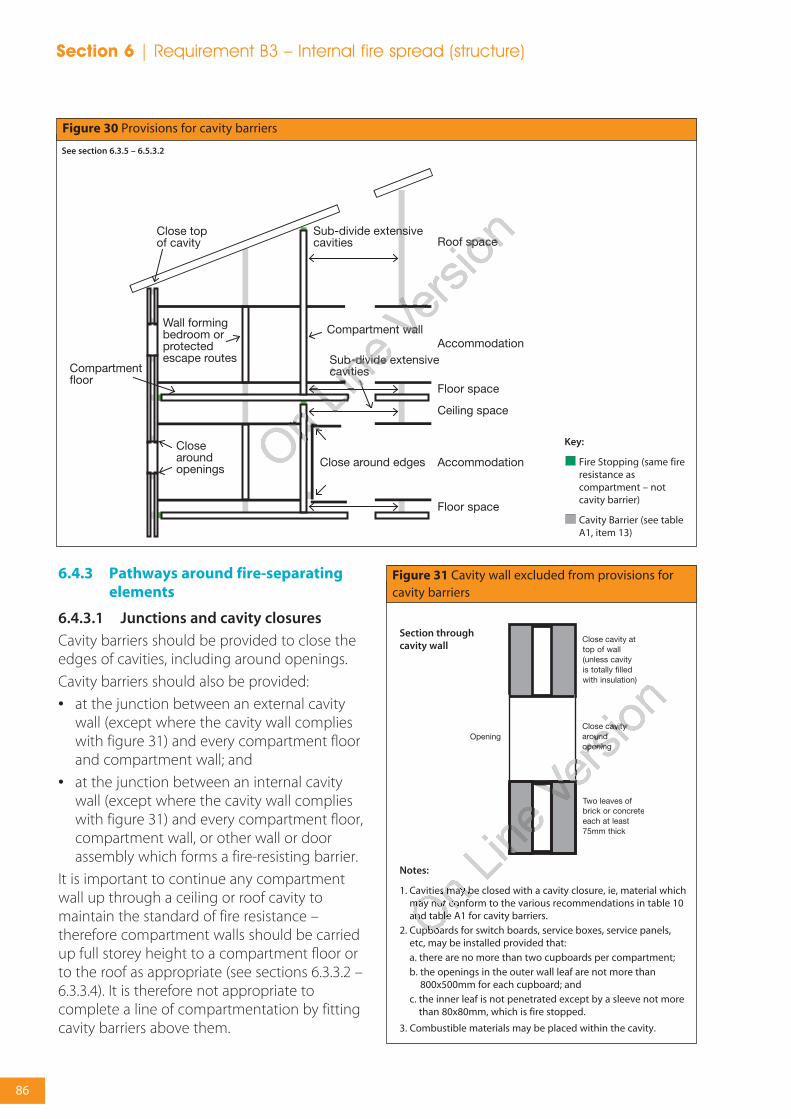
6.4.3 Pathways around fire-separatingelements
6.4.3.1 Junctions and cavity closures
Cavity barriers should be provided to close theedges of cavities, including around openings.
Cavity barriers should also be provided:
• at the junction between an external cavitywall (except where the cavity wall complieswith figure 31) and every compartment floorand compartment wall; and
• at the junction between an internal cavitywall (except where the cavity wall complieswith figure 31) and every compartment floor,compartment wall, or other wall or doorassembly which forms a fire-resisting barrier.
It is important to continue any compartmentwall up through a ceiling or roof cavity tomaintain the standard of fire resistance –therefore compartment walls should be carriedup full storey height to a compartment floor orto the roof as appropriate (see sections 6.3.3.2 –6.3.3.4). It is therefore not appropriate tocomplete a line of compartmentation by fittingcavity barriers above them.
Close topof cavity
Sub-divide extensivecavities
Sub-divide extensivecavities
Compartment wall
Roof space
Accommodation
Accommodation
Floor space
Floor space
Ceiling space
Compartmentfloor
Close around edgesClose aroundopenings
Wall formingbedroom orprotectedescape routes
Figure 30 Provisions for cavity barriers
See section 6.3.5 – 6.5.3.2
Key:
Fire Stopping (same fireresistance ascompartment – notcavity barrier)
Cavity Barrier (see tableA1, item 13)
Figure 31 Cavity wall excluded from provisions forcavity barriers
Notes:
1. Cavities may be closed with a cavity closure, ie, material whichmay not conform to the various recommendations in table 10and table A1 for cavity barriers.
2. Cupboards for switch boards, service boxes, service panels,etc, may be installed provided that:a. there are no more than two cupboards per compartment;b. the openings in the outer wall leaf are not more than
800x500mm for each cupboard; andc. the inner leaf is not penetrated except by a sleeve not more
than 80x80mm, which is fire stopped.
3. Combustible materials may be placed within the cavity.
Section throughcavity wall
Section 6 | Requirement B3 – Internal fire spread (structure)
86

6.4.3.2 Protected escape routes
For a protected escape route, a cavity that existsabove or below any fire-resisting constructionbecause the construction is not carried to fullstorey height or, in the case of a top storey, tothe underside of the roof covering, shouldeither be:
a. fitted with cavity barriers on the line of theenclosure(s) to the protected escape route; or
b. for cavities above the fire-resistingconstruction, enclosed on the lower side by afire-resisting ceiling which extendsthroughout the building, compartment orseparated part (see figure 32).
6.4.3.3 Double-skinned corrugated orprofiled roof sheeting
Cavity Barriers need not be provided betweendouble-skinned corrugated or profiled insulatedroof sheeting, if the sheeting is a material oflimited combustibility and both surfaces of theinsulating layer have a surface spread of flameof at least Class 0 or 1 (National class) or Class C-s3, d2 or better (European class) (see appendixA) and make contact with the inner and outerskins of cladding (see figure 33).
Note: See also section 6.3.3.6, note 2 regardingthe junction of a compartment wall with a roof.
Note: When a classification includes ‘s3, d2’, thismeans that there is no limit set for smokeproduction and/or flaming droplets/particles.
6.4.3.4 Cavities affecting alternativeescape routes
Cavity barriers may be needed where corridorsare sub-divided to prevent alternative escaperoutes being simultaneously affected by fireand/or smoke (see section 4.3.2.16 and figure 18).
6.4.4 Extensive cavities
Cavity barriers should be used to sub-divide anycavity, including any roof space, so that thedistance between cavity barriers does notexceed the dimensions given in table 10.
6.4.4.1 Maximum dimensions of concealed spaces
Table 10 sets out maximum dimensions forundivided concealed spaces. With the exceptionsgiven in the rest of this section, extensiveconcealed spaces should be sub-divided tocomply with the dimensions in table 10.
The provisions in table 10 do not apply to anycavity described below:
a. in a wall which should be fire-resisting onlybecause it is loadbearing;
b. in a masonry or concrete external cavity wallshown in figure 31;
c. in any floor or roof cavity above a fire-resisting ceiling, as shown in figure 32 andwhich extends throughout the building orcompartment subject to a 30m limit on theextent of the cavity; or
Maximum dimensions inany direction (m)
20
20
10
Location of cavity
Between a roof and aceiling
Any other cavity
National class
Any
Class 0 or Class 1
Not Class 0 or Class 1
European class
Any
Class A1 or Class A2-s3,d2 or Class B-s3,d2 or Class C-s3,d2
Not any of the aboveclasses
Table 10 Maximum dimensions of cavities
Class of surface/product exposed in cavity (excluding thesurface of any pipe, cable or conduit, or any insulation toany pipe)
Notes:
1. Exceptions to these provisions are given in section6.4.4.1.
2. The national classifications do not automaticallyequate with the equivalent classifications in theEuropean column, therefore products cannot typically
assume a European class unless they have been testedaccordingly.
3. When a classification includes ‘s3, d2’, this means thatthere is no limit set for smoke production and/orflaming droplets/particles.
Requirement B3 – Internal fire spread (structure) | Section 6
87

d. formed behind the external skin of anexternal cladding system with a masonry orconcrete inner leaf at least 75mm thick, or byovercladding an existing masonry (orconcrete) external wall, or an existingconcrete roof, provided that the cavity doesnot contain combustible insulation; or
e. between double-skinned corrugated orprofiled insulated roof sheeting, if thesheeting is a material of limitedcombustibility and both surfaces of theinsulating layer have a surface spread offlame of at least Class 0 or 1 (National class)or Class C-s3, d2 or better (European class)(see appendix A) and make contact with theinner and outer skins of cladding (see figure33); or
f. below a floor next to the ground or oversiteconcrete, if the cavity is less than 1000mm inheight or if the cavity is not normally
accessible by persons, unless there areopenings in the floor such that it is possiblefor combustibles to accumulate in the cavity(in which case cavity barriers should beprovided and access should be provided tothe cavity for cleaning).
Note: When a classification includes ‘s3, d2’, thismeans that there is no limit set for smokeproduction and/or flaming droplets/particles.
Where any single room with a ceiling cavity orunderfloor service void exceeds the dimensionsgiven in table 10, cavity barriers need only beprovided on the line of the enclosingwalls/partitions of that room, subject to:
a. the cavity barriers being no more than 40mapart; and
b. the surface of the material/product exposedin the cavity being Class 0 or Class 1 (Nationalclass) or Class C-s3, d2 or better (Europeanclass).
Note: When a classification includes ‘s3, d2’, thismeans that there is no limit set for smokeproduction and/or flaming droplets/particles.
Where the concealed space is an undividedarea which exceeds 40m (this may be in both
Figure 33 Provisions for cavity barriers in double-skinned insulated roof sheeting
a. Acceptable without cavity barriers
See section 6.4.4.1
b. Cavity barriers necessary
The insulation should make contact with both skins of sheeting.Also see figure 28a regarding the need for a fire break wheresuch roofs pass over the top of a compartment.
Figure 32 Fire-resisting ceiling below concealed space
See section 6.4.4.1
Notes:
1. The ceiling should:a. have at least 30 minutes fire-resistance;b. be imperforate, except for an opening described in section
6.4.5;c. extend throughout the building or compartment; andd. not be easily demountable.
2. The National classifications do not automatically equate withthe equivalent classifications in the European column, thereforeproducts cannot typically assume a European class unless theyhave been tested accordingly.
3. When a classification includes ‘s3, d2’, this means that there isno limit set for smoke production and/or flamingdroplets/particles.
Section 6 | Requirement B3 – Internal fire spread (structure)
88

directions on plan) there is no limit to the sizeof the cavity if:
a. the room and the cavity together arecompartmented from the rest of thebuilding;
b. an automatic fire detection and alarm systemmeeting the relevant recommendations of BS5839-1:2002 is fitted in the building.Detectors are only required in the cavity tosatisfy BS 5839-1;
c. the cavity is used as a plenum and therecommendations about recirculating airdistribution systems in BS 5588-9:1999 arefollowed;
d. the surface of the material/product used inthe construction of the cavity which isexposed in the cavity is Class 0 (Nationalclass) or Class B-s3, d2 or better (Europeanclass) and the supports and fixings in thecavity are of non-combustible construction;
e. the flame spread rating of any pipe insulationsystem is Class 1 or Class C-s3, d2 or better(European class) (see appendix A);
f. any electrical wiring in the void is laid inmetal trays, or in metal conduit; and
g. any other materials in the cavity are oflimited combustibility or Class A2 or better(European class) (see appendix A).
Note: When a classification includes ‘s3, d2’, thismeans that there is no limit set for smokeproduction and/or flaming droplets/particles.
6.4.5 Construction and fixings for cavitybarriers
Every cavity barrier should be constructed toprovide at least 30 minutes fire resistance. Itmay be formed by any construction providedfor another purpose if it meets the provisionsfor cavity barriers (see appendix A, table A1,item 13).
Cavity barriers in a stud wall or partition, orprovided around openings may be formed of:
a. steel at least 0.5mm thick;
b. timber at least 38mm thick;
c. polythene-sleeved mineral wool, or mineralwool slab, in either case under compressionwhen installed in the cavity; or
d. calcium silicate, cement-based or gypsum-based boards at least 12mm thick.
Note: Cavity barriers provided around openingsmay be formed by the window or door frame ifthe frame is constructed of steel or timber ofthe minimum thickness in a) or b) above asappropriate.
A cavity barrier should, wherever possible, betightly fitted to a rigid construction andmechanically fixed in position. Where this is notpossible (for example, in the case of a junctionwith slates, tiles, corrugated sheeting or similarmaterials) the junction should be fire-stopped.Provisions for fire-stopping are set out in section6.5.
Cavity barriers should also be fixed so that theirperformance is unlikely to be made ineffectiveby:
a. movement of the building due tosubsidence, shrinkage or temperaturechange and movement of the externalenvelope due to wind;
b. collapse in a fire of any services penetratingthem;
c. failure in a fire of their fixings (but see notebelow); and
d. failure in a fire of any material or constructionwhich they abut. (For example, if asuspended ceiling is continued over the topof a fire-resisting wall or partition and directconnection is made between the ceiling andthe cavity barrier above the line of the wall orpartition, premature failure of the cavitybarrier can occur when the ceiling collapses.However, this may not arise if the ceiling isdesigned to provide fire protection of 30minutes or more.)
Note: Where cavity barriers are provided in roofspaces, the roof members to which they arefitted are not expected to have any fireresistance – for the purpose of supporting thecavity barrier(s).
Any openings in a cavity barrier should belimited to those for:
• doors which have at least 30 minutes fireresistance (see appendix C, table C1, item 8)and are fitted in accordance with theprovisions of appendix C;
Requirement B3 – Internal fire spread (structure) | Section 6
89

(c) Any other material
40
40
Situation
1. Structure (but not a wallseparating buildings)enclosing a protectedshaft which is not astairway or a lift shaft
2. Any other situation
(a) Non-combustiblematerial(1)
160
160
(b) Lead, aluminium,aluminium alloy, uPVC(2),fibre cement
110
40
Table 11 Maximum nominal internal diameter of pipes passing through a compartment wall/floor (see section6.5.2 onwards)
Pipe material and maximum nominal internal diameter (mm)
Notes:
1. Any non-combustible material (such as cast iron,copper or steel) which, if exposed to a temperature of800°C, will not soften or fracture to the extent thatflame or hot gas will pass through the wall of the pipe.
2. uPVC pipes complying with BS 4514:2001 and uPVCpipes complying with BS 5255:1989.
• the passage of pipes which meet theprovisions in section 6.5;
• the passage of cables or conduits containingone or more cables;
• openings fitted with a suitably mountedautomatic fire damper (see section 6.5.3.1);and
• ducts which (unless they are fire-resisting) arefitted with a suitably mounted automatic firedamper where they pass through the cavitybarrier.
6.5 Protection of openings and fire-stopping
6.5.1 Introduction
Sections 6.3 and 6.4 make provisions for fire-separating elements and set out thecircumstances in which there may be openingsin them. This section deals with the protectionof openings in such elements.
If a fire-separating element is to be effective,every joint or imperfection of fit, or opening toallow services to pass through the element,should be adequately protected by sealing orfire-stopping so that the fire resistance of theelement is not impaired.
The measures in this section are intended todelay the passage of fire. They generally havethe additional benefit of retarding smokespread, but the test specified in appendix A forintegrity does not directly stipulate criteria forthe passage of smoke.
Detailed guidance on door openings and firedoors is given in appendix C.
6.5.2 Openings for pipes
Pipes which pass through a fire-separatingelement (unless the pipe is in a protected shaft),should meet the appropriate provisions inalternatives A, B or C below.
For property protection, pipes and services thatpenetrate through compartment floors shouldbe additionally enclosed within fire-resistingducts.
6.5.2.1 Alternative A: Proprietary seals(any pipe diameter)
Provide a proprietary sealing system which hasbeen shown by test to maintain the fireresistance of the wall, floor or cavity barrier.
Where non-metal pipes penetrate the elementthese shall be fitted with a heat activatedclosure system where test evidence shows theperformance is suitable for the end use. Suchdevices shall be fixed back to the structure sothey will not be readily exposed to fire.Although guidance in support of regulationspermits the use of low melting point pipes ofup to 40mm diameter to penetrate elementswithout the use of special sealing devices, solelyfor life safety purposes, the risk ofdisproportionate fire and smoke damage to theproperty and contents must be considered ifthis option is adopted.
Section 6 | Requirement B3 – Internal fire spread (structure)
90

6.5.2.2 Alternative B: Pipes with arestricted diameter
Where a proprietary sealing system is not used,fire-stopping may be used around the pipe,keeping the opening as small as possible. Thenominal internal diameter of the pipe shouldnot be more than the relevant dimension givenin table 11.
The diameters given in table 11 for pipes ofspecification (b) used in situation (2) assumesthat the pipes are part of an above grounddrainage system and are enclosed as shown infigure 35 if they are not, the smaller diametergiven for situation (3) should be used.
6.5.2.3 Alternative C: Sleeving
A pipe of lead, aluminium, aluminium alloy,fibre-cement or uPVC, with a maximum nominalinternal diameter of 160mm, may be used witha sleeving of non-combustible pipe as shown infigure 34. The specification for non-combustibleand uPVC pipes is given in the notes to table 11.
6.5.3 Ventilation ducts, flues, etc.
Where air handling ducts pass through fireseparating elements the integrity of thoseelements should be maintained.
There are three basic methods and these are:
Method 1 Protection using fire dampers;
Method 2 Protection using fire-resistingenclosures;
Method 3 Protection using fire-resistingductwork.
Method 1 is not suitable for extract ductworkserving kitchens. This is due to the likely build upof grease within the duct which can adverselyaffect the effectiveness of any dampers.
Further information on fire-resisting ductwork isgiven in the ASFP Blue Book: Fire-resistingductwork (ref).
6.5.3.1 Fire dampers
Fire dampers should be situated within thethickness of the fire-separating elements and besecurely fixed. It is also necessary to ensure that,in a fire, expansion of the ductwork would notpush the fire damper through the structure.
Adequate means of access should be providedto allow inspection, testing and maintenance of
Figure 35 Enclosure for drainage or water supplypipes
See section 6.5.2.2
Notes:
1. The enclosure should:a. be bounded by a compartment wall or floor, an outside wall, an
intermediate floor or a casing (see specification in note 2);b. have internal surfaces (except framing members) of Class 0
(National class) or Class B-s3, d2 or better (European class).Note: When a classification includes ‘s3, d2’, this means thatthere is no limit set for smoke production and/or flamingdroplets/particles;
c. not have an access panel which opens into a circulation space;and
d. be used only for drainage, or water supply, or vent pipes for adrainage system.
2. The casing should:a. be imperforate except for an opening for a pipe or an access
panel;b. not be of sheet metal; andc. have (including any access panel) not less than 30 minutes fire
resistance.
3. The opening for a pipe, either in the structure or the casing,should be as small as possible and fire-stopped around the pipe.
Figure 34 Pipes penetrating structure
See section 6.5.2.3
Notes:
1. Make the opening in the structure as small as possible andprovide fire-stopping between pipe and structure and pipeand sleeve.
2. See table 11 for materials specification.
Requirement B3 – Internal fire spread (structure) | Section 6
91

both the fire damper and its actuatingmechanism.
Further guidance on the design and installationof mechanical ventilation and air-conditioningplant is given in BS 5720:1979 on ventilationand on air-conditioning ductwork in BS 5588-9:1999.
Further information on fire and smoke-resistingdampers is given in the ASFP Grey Book: Fireand smoke resisting dampers (ref).
Fire dampers should be tested to BS EN 1366-2:1999 and be classified to BS EN 13501-3:2005.They should have an E classification equal to, orgreater than, 60 minutes. Fire and smokedampers should also be tested to BS EN 1366-2:1999 and be classified to BS EN 13501-3. Theyshould have an ES classification equal to, orgreater than, 60 minutes.
For property protection, fire dampers shouldalso satisfy LPS 1162 (ref).
Note 1: Fire dampers tested using ad-hocprocedures based on BS 476 may only beappropriate for situations where the fan isswitched off. In all cases, fire dampers should beinstalled as tested.
Note 2: Sections 4.5.7 and 6.3.5.4 also deal withventilation and air-conditioning ducts.
6.5.3.2 Flues, etc.
If a flue, or duct containing flues or applianceventilation duct(s), passes through acompartment wall or compartment floor, or is
built into a compartment wall, each wall of theflue or duct should have a fire resistance of atleast half that of the wall or floor in order toprevent the by-passing of thecompartmentation (see figure 36).
For property protection, ducts must either havepenetration seals, or else a fire resistance equalto that of the compartment wall or floor. Pipescarrying volatile liquids must be in a duct with60 minutes fire resistance (integrity andinsulation) and have penetration seals.
6.5.4 Fire-stopping
For fire separation to be effective, there shouldbe continuity at the junctions of the fire-resisting elements enclosing a compartment orprotected space, and any opening from one firezone to another should not present a weakness.
Recommendations for fire stopping ‘accidental’gaps between various building materials issummarised in table 12 and provides usefulguidance on sealant materials. This table definesthe use of rigid intumescent sealants (RI),flexible non-intumescent (FN) sealants andflexible intumescent (FI) sealants.
The recommendations made in the table takeinto account the response to fire of thematerials bounding the gap, eg, whether theyerode, shrink, expand, bow and the influencethis will have on the seals.
However it must be pointed out that theorientation of the gap will also affect how well
Figure 36 Flues penetrating compartmental walls or floors (note that there is guidance in Approved Document Jconcerning hearths adjacent to compartment walls)
a. Flue passing through compartment wall or floor
See section 6.5.3.2
Flue walls should have a fire resistance of at least one half ofthat required for the compartment wall or floor, and be of non-combustible construction.
In each case flue wall should have a fire resistance at least onehalf of that required for the compartment wall or floor, and beof non-combustible construction.
b. Flue built into compartment wall
Section 6 | Requirement B3 – Internal fire spread (structure)
92
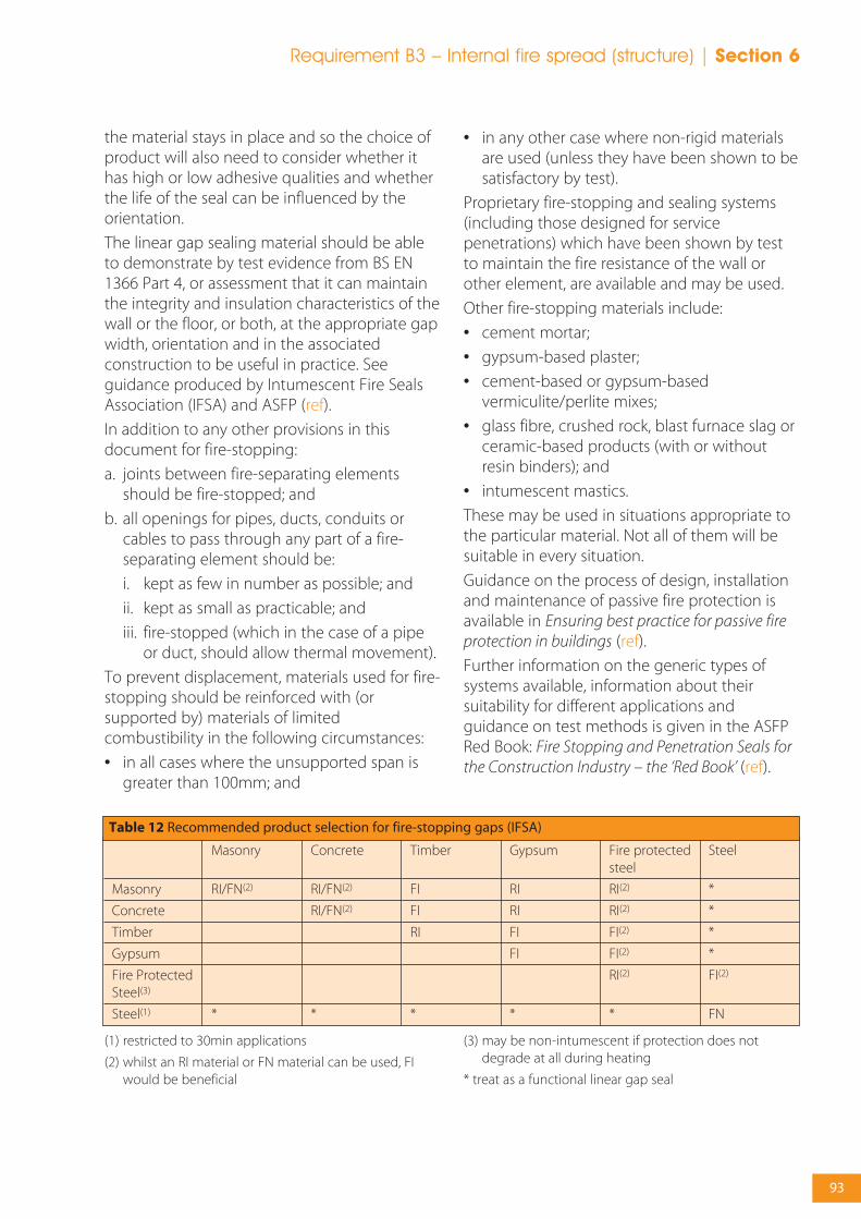
the material stays in place and so the choice ofproduct will also need to consider whether ithas high or low adhesive qualities and whetherthe life of the seal can be influenced by theorientation.
The linear gap sealing material should be ableto demonstrate by test evidence from BS EN1366 Part 4, or assessment that it can maintainthe integrity and insulation characteristics of thewall or the floor, or both, at the appropriate gapwidth, orientation and in the associatedconstruction to be useful in practice. Seeguidance produced by Intumescent Fire SealsAssociation (IFSA) and ASFP (ref).
In addition to any other provisions in thisdocument for fire-stopping:
a. joints between fire-separating elementsshould be fire-stopped; and
b. all openings for pipes, ducts, conduits orcables to pass through any part of a fire-separating element should be:
i. kept as few in number as possible; and
ii. kept as small as practicable; and
iii. fire-stopped (which in the case of a pipeor duct, should allow thermal movement).
To prevent displacement, materials used for fire-stopping should be reinforced with (orsupported by) materials of limitedcombustibility in the following circumstances:
• in all cases where the unsupported span isgreater than 100mm; and
• in any other case where non-rigid materialsare used (unless they have been shown to besatisfactory by test).
Proprietary fire-stopping and sealing systems(including those designed for servicepenetrations) which have been shown by testto maintain the fire resistance of the wall orother element, are available and may be used.
Other fire-stopping materials include:
• cement mortar;
• gypsum-based plaster;
• cement-based or gypsum-basedvermiculite/perlite mixes;
• glass fibre, crushed rock, blast furnace slag orceramic-based products (with or withoutresin binders); and
• intumescent mastics.
These may be used in situations appropriate tothe particular material. Not all of them will besuitable in every situation.
Guidance on the process of design, installationand maintenance of passive fire protection isavailable in Ensuring best practice for passive fireprotection in buildings (ref).
Further information on the generic types ofsystems available, information about theirsuitability for different applications andguidance on test methods is given in the ASFPRed Book: Fire Stopping and Penetration Seals forthe Construction Industry – the ‘Red Book’ (ref).
Masonry
Concrete
Timber
Gypsum
Fire ProtectedSteel(3)
Steel(1)
Gypsum
RI
RI
FI
FI
*
Masonry
RI/FN(2)
*
Concrete
RI/FN(2)
RI/FN(2)
*
Timber
FI
FI
RI
*
Fire protectedsteel
RI(2)
RI(2)
FI(2)
FI(2)
RI(2)
*
Steel
*
*
*
*
FI(2)
FN
Table 12 Recommended product selection for fire-stopping gaps (IFSA)
(1) restricted to 30min applications
(2) whilst an RI material or FN material can be used, FIwould be beneficial
(3) may be non-intumescent if protection does notdegrade at all during heating
* treat as a functional linear gap seal
Requirement B3 – Internal fire spread (structure) | Section 6
93
Section 7External fire spread

95
Requirement B4 – External fire spread | Section 7
7.1 Overview
7.1.1 Requirement B4 of the BuildingRegulations
(1) The external walls of the building shalladequately resist the spread of fire over thewalls and from one building to another,having regard to the height, use andposition of the building.
(2) The roof of the building shall adequatelyresist the spread of fire over the roof andfrom one building to another, having regardto the use and position of the building.
7.1.2 Performance
The Requirements of B4 will be met:
a. if the external walls are constructed so thatthe risk of ignition from an external sourceand the spread of fire over their surfaces, isrestricted, by making provision for them tohave low rates of heat release;
b. if the amount of unprotected area in the sideof the building is restricted so as to limit theamount of thermal radiation that can passthrough the wall, taking the distancebetween the wall and the boundary intoaccount; and
c. if the roof is constructed so that the risk ofspread of flame and/or fire penetration froman external fire source is restricted.
In each case so as to limit the risk of a firespreading from the building to a buildingbeyond the boundary, or vice versa.
The extent to which this is necessary isdependent on the use of the building, itsdistance from the boundary and, in some cases,its height, and the provision of fire suppressionsystems.
However, designers need to take account of thepossibility that an external fire which penetratesthe building may cause many sprinkler heads toactivate, which could rapidly exhaust the watersupply (sprinkler systems are normally designedto control fires originating from withinbuildings, when the activation of between 1~4heads is usually sufficient to do the job).
7.1.3 Introduction
7.1.3.1 External walls
The construction of external walls and theseparation between buildings to preventexternal fire spread are closely related.
The chances of fire spreading across an openspace between buildings and theconsequences if it does, depend on:
• the size and intensity of the fire in thebuilding concerned;
• the distance between the buildings;
• the fire protection given by their facing sides;and
• the risk presented to people in the otherbuilding(s).
The risk of fire transfer in the same building bythe recognised mechanism of break outfollowed by break in via adjacent or upperwindows should also be considered. Firemovement in this way can be minimised by theuse of fire-resisting glazing systems in theexternal wall.
Provisions are made in section 7.2 for the fireresistance of external walls and to limit thesusceptibility of the external surface of walls toignition and to fire spread.
Provisions are made in section 7.3 to limit theextent of openings and other unprotected areasin external walls in order to reduce the risk offire spread by radiation. This need not be thecase, however, if insulating fire-resisting glass isused. For example, 30 minute integrity glasstypes are available which can be classified for 15 minutes insulation performance. The use ofsuch glass types can widen the design optionswhilst maintaining natural lighting levelsthrough maximum glazed areas.
7.1.3.2 Roofs
Provisions are made in section 7.4 for reducingthe risk of fire spread between roofs and overthe surfaces of roofs.

96
Section 7 | Requirement B4 – External fire spread
7.2 Construction of external walls
7.2.1 Introduction
Provisions are made in this section for theexternal walls of the building to have sufficientfire resistance to prevent fire spread across therelevant boundary. The provisions are closelylinked with those for space separation in section7.3 which sets out limits on the amount ofunprotected area of wall. As the limits dependon the distance of the wall from the relevantboundary, it is possible for some or all of thewalls to have no fire resistance, except for anyparts which are load-bearing (see section6.1.3.1).
External walls are elements of structure and therelevant period of fire resistance (specified inappendix A) depends on the use, height andsize of the building concerned. If the wall is1000mm or more from the relevant boundary, areduced standard of fire resistance is acceptedin most cases and the wall only needs fireresistance from the inside.
Provisions are also made to restrict thecombustibility of external walls of schools. Thisis in order to reduce the surface’s susceptibilityto ignition from an external source and toreduce the danger from fire spread up theexternal face of the building.
In the guidance to Requirement B3, provisionsare made in section 6.2 for internal and externalload-bearing walls to maintain their load-bearing function in the event of fire.
7.2.2 Fire resistance standard
The external walls of the building should havethe appropriate fire resistance given inappendix A, table A1, unless they form anunprotected area under the provisions ofsection 7.3.
7.2.3 External wall construction
The external envelope of a building should notprovide a medium for fire spread if it is likely tobe a risk to health or safety. The use ofcombustible materials in the cladding systemand extensive cavities may present such a risk intall buildings.
External walls should either meet the guidancegiven in section 7.2.4 and 7.2.4.1 or meet theperformance criteria given in the BRE Report Fireperformance of external thermal insulation forwalls of multi storey buildings (BR 135) forcladding systems using full scale test data fromBS 8414-1:2002 or BS 8414-2:2005.
The total amount of combustible material mayalso be limited in practice by the provisions forspace separation in section 7.3 (see section 7.3.3onwards).
7.2.4 External surfaces
The external surfaces of walls should meet theprovisions in table 13.
To reduce the risk of external fires damagingthe structure, combustible cladding for theground floor level should only be used as partof a fire engineering solution.
Distance from relevant boundary
Less than 1000mm
1000mm or more
1000mm or more
Height of wall
Any
Single storey
More than one storey:a) up to 10m above groundb) up to 10m above a roof or anypart of the building to which pupilsor the public have access
External wall surface classification
Class 0 (national standards) or classB-s3,d2 or better (European class).Profiled or flat steel sheet at least0.5mm thick with an organic coatingof no more than 0.2mm thickness isalso acceptable
No requirement
Index (I) not more than 20 (nationalclass) or class C-s3,d2 or better(European class). Timber cladding atleast 9mm thick is also acceptable.(The index I relates to tests specifiedin BS 476-6)
Table 13 Provisions for external surfaces or walls

97
Requirement B4 – External fire spread | Section 7
7.2.4.1 Cavity barriers
Cavity barriers should be provided in accordancewith section 6.4.
In the case of an external wall construction, of abuilding which, by virtue of section 6.4.4.1(external cladding system with a masonry orconcrete inner leaf), is not subject to theprovisions of table 10 (maximum dimensions ofcavities), the surfaces which face into cavitiesshould also meet the provisions of table 13.
7.3 Space separation
7.3.1 Introduction
The provisions in this section are based on anumber of assumptions and, whilst some ofthese may differ from the circumstances of aparticular case, together they enable areasonable standard of space separation to bespecified. The provisions limit the extent ofunprotected areas in the sides of a building(such as openings and areas with a combustiblesurface) which will not give adequate protectionagainst the external spread of fire from onebuilding to another.
A roof is not subject to the provisions in thissection unless it is pitched at an angle greaterthan 70º to the horizontal (see definition for‘external wall’ in appendix F). Similarly, verticalparts of a pitched roof such as dormer windows(which taken in isolation might be regarded as awall), would not need to meet the followingprovisions unless the slope of the roof exceeds70º. It is a matter of judgement whether acontinuous run of dormer windows occupyingmost of a steeply pitched roof should be treatedas a wall rather than a roof.
The assumptions are:
a. that the size of a fire will depend on thecompartmentation of the building, so that afire may involve a complete compartment,but will not spread to other compartments;
b. that the intensity of the fire is related to theuse of the building (ie, purpose group), butthat it can be moderated by a sprinkler system;
c. that there is a building on the far side of theboundary that has a similar elevation to theone in question and that it is at the samedistance from the common boundary; and
d. that the amount of radiation passing throughany part of the external wall that has fireresistance be discounted provided that whereglazing is concerned the fire-resisting glasshas a measure of insulation performance forat least 15 minutes.
Where a reduced separation distance is desired(or an increased amount of unprotected area) itmay be advantageous to constructcompartments of a smaller size.
7.3.2 Boundaries
The use of the distance to a boundary, ratherthan to another building, in measuring theseparation distance, makes it possible tocalculate the allowable proportion ofunprotected areas, regardless of whether thereis a building on an adjoining site and regardlessof the site of that building or the extent of anyunprotected areas that it might have.
A wall is treated as facing a boundary if it makesan angle with it of 80º or less (see figure 37).
Usually only the distance to the actual boundaryof the site needs to be considered. But in somecircumstances, when the site boundary adjoins aspace where further development is unlikely,such as a road, then part of the adjoining spacemay be included as falling within the relevantboundary for the purposes of this section. Themeaning of the term boundary is explained infigure 37.
For property protection, the distance to notionalboundaries (see section 7.3.2.2) between schoolbuildings on the same site should be considered.
7.3.2.1 Relevant boundaries
The boundary which a wall faces, whether it isthe actual boundary of the site or a notionalboundary, is called the relevant boundary (seefigures 37 and 38).
7.3.2.2 Notional boundaries
Notional boundaries are assumed to existbetween different buildings on the same site.
The separation between buildings on the samesite is normally only recommended for thepurposes of property protection.

98
Section 7 | Requirement B4 – External fire spread
However, if one of the buildings is residential, orwhere buildings on the site areoperated/managed by different organisations,then separation is required to satisfy theBuilding Regulations with respect to life safety.
The appropriate rules are given in figure 38.
7.3.3 Unprotected areas and fireresistance
Any part of an external wall which has less fireresistance than the appropriate amount givenin appendix A, table A2, is considered to be anunprotected area.
7.3.3.1 External walls of protected shaftsforming stairways
Any part of an external wall of a stairway in aprotected shaft is excluded from theassessment of unprotected area.
Note: There are provisions in the guidance toB1 (section 4.4.6.7, figure 22) which refers tosection 2 of BS 5588-5:2004 about therelationship of external walls for protectedstairways to the unprotected areas of otherparts of the building.
Figure 37 Relevant boundary
This diagram sets out the rules that apply in respect of aboundary for it to be considered as a relevant boundary.
For a boundary to be relevant it should:a. coincide with; orb. be parallel to; or c. be at an angle of not more than 80° to the side of thebuilding.
See sections 7.3.2.1 and 7.3.2.2
Figure 38 Notional boundary
See section 7.3.2.2
The notional boundary should be set in the area between two buildings using the following rules:
1. The notional boundary is assumed to exist in the space between the buildings and is positioned so that one of the buildings wouldcomply with the provisions of space separation having regard to the amount of its unprotected area. In practice, if one of the buildingsis existing, the position of the boundary will be set by the space separation factors for that building.
2. The siting of the new building, or the second building if both are new, can then be checked to see that it also complies, using thenotional boundary as the relevant boundary for the second building.

99
Requirement B4 – External fire spread | Section 7
7.3.3.2 Status of combustible surfacematerials as unprotected area
If an external wall has the appropriate fireresistance, but has combustible material morethan 1mm thick as its external surface, then thatwall is counted as an unprotected areaamounting to half the actual area of thecombustible material, see figure 39. (For the
purposes of this provision, a material with aClass 0 rating (National class) or Class B-s3, d2rating (European class) (see appendix A) neednot be counted as unprotected area).
Note: When a classification includes ‘s3, d2’, thismeans that there is no limit set for smokeproduction and/or flaming droplets/particles.
7.3.3.3 Small unprotected areas
Small unprotected areas in an otherwiseprotected area of wall are considered to pose anegligible risk of fire spread and may bedisregarded. Figure 40 shows the constraintsthat apply to the placing of such areas inrelation to each other and to lines ofcompartmentation inside the building. Theseconstraints vary according to the size of eachunprotected area.
7.3.3.4 Canopies
Some canopy structures would be exempt fromthe application of the Building Regulations byfalling within Class VI or Class VII of Schedule 2to the Regulations (Exempt buildings andworks). Many others may not meet theexemption criteria and in such cases theprovisions in this section about limits ofunprotected areas could be onerous.
Figure 39 Status of combustible surface material asunprotected areaSee section 7.3.3.2
Figure 40 Unprotected areas which may be disregarded in assessing the separation distance from the boundry
See section 7.3.3.3
Key:
or Represents an unprotectedarea of not more than 1m2 which mayconsist of two or more smaller areaswithin an area of 1000x1000mm
Represents an area of not more than0.1m2
Dimensional restrictions:
4m minimum distance
1500mm minimum distance
Dimension unrestricted
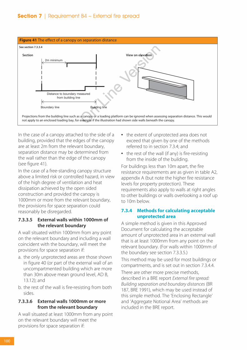
100
Section 7 | Requirement B4 – External fire spread
In the case of a canopy attached to the side of abuilding, provided that the edges of the canopyare at least 2m from the relevant boundary,separation distance may be determined fromthe wall rather than the edge of the canopy(see figure 41).
In the case of a free-standing canopy structureabove a limited risk or controlled hazard, in viewof the high degree of ventilation and heatdissipation achieved by the open sidedconstruction and provided the canopy is1000mm or more from the relevant boundary,the provisions for space separation couldreasonably be disregarded.
7.3.3.5 External walls within 1000mm ofthe relevant boundary
A wall situated within 1000mm from any pointon the relevant boundary and including a wallcoincident with the boundary, will meet theprovisions for space separation if:
a. the only unprotected areas are those shownin figure 40 (or part of the external wall of anuncompartmented building which are morethan 30m above mean ground level, AD B,13.12); and
b. the rest of the wall is fire-resisting from bothsides.
7.3.3.6 External walls 1000mm or morefrom the relevant boundary
A wall situated at least 1000mm from any pointon the relevant boundary will meet theprovisions for space separation if:
• the extent of unprotected area does notexceed that given by one of the methodsreferred to in section 7.3.4; and
• the rest of the wall (if any) is fire-resistingfrom the inside of the building.
For buildings less than 10m apart, the fireresistance requirements are as given in table A2,appendix A (but note the higher fire resistancelevels for property protection). Theserequirements also apply to walls at right anglesto other buildings or walls overlooking a roof upto 10m below.
7.3.4 Methods for calculating acceptableunprotected area
A simple method is given in this ApprovedDocument for calculating the acceptableamount of unprotected area in an external wallthat is at least 1000mm from any point on therelevant boundary. (For walls within 1000mm ofthe boundary see section 7.3.3.5.)
This method may be used for most buildings orcompartments, and is set out in section 7.3.4.4.
There are other more precise methods,described in a BRE report External fire spread:Building separation and boundary distances (BR187, BRE 1991), which may be used instead ofthis simple method. The ‘Enclosing Rectangle’and ‘Aggregate Notional Area’ methods areincluded in the BRE report.
Figure 41 The effect of a canopy on separation distance
See section 7.3.3.4
Projections from the building line such as a canopy or a loading platform can be ignored when assessing separation distance. This wouldnot apply to an enclosed loading bay, for example if the illustration had shown side walls beneath the canopy.
Section View on elevation
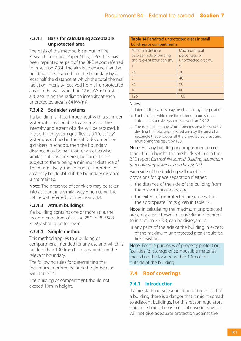
101
Requirement B4 – External fire spread | Section 7
7.3.4.1 Basis for calculating acceptableunprotected area
The basis of the method is set out in FireResearch Technical Paper No 5, 1963. This hasbeen reprinted as part of the BRE report referredto in section 7.3.4. The aim is to ensure that thebuilding is separated from the boundary by atleast half the distance at which the total thermalradiation intensity received from all unprotectedareas in the wall would be 12.6 kW/m2 (in stillair), assuming the radiation intensity at eachunprotected area is 84 kW/m2.
7.3.4.2 Sprinkler systems
If a building is fitted throughout with a sprinklersystem, it is reasonable to assume that theintensity and extent of a fire will be reduced. Ifthe sprinkler system qualifies as a ‘life safety’system, as defined in the SSLD document onsprinklers in schools, then the boundarydistance may be half that for an otherwisesimilar, but unsprinklered, building. This issubject to there being a minimum distance of1m. Alternatively, the amount of unprotectedarea may be doubled if the boundary distanceis maintained.
Note: The presence of sprinklers may be takeninto account in a similar way when using theBRE report referred to in section 7.3.4.
7.3.4.3 Atrium buildings
If a building contains one or more atria, therecommendations of clause 28.2 in BS 5588-7:1997 should be followed.
7.3.4.4 Simple method
This method applies to a building orcompartment intended for any use and which isnot less than 1000mm from any point on therelevant boundary.
The following rules for determining themaximum unprotected area should be readwith table 14.
The building or compartment should notexceed 10m in height.
Notes:
a. Intermediate values may be obtained by interpolation.
b. For buildings which are fitted throughout with anautomatic sprinkler system, see section 7.3.4.2.
c. The total percentage of unprotected area is found bydividing the total unprotected area by the area of arectangle that encloses all the unprotected areas andmultiplying the result by 100.
Note: For any building or compartment morethan 10m in height, the methods set out in theBRE report External fire spread: Building separationand boundary distances can be applied.
Each side of the building will meet theprovisions for space separation if either:
i. the distance of the side of the building fromthe relevant boundary; and
ii. the extent of unprotected area, are withinthe appropriate limits given in table 14.
Note: In calculating the maximum unprotectedarea, any areas shown in figure 40 and referredto in section 7.3.3.3, can be disregarded.
iii. any parts of the side of the building in excessof the maximum unprotected area should befire-resisting.
Note: For the purposes of property protection,facilities for storage of combustible materialsshould not be located within 10m of theoutside of the building
7.4 Roof coverings
7.4.1 Introduction
If a fire starts outside a building or breaks out ofa building there is a danger that it might spreadto adjacent buildings. For this reason regulatoryguidance limits the use of roof coverings whichwill not give adequate protection against the
Minimum distancebetween side of buildingand relevant boundary (m)
1
2.5
5
7.5
10
12.5
Maximum totalpercentage ofunprotected area (%)
8
20
40
60
80
100
Table 14 Permitted unprotected areas in smallbuildings or compartments

102
Section 7 | Requirement B4 – External fire spread
spread of fire over them near a boundary (seetable A5 and appendix A).
The term roof covering is used to describeconstructions which may consist of one or morelayers of material, but does not refer to the roofstructure as a whole. The provisions in thissection are principally concerned with theperformance of roofs when exposed to fire fromthe outside.
The circumstances when a roof is subject to theprovisions in section 7.3 for space separation areexplained in section 7.3.1.
7.4.1.1 Other controls on roofs
There are provisions concerning the fireproperties of roofs in three other sections of thisdocument. In the guidance to B1 (section4.5.2.1) there are provisions for roofs that arepart of a means of escape. In the guidance to B2(section 5.2.3.3) there are provisions for theinternal surfaces of rooflights as part of theinternal lining of a room or circulation space. Inthe guidance to B3 there are provisions insection 6.2.2.2 for roofs which are used as a floorand in section 6.3.3.6 for roofs that pass over thetop of a compartment wall.
7.4.2 Classification of performance
The performance of roof coverings isdesignated by reference to the test methodsspecified in BS 476-3: 2004 or determined inaccordance with BS EN 13501-5:2005, asdescribed in appendix A. The notionalperformance of some common roof coverings isgiven in table A5 of appendix A.
Rooflights are controlled on a similar basis andplastic rooflights described in section 7.4.2.2may also be used.
7.4.2.1 Separation distances
The separation distance is the minimumdistance from the roof (or part of the roof) tothe relevant boundary, which may be a notionalboundary.
Table 15 sets out separation distancesaccording to the type of roof covering and thesize and use of the building. There are norestrictions on the use of roof coveringsdesignated AA, AB or AC (National class) orBROOF(t4) (European class) classification. Inaddition, roof covering products (and/ormaterials) as defined in Commission Decision2000/553/EC of 6th September 2000implementing Council Directive 89/106/EEC as
National Class
AA, AB or AC
BA, BB or BC
CA, CB or CC
AD, BD or CD
DA, DB, DC orDD
At least 12m
✓
✓
✓ (1)
✓ (1)
✗
European Class
BROOF(t4)
CROOF(t4)
DROOF(t4)
EROOF(t4)
FROOF(t4)
Less than 6m
✓
✗
✗
✗
✗
At least 6m
✓
✓
✓ (1)(2)
✓
✗
At least 20m
✓
✓
✓
✓
✓ (1)(2)
Table 15 Limitations on roof coverings*
Designation† of covering of roof orpart of roof
Minimum distance from any point on relevant boundary
Notes:
* See section 7.4.2.3 for limitations on glass, section7.4.2.4 for limitations on thatch and wood shingles;and section 7.4.2.2 and tables 16 and 17 for limitationson plastic rooflights.
† The designation of external roof surfaces is explainedin appendix A. (See table A5, for notional designationsof roof coverings.)
Openable polycarbonate and PVC rooflights whichachieve a Class 1 (National class) or Class C-s3, d2(European class) rating by test, see section 7.4.2.2, may beregarded as having an AA (National class) designation orBROOF(t4) (European class) classification.
✔ Acceptable.✗ Not acceptable.
1. Not acceptable on any buildings with a cubic capacityof more than 1500m3.
2. Acceptable on buildings not listed in Note 1, if part ofthe roof is no more than 3m2 in area and is at least1500mm from any similar part, with the roof betweenthe parts covered with a material of limitedcombustibility.
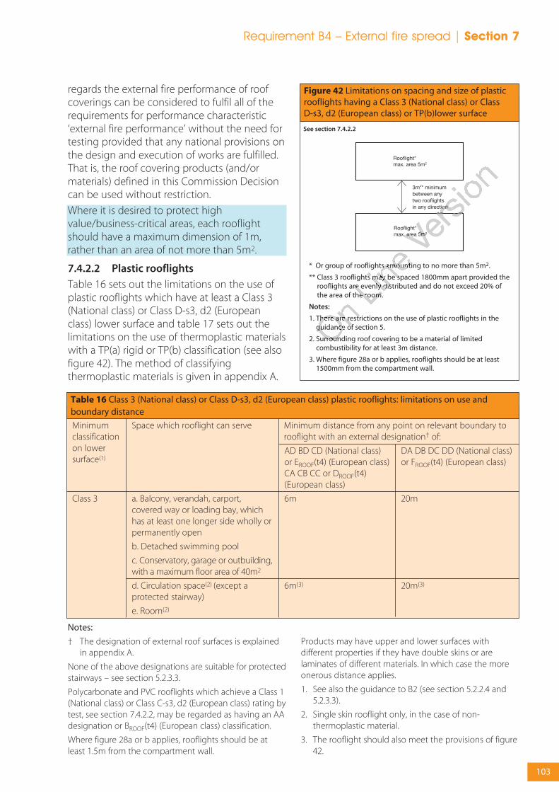
103
Requirement B4 – External fire spread | Section 7
Notes:
† The designation of external roof surfaces is explainedin appendix A.
None of the above designations are suitable for protectedstairways – see section 5.2.3.3.
Polycarbonate and PVC rooflights which achieve a Class 1(National class) or Class C-s3, d2 (European class) rating bytest, see section 7.4.2.2, may be regarded as having an AAdesignation or BROOF(t4) (European class) classification.
Where figure 28a or b applies, rooflights should be atleast 1.5m from the compartment wall.
Products may have upper and lower surfaces withdifferent properties if they have double skins or arelaminates of different materials. In which case the moreonerous distance applies.
1. See also the guidance to B2 (see section 5.2.2.4 and5.2.3.3).
2. Single skin rooflight only, in the case of non-thermoplastic material.
3. The rooflight should also meet the provisions of figure42.
DA DB DC DD (National class)or FROOF(t4) (European class)
20m
20m(3)
Minimumclassificationon lowersurface(1)
Class 3
Space which rooflight can serve
a. Balcony, verandah, carport,covered way or loading bay, whichhas at least one longer side wholly orpermanently open
b. Detached swimming pool
c. Conservatory, garage or outbuilding,with a maximum floor area of 40m2
d. Circulation space(2) (except aprotected stairway)
e. Room(2)
AD BD CD (National class)or EROOF(t4) (European class)CA CB CC or DROOF(t4)(European class)
6m
6m(3)
Table 16 Class 3 (National class) or Class D-s3, d2 (European class) plastic rooflights: limitations on use andboundary distance
Minimum distance from any point on relevant boundary torooflight with an external designation† of:
regards the external fire performance of roofcoverings can be considered to fulfil all of therequirements for performance characteristic‘external fire performance’ without the need fortesting provided that any national provisions onthe design and execution of works are fulfilled.That is, the roof covering products (and/ormaterials) defined in this Commission Decisioncan be used without restriction.
Where it is desired to protect highvalue/business-critical areas, each rooflightshould have a maximum dimension of 1m,rather than an area of not more than 5m2.
7.4.2.2 Plastic rooflights
Table 16 sets out the limitations on the use ofplastic rooflights which have at least a Class 3(National class) or Class D-s3, d2 (Europeanclass) lower surface and table 17 sets out thelimitations on the use of thermoplastic materialswith a TP(a) rigid or TP(b) classification (see alsofigure 42). The method of classifyingthermoplastic materials is given in appendix A.
3m** minimumbetween any two rooflightsin any direction
Figure 42 Limitations on spacing and size of plasticrooflights having a Class 3 (National class) or Class D-s3, d2 (European class) or TP(b)lower surface
See section 7.4.2.2
* Or group of rooflights amounting to no more than 5m2.
** Class 3 rooflights may be spaced 1800mm apart provided therooflights are evenly distributed and do not exceed 20% ofthe area of the room.
Notes:
1. There are restrictions on the use of plastic rooflights in theguidance of section 5.
2. Surrounding roof covering to be a material of limitedcombustibility for at least 3m distance.
3. Where figure 28a or b applies, rooflights should be at least1500mm from the compartment wall.
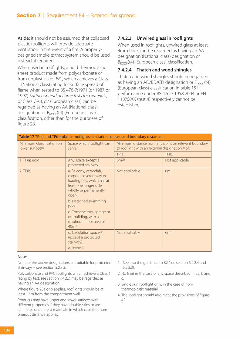
104
Section 7 | Requirement B4 – External fire spread
Aside: it should not be assumed that collapsedplastic rooflights will provide adequateventilation in the event of a fire. A properly-designed smoke extract system should be usedinstead, if required.
When used in rooflights, a rigid thermoplasticsheet product made from polycarbonate orfrom unplasticised PVC, which achieves a Class1 (National class) rating for surface spread offlame when tested to BS 476-7:1971 (or 1987 or1997) Surface spread of flame tests for materials,or Class C-s3, d2 (European class) can beregarded as having an AA (National class)designation or BROOF(t4) (European class)classification, other than for the purposes offigure 28.
7.4.2.3 Unwired glass in rooflights
When used in rooflights, unwired glass at least4mm thick can be regarded as having an AAdesignation (National class) designation orBROOF(t4) (European class) classification.
7.4.2.4 Thatch and wood shingles
Thatch and wood shingles should be regardedas having an AD/BD/CD designation or EROOF(t4)(European class) classification in table 15 ifperformance under BS 476-3:1958 2004 or EN1187:XXX (test 4) respectively cannot beestablished.
TP(b)
Not applicable
6m
6m(4)
Minimum classification onlower surface(1)
1. TP(a) rigid
2. TP(b)
Space which rooflight canserve
Any space except aprotected stairway
a. Balcony, verandah,carport, covered way orloading bay, which has atleast one longer sidewholly or permanentlyopen
b. Detached swimmingpool
c. Conservatory, garage oroutbuilding, with amaximum floor area of40m2
d. Circulation space(3)
(except a protectedstairway)
e. Room(3)
TP(a)
6m(2)
Not applicable
Not applicable
Table 17 TP(a) and TP(b) plastic rooflights: limitations on use and boundary distance
Minimum distance from any point on relevant boundaryto rooflight with an external designation(1) of:
Notes:
None of the above designations are suitable for protectedstairways – see section 5.2.3.3.
Polycarbonate and PVC rooflights which achieve a Class 1rating by test, see section 7.4.2.2, may be regarded ashaving an AA designation.
Where figure 28a or b applies, rooflights should be atleast 1.5m from the compartment wall.
Products may have upper and lower surfaces withdifferent properties if they have double skins or arelaminates of different materials; in which case the moreonerous distance applies.
1. See also the guidance to B2 (see section 5.2.2.4 and5.2.3.3).
2. No limit in the case of any space described in 2a, b andc.
3. Single skin rooflight only, in the case of non-thermoplastic material.
4. The rooflight should also meet the provisions of figure42.
Section 8Access and facilitiesfor the Fire and RescueService

8.1 Overview
8.1.1 Requirement B5 of the BuildingRegulations
(1) The building shall be designed andconstructed so as to provide reasonablefacilities to assist firefighters in the protectionof life.
(2) Reasonable provision shall be made withinthe site of the building to enable fireappliances to gain access to the building.
8.1.2 Performance
The Requirements of B5 will be met:
a. if there is sufficient means of external accessto enable fire appliances to be brought nearto the building for effective use;
b. if there is sufficient means of access into andwithin, the building for fire-fightingpersonnel to effect search and rescue andfight fire;
c. if the building is provided with sufficientinternal fire mains and other facilities to assistfire-fighters in their tasks; and
d. if the building is provided with adequatemeans for venting heat and smoke from afire in a basement.
These access arrangements and facilities areonly required in the interests of the health andsafety of people in and around the building. Theextent to which they are required will dependon the use and size of the building in so far as itaffects the health and safety of those people.
8.1.3 Introduction
The guidance given here covers the selectionand design of facilities for the purpose ofprotecting life by assisting the Fire and RescueService. To assist the Fire and Rescue Servicesome or all of the following facilities may benecessary, depending mainly on the size of thebuilding:
• vehicle access for fire appliances;
• access for fire-fighting personnel;
• the provision of fire mains within the building;
• venting for heat and smoke from basementareas; and
• the provision of adequate water supplies.
If it is proposed to deviate from the generalguidance in sections 8.2 – 8.5 then it would beadvisable to seek advice from the relevant Fireand Rescue Service at the earliest opportunity,even where there is no statutory duty to consult.
8.1.3.1 Facilities appropriate to a specificbuilding
The main factor determining the facilitiesneeded to assist the Fire and Rescue Service isthe size of the building. Generally speaking fire-fighting is carried out within the building.
They need special access facilities (see section8.4), equipped with fire mains (see section 8.2).Fire appliances will need access to entry pointsnear the fire mains (see section 8.3).
In most buildings, the combination of personnelaccess facilities offered by the normal means ofescape and the ability to work from ladders andappliances on the perimeter, will generally beadequate without special internalarrangements. Vehicle access may be needed tosome or all of the perimeter, depending on thesize of the building (see section 8.2).
Note: Where an alternative approach outside thescope of this document has been used to justifythe means of escape it may be necessary toconsider additional provisions for fire-fightingaccess.
For small buildings, it is usually only necessaryto ensure that the building is sufficiently closeto a point accessible to Fire and Rescue Servicevehicles (see section 8.3.2).
Products of combustion from basement firestend to escape via stairways, making accessdifficult for Fire and Rescue Service personnel.The problem can be reduced by providingvents (see section 8.4). Venting can improvevisibility and reduce temperatures, makingsearch, rescue and fire-fighting less difficult.
8.1.3.2 Insulating core panels
Guidance on the fire behaviour of insulatingcore panels used for internal structures is givenin appendix B.
Section 8 | Requirement B5 – Access and facilities for the Fire and Rescue Service
106

8.2 Fire mains and hydrants
8.2.1 Introduction
Fire mains are installed in a building andequipped with valves, etc, so that the Fire andRescue Service may connect hoses for water tofight fires inside the building.
Fire mains may be of the ‘dry’ type which arenormally empty and are supplied through ahose from a Fire and Rescue Service pumpingappliance. Alternatively, they may be of the‘wet’ type where they are kept full of water andsupplied from tanks and pumps in the building.There should be a facility to allow a wet systemto be replenished from a pumping appliance inan emergency.
8.2.2 Fire mains in buildings with fire-fighting shafts
Buildings with fire-fighting shafts should beprovided with fire mains in those shafts and,where necessary, in protected escape stairs. Thecriteria for the provision of fire-fighting shaftsand fire mains in such buildings are given insection 8.4.
8.2.2.1 Fire mains in other buildings
Fire mains may also be provided in otherbuildings where vehicle access is not providedin accordance with table 18 (see section 8.3.3)or section 8.3.2.
8.2.3 Number and location of fire mains
In buildings provided with fire mains for thepurposes of section 8.2.2.1, outlets from firemains should be located to meet the hosecriterion set out in section 8.4.3. This does notimply that these stairs need to be designed asfire-fighting shafts.
8.2.4 Design and construction of firemains
The outlets from fire mains should be locatedwithin the protected enclosure of a stairway ora protected lobby where one is provided (seefigure 46).
Guidance on other aspects of the design andconstruction of fire mains, not included in theprovisions of this document, should beobtained from BS 9990:2006.
8.2.5 Provision of private hydrants
Where a building, which has a compartment of280m2 or more in area, is being erected morethan 100m from an existing fire-hydrantadditional hydrants should be provided asfollows;
• Buildings provided with fire mains –hydrants should be provided within 90m ofdry fire main inlets.
• Buildings not provided with fire mains –hydrants should be provided within 90m ofan entry point to the building and not morethan 90m apart.
Each fire hydrant should be clearly indicated bya plate, affixed nearby in a conspicuousposition, in accordance with BS 3251:1976.
Where no piped water supply is available, orthere is insufficient pressure and flow in thewater main, or an alternative arrangement isproposed, the alternative source of supplyshould be provided in accordance with thefollowing recommendations:
a. a charged static water tank of at least 45,000litre capacity; or
b. a spring, river, canal or pond capable ofproviding or storing at least 45,000 litres ofwater at all times of the year, to which access,space and a hard standing are available for apumping appliance; or
c. any other means of providing a water supplyfor fire-fighting operations consideredappropriate by the Fire and Rescue Authority.
8.3 Vehicle access
8.3.1 Introduction
For the purposes of this document vehicleaccess to the exterior of a building is needed toenable high reach appliances, such as turntableladders and hydraulic platforms, to be used andto enable pumping appliances to supply waterand equipment for fire-fighting, search andrescue activities.
Access requirements increase with building sizeand height.
Fire mains (see section 8.2) enable fire-fighterswithin the building to connect their hoses to a
Requirement B5 – Access and facilities for the Fire and Rescue Service | Section 8
107
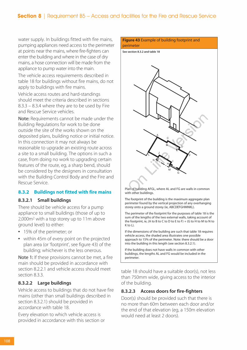
water supply. In buildings fitted with fire mains,pumping appliances need access to the perimeterat points near the mains, where fire-fighters canenter the building and where in the case of drymains, a hose connection will be made from theappliance to pump water into the main.
The vehicle access requirements described intable 18 for buildings without fire mains, do notapply to buildings with fire mains.
Vehicle access routes and hard-standingsshould meet the criteria described in sections8.3.3 – 8.3.4 where they are to be used by Fireand Rescue Service vehicles.
Note: Requirements cannot be made under theBuilding Regulations for work to be doneoutside the site of the works shown on thedeposited plans, building notice or initial notice.In this connection it may not always bereasonable to upgrade an existing route acrossa site to a small building. The options in such acase, from doing no work to upgrading certainfeatures of the route, eg, a sharp bend, shouldbe considered by the designers in consultationwith the Building Control Body and the Fire andRescue Service.
8.3.2 Buildings not fitted with fire mains
8.3.2.1 Small buildings
There should be vehicle access for a pumpappliance to small buildings (those of up to2,000m2 with a top storey up to 11m aboveground level) to either:
• 15% of the perimeter; or
• within 45m of every point on the projectedplan area (or ‘footprint’, see figure 43) of thebuilding; whichever is the less onerous.
Note 1: If these provisions cannot be met, a firemain should be provided in accordance withsection 8.2.2.1 and vehicle access should meetsection 8.3.3.
8.3.2.2 Large buildings
Vehicle access to buildings that do not have firemains (other than small buildings described insection 8.3.2.1) should be provided inaccordance with table 18.
Every elevation to which vehicle access isprovided in accordance with this section or
table 18 should have a suitable door(s), not lessthan 750mm wide, giving access to the interiorof the building.
8.3.2.3 Access doors for fire-fighters
Door(s) should be provided such that there isno more than 60m between each door and/orthe end of that elevation (eg, a 150m elevationwould need at least 2 doors).
Figure 43 Example of building footprint andperimeter
See section 8.3.2 and table 18
Plan of building AFGL, where AL and FG are walls in commonwith other buildings.
The footprint of the building is the maximum aggregate planperimeter found by the vertical projection of any overhangingstorey onto a ground storey (ie, ABCDEFGHMNKL).
The perimeter of the footprint for the purposes of table 18 is thesum of the lengths of the two external walls, taking account ofthe footprint, ie, (A to B to C to D to E to F) + (G to H to M to N toK to L).
If the dimensions of the building are such that table 18 requiresvehicle access, the shaded area illustrates one possibleapproach to 15% of the perimeter. Note: there should be a doorinto the building in this length (see section 8.3.2.1).
If the building does not have walls in common with otherbuildings, the lengths AL and FG would be included in theperimeter.
Section 8 | Requirement B5 – Access and facilities for the Fire and Rescue Service
108

Type of Appliance
Pump
High reach
Pump
High reach
Pump
High reach
Pump
High reach
Pump
High reach
Total floor area(1) ofbuilding m2
up to 2,000
2,000-8,000
8,000-16,000
16,000-24,000
over 24,000
Height of floor of topstorey above ground
Up to 11
Over 11
Up to 11
Over 11
Up to 11
Over 11
Up to 11
Over 11
Up to 11
Over 11
Provide vehicle access(2)(4)
to:
See Note(3)
15% of perimeter(5)
15% of perimeter(5)
50% of perimeter(5)
50% of perimeter(5)
50% of perimeter(5)
75% of perimeter(5)
75% of perimeter(5)
100% of perimeter(5)
100% of perimeter(5)
Table 18 Fire and Rescue Service vehicle access to school buildings not fitted with fire mains
Notes:
1. The total floor area is the aggregate of all floors in thebuilding (excluding basements).
2. An access door not less than 750mm wide is requiredto each elevation to which vehicle access is provided,which gives access to the interior of the building.
3. Access to be provided for a pump appliance to either(a) 15% of the perimeter, or (b) within 45m of everypoint on the projected plan area of the buildingwhichever is the less onerous.
4. See section 8.3.3 for meaning of access.
5. Perimeter is described in figure 43.
Requirement B5 – Access and facilities for the Fire and Rescue Service | Section 8
109
Appliance type
Pump
High Reach
Minimumturning circlebetween walls(m)
19.2
29.0
Minimum widthof road betweenkerbs (m)
3.7
3.7
Minimum widthof gateways (m)
3.1
3.1
Minimumturning circlebetween kerbs(m)
16.8
26.0
Minimumcarrying capacity(tonnes)
12.5
17.0
Table 19 Typical Fire and Rescue Service vehicle access route specification
Notes:
1. Fire appliances are not standardised. Some fireservices have appliances of greater weight or differentsize. In consultation with the Fire Authority, theDesigners and the Building Control Body may adoptother dimensions in such circumstances.
2. Because the weight of high reach appliances isdistributed over a number of axles, and they are onlyused occasionally they should not cause any damageto a carriageway or route designed to 12.5 tonnesrather than the full 17 tonnes capacity.
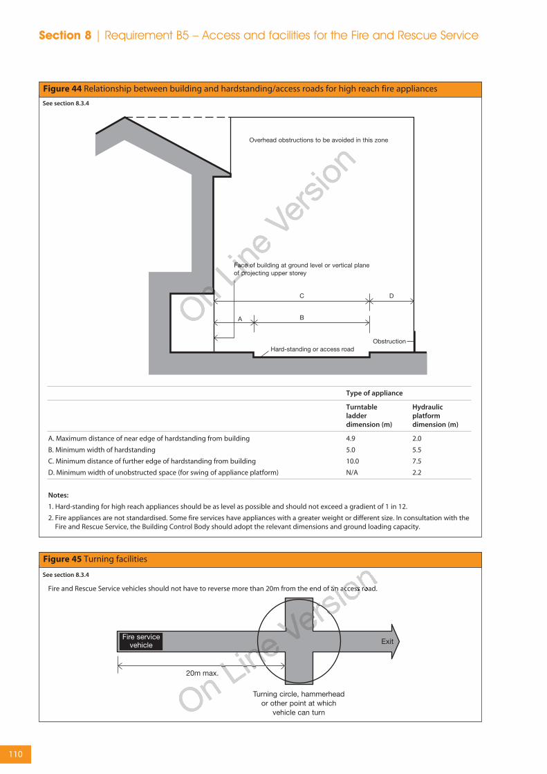
Figure 44 Relationship between building and hardstanding/access roads for high reach fire appliances
Type of appliance
Turntable Hydraulicladder platformdimension (m) dimension (m)
A. Maximum distance of near edge of hardstanding from building 4.9 2.0
B. Minimum width of hardstanding 5.0 5.5
C. Minimum distance of further edge of hardstanding from building 10.0 7.5
D. Minimum width of unobstructed space (for swing of appliance platform) N/A 2.2
Notes:
1. Hard-standing for high reach appliances should be as level as possible and should not exceed a gradient of 1 in 12.
2. Fire appliances are not standardised. Some fire services have appliances with a greater weight or different size. In consultation with theFire and Rescue Service, the Building Control Body should adopt the relevant dimensions and ground loading capacity.
See section 8.3.4
Figure 45 Turning facilities
See section 8.3.4
Fire and Rescue Service vehicles should not have to reverse more than 20m from the end of an access road.
Section 8 | Requirement B5 – Access and facilities for the Fire and Rescue Service
110

8.3.3 Buildings fitted with fire mains
In the case of a building fitted with dry firemains there should be access for a pumpingappliance to within 18m of each fire main inletconnection point, typically on the face of thebuilding. The inlet should be visible from theappliance.
In the case of a building fitted with wet mainsthe pumping appliance access should be towithin 18m and within sight of, a suitableentrance giving access to the main and in sightof the inlet for the emergency replenishment ofthe suction tank for the main.
Note: Where fire mains are provided inbuildings for which sections 8.2 and 8.4 makeno provision, vehicle access may be to thissection rather than table 18.
8.3.4 Design of access routes and hard-standings
A vehicle access route may be a road or otherroute which, including any inspection coversand the like, meets the standards in table 19and the following paragraphs.
Where access is provided to an elevation inaccordance with table 18 for:
a. buildings up to 11m in height (excludingsmall buildings covered by section 8.3.2.1),there should be access for a pump applianceadjacent to the building for the percentageof the total perimeter specified;
b. buildings over 11m in height, the accessroutes should meet the guidance in figure44.
Where access is provided to an elevation forhigh reach appliances in accordance with table18, overhead obstructions such as cables andbranches that would interfere with the settingof ladders, etc, should be avoided in the zoneshown in figure 44.
Turning facilities should be provided in anydead-end access route that is more than 20mlong (see figure 45). This can be by ahammerhead or turning circle, designed on thebasis of table 19.
8.4 Access to buildings for fire-fighting personnel
8.4.1 Introduction
In low-rise buildings without deep basementsFire and Rescue Service personnel accessrequirements will be met by a combination ofthe normal means of escape and the measuresfor vehicle access in section 8.3, which facilitateladder access to upper storeys. In otherbuildings, the problems of reaching the fire andworking inside near the fire, necessitate theprovision of additional facilities to avoid delayand to provide a sufficiently secure operatingbase to allow effective action to be taken.
These additional facilities include fire-fightinglifts, fire-fighting stairs and fire-fighting lobbies,which are combined in a protected shaft knownas the fire-fighting shaft (figure 46).
Guidance on protected shafts in general isgiven in section 6.3.
Fire main outlet
Figure 46 Components of a fire-fighting shaft
Notes:
1. Outlets from a fire main should be located in the fire-fightinglobby.
2. Smoke control should be provided in accordance with BS5588-5:2004.
3. A fire-fighting lift is required if the building has a floor morethat 18m above or 10m below, fire service vehicle access level.
4. This figure is only to illustrate the basic components and is notmeant to represent the only acceptable layout. The shaftshould be constructed generally in accordance with clauses 7and 8 of BS 5588-5:2004.
See section 8.4.1
Key:
Minimum fireresistance 60 minutesfrom both sides with30 minute fire doors
Minimum fireresistance 120 minutesfrom accommodationside and 60 minutesfrom inside the shaftwith 60 minute firedoors.
Requirement B5 – Access and facilities for the Fire and Rescue Service | Section 8
111

8.4.2 Provision of fire-fighting shafts
Fire-fighting shafts are provided to give fire-fighters a safe protected route from the outsideof a building - and more importantly a safe exitroute, if required – to (or from) all the upper orbelow-ground floors. Fire-fighting shafts willalways contain a fire main which serves all floorsabove (dry rising main) and below ground (dryfalling main). The dry rising main allows water tobe quickly pumped to any floor without fire-fighters having to drag heavy hoses up stairs orhaul them aloft from outside the building.
Buildings with a storey of 900m2 or more in area,where the floor is at a height of more than 7.5mabove Fire and Rescue Service vehicle accesslevel, should be provided with fire-fightingshaft(s), which need not include fire-fighting lifts.
Buildings with two or more basement storeys,each exceeding 900m2 in area, should beprovided with fire-fighting shaft(s), which neednot include fire-fighting lifts.
If a fire-fighting shaft is required to serve abasement it need not also serve the upper floorsunless they also qualify because of the height orsize of the building. Similarly a shaft servingupper storeys need not serve a basement whichis not large or deep enough to qualify in its ownright. However, a fire-fighting stair and any fire-fighting lift should serve all intermediate storeysbetween the highest and lowest storeys thatthey serve.
Fire-fighting shafts should serve all floors throughwhich they pass.
8.4.3 Number and location of fire-fighting shafts
Fire-fighting shafts should be located to meetthe maximum hose distances set out in thissection and at least two should be provided inbuildings with a storey of 900m2 or more inarea, where the floor is at a height of more than7.5m above Fire and Rescue Service vehicleaccess level (see section 8.4.2).
If the building is fitted throughout with anautomatic sprinkler system that qualifies as a‘life safety’ system, as defined in the SSLDdocument on sprinklers in schools, thensufficient fire-fighting shafts should be providedsuch that every part of every storey, that is more
than 7.5m above Fire and Rescue Servicevehicle access level (where covered by section8.4.2), is no more than 60m from a fire mainoutlet in a fire-fighting shaft, measured on aroute suitable for laying hose.
If the building is not fitted with sprinklers thenevery part of every storey that is more than7.5m above Fire and Rescue Service vehicleaccess level (where covered by section 8.4.2),should be no more than 45m from a fire mainoutlet contained in a protected stairway and60m from a fire main in a fire-fighting shaft,measured on a route suitable for laying hose.
Note: In order to meet the 45m hose criterion itmay be necessary to provide additional firemains in escape stairs. This does not imply thatthese stairs need to be designed as fire-fightingshafts.
8.4.4 Design and construction of fire-fighting shafts
Every fire-fighting stair and fire-fighting liftshould be approached from theaccommodation, through a fire-fighting lobby.
All fire-fighting shafts should be equipped withfire mains having outlet connections and valvesat every storey.
A fire-fighting lift installation includes the lift caritself, the lift well and any lift machinery space,together with the lift control system and the liftcommunications system. The shaft should beconstructed generally in accordance withclauses 7 and 8 of BS 5588-5:2004. Firefightinglift installations should conform to BS EN 81-72:2003 and to BS EN 81-1:1998 or BS EN 81 -2:1998 as appropriate for the particular type of lift.
8.4.5 Rolling shutters in compartment walls
Rolling shutters should be capable of beingopened and closed manually by the Fire andRescue Service without the use of a ladder.
8.5 Venting of heat and smokefrom basements
8.5.1 Introduction
The build-up of smoke and heat as a result of afire can seriously inhibit the ability of the Fireand Rescue Service to carry out rescue and fire-
Section 8 | Requirement B5 – Access and facilities for the Fire and Rescue Service
112

fighting operations in a basement. The problemcan be reduced by providing facilities to makeconditions tenable for fire-fighters.
Smoke outlets (also referred to as smoke vents)provide a route for heat and smoke to escape tothe open air from the basement level(s). Theycan also be used by the Fire and Rescue Serviceto let cooler air into the basement(s). (See figure47).
8.5.2 Provision of smoke outlets
Where practicable each basement space shouldhave one or more smoke outlets, but it is notalways possible to do this where, for example,the plan is deep and the amount of externalwall is restricted by adjoining buildings. It istherefore acceptable to vent spaces on theperimeter and allow other spaces to be ventedindirectly by opening connecting doors.However if a basement is compartmented, eachcompartment should have direct access toventing, without having to open doors, etc, intoanother compartment.
Smoke outlets, connected directly to the openair, should be provided from every basementstorey, except for any basement storey that has:
• a floor area of not more than 200m2; and
• a floor not more than 3m below the adjacentground level.
Where basements have external doors orwindows, the compartments containing therooms with these doors or windows do notneed smoke outlets. It is common forbasements to be open to the air on one ormore elevations. This may be the result ofdifferent ground levels on different sides of thebuilding.
8.5.2.1 Natural smoke outlets
Smoke outlets should be sited at high level,either in the ceiling or in the wall of the spacethey serve. They should be evenly distributedaround the perimeter to discharge in the openair outside the building.
The combined clear cross-sectional area of allsmoke outlets should not be less than 1/40th ofthe floor area of the storey they serve.
Separate outlets should be provided fromplaces of special fire hazard.
If the outlet terminates at a point that is notreadily accessible, it should be keptunobstructed and should only be covered witha non-combustible grille or louvre.
If the outlet terminates in a readily accessibleposition, it may be covered by a panel,stallboard or pavement light which can bebroken out or opened. The position of suchcovered outlets should be suitably indicated.
Figure 47 Fire-resisting construction for smoke outlet shafts
See section 8.5.1
Requirement B5 – Access and facilities for the Fire and Rescue Service | Section 8
113

Section 8 | Requirement B5 – Access and facilities for the Fire and Rescue Service
Outlets should not be placed where they wouldprevent the use of escape routes from thebuilding.
8.5.2.2 Mechanical smoke extract
A system of mechanical extraction may beprovided as an alternative to natural venting toremove smoke and heat from basements,provided that the basement storey(s) are fittedwith a sprinkler system that qualifies as a ‘lifesafety’ system, as defined in the SSLD documenton sprinklers in schools (it is not considerednecessary in this particular case to installsprinklers on the storeys other than thebasement(s) unless they are needed for otherreasons).
The air extraction system should give at least 10air changes per hour and should be capable ofhandling gas temperatures of 300ºC for not lessthan one hour. It should come into operationautomatically on activation of the sprinkler
system; alternatively activation may be by anautomatic fire detection system whichconforms to BS 5839-1:2002 (at least L3standard). For further information onequipment for removing hot smoke refer to BSEN 12101-3:2002.
8.5.3 Construction of outlet ducts or shafts
Outlet ducts or shafts, including any bulkheadsover them (see figure 47), should be enclosed innon-combustible construction having not lessfire resistance than the element through whichthey pass.
Where there are natural smoke outlet shaftsfrom different compartments of the samebasement storey, or from different basementstoreys, they should be separated from eachother by non-combustible construction havingnot less fire resistance than the storey(s) theyserve.
114

Appendices

Introduction
Much of the guidance in this document is givenin terms of performance in relation to British orEuropean Standards for products or methods oftest or design or in terms of European TechnicalApprovals. In such cases the material, productor structure should:
a. be in accordance with a specification ordesign which has been shown by test to becapable of meeting that performance; or
Note: For this purpose, laboratoriesaccredited by the United KingdomAccreditation Service (UKAS) for conductingthe relevant tests would be expected to havethe necessary expertise.
b. have been assessed from test evidenceagainst appropriate standards, or by usingrelevant design guides, as meeting thatperformance; or
Note: For this purpose, laboratoriesaccredited by UKAS for conducting therelevant tests and suitably qualified fire safetyengineers might be expected to have thenecessary expertise.
For materials/products where Europeanstandards or approvals are not yet availableand for a transition period after they becomeavailable, British standards may continue tobe used. Any body notified to the UKGovernment by the Government of anothermember state of the European Union ascapable of assessing such materials/productsagainst the relevant British Standards, mayalso be expected to have the necessaryexpertise. Where Europeanmaterials/products standards or approvalsare available, any body notified to theEuropean Commission as competent toassess such materials or products against therelevant European standards or technicalapproval can be considered to have theappropriate expertise.
c. where tables of notional performance areincluded in this document, conform with anappropriate specification given in thesetables; or
d. in the case of fire-resisting elements:
i. conform with an appropriate specificationgiven in Part II of the Building ResearchEstablishment’s report Guidelines for theconstruction of fire-resisting structuralelements (BR 128, BRE 1988); or
ii. be designed in accordance with a relevantBritish Standard or Eurocode.
Note 1: Different forms of construction canpresent different problems and opportunitiesfor the provision of structural fire protection.Further information on some specific formsof construction can be found in;
Timber – BRE 454 Multi-storey timber framebuildings – a design guide 2003 (ISBN: 1 86081605 3).
Steel – SCI P 97 Designing for structural firesafety: A handbook for architects and engineers1999 (ISBN: 1 85942 074 5).
Note 2: Any test evidence used tosubstantiate the fire resistance rating of aconstruction should be carefully checked toensure that it demonstrates compliance thatis adequate and applicable to the intendeduse. Small differences in detail (such as fixingmethod, joints, dimensions and theintroduction of insulation materials, etc) maysignificantly affect the rating.
Building Regulations deal with fire safety inbuildings as a whole. Thus they are aimed atlimiting fire hazard. The aim of standard firetests is to measure or assess the response of amaterial, product, structure or system to one ormore aspects of fire behaviour. Standard firetests cannot normally measure fire hazard. Theyform only one of a number of factors that needto be taken into account. Other factors are setout in this publication.
116
Appendix APerformance of materials, products and structures
Fire resistance
Factors having a bearing on fire resistance, thatare considered in this document, are:
a. fire severity;
b. building height; and
c. building occupancy.
The standards of fire resistance given are basedon assumptions about the severity of fires andthe consequences should an element fail. Fireseverity is estimated in very broad terms fromthe use of the building (its purpose group), onthe assumption that the building contents(which constitute the fire load) are similar forbuildings in the same use.
A number of factors affect the standard of fireresistance specified. These are:
a. the amount of combustible material per unitof floor area in various types of building (thefire load density);
b. the height of the top floor above ground,which affects the ease of escape and of fire-fighting operations and the consequencesshould large scale collapse occur;
c. occupancy type, which reflects the ease withwhich the building can be evacuated quickly;
d. whether there are basements, because thelack of an external wall through which tovent heat and smoke may increase heatbuild-up and thus affect the duration of a fire,as well as complicating fire-fighting; and
e. whether the building is of single storeyconstruction (where escape is direct andstructural failure is unlikely to precedeevacuation).
Because the use of buildings may change, aprecise estimate of fire severity based on the fireload due to a particular use may be misleading.Therefore if a fire engineering approach of thiskind is adopted the likelihood that the fire loadmay change in the future needs to beconsidered.
Performance in terms of the fire resistance to bemet by elements of structure, doors and otherforms of construction is determined byreference to either:
a. (National tests) BS 476 Fire tests on buildingmaterials and structures, Parts 20-24: 1987, ie,Part 20 Method for determination of the fireresistance of elements of construction (generalprinciples), Part 21 Methods for determinationof the fire resistance of loadbearing elements ofconstruction, Part 22 Methods fordetermination of the fire resistance of non-loadbearing elements of construction, Part 23Methods for determination of the contributionof components to the fire resistance of astructure and Part 24 Method for determinationof the fire resistance of ventilation ducts (or toBS 476-8:1972 in respect of items tested orassessed prior to January 1988); or
b. (European tests) Commission Decision2000/367/EC of 3rd May 2000 implementingCouncil Directive 89/106/EEC as regards theclassification of the resistance to fireperformance of construction products,construction works and parts thereof.
Note: The designation of xxxx is used for theyear reference for standards that are not yetpublished. The latest version of any standardmay be used provided that it continues toaddress the relevant requirements of theRegulations.
All products are classified in accordance with BSEN 13501-2:2003, Fire classification ofconstruction products and building elements –Classification using data from fire resistance tests(excluding products for use in ventilation systems).
BS EN 13501-3:2005, Fire classification ofconstruction products and building elements –Classification using data from fire resistance testson components of normal building serviceinstallations (other than smoke control systems).
BS EN 13501-4:xxxx, Fire classification ofconstruction products and building elements –Classification using data from fire resistance testson smoke control systems.
The relevant European test methods under BSEN 1364, 1365, 1366 and 1634 are listed inappendix H of Approved Document B.
Appendix A
117

Table A1 gives the specific requirements foreach element in terms of one or more of thefollowing performance criteria:
a. resistance to collapse (loadbearing capacity),which applies to loadbearing elements only,denoted R in the European classification ofthe resistance to fire performance;
b. resistance to fire penetration (integrity),denoted E in the European classification ofthe resistance to fire performance; and
c. resistance to the transfer of excessive heat(insulation), denoted I in the Europeanclassification of the resistance to fireperformance.
Table A2 sets out the minimum periods of fireresistance for elements of structure.
Table A3 sets out criteria appropriate to thesuspended ceilings that can be accepted ascontributing to the fire resistance of a floor.
Table A4 sets out limitations on the use ofuninsulated fire-resisting glazed elements.
These limitations do not apply to the use ofinsulated fire-resisting glazed elements.
Information on tested elements is frequentlygiven in literature available from manufacturersand trade associations.
Information on tests on fire-resisting elements isalso given in such publications as:
Association for Specialist Fire Protection, Fireprotection for structural steel in buildings 4thEdition (ISBN: 1 87040 925 6).
Roofs
Performance in terms of the resistance of roofsto external fire exposure is determined byreference to either:
a. (National tests) BS 476-3:2004 External fireexposure roof tests; or
b. (European tests) Commission DecisionXXXX/YYY/EC amending Decision2001/671/EC establishing a classificationsystem for the external fire performance ofroofs and roof coverings.
Constructions are classified within the Nationalsystem by 2 letters in the range A to D, with anAA designation being the best. The first letter
indicates the time to penetration; the secondletter a measure of the spread of flame.
Constructions are classified within the Europeansystem as BROOF(t4), CROOF(t4), DROOF(t4), EROOF(t4)or FROOF(t4) (with BROOF(t4) being the highestperformance and FROOF(t4) being the lowest) inaccordance with BS EN 13501-5:2005, Fireclassification of construction products andbuilding elements – Classification using test datafrom external fire exposure to roof tests.
BS EN 13501-1 refers to four separate tests. Thesuffix (t4) used above indicates that Test 4 is tobe used for the purposes of this document.
Some roof covering products (and/or materials)can be considered to fulfil all of therequirements for the performance characteristic‘external fire performance’ without the need fortesting, subject to any national provisions onthe design and execution of works beingfulfilled. These roof covering products are listedin Commission Decision 2000/553/EC of 6thSeptember 2000 implementing CouncilDirective 89/106/EEC as regards the external fireperformance of roof coverings.
In some circumstances roofs, or parts of roofs,may need to be fire-resisting, for example ifused as an escape route or if the roof performsthe function of a floor. Such circumstances arecovered in sections 4.4 and 5.2.
Table A5 gives notional designations of somegeneric roof coverings.
Reaction to fire
Performance in terms of reaction to fire to bemet by construction products is determined byCommission Decision 200/147/EC of 8thFebruary 2000 implementing Council Directive89/106/EEC as regards the classification of thereaction to fire performance of constructionproducts.
Note: The designation of xxxx is used for theyear reference for standards that are not yetpublished. The latest version of any standardmay be used provided that it continues toaddress the relevant requirements of theRegulations.
All products, excluding floorings, are classifiedas A1, A2, B, C, D, E or F (with class A1 being the
Appendix A
118

highest performance and F being the lowest) inaccordance with BS EN 13501-1:2002, Fireclassification of construction products andbuilding elements, Part 1 – Classification usingdata from reaction to fire tests.
The classes of reaction to fire performance ofA2, B, C, D and E are accompanied by additionalclassifications related to the production ofsmoke (s1, s2, s3) and/or flamingdroplets/particles (d0, d1, d2).
The relevant European test methods arespecified as follows,
BS EN ISO 1182:2002, Reaction to fire tests forbuilding products – Non-combustibility test.
BS EN ISO 1716:2002, Reaction to fire tests forbuilding products – Determination of the grosscalorific value.
BS EN 13823:2002, Reaction to fire tests forbuilding products – Building products excludingfloorings exposed to the thermal attack by a singleburning item.
BS EN ISO 925-2:2002, Reaction to fire tests forbuilding Products, Part 2 – Ignitability whensubjected to direct impingement of a flame.
BS EN 13238:2001, Reaction to fire tests forbuilding products – conditioning procedures andgeneral rules for selection of substrates.
Non-combustible materials
Non-combustible materials are defined in tableA6 either as listed products, or in terms ofperformance:
a. (National classes) when tested to BS 476-4:1970 Non-combustibility test for materials or BS476-11:1982 Method for assessing the heatemission from building products; or
b. (European classes) when classified as class A1in accordance with BS EN 13501-1:2002, Fireclassification of construction products andbuilding elements, Part 1 – Classification usingdata from reaction to fire tests when tested to BSEN ISO 1182:2002, Reaction to fire tests forbuilding products – Non-combustibility test andBS EN ISO 1716:2002 Reaction to fire tests forbuilding products – Determination of the grosscalorific value.
Table A6 identifies non-combustible productsand materials and lists circumstances wheretheir use is necessary.
Materials of limited combustibility
Materials of limited combustibility are defined intable A7:
a. (National classes) by reference to the methodspecified in BS 476: Part 11:1982; or
b. (European classes) in terms of performancewhen classified as class A2-s3, d2 in accordancewith BS EN 13501-1:2002, Fire classification ofconstruction products and building elements, Part1 – Classification using data from reaction to firetests when tested to BS EN ISO 1182:2002,Reaction to fire tests for building products – Non-combustibility test or BS EN ISO 1716:2002Reaction to fire tests for building products –Determination of the gross calorific value and BSEN 13823:2002, Reaction to fire tests for buildingproducts – Building products excluding flooringsexposed to the thermal attack by a single burningitem.
Table A7 also includes composite products(such as plasterboard) which are consideredacceptable and where these are exposed aslinings they should also meet any appropriateflame spread rating.
Internal linings
Flame spread over wall or ceiling surfaces iscontrolled by providing for the lining materialsor products to meet given performance levelsin tests appropriate to the materials or productsinvolved.
Under the National classifications, lining systemswhich can be effectively tested for ‘surfacespread of flame’ are rated for performance byreference to the method specified in BS 476-7:1971 Surface spread of flame tests for materials,or 1987 Method for classification of the surfacespread of flame of products, or 1997 Method oftest to determine the classification of the surfacespread of flame of products under whichmaterials or products are classified 1, 2, 3 or 4with Class 1 being the highest.
Under the European classifications, liningsystems are classified in accordance with BS EN
Appendix A
119
13501-1:2002, Fire classification of constructionproducts and building elements, Part 1–Classification using data from reaction to fire tests.
Materials or products are classified as A1, A2, B,C, D, E or F, with A1 being the highest. When aclassification includes ‘s3, d2’, it means thatthere is no limit set for smoke productionand/or flaming droplets/particles.
To restrict the use of materials which igniteeasily, which have a high rate of heat releaseand/or which reduce the time to flashover,maximum acceptable ‘fire propagation’ indicesare specified, where the National test methodsare being followed. These are determined byreference to the method specified in BS 476-6:1981 or 1989 Method of test for fire propagationof products. Index of performance (I) relates tothe overall test performance, whereas sub-index(i1) is derived from the first three minutes oftest.
The highest National product performanceclassification for lining materials is Class 0. This isachieved if a material or the surface of acomposite product is either:
a. composed throughout of materials of limitedcombustibility; or
b. a Class 1 material which has a firepropagation index (I) of not more than 12and sub-index (i1) of not more than 6.
Note: Class 0 is not a classification identified inany British Standard test.
Composite products defined as materials oflimited combustibility (see ‘materials of limitedcombustibility’ above and table A7) should inaddition comply with the test requirementappropriate to any surface rating specified inthe guidance on requirements B2, B3 and B4.
The notional performance ratings of certainwidely used generic materials or products arelisted in table A8 in terms of their performancein the traditional lining tests BS 476 Parts 6 and7 or in accordance with BS EN 13501-1:2002, Fireclassification of construction products andbuilding elements, Part 1– Classification usingdata from reaction to fire tests.
Results of tests on proprietary materials arefrequently given in literature available frommanufacturers and trade associations.
Any reference used to substantiate the surfacespread of flame rating of a material or productshould be carefully checked to ensure that it issuitable, adequate and applicable to theconstruction to be used. Small differences indetail, such as thickness, substrate, colour, form,fixings, adhesive, etc, may significantly affect therating.
Thermoplastic materials
A thermoplastic material means any syntheticpolymeric material which has a softening pointbelow 200ºC if tested to BS EN ISO 306:2004method A120 Plastics – Thermoplastic materials –Determination of Vicat softening temperature.Specimens for this test may be fabricated fromthe original polymer where the thickness ofmaterial of the end product is less than 2.5mm.
A thermoplastic material in isolation can not beassumed to protect a substrate, when used as alining to a wall or ceiling. The surface rating ofboth products must therefore meet therequired classification. If however, thethermoplastic material is fully bonded to a non-thermoplastic substrate, then only the surfacerating of the composite will need to comply.Concessions are made for thermoplasticmaterials used for window glazing, rooflightsand lighting diffusers within suspended ceilings,which may not comply with the criteriaspecified in ‘internal linings’ onwards. They aredescribed in the guidance on requirements B2and B4.
For the purposes of the requirements B2 and B4thermoplastic materials should either be usedaccording to their classification 0-3, under theBS 476: Parts 6 and 7 tests as described in‘internal linings’ onwards, (if they have such arating), or they may be classified TP(a) rigid,TP(a) flexible, or TP(b) according to thefollowing methods:
Appendix A
120

TP(a) rigid:
i. rigid solid PVC sheet;
ii. solid (as distinct from double- or multiple-skin) polycarbonate sheet at least 3mm thick;
iii. multi-skinned rigid sheet made fromunplasticised PVC or polycarbonate whichhas a Class 1 rating when tested to BS 476-7:1971, 1987 or 1997; or
iv. any other rigid thermoplastic product, aspecimen of which (at the thickness of theproduct as put on the market), when testedto BS 2782-0:2004 Method 508A Rate ofburning, Laboratory method, performs so thatthe test flame extinguishes before the firstmark and the duration of flaming orafterglow does not exceed 5 secondsfollowing removal of the burner.
TP(a) flexible:
Flexible products not more than 1mm thickwhich comply with the Type C requirements ofBS 5867-2:1980 Specification for fabrics for curtainsand drapes – Flammability requirements whentested to BS 5438:1989.
Methods of test for flammability of textile fabricswhen subjected to a small igniting flame appliedto the face or bottom edge of vertically orientedspecimens.
Test 2, with the flame applied to the surface ofthe specimens for 5, 15, 20 and 30 secondsrespectively, but excluding the cleansingprocedure; and
TP(b):
i. rigid solid polycarbonate sheet products lessthan 3mm thick, or multiple-skinpolycarbonate sheet products which do notqualify as TP(a) by test; or
ii. other products which, when a specimen ofthe material between 1.5 and 3mm thick istested in accordance with BS2782-0:2004Method 508A, has a rate of burning whichdoes not exceed 50mm/minute.
Note: If it is not possible to cut or machine a3mm thick specimen from the product then a3mm test specimen can be moulded from thesame material as that used for the manufactureof the product.
Note: Currently, no new guidance is possible onthe assessment or classification of thermoplasticmaterials under the European system sincethere is no generally accepted European testprocedure and supporting comparative data.
Fire test methods
A guide to the various test methods in BS 476and BS 2782 is given in PD 6520: Guide to fire testmethods for building materials and elements ofconstruction (available from the BritishStandards Institution).
A guide to the development and presentationof fire tests and their use in hazard assessmentis given in BS 6336:1998 Guide to developmentand presentation of fire tests and their use inhazard assessment.
Part of building
1. Structuralframe, beam orcolumn.
2. Loadbearingwall (which is notalso a walldescribed in anyof the followingitems).
Minimumprovisions whentested to therelevantEuropeanstandard(minutes)(9)
R see table A2
R see table A2
Loadbearingcapacity(2)
See table A2
See table A2
Integrity
Not applicable
Not applicable
Insulation
Not applicable
Not applicable
Method ofexposure
Exposed faces
Each sideseparately
Table A1 Specific provisions of test for fire resistance of elements of structure etc
Minimum provisions when tested to the relevant part ofBS 476(1) (minutes)
Table A1 continued on next page
Appendix A
121
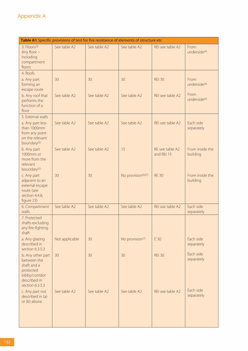
3. Floors(3)
Any floor –includingcompartmentfloors
4. Roofs
a. Any partforming anescape route
b. Any roof thatperforms thefunction of afloor
5. External walls
a. Any part lessthan 1000mmfrom any pointon the relevantboundary(5)
b. Any part1000mm ormore from therelevantboundary(5)
c. Any partadjacent to anexternal escaperoute (seesection 4.4.8,figure 23)
6. Compartmentwalls
7. Protectedshafts excludingany fire-fightingshaft
a. Any glazingdescribed insection 6.3.5.3
b. Any other partbetween theshaft and aprotectedlobby/corridordescribed insection 6.3.5.3
c. Any part notdescribed in (a)or (b) above.
REI see table A2
REI 30
REI see table A2
REI see table A2
RE see table A2and REI 15
RE 30
REI see table A2
E 30
REI 30
REI see table A2
See table A2
30
See table A2
See table A2
See table A2
30
See table A2
Not applicable
30
See table A2
See table A2
30
See table A2
See table A2
See table A2
30
See table A2
30
30
See table A2
See table A2
30
See table A2
See table A2
15
No provision(6)(7)
See table A2
No provision(7)
30
See table A2
Fromunderside(4)
Fromunderside(4)
Fromunderside(4)
Each sideseparately
From inside thebuilding
From inside thebuilding
Each sideseparately
Each sideseparately
Each sideseparately
Each sideseparately
Table A1 Specific provisions of test for fire resistance of elements of structure etc
Appendix A
122

8. Enclosure(which does notform part of acompartmentwall or aprotected shaft)to a:
a. protectedstairway
b. lift shaft
9. Fire-fightingshafts
a. Constructionseparating fire-fightingshaft from rest ofbuilding
b. Constructionseparating fire-fighting stair,fire-fighting liftshaft and fire-fightinglobby
10. Enclosure(which is not acompartmentwall ordescribed initem 7) to a:
a. protectedlobby
b. protectedcorridor
11. Sub-divisionof a corridor
12. Fire-resistingconstruction:
a. enclosingplaces of specialfire risk (see section6.3.2.2)(10)
b. fire-resistingsubdivisiondescribed insection 4.3.2.16,figure 18(b)
13. Cavity barrier (11)
14. Ceiling(figure 32)
REI 30(8)
REI 30
REI 120
REI 60
REI 60
REI 30(8)
REI 30(8)
REI 30(8)
REI 30
REI 30
E 30 and EI 15
EI 30
30
30
120
60
60
30
30
30
30
30
Not applicable
Not applicable
30
30
120
60
60
30
30
30
30
30
30
30
30(8)
30
120
60
60
30(8)
30(8)
30(8)
30
30
15
30
Each sideseparately
Each sideseparately
From side remotefrom shaft
From shaft side
Each sideseparately
Each sideseparately
Each sideseparately
Each sideseparately
Each sideseparately
Each sideseparately
Each sideseparately
From underside
Table A1 Specific provisions of test for fire resistance of elements of structure etc
Table A1 continued on next page
Appendix A
123

15. Ductdescribed insection 6.4.5
16. Casingaround adrainage systemdescribed insection 6.5,figure 35
17. Flue wallsdescribed insection 6.5,figure 36
18. Fire doors
E 30
E 30
EI half the periodspecified in tableA2 for thecompartmentwall/floor
See table C1
Not applicable
Not applicable
Not applicable
See table C1
30
30
Half the periodspecified in tableA2 for thecompartmentwall/floor
See table C1
No provision
No provision
Half the periodspecified in tableA2 for thecompartmentwall/floor
See table C1
From outside
From outside
From outside
Table A1 Specific provisions of test for fire resistance of elements of structure etc
Notes:
1. Part 21 for loadbearing elements, Part 22 for non-loadbearing elements, Part 23 for fire-protectingsuspended ceilings, and Part 24 for ventilation ducts.BS 476-8 results are acceptable for items tested orassessed before 1 January 1988.
2. Applies to loadbearing elements only (section 6.1.3 andappendix F).
3. Guidance on increasing the fire resistance of existingtimber floors is given in BRE Digest 208 Increasing thefire resistance of existing timber floors (BRE 1988).
4. A suspended ceiling should only be relied on tocontribute to the fire resistance of the floor if theceiling meets the appropriate provisions given in tableA3.
5. The guidance in section 7.2 allows such walls tocontain areas which need not be fire-resisting(unprotected areas).
6. Unless needed as part of a wall in item 5a or 5b.
7. Except for any limitations on glazed elements given intable A4.
8. See table A4 for permitted extent of uninsulated glazedelements.
9. The National classifications do not automaticallyequate with the equivalent classifications in theEuropean column, therefore products cannot typicallyassume a European class unless they have been testedaccordingly.
10. It is recommended that all rooms of special fire hazardshould have 60 minutes fire resistance, for propertyprotection purposes.
11. For property protection, cavity barriers should alsohave 30 minutes insulation fire resistance (rather than15min) unless:
• there are no combustible materials used in theconstruction of the building within 3m of thebarrier; and
• it is impossible or highly unlikely that combustiblematerials will at any time be stored within 3m ofeither side of the barrier. If flammable materials maybe present, fully-insulating (30min) barriers shallalways be used.
12. The guidance provided in Tables A1 and A4 is for theprime purpose of life safety. Levels of fire resistance forprotection of the building fabric and its contents mayneed to be modified accordingly, either for longerresistance times or higher levels of performance (eg,insulation as well as integrity). This may be appropriateto provide enhanced resilience of the structure againstthe effects of fire over longer exposure times in postflashover conditions than are routinely considerednormal for the provision of safe escape.
‘R’ is the European classification of the resistance to fireperformance in respect of loadbearing capacity; ‘E’ is theEuropean classification of the resistance to fireperformance in respect of integrity; and ‘I’ is the Europeanclassification of the resistance to fire performance inrespect of insulation.
Appendix A
124
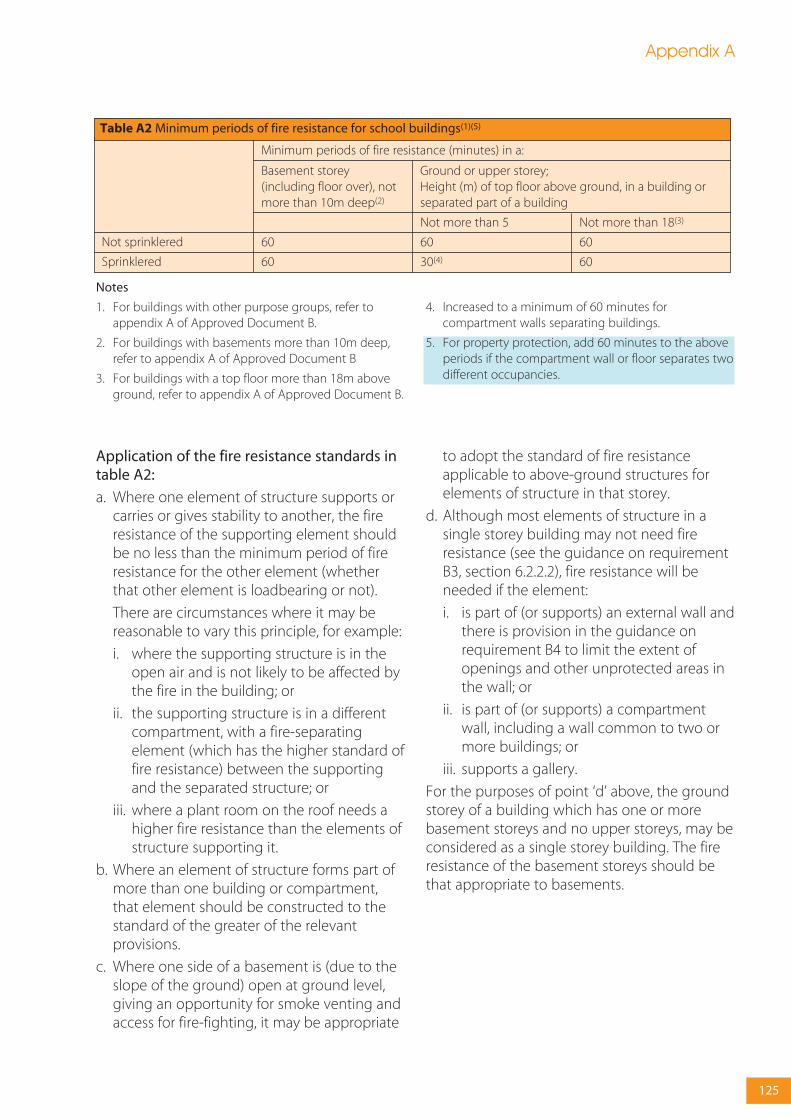
Notes
1. For buildings with other purpose groups, refer toappendix A of Approved Document B.
2. For buildings with basements more than 10m deep,refer to appendix A of Approved Document B
3. For buildings with a top floor more than 18m aboveground, refer to appendix A of Approved Document B.
4. Increased to a minimum of 60 minutes forcompartment walls separating buildings.
5. For property protection, add 60 minutes to the aboveperiods if the compartment wall or floor separates twodifferent occupancies.
Not more than 18(3)
60
60
Not sprinklered
Sprinklered
Basement storey(including floor over), notmore than 10m deep(2)
60
60
Not more than 5
60
30(4)
Table A2 Minimum periods of fire resistance for school buildings(1)(5)
Ground or upper storey;Height (m) of top floor above ground, in a building orseparated part of a building
Minimum periods of fire resistance (minutes) in a:
Appendix A
125
Application of the fire resistance standards intable A2:
a. Where one element of structure supports orcarries or gives stability to another, the fireresistance of the supporting element shouldbe no less than the minimum period of fireresistance for the other element (whetherthat other element is loadbearing or not).
There are circumstances where it may bereasonable to vary this principle, for example:
i. where the supporting structure is in theopen air and is not likely to be affected bythe fire in the building; or
ii. the supporting structure is in a differentcompartment, with a fire-separatingelement (which has the higher standard offire resistance) between the supportingand the separated structure; or
iii. where a plant room on the roof needs ahigher fire resistance than the elements ofstructure supporting it.
b. Where an element of structure forms part ofmore than one building or compartment,that element should be constructed to thestandard of the greater of the relevantprovisions.
c. Where one side of a basement is (due to theslope of the ground) open at ground level,giving an opportunity for smoke venting andaccess for fire-fighting, it may be appropriate
to adopt the standard of fire resistanceapplicable to above-ground structures forelements of structure in that storey.
d. Although most elements of structure in asingle storey building may not need fireresistance (see the guidance on requirementB3, section 6.2.2.2), fire resistance will beneeded if the element:
i. is part of (or supports) an external wall andthere is provision in the guidance onrequirement B4 to limit the extent ofopenings and other unprotected areas inthe wall; or
ii. is part of (or supports) a compartmentwall, including a wall common to two ormore buildings; or
iii. supports a gallery.
For the purposes of point ‘d’ above, the groundstorey of a building which has one or morebasement storeys and no upper storeys, may beconsidered as a single storey building. The fireresistance of the basement storeys should bethat appropriate to basements.

Description of suspendedceiling
Type W, X, Y or Z
Type X, Y or Z
Type Y or Z
Type Z
Height of building orseparated part (m)
Less than 18
18 or more
No limit
Type of floor
Not compartment
Compartment
any
any
Provision for fire resistanceof floor (minutes)
60 or less
less than 60
60
60 or less
More than 60
Table A3 Limitations on fire-protecting suspended ceilings (see table A1, note 4)
Notes:
1. Ceiling type and description (the change from TypesA-D to Types W-Z is to avoid confusion with Classes A-D (European)):
W. Surface of ceiling exposed to the cavity should beClass 0 or Class 1 (National) or Class C-s3, d2 orbetter (European).
X. Surface of ceiling exposed to the cavity should beClass 0 (National) or Class B-s3, d2 or better(European).
Y. Surface of ceiling exposed to the cavity should beClass 0 (National) or Class B-s3, d2 or better(European). Ceiling should not contain easilyopenable access panels.
Z. Ceiling should be of a material of limitedcombustibility (National) or of Class A2-s3, d2 orbetter (European) and not contain easily openableaccess panels. Any insulation above the ceilingshould be of a material of limited combustibility(National) or Class A2-s3, d2 or better (European).
2. Any access panels provided in fire protectingsuspended ceilings of type Y or Z should be secured inposition by releasing devices or screw fixings, and theyshould be shown to have been tested in the ceilingassembly in which they are incorporated.
3. The National classifications do not automaticallyequate with the equivalent European classifications,therefore, products cannot typically assume aEuropean class unless they have been testedaccordingly.
When a classification includes ‘s3, d2’, this means thatthere is no limit set for smoke production and/orflaming droplets/particles.
Appendix A
126

More than one stairway
Position of glazed element
1. Between a protected stairway(1) and:a. the accommodation; orb. a corridor which is not a protected corridor.
2. Between:a. a protected stairway(1) and a protected lobby orprotected corridor; orb. accommodation and a protected lobby.
3. Between the accommodation and a protectedcorridor forming a dead end
4. Between accommodation and any other corridor; orsubdividing corridors
5. Adjacent an external escape route described insection 4.3.2.17
6. Adjacent an external escape stair (see section 4.4.8and figure 23) or roof escape (see section 4.3.2.18)
A single stairway
Maximum total glazed area in parts of a building withaccess to:
Door leaf
25% ofdoor area
Unlimitedabove100mmfrom floor
Unlimitedabove100mmfrom floor
Notapplicable
Unlimitedabove1100mmfrom floor
Unlimited
Walls
Nil
Unlimitedabove1100mmfrom floor
Unlimitedabove1100mmfrom floor
Notapplicable
Unlimitedabove1100mmfrom floor
Unlimited
Door leaf
50% ofdoor area
Unlimitedabove100mmfrom floor
Unlimitedabove100mmfrom floor
Unlimitedabove100mmfrom floor
Unlimitedabove1100mmfrom floor
Unlimited
Walls
Unlimitedabove1100mm(2)
Unlimitedabove100mmfrom floor
Unlimitedabove1100mmfrom floor
Unlimitedabove100mmfrom floor
Unlimitedabove1100mmfrom floor
Unlimited
Table A4 Limitations on the use of uninsulated glazed elements on escape routes(These limitations do not apply to glazed elements which satisfy the relevant insulation criterion, see table A1)
Notes:
1. If the protected stairway is also a protected shaft (seesection 6.3.5) or a fire-fighting stair (see section 8.4)there may be further restrictions on the uses of glazedelements.
2. Measured vertically from the landing floor level or thestair pitch line.
3. The 100mm limit is intended to reduce the risk of firespread from a floor covering.For property protection, it is recommended to increasethe limit to 500mm (NB. AD M provides guidance thatvision panels in doors should have a lower edge notmore than 500mm above the floor).
4. Items 1 and 6 apply also to single storey buildings.
5. Fire-resisting glass should be marked with themanufacturer and product name.
6. Further guidance can be found in A guide to bestpractice in the specification and use of fire-resistant glazedsystems published by the Glass and Glazing Federation.
7. The guidance provided in Tables A1 and A4 is for theprime purpose of life safety. Levels of fire resistance forprotection of the building fabric and its contents mayneed to be modified accordingly, either for longerresistance times or higher levels of performance (eg,insulation as well as integrity). This may be appropriateto provide enhanced resilience of the structure againstthe effects of fire over longer exposure times in postflashover conditions than are routinely considerednormal for the provision of safe escape.
Appendix A
127

Covering material
1. Natural slates
2. Fibre reinforced cement slates
3. Clay tiles
4. Concrete tiles
Supporting structure
Timber rafters with or withoutunderfelt, sarking, boarding,woodwool slabs, compressed strawslabs, plywood, wood chipboard, orfibre insulating board
Designation
AA (National class) or BROOF(t4)(European class)
Table A5 Notional designations of roof coveringsPart 1. Pitched roofs covered with slates or tiles
Note: Although the table does not include guidance forroofs covered with bitumen felt, it should be noted thatthere is a wide range of materials on the market and
information on specific products is readily available frommanufacturers.
Designation
AA (National class) orBROOF(t4) (European class)
AA (National class) orBROOF(t4) (European class)
Roof covering material
1. Profiled sheet ofgalvanised steel,aluminium, fibrereinforced cement, or pre-painted (coil coated) steelor aluminium with PVC orPVF2 coating
2. Profiled sheet ofgalvanised steel,aluminium, fibrereinforced cement, or pre-painted (coil coated) steelor aluminium with PVC orPVF2 coating
Construction
Single skin withoutunderlay, or with underlayor plasterboard, fibreinsulating board orwoodwool slab
Double skin withoutinterlayer or with interlayerof resin bonded glass fibre,mineral wool slab,polystyrene orpolyurethane
Supporting structure
Structure of timber, steelor concrete
Structure of timber, steelor concrete
Table A5 Notional designations of roof coveringsPart 2. Pitched roofs covered with self-supporting sheet
A flat roof comprising of bitumen felt should (irrespective of the felt specification) be deemed designation AA(National class) or BROOF(t4) (European class) if the felt is laid on a deck constructed of 6mm plywood, 12.5mm woodchipboard, 16mm (finished) plain edged timber boarding, compressed straw slab, screeded woodwool slab, profiledfibre reinforced cement or steel deck (single or double skin) with or without fibre insulating board overlay, profiledaluminium deck (single or double skin) with or without fibre insulating board overlay, or concrete or clay pot slab (insitu or precast) and has a finish of:
a. bitumen-bedded stone chippings covering the whole surface to a depth of at least 12.5mm;
b. bitumen-bedded tiles of a non-combustible material;
c. sand and cement screed; or
d. macadam.
Table A5 Notional designations of roof coveringsPart 3. Flat roofs covered with bitumen felt
Appendix A
128

Covering material
1. Aluminium sheet
2. Copper sheet
3. Zinc sheet
4. Lead sheet
5. Mastic asphalt
6. Vitreous enamelled steel
7. Lead/tin alloy coated steel sheet
8. Zinc/aluminium alloy coated steelsheet
9. Pre-painted (coil coated) steelsheet including liquid-applied PVCcoatings
Supporting structure
Timber joists and tongued andgrooved boarding or plain edgedboarding
Steel or timber joists with deck of:woodwool slabs, compressed strawslab, wood chipboard, fibreinsulating board, or 9.5mm plywood.
Concrete or clay pot slab (in situ orprecast) or non-combustible deck ofsteel, aluminium or fibre cement(with or without insulation)
Designation
AA* (National class) or BROOF(t4)(European class)
AA (National class) or BROOF(t4)(European class)
AA (National class) or BROOF(t4)(European class)
Table A5 Notional designations of roof coveringsPart 4. Pitched or flat roofs covered by fully supported material
Notes: (*) Lead sheet supported by timber joists and plainedged boarding should be regarded as having a BAdesignation and is deemed to be designated CROOF(t4)(European class).
The National classifications do not automatically equatewith the equivalent classifications in the Europeancolumn; therefore, products cannot typically assume aEuropean class unless they have been tested accordingly.
References in BB 100 guidance tosituations where such materialsshould be used
1. refuse chutes meeting theprovisions in the guidance to B3,section 6.3.4.3
2. suspended ceilings and theirsupports where there is provision inthe guidance to B3, section 6.4.4.1,for them to be constructed of non-combustible materials
3. pipes meeting the provisions inthe guidance to B3, table 11
4. flue walls meeting the provisionsin the guidance to B3, figure 36
National class
a. Any material which when testedto BS 476- 11: 1982 does not flamenor cause any rise in temperature oneither the centre (specimen) orfurnace thermocouples.b. Totally inorganic materials such asconcrete, fired clay, ceramics, metals,plaster and masonry containing notmore than 1% by weight or volumeof organic material. (Use in buildingsof combustible metals such asmagnesium/aluminium alloysshould be assessed in eachindividual case).c. Concrete bricks or blocks meetingBS EN 771-1 :2003d. Products classified as non-combustible under BS 476-4:1970.
European class
a. Any material classified as class A1in accordance with BS EN 13501-1:2002. Fire classification ofconstruction products and buildingelements, Part 1 – Classification usingdata from reaction to fire tests.b. Products made from one or moreof the materials considered as ClassA1 without the need for testing asdefined in Commission Decision2003/424/EC of 6th June 2003amending Decision 96/603/ECestablishing the list of productsbelonging to Class A1 ‘Nocontribution to fire’ provided for inthe Decision 94/611/ECimplementing Article 20 of theCouncil Directive 89/106/EEC onconstruction products. None of thematerials shall contain more than 1%by weight or volume (whichever isthe more onerous) ofhomogeneously distributed organicmaterial.
Table A6 Use and definitions of non-combustible materials
Definitions of non-combustible materials
Note: The National classifications do not automaticallyequate with the equivalent classifications in the European
column, therefore products cannot typically assume aEuropean class unless they have been tested accordingly.
Appendix A
129

References in BB 100 guidance tosituations where such materialsshould be used
1. Stairs where there is provision inthe guidance to B1 for them to beconstructed of materials of limitedcombustibility (see section 4.5.4.1)
2. Materials above a suspendedceiling meeting the provisions in theguidance to B3, section 6.4.4.1
3. Reinforcement/support for fire-stopping referred to in the guidanceto B3, see section 6.5.4
4. Roof coverings meetingprovisions:
a. in the guidance to B3, section 6.3.3.6; orb. in the guidance to B4, table 15; or c. in the guidance to B4, figure 42
5. Roof deck meeting the provisionsof the guidance to B3, figure 28a
6. Class 0 materials meeting theprovisions in appendix A
7. Ceiling tiles or panels of any fireprotecting suspended ceiling (TypeZ) in table A3
8. Insulation above any fire-protecting suspended ceiling (TypeZ) in table A3
9. Storage lockers
National class
a. Any non-combustible materiallisted in table A6.
b. Any material of density 300 kg/m3
or more, which when tested to BS476-11:1982, does not flame and therise in temperature on the furnacethermocouple is not more than20°C.
c. Any material with a non-combustible core at least 8mm thickhaving combustible facings (on oneor both sides) not more than 0.5mmthick. (Where a flame spread rating isspecified, these materials must alsomeet the appropriate testrequirements).
Any of the materials (a), (b) or (c)above, or:d. Any material of density less than300kg/m3, which when tested to BS476-11:1982, does not flame formore than 10 seconds and the rise intemperature on the centre(specimen) thermocouple is notmore than 35°C and on the furnacethermocouple is not more than 25°C.
European class
a. Any material listed in table A6b. Any material/product classified asClass A2-s3, d2 or better in accordancewith BS EN 13501-1:2002 Fireclassification of construction productsand building elements, Part 1 –Classification using data from reactionto fire tests
Any of the materials/products (a) or (b)above.
Table A7 Use and definitions of materials of limited combustibility
Definitions of non-combustible materials
Notes:
1. The National classifications do not automatically equatewith the equivalent classifications in the Europeancolumn; therefore, products cannot typically assume aEuropean class unless they have been tested accordingly.
2. When a classification includes ‘s3, d2’, this means thatthere is no limit set for smoke production and/or flamingdroplets/particles.
Appendix A
130

Notes (National):
1. Materials and products listed under Class 0 also meetClass 1.
2. Timber products listed under Class 3 can be broughtup to Class 1 with appropriate proprietary treatments.
3. The following materials and products may achieve theratings listed below. However, as the properties ofdifferent products with the same generic descriptionvary, the ratings of these materials/products should besubstantiated by test evidence.
Class 0: Aluminium faced fibre insulating board, flameretardant decorative laminates on a calciumsilicate board, thick polycarbonate sheet,phenolic sheet and UPVC.
Class 1: Phenolic or melamine laminates on a calciumsilicate substrate and flame-retardantdecorative laminates on a combustiblesubstrate.
Notes (European):
For the purposes of the Building Regulations:
1. Materials and products listed under Class A1 also meetClasses A2-s3, d2, B-s3, d2, C-s3, d2 and D-s3, d2.
2. Materials and products listed under Class A2-s3, d2also meet Classes B-s3, d2, C-s3, d2 and D-s3, d2.
3. Materials and products listed under Class B-s3, d2 alsomeet Classes C-s3, d2 and D-s3, d2.
4. Materials and products listed under Class C-s3, d2 alsomeet Class D-s3, d2.
5. The performance of timber products listed under ClassD-s3, d2 can be improved with appropriate proprietarytreatments.
6. Materials covered by the CWFT process (classificationwithout further testing) can be found by accessing theEuropean Commission’s website via the link on theCLG website www.communities.gov.uk
7. The national classifications do not automaticallyequate with the equivalent classifications in theEuropean column, therefore products cannot typicallyassume a European class unless they have been testedaccordingly.
8. When a classification includes ‘s3, d2’, this means thatthere is no limit set for smoke production and/orflaming droplets/particles.
Rating
Class 0 (National)
Class 3 (National)
Class A1 (European)
Class A2-s3, d2 (European)
Class B-s3, d2 (European)
Class C-s3, d2 (European)
Class D-s3, d2 (European)
Material or product
1. Any non-combustible material or material of limited combustibility.(Composite products listed in table A7 must meet test requirements givenin appendix A)
2. Brickwork, blockwork, concrete and ceramic tiles.3. Plasterboard (painted or not with a PVC facing not more than 0.5mm
thick) with or without an air gap or fibrous or cellular insulating materialbehind.
4. Woodwool cement slabs.5. Mineral fibre tiles or sheets with cement or resin binding.
6. Timber or plywood with a density greater than 400kg/m3, painted orunpainted.
7. Wood particle board or hardboard, either untreated or painted.8. Standard glass reinforced polyesters.
9. Any material that achieves this class or is defined as ‘classified withoutfurther test’ in a published Commission Decision.
10. Any material that achieves this class or is defined as ‘classified withoutfurther test’ in a published Commission Decision.
11. Any material that achieves this class or is defined as ‘classified withoutfurther test’ in a published Commission Decision
12. Any material that achieves this class or is defined as ‘classified withoutfurther test’ in a published Commission Decision.
13. Any material that achieves this class or is defined as ‘classified withoutfurther test’ in a published Commission Decision.
Table A8 Typical performance ratings of some generic materials and products
Appendix A
131

Appendix BFire behaviour of insulating core panels
Insulating core panel systems are used forexternal cladding as well as for internalstructures. However, whilst both types of panelsystem have unique fire behaviourcharacteristics, it is those used for internalstructures that can present particular problemswith regard to fire spread.
These panels typically consist of an inner coresandwiched between and bonded to facings ofgalvanised steel, often with a PVC facing forhygiene purposes. The panels are then formedinto a structure by jointing systems, usuallydesigned to provide an insulating and hygienicperformance. The panel structure can be freestanding, but is usually attached to the buildingstructure by lightweight fixings or hangers inthe case of ceilings.
The most common forms of insulation inpresent use are:
• polyisocyanurate;
• polyurethane;
• mineral fibre;
• phenolic;
• polystyrene;
• extruded polystyrene; and
• composite polymers such as syntacticphenolic.
Fire behaviour of the core materialsand fixing systems
The degradation of polymeric materials can beexpected when exposed to radiated/conducted heat from a fire, with the resultingproduction of large quantities of smoke.
It is recognised that the potential for problemsin fires involving mineral fibre cores is generallyless than those for polymeric core materials.
In addition, irrespective of the type of corematerial, the panel, when exposed to the hightemperatures of a developed fire, will tend todelaminate between the facing and core
material, due to a combination of expansion ofthe metal facing and softening of the bond line.
Therefore once it is involved, either directly orindirectly in a fire, the panel will have lost mostof its structural integrity. Stability will then bedependant on the method of fixing to thestructure. For systems that are not fixed throughboth facings the stability of the system will thendepend on the residual structural strength ofthe non-exposed facing, the interlocking jointbetween panels and the fixing system.
Most jointing or fixing systems for thesesystems have an extremely limited structuralintegrity performance in developed fireconditions. If the fire starts to heat up thesupport fixings or structure to which they areattached, then there is a real chance of totalcollapse of the panel system.
Where panels are used as the lining to abuilding the insulating nature of these panels,together with their sealed joints, means that firecan spread behind the panels, hidden from theoccupants of occupied rooms/spaces. Withsome thermoplastic cores fire can also spreadbetween the panel facings.
This can prove to be as particular problem tofire-fighters as, due to the insulating propertiesof the cores, it may not be possible to track thespread of fire, even using infra red detectionequipment. This difficulty, together with that ofcontrolling the fire spread within and behindthe panels, is likely to have a detrimental effecton the performance of the fixing systems,potentially leading to their complete andunexpected collapse, together with anyassociated equipment.
Fire-fighting
When compared with other types ofconstruction techniques, these panel systemstherefore provide a unique combination ofproblems for fire-fighters, including:
132

Appendix B
133
• hidden fire spread within panels withthermoplastic cores;
• production of large quantities of black toxicsmoke;
• rapid fire spread leading to flashover; and
• hidden fire behind lining systems.
These four characteristics are common to bothpolyurethane and polystyrene cored panels,although the rate of fire spread in polyurethanecores is significantly less than that ofpolystyrene cores, especially when any externalheat source is removed.
In addition, irrespective of the type of panelcore, all systems are susceptible to:
• delamination of the steel facing;
• collapse of the system; and
• hidden fire spread behind the system.
Design recommendations
To identify the appropriate solution, a riskassessment approach should be adopted. Thiswould involve identifying the potential fire riskwithin the enclosures formed by the panelsystems and then adopting one or more of thefollowing at the design stage:
• removing the risk;
• separating the risk from the panels by anappropriate distance;
• providing a fire suppression system for therisk;
• providing a fire suppression system for theenclosure;
• providing fire-resisting panels; and
• specifying appropriate materials/fixing andjointing systems.
In summary the performance of the buildingstructure, including the insulating envelope, thesuperstructure, the substructure etc, must beconsidered in relation to their performance inthe event of a fire.
Specifying panel core materials
Where at all possible the specification of panelswith core materials appropriate to theapplication will help ensure an acceptable levelof performance for panel systems, wheninvolved in fire conditions.
The following are examples in the provision ofcore materials which may be appropriate to theapplication concerned.
Mineral fibre cores:
• cooking areas;
• hot areas;
• fire breaks in combustible panels;
• fire stop panels; and
• general fire protection.
All cores:
• chill stores;
• cold stores; and
• clean rooms.
Note: Core materials may be used in othercircumstances where a risk assessment hasbeen made and other appropriate fireprecautions have been put in place.
Specifying materials/fixing andjointing systems
The following are methods by which thestability of panel systems may be improved inthe event of a fire, although they may not all beappropriate in every case.
In addition the details of construction of theinsulating envelope should, particularly inrelation to combustible insulant cores, preventthe core materials from becoming exposed tothe fire and contributing to the fire load.
a. Insulating envelopes, support systems andsupporting structure should be designed toallow the envelope to remain structurallystable by alternative means such as catenaryaction following failure of the bond linebetween insulant core and facing materials.

134
This particularly relates to ceilings and willtypically require positive attachment of thelower faces of the insulant panels to supports.
b. The building superstructure, together withany elements providing support to theinsulating envelope, should be protected toprevent early collapse of the structure or theenvelope.
Note: Irrespective of the type of panel provided,it will remain necessary to ensure that thesupplementary support method supporting thepanels remains stable for an appropriate timeperiod under fire conditions. It is not practical tofire protect light gauge steel members such aspurlins and sheeting rails which provide stabilityto building superstructures and these may becompromised at an early stage of a fire.Supplementary fire-protected heavier gaugesteelwork members could be provided at widerintervals than purlins to provide restraint in theevent of a fire.
c. In designated high risk areas, considerationshould be given to incorporating non-combustible insulant cored panels into walland ceiling construction at intervals, orincorporating strips of non-combustiblematerial into specified wall and ceiling panels,in order to provide a barrier to firepropagation through the insulant.
d. Correct detailing of the insulating envelopeshould ensure that the combustible insulantis fully encapsulated by non-combustiblefacing materials which remain in place duringa fire.
e. The panels should incorporate pre-finishedand sealed areas for penetration of services.
General
Generally, panels or panel systems should notbe used to support machinery or otherpermanent loads.
Any cavity created by the arrangement ofpanels, their supporting structure or otherbuilding elements should be provided withsuitable cavity barriers.
Appendix B
135
All fire doors should have the appropriateperformance given in table C1 either:
a. by their performance under test to BS 476Fire tests on building materials and structures,Part 22 Methods for determination of the fireresistance of non-loadbearing elements ofconstruction, in terms of integrity for a periodof minutes, eg, FD30. A suffix (S) is added fordoors where restricted smoke leakage atambient temperatures is needed; or
b. as determined with reference to CommissionDecision 2000/367/EC of 3rd May 2000implementing Council Directive 89/106/EECas regards the classification of the resistanceto fire performance of construction products,construction works and parts thereof. All firedoors should be classified in accordance withBS EN 13501-2:xxxx, Fire classification ofconstruction products and building elements.Classification using data from fire resistancetests (excluding products for use in ventilationsystems). They are tested to the relevantEuropean method from the following:
• BS EN 1634-1:2000, Fire resistance tests for doorand shutter assemblies. Fire doors and shutters;
• BS EN 1634-2:xxxx Fire resistance tests for doorand shutter assemblies. Fire door hardware; and
• BS EN 1634-3:2001 Fire resistance tests for doorand shutter assemblies. Smoke control doors.
The performance requirement is in terms ofintegrity (E) for a period of minutes. Anadditional classification of Sa is used for alldoors where restricted smoke leakage atambient temperatures is needed.
The requirement (in either case) is for testexposure from each side of the door separately,except in the case of lift doors which are testedfrom the landing side only.
Any test evidence used to substantiate the fireresistance rating of a door or shutter should becarefully checked to ensure that it adequatelydemonstrates compliance and is applicable tothe complete installed assembly. Smalldifferences in detail (such as glazing apertures,intumescent strips, door frames andironmongery, etc) may significantly affect therating.
Note 1: The designation of xxxx is used forstandards that are not yet published. The latestversion of any standard may be used providedthat it continues to address the relevantrequirements of the Regulations.
Note 2: Until such time that the relevantharmonised product standards are published,for the purposes of meeting the BuildingRegulations, products tested in accordance withBS EN 1634-1 (with or without pre-fire testmechanical conditioning) will be deemed tohave satisfied the provisions provided that theyachieve the minimum fire resistance in terms ofintegrity, as detailed in table C1.
Many insurers recommend that all products (forthe protection of openings and services) shouldbe manufactured within the factory productioncontrol standards specified in ISO 9002 as aminimum by independently certified firms.
All fire doors should be fitted with a self-closingdevice except for fire doors to cupboards and toservice ducts which are normally kept lockedshut.
Appendix CFire doors
Note: All rolling shutters should be capable ofbeing opened and closed manually for fire-fighting purposes (see section 8.4.5).
Where a self-closing device would beconsidered a hindrance to the normal approveduse of the building, self-closing fire doors maybe held open by:
a. a fusible link (but not if the door is fitted in anopening provided as a means of escapeunless it complies with the next paragraphbelow); or
b. an automatic release mechanism actuated byan automatic fire detection and alarmsystem; or
c. a door closer delay device.
Two fire doors may be fitted in the sameopening so that the total fire resistance is thesum of their individual fire resistances, providedthat each door is capable of closing theopening. In such a case, if the opening isprovided as a means of escape, both doorsshould be self-closing, but one of them may befitted with an automatic self-closing device andbe held open by a fusible link if the other dooris capable of being easily opened by hand andhas at least 30 minutes fire resistance.
Because fire doors often do not provide anysignificant insulation, there should be somelimitation on the proportion of doorwayopenings in compartment walls. Therefore nomore than 25% of the length of a compartmentwall should consist of door openings, unless thedoors provide both integrity and insulation tothe appropriate level (see appendix A, table A2).
Note: Where it is practicable to maintain a clearspace on both sides of the doorway, then theabove percentage may be greater.
Roller shutters across a means of escape shouldonly be released by a heat sensor, such as afusible link or electric heat detector, in theimmediate vicinity of the door. Closure ofshutters in such locations should not beinitiated by smoke detectors or a fire alarmsystem, unless the shutter is also intended topartially descend to form part of a boundary toa smoke reservoir.
Unless shown to be satisfactory when tested aspart of a fire door assembly, the essentialcomponents of any hinge on which a fire dooris hung should be made entirely from materialshaving a melting point of at least 800ºC.
Except for lift entrance/landing doors, all firedoors should be marked with the appropriatefire safety sign complying with BS 5499-5:2002according to whether the door is:
a. to be kept closed when not in use (Fire doorkeep shut);
b. to be kept locked when not in use (Fire doorkeep locked shut); or
c. held open by an automatic releasemechanism or free swing device (Automaticfire door keep clear).
Fire doors to cupboards and to service ductsshould be marked on the outside; all other firedoors on both sides.
Tables A1 and A2 set out the minimum periodsof fire resistance for the elements of structure towhich performance of some doors is linked.table A4 sets out limitations on the use ofuninsulated glazing in fire doors.
BS 8214:1990 gives recommendations for thespecification, design, construction, installationand maintenance of fire doors constructed withnon-metallic door leaves.
Guidance on timber fire-resisting doorsets, inrelation to the new European test standard, maybe found in Timber Fire-Resisting Doorsets:maintaining performance under the newEuropean test standard, published by TRADA.
Guidance for metal doors is given in Code ofpractice for fire-resisting metal doorsets publishedby the DSMA (Door and Shutter Manufacturers’Association) in 1999.
Hardware used on fire doors can significantlyaffect performance in fire. Notwithstanding theguidance in this document, guidance isavailable in Hardware for fire and escape doorspublished by the Builders Hardware IndustryFederation.
Appendix C
136

Position of door
1. In a compartment wall separating buildings.
2. In a compartment wall:
a. Enclosing a protected shaft forming a stairwaysituated wholly or partly above the adjoiningground;
b. Enclosing a protected shaft forming astairway not described in (a) above;
c. Enclosing a protected shaft forming a lift orservice shaft;
d. Not described in (a), (b) or (c) above.
3. In a compartment floor
4. Forming part of the enclosures of:
a. a protected stairway; or
b. a lift shaft (see section 4.5.6.2); which does notform a protected shaft in 2(a), (b) or (c) above.
5. Forming part of the enclosure of:
a. a protected lobby approach (or protectedcorridor) to a stairway;
b. any other protected corridor; or
c. a protected lobby approach to lift shaft (seesection 4.5.6.2)
6. Affording access to an external escape route
7. Sub-dividing:
a. corridors connecting alternative exits;
b. dead-end portions of corridors from theremainder of the corridor
8. Any door within a cavity barrier
9. Any door forming part of the enclosure to aplace of special fire risk
Minimum fire resistance of doorin terms of integrity (minutes)when tested to BS 476 part 22(1)
As for the wall in which the dooris fitted, but a minimum of 60
FD 30S(2)
Half the period of fire resistanceof the wall in which it is fitted,but 30 minimum and with suffixS(2)
Half the period of fire resistanceof the wall in which it is fitted,but 30 minimum
As for the wall it is fitted in, butadd S(2) if the door is used forprogressive horizontalevacuation under the guidanceto B1
As for the floor in which it is fitted
FD 30S(2)
FD 30
FD 30S(2)
FD 20 (S)
FD 30S(2)
FD 30
FD 20S(2)
FD 20S(2)
FD 30
FD 20
Minimum fire resistance of doorin terms of integrity (minutes)when tested to the relevantEuropean Standard BS EN 1634-1
As for the wall in which the dooris fitted, but a minimum of 60
E30 Sa(3)
Half the period of fire resistanceof the wall in which it is fitted,but 30 minimum and with suffixSa(3)
Half the period of fire resistanceof the wall in which it is fitted,but 30 minimum
As for the wall it is fitted in, butadd Sa(3) if the door is used forprogressive horizontalevacuation under the guidanceto B1
As for the floor in which it is fitted
E30 Sa(3)
E30
E30 Sa(3)
E20 Sa(3)
E30 Sa(3)
E30
E20 Sa(3)
E20 Sa(3)
E30
E20
Table C1 Provision for fire doors in school buildings
Notes:
1. To BS 476: Part 22 (or BS 476: Part 8 subject toregulatory guidance)
2. Unless pressurization techniques complying with BS 5588:Part 4 Fire Precautions in the design, construction and use ofbuildings Code of Practice for smoke control using pressuredifferentials are used, these doors should also either:
(a) have a leakage rate not exceeding 3m3/m/hour (headand jambs only) when tested at 25 Pa under BS 476Fire tests on building materials and structures, section31.1 Methods for measuring smoke penetration through
doorsets and shutter assemblies, Method of measurementunder ambient temperature conditions; or
(b) meet the additional classification requirement of Sawhen tested on BS EN 1634-3, Fire resistance tests fordoor and shutter assemblies, Part 3 – Smoke control doors.
3. The National classifications do not automatically equatewith the equivalent classifications in the Europeancolumn, therefore products cannot typically assume aEuropean class unless they have been tested accordingly.
Appendix C
137

In addition to the guidance in this appendix, thedesigner may find the following referencesuseful:
• TRADA IS 1/13 The technology of fire-resisting doorsets.
• PD 6512 Pt 1 Guide for Fire doors.
• PD 6512 Guide to the performance of Glass.
• BS 8214: 1990 Code of Practice for fire doorassemblies with non-metallic leaves.
• BS 476 Pt 22 Methods for determination ofthe fire resistance of non-loadbearingelements of construction.
• BS 476 Pt 23 Methods for determination ofthe contribution of components to the fireresistance of of the structure.
• The Door and Hardware Federation (a mergerof the ABHM and the D&SMA)
Appendix C
138

The choice of fire extinguisher depends on thenature of the risks likely to be encountered.
Classes of fire
Fires can generally be classified into five groups,see BS EN 2: 1992 (including amendment 2004).Fire extinguishers provided should beappropriate to the specific risks found in thepremises in accordance with table D1.
Types of fire extinguisher
Different types of fire extinguisher are used fordifferent fire types. The main types areillustrated in figure D1, along with the types offire they are not suitable for.
The recommended type and general location offire-fighting apparatus is given in table D2.
Appendix DFire extinguishers
Class of fire
Class A
Class B
Class C
Class D
Class F
Description
Fires involving solid materials such aswood, paper or textiles
Fires involving flammable liquids such aspetrol, diesel or oils
Fires involving gases
Fires involving metals
Fires involving cooking oils such as indeep-fat fryers
Table D1 Class of fire
139
Figure D1 Types of fire extinguisher
The contents of an extinguisher is indicated by a zone of colour on the red body. Halon extinguishers are not shown since no newHalon production is permitted in the UK.
Main types of portable extinguishers, their uses and colour coding.
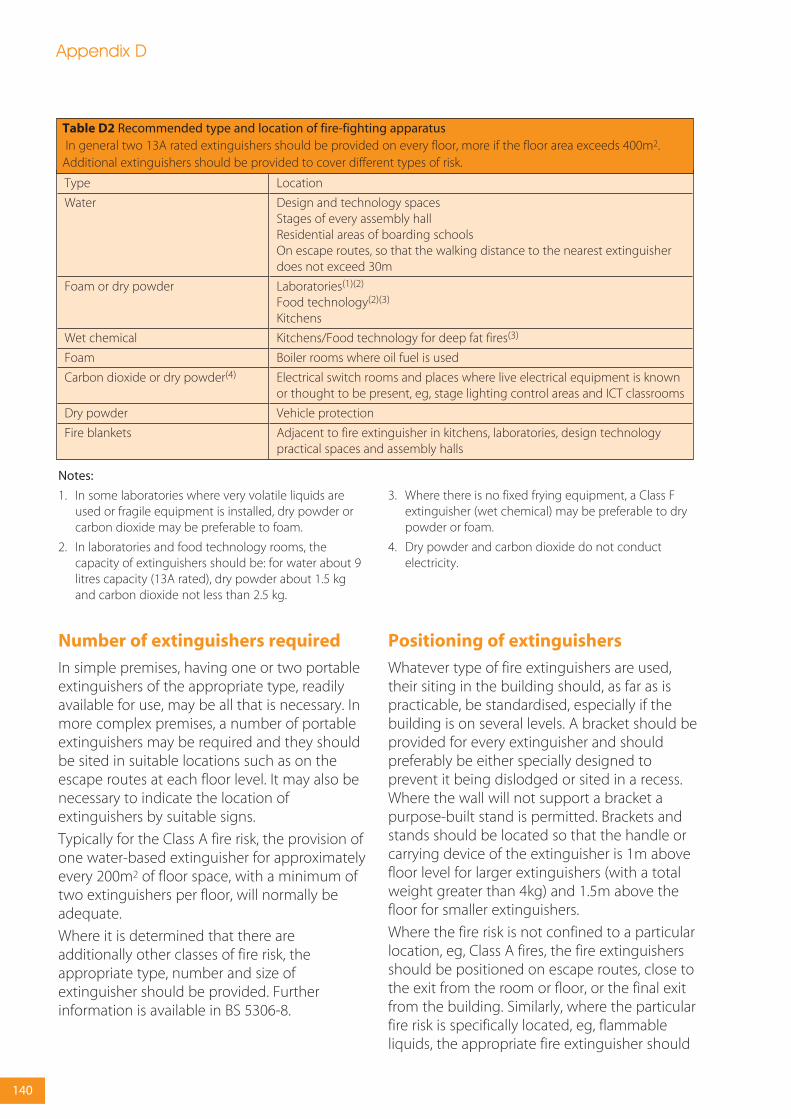
Number of extinguishers required
In simple premises, having one or two portableextinguishers of the appropriate type, readilyavailable for use, may be all that is necessary. Inmore complex premises, a number of portableextinguishers may be required and they shouldbe sited in suitable locations such as on theescape routes at each floor level. It may also benecessary to indicate the location ofextinguishers by suitable signs.
Typically for the Class A fire risk, the provision ofone water-based extinguisher for approximatelyevery 200m2 of floor space, with a minimum oftwo extinguishers per floor, will normally beadequate.
Where it is determined that there areadditionally other classes of fire risk, theappropriate type, number and size ofextinguisher should be provided. Furtherinformation is available in BS 5306-8.
Positioning of extinguishers
Whatever type of fire extinguishers are used,their siting in the building should, as far as ispracticable, be standardised, especially if thebuilding is on several levels. A bracket should beprovided for every extinguisher and shouldpreferably be either specially designed toprevent it being dislodged or sited in a recess.Where the wall will not support a bracket apurpose-built stand is permitted. Brackets andstands should be located so that the handle orcarrying device of the extinguisher is 1m abovefloor level for larger extinguishers (with a totalweight greater than 4kg) and 1.5m above thefloor for smaller extinguishers.
Where the fire risk is not confined to a particularlocation, eg, Class A fires, the fire extinguishersshould be positioned on escape routes, close tothe exit from the room or floor, or the final exitfrom the building. Similarly, where the particularfire risk is specifically located, eg, flammableliquids, the appropriate fire extinguisher should
Type
Water
Foam or dry powder
Wet chemical
Foam
Carbon dioxide or dry powder(4)
Dry powder
Fire blankets
Location
Design and technology spacesStages of every assembly hallResidential areas of boarding schoolsOn escape routes, so that the walking distance to the nearest extinguisherdoes not exceed 30m
Laboratories(1)(2)
Food technology(2)(3)
Kitchens
Kitchens/Food technology for deep fat fires(3)
Boiler rooms where oil fuel is used
Electrical switch rooms and places where live electrical equipment is knownor thought to be present, eg, stage lighting control areas and ICT classrooms
Vehicle protection
Adjacent to fire extinguisher in kitchens, laboratories, design technologypractical spaces and assembly halls
Table D2 Recommended type and location of fire-fighting apparatus In general two 13A rated extinguishers should be provided on every floor, more if the floor area exceeds 400m2.
Additional extinguishers should be provided to cover different types of risk.
Appendix D
140
Notes:
1. In some laboratories where very volatile liquids areused or fragile equipment is installed, dry powder orcarbon dioxide may be preferable to foam.
2. In laboratories and food technology rooms, thecapacity of extinguishers should be: for water about 9litres capacity (13A rated), dry powder about 1.5 kgand carbon dioxide not less than 2.5 kg.
3. Where there is no fixed frying equipment, a Class Fextinguisher (wet chemical) may be preferable to drypowder or foam.
4. Dry powder and carbon dioxide do not conductelectricity.

be near to the hazard, so located that they canbe safely used.
Extinguishers should be located in areas wherethey can be easily accessed by trained membersof staff, but not in areas where equipment isopen to misuse or vandalism.
Ideally no one should have to travel more than30m to reach a fire extinguisher.
Further information
For further information on fire extinguishers andother portable fire-fighting equipment, refer tothe RRO Guide for Educational Premises, Part 1section 3.4.2 and Part 2 section 3.1.
Appendix D
141
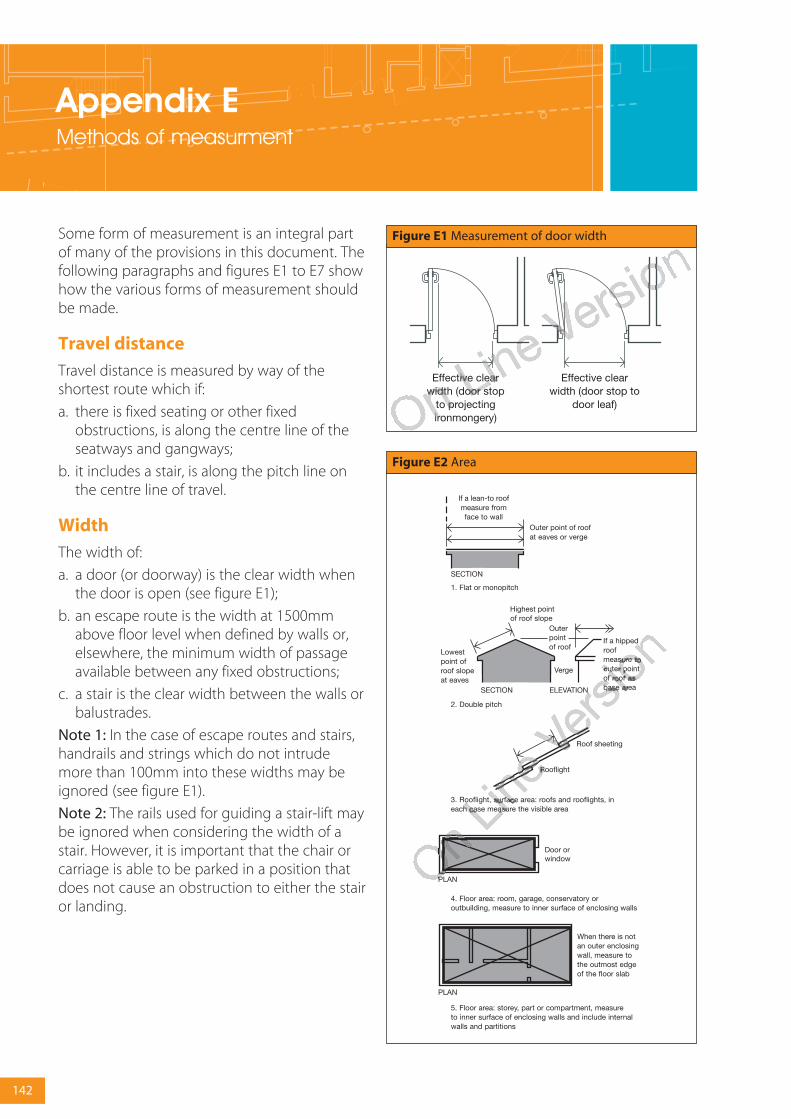
Appendix EMethods of measurment
Some form of measurement is an integral partof many of the provisions in this document. Thefollowing paragraphs and figures E1 to E7 showhow the various forms of measurement shouldbe made.
Travel distance
Travel distance is measured by way of theshortest route which if:
a. there is fixed seating or other fixedobstructions, is along the centre line of theseatways and gangways;
b. it includes a stair, is along the pitch line onthe centre line of travel.
Width
The width of:
a. a door (or doorway) is the clear width whenthe door is open (see figure E1);
b. an escape route is the width at 1500mmabove floor level when defined by walls or,elsewhere, the minimum width of passageavailable between any fixed obstructions;
c. a stair is the clear width between the walls orbalustrades.
Note 1: In the case of escape routes and stairs,handrails and strings which do not intrudemore than 100mm into these widths may beignored (see figure E1).
Note 2: The rails used for guiding a stair-lift maybe ignored when considering the width of astair. However, it is important that the chair orcarriage is able to be parked in a position thatdoes not cause an obstruction to either the stairor landing.
142
Effective clear width (door stop
to projecting ironmongery)
Effective clearwidth (door stop to
door leaf)
Figure E1 Measurement of door width
Figure E2 Area

Free area of smoke ventilators
The free area of a smoke ventilator, specifiedhere, from Approved Document B, may bemeasured by either:
a. the declared aerodynamic free area inaccordance with BS EN 12101-2:2003 Smokeand heat control systems. Specification fornatural smoke and heat exhaust ventilators; or,
b. The total unobstructed cross-sectional area,measured in the plane where the area is at aminimum and at right angles to the directionof air flow (see figure E6).
Appendix E
143
Figure E3 Height of building Figure E4 Number of storeys
Figure E5 Height of top storey in building
Note: A gallery is included as a storey, but not if it is a loadinggallery, fly gallery, stage grid, lighting bridge, or any galleryprovided for similar purposes, or for maintenance and repair.
To count the number of storeys in a building, or in a separatedpart of a building, count only at the position which gives thegreatest number and exclude any basement storeys.

Appendix E
144
A1 A2 A3 A4 A5
Free areameasured at right angles to air flow
Free area for louveredvent = A1+A2+A3+A4+A5
b.
a.
90°
Figure E6 Free area of smoke ventilators

Appendix FDefinitions
Note: Except for the items marked * (which arefrom the Building Regulations), these definitionswhich apply to BB 100 are largely taken fromApproved Document B: Fire Safety.
Access room A room through which passes theonly escape route from an inner room.
Accommodation stair A stair, additional to thator those required for escape purposes, providedfor the convenience of occupants.
Alternative escape routes Escape routessufficiently separated by either direction andspace, or by fire-resisting construction, toensure that one is still available should the otherbe affected by fire.
Alternative exit One of two or more exits, eachof which is separate from the other.
Appliance ventilation duct A duct provided toconvey combustion air to a gas appliance.
Atrium (plural atria) A space within a building,not necessarily vertically aligned, passingthrough one or more structural floors.
Note: Enclosed lift wells, enclosed escalatorwells, building services’ ducts and stairways arenot classified as atria.
Automatic release mechanism A devicewhich will allow a door held open by it to closeautomatically in the event of each or any one ofthe following:
a. detection of smoke by automatic apparatussuitable in nature, quality and location;
b. operation of a hand-operated switch fitted ina suitable position;
c. failure of electricity supply to the device,apparatus or switch; and
d. operation of the fire alarm system if any.
Basement storey A storey with a floor which atsome point is more than 1200mm below thehighest level of ground adjacent to the outsidewalls (however, see appendix A, table A2, forsituations where the storey is considered to bea basement only because of a sloping site).
Boundary The boundary of the land belongingto the building, or, where the land abuts a road,railway, canal or river, the centreline of thatroad, railway, canal or river (see figure 37).
*Building Any permanent or temporarybuilding but not any other kind of structure orerection. A reference to a building includes areference to part of a building.
Building Control Body A term used to includeboth Local Authority Building Control andApproved Inspectors.
Cavity barrier A construction, other than asmoke curtain, provided to close a concealedspace against penetration of smoke or flame orprovided to restrict the movement of smoke orflame within such a space.
Ceiling A part of a building which encloses andis exposed overhead in a room, protected shaftor circulation space (the soffit of a rooflight isincluded as part of the surface of the ceiling,but not the frame. An upstand below a rooflightwould be considered as a wall).
Circulation space A space (including aprotected stairway) mainly used as a means ofaccess between a room and an exit from thebuilding or compartment.
Class 0 A product performance classification forwall and ceiling linings. The relevant test criteriaare set out in appendix A.
Compartment (fire) A building or part of abuilding, comprising one or more rooms,spaces or storeys, constructed to prevent thespread of fire to or from another part of thesame building, or an adjoining building (a roofspace above the top storey of a compartment isincluded in that compartment. See also‘Separated part’).
Compartment wall or floor A fire-resistingwall/floor used in the separation of one firecompartment from another (constructionalprovisions are given in 6.3).
145

Concealed space or cavity A space enclosedby elements of a building (including asuspended ceiling) or contained within anelement, but not a room, cupboard, circulationspace, protected shaft or space within a flue,chute, duct, pipe or conduit.
Corridor access A design of a buildingcontaining flats in which each flat isapproached via a common horizontal internalaccess or circulation space which may include acommon entrance hall.
Dead end Area from which escape is possiblein one direction only.
Direct distance The shortest distance from anypoint within the floor area, measured within theexternal enclosures of the building, to thenearest storey exit ignoring walls, partitions andfittings, other than the enclosingwalls/partitions to protected stairways.
Element of structure
a. a member forming part of the structuralframe of a building or any other beam orcolumn;
b. a loadbearing wall or loadbearing part of awall;
c. a floor;
d. a gallery (but not a loading gallery, fly gallery,stage grid, lighting bridge, or any galleryprovided for similar purposes or formaintenance and repair);
e. an external wall; and
f. a compartment wall (including a wallcommon to two or more buildings. However,see the guidance to B3, section 6.2.2.2, forexclusions from the provisions for elements ofstructure).
Emergency lighting Lighting provided for usewhen the supply to the normal lighting fails.
Escape lighting That part of the emergencylighting which is provided to ensure that theescape route is illuminated at all material times.
Escape route Route forming that part of themeans of escape from any point in a building toa final exit.
European Technical Approval A favourabletechnical assessment of the fitness for use of aconstruction product for an intended use,
issued for the purposes of the ConstructionProducts Directive by a body authorised by amember State to issue European TechnicalApprovals for those purposes and notified bythat member State to the EuropeanCommission.
European Technical Approvals Issuing bodyA body notified under Article 10 of theConstruction Products Directive. The details ofthese institutions are published in the ‘C’ seriesof the Official Journal of the EuropeanCommunities.
Evacuation lift A lift that may be used for theevacuation of people in a fire.
Exit passageway A protected passagewayconnecting a protected stairway to a final exit(exit passageways should be protected to thesame standard as the stairway they serve).
External wall (or side of a building) Includes apart of a roof pitched at an angle of more than70º to the horizontal, if that part of the roofadjoins a space within the building to whichpersons have access (but not access only forrepair or maintenance).
Final exit The termination of an escape routefrom a building giving direct access to a street,passageway, walkway or open space and sitedto ensure the rapid dispersal of persons fromthe vicinity of a building so that they are nolonger in danger from fire and/or smoke.
Note: Windows are not acceptable as final exits
Fire damper Mechanical or intumescent devicewithin a duct or ventilation opening which isoperated automatically and is designed toprevent the passage of fire and which is capableof achieving an integrity E classification and/oran ES classification to BS EN 13501-3:2005 whentested to BS EN1366-2:1999. Intumescent firedampers may be tested to ISO 10294-5.
Fire and smoke damper Fire damper whichwhen tested in accordance with BS EN 1366-2:1999 meets the ES classification requirementsdefined in EN 13501-3:2005 and achieves thesame fire resistance in relation to integrity, asthe element of the building constructionthrough which the duct passes. Intumescentfire dampers may be tested to ISO 10294-2.
Appendix F
146
Fire door A door or shutter, provided for thepassage of persons, air or objects, which,together with its frame and furniture as installedin a building, is intended (when closed) to resistthe passage of fire and/or gaseous products ofcombustion and is capable of meeting specifiedperformance criteria to those ends. It may haveone or more leaves and the term includes acover or other form of protection to an openingin a fire-resisting wall or floor, or in a structuresurrounding a protected shaft).
Fire-fighting lift A lift designed to haveadditional protection, with controls that enableit to be used under the direct control of the Fireand Rescue Service in fighting a fire (seesections 8.2 – 8.4).
Fire-fighting lobby A protected lobbyproviding access from a fire-fighting stair to theaccommodation area and to any associated fire-fighting lift.
Fire-fighting shaft A protected enclosurecontaining a fire-fighting stair, fire-fightinglobbies and, if provided, a fire-fighting lift,together with its machine room (if relevant).
Fire-fighting stair A protected stairwaycommunicating with the accommodation areaonly through a fire-fighting lobby.
Fire-resisting (fire resistance) The ability of acomponent or construction of a building tosatisfy for a stated period of time, some or all ofthe appropriate criteria specified in the relevantstandard test (loadbearing capacity, integrityand insulation. See appendix A).
Fire-separating element A compartment wall,compartment floor, cavity barrier andconstruction enclosing a protected escaperoute and/or a place of special fire hazard.
Fire stop A seal provided to close animperfection of fit or design tolerance betweenelements or components, to restrict thepassage of fire and smoke.
Gallery A floor or balcony which does notextend across the full extent of a building’sfootprint and is open to the floor below.
Height (of a building or storey for thepurposes of BB 100) Height of a building ismeasured as shown in appendix E, figure E3
and height of the floor of the top storey aboveground is measured as shown in appendix E,figure E5.
Inner room Room from which escape ispossible only by passing through another room(the access room).
Material of limited combustibility A materialperformance specification that includes non-combustible materials and for which therelevant test criteria are set out in appendix A.
Means of escape Structural means whereby (inthe event of fire) a safe route or routes is or areprovided for persons to travel from any point ina building to a place of safety.
Measurement Width of a doorway, area, cubiccapacity, height of a building and number ofstoreys, see appendix E, figures E1 to E6. Fortravel distance and, width of escape route and astair, see appendix E.
Non-combustible material The highest levelof reaction to fire performance. The relevant testcriteria are set out in appendix A.
Notional boundary A boundary presumed toexist between buildings on the same site (seesection 7.3, figure 38).
Open spatial planning The internalarrangement of a building in which more thanone storey or level is contained in oneundivided volume, eg, split-level floors. For thepurposes of this document there is a distinctionbetween open spatial planning and an atriumspace.
Perimeter (of a building) The maximumaggregate plan perimeter, found by verticalprojection onto a horizontal plane (see section8.3, figure 43).
Pipe (for the purposes of section 6.5)Includes pipe fittings and accessories andexcludes a flue pipe and a pipe used forventilating purposes (other than a ventilatingpipe for an above around drainage system).
Places of special fire hazard Oil-filledtransformer and switch-gear rooms, boilerrooms, storage space for fuel or other highlyflammable substances and rooms housing afixed internal combustion engine. Additionallyin schools the list includes laboratories,
Appendix F
147

technology rooms with open heat sources,kitchens and stores for PE mats or chemicals.
Platform floor (access or raised floor) A floorsupported by a structural floor, but with anintervening concealed space which is intendedto house services.
Protected circuit An electrical circuit protectedagainst fire.
Protected corridor/lobby A corridor or lobbywhich is adequately protected from fire inadjoining accommodation by fire-resistingconstruction.
Protected shaft A shaft which enables persons,air or objects to pass from one compartment toanother and which is enclosed with fire-resisting construction.
Protected stairway A stair discharging througha final exit to a place of safety (including anyexit passageway between the foot of the stairand the final exit) that is adequately enclosedwith fire-resisting construction.
Relevant boundary The boundary which theside of the building faces, (and/or coincideswith) and which is parallel, or at an angle of notmore than 80º, to the side of the building (seesection 7.3, figure 37). A notional boundary canbe a relevant boundary.
Rooflight A dome light, lantern light, skylight,ridge light, glazed barrel vault or other elementintended to admit daylight through a roof.
Room (for the purposes of B2) An enclosedspace within a building that is not used solely asa circulation space (the term includes not onlyconventional rooms, but also cupboards thatare not fittings and large spaces such aswarehouses and auditoria. The term does notinclude voids such as ducts, ceiling voids androof spaces).
School A place of education for children olderthan 2 and younger than 19 years. Includesnursery schools, primary schools and secondaryschools as defined in the Education Act 1996.
Self-closing device A device which is capableof closing the door from any angle and againstany latch fitted to the door.
Note: Rising butt hinges which do not meet theabove criteria are acceptable where the door isin a cavity barrier.
Separated part (of a building) A form ofcompartmentation in which a part of a buildingis separated from another part of the samebuilding by a compartment wall. The wall runsthe full height of the part and is in one verticalplane (see section 6.3.3.3 and appendix E, figure E4).
Single storey building A building consisting ofa ground storey only (a separated part whichconsists of a ground storey only, with a roof towhich access is only provided for repair ormaintenance, may be treated as a single storeybuilding). Basements are not included incounting the number of storeys in a building(see appendix E).
Site (of a building) is the land occupied by thebuilding, up to the boundaries with land inother ownership.
Smoke alarm A device containing within onehousing all the components, except possiblythe energy source, necessary for detectingsmoke and giving an audible alarm.
Storey Includes:
a. any gallery; and
b. a roof, unless it is accessible only formaintenance and repair.
Storey exit A final exit, or a doorway givingdirect access into a protected stairway, fire-fighting lobby, or external escape route.
Suspended ceiling (fire-protecting) A ceilingsuspended below a floor, which contributes tothe fire resistance of the floor. Appendix A, tableA3, classifies different types of suspended ceiling.
Technical specification A standard or aEuropean Technical Approval Guide. It is thedocument against which compliance can beshown in the case of a standard and againstwhich an assessment is made to deliver theEuropean Technical Approval.
Thermoplastic material See appendix A
Travel distance (unless otherwise specified)The actual distance to be travelled by a personfrom any point within the floor area to thenearest storey exit, having regard to the layoutof walls, partitions and fittings.
Appendix F
148

Appendix F
149
Unprotected area In relation to a side orexternal wall of a building means:
a. window, door or other opening; and
Note: Windows that are not openable andare designed and glazed to provide thenecessary level of fire resistance and recessedcar parking areas shown in figure F1, neednot be regarded as an unprotected area.
b. any part of the external wall which has lessthan the relevant fire resistance set out insection 7.2; and
c. any part of the external wall which hascombustible material more than 1mm thickattached or applied to its external face,whether for cladding or any other purpose(combustible material in this context is anymaterial which does not have a Class 0rating.)
Figure F1 Recessed car parking areas
Note: The parking area should be:a. open fronted; andb. separated from the remainder of the building by a
compartment wall(s) and floor(s) having not less than theperiod of fire-resistance specified in table A2 in appendix A.

Appendix GFire safety information
Regulation 16B requires that, where buildingwork involves the erection or extension of arelevant building, or a relevant change of use ofa building, fire safety information shall be givento the responsible person at the completion ofthe project or when the building or extension isfirst occupied.
• ‘Fire safety information’ means informationrelating to the design and construction of thebuilding or extension, and the services,fittings and equipment provided in or inconnection with the building or extensionwhich will assist the responsible person tooperate and maintain the building orextension with reasonable safety.
• A ‘relevant building’ is a building to whichthe Regulatory Reform (Fire Safety) Order2005 applies (S.I. 2005/1541; see article 6) , orwill apply after the completion of buildingwork.
• A ‘relevant change of use’ is a materialchange of use where, after the change of usetakes place, the Regulatory Reform (FireSafety) Order 2005 will apply, or continue toapply, to the building.
• ‘Responsible person’ has the meaning givenin article 3 of the Regulatory Reform (FireSafety) Order 2005.
This appendix is only intended as a guide as tothe kind of information that should be provided.For clarity the guidance is given in terms ofsimple and complex buildings, however thelevel of detail required will vary from building tobuilding and should be considered on a case bycase basis.
Simple buildings
For most buildings basic information on thelocation of fire protection measures may be allthat is necessary. An as-built plan of thebuilding should be provided showing:
a. escape routes;
b. compartmentation and separation (ie,location of fire separating elements,including cavity barriers in walk-in spaces);
c. fire doors, self-closing fire doors and otherdoors equipped with relevant hardware (eg,panic locks);
d. locations of fire and/or smoke detectorheads, alarm call-points, detection/alarmcontrol boxes, alarm sounders, fire safetysignage, emergency lighting, fireextinguishers, dry or wet risers and other fire-fighting equipment and location of hydrantsoutside the building;
e. any sprinkler system(s), including isolatingvalves and control equipment;
f. any smoke-control system(s) (or ventilationsystem with a smoke-control function),including mode of operation and controlsystems;
g. any high-risk areas (eg, heating machinery);
h. specifications of any fire safety equipmentprovided, in particular any routinemaintenance schedules;
i. any assumptions in the design of the firesafety arrangements regarding themanagement of the building; and
j. any provision incorporated into the buildingto facilitate the evacuation of disabledpeople. This information can then be usedwhen designing suitable Personal EmergencyEscape Plans.
150

Appendix G
151
StoreRoom
Laboratory
Assemblypoint ClassroomClassroomClassroom
WC
WC
Figure G1 Example of a line drawing showing general fire safety precautions
Complex buildings
For more complex buildings a more detailedrecord of the fire safety strategy and proceduresfor operating and maintaining any fireprotection measures of the building will benecessary. Further guidance is available inBS5588-12:2004 Fire precautions in the design,construction and use of buildings: Managing firesafety (Annex A Fire Safety Manual.) Theserecords should include:
a. the fire safety strategy, including allassumptions in the design of the fire safetysystems (such as fire load). Any riskassessments or risk analysis;
b. all assumptions in the design of the firesafety arrangements regarding themanagement of the building;
c. escape routes, escape strategy (eg,simultaneous or phased) and muster points;
d. details of all passive fire safety measures,including compartmentation (ie, location offire separating elements), cavity barriers, firedoors, self-closing fire doors and other doorsequipped with relevant hardware (eg,electronic security locks), duct dampers andfire shutters;
e. fire detector heads, smoke detector heads,alarm call-points, detection/alarm controlboxes, alarm sounders, emergencycommunications systems, CCTV, fire safetysignage, emergency lighting, fire
extinguishers, dry or wet risers and other fire-fighting equipment, other interior facilities forthe Fire and Rescue Service, emergencycontrol rooms, location of hydrants outsidethe building, and other exterior facilities forthe Fire and Rescue Service;
f. details of all active fire safety measures,including:
• sprinkler system(s) design, includingisolating valves and control equipment;and
• smoke-control system(s) (or HVAC systemwith a smoke-control function) design,including mode of operation and controlsystems;
g. any high-risk areas (eg, heat bay equipment)and particular hazards;
h. as-built plans of the building showing thelocations of the above;
i. specifications of any fire safety equipmentprovided, including operational details,operators manuals, software, system zoningand routine inspection, testing andmaintenance schedules. Records of anyacceptance or commissioning tests;
j. any provision incorporated into the buildingto facilitate the evacuation of disabledpeople; and
k. any other details appropriate for the specificbuilding.
Fire warden to check
Break glass call point
Emergency lighting
Fire extinguisher
Fire exit sign
Self closing 30 minutefire door
30 minute fire-resistingconstriction
Key

Appendix HFire risk assessment
Risk assessment and cost-benefitanalysis tools
The tools are available on the enclosed CD-Romand updates will be provided on the DCSFwebsite www.teachernet.gov.uk/fire These are,a simple qualitative risk assessment tool, and amore comprehensive, quantitative, riskassessment and cost-benefit analysis tool.
Simple risk tool
This risk assessment tool is intended fordesigners, architects, fire safety engineers orothers who wish to assess the need forsprinklers in their proposed school building. Thetool comes in two slightly different forms, onefor existing sites (refurbishment or extension)and one for new schools. As recommended byBB 100, this tool should be used as a guide toassist in the risk-based decision-making process.The weightings assigned and scoring in thecurrent version are those agreed by the DCSFAdvisory Group at the time of release.
This survey and risk assessment will allow theuser to determine:
• type and scale of risk;
• trends or patterns in fire incidents involvingthe school;
• fire safety or fire protection measuresrequired; and
• efficiency of your chosen fire safety measures.
Completing the survey should take 15 – 30minutes. The user answers questions in thefour-part assessment that covers:
• incidence of arson and fire;
• environment and buildings;
• effectiveness of fire safety and fire protectionmeasures; and
• consequences of a fire.
Each question is considered in relation to theindividual building and scored accordingly. Forexample, in one particular question, if it isbelieved that out-of-hours use is reducing therisks to the school building, then score low.
152
Figure H1 Example question from the simple risk assessment tool
In the example below, if your school has had no cases of arson reported in the last 5 years then the risk would be perceived as low and ascore of 0 would be recorded:
If, however, your school had a few cases of arson over then last five years, then the score could be three of higher:
Low Risk 0 High Risk1 2 3 4 5
No cases of arson withinschool grounds
Arson common withinschool grounds
0 1 2 3 4 5
1. Arson (in the last 5 years)
Low Risk 0 High Risk1 2 3 4 5
No cases of arson withinschool grounds
Arson common withinschool grounds
0 1 2 3 4 5
1. Arson (in the last 5 years)
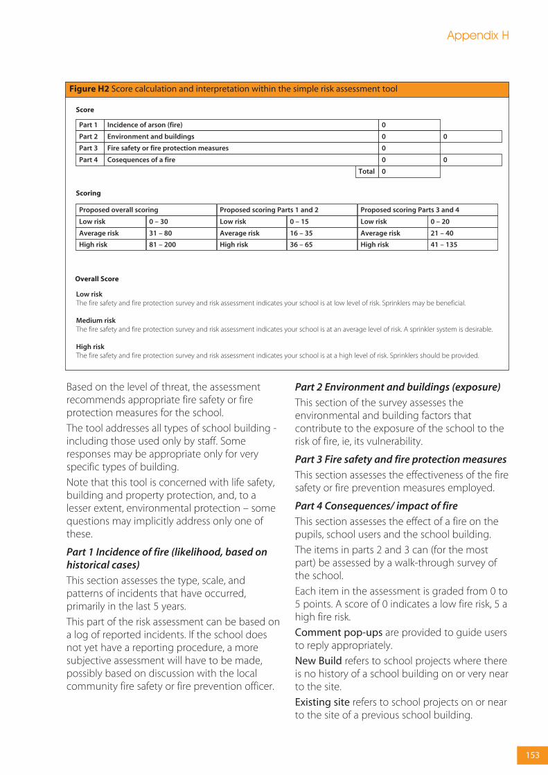
Based on the level of threat, the assessmentrecommends appropriate fire safety or fireprotection measures for the school.
The tool addresses all types of school building -including those used only by staff. Someresponses may be appropriate only for veryspecific types of building.
Note that this tool is concerned with life safety,building and property protection, and, to alesser extent, environmental protection – somequestions may implicitly address only one ofthese.
Part 1 Incidence of fire (likelihood, based onhistorical cases)
This section assesses the type, scale, andpatterns of incidents that have occurred,primarily in the last 5 years.
This part of the risk assessment can be based ona log of reported incidents. If the school doesnot yet have a reporting procedure, a moresubjective assessment will have to be made,possibly based on discussion with the localcommunity fire safety or fire prevention officer.
Part 2 Environment and buildings (exposure)
This section of the survey assesses theenvironmental and building factors thatcontribute to the exposure of the school to therisk of fire, ie, its vulnerability.
Part 3 Fire safety and fire protection measures
This section assesses the effectiveness of the firesafety or fire prevention measures employed.
Part 4 Consequences/ impact of fire
This section assesses the effect of a fire on thepupils, school users and the school building.
The items in parts 2 and 3 can (for the mostpart) be assessed by a walk-through survey ofthe school.
Each item in the assessment is graded from 0 to5 points. A score of 0 indicates a low fire risk, 5 ahigh fire risk.
Comment pop-ups are provided to guide usersto reply appropriately.
New Build refers to school projects where thereis no history of a school building on or very nearto the site.
Existing site refers to school projects on or nearto the site of a previous school building.
Appendix H
153
Figure H2 Score calculation and interpretation within the simple risk assessment tool
Score
Low riskThe fire safety and fire protection survey and risk assessment indicates your school is at low level of risk. Sprinklers may be beneficial.
Medium riskThe fire safety and fire protection survey and risk assessment indicates your school is at an average level of risk. A sprinkler system is desirable.
High riskThe fire safety and fire protection survey and risk assessment indicates your school is at a high level of risk. Sprinklers should be provided.
Part 1 Incidence of arson (fire) 0
Part 2 Environment and buildings 0 0
Part 3 Fire safety or fire protection measures 0
Part 4 Cosequences of a fire 0 0
Total 0
Proposed overall scoring Proposed scoring Parts 1 and 2 Proposed scoring Parts 3 and 4
Low risk
Average risk
High risk
0 – 30
31 – 80
81 – 200
Low risk
Average risk
High risk
0 – 15
16 – 35
36 – 65
Low risk
Average risk
High risk
0 – 20
21 – 40
41 – 135
Scoring
Overall Score

Risk assessment and cost-benefitanalysis tool
BRE have developed, on behalf of DCSF, aspreadsheet-based CBA tool. It consists of anumber of interlinked modules (represented byseparate sheets), which will each be describedbriefly.
The risk assessment (QRA) module considers thefrequencies and consequences of different firescenarios. Fires can start in different room types,eg, classrooms, cloakrooms, corridors, main hall,labs, offices and stores, and have probabilities ofgrowing to different sizes:
• minor = item first ignited;
• severe = fire damage to room of origin andsmoke damage beyond;
• major = fire damage beyond room of origin;and
• catastrophic = fire damage to most of thebuilding, total write-off.
The consequences of the different fire scenariosare quantified in terms of
• deaths and injuries;
• damage to building and contents;
• closure of facilities; and
• environmental impact (this is a bit subjective,although usually a small component of theoverall risk).
All of these are converted to monetary values.
The CBA module calculates the costs, per year,of the various fire safety systems (the tool is notjust restricted to sprinklers). Up-front installationcosts are converted to annual equivalents usingTreasury discounting rules. Various benefits, notrelated to risk reduction (eg, insurancepremiums) are also calculated by this module.
The CBA and QRA modules interact: thepackage of systems can either reduce theprobabilities (frequencies) of scenarios, or theirconsequences, or both. For example, sprinklerswould not prevent fires from starting, but theywould significantly reduce the probability that asmall fire can grow to a large one.
The basic data module just supplies themonetary conversion factors for the riskcomponents (eg, a life ≈ £1.5m) and a fewother constants.
The project data defines the school by thenumber of rooms of different types, and thetotal area of these.
Output takes the form of various charts, tables,etc.
Help is provided by the user manual, and alsopop-up comments in various cells that explainthe numbers that are input or calculated there.
Appendix H
154
Figure H3 Risk assessment and cost-benefit analysis tool
Scenarios Systems
QRA CBA
Help Interface (Excel)
Basic dataProject data
Output
Charts
Tables
Decision tools?
155
Appendix IReferences and further reading
British Standards
A complete list of British Standards can beobtained from the British Standards Institutewebsite. Alternatively, relevant standards mayalso be found in Approved Document B(volume 2, Appendix H).
DCSF Building Bulletins and otherpublications
Building Bulletin 7: Fire and the design ofeducational buildings (sixth edition), HMSO, 1992(withdrawn).
Building Bulletin 70: Maintenance of MechanicalServices. Maintenance and Renewal in EducationalBuildings, ISBN-0-11-270717-3.
Building Bulletin 93: Acoustic design of schools,ISBN 0 11 271105 7.
Building Bulletin 95: Schools for the Future.Designs for Learning Communities.
Building Bulletin 98: Briefing Framework forSecondary School Projects.
DfEE Managing School Facilities Guides; Guide4, Improving Security in schools, 1996.
DfEE Managing School Facilities Guides; Guide 6Fire Safety, 2000.
Schools Building and Design Unit; Key DesignGuidance for Schools: Access to information forschool design, April 2003 (updated August 2004).
Standard specifications, layouts and dimensions(SSLDs): Sprinklers in SchoolsInternal Doorsets in Schools Stairways in Schools Floor finishes in schoolsRoof coverings in schools
Health And Safety: Responsibilities And Powers.Organisation & Management, DfES/0803/2001.
CLG Approved documents and otherpublications
Approved documents are available a freedownloads from CLG:
http://www.planningportal.gov.uk/england/professionals/en/1115314110382.html
Hard copies can be obtained as a pricedpublication available from RIBA Bookshops MailOrder, 15 Bonhill Street, London, EC2P 2EA.
Approved Document B: (Fire safety) –Volume 2 – Buildings other than dwellinghouses(2006 Edition), published 18 December 2006,ISBN: 978 1 85946 262 1.
Approved Document E: Resistance to the passageof sound, published 27 April 2006, ISBN: 978 1 85946 204 1.
Approved Document K: Protection from falling,collision and impact, published 3 May 2006,ISBN: 978 1 85946 210 2.
Approved Document M: Access to and Use ofBuildings, published 3 May 2006,ISBN: 978 1 85946 211 9.
Approved Document N: Glazing – safety inrelation to impact, opening and cleaning,published 3 May 2006, ISBN: 978 1 85946 212 6.
Fire Safety Risk Assessment – Educational Premises,published 5 June 2006, ISBN: 978 1 85112 819 8.http://www.communities.gov.uk/index.asp?id=1162108
Arson Control Forum. Research Bulletin no. 10.Survey of school fires. December 2006.
Fire Statistics, United Kingdom, CLG, FireStatistics and Research Division. Various years.
Other government guidance
Safety signs and signals: the Health and Safety(Safety Signs and Signals) Regulations. Guidanceon Regulations, 1996, HSE publication,ISBN 0717608700.
BRE and Loss Prevention Councilreports
BRE 454: Multi-storey timber frame buildings – a design guide, 2003, ISBN: 8608 605 3.
BRE Digest 208: Increasing the fire resistance ofexisting timber floors, 1988, ISBN: 978 8608 359 7.
BRE Report: Design methodologies for smoke andheat exhaust ventilation, BR 368, 1999,ISBN: 978 8608 289 7.
BRE Report: External fire spread: Buildingseparation and boundary distances, BR 187, BRE 1991.
BRE Report: Fire performance of external thermalinsulation for walls of multi storey buildings, BR 135.
BRE Report: Fire safety of PTFE-based materialsused in buildings, BR 274, BRE 1994.
BRE Report: Guidelines for the construction of fire-resisting structural elements, BR 128, BRE 1988.
Loss Prevention Standard LPS 1162: Issue 3.1:16/09/05 Requirements and Tests for LPCBCertification of Fire Dampers 62.
Loss Prevention Standard LPS 1175: Issue 5.2:Requirements and Testing Procedures for the LPCBApproval and Listing of Burglary Resistant BuildingComponents, Strongpoints and Security EnclosuresS1175 – Doors, windows, shutters other façadeelements and enclosures.
Loss Prevention Standard LPS 1214: Issue 2.1:September 2005. Specification for testing andclassifying physical protection devices for personalcomputers and similar equipment.
Loss Prevention Standard LPS 1602: Issue 1:Requirements for LPCB Approval and Listing ofIntruder Alarm Movement Detectors.
Loss Prevention Standard LPS 1603: Issue 1:Requirements for LPCB Approval and Listing ofIntruder Alarm Control and Indicating Equipment.
LPC Design Guide for the Fire Protection ofBuildings, 2000 (FPA Design Guide for the FireProtection of Buildings).
Law, M., Heat Radiation from Fires and BuildingSeparation, Fire Research. Technical Paper No. 5,1963, Her Majesty's Stationery Office, London.
Industry guidance
A guide to best practice in the specification anduse of fire-resistant glazed systems, published bythe Glass and Glazing Federation, 44– 48Borough High Street, London, SE1 1XBwww.ggf.org.uk
Association for Specialist Fire Protectionpublications are freely available fromwww.asfp.org.uk
ASFP Blue Book: fire-resisting ductwork,ISBN: 1 87040 926 4.
ASFP Grey Book: Fire and smoke resisting dampers,ISBN: 1 87040 924 8.
ASFP Red Book: Fire Stopping and PenetrationSeals for the Construction Industry,ISBN: 1 87040 923 X.
ASFP Yellow Book: Fire protection for structuralsteel in buildings, 4th Edition, ISBN: 1 87040 925 6.
ASFP: Ensuring best practice for passive fireprotection in buildings, ISBN: 1 87040 919 1
CIBSE Guide E: Fire engineering, 2003. ISBN 10: 1-903287-31-6.ISBN 13: 978-1-903287-31-6.
Code of practice for fire-resisting metal doorsets,published by the DSMA (Door and ShutterManufacturers’ Association), 1999.
Code of Practice, Hardware for Timber Fire andEscape Doors, Issue 1, Hardware IndustryFederation, November 2000.
156

Appendix I
157
Gas Installations for Educational Establishments,IGE/UP/11, 2004. Published by the Institution ofGas Engineers (www.igem.org.uk).
Guidance Notes on Gas Safety in EducationalEstablishments, IM/25, 1989, available from DfESSchools Building and Design Unit or theInstitute of Gas Engineers. Now superseded bythe Institute of Gas Engineers UP11 Gasinstallations for Educational Establishments, 2004.
How to combat arson in schools, published bythe Arson Prevention Bureau, 2003.
Intumescent Fire Seals Association, IFSAInformation Sheet No 2 The role of intumescentmaterials in timber and metal based fire-resistingglazing systems, 1998.
Intumescent Fire Seals Association, the IFSACode 1999 Sealing apertures and servicepenetrations to maintain fire resistance.
SCI P 197 Designing for structural fire safety: Ahandbook for architects and engineers, 1999, ISBN:1 85942 074 5.
SCI Publication 288 Fire safe design: A newapproach to multi-storey steel-framed buildings,Second Edition 2000, ISBN: 1 85942 169 5.
Secured by Design (SBD), ACPO, seehttp://www.securedbydesign.com/apply/membership.aspx
Sprinklers for Safety: Use and Benefits ofIncorporating Sprinklers in Buildings andStructures, BAFSA 2006, ISBN: 0 95526 280 1.
The design and protection of new school buildingsand sites, Zurich Municipal Insurance, 2005.Download from www.zurichmunicipal.com
Timber Fire-Resisting Doorsets: maintainingperformance under the new European teststandard, 2002, published by TRADA,ISBN 1900510359.

158