building affordable intrusion detection system for
TRANSCRIPT

Building Affordable IntrusionDetection System for Internetof Things
Muhammad HaroonMaster’s Thesis Autumn 2018

Building Affordable Intrusion Detection Systemfor Internet of Things
Muhammad Haroon
17th December 2018

i

Acknowledgement
Foremost, i would like to thank my beloved family for their support and love. Icould never do it without them.
I would express my sincere gratitude to my supervisors Josef Noll and Magh-soud Morshedi for their guidance, motivation and patience. I am grateful tohave the chance to work with one of the best young talents in UiO, MaghsoudMorshedi.
My special thanks to Hårek Haugerud for his kindness and support.
Finally, i would like to thank my friends and colleagues, specially MadeleineVictoria Kongshavn for her time and valuable suggestions.
ii


Abstract
IoT is a pervasive technology that has revolutionized industry with value addedsolutions. Internet of Things (IoT) is a collection of small smart devices, whichcan communicate through communication networks. Due to a high profit poten-tial, it has gained an enormous attention of technology industry. IoT vendorsscramble for their profit share in the market, leaving security of these devicesalmost to negligence. It exposes IoTs to identity theft, privacy breaches and in-ternet downtime. Protecting IoTs has become one of the most researched topicsin cyber security paradigm. Due to contemporary nature of IoT devices, it iscomparatively difficult and complex to design and implement security softwareconsidering constraints attached to IoT. Specifically, an intrusion detection sys-tem (IDS) is a crucial tool in IoT security. Several commercial hardware andsoftware products have been claiming to solve these challenges by providing IDSsolutions but these solutions are costly and proprietary, which itself is an issue.This thesis presented an affordable intrusion detection system using low pricehardware Raspberry Pi (RPi) and open-source IDS Snort. Several tests wereconducted to check capability of Raspberry Pi of hosting Snort as an IDS aswell as to analyze Snort performance. The results showed that Rpi stood firmagainst several attack scenarios and Snort gave satisfactory performance. Thethesis provided a cost effective solution for IoT security to how to build an af-fordable intrusion detection system using low price hardware and open-sourceintrusion detection systems.
iv

Contents
List of Figures viii
List of Tables x
1 Introduction 31.1 Motivation . . . . . . . . . . . . . . . . . . . . . . . . . . . . . . 41.2 Problem Statement . . . . . . . . . . . . . . . . . . . . . . . . . . 51.3 Thesis Outline . . . . . . . . . . . . . . . . . . . . . . . . . . . . 6
2 Background 92.1 Internet of Things . . . . . . . . . . . . . . . . . . . . . . . . . . 9
2.1.1 IoT Ecosystem and Trend . . . . . . . . . . . . . . . . . 102.1.2 Areas of IoT Application . . . . . . . . . . . . . . . . . . 112.1.3 General Architecture of IoT . . . . . . . . . . . . . . . . . 132.1.4 IoT Protocols . . . . . . . . . . . . . . . . . . . . . . . . . 142.1.5 Challenges To IoT . . . . . . . . . . . . . . . . . . . . . . 15
2.1.5.1 IoT Security Challenges . . . . . . . . . . . . . 162.2 Intrusion Detection System . . . . . . . . . . . . . . . . . . . . . 19
2.2.1 IDS Placement Strategies . . . . . . . . . . . . . . . . . . 202.2.2 IDS Detection Methods . . . . . . . . . . . . . . . . . . . 21
2.3 Open Source IDS . . . . . . . . . . . . . . . . . . . . . . . . . . . 222.3.1 Snort . . . . . . . . . . . . . . . . . . . . . . . . . . . . . 22
2.3.1.1 Snort Architecture . . . . . . . . . . . . . . . . . 222.3.1.2 Configuration Modes . . . . . . . . . . . . . . . 242.3.1.3 Snort Rules . . . . . . . . . . . . . . . . . . . . . 25
2.3.2 Bro . . . . . . . . . . . . . . . . . . . . . . . . . . . . . . 262.3.3 Kismet . . . . . . . . . . . . . . . . . . . . . . . . . . . . 262.3.4 Suricata . . . . . . . . . . . . . . . . . . . . . . . . . . . . 26
2.4 Commercial Intrusion Detection Systems . . . . . . . . . . . . . . 272.4.1 McAfee NSP . . . . . . . . . . . . . . . . . . . . . . . . . 272.4.2 Trend Micro TippingPoint . . . . . . . . . . . . . . . . . . 272.4.3 Hillstone NIPS . . . . . . . . . . . . . . . . . . . . . . . . 272.4.4 Huawei NIP . . . . . . . . . . . . . . . . . . . . . . . . . . 27
2.5 Raspberry Pi . . . . . . . . . . . . . . . . . . . . . . . . . . . . . 28
v

2.5.1 Core Components . . . . . . . . . . . . . . . . . . . . . . 282.5.2 Operating System . . . . . . . . . . . . . . . . . . . . . . 292.5.3 Applications of RPi . . . . . . . . . . . . . . . . . . . . . 29
2.6 ELK Stack . . . . . . . . . . . . . . . . . . . . . . . . . . . . . . 302.7 Related Work . . . . . . . . . . . . . . . . . . . . . . . . . . . . . 31
3 Methodology 343.1 IDS Design Methodology . . . . . . . . . . . . . . . . . . . . . . . 343.2 System Design . . . . . . . . . . . . . . . . . . . . . . . . . . . . 35
3.2.1 System Components . . . . . . . . . . . . . . . . . . . . . 353.2.1.1 RPi Snort Gateway . . . . . . . . . . . . . . . . 363.2.1.2 Sensors . . . . . . . . . . . . . . . . . . . . . . . 363.2.1.3 Router . . . . . . . . . . . . . . . . . . . . . . . 363.2.1.4 IDS Test Machine . . . . . . . . . . . . . . . . . 363.2.1.5 Remote Monitoring Server . . . . . . . . . . . . 37
3.3 Snort Algorithms . . . . . . . . . . . . . . . . . . . . . . . . . . . 373.3.1 Aho-Corasick State Machine . . . . . . . . . . . . . . . . 373.3.2 Snort Implementation of AC . . . . . . . . . . . . . . . . 403.3.3 Detection and Processing of Rules . . . . . . . . . . . . . 42
3.4 The Approach . . . . . . . . . . . . . . . . . . . . . . . . . . . . . 443.4.1 Conditions . . . . . . . . . . . . . . . . . . . . . . . . . . 443.4.2 Attack scenarios . . . . . . . . . . . . . . . . . . . . . . . 443.4.3 Monitoring . . . . . . . . . . . . . . . . . . . . . . . . . . 45
4 Implementation 464.1 Compiling Snort on RPi . . . . . . . . . . . . . . . . . . . . . . . 464.2 Customizing Snort . . . . . . . . . . . . . . . . . . . . . . . . . . 464.3 Snort Instances . . . . . . . . . . . . . . . . . . . . . . . . . . . . 47
4.3.1 Snort Instance Eth0 . . . . . . . . . . . . . . . . . . . . . 484.3.1.1 Network . . . . . . . . . . . . . . . . . . . . . . . 484.3.1.2 Snort Eth0 Configuration File . . . . . . . . . . 484.3.1.3 Eth0 Rules File . . . . . . . . . . . . . . . . . . 48
4.3.2 Snort Instance Wlan0 . . . . . . . . . . . . . . . . . . . . 494.3.2.1 Network . . . . . . . . . . . . . . . . . . . . . . . 494.3.2.2 Wlan0 Rules . . . . . . . . . . . . . . . . . . . . 50
4.3.3 Logging . . . . . . . . . . . . . . . . . . . . . . . . . . . . 504.4 Configuring Beats on RPi . . . . . . . . . . . . . . . . . . . . . . 504.5 Configuring ELk server . . . . . . . . . . . . . . . . . . . . . . . . 514.6 Testing . . . . . . . . . . . . . . . . . . . . . . . . . . . . . . . . . 51
4.6.1 Test 1 . . . . . . . . . . . . . . . . . . . . . . . . . . . . . 524.6.2 Test 2 . . . . . . . . . . . . . . . . . . . . . . . . . . . . . 534.6.3 Test 3 . . . . . . . . . . . . . . . . . . . . . . . . . . . . . 544.6.4 Test 4 . . . . . . . . . . . . . . . . . . . . . . . . . . . . . 54
5 Results and Analysis 565.1 Test 1 . . . . . . . . . . . . . . . . . . . . . . . . . . . . . . . . . 56
vi

5.2 Test 2 . . . . . . . . . . . . . . . . . . . . . . . . . . . . . . . . . 585.3 Test 3 . . . . . . . . . . . . . . . . . . . . . . . . . . . . . . . . . 605.4 Test 4 . . . . . . . . . . . . . . . . . . . . . . . . . . . . . . . . . 615.5 Monitoring Server . . . . . . . . . . . . . . . . . . . . . . . . . . 63
5.5.1 Filebeat . . . . . . . . . . . . . . . . . . . . . . . . . . . . 645.5.2 Metricbeat . . . . . . . . . . . . . . . . . . . . . . . . . . 66
6 Discussion 696.1 Project Evaluation . . . . . . . . . . . . . . . . . . . . . . . . . . 696.2 The Approach . . . . . . . . . . . . . . . . . . . . . . . . . . . . . 696.3 Implementation and challenges . . . . . . . . . . . . . . . . . . . 706.4 Testing and Analysis . . . . . . . . . . . . . . . . . . . . . . . . . 716.5 Future Work . . . . . . . . . . . . . . . . . . . . . . . . . . . . . 73
7 Conclusion 74
Bibliography 75
Appendices 81
A Install and Configure Snort 82
B Hostapd and ISC server configurations 84
C Configuring Beats on RPi 87
D Setup ELK on Openstack 89
E Snort Instances and Gnuplot 93
F Snort Eth0 configurations 98
G Snort Eth0 Sample Rules 99
vii

List of Figures
1.1 IoT Market Growth Forecast showing IoT market trend in differ-ent IoT sectors. Sources: GrowthEnabler [68] . . . . . . . . . . . 4
2.1 major IoT companies and their sector of interest. Source:[5] . . . 112.2 Global share of IoT projects around the world. It also provides
top to lowest IoT segments Source: IoT Analytics [13] . . . . . . 122.3 General IoT communication architecture, showing most common
IoT sensors and devices. . . . . . . . . . . . . . . . . . . . . . . . 132.4 A comprehension of major IoT challenges in present and near
future. . . . . . . . . . . . . . . . . . . . . . . . . . . . . . . . . 162.5 IoT layers in the context of IoT component placement in IoT
architecture Source:[22] . . . . . . . . . . . . . . . . . . . . . . . . 172.6 The most common attacks against IoT Networks. . . . . . . . . 192.7 General IDS placement approach, the figure shows a distributed
approach IDS placement where IDS sensors placed in distributedlocations. . . . . . . . . . . . . . . . . . . . . . . . . . . . . . . . 21
2.8 An abstracted view of Snort operation process, form packet com-mencing to output. . . . . . . . . . . . . . . . . . . . . . . . . . . 23
2.9 Simple Snort Rule . . . . . . . . . . . . . . . . . . . . . . . . . . 252.10 Raspberry Pi Model B Block Diagram showing it’s main compon-
ents. . . . . . . . . . . . . . . . . . . . . . . . . . . . . . . . . . . 282.11 Components of ELK stack in their position of operation. Source:[75] 31
3.1 Adopted system design with it’s components and connection points. 353.2 Aho-Corasick state machine, showing data input and output steps.
Source[66] . . . . . . . . . . . . . . . . . . . . . . . . . . . . . . . 383.3 Form Beats on RPi to ELk server on Openstack. . . . . . . . . . 45
4.1 Shows how the Snort is configured on RPi with two Snort in-stances and Beats . . . . . . . . . . . . . . . . . . . . . . . . . . . 47
4.2 Figure created from system design figure, it shows attack vectorson each interface . . . . . . . . . . . . . . . . . . . . . . . . . . 52
viii
5.1 Test 1 -Memory and CPU consumption during test 1 at 100MBit/secdata rate. . . . . . . . . . . . . . . . . . . . . . . . . . . . . . . . 57
5.2 Test 2 -Memory and CPU consumption during test 2 at 300MBit/secdata rate. CPU consumption is increased but consistent as com-pared to test 1. . . . . . . . . . . . . . . . . . . . . . . . . . . . . 59
5.3 Test 3 - Memory and CPU consumption during BlackBurse at-tack, a very high CPU rate can be noticed with slight decrease inmemory consumption. . . . . . . . . . . . . . . . . . . . . . . . . 61
5.4 Test 4 -Memory and CPU consumption during dual attack, a veryhigh CPU rate can be seen because both of the Snort instances areoperational in detecting attacks. . . . . . . . . . . . . . . . . . . . 63
5.5 Syn-food attack on eth0 - Snort detects the attack and generatesalert, which is sent by Filebeat and processed by ELk index patterns. 64
5.6 ssh-bruteforce attack on wlan0 - It shows the generated alert bySnort after detection of the attack. . . . . . . . . . . . . . . . . . 65
5.7 blackNurse attack on eth0 - Snort successfully detects the attackand generates alerts. Figure shows the alert message on the ELKserver. . . . . . . . . . . . . . . . . . . . . . . . . . . . . . . . . . 65
5.8 XMAS scan detected on eth0 - Figure shows the detection of nmapXMAS scan, which normally belongs to first phases of a hackingattempt. . . . . . . . . . . . . . . . . . . . . . . . . . . . . . . . 65
5.9 GeoIP MAP - Showing the country location of attackers basedon their IP addresses. Red color countries are the top countrieswhere attacks where generated from. . . . . . . . . . . . . . . . . 66
5.10 Memory and system load - The line graph generated at ELKserver using Metricbeat data, showing memory and system loadfluctuations during a longer time span. . . . . . . . . . . . . . . . 67
5.11 Incoming and Dropped packets - The number of packets receivedand dropped by Ethernet interface. Based on Data shipped byMetricbeat. . . . . . . . . . . . . . . . . . . . . . . . . . . . . . . 67
ix

List of Tables
2.1 Shows an overview of IoT related entities and their respectiveparameter values. . . . . . . . . . . . . . . . . . . . . . . . . . . . 14
2.2 Comparison of RPi alternatives in terms of price and features. . 302.3 A summary of the major research IoT area with concerned threats
and detection methods. . . . . . . . . . . . . . . . . . . . . . . . 33
3.1 Specification details of RPi device used as an IDS. . . . . . . . . 363.2 Specification details of IDS testing machine i.e. attacking machine 37
4.1 Characteristics of Test 1, syn-flood at 100MBit/sec . . . . . . . 524.2 Test 2 characteristics and it’s values for a higher data rate of
300MBit/sec . . . . . . . . . . . . . . . . . . . . . . . . . . . . . 534.3 Test 3 characteristics while it used BlackNurse attack at relatively
low data rate . . . . . . . . . . . . . . . . . . . . . . . . . . . . . 544.4 Test 4 characteristics. It shows a dual attack on both interfaces
with different data rates. . . . . . . . . . . . . . . . . . . . . . . . 55
5.1 Test 1 - Snort I/O Statistics, showing Snort analysis and packetdrop rate. Percentage values are rounded. . . . . . . . . . . . . . 57
5.2 Test 2 - Snort I/O Statistics, showing Snort analysis and packetdrop rate. Analysis rate has dropped while outstanding rate hasincreased. . . . . . . . . . . . . . . . . . . . . . . . . . . . . . . . 58
5.3 Test 3 - Snort I/O Statistics, showing Snort analysis and packetdrop rate during BlackNurse attack. A higher packet commencerate by Snort can be noticed. . . . . . . . . . . . . . . . . . . . . . 60
5.4 Test 4 - Snort I/O Statistics for eth0, showing Snort statisticsduring dual interface attack. A very low analysis rate can beseen, with a very high outstanding packet rate. . . . . . . . . . . . 62
5.5 Test 4 - Snort I/O Statistics for wlan0, showing Snort statisticsduring dual interface attack. A very higher packet commence rateby Snort can be noticed with no packet drop. . . . . . . . . . . . . 62
x

Listings
3.1 AC implementation in Snort . . . . . . . . . . . . . . . . . . . . . 414.1 Static ip configuration . . . . . . . . . . . . . . . . . . . . . . . . 484.2 snort_wlan0.conf . . . . . . . . . . . . . . . . . . . . . . . . . . . 49
1

2

Chapter 1
Introduction
Since the very beginning of Internet back in the midst of 1960s at MIT, internetand technology in general, has evolved at a very fast pace, almost exponentiallyin terms of size, power and functionality.
This tremendous growth has not only changed the world which we now see andinteract with, but in fact, it has changed the prospective of human evolution.With all the benefits and good signs, there have been several short comings,which unfortunately could not evolve at the same pace as internet itself, forinstance, security of all these inter-connected devices, cyber security to be moreprecise.
Research in area of cyber security has held a noticeable speed. Due to unfore-seen nature of cyber threats, research in this area is always on passive mode,awaiting next cyber-attack to unleash. with advancements in technology, spe-cifically nano technology, computers and other technology related devices hasshrunk to minimal size with almost an exponential increase in processing powerand communication capability. these multi function smaller devices are cap-able of data gathering, data processing and communicating remotely over theinternet, these devices are generally referred as Internet of Things (IoT) . Dir-ect integration of these devices into the internet made it very difficult to followtraditional cyber security rules.
Unlike traditional computers and internet components, these devices or things,have a direct interaction with people and have a relatively higher degree of im-pact on quality of life. These devices are referred as Internet of Things (IoTs),term claimed to be first coined by K.Ashton [1] back in 1999. It is the IoT,which holds the triumph to close the gap between day to day activities andinternet. It has empowered the internet to such extent that it is very hard tothink about a day without internet.
The trend of IoT is growing at a tremendous speed. From baby monitors to
3

smart homes, autonomous cars to ICS sensors, health services to military opera-tions, IoT will be a vital organ of internet in upcoming era. Imagine, controllingentire home from a cell phone, for instance to control the temperature or mon-itor the door locks and home security or using smart wearable which monitorhealth and provide information about blood pressure, EKG, temperature, andoxygen levels from finger or forehead. There are numerous other IoT applica-tions which no wonder, looks like a scene of a Sci-fi movie. IoT has everythingto get excited for, but it is also a fact that these devices can be turned into anultimate nightmare due to insufficient security measures.
1.1 Motivation
According to Forbes [2], The global IoT market is expected to grow from $157Bin 2016 to $457B by 2020, attaining a marvelous Compound Annual GrowthRate (CAGR) of 28.5%. Discrete Manufacturing, Transportation and Logistics,and Utilities will lead all industries in IoT spending by 2020, averaging $40Beach.
Industrial manufacturing is predicted to increase from $472B in 2014 to $890Bin global IoT spending. Health-care and life sciences are projected to increasefrom $520B in 2014 to $1.335T in 2020, attaining a 17% CAGR.While Accordingto GrowthEnabler & MarketsandMarkets analysis[68], the global IoT marketshare will be dominated by three sub-sectors; Smart Cities (26%), IndustrialIoT (24%) and Connected Health (20%). Followed by Smart Homes (14%),Connected Cars (7%), Smart Utilities (4%) and Wearables (3%).
Similarly, advisory firm Bain predicts the most competitive areas of IoT willbe in the enterprise and industrial segments. It is been estimated that consumerapplications will generate $150B by 2020, with B2B applications being worthmore than $300B. Globally, enthusiasm for the Internet of Things has fueledmore than $80B in merger and acquisition (M&A) investments by major vendorsand more than $30B in venture capital, according to Bain’s estimates. Figure1.1 shows the year to year growth rate and global IoT market share.
Figure 1.1: IoT Market Growth Forecast showing IoT market trend in differentIoT sectors. Sources: GrowthEnabler [68]
4

The statistics and IoT market share predictions are no doubt astonishingbut unfortunately the so-called boom of IoT industry is pure profit oriented,overlooking the criticality and security aspects of such devices. Nonetheless,several security companies are being herded by the profit expectancy into thebusiness of IoT.
Researchers in security of these device are trying hard to catch the pace, infact, it is becoming one of the most researched fields in IT industry. Whichis a good sign, but there is too much to be done and several issues are tobe addressed. These issues have been the central point of concern for almostall the major IoT stack holders, independent research institutes, governmentregulations and standardization organizations [3].
To take part in the effort of implementation and deployment of IDS in IoTnetworks, this thesis is intended to build and test an intrusion detection systemfor IoT devices, using easy to access, relatively cheaper hardware Raspberry Piand a light weight open source Intrusion detection tool Snort.
1.2 Problem Statement
There are several commercial IDS (Intrusion Detection System) solutions avail-able for IoTs but these solutions are either too costly or not not designed spe-cifically for IoT environment. Most of these devices are designed for traditionalsystems, providing only a partial support for IoT devices. It is very importantto keep in view the resource constraints of IoT devices when designing an IDS,e.g. IoT devices, have low power and processing capability, are generally de-ployed in sparse-to-congested and critical areas. Also, commercial IDS solutionsare propriety and have cross-platform dependency which makes them restrictedto be used in wider range of IoT networks.
This thesis intends to develop an intrusion detection system which is afford-able, portable, less power consuming and open-source. The IDS device mustbe deployable in most of the IoT environments with minimal configuration re-quirements. To achieve this objective, a 35$ device Raspberry Pi (RPi) withopensource IDS Snort will be used in development of an affordable IDS solutionfor IoT devices. Moreover, this thesis will evaluate the performance of RPi interms of resource consumption. The thesis will try to answer following mainquestions:
a) How can we build an affordable and portable IDS solution using RPi andSnort?
b) Does RPi have enough resources to support Snort as an IDS, in terms ofresource consumption?
5

Except the core objectives, the thesis should also provide a remote monitoringcapability, which will give an insight of Snort alerts as well as performance met-rics of RPi. ELK (Elasticsearch, Logstash, Kibana) stack is used as monitoringserver on Openstack cloud.
1.3 Thesis Outline
The Thesis is organized as following:
Chapter1 - Introduction
This chapter provides general overview of cyber security, evolution of IoTs andits significance in Tech world. specifically, security aspects of IoTs, its futureresearch directions and what is this thesis aimed for?.
Chapter 2 - Background
This chapter goes through related and involved technologies in detail. A sum-mary of related research work is also presented.
Chapter 3 - Methodology
In this chapter, Research methodology is presented, along with a description ofexperiment design and result evaluation strategy.
Chapter 4 - Implementation
Chapter 4 provides details of how to practically implemented and test proposedIDS solution.
Chapter 5 - Results and Analysis
This chapter analyzes the experiment results and provides the justification ofthe results.
6

Chapter 6 - Discussion
A critical discussion on analysis and results, comprising the limitations andstrengths of the proposed work as well as future work.
Chapter 7 - Conclusion
Concluding the thesis by connecting problem statement and how the thesis haveaddressed the issues outlined.
7

8

Chapter 2
Background
This chapter will provide a technical overview of the tools, technologies and allthe main components which will be involved or relevant to this project. Withan emphasis on Internet of Things IoTs, Intrusion detection systems, as well asa review of related research material will be discussed and elaborated.
2.1 Internet of Things
Following the tradition of innovation in recent years, birth of Internet of Things(IoT) can be tracked back to Massachusetts institute of Technology MIT. Auto-ID center, founded in 1999, was assigned a task to work on a sensing technologycalled RFID (radio frequency identification). Auto-ID was responsible to designthe first ever architecture of IoT. IoT generally, refers to a very large collectionof small smart devices connected to internet.
The phenomenal growth of smart-phones and tablet PCs sling shot the num-ber of connected devices to an approx. of 12.5 billion in 2010, for a populationof 6.8 billion, increasing the ration from 0.08 to 1.84 devices per person. CiscoIBSG predicts that there will be 50 billion devices connected to the internet by2020[4]. It is worth a mention that estimates do not take into consideration thefast-paced evolution and advancements in device technology. Secondly, entirepopulation is taken into calculation, in fact, a large portion of population isstill not yet connected to the internet by a true sense of internet connection I.e.when it starts influencing their quality of life.
9
2.1.1 IoT Ecosystem and Trend
After the development of wireless sensor network (WSN) technology, severalstandardization technologies are formed, based on interest in market trend andtechnology selection. Technically, WSN can subdivided into IP based and non-IP-based solutions. Most of non-IP based solutions belong to well-known alli-ances like, Zigbee [47] and WAVE2M [48] for office manufacturing, automation,wirelessHart [49] and PROFIBUS [50] for industrial control systems (ICS). Theheterogeneous communication system of these alliances can produce several is-sues.
For the rest of IP-based devices, Internet Engineering Task Force (IETF)leads the standardization convoy to propose and develop standard protocolsby keeping in view the limitations and characteristics of concerned devices. Forinstance, IPV6 over Low Power Wireless Personal area Network (6LoWPAN) [6],routing protocol for low power and lousy networks (RPL) [7] and ConstrainedApplication Protocol (CoAP) [8].
Most of these protocols are aimed towards coping with protocols overhead,energy and memory consumption, and computational limitations of IoT devices[9].Several other institutions are working on standardization of IoT, for instance,IP Smart Object Alliance (IPSO) promotes IPv6 embedded devices for machine-to-machine (M2M) applications, PROFINET works on Ethernet standards forindustrial automation.
Regardless of the fact that most of IoTs are heterogeneous at lower pro-tocol layers but they do share common behavior at application layer. Thissimilar behavior leads to standardize application layer of IoT which is inde-pendent of underlaying communication networks. This responsibility is takenby European Telecommunication Standards Institute (ETSI) Technical Com-mittee (TC M2M) [10]. ETSI will have to specify service requirements, usecases, functional architecture and communication interfaces. To provide thebasis of one horizontal IoT platform, ETSI will bring common service layer toglobally accepted common agreed grounds.
Although several non-government entities are playing a major role in stand-ardization but there are still some areas where governments have to assist themin this regard. For instance, fragmented solutions and interoperability acrossvertical applications. More specifically, IoT related solutions are not well ac-cepted by the customers, severe privacy and security concerns are the majorfactors of customers hesitation. For these reasons, governments have to taketheir role to rectify the entire ecosystem of IoTs. For instance, US regulationauthority have provided a detailed action plan to standardize the developmentof smart grids [11]. Similarly, in Europe, eCall service for vehicle fitment is to bestandardize. While in China, IoT standardization and development has securedits place in China’s 12th five-year-plan [12]. Figure 2.1 provides an overview ofmajor IoT market players.
10

Figure 2.1: major IoT companies and their sector of interest. Source:[5]
2.1.2 Areas of IoT Application
A recent report issued by iot-analytics [13] provides a real-life analysis of IoTstatistics, based on the data collected from 1600 IoT projects worldwide. Thereport asserts that 367 projects are aimed for smart city, 265 for industrialsettings and connected building IoT projects secures a 3rd place, in a list of top10 ongoing projects. Americans are ahead in the race by a share of 45% in totalIoT projects, EU is at 35% and while rest of Asia contributes only for 16%.
It is also interesting to note that most of smart city projects are located inEurope, almost 45%, while Americans are mainly focusing on connected health55% and connected cars at 54% in north America. Asia is keener towards smartAgriculture products i.e. 31%. Figure 2.2 depicts the results, showing share ofIoT projects around the globe in different IoT sectors.
Some of the main IoT segments are explained as follows:
a) Smart City - By 2025, with more than 60% of the world population ex-pected to live in urban cities. By 2023, there will be 30 mega cities globally,with 55% in developing countries, such as China, India, Russia and LatinAmerica [14]. Smart city has become the number one IoT application areain 2018 as per report by IoT analytics. The immense growth in this sector isdue to the hundreds of projects initiated by private sector and governments
11

Figure 2.2: Global share of IoT projects around the world. It also provides topto lowest IoT segments Source: IoT Analytics [13]
around the world.
For instance, Singapore and Barcelona are the prominent examples in thisarea. In the segment of smart cities, biggest area of focus is smart traffic,comprising projects on monitoring and control of traffic, bike sharing, park-ing systems and smart buss lane while related minor projects include utilities,smart lighting, public safety and environmental monitoring. At the currenttime i.e. 2018, Europe accounts for the highest smart city initiatives.
b) Connected Industry - This area of IoT covers a vast range of hetero-geneous applications and devices. Equipment monitoring, and non-factoryenvironments have been a prime focus. Non-factory applications include as-set monitoring, and management of remote machinery such as drills, heavycranes, oil ridges and mining components etc.Cisco’s connected mining operation for Rio Tinto in Australia is a vivid ex-ample. Other mentionable connected industry applications include produc-tion floor monitoring, remote PLC control and automated quality controlsystem. For instance, Varroc, is using digital factory solutions from Altizonto connect industrial machines in the manufacturing environment [15]. How-ever, America plays the leading role in connected industry scenario.
c) Connected Building and Connected Car - Connected Building andCars – connected building has gained the largest increase in number of pro-jects since 2016 i.e. 7%. A majority of projects are aiming for facility auto-mation to reduce energy cost.For instance, Marriott hotel in China is utilizing building automation solu-tions, which are supposed to reduce energy cost up to 15%. Rest of theprojects are related to building security and to heating, ventilation and airconditioning HVAC. Connected cars has been also a top favorite for IoT pro-jects because it provides a wide-open ground for experimentation. Accordingto IoT analytics, vehicle diagnostics and fleet management are the prominentpoints of application i.e. 77% and 57% respectively. A recent example in this
12

context is TracknStop, an Ireland based software company has developed avehicle diagnostic solution which enables real-time tracking, sensor reading,monitoring and remote control for vehicles.
2.1.3 General Architecture of IoT
There is no universally agreed architecture of IoT networks, due to the fact thatit is highly use case dependent. Every organization who wish to deploy an IoTnetwork, has the freedom to design and implement according to their use caseand capacity.
Figure 2.1 presents the heterogeneous nature IoT technologies, where eachdeployment vertical seems unique and independent, but in fact, they do sharea lot of similarities at multiple layers of their operation. Similarly, many ofnetwork elements and several architectural components share certain commonproperties. This helps generalize the architecture of IoT, despite a varied natureof IoT entities. It can also be considered as a basic blue print on to which, avariety of architectural verticals can be designed and deployed.
Figure 2.3 presents a generalized architecture of IoT, which shows some ofthe main components involved in communication and data processing.
Figure 2.3: General IoT communication architecture, showing most commonIoT sensors and devices.
Some of the mutual attributes and challenges are summarized as follows:
1. Minimal to no human direct interaction of field IoT devices make it essen-tial to provide a reliable remote communication and management system.
2. In a large network, a huge amount of data is to be processed and analyzed,which makes it important to provide data storing, mining and sharingdevices.
13

3. In case of smart cities or industrial applications, a complex network isto be expected, enforcing the need to resolve addressing and congestionissues.
4. Large IoT networks are generally heterogeneous in nature, which means itdemands appropriate naming and addressing mechanisms, specifically forQoS requirements.
5. With appropriate management system, it is also vital to deploy an effi-cient remote monitoring system, which must provide a visual status of allnetwork devices.
2.1.4 IoT Protocols
As it has been discussed in earlier sections that IoTs tend to inherent a hetero-geneous nature, both in functionality and operability. IoT mostly communicatethrough wireless medium, which is more feasible due to their physical attrib-utes and environments IoTs operate in. In this regard, designing a standaloneprotocol which can fulfill all the IoT specific requirements is a difficult task. Atthe moment, no such standalone protocol exists.
There is a plethora of protocols and related technologies underlie the IoTtechnology. some of the main data protocols will be briefed in following section.Table 2.1 presents the layered approach towards the IoT technologies, whichcategorizes a variety of opensource and proprietary solutions.
Entities Identity
Infrastructure 6LowPAN, IPv4/IPv6, RPL, NanoIP, DTLS, TSMP etc.
Identification EPC, uCode, IPv6, URIs
Transport/Communication Wifi, LoRa, 802.15.4, Sigfox, Z-wave, Zigbee, WirelessHArt, NB-IoT
Discovery Physical web, mDNS, DNS-SD, UPnP, HyperCat
Data Protocols MQTT, CoAP, AMQP, Websocket, SMCP, XMPP, DDS, REST, LLAP etc.
Device Management TR-069, OMA-DM
Semantic JSON-LD, Web Thing Model
Multi-layer Frameworks Alljoyn, IoTivity,Weave, Homekit
Table 2.1: Shows an overview of IoT related entities and their respective para-meter values.
a) MQTT - (Message Queening Telemetry Transport) is a standard protocolprovided by Organization for the Advancement of Structured InformationStandards (OASIS) [16]. It is a lightweight publish/subscribe messaging
14
transport application level protocol. It is designed for IoTs and machine-to-machine communication. MQTT uses TCP/IP for communication and itcan provide a reliable point to point connection stream. For networking, ituses Ethernet, WiFi and cellular networks such as, 3G, 4G etc.
A common MQTT structure consists of three main components, publisher,broker and subscriber. Publisher is usually a small sensor device which sendsdata to broker. Subscribers are the applications connected to broker and sendthe collected data from broker to IT infrastructure. Main goal of MQTT isto provide remote monitoring i.e. telemetry, as its name implies.
Amazon now supports MQTT in their Amazon Web Services2, over bothIPv4 and IPv6 [17].
b) CoAP - (Constrained Application Protocol) is designed by Internet Engin-eering Task Force IETF to facilitate message transfer between machine-to-machine applications by offering various features such as, built in discovery,multi cast support and asynchronous message exchange.[18].
c) WebSocket - as like CoAP, Websocket protocol is also designed by IEFT[19]. It was developed as part of HTML5 initiative by implementing a JavaS-cript interface, which facilitates full duplex communication between clientand server. The WebSocket standard simplifies much of the complexityaround bi-directional web communication and connection management.
d) XMPP - (Extensible Messaging and Presence Protocol) Extensible Mes-saging and Presence Protocol (XMPP) is an open XML technology for real-time communication, which powers a wide range of applications includinginstant messaging, presence, collaboration, multi-part chat, voice and videocalls, content syndication and generalized routing to XML data [20]. it isdesigned to be extensible.
2.1.5 Challenges To IoT
Regardless the fact that the concept of IoT is very new, but it is rather im-mature. Surprising enough, it has grown its own ecosystem, comprising ofever-growing billions of heterogeneous devices, numerous protocols, almost non-uniform architectures, several parent/manufacturer organizations (mostly start-ups) with prime goal of mere profit, different function classes i.e. applicationfrom room temperature sensors to sensors in outer space, all of this diversityspawn challenges in every component of this ecosystem.
It is true, if said, that currently, IoT is in its non-equilibrium state. To proveits true worth and without making things more miserable, challenges to IoTsmust be rectified, or at least their effect must be minimized. Luckily, there havebeen several initiatives taken by public and private organizations to providesolutions and to raise awareness.
15

Challenges associated with IoT range from social issues to frightening securityconcerns. For instance, Ethical issues, which requires to explain user rights,raising public awareness etc. Legal Issues, demanding whether certain lawshave to be enforced or not, user consent, legal use of devices etc. Economic,which is mostly a concern for IoT producers or the benefactors of IoT in termsof direct profit.
It is directly connected with Legal issues on the long run. IoT business en-tities must provide reasonable Terms of Service, honest marketing! and a clearbusiness model. Last but not least, the most important, Technical and SecurityChallenges. Figure 2.4 depicts the scene, showing major issues associated withIoTs.
Figure 2.4: A comprehension of major IoT challenges in present and near future.
To reap the greatest from IoT, rectification of Technical and Security chal-lenges is vital. Since the thesis is aimed for rectification of one of the securityproblem, only security related issues will be discussed in next section.
2.1.5.1 IoT Security Challenges
A generic IoT system can be defined by using concept of layers i.e. perception,transportation and application layer. These layers come along with their owntype of weakness and security vulnerabilities. In [21], authors have analyzed IoTsecurity issues with possible security solutions. Figure 2.5 depicts the layeredsecurity perspective of IoTs, showing security challenges associated with IoT ondifferent layers.
16

Figure 2.5: IoT layers in the context of IoT component placement in IoT archi-tecture Source:[22]
I. Perception LayerPerception layer holds the physical features and components on IoT infra-structure. It can be logically compared to physical layer of OSI model.It provides features of data collection and processing on different commu-nication technologies, i.e. radio frequency identification (RFID), WirelessSensor Network (WSN).These devices are generally deployed randomlywithout security considerations. Due to limited node resources and broad-cast nature of these devices several security threats may result. Few ofthem are described as follows.
(a) Physical Attacks - Physical attacks, as the name explains itself, arethe close proximity attacks. Physical attacks can be, For instance,by changing original node with a malicious node, connecting to portsphysically, tempering with circuits and electronics, using Electromag-netic pulse (EMP) to disrupt communication.
(b) Data Transit Attacks - During the data transmission, integrity andconfidentiality of the data can be compromised, for instance, by Manin The Middle (MITM) attack, or by sniffing the broadcasted datatransmission.
(c) Impersonation Attacks - Authentication methods in IoT devices arehard to implement. It is very trickier to detect an imposter node withfake spoofed identity.
(d) DoS - A DoS attack can be unleashed on this layer by battery drainingi.e an attacker sending lots of packets, outage attacks, or when an edgedevice stops performing its normal operation.
II. Transportation LayerThis layer is responsible to provide data transportation facilities to Per-ception layer entities. It transmits the gathered information using commu-nication networks (WiFi, Ad-hoc, 4G etc.) to an information processingsystem. Few of the major threats at this layer are as follows:
17

(a) Routing Attacks – A node infected with a malware, may modify theactual routing and forwarding tables, enabling the node to forwardthe data to its peer system controlled by attacker, e.g. to a remoteCommand and Control Center (C&C).
(b) DoS - this layer can also be compromised by a DoS. For example,jam the transmission of radio signals.
(c) Injecting fraudulent packets – Done via insertion (where maliciouspackets that seem legit are generated and sent), manipulation (whenpackets are captured then modified) and replication (where the at-tacker captures packets between two things to replay them).
III. Application LayerThe application layer provides the services requested by customers. Forinstance, the application layer can provide temperature and air humiditymeasurements to corresponding users. The importance of this layer for theIoT is that it has the ability to provide and present IoT services in an easyto use manner, to meet the requirements of a user.
Many different IoT environments i.e. smart city, smart healthcare, andsmart factory can be implemented within this level. Moreover, an applica-tion support sublayer, to support all sorts of business services and to real-ize intelligent computation and resources allocation, could be implementedthroughout specific middleware and cloud computing platforms. Some ofthe major attacks related to Application Layer are explained below:
(a) Information Leakage - A vulnerable application software can easilylead to confidential information leakage. For instance, username andpasswords, Emails, home addresses, Credit Card info etc. applicationsoftware are notorious for bugs and vulnerabilities.
(b) Script Injection - Attackers can upload malicious codes in softwareapplications exploiting the known or unknown vulnerabilities. e.g.exploiting zero day vulnerabilities.
(c) DDoS - Distributed Denial of Service, is the most frequent and famousattack on application layer. It targets weak spots in Web applicationsand uses various techniques to compromise the application availabil-ity. One of the famous methods adopted by DDoS is using Botnets.A botnet is generally a large collection of compromised IoT devices.These compromised IoT devices work as a sleeping agent, keep waitingfor commands from their master or C&C center. A specially writtenmalware is used to create botnets. When needed, the botnets aresignaled by their master to send data traffic towards a specific target.DDoS attacks on application layer are evolving quickly, which makethese types of attacks very hard to detect and mitigate.
Figure 2.6 shows some of most common conventional attacks on different lay-ers of IoT operation. The Open Web Application Security Project (OWASP)
18

Figure 2.6: The most common attacks against IoT Networks.
also have a useful list of IoT Attack surface areas which they state should beunderstood by manufacturers, developers, researchers and companies looking todeploy IoT in their organizations [23].
Other IoT specific attacks are sink hole attack, where all traffic is directedfrom an area through a compromised node, where selective forwarding can followwith the attacker deciding what data to allow through.Sybil attack, a single nodepresents multiple identities to others in the network, so an attacker can be inmore than one place at once. Wormhole attack, an attacker tunnels messagesreceived in one part of the network over a low latency link and replays them ina different part. These type of attacks were first mentioned in [24].
2.2 Intrusion Detection System
Networks and information system are subject to get infected and hacked. Dueto free availability of vulnerability analysis tools, the trend of attacks has risen.Tools such as SubSeven [52], BackOrifce [53], Nmap [54], L0phtCrack [55] canall be used to scan, identify, probe and penetrate information systems.
An intrusion detection system is supposed to detect an intrusion and generateappropriate alert. IDS accomplish this by collecting information from differentsystem and network resources. After collection of information, it analyzes thedata for any suspicious behavior or security issue and generates alert. It canbe a hardware or a software, providing a variety of options to customize andimplement.
19

An intrusion detection system provides following core functionality:
• Monitoring and analysis of user and system activity
• Auditing of system configurations and vulnerabilities
• Assessing the integrity of critical system and data files
• Statistical analysis of activity patterns based on the matching to knownattacks
• Abnormal activity analysis
• Operating system audit
According to SANS [25], There are two main types of an intrusion detectionsystem as follows:
Network Intrusion Detection system (NIDS) performs an analysis for apassing traffic on the entire subnet. Works in a promiscuous mode, and matchesthe traffic that is passed on the subnets to the library of knows attacks. Oncethe attack is identified, or abnormal behavior is sensed, the alert can be send tothe administrator. Example of the NIDS would be installing it on the subnetwhere the firewalls are located in order to see if someone is trying to break intothe firewall.
Host Intrusion Detection System (HIDS) takes a snap shot of existingsystem files and matches it to the previous snap shot. If the critical system fileswere modified or deleted, the alert is sent to the administrator to investigate.The example of the HIDS can be seen on the mission critical machines, that arenot expected to change their configuration.
2.2.1 IDS Placement Strategies
Correct placement of IDS into network infrastructure is important. Althoughit is largely dependent on the environment and needs of the network, mostcommon places to deploy an IDS can be identified. Some of the recommendedplacement points for IDS are illustrated as:
• Between network and Extranet
• In the DMZ before the firewall to identify the attacks on servers in DMZ
• Between the firewall and network, to identify a threat in case of the firewallpenetration.
• In the Remote access environment
• If possible between servers and user community, to identify the attacksfrom the inside.
• On the intranet, FTP and database environment.
20
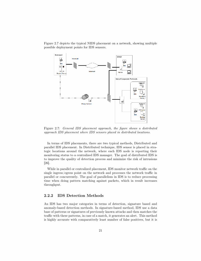
Figure 2.7 depicts the typical NIDS placement on a network, showing multiplepossible deployment points for IDS sensors.
Figure 2.7: General IDS placement approach, the figure shows a distributedapproach IDS placement where IDS sensors placed in distributed locations.
In terms of IDS placements, there are two typical methods, Distributed andparallel IDS placement. In Distributed technique, IDS sensor is placed in stra-tegic locations around the network, where each IDS node is reporting theirmonitoring status to a centralized IDS manager. The goal of distributed IDS isto improve the quality of detection process and minimize the risk of intrusions[26].
While in parallel or centralized placement, IDS monitor network traffic on thesingle ingress/egress point on the network and processes the network traffic inparallel or concurrently. The goal of parallelism in IDS is to reduce processingtime when doing pattern matching against packets, which in result increasesthroughput.
2.2.2 IDS Detection Methods
An IDS has two major categories in terms of detection, signature based andanomaly-based detection methods. In signature-based method, IDS use a database of patterns or signatures of previously known attacks and then matches thetraffic with these patterns, in case of a match, it generates an alert. This methodis highly accurate with comparatively least number of false positives, but it is
21

effective against known attacks only. It will be unable to detect unknown orzero-day attacks.
Anomaly based detection uses behavioral knowledge as its data base for intru-sion detection i.e. it needs a collection of statistics and facts of a normal systembehavior. Whenever it notices any deviation in normal behavior it raises analert. This method is hard to implement as it requires machine learning tech-niques and system training. Since there can be an unknown number of normalbehaviors, it is susceptible to a higher degree of false positives.
2.3 Open Source IDS
There are several open source intrusion detection systems available over theweb, each with its strengths and weakness. Since snort is part of this thesisproject, it will be presented in a good detail. While the other IDS systems willbe just briefly introduced.
2.3.1 Snort
Snort is an open source network intrusion detection and prevention system, cap-able of performing real-time traffic analysis and packet logging on IP networks.It can perform protocol analysis, content searching/matching, and can be usedto detect a variety of attacks and probes, such as buffer overflows, stealth portscans, CGI attacks, SMB probes, OS fingerprinting attempts [27]. it was createdby Martin Roesch in 1998 and is now maintained by Sourcefire Snort Team.
2.3.1.1 Snort Architecture
Snort functions by taking a series of steps and procedures. A typical snortprocedure involves packet sniffing, Packet Decoder/Acquisition, Pre-processor,Detection Engine and Output. Although it depends on the mode of deployment,but a general architecture of snort can be depicted. Figure 2.8 shows snortoperation architecture. The figure shows a typical Snort architecture consistingof it’s operational steps.
22

Figure 2.8: An abstracted view of Snort operation process, form packet commen-cing to output.
Packet Acquisition is the first step in intrusion detection, in this phaseeach packet is captured and identified by its structure. It uses libpcap libraryto capture packets, as Snort does not inherently posses such capability. Aftercapturing the packets, these packets are then passed on to the next phase calledpreprocessor.
Preprocessor is a collection of modular plugins and is one of the core com-ponent of Snort. There are several preprocessors offered by snort, which arecategorized in two types by the mode of their operation. First type is respons-ible to do complex tasks by adding an extra layer of analysis. This is done in caseif signature-based detection cannot be translated into rules to detect intrusion.The second type allows the modular plugins analyze the packets for suspiciousbehavior and modify them accordingly, so that the detection engine could inter-pret these packets with accuracy. For instance, malformed or obfuscated URLgoes through prepossesses for normalization such that pattern matching couldbe performed with precision, with minimal risk of sneaking through detectionengine.
Detection Engine is the main detection module, it performs signature de-tection and parsing based on the database of rules it contains. For faster pro-cessing these rules are loaded into memory. After arrival of a packet, detectionengine inspects the packets by matching its header and payload with loadedrules in memory. Snort uses first match then exit logic, which means when a
23

rule matches it generates the alert and then moves to next packet inspection.This phase is notorious for memory and processing consumption, which makesit a difficult choice for IoTs. During a heavy traffic flow, this phase leads to ahigher packet drop.
Output works below the detection engine and in fact, it is a component of de-tection engine itself. The Output stage logs intrusion alerts that were triggeredby the detection engine. These logs can be saved in different databases that canbe used for third party security information and event management systems likeSnorby [56], ACID [57], ELK Stack [58] or BASE [59] which provide a visualand understandable output than the logs in raw form.
2.3.1.2 Configuration Modes
Snort can be configured to run into three different mods, namely, sniffer mode,packet logger mode and network intrusion detection mode. These modes arefurther discussed as follows:
• Sniffer mode is configured to sniff the ongoing traffic, without generatingalerts and applying any rules, logically, it can be compared with Tcpdump[60], while ran as sniffer. Advantage of using Snort in sniffing mode overother sniffer tools is that it provides a good summary of captured packetswhich helps for an easy troubleshooting.
• When Snort runs in packet logger mode, it collects every packet it seesand places it in a directory hierarchy based upon the IP address of one ofthe hosts in the datagram. After specifying a logging directory Snort caneasily be run as logger mode by running ./snort -dev -l ./log or ./snort -l./log -b . -b switch tells the snort to log traffic into a single binary file, intoTcpdump binary format. It is very easy to read these binary formattedlogs by using any sniffer, such as, Tcpdump or Ethereal. Snort can alsoread the packets back by using the -r switch, which puts it into playbackmode.
It is possible to manipulate the data in the file in a number of ways throughSnort’s packet logging and intrusion detection modes, as well as with theBPF interface that’s available from the command line. For example, tosee the ICMP packets from the log file, simply specify a BPF filter at thecommand line and Snort will only see the ICMP packets in the file i.e../snort -dvr packet.log icmp.
• Network intrusion detection system mode provides threat detection andanalysis, by using a database of rules and filters. to enable Network Intru-sion Detection System (NIDS) mode, use ./snort -d -l ./log -c snort.confcommand, this will configure Snort to run in its most basic NIDS form,
24

logging packets that trigger rules specified in the snort.conf in plain ASCIIto disk using a hierarchical directory structure.
2.3.1.3 Snort Rules
Snort uses a simple, lightweight rules description language that is flexible andquite powerful. These rules can be downloaded from snort community database.These databases are updated periodically with disclosure of new threats andvulnerabilities. It is also possible to customize the rules according one’s ownneeds.
Snort rules are divided into two logical sections, the rule header and the ruleoptions. The rule header contains the rule’s action, protocol, source and des-tination IP addresses, netmask and the source/destination ports information.The rule option section holds alert messages and a detailed description, whichis used by detection engine to determine that which parts of the packet shouldbe inspected to decide if the rule action should be taken. Figure 2.9 shows asimple snort rule: explaining sequentially from left to right:
Figure 2.9: Simple Snort Rule
Rule Header
• alert - Rule action, Snort will generate an alert when the set condition ismet.
• any - Source IP, Snort will look at all sources.
• any - Source port, Snort will look at all ports.
• -> - Direction, From source to destination.
• $HOME_NET - Destination IP, using the HOME_NET value from thesnort.conf file.
• any - Destination port, Snort will look at all ports on the protected net-work.
Instead alert option, other options are drop and log, which provide Snort inlinefunctionality and logging respectively.
25

Rule Options
• msg:"ICMP test" - Snort will include this message with the alert.
• sid:1000001 - Snort rule ID, all numbers less than 1,000,000 are reserved.for custom rules, any arbitrary number above that limit can be used.
• rev:1 - Revision number, This option allows for easier rule maintenanceand is used for version control.
• classtype:icmp-event – Categorizes the rule as an “icmp-event”, one of thepredefined Snort categories. This option helps with rule organization.
These rules are highly flexible in terms of customization. Following the syntax,a Snort rule can be written in a variety of ways with multiple option to increasedetection accuracy. for instance, Pearl compatible regular expressions PCREscan also be used.
2.3.2 Bro
Bro is an open-source network traffic analyzer. It is primarily a security monitorthat inspects all traffic on a link in depth for signs of suspicious activity. Brosupports a wide range of traffic analysis tasks even outside of the security do-main, including performance measurements and helping with trouble-shooting[28].
2.3.3 Kismet
Kismet is a network detector, packet sniffer and an intrusion detection system802.11 wireless LANs[81]. It can be used with almost any wireless card whichsupport monitoring mode. It can detect both wireless access points and wirelessclients and their mutual association. It has the ability to log sniffed packetsand save them in pcap formats for later analysis. It can detect non-configurednetworks, probe requests, and level of wireless encryption used on a given accesspoint.
It consists of three main parts, a drone, which can be used to collect packetsand pass them to server, a server for interpretation of received packets, and theclient which communicates with the server and displays the information servercollects.
2.3.4 Suricata
Suricata is an open source intrusion detection system (IDS) and intrusion pre-vention system (IPS). It was developed by the Open Information Security Found-ation (OISF) and was first released in January 2010. It is a rule based IP/ID
26

system that utilizes externally developed rule sets to monitor network trafficand provide alerts to the system administrator when suspicious events occur. itfeatures unified output functionality and Plug&Play library options to acceptcalls from other applications[29].
2.4 Commercial Intrusion Detection Systems
There are several Commercial ID/IP systems available. some major productsare as follows:
2.4.1 McAfee NSP
The McAfee Network Security Platform (NSP) [61], is a network threat andintrusion prevention solution that protects systems. It can support up to 32million connections on a single appliance uses intelligence to find and blockadvanced targeted attacks on the network. a typical NSP setup can cost around$10,000.
2.4.2 Trend Micro TippingPoint
TippingPoint [62] identifies and blocks malicious traffic, prevents malware in-fections, ensures network availability and resiliency, and enhances network per-formance. The solution offers network traffic inspection throughput up to 120Gbps. Starting price of TippingPoint T Series is $6000, which can go as highas $72,000.
2.4.3 Hillstone NIPS
The Hillstone Network-based IPS (NIPS) [63] appliance offers intrusion pre-vention, anti-virus, application control, advanced threat detection, abnormalbehavior detection, a cloud sandbox and a cloud-based security managementand analytic platform. It can identify more than 3,000 applications, includingmobile and cloud. It’s package price starts from $18,000.
2.4.4 Huawei NIP
Huawei Network Intelligent Protection (NIP) [64] provides virtual patches, webapplication protection, client application protection, anti-malware, antivirus,anti-DDoS, application sensing, control on IPv4 and IPv6 networks. It’s pricestarts from $2,000.
27

Commercial intrusion detection systems can be deployed in large corpora-tions. Because of very high pricing, these commercial solutions are not feasiblefor medium to small organizations. An open source solution with a proper con-figuration can also satisfy security needs of an organization. In [30], authorshave provided a good comparison of open source and commercial IDSs.
2.5 Raspberry Pi
The Raspberry Pi [65], also referred as RPi, is a single board minicomputerdeveloped at United Kingdom by Raspberry Pi Foundation for the purpose ofpromoting computer science education in developing countries. It was primarilyaimed to be a low cost device but powerful enough to support several experi-mental scenarios, ranging from small school projects to robotics. Figure 2.10shows the block diagram of Raspberry Pi model B.
Figure 2.10: Raspberry Pi Model B Block Diagram showing it’s main compon-ents.
2.5.1 Core Components
Some of the main components of Raspberry Pi are introduced below:
Processor
The first generation RPis were equipped with Broadcom BCM2835 system ofchip (SoC), which included a 700 MHz ARM1176JZF-S processor, VideoCore
28

IV graphics processing unit (GPU) and RAM. It has a level 1 (L1) cache of 16KB and a level 2 (L2) cache of 128 KB. The level 2 cache is used primarily bythe GPU. The SoC is stacked underneath the RAM chip.
Memory
Original B boards were allocated 256 MB of split-able memory, which means128 MB was allocated to GPU, while the rest was reserved for CPU. In furtherreleases of model B board, a dynamic memory allocation method was adopted,which could dynamically split memory to GPU and CPU. Raspberry Pi 3 B+comes with 1 GB of RAM memory.
Networking Components
The Raspberry Pi 3 and Pi Zero W (wireless) have 2.4 GHz WiFi 802.11n (150Mbit/s) and Bluetooth 4.1 (24 Mbit/s) based on the Broadcom BCM43438FullMAC chip. Raspberry Pi 3 B+ comes with dual-band IEEE 802.11b/g/n/acWiFi and Gigabit Ethernet supporting up to 300 Mbit/sec.
2.5.2 Operating System
By default, Raspberry Pi is native to Raspbian, a Debian-based Linux distribu-tion. It is available for download from RPi Foundation’s website [65] for free.It also offers several other choices of operating system for RPi, e.g. UbuntuMATE, RISC OS and Windows 10 IoT Core. Except these, there are numerousoperating systems supported by RPi which includes both non-Linux based andLinux-based operating systems.
2.5.3 Applications of RPi
Due to its small size, very low price and power full customization features,RPi has been the most favorite technology for researchers, science teachers,automation industries and independent science enthusiast. A RPi can be turnedinto almost any anything if its components support it. For instance, prototypingof electrical equipment was a tedious and costly job, now it can be done by mere$35 of RPi, by utilizing its GPIO and peripherals.
It’s applications range from media server, arcade Machine, personal securitysystem for network devices, a mini computer, automation, robotics and countlessother. It had made the life easier for all those technology related people whoare looking for cheap and customize-able solutions.
29

There are several alternative single board computers available in the market.Depending on the features and price, these computers can be a good alternativeto RPi, for instance, some offer a higher CPU and memory and are equippedwith higher bandwidth Ethernet ports. Table 2.2 shows some of the alternativesthat can be chosen as an alternative to RPi.
Name CPU Memory Ethernet Price
Orange Pi Plus2[76] 1.6GHz 2GB Gigabit 49$
Asus Tinker Board[77] 1.8GHz 2GB Gigabit 60$
Banana Pi M3[78] 1.8GHz 2GB Gigabit 72$
Firefly RK3288 Plus[79] 1.8GHz 4GB Gigabit 79$
armStoneA9[80] 1.2GHz 4GB Gigabit 330$
Table 2.2: Comparison of RPi alternatives in terms of price and features.
2.6 ELK Stack
ELK, also known as Elastic stack is acronym for three open source projects,Elasticsearch, Logstash, and Kibana[75]. Elasticsearch is search and analyticsengine. Logstash is a data processing pipeline which can receive data from sev-eral different sources simultaneously, parse and transform it and finally handit over to a stash like Elasticsearch. Kibana is the visualization tool, whichvisualizes data with interactive charts and graphs in Elasticsearch. Later innever releases, ELK stack also integrated lightweight single-purpose data ship-pers called Beats.
Elastic stack has provided an end-to-end delivery system which can providereal time analysis of almost any type of structured and unstructured data source.Together, these different open-source products are used for centralized loggingin IT environments. Except centralized logging, Elastic stack has numerousother applications including business intelligence, web analytics and securityand compliance.
In a common setup, Beats collect the data and ship it to Logstash which col-lects and parses logs with provided patterns, Elasticsearch indexes and stores theinformation. Kibana enables presentation of the data with live and interactivegraphs and charts. Figure 2.11 presents the layers of Elastic stack with Kibanaon top of Elasticsearch while Beasts and Logstash are on the base, connecteddirectly to data feeds.
30
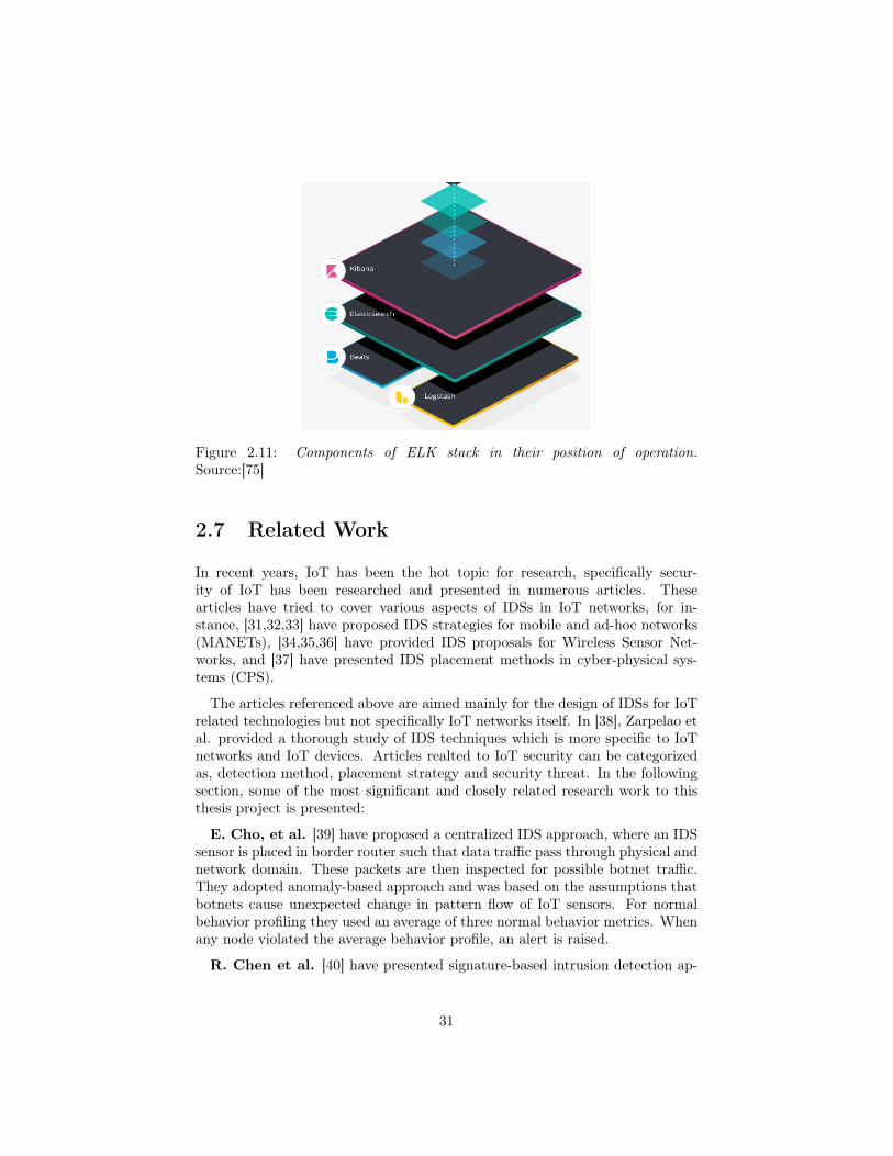
Figure 2.11: Components of ELK stack in their position of operation.Source:[75]
2.7 Related Work
In recent years, IoT has been the hot topic for research, specifically secur-ity of IoT has been researched and presented in numerous articles. Thesearticles have tried to cover various aspects of IDSs in IoT networks, for in-stance, [31,32,33] have proposed IDS strategies for mobile and ad-hoc networks(MANETs), [34,35,36] have provided IDS proposals for Wireless Sensor Net-works, and [37] have presented IDS placement methods in cyber-physical sys-tems (CPS).
The articles referenced above are aimed mainly for the design of IDSs for IoTrelated technologies but not specifically IoT networks itself. In [38], Zarpelao etal. provided a thorough study of IDS techniques which is more specific to IoTnetworks and IoT devices. Articles realted to IoT security can be categorizedas, detection method, placement strategy and security threat. In the followingsection, some of the most significant and closely related research work to thisthesis project is presented:
E. Cho, et al. [39] have proposed a centralized IDS approach, where an IDSsensor is placed in border router such that data traffic pass through physical andnetwork domain. These packets are then inspected for possible botnet traffic.They adopted anomaly-based approach and was based on the assumptions thatbotnets cause unexpected change in pattern flow of IoT sensors. For normalbehavior profiling they used an average of three normal behavior metrics. Whenany node violated the average behavior profile, an alert is raised.
R. Chen et al. [40] have presented signature-based intrusion detection ap-
31

proach which is based on artificial immune system mechanisms. They deployedsensors with information of attack signatures, referred as immune cells. Thesecells are said to be able to classify datagrams as malicious or normal. However,their paper does not provide any information about the placement strategyneither it concerns that how this method is feasible for a resource constraintIoT network. Collecting data for artificial immune cells can be a computationaland resource overhead.
Raza et al. [41] proposed an IDS solution for IoT named SVELTE. Thesolution is aimed for specific types of attack against IoT networks i.e. sinkholeand selective forwarding attacks. There method deploys a hybrid placementstrategy where border router and network nodes are involved in attack detection.Boarder router is responsible for detecting intrusion by analyzing RPL networkdata, while network nodes are programmed to send information to the borderrouter, reporting any malicious traffic and sending RPL network data. It alsoadopts hybrid approach in detection methods i.e. anomaly-based and signature-based to balance computational cost and storage cost respectively.
Lee et al. [42] published about a lightweight IDS system for IoTs. The paperadopts a distributed placement strategy which monitors energy consumption ofnodes for detecting intrusion, i.e. if energy consumption is above a normalthreshold an alert is raised. This is said to be useful against Dos attacks or ifa node is a part of a botnet. Moreover, a node is classified as malicious if itconsumes above the normal threshold energy and is removed from the routingtable. Authors used anomaly-based approach to analyze node behavior by en-ergy consumption. Since their method focuses only on a single node parameteri.e. energy consumption, less computational overhead is expected.
Cervantes et al. [43] proposed an IDS solution for IoT named INTI (In-trusion detection of Sinkhole attacks in 6LoWPAN for Internet of Things). Intheir method, nodes are placed in a hierarchal structure leading to a distributedplacement strategy. Each node in the hierarchy is assigned a role, where a super-ior node is monitored for its traffic patterns. It combines the specification-basedmethod by utilizing trust and reputation of nodes and anomaly-based methodto monitor exchange of packets between nodes. If, in case, a node detects asinkhole attack, it broadcasts a message to alert the other nodes.
A. Le et al. [44], presented a lightweight IDS solution for IoTs. Theyadopted a hybrid strategy by dividing the network into small clusters. Eachcluster is assigned a cluster head which is responsible for communicating withall cluster members. Cluster head is installed with an IDS sensor and it monitorsall of its cluster members, while member report only to their respective clusterhead. Border router is also installed with an IDS sensor and is responsible formore resource consuming instances. The authors adopted specification-basedapproach for detection of routing attacks.
Knowledge-driven Adaptable Lightweight Intrusion Detection System (Kalis),is an IDS approach presented by Midi et al. [45]. Kalis can be deployed on
32

border router or on an external device as a standalone tool. It uses a centralizedplacement approach. While in detection approach, it is hybrid in nature, suchthat it is self-adapting knowledge-driven IoT intrusion detection system whichcan work on different communication protocols.
Kalis is said to be autonomous in collecting information about network fea-tures and its involved components. Then using this information, Kalis dynamic-ally configures the most effective set of detection techniques. It can be extendedfor new protocols standards while the collected information can be shared forcollaborative detection. Compared to traditional IDS, authors claim that theirsystem is capable of detecting DoS, routing and conventional attacks.
A. Sforzin et al. [46] presented an IDS solution for IoTs using RaspberryPi and Snort. Their system is aimed for scalability, robustness, ease of useand versatility. It is claimed to be an effectively portable on demand IDS thatnotifies the users or the administrators of the network. Whenever it detects anongoing attack or suspicious network activities.
They adopted a centralized approach where RPi acts as a border router whileinstalled with snort sensor. All alerts can then be directed to remote serverrunning a Security and event Management software (SIEM). To check resourceconsumption of Snort, they used different rule sets of snorts, so that only themost relevant rules to IoT could be loaded. Authors conclude that their systemis not well suited for higher data rates and larger networks.
Table 2.3 summarizes some of the major efforts in IoT-IDS applications.
Research Placement approach Detection method Threat
E. Cho, et al. [39] Centralized Anomaly-based Botnet
R. Chen et al. [40] Hybrid Spicification-based Routing attacks
Raza et al. [41] Hybrid Hybrid Routing attacks
Lee et al. [42] Distributed Anomaly-based DoS
Cervantes et al. [43] Distributed Hybrid Routing attacks
A. Le et al. [44] Hybrid Specification-based Routing attacks
Midi et al. [45] Centralized Hybrid Conventional attacks
A. Sforzin et al. [46] Centralized Signature-based Conventional attacks
Table 2.3: A summary of the major research IoT area with concerned threatsand detection methods.
33

Chapter 3
Methodology
This chapter outlines approaches and steps towards building an intrusion de-tection system using affordable and portable hardware i.e. Raspberry Pi andopen source intrusion detection system (IDS) Snort. In first phase, this chapterwill explain intrusion detection design methodologies, system design and it’scomponents. While in next phase, adopted Snort algorithms will be presented.
3.1 IDS Design Methodology
It is very important to be vigilant while selecting IDS strategy. Specially, whendealing with a resource constrained environment, for example, in an IoT scen-ario. Typical IDS methodology consist of intrusion detection method, IDS place-ment approach, target attacks and validation method. This thesis adopted fol-lowing IDS methods:
i) Detection Method - A typical intrusion detection method can be signature-based, anomaly-based, specification-based or a hybrid of these methods.Since Snort uses it’s rule database to inspect and match pre-defined signa-tures of traffic, this thesis adopted signature based detection method.
ii) IDS Placement Approach - The thesis adopted centralized placementapproach, Snort was placed in Raspberry Pi gateway. All the connectedIoT devices or sensors were connected to internet through the gateway’saccess point only.
iii) Targeted Attacks - Conventional attacks hold a much larger bucket ofattacks vectors, ranging from DoS, bots, scanners, malwares etc. these arethe attacks which are more frequent and devastating.
34

This thesis was mainly concerning with conventional attacks, with a focuson DoS, detecting botnet traffic, alerting against scanners and recognizingssh dictionary attacks. A custom snort rule file was developed for each ofthe interface i.e. eth0 and wlan0.
3.2 System Design
The system was designed to keep in view the complications of IoT environment.Since IoT devices are wireless and have a broadcast signaling nature, it is relat-ively complicated to design a stand alone security mechanism for IoT devices.For test purposes, several assumptions were to be made, for instance, assumingthat only certain kind of IoT devices with same protocols are used e.g. sensorswith Message Queuing Telemetry Transport (MQTT).
Figure 3.1 shows the system design architecture. It gives an abstract ideaof how the system components were connected to each other. It also showsposition of intrusion detection device and how the attack machine and remoteELK (Elasticsearch, Logstash, Kibana) server were connected.
Figure 3.1: Adopted system design with it’s components and connection points.
3.2.1 System Components
As it can be seen from previous chapters, this thesis used empirical approach(using physical systems and not simulations) to deploy and test the systemcomponents. Some of the core components of the setup are explained in thefollowing section.
35

3.2.1.1 RPi Snort Gateway
Raspberry Pi 3 model B+ was used as a core gateway equipped with Snortsensor. Integrated Wi-Fi of RPi was used as hotspot to connect remote sensors.For operating system, Raspbian stretch 9.4 was installed. Table 3.1 shows detailsabout Raspberry Pi, used as a gateway Snort sensor.
Spec Raspberry Pi 3 B+CPU type/speed ARM Cortex-A53 1.4GHz
RAM 1GB SRAMEthernet speed 300Mbps
Operating System Raspbian stretch 9.4Snort Version 2.9.12 IDS mode
Table 3.1: Specification details of RPi device used as an IDS.
Snort version 2.9.12 was used as stand alone intrusion detection system. Itwas further customized to meet the resource constrained environment of RPigateway. It’s customization details are provided in chapter four. Moreover,Snort was configured to operate in IDS mode.
3.2.1.2 Sensors
An another RPi was used to attach sensors with. This was a Raspberry Pi modelB+ with Raspbian lite operating system. It was isolated and deployed at fairlydistant location. Moreover, it was connected to RPi Snort sensor gateway’saccess point by using integrated Wi-Fi module.
3.2.1.3 Router
It is very important to isolate Snort Gateway and attack machines from eachother and to make the attacks realistic as well as controllable. For this purpose,all the deployed systems were placed in different networks through static networkconfiguration. It was accomplished by using MikroTik hEX router series. Thissmall and cheap router provides five 100/1000 Ethernet ports which can provideup to a Gigabit throughput.
3.2.1.4 IDS Test Machine
Kali Linux [74] was chosen as operating system for IDS testing due to its built-inpenetrating testing packages. It is one of the most sophisticated Linux distro
36

which provides hundreds of test options for digital forensics and testing capab-ility of any security setup. It was installed on a HP core i5 laptop. Table 3.2shows some of the important specification of IDS testing machine.
Spec valueCPU type/speed Intel Core i5-3210M [email protected] x 4
RAM 8GBEthernet speed 1000Mb/s
Operating System Kali Rolling 2018.4 64 bit
Table 3.2: Specification details of IDS testing machine i.e. attacking machine
3.2.1.5 Remote Monitoring Server
Monitoring server was setup on Openstack cloud. It is an Ubuntu LTS machineloaded with Logstash, Elasticsearch, and Kibana (ELK stack). For secure re-mote access to Kibana dashboard, Nginx reverse proxy was placed. It can beaccessed from anywhere after provision of correct username and password.
3.3 Snort Algorithms
Snort is a single threaded pattern matching intrusion detection system whichrelies merely on Aho-Corasick [66] multi-pattern matching algorithm. Aho-Corasick is a backbone of Snort search and detection mechanism. Several vari-ants of this algorithm are available to be used in Snort, where each has it’sstrengths and weaknesses as well as each one has a significant impact on per-formance and resource utilization. In next section, Aho-Corasick (AC) is intro-duced briefly.
3.3.1 Aho-Corasick State Machine
The original AC algorithm was first presented by Alfred V. Aho and MargaretJ.Corasick (Aho et al.) in 1975 [66]. It was designed to locate all occurrencesof any of a finite number of keywords in a string of text. It is based on theconstruction of a finite state pattern matching machine from the keywords andthen use this pattern matching machine to process the text string in a singlepass.
For example, lets K = {y1, y2, ....yk} be a finite set of strings called keywordswhile lets x be an arbitrary string called text string, Then purpose of statemachine is to locate and identify all sub-strings of x which are keywords in
37
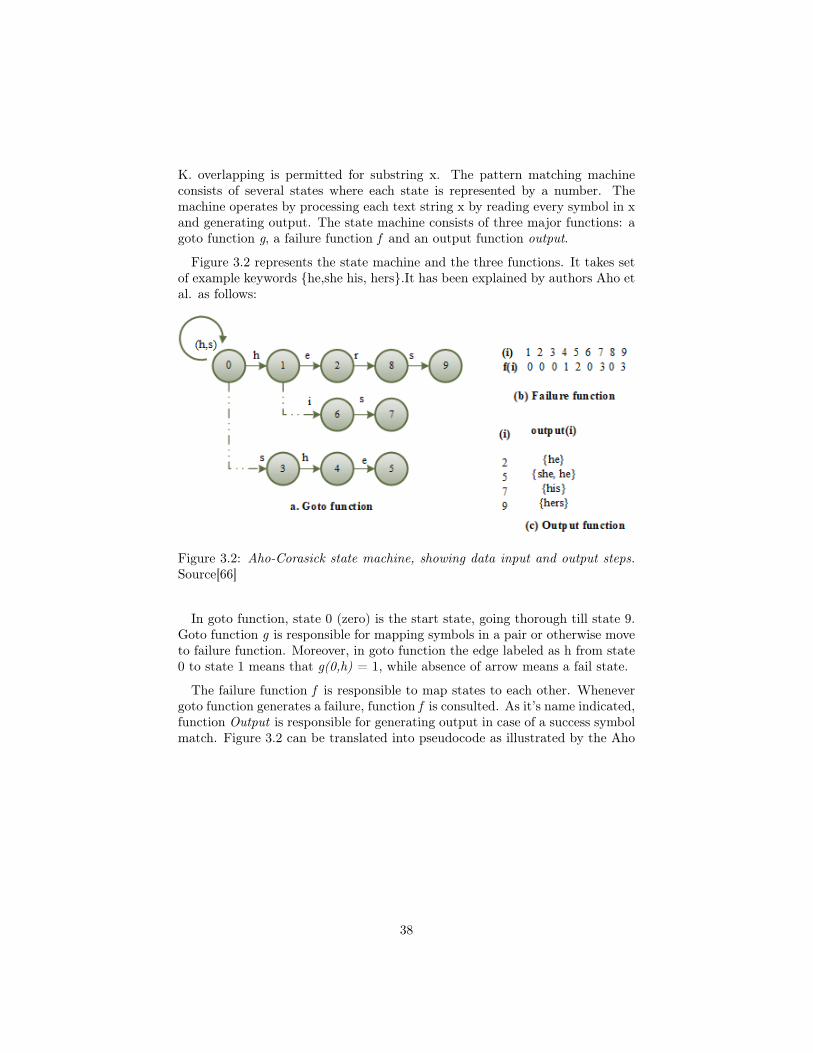
K. overlapping is permitted for substring x. The pattern matching machineconsists of several states where each state is represented by a number. Themachine operates by processing each text string x by reading every symbol in xand generating output. The state machine consists of three major functions: agoto function g, a failure function f and an output function output.
Figure 3.2 represents the state machine and the three functions. It takes setof example keywords {he,she his, hers}.It has been explained by authors Aho etal. as follows:
Figure 3.2: Aho-Corasick state machine, showing data input and output steps.Source[66]
In goto function, state 0 (zero) is the start state, going thorough till state 9.Goto function g is responsible for mapping symbols in a pair or otherwise moveto failure function. Moreover, in goto function the edge labeled as h from state0 to state 1 means that g(0,h) = 1, while absence of arrow means a fail state.
The failure function f is responsible to map states to each other. Whenevergoto function generates a failure, function f is consulted. As it’s name indicated,function Output is responsible for generating output in case of a success symbolmatch. Figure 3.2 can be translated into pseudocode as illustrated by the Aho
38

et al., pseudocode is given in below section.
Algorithm 1: Aho-Corasick pattern matching machine1 Input. Any text string consisting of input symbols, e.g. x = a1a2.....an.
where ai is an input symbol. And a pattern matching machine M withgoto function g, failure function f and an output function output.
2 Output. Location of keyword x.3 begin4 state←05 for i←1 until n do6 begin7 while g(state, ai) = fail do state←f (state)8 state←g(state, ai)9 if output(state) 6= empty then
10 begin11 print i12 print output(state)13 end14 end15 end
The failure transitions can be removed by Algorithm 1 by introducing func-tions of deterministic finite automate (DFA) in-place of goto and failure func-tions.
When an input character stream is provided, a DFA requires only one trans-ition of the state machine to locate the correct next state. It consists of a finiteset of states S, a next move function δ, where for each state s, and input symbola, δ(s, a) is a state in S.
In Algorithm 1, the DFA next move function δ can be used instead gotofunction. For instance, this can be done by replacing first two statements infor-loop by a single statement state ← δ(state, ai). Aho et al. have presentedthe DFA version of AC algorithm as given in Algorithm 2. They concludedthat amount of memory required to store δ in Algorithm 2 is higher than thecorresponding goto function. Whereas using DFA in Algorithm 1 can reducenumber of state transitions to as low as 50% of total state transition in originalimplementation.
Snort implements optimized version of Aho-Corasick. There are several vari-ants available to choose from. Each of the variant has it’s own performance andmemory trade-offs. The optimized version uses state transition table, which is alist of pointers to the state vectors. Where each state vector represents a validstate transition. Moreover, each state vector includes a header and a Booleanflag, indicating storage format of the row and occurrence of pattern matchingrespectively.
39

There has been an extensive research on improvement of Aho-Corasick forSnort, to improve match speed as well as to minimize memory usage.
Algorithm 2: DFA version of AC algorithm16 begin17 queue←empty18 for each symbol a do19 begin20 δ(0, a)←g(0, a)21 if g(0, a) 6= 0 then queue←queue ∪ {g(0, a)}22 end23 while queue 6= empty do24 begin25 let r be the next state in queue26 queue←queue - {r}27 for each symbol a do28 if g(r, a) = s 6= fail do29 begin30 queue←queue ∪ {s}31 δ(r, a)←s32 end33 else δ(r, a)← δ(f(r), a)34 end35 end
3.3.2 Snort Implementation of AC
Snort team leader Marc Norton in [67], tested and analyzed the optimized ver-sion of AC algorithm in Snort with it’s different variants, where he found signi-ficant performance and memory usage differences. As compared to the originalversion, optimized version handles the state table differently i.e. it breaks thestate table into transition tables, where each contains a pattern matching listand a separate failure pointer list, which improved both memory usage as wellas match speed. Optimized AC algorithm can be presented in a simple code asgiven in the Listing 3.1.
The NextState in Listing 3.1, is an array of pointers to the row vectors of thestate table, while ps points to the current state’s transition vector. The firsttwo words in array ps represent storage format and boolean match flag. Theparameter T is the input text being searched, while xlatcase is case converterwhich converts the text to uppercase on byte at a time. It is used in caseindependent scenarios. When a match is found, the pattern is processed. Toverify that a pattern has been successfully matched, if(ps[1]) is used as a checkstatement. In case of no match, control sequences moves to the next state, whilein case of a match, all the patterns in current state are processed in for loop.
40
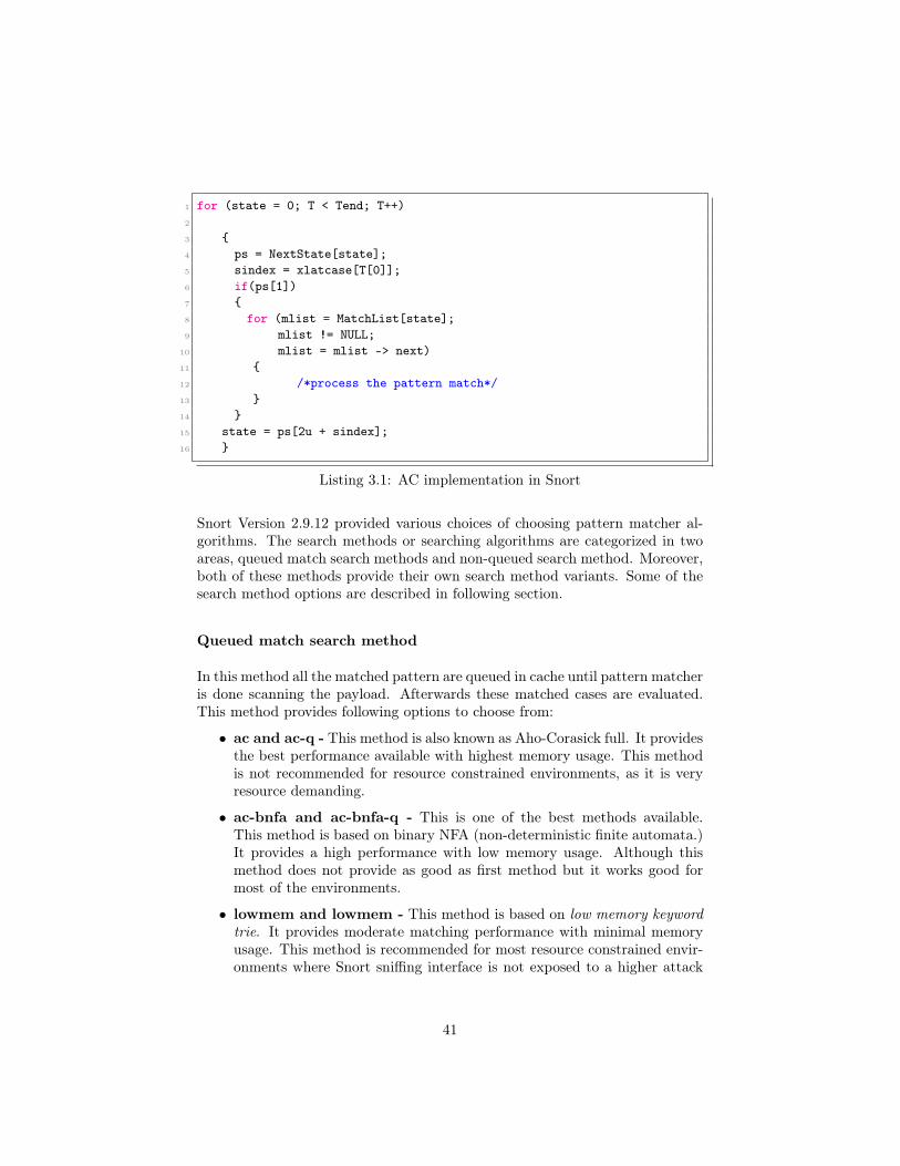
1 for (state = 0; T < Tend; T++)2
3 {4 ps = NextState[state];5 sindex = xlatcase[T[0]];6 if(ps[1])7 {8 for (mlist = MatchList[state];9 mlist != NULL;
10 mlist = mlist -> next)11 {12 /*process the pattern match*/13 }14 }15 state = ps[2u + sindex];16 }
Listing 3.1: AC implementation in Snort
Snort Version 2.9.12 provided various choices of choosing pattern matcher al-gorithms. The search methods or searching algorithms are categorized in twoareas, queued match search methods and non-queued search method. Moreover,both of these methods provide their own search method variants. Some of thesearch method options are described in following section.
Queued match search method
In this method all the matched pattern are queued in cache until pattern matcheris done scanning the payload. Afterwards these matched cases are evaluated.This method provides following options to choose from:
• ac and ac-q - This method is also known as Aho-Corasick full. It providesthe best performance available with highest memory usage. This methodis not recommended for resource constrained environments, as it is veryresource demanding.
• ac-bnfa and ac-bnfa-q - This is one of the best methods available.This method is based on binary NFA (non-deterministic finite automata.)It provides a high performance with low memory usage. Although thismethod does not provide as good as first method but it works good formost of the environments.
• lowmem and lowmem - This method is based on low memory keywordtrie. It provides moderate matching performance with minimal memoryusage. This method is recommended for most resource constrained envir-onments where Snort sniffing interface is not exposed to a higher attack
41

vector i.e. towards internet but is exposed to only limited attack vectorse.g. an access point exposed to a limited connectivity area.
• ac-split - This is the default pattern matcher algorithm implemented inSnort version 2.9.12. It provides a high matching performance with lowmemory usage. Compared to ac-bnafa-q, it consumes more memory. Snortrecommends this method for most of the machines. This method is knownalso as split-any-any.
Non-queue search method
In this method, as it’s name indicates, all the patterns are processed individuallywithout queuing in cache. nq option specifies that matches should not be queuedand evaluated as they are found. It provides following pattern matcher options:
• ac-nq - This method is same as ac-q but without queuing. It providesbest performance with high memory usage.
• ac-bnfa-nq - In previous versions of Snort, this was the default searchmethod. It provides high performance with low memory usage withoutqueuing.
• lowmem-nq - It is same as lowmem-q without queuing capability.
Default installation of Snort is not recommended, specially while dealing withresource constraint scenarios. This thesis has implemented Snort in an IoTenvironment on a relatively low spec device i.e. Raspberry Pi. Snort is cus-tomized with several configurations to match the hardware components capab-ility without sacrificing performance and memory utilization. Chapter four willprovide the Snort configuration details.
3.3.3 Detection and Processing of Rules
Snort was functioning in IDS mode. Detection and rule processing phase ishighly resource consuming because of pattern matcher algorithms. For ex-ample, in case of syn flooding attack, Snort first sniffs the packet, sends itto detection engine, which processes the rule with pattern matcher algorithmwhich inspects packet payload and header information and matches it withboth the rule option and rule header i.e. it looks for Source and destinationIPs and ports in rule header. Next, it looks for rule options, for instance, ifSYN flag (S) is set, and the interface received more than 20 packets with flagS within thirty second time period, match is successful. Snort detection en-gine then passes the packet to output module which takes further configuredaction. Algorithm 3 shows how a SYN flooding rule is processed by Snort.
42

Algorithm 3: SYN flooding rule processed by Snort1 Input. Acquired traffic packets during sniffing.2 Output. Configured action, alert, log, drop.3 Start4 load config-file5 Initialize6 {7 output plugins;8 pre-processors;9 plugins;
10 rule files;11 }12 begin13 {14 packet acquisition;15 packet processing;16 }17 Case: (rule matching; instance: detection engine)18 for s in packet do: # s is any string in packet19 {20 if21 {22 source ip == $EXTERNAL_NET;23 port == $PORT;24 flags == S;25 packet count == 20;26 time == 30 seconds;27 }28 do:29 {30 generate alert;31 }32 else:33 {34 ignore;35 commence next packet;36 }37 end38 }39 end
43

3.4 The Approach
In this thesis project, system components were chosen and configured carefullyto avoid unnecessary IoT environmental factors which can effect system testresults. Several conditions were placed to avoid factors which can negativelyinfluence test results.
3.4.1 Conditions
The conditions regarding components connectivity and attack scenarios aregiven as follows:
• All the sensors were connected to the RPi gateway access point only andthere was no other connectivity point for the sensors. Also, sensors wereconfigured with static IP addresses. For internet connectivity, RPi gate-way was the only route available to all the sensors.
• All the senors were of same type and were configured over another Rasp-berry Pi. MQTT was the only telemetry protocol which had been imple-mented for gateway-sensor communication. SSH was also enabled betweengateway and the sensors (via another RPi).
• RPi gateway was not exposed to the internet. Instead, it was connectedto MikroTik router. This step was taken to avoid unnecessary traffic frominternet, which can influence test results negatively.
• It is literally impossible to test all possible attack vectors. Only few ofthe major and more common attacks were chosen for system testing, e.g.DoS, SSH dictionary attacks and port scanners.
3.4.2 Attack scenarios
There were two possible attack points on RPi gateway, i.e. interface eth0 andwlan0. The eth0 interface provided internet connectivity through the routerwhile wlan0 acted as an access point and provided connectivity to the sensorsin WiFi range. Both of the interfaces had different attack vectors because eachinterface was exposed to different attack spectrum. For instance, eth0 was proneto a larger attack vector than wlan0 as it was exposed towards internet. Oncontrary, wlan0 had a smaller exposure area for direct attacks i.e. WiFi signalrange.
Keeping this phenomenon in view, two instances of Snort were running, oneon each interface. Each Snort instance was provided with different rule filesaccording to their attack vectors, i.e. eth0 needs more rules than wlan0. Also,both of the instances were using different pattern matching algorithms.
44
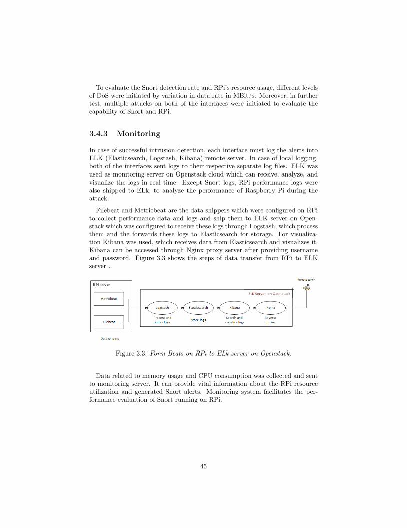
To evaluate the Snort detection rate and RPi’s resource usage, different levelsof DoS were initiated by variation in data rate in MBit/s. Moreover, in furthertest, multiple attacks on both of the interfaces were initiated to evaluate thecapability of Snort and RPi.
3.4.3 Monitoring
In case of successful intrusion detection, each interface must log the alerts intoELK (Elasticsearch, Logstash, Kibana) remote server. In case of local logging,both of the interfaces sent logs to their respective separate log files. ELK wasused as monitoring server on Openstack cloud which can receive, analyze, andvisualize the logs in real time. Except Snort logs, RPi performance logs werealso shipped to ELk, to analyze the performance of Raspberry Pi during theattack.
Filebeat and Metricbeat are the data shippers which were configured on RPito collect performance data and logs and ship them to ELK server on Open-stack which was configured to receive these logs through Logstash, which processthem and the forwards these logs to Elasticsearch for storage. For visualiza-tion Kibana was used, which receives data from Elasticsearch and visualizes it.Kibana can be accessed through Nginx proxy server after providing usernameand password. Figure 3.3 shows the steps of data transfer from RPi to ELKserver .
Figure 3.3: Form Beats on RPi to ELk server on Openstack.
Data related to memory usage and CPU consumption was collected and sentto monitoring server. It can provide vital information about the RPi resourceutilization and generated Snort alerts. Monitoring system facilitates the per-formance evaluation of Snort running on RPi.
45
Chapter 4
Implementation
This chapter guides through the process of implementing system design. Itprovides details about Snort and Raspberry Pi configurations and system test-ing.
4.1 Compiling Snort on RPi
Installation of Snort in RPi device is relatively trickier because of Arm Linuxarchitecture dependencies. Due to these dependencies, several compilation er-rors can occur, to avoid such errors, it is better to compile Snort from source.It is recommended not to install Snort as root, instead use sudo on a non-rootuser base. Appendix A shows how Snort was configured on Raspberry Pi.
It is a good idea to disable all the default rule paths. Following sed commandcan be used to disable rule paths.sudo sed -i “s/include \$RULE\_PATH/#include \$RULE\_PATH/“ /etc/snort/snort.conf
4.2 Customizing Snort
If Snort is installed with default configurations and with default rule sets, it caneasily overwhelm even a powerful server. For example, there are several opensource portals which provide ready to use Snort rules. e.g. EmergingThreat[69],Talos[70] and Snort community-rules[71]. Collectively, these portals provide15 to 20 thousand rules, which are updated with new rules almost everyday.When these rules are loaded into memory and Snort starts to process themwith patter matcher algorithm (assume ac-split Snort default) one by one fora potential match, it can apparently claim a large memory chunk, letting thesystem paralyzed for processing other crucial system tasks.
46

This thesis configured Snort for RPi with selected rules and ac-bnfa-nq al-gorithm. Figure 4.1 gives an abstract idea of how Snort was configured andwhat areas of Snort were tweaked and tuned for RPi. The following sectionprovides further details of Figure 4.1.
Figure 4.1: Shows how the Snort is configured on RPi with two Snort instancesand Beats
4.3 Snort Instances
Two instances of Snort were running, one was sniffing over eth0 interface whileanother on wlan0 interface. It may sound unreasonable to run two instancesof Snort on a low spec device such as RPi but the major issue is that Snort issingle threaded which means in IDS mode it can only sniff a single instance at agiven time, for sniffing on multiple interface, multiple Snort instances must beused, one for each interface.
Both of the instances were loaded with separate configuration files and rulesets. Snort instances can be run either on separate terminals or as a daemon.To run Snort as daemon, for instance on eth0, type the command as follows:
sudo snort -d -c /etc/snort/snort.conf -l /var/log/snort -D -i eth0
The -D switch runs Snort as a background process while -l instructs Snort tostart logging to the specified directory. Snort background instance can be killed
47

by ps -eaf | grep snort and then pkill -9 PID (Snort PID). Following sectionfurther explains how Snort eth0 instance was configured.
4.3.1 Snort Instance Eth0
Interface eth0 was responsible for provision of internet connectivity to wholenetwork. A snort instance was configured to run on interface eth0 with specificcustom configurations and rules. following sections provide details about eth0configurations.
4.3.1.1 Network
Using Mikrotek router, interface ethernet2 was configured for Raspberry Pinetwork 192.168.10.0/24 with subnet-mask 255.255.255.0 and default gatewayas 192.168.10.1. RPi’s eth0 was provided static ip address 192.168.10.20. Itis important to not that raspbian-stretch RPi OS does not support static ipconfigurations in directory / etc/network/interface, but picks static ip configur-ations from /etc/dhcpcd.conf file. Static configuration for eth0 can be seen inthe following code.
interface eth0static ip_address=192.168.10.20static routers=192.168.10.1static domain_name_servers= 8.8.8.8 192.168.10.1
Listing 4.1: Static ip configuration
No filtering or firewall was enabled on router to minimize test effecting data.
4.3.1.2 Snort Eth0 Configuration File
A separate Snort configuration file for interface eth0 was created and loaded witheth0 specific configurations. Appendix F shows the configurations of snort_eth0file for interface eth0. Enabling perfmonitor is optional, but it is a good idea toenable it, because it gives real time Snort performance metrics. These metricscan either be saved to an output file or to console. In Appendix F, pfmonitoris set to output data to console when Snort exits.
4.3.1.3 Eth0 Rules File
Since eth0 was connected to internet via router, it is highly likely that it wasexposed to a larger set of attack vector as compared to wlan0 so it requirescomparatively larger set of Snort detection rules. One quick method is to enable
48

all rules provided by Snort, Second method is to choose adoptive approach andselect environment specific rules only. For instance, no POP3 server was runningon RPi gateway so no POP3 rule were required.
Only those rules were enabled which are effective in detection of major at-tacks against IoTs, e.g. rules related to DoS, botnets, scanners, telnet, SSHbrute-forcing(dictionary attacks) malware patterns and few other. An approxof five thousand rules were selected for eth0. Some of the sample Eth0 rules arepresented in Appendix G.
4.3.2 Snort Instance Wlan0
Similar to eth0, interface wlan0 was loaded with separate Snort instance. Listing4.2 shows the configurations for config file snort_wlan0.conf.
1 #copy original snort.conf file2 Sudo cp /etc/snort/snort.conf snort_wlan0.conf3 sudo nano /etc/snort/snort_wlan0.conf4 #configurations start from here5 ipvar HOME_NET 192.168.42.0/246 ipvar EXTRNAL_NET !$HOME_NET7 var RULE_PATH /etc/snort/rules8 var SO_RULE_PATH /etc/snort/so_rules9 var PREPROC_RULE_PATH /etc/snort/preproc_rules
10 var WHITE_LIST_PATH /etc/snort/rules11 var BLACK_LIST_PATH /etc/snort/rules12 config pcre_match_limit: 350013 config pcre_match_limit_recursion: 150014 config detection: search-method lowmem search-optimize max-pattern-len 2015 preprocessor perfmonitor:16 time 300 events atexitonly max console pktcnt 100017 output log_tcpdump: /var/log/snort/eth0/snort.log18 include $RULE_PATH/wlan0.rules
Listing 4.2: snort_wlan0.conf
Unlike eth0 instance which was using ac-bnfa-nq pattern matcher algorithm,instance wlan0 was configured with lowmem algorithm. As it’s name indicates,it is a medium performance and low memory algorithm, which matches wlan0requirements.
4.3.2.1 Network
Interface wlan0 was running it’s own isc-dhcp-server with network 192.168.42.0/24and subnet 255.255.255.0. Since wlan0 was utilized as access point (AP) toprovide wireless connectivity to sensors, all the sensors obtained ip addressesfrom 192.168.42.0/24 ip-pool. In order to turn wlan0 WiFi into an AP, an open
49

source package hostapd was used. Appendix B shows configuration process ofisc-dhcp-server and hostapd on RPi.
4.3.2.2 Wlan0 Rules
Interface wlan0 was least susceptible to a larger attack vector, the reason isthat it is less exposed to direct attacks on AP. If an attacks comes through theinternet i.e. through interface eth0, Snort eth0 instance will already detect it.Some of the direct attacks on AP might not be detected by Snort because itis not able to sniff or commence the packets. For instance, evil twin and de-authentication attacks can not detected by Snort, to detect such attacks othertools like Kismet[72] can be used, which is out of the scope of this thesis project.
Considering above discussed phenomenon, a relatively small set of rules wasselected for wlan0 Snort instance. A sample rule can be as follows:
#rule for botnet C2C flowalert tcp any any -> any 23 (msg:"Mirai C2C flow, inbound login attempt";
flow:to_server,established; content:"xc3511";depth:6; sid:1000000;rev:1)
4.3.3 Logging
Both of the Snort instances were set to log to their own logging directories, i.e.instance eth0 logs to directory /var/log/snort/eth0/ while instance wlan0 logsto /var/log/snort/wlan0 directory. These loggs were shipped to ELK serverusing Beats data shippers. Following section provides details of how Beats wereconfigured on RPi.
4.4 Configuring Beats on RPi
Filebeat and Metricbeat are the important component of Beats package. Theyinclude internal modules that simplify collecting, parsing and visualizing com-mon log formats such as, NGINX, Apache and system metrics. It is recommen-ded not to install Go, which is the language Beats are written in, by apt-getwhich at the time of writing this thesis, does not compile on RPi with Raspbianstretch and generates errors.
A stable Arm release of Go was installed from official Go repository[73]. Ap-pendix C shows the process of installing Go and Beats on Rpi. To setup Filebeatand enable system module, ./filebeat modules system enable was used, while toship data to ELK server, ./filebeat -e was used. Similar is the process of usingMetricbeat.
50

4.5 Configuring ELk server
ELK server was setup on Openstack cloud where it was enabled to receive logsand RPi performance data including, CPU, memory, system load and networkinformation. Kibana dashboard can be access remotely by https://ElK-Server-IP and providing username and password. It is important to open port 5044 onOpenstack, it can be done by: Access & security > Manage Rules > Add Rule> port 5044. Appendix D provides script of how to install and configure all thenecessary components of ELK stack as well as Logstash filters for parsing Snortalerts. It is recommended to install older stable JDK version (Java version 8.1is a good option), as by date of this thesis writing, Logstash version 6.3 was notcompatible with latest Java distribution.
4.6 Testing
To evaluate the performance of RPi and Snort, different rates of syn-flood at-tacks in terms of MBit/sec were initiated from IDS testing machine with Kali.Test Data rates were 100MBit/sec, 300MBit/sec, and 500MBit/sec. A bashscript was written and run on RPi which can automatically start both of theSnort instances at interfaces eth0 and wlan0 and stop them after time intervalof 600 seconds. The script can start Filebeat and Metricbeat as well in the sametime-frame, same script also monitored RPi resource consumption and gener-ated the graph depicting RPi’s CPU and memory status during the attacks.
An another script was started on IDS test machine (attack machine) whichinitiated syn-flood attacks at different data rates for each test individually. Thepurpose of testing was to accomplish objective (b) of problem statement, i.e.Does RPi have enough resources to support Snort as an IDS, in terms of resourceconsumption? In order to test RPi capability of hosting Snort as an IDS,interface eth0 was tested first at multiple attack data rates. Interface eth0was attacked by syn-flood while wlan0 was attacked by ssh-dictionary attack(ssh brute-force) from one of the compromised sensors (another RPi used assensor) connected to RPi’s access point.
Interface eth0 with Snort instance_eth0 was tested individually, in final test,both of the interfaces were attacked at the same time to test the worst casescenario. Figure 4.2 shows the attack points on RPi gateway, as well as theSnort instances responsible to detect these attacks.
51

Figure 4.2: Figure created from system design figure, it shows attack vectors oneach interface
4.6.1 Test 1
The first test was to syn-flood interface eth0 at 100MBit/sec data rate fromattack machine. Interface eth0 of RPi can facilitate a maximum of 300MBit/secof bandwidth. The purpose of this test was to evaluate the performance of RPiwhile it is under attack and Snort IDS and Beats are running. Table 4.1 showsthe characteristics of Test 1.
Parameter ValueAttack Data Rate 100MBit/sec
Attack Type Syn-floodNumber of Rules ≈7000
Interface under Attack Eth0Run Time 600 SecondsInstances Eth0, wlan0 and Beats
Table 4.1: Characteristics of Test 1, syn-flood at 100MBit/sec
Test 1 was run for 600 seconds with a total rule set of 7000 rules, where6000 rules were assigned to Snort instance eth0 and an approx of 1000 ruleswere provided to wlan0. It is important to note that Snort instance wlan0 wasrunning but was not under attack in any next tests except test 4. To load Snortinstances and Beats, the script in appendix E was run with bash snort.sh whileat the same time syn-flood attack from attack machine was initiated by hping3command:
52

hping3 -d 0 -S -p 80 --flood --rand-source 192.168.10.20
The hping3 flooded the interface eth0 of RPi with packets set with syn flags(-S option) with random source ip addresses. -d 0 option sets data payload to 0while option -p 80 sets the target port to port 80. This Command can generatean approx data rate of ≈100MBit/sec.
4.6.2 Test 2
Test 2 differs from Test 1 by a change in attack data rate from attack machine.For test 2, attack data rate was set to 300MBit/sec. The purpose of this attackwas to analyze full capability of interface eth0 and make RPi CPU to work onmore packets. i.e. interface eth0 responds with an ack to each syn packet,resulting in an increased CPU consumption, also, Snort has to commence andprocess more packets per seconds which also increases CPU usage. Test 2 char-acteristics are provided in Table 4.2.
Parameter ValueAttack Data Rate 300MBit/sec
Attack Type Syn-floodNumber of Rules ≈7000
Interface under Attack Eth0Run Time 600 SecondsInstances Eth0, wlan0 and Beats
Table 4.2: Test 2 characteristics and it’s values for a higher data rate of300MBit/sec
The hping3 command used to generate syn flood on 300MBit/sec data rateis given as:
hping3 -d 120 -S -p 80 --flood --rand-source 192.168.10.20
All the other parameters of above hping3 command remained the same astest 1, except the packet payload size i.e. option -d 120, which makes hping3to send each syn packet with a packet payload size of 120 bytes. Hping3 notonly increases the packet size but also increases the packets/sec rate to maintainthe maximum flood rate. Test 2 sent syn packets at the rate of ≈300MBit/secwhich matches the maximum supported rate of Ethernet interface eth0 of RPi.
53

4.6.3 Test 3
Test 3 was meant to increase the CPU clock rate of RPi by flooding ICMP type 3code 3 packets, destination unreachable and port unreachable respectively. Thistype of attack is referred as BlackNurse. This attack is notorious for very highCPU consumption even at low rate of only ≈130MBit/sec. There are severalsystems which are vulnerable to this kind of attack. By using even a singlelaptop, this attack can shutdown a vulnerable server by over-loading the CPU.Table 4.3 gives details of test 3 characteristics in the following:
Parameter ValueAttack Data Rate 130MBit/sec
Attack Type BlackNurseNumber of Rules ≈7000
Interface under Attack Eth0Run Time 600 SecondsInstances Eth0, wlan0 and Beats
Table 4.3: Test 3 characteristics while it used BlackNurse attack at relativelylow data rate
Following command can be used to initiate this attack:
hping3 -1 -C 3 -K 3 --flood --rand-source 192.168.10.20
In the command above, switch -1 sets attack mode to ICMP, -C 3 selectscode 3 of ICMP (destination unreachable), -k 3 sets type of ICMP to type 3(port unreachable).
4.6.4 Test 4
Test 4 attacked both of the interfaces at the same time, i.e. interface eth0 andwireless interface wlan0. The purpose of this test was to evaluate the worstcase scenario of RPi as an IDS machine. Worst case scenario in the sense thatit is less likely that both of the interfaces could be attacked at the same time.This was the test where both of the Snort instances were detecting the attacks,generating alerts and writing logs to their respective logging directories.
From attacker machine, same syn-flood attack was initiated against eth0 atthe data rate of 300MBit/sec, while interface wlan0 was attacked by a comprom-ised sensor already connected to RPi’s access point. For interface wlan0 attack,it was assumed that the compromised sensor (another RPi) was trying to loginto the RPi gateway through ssh brute-force (Dictionary attack). The Dictionaryattack is a low rate attack which requires data rate of ≈10-30KBit/sec.
54

The ssh dictionary attack uses a dictionary of usernames and passwords tologin to a system. If any username and password matches, attack is successful.The aim to choose this attack was to simulate the real life behaviour of most ofthe botnet command and control servers, which use the same attack methods tocompromise machines with weak/default usernames and passwords. Table 4.4presents the details of attack characteristics selected for test 4.
Parameter Value for Eth0 Value for Wlan0Attack Data Rate 300MBit/sec 30KBit/sec
Attack Type Syn-flood ssh bruteforceNumber of Rules ≈6000 ≈1000
Interface under Attack Eth0 Wlan0Run Time 600 Seconds 600 SecondsInstances Eth0, Wlan0 and Beats Eth0, Wlan0 and Beats
Table 4.4: Test 4 characteristics. It shows a dual attack on both interfaces withdifferent data rates.
The hping3 command was used from attacker machine, while nrack was usedfrom compromised sensor to initiate ssh bruteforce. The attack commands aregiven as follows:
ncrack -p 22 --user root -P dark-web-top-10000.txt -T5 192.168.42.1hping3 -d 120 -S -p 80 --flood --rand-source 192.168.10.20
The hping3 command is same as in test 2. while in ncrack, option -p 22 setstarget port to port 22 (ssh port), option –user root sets target username to beprobed to root, option -P loads the file containing a dictionary of passwords,dark-web-top-10000.txt file in this case, option -T5 increases the prob rate to5 tries in a single prob, 192.168.42.1 is the target ip address i.e. gateway ip ofwlan0 access point. Test 4 was very important because it tested the decisionwhether it was sensible to run two Snort instances on a low spec device Rasp-berry Pi, also test 4 pushed the RPi capability to it’s limits. Results obtainedfrom each test as well as response of Beats and monitoring server are discussedin next chapter i.e. chapter 5 Analysis.
55

Chapter 5
Results and Analysis
This chapter provides an analysis of all the conducted tests of Raspberry Pi andSnort as an IDS. This chapter evaluates the results in connection to one of thecore objectives of this thesis, i.e. Does RPi have enough resources to supportSnort as an IDS, in terms of resource consumption?
5.1 Test 1
Test 1 was taken to evaluate the RPi CPU and memory utilization during arelatively low rate syn-flood attack on 100MBit/sec. The focal point of all thetests was CPU consumption while memory was an added parameter becausemain memory consumer is the Snort rule set which stayed constant during allthe tests. The reason to add memory parameter into tests was to give anestimate that how much Snort can influence the RPi memory for a given set ofrules.
It is currently not possible to receive Snort overall statistics while Snort isrunning, the only way to get Snort statistics is to read Snort I/O summary afterit exits, therefore, Snort data was obtained when Snort stopped after the test i.e.precisely after 600 seconds. Snort was able to commence 3037094 packets, whereit analyzed a total of 225408 packets, marking success rate in terms of packetanalysis to be 7.42%. Snort dropped almost half of the packets i.e. 2811684with a percentage of 48.07%, it is worth mentioning that packets dropped bySnort should not be confused by the packets dropped by Ethernet interface, infact, packets dropped by Snort are the packets which are already passed by theinterface and commenced by Snort but Snort could not inspect them from thememory. Table 5.1 shows the details of Snort I/O values during the Test 1.
The largest portion of the packets were outstanding packets i.e. 2811686with a percentage of 92.578%. Outstanding packets are those packets which
56
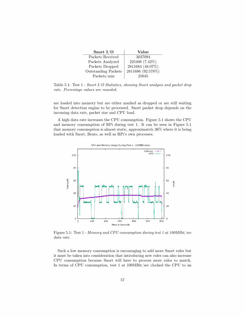
Snort I/O ValuePackets Received 3037094Packets Analyzed 225408 (7.42%)Packets Dropped 2811684 (48.07%)
Outstanding Packets 2811686 (92.578%)Packets/min 25045
Table 5.1: Test 1 - Snort I/O Statistics, showing Snort analysis and packet droprate. Percentage values are rounded.
are loaded into memory but are either marked as dropped or are still waitingfor Snort detection engine to be processed. Snort packet drop depends on theincoming data rate, packet size and CPU load.
A high data rate increases the CPU consumption. Figure 5.1 shows the CPUand memory consumption of RPi during test 1. It can be seen in Figure 5.1that memory consumption is almost static, approximately 36% where it is beingloaded with Snort, Beats, as well as RPi’s own processes.
Figure 5.1: Test 1 -Memory and CPU consumption during test 1 at 100MBit/secdata rate.
Such a low memory consumption is encouraging to add more Snort rules butit must be taken into consideration that introducing new rules can also increaseCPU consumption because Snort will have to process more rules to match.In terms of CPU consumption, test 1 at 100MBit/sec clocked the CPU to an
57

average of 56% of total CPU, at this percentage, RPi was able to perform it’soperations effortlessly without any performance lagging. During test 1, it hadbeen noticed that Metricbeat and Filebeat kept connecting and disconnectingto ELK server periodically, showing that on RPi, at even 100MBit/sec attackdata rate, some of the services can be disrupted, although ssh kept operational.
In Figure 5.1, certain fluctuations can be seen in CPU usage, one of the reasonsis that in test one, packet size was small with no data payload and Snort keptrefreshing it’s packet buffer whenever the buffer got overloaded, with each bufferrefresh, CPU usage dropped and then it gradually got higher til next bufferreload, this cycle continuous until Snort commences different size of packets.It is important to note that buffer refresh does not follow any particular timeinterval.
5.2 Test 2
Test 2 was conducted at higher attack data rate of 300MBit/sec with a largerpacket size of 120 bytes of data payload. Purpose of this attack was to eval-uate RPi response to a higher data rate syn-flood attack in terms of resourceconsumption, as well as to evaluate Snort performance. It is worth mentioningthat RPi model 3 B+ Ethernet interface can support a maximum of 300Mbpsof throughput, any data rate above that will be bottlenecked at eth0.
Snort was expected to commence more packets with a higher drop rate. Table5.1 shows the statistics of Snort after Test 2 was finished. Snort was able tocommence 4590679 packets, which is 33.8% higher than test 1.
Snort I/O ValuePackets Received 4590679Packets Analyzed 245358 (5.35%)Packets Dropped 4341882 (48.61%)
Outstanding Packets 4345321 (94.65%)Packets/min 27262
Table 5.2: Test 2 - Snort I/O Statistics, showing Snort analysis and packet droprate. Analysis rate has dropped while outstanding rate has increased.
Although it was expected that Snort will be commencing more packets in test2 but Snort did not go through each and every packet, most of the traffic waspassed and not analyzed which Snort does not count in I/O counters. Snortdropped 48.61% of packets which is not much different than test 1. Snort wasable to analyze only 5.35% of packets with 94.65% of outstanding rate.
Since packet size was larger in test 2, Snort spent more time on inspectingpackets which raised outstanding packet rate and dropped the packet analysis
58

rate, such behaviour of Snort should also be evident in terms of CPU consump-tion, i.e. it should be more consistent with less spontaneous fluctuations becausethere is less frequent buffer reloads by Snort for larger packets, as discussed intest 1. Figure 5.2 confirms this behaviour of Snort where CPU fluctuates veryclose to the average CPU consumption of 64.7% with less frequent changes.
Figure 5.2: Test 2 -Memory and CPU consumption during test 2 at 300MBit/secdata rate. CPU consumption is increased but consistent as compared to test 1.
There was a ≈15% increase in CPU consumption as compared to test 1, whichwas not as higher as it was expected according to data rate ratio. The memoryconsumption was almost the same as test 1 because no new Snort rules wereadded during test 2. A different attack type might increase or decrease memorybased on it’s rule class and number of associated rules. Test 3 will explain thisphenomenon.
During test 2, it was noticed that RPi’s monitoring service was down, both ofthe Beats were unable to connect to ELK server, unless the attack was stopped.It shows that a 300MBit/sec syn-flood attack can knock of most of RPi’s Eth-ernet associated services i.e. ssh was down and it was not possible to connectto RPi via ssh. Although with a 64.7% CPU usage, RPi was able to run it’sinternal services smoothly and no performance lag was noticed, RPi as an IDSwas able to perform fine during test 2 but without remote monitoring, whichmakes it less significant as a remotely operated IDS system.
During test 2, it was concluded that Ethernet interface of RPi with only300Mbps throughput support, can lead to failure of RPi as a remote IDS.
59

5.3 Test 3
Test 3 changed the attack type from syn-flood to ICMP flood attack calledBlackNurse. This attack was meant to assess RPi’s vulnerability to this attackand to analyze CPU consumption. During test 3, Snort was able to detectthis attack and generate alerts. Compared to syn packets, Snort handles ICMPpackets more smoothly with higher analysis rate and comparatively lower droprate. Table 5.3 shows the results summary obtained from Snort after the attack.
Snort I/O ValuePackets Received 16675421Packets Analyzed 3532178 (21.18%)Packets Dropped 13131500 (44.05%)
Outstanding Packets 13143243 (78.82%)Packets/min 392464
Table 5.3: Test 3 - Snort I/O Statistics, showing Snort analysis and packet droprate during BlackNurse attack. A higher packet commence rate by Snort can benoticed.
It can be noticed in Table 5.3 that Snort was able to receive much morepackets than syn-flood, it is because Snort’s traffic pass rate is lower for ICMPtraffic, Snort captures most of the ICMP packets and lets pass less ICMP trafficas compared to syn packets in previous two tests.
Snort received 16675421 packets with packet analysis rate of 21.18% i.e. atotal of 3532178 packets. Drop rate of Snort was lower in test 3 as comparedto previous tests, 13131500 packets with a percentage of 44.05%. Outstandingpackets were 78.82% of total packets, i.e. 13143243 packets were outstandingpackets which were either marked to be dropped or were waiting for beinganalyzed. For test 3, Snort performance seems reasonably acceptable.
As mentioned above, BlackNurse attack can result in very high CPU usage.Figure 5.3 is evident that during test 3, RPi’s CPU usage clocked to nearly100%, with an average CPU usage of 96%. Even at this CPU rate, RPi wasable to perform it’s IDS functions smoothly, no performance lags or systemshutdown was noted during the attack. Also, all the services associated withEthernet were operational, except few disconnects of Beats from ELK serverbut as overall, performance of RPi during test 3 was satisfactory. Test 3 alsoconfirms that RPi model 3 B+ is not vulnerable to BlackNurse although it didincrease it’s CPU but could not paralyzes it completely.
In Figure 5.3, a slight decrease in memory can be noted, it is because Black-Nurse attack belongs to different attack class with only single detection rule ascompared to syn-flood which has several rules to be loaded into memory andmatched. Test 3 concluded that RPi can perform as an IDS device even at an
60

average CPU usage of 96%.
Figure 5.3: Test 3 - Memory and CPU consumption during BlackBurse attack, avery high CPU rate can be noticed with slight decrease in memory consumption.
5.4 Test 4
Test 4 was conducted to test the worst case attack scenario for RPi and Snort.In this test, both of the interfaces i.e eth0 and wlan0 of RPi were attacked withdifferent type of attacks. Interface eth0 was syn-flooded while wlan0 was underssh dictionary attack from a connected compromised sensor. It is worth men-tioning that generally sensors do not have the capability for a ssh bruteforceexcept those IoT devices which have the capability of using for instance, Tel-net. The attack scenario was conducted to evaluate performance of both Snortinstances and performance of RPi under dual attack.
Table 5.4 and Table 5.5 show statistics of Snort instance eth0 and Snortinstance wlan0 respectively.
61
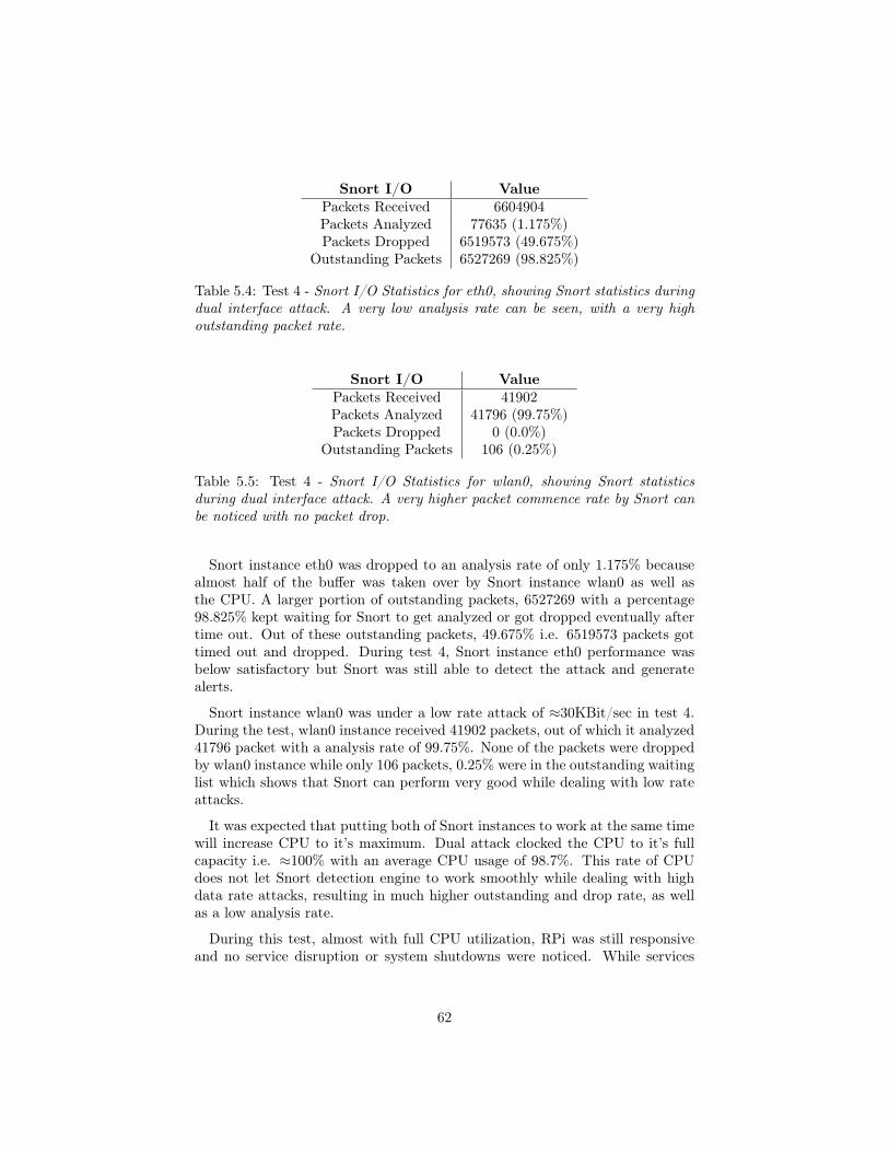
Snort I/O ValuePackets Received 6604904Packets Analyzed 77635 (1.175%)Packets Dropped 6519573 (49.675%)
Outstanding Packets 6527269 (98.825%)
Table 5.4: Test 4 - Snort I/O Statistics for eth0, showing Snort statistics duringdual interface attack. A very low analysis rate can be seen, with a very highoutstanding packet rate.
Snort I/O ValuePackets Received 41902Packets Analyzed 41796 (99.75%)Packets Dropped 0 (0.0%)
Outstanding Packets 106 (0.25%)
Table 5.5: Test 4 - Snort I/O Statistics for wlan0, showing Snort statisticsduring dual interface attack. A very higher packet commence rate by Snort canbe noticed with no packet drop.
Snort instance eth0 was dropped to an analysis rate of only 1.175% becausealmost half of the buffer was taken over by Snort instance wlan0 as well asthe CPU. A larger portion of outstanding packets, 6527269 with a percentage98.825% kept waiting for Snort to get analyzed or got dropped eventually aftertime out. Out of these outstanding packets, 49.675% i.e. 6519573 packets gottimed out and dropped. During test 4, Snort instance eth0 performance wasbelow satisfactory but Snort was still able to detect the attack and generatealerts.
Snort instance wlan0 was under a low rate attack of ≈30KBit/sec in test 4.During the test, wlan0 instance received 41902 packets, out of which it analyzed41796 packet with a analysis rate of 99.75%. None of the packets were droppedby wlan0 instance while only 106 packets, 0.25% were in the outstanding waitinglist which shows that Snort can perform very good while dealing with low rateattacks.
It was expected that putting both of Snort instances to work at the same timewill increase CPU to it’s maximum. Dual attack clocked the CPU to it’s fullcapacity i.e. ≈100% with an average CPU usage of 98.7%. This rate of CPUdoes not let Snort detection engine to work smoothly while dealing with highdata rate attacks, resulting in much higher outstanding and drop rate, as wellas a low analysis rate.
During this test, almost with full CPU utilization, RPi was still responsiveand no service disruption or system shutdowns were noticed. While services
62

related to Ethernet interface eth0 i.e. ssh and Beats were facing multiple ser-vice disconnects, as like in test 2. On interface wlan0, access point was stillfunctioning and it was possible to connect to RPi’s access point. Much like test1 and test 2, no major change in memory consumption was noticed.
A dual attack of RPi is less probable, as it will be rare that both of theinterfaces will be attacked at the same time, but this test does show that main-taining this attack for a long time can probably overwhelm the CPU and canresult in a complete service disrupt. This test concluded that RPi as an IDSgives below average performance in terms of detection of dual interface attacksand CPU consumption. Also, remote monitoring system tends to get disruptedeasily because of the RPi’s 300MBit Ethernet port. Figure 5.4 shows the resultsobtained after test 4, a very high CPU usage can be seen.
Figure 5.4: Test 4 - Memory and CPU consumption during dual attack, a veryhigh CPU rate can be seen because both of the Snort instances are operationalin detecting attacks.
5.5 Monitoring Server
The main purpose of including monitoring service was to visualize the Snortdata and to provide simple readability to Snort alerts e.g. type of active at-tacks, number of alerts generated by Snort, location of attacking IP addressesand details of the Snort rule which detected the attack i.e Signature ID etc.Beats components, Filebeat was responsible for reading Snort alerts at RPi andshipping them to ELK server.
63
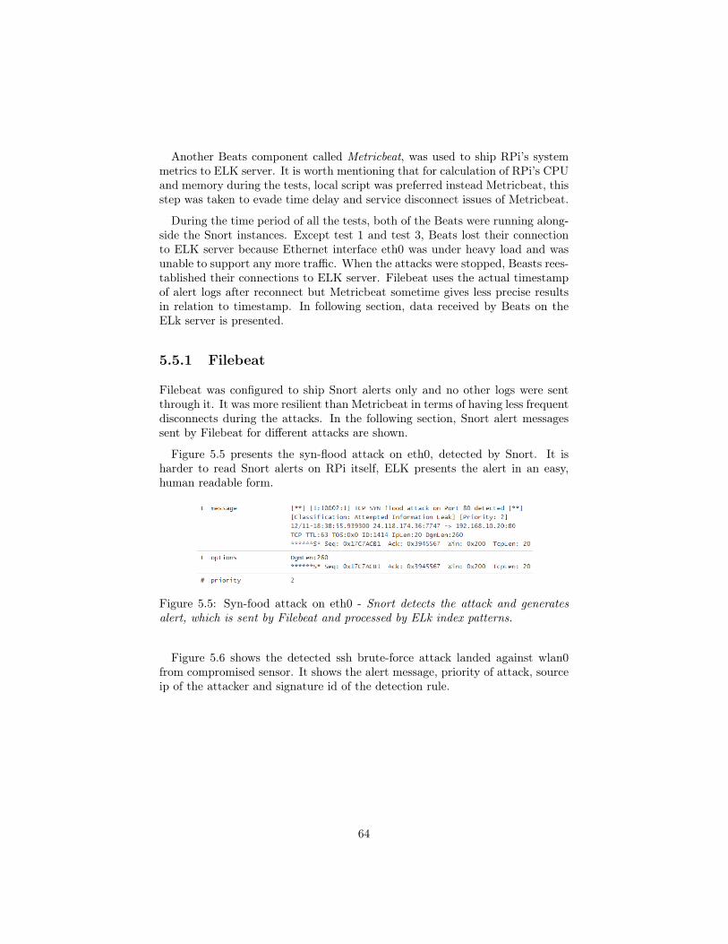
Another Beats component called Metricbeat, was used to ship RPi’s systemmetrics to ELK server. It is worth mentioning that for calculation of RPi’s CPUand memory during the tests, local script was preferred instead Metricbeat, thisstep was taken to evade time delay and service disconnect issues of Metricbeat.
During the time period of all the tests, both of the Beats were running along-side the Snort instances. Except test 1 and test 3, Beats lost their connectionto ELK server because Ethernet interface eth0 was under heavy load and wasunable to support any more traffic. When the attacks were stopped, Beasts rees-tablished their connections to ELK server. Filebeat uses the actual timestampof alert logs after reconnect but Metricbeat sometime gives less precise resultsin relation to timestamp. In following section, data received by Beats on theELk server is presented.
5.5.1 Filebeat
Filebeat was configured to ship Snort alerts only and no other logs were sentthrough it. It was more resilient than Metricbeat in terms of having less frequentdisconnects during the attacks. In the following section, Snort alert messagessent by Filebeat for different attacks are shown.
Figure 5.5 presents the syn-flood attack on eth0, detected by Snort. It isharder to read Snort alerts on RPi itself, ELK presents the alert in an easy,human readable form.
Figure 5.5: Syn-food attack on eth0 - Snort detects the attack and generatesalert, which is sent by Filebeat and processed by ELk index patterns.
Figure 5.6 shows the detected ssh brute-force attack landed against wlan0from compromised sensor. It shows the alert message, priority of attack, sourceip of the attacker and signature id of the detection rule.
64

Figure 5.6: ssh-bruteforce attack on wlan0 - It shows the generated alert bySnort after detection of the attack.
similarly, Figure 5.7 and Figure 5.8 show the detected Snort alerts, presentingalert message of blackNurse attack and XMAS scan respectively.
Figure 5.7: blackNurse attack on eth0 - Snort successfully detects the attack andgenerates alerts. Figure shows the alert message on the ELK server.
Figure 5.8: XMAS scan detected on eth0 - Figure shows the detection of nmapXMAS scan, which normally belongs to first phases of a hacking attempt.
For a system administrator, every information is vital for both pre and postattack countermeasures. Specifically, it is very useful if location of attack IPscould be identified, because the admin can then blacklist those ips either basedon subnet or location. ELK server also provides geoip map of all the uniqueip addresses used for attacks. Figure 5.9 shows the map of countries where theattacks were coming from. The map was generated from test 1 syn flood attackwhere interface eth0 was flooded with spoofed random source addresses, just togenerate different ip data.
It must be taken into consideration that source ip address may not be the
65

actual ip of the attacker in certain type of attacks because hackers generallyspoof their ip addresses (if packet response is not required) or use proxies. TheGeoIP is very useful against scanners, bots traffic, and web crawlers.
Figure 5.9: GeoIP MAP - Showing the country location of attackers based ontheir IP addresses. Red color countries are the top countries where attacks wheregenerated from.
5.5.2 Metricbeat
Metricbeat suffered most of the service disconnects from ELK server as com-pared to Filebeat. It was an additional Beats component added to monitorRPi’s metrics. It can be very useful in cases where any unexpected behaviour ofa system is to be monitored, for example, CPU or memory usage above certainthreshold, level of incoming traffic etc. As discussed before that Metricbeatmight give errors with correct timestamps while shipping data, it was hard togenerate graphs with precise time of attacks, instead, graphs with a longer timeframes are shown in following section. Figures 5.10 and 5.11 show the systemload, memory usage and number of incoming and dropped packets respectivelyduring a time span of 30 days.
In figure 5.10, system load gives information of average system load of RPiin 15 minutes interval in terms of percentage. Similarly, memory represents theaverage memory usage of RPi in term of MBs during same time interval. Itmust be noted that resource consumption statistics generated by local scripton RPi may not correlate or synchronize with Metricbeat results due to servicedisconnect issues of Metricbeat.
66

Figure 5.10: Memory and system load - The line graph generated at ELK serverusing Metricbeat data, showing memory and system load fluctuations during alonger time span.
Figure 5.11: Incoming and Dropped packets - The number of packets receivedand dropped by Ethernet interface. Based on Data shipped by Metricbeat.
Figure 5.11 gives an insight into level of traffic RPi was exposed to duringa total time interval of 30 days. It gives a comparative analysis of number ofincoming packets on interface eth0 and number of packet that were dropped bythe same interface. It can be seen that RPi dropped a large number of packetswhich clearly show a major weakness of RPi’s 300Mbps Ethernet interface.When this interface is exposed to above 300MBit/sec traffic, it starts droppinglarge amount of packets which may or may not effect the RPi CPU depending
67

on the nature of packets. For instance, mere syn packets have a very less effectson CPU in normal situations but ICMP type 3, code 3 packets demand a largeCPU utilization even on comparatively low rate traffic.
68

Chapter 6
Discussion
This chapter provides a critical discussion on project evaluation, the adoptedapproach, implementation, results and analysis and on the project as a whole.Also, suggestions on how this project can be improved is presented in futurework.
6.1 Project Evaluation
IoT market space is expected to be massive in near future. IoT devices are ex-pected to have direct impact on businesses and everyday lives of people. Withthis tremendous growth of IoTs, unfortunately, attacks on these devices hasincreased many fold because of weak to no security of IoT devices. Most ofthe IoT manufacturers focus on higher profit margins, overlooking security as-pects. Most of the commercial security products, specifically, intrusion detectiondevices (IDS) are too costly and demand special hardware, which makes it dif-ficult for average IoT user e.g. smart home or smart building, to afford theseIDS devices.
Keep in view above phenomenon, this thesis was intended to build and testan affordable IDS for common IoT environments. The project used a low price,35$ single board computer device Raspberry Pi and open source IDS Snort.
6.2 The Approach
Snort IDS was placed in a single centralized RPi gateway for simplicity. Fortesting Snort and RPi as an IDS, only those attacks were chosen which are verycommon against IoTs i.e. DoS, dictionary attacks and port scanners. The pro-ject chose an empirical approach and used actual hardware instead simulation,
69
also, real attack tools like hping3, ncrack and nmap were used for testing ofIDS.
Two instances of Snort were deployed on RPi, one for each interface, i.e.Ethernet interface eth0 and wireless interface wlan0. The reason for using dualSnort instance was because Snort is single threaded and can not listen on morethan one instance at a time. Although this approach can be resource overheadif no attacks on wlan0 are expected. Also, certain types of attacks on wlan0can not be detected by Snort, for instance, wireless de-authentication attack onwlan0. Both of the instances were provided with different number and type ofrules based on the nature of their exposure, a total of ≈7000 rules were used.
Two attack points were chosen on RPi, Ethernet interface was attacked usingdifferent data rate attacks, wlan0 was attacked by a compromised connectedsensor with a ssh dictionary attack. To analyze the Snort alerts and visualizeRpi metrics, Beats were used alongside remote monitoring server equipped withELK stack.
6.3 Implementation and challenges
At the time of this thesis writing, only few documented implementation of Snortwith RPi can be seen in reputable journals. It was hard to obtain closely relatedresearch work which used the same setup. in fact, no matching setup was foundtill date which uses a combination of Snort, RPi and ELk stack, this projectwas the first which attempted this combination.
Rpi uses Armv Linux architecture, which has several dependency issues whilecompiling common Linux packages. Compilation of Snort on RPi was notstraight forward and had to be compiled and installed manually form source.It was done after several trial and error and solving dependency issues. Also,choosing ac-bnfa-nq algorithm over Snort default algorithm ac-split was notan instant decision. unfortunately, no reputable document exists that couldprovide a comparative performance analysis of Snort’s current pattern matcheralgorithms. To seek professional advice, Snort developers were consulted on se-clists.org which is an open portal for Snort and other related security software.
Selecting and writing Snort rules was also a difficult process because a singlebad written rule could give inaccurate test result, for instance, in a syn-floodattack rule, if count 1000, seconds 5 is changed to count 10, seconds 5, it willnot only generate a very large amount of alerts but also increase CPU manyfolds. Similarly, if flags:S was put at the end of rule instead in beginning, it candemand more work from pattern matcher algorithms hence increasing resourceusage. Moreover, selection of individual rules which match this project criteriawas a worth a job.
Configuring Beats components for data shipping on RPi was the most time
70

intensive. Currently, Elastic.co which provides official support for Beats andELk stack, do not provide Arm architecture builds of Beats. Also, Beats use Golanguage for compilation, which also demands a manual labour to install andconfigure.
The project first planned to use rsyslog for sending Snort logs to Logstashbut rsyslog did not provide support to ship real time system metrics of RPi.Beats, on the other hand, could not only send Snort alert logs but also couldsend real time system metrics. It was more reasonable to use Beats as it is easierto index data on ELK stack when using Beats (Except Snort index pattern forSnort alerts which had to be written). Installing ELK stack on remote serverwhich is an Ubuntu machine, was comparatively easier and straight forward.This chapter also provided the answer to first question of problem statement i.eHow can we build an affordable and portable IDS solution using RPi and Snort?
6.4 Testing and Analysis
Two testing parameters were set, first, to evaluate Snort performance in termsof detection rate i.e. analysis rate, packets dropped, and number of outstandingpackets, problem with these Snort statistics was that Snort does not providelive on the run statistics, these can only be obtained after Snort exists. Second,to evaluate RPi resource consumption during each test, in terms of total CPUconsumption with memory usage as an additional metric.
Initially, Metricbeat was used to collect these metrics but due to service dis-connect and correct time synchronization issues, a local script was written tocollect these metrics in real time. Instead replaying already captured trafficfrom pcaps using Tcpreplay, actual attacks using Kali Linux were preformed inevery test. The reason of choosing real attacks was to sketch a more realisticattack scenario and accumulate more accurate data.
Test 1 used syn-flood at 100MBit/sec data rate with smaller packets, purposeof the attack was to put Snort on work into detection of this attack as well asconsume most of the bandwidth of Ethernet interface eth0, as a result increasethe CPU usage of RPi. Test increased the CPU to an average of 56% whichhad no mention-able effects on RPi performance but Snort gave a moderateperformance of analyzing only 7.42%. Test 2 and Test 3 gave almost similarSnort statistics except test 3, which clocked the RPi CPU to 96%.
Test 4 was a worst case test scenario where both of the interfaces were attackedsimultaneously. This test clocked the CPU to it’s full potential with an averageof 98.825%. Nonetheless, during these tests, CPU of RPi was tested rigorously,which showed an average performance, due to the fact that even at high CPUrate no system crash, Rpi shutdown or a major system disruption was noted andRpi was still able to perform it’s system operations. Similarly, Snort gave belowaverage performance in detection of high rate attacks, and excellent performance
71

in detection of low rate attacks i.e. detection of wlan0 attack with 99.75%analysis rate. These tests signify that Rpi can perform as an IDS using Snort inaverage traffic flow environments. This also provides the answer to the problemstatement question i.e Does RPi have enough resources to support Snort as anIDS, in terms of resource consumption? and the answer is yes.
These tests uncovered a major weakness of RPi which is the Ethernet inter-face. Rpi’s Ethernet provides a maximum bandwidth support of only 300Mbpswhich is very low for modern internet traffic scenarios. Although it’s Ethernet isdesigned for sensor networks where less data flow is expected but RPi does havethe capability to operate as an IDS in non-sensor based networks, for that, itwill perhaps, need a better Ethernet. Except test 1, every other test completelyengaged Ethernet port and no incoming or outgoing communication was pos-sible. Beats were the biggest victims of Ethernet’s inability of communicationduring these tests. This may gave an idea of using alternative single board com-puters with a better Ethernet port support which may cost relatively higherprice. For instance, Orange Pi Plus 2 and Asus Tinker Board provides oneGigabit Ethernet port with only a marginal price increase. It is recommendedto avoid using the RPi in cases where a high data rate traffic is expected. If, incase it is unavoidable then RPi alternatives with better specifications could beused.
In [46], authors presented a similar approach using RPi model 2 B. Theycame to almost similar conclusion that Ethernet interface of RPi can be a ma-jor weakness, but authors did not provide a worst case scenario neither theycould provide a clear view of their system design. In [39] authors used beha-viour profiling, which is extremely difficult to implement in common IoT setup,similarly in [40], authors used artificial immune cells which can be computationaland resource overhead while [41] is limited to detect only few special attacks.In [42], authors used only a single metric for detecting attacks i.e. energy con-sumption. Also [43] was designed for only 6LoWPAN while [44] proposed ahybrid approach which is too complex to implement in common IoT environ-ments. Finally, except [46] none of the authors could provide cost affordabilityof their proposals.
This project not only identified best to worst case scenarios but also provideda clear system design with cost affordability. Moreover, this project has providedprobably the first practical implementation of one of the most advanced yet freemonitoring service ELk stack, on Rpi with open-source IDS Snort.
Short coming of this project probably is the inability of detecting direct wire-less attacks on wlan0 access point. A de-authentication attack on RPi accesspoint will disconnect any connected IoT devices and the attack will go unnoticedof Snort instance. Since this attack is very rare and need a very close range toinitiate the attack, it can be considered less probable.
72

6.5 Future Work
The project can be improved by changing several parameters. For instance,instead using two instances of Snort, wlan0 instance of Snort can be changedwith Kismet IDS instead which is a specialized wireless IDS. This setup willthen provide intrusion detection on Ethernet interface with Snort while Kismetwill take care of wlan0 interface.
For a pure Wireless IDS in a wider IoT environment, multiple battery poweredRPi’s with Kismet can be deployed with a distributed approach i.e. in a cluster,where each device cooperates with it’s neighbour devices, by exchanging inform-ation of attack detection, battery levels, and load balancing etc. These cluster ofIDS devices can be programmed to autonomously choose their cluster heads forinstance those devices with higher battery can be chosen as cluster head or someother parameter can be set for this. For monitoring of battery consumption andpower levels, Beats can be deployed with a longer data shipping interval to savepower.
It is also possible to make these clustered IDS sensors autonomous in decisionmaking and load distribution by introducing very basic machine learning usingpython. Moreover, this is also possible to turn Snort IDS into an IPS (intrusionprevention system) but it may not work good in wireless environments. Otheropen-source IDSs like Bro and Suricata can also be used as an alternative toSnort.
73

Chapter 7
Conclusion
This thesis proposed an IDS system for IoTs using very common, low priceand low spec hardware with freely available open source intrusion detectionsystem. The purpose of the thesis was to open new paths into IoT security bypractically demonstrating that security of IoTs in terms of Intrusion detectioncan be achieved by using simple and affordable tools. It provided an affordablealternative to costly commercial IDS systems which are not feasible for commonIoT environments like smart home and smart buildings.
The proposed IDS can be deployed in most of the IoT environments wheredata traffic is expected to be low to medium, for instance, in smart buildings,public transport stations or in personal home security. To prove the claims of theproject, it was evaluated and tested under various data traffic rates and by usingdifferent types of real attacks. Best to worst case scenarios were implementedto test RPi’s capability of hosting Snort, tests result confirmed the feasibility ofRaspberry Pi as an IDS and proved that under most common IoT environments,Raspberry Pi can host Snort and can deliver the expected intrusion detectionfunctionality.
Although certain tests increased the RPi CPU to almost 100% but it was notentirely due to Snort processes but was associated with data rates. RaspberryPi hosted Snort smoothly with no significant impact on memory neither CPUshutdowns were noted during any of the tests, although It would be a goodidea to further test the proposed system. This project has successfully builtan affordable intrusion detection system for IoTs and has managed to test andprove it’s claims. Also, this was the first project which used a combination ofSnort, Raspberry Pi and ELK Stack.
74

Bibliography
[1] K. Ashton. That ‘internet of things’ thing. RFiD Journal, 22:97–114, 2009.
[2] https://www.forbes.com/sites/louiscolumbus/2017/12/10/2017-roundup-of-internet-of-things-forecasts/#3fc008701480 [Accessed September 32018]
[3] Introduction: Advances in IoT research and applications, Pan Wang &Ricardo Valerdi & Shangming Zhou & Ling Li, Published online: 11 March2015 Springer Science+Business Media New York 2015.
[4] https://www.cisco.com/c/dam/en_us/about/ac79/docs/retail/Beyond-the-New-Normal_IBSG_051211-FINAL.pdf [Accessed September 32018]
[5] http://sro.sussex.ac.uk/54129/1/07110295.pdf [Accessed September 52018]
[6] G. Montenegro, N. Kushalnagar, J. Hui, and D. Culler, “Transmission ofIPv6 packets over IEEE 802.15.4 networks,” in Internet Engineering TaskForce, RFC 4944, 2007.
[7] T. W. (Ed.), P. T. (Ed.), A. Brandt, J. Hui, R. Kelsey, P. Levis, K. Pister,R.Struik, J. Vasseur, and R. Alexander, “RPL: IPv6 routing protocol for low-power and lossy networks,” in IETF, RFC 6550, 2012.
[8] Z. Shelby, K. Hartke, and C. Bormann, “Constrained ap-plication protocol (CoAP),” Internect Draft, Available at:http://datatracker.ietf.org/wg/core/charter.
[9] Z. Sheng, S. Yang, Y. Yu, A. V. Vasilakos, J. A. McCann, and K. K.Leung,“A survey on the IETF protocol suite for the internet of things: standards,challenges, and opportunities,” IEEE Wireless Communications Magazine,vol. 20, no. 6, pp. 91–98, 2013.
[10] European Telecommunication Standards Institute,(ETSI),http://www.etsi.org/technologies-clusters/technologies/m2m[Accessed September 5 2018]
75

[11] D. Katusic, M. Weber, I. Bojic, G. Jezic, and M. Kusek, “Market, stand-ardization, and regulation development in machine-to-machine communic-ations,”in 20th International Conference on Software, Telecommunicationsand Computer Networks (SoftCOM), Sept 2012, pp. 1–7.
[12] Internet of Things: Innovation with Chinese Characteristics,http://www.hoganlovells.com/internet-of-things-innovation-withchinese-characteristics-09-12-2013/ [Accessed September 6 2018]
[13] https://iot-analytics.com/top-10-iot-segments-2018-real-iot-projects/ [Ac-cessed September 6 2018]
[14] http://sro.sussex.ac.uk/54129/1/07110295.pdf [Accessed September 62018]
[15] https://altizon.com/varroc-automotive-case-study/ [Accessed September10 2018]
[16] OASIS, MQTT Version 3.1.1, Std., 2014.
[17] Dae-Hyeok Mun, Minh Le Dinh, and Young-Woo Kwon, Department ofComputer Science, "An Assessment of Internet of Things Protocols forResource-Constrained Applications," IEEE 40th Annual Computer Soft-ware and Applications Conference 2016.
[18] Z. Shelby, K. Hartke, and C. Bormann, “The constrained application pro-tocol (CoAP),” 2014.
[19] I. Fette and A. Melnikov, “The Websocket Protocol,” 2011.
[20] https://xmpp.org/about/ [Accessed September 12 2018]
[21] Q. Jing, A. V. Vasilakos, J. Wan, J. Lu, and D. Qiu, “Security of theInternet of Things: Perspectives and challenges,” Wireless Netw., vol. 20,no. 8, pp. 2481–2501, Nov. 2014.
[22] M. Frustaci, P. Pace, G. Aloi and G. Fortino, "Evaluating Critical SecurityIssues of the IoT World: Present and Future Challenges," in IEEE Internetof Things Journal, vol. 5, no. 4, pp. 2483-2495, Aug. 2018.
[23] https://www.owasp.org/index.php/OWASP_Internet_of_Things_Project#tab=IoT_Attack_Surface_Areas. [Accessed September 122018]
[24] C. Karlof, D. Wagner, “Secure Routing in Wireless Sensor Networks: At-tacks and Countermeasures”, 2003
[25] https://www.sans.org/reading-room/whitepapers/detection/understanding-intrusion-detection-systems-337 [Accessed September 12 2018]
[26] Steven R Snapp et al.“DIDS (distributed intrusion detection system) mo-tivation, architecture, and an early prototype.” In: Proceedings of the 14th
76

national computer security conference. Vol. 1. Washington, DC. 1991, pp.167–176.
[27] https://snort.org/ [Accessed September 15 2018]
[28] https://www.bro.org/sphinx/intro/index.html [Accessed September 262018]
[29] https://redmine.openinfosecfoundation.org/projects/suricata/wiki/What_is_Suricata [Accessed September 26 2018]
[30] F. Hock and P. Kortiš, "Commercial and open-source based Intrusion De-tection System and Intrusion Prevention System (IDS/IPS) design for anIP networks," 2015 13th International Conference on Emerging eLearningTechnologies and Applications (ICETA), Stary Smokovec, 2015, pp. 1-4.
[31] A. Mishra, K. Nadkarni, and A. Patcha, “Intrusion detection in wireless adhoc networks”, IEEE Wireless Communications, 11 (1), 48-60, 2004.
[32] T. Anantvalee, and W. Jie, “A survey on intrusion detection systems inmobile ad hoc networks”, Wireless Network Security, 2, 159-180, 2017.
[33] S. Kumar, and K. Dutta, “Intrusion detection in mobile ad hoc networks:techniques, systems, and future challenges”, Security and CommunicationNetworks, 9 (14), 2484-2556, 2016
[34] A. Farooqi, and F. Khan, “Intrusion detection systems for wireless sensornetworks: a survey”, In Communication and Networking Communicationsin Computer and Information Science, 56, Springer, Berlin, Heidelberg,234-241, 2009
[35] A. Abduvaliyev, A. Pathan, Z. Jianying, R. Roman, and W.WaiChoong2013, “On the vital areas of intrusion detection systems in wire-less sensor networks”, IEEE Communications Surveys & Tutorials, 15 (3),1223-1237, 2013.
[36] I. Butun, S. Morgera, and R. Sankar, “A survey of intrusion detection sys-tems in wireless sensor networks”, Communications Surveys and TutorialsIEEE, 16 (1), 266-282, 2014.
[37] R. Mitchell, and I. Chen, “A survey of intrusion detection techniques forcyber-physical systems”, ACM Computing Surveys (CSUR), 46 (4), 55,2014.
[38] B. B. Zarpelão, R. S. Miani, C. T. Kawakani, and S. C. de Alvarenga, “Asurvey of intrusion detection in internet of things,” Journal of Network andComputer Applications, vol. 84, pp. 25-37, 2017.
[39] E. Cho, J. Kim, and C. Hong, “Attack model and detection scheme forbotnet on 6LoWPAN,” In Management Enabling the Future Internet forChanging Business and New Computing Services, Lecture Notes in Com-puter Science 5787. Springer, Berlin, Heidelberg, 515-518, 2009.
77

[40] C. Liu, J. Yang, Y. Zhang, R. Chen, and J. Zeng, “Research on immunity-based intrusion detection technology for the Internet of Things,” In: Nat-ural Computation (ICNC), 2011 Proceedings of the Seventh InternationalConference, Vol. 1, pp. 212-216, 2011.
[41] S. Raza, L. Wallgren, and T. Voigt, “SVELTE: real-time intrusion detectionin the Internet of Things,” Ad Hoc Network, 11 (8), 2661-2674, 2013.
[42] T. Lee, C. Wen, L. Chang, H. Chiang, and M. Hsieh, “A lightweight intru-sion detection scheme based on energy consumption analysis in 6LowPAN,”In: Advanced Technologies, Embedded and Multimedia for Human-centricComputing, Lecture Notes in Electrical Engineering, 260. Springer, Neth-erlands, 1205-1213, 2014.
[43] C. Cervantes, D. Poplade, M. Nogueira, and A. Santos, “Detection of sink-hole attacks for supporting secure routing on 6LoWPAN for Internet ofThings,” In: 2015 IFIP/IEEE International Symposium on Integrated Net-work Management (IM), pp. 606-611, 2015
[44] A. Le, J. Loo, K. Chai, and M. Aiash, “A specification-based IDS for de-tecting attacks on RPL-based network topology,” Information, 7 (2), 25,2016.
[45] D. Midi, A. Rullo, A. Mudgerikar, and E. Bertino, “Kalis: A system forknowledge-driven adaptable intrusion detection for the Internet of Things,”In Proceedings of the IEEE 37th International Conference on DistributedComputing Systems (ICDCS’17), 2017
[46] A. Sforzin, F. G. Mármol, M. Conti and J. Bohli, "RPiDS: Raspberry PiIDS — A Fruitful Intrusion Detection System for IoT," 2016 Intl IEEE,Toulouse, 2016, pp. 440-448.
[47] https://www.zigbee.org/ [Accessed October 5 2018]
[48] https://wave2m.com.cutestat.com/ [Accessed October 5 2018]
[49] https://www.isa.org/standards-publications/isa-publications/intech-magazine/2012/december/web-exclusive-analysis-wireless-industrial-automation-standards-isa-100-11a-wirelesshart/ [Accessed October 52018]
[50] https://www.profibus.com/ [Accessed October 5 2018]
[51] https://www.omg.org/ [Accessed October 5 2018]
[52] http://malware.wikia.com/wiki/Sub7 [Accessed October 10 2018]
[53] https://hackstory.net/BackOrifice [Accessed October 10 2018]
[54] https://nmap.org/ [Accessed October 10 2018]
[55] https://sectools.org/tool/l0phtcrack/ [Accessed October 10 2018]
[56] https://github.com/Snorby/snorby [Accessed October 10 2018]
78

[57] http://acidlab.sourceforge.net/ [Accessed October 10 2018]
[58] https://www.elastic.co/elk-stack [Accessed October 10 2018]
[59] https://sourceforge.net/projects/secureideas/ [Accessed October 10 2018]
[60] http://www.tcpdump.org/manpages/tcpdump.1.html [Accessed October10 2018]
[61] https://www.mcafee.com/enterprise/en-us/products/network-security-platform.html [Accessed October 18 2018]
[62] https://www.trendmicro.com/en_us/business/products/network/intrusion-prevention/tipping-point-threat-protection-system.html [Accessed October18 2018]
[63] https://www.hillstonenet.com/products/network-intrusion-prevention-system-s-series/ [Accessed October 18 2018]
[64] https://www.gartner.com/reviews/market/intrusion-prevention-systems/vendor/huawei/product/network-intelligent-protection-nip-system. [Accessed October 18 2018]
[65] https://www.raspberrypi.org/ [Accessed October 22 2018]
[66] Alfred V. Aho and Margaret J. Corasik. Efficient String Matching: An Aidto Bibliographic. Search: Bell Labs, Communications of the ACM Jun 1975Volume 18 Number 6.
[67] https://snort-org-site.s3.amazonaws.com/production/document_files/files/000/000/085/original/OptimizingPathernMatchingForIDS.pdf [Ac-cessed October 25 2018]
[68] https://growthenabler.com/flipbook/pdf/IOT%20Report.pdf [AccessedSeptember 25 2018]
[69] https://rules.emergingthreats.net/open/snort-2.9.0/rules/ [Accessed Octo-ber 27 2018]
[70] https://www.snort.org/talos [Accessed October 27 2018]
[71] https://www.snort.org/downloads#rules [Accessed October 27 2018]
[72] https://www.kismetwireless.net/ [Accessed October 29 2018]
[73] https://golang.org/dl/ [Accessed October 29 2018]
[74] https://www.kali.org [Accessed October 29 2018]
[75] https://www.elastic.co/elk-stack [Accessed November 6 2018]
[76] http://www.orangepi.org/orangepiplus2/ [Accessed November 6 2018]
[77] https://www.asus.com/us/Single-Board-Computer/Tinker-Board/ [Ac-cessed October 4 2018]
79

[78] http://www.banana-pi.org/m3.html [Accessed October 4 2018]
[79] http://en.t-firefly.com/product/rk3288 [Accessed October 4 2018]
[80] https://www.fs-net.de/en/products/armstone/armstonea9/ [Accessed Oc-tober 4 2018]
[81] https://www.kismetwireless.net/ [Accessed November 8 2018]
80

Appendices
81
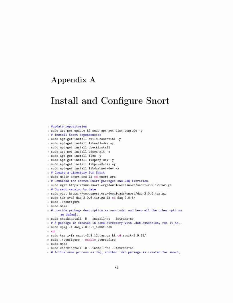
Appendix A
Install and Configure Snort
1 #update repositories2 sudo apt-get update && sudo apt-get dist-upgrade -y3 # install Snort dependencies4 sudo apt-get install build-essential -y5 sudo apt-get install libnet1-dev -y6 sudo apt-get install checkinstall7 sudo apt-get install bison git -y8 sudo apt-get install flex -y9 sudo apt-get install libpcap-dev -y
10 sudo apt-get install libpcre3-dev -y11 sudo apt-get install libdumbnet-dev -y12 # Create a directory for Snort13 sudo mkdir snort_src && cd snort_src14 # Download the source Snort packages and DAQ libraries.15 sudo wget https://www.snort.org/downloads/snort/snort-2.9.12.tar.gz16 # Current version by date17 sudo wget https://www.snort.org/downloads/snort/daq-2.0.6.tar.gz18 sudo tar xvzf daq-2.0.6.tar.gz && cd daq-2.0.6/19 sudo ./configure20 sudo make21 # provide package description as snort-daq and keep all the other options
as default.22 sudo checkinstall -D --install=no --fstrans=no23 # A package is created in same directory with .dab extension, run it as..24 sudo dpkg -i daq_2.0.6-1_armhf.deb25 cd ..26 sudo tar xvfz snort-2.9.12.tar.gz && cd snort-2.9.12/27 sudo ./configure --enable-sourcefire28 sudo make29 sudo checkinstall -D --install=no --fstrans=no30 # follow same process as daq, another .deb package is created for snort,
82
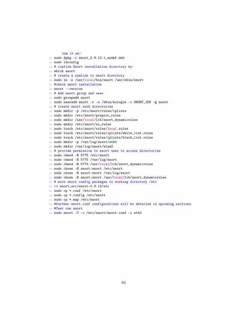
run it as:31 sudo dpkg -i snort_2.9.12-1_armhf.deb32 sudo ldconfig33 # confirm Snort installation directory by:34 which snort35 # create a symlink to snort directory36 sudo ln -s /usr/local/bin/snort /usr/sbin/snort37 #check snort installation38 snort --version39 # Add snort group and user40 sudo groupadd snort41 sudo useradd snort -r -s /sbin/nologin -c SNORT_IDS -g snort42 # create snort work directories43 sudo mkdir -p /etc/snort/rules/iplists44 sudo mkdir /etc/snort/preproc_rules45 sudo mkdir /usr/local/lib/snort_dynamicrules46 sudo mkdir /etc/snort/so_rules47 sudo touch /etc/snort/rules/local.rules48 sudo touch /etc/snort/rules/iplists/white_list.rules49 sudo touch /etc/snort/rules/iplists/black_list.rules50 sudo mkdir -p /var/log/snort/eth051 sudo mkdir /var/log/snort/wlan052 # provide permission to snort user to access directories53 sudo chmod -R 5775 /etc/snort54 sudo chmod -R 5775 /var/log/snort55 sudo chmod -R 5775 /usr/local/lib/snort_dynamicrules56 sudo chown -R snort:snort /etc/snort57 sudo chown -R snort:snort /var/log/snort58 sudo chown -R snort:snort /usr/local/lib/snort_dynamicrules59 # move snort config packages to working directory /etc60 cd snort_src/snort-2.9.12/etc61 sudo cp *.conf /etc/snort62 sudo cp *.config /etc/snort63 sudo cp *.map /etc/snort64 #further snort.conf configurations will be detailed in upcoming sections65 #Test run snort66 sudo snort -T -c /etc/snort/snort.conf -i eth0
83

Appendix B
Hostapd and ISC serverconfigurations
1 sudo apt-get update2 # install required packages3 sudo apt-get install hostapd isc-dhcp-server4 sudo apt-get install iptables-persistent5 # Edit dhcpd.conf6 sudo nano /etc/dhcp/dhcpd.conf7 # comment of these lines with "#"8 #option domain-name "example.org";9 #option domain-name-servers ns1.example.org, ns2.example.org;
10 # uncomment #authoritative;11 authoritative;12 # Add following at the end of file, change ip's accordingly13 subnet 192.168.42.0 netmask 255.255.255.0 {14 range 192.168.42.1 192.168.42.40;15 option broadcast-address 192.168.42.255;16 option routers 192.168.42.1,192.168.10.1;17 default-lease-time 600;18 max-lease-time 7200;19 option domain-name "local";20 option domain-name-servers 8.8.8.8,
8.8.4.4,192.168.42.1,192.168.10.1;21 }22 # Edit isc-dhcp-server file and add23 sudo nano /etc/default/isc-dhcp-server24 INTERFACESv4="wlan0"25 # make sure wlan0 is down26 sudo ifdown wlan027 # Edit file /etc/network/interfaces.d/wlan028 sudo nano /etc/network/interfaces.d/wlan0
84

29 # Add following and save file30 allow-hotplug wlan031 iface wlan0 inet static32 address 192.168.42.133 netmask 255.255.255.034 # Time to enable configure hostapd, hostapd.conf does not exist by
default35 sudo nano /etc/hostapd/hostapd.conf36 # Add following code37 interface=wlan038 ssid=Pi_AP # any AP name39 country_code=NO40 hw_mode=g41 channel=642 macaddr_acl=043 auth_algs=144 ignore_broadcast_ssid=045 wpa=246 wpa_passphrase=yourpassword47 wpa_key_mgmt=WPA-PSK48 wpa_pairwise=CCMP49 wpa_group_rekey=8640050 ieee80211n=151 wme_enabled=152 # Edit /etc/default/hostapd53 sudo nano /etc/default/hostapd54 # and add following55 DAEMON_CONF="/etc/hostapd/hostapd.conf"56 # Enable ipv4 forwarding57 sudo nano /etc/sysctl.conf58 # and add at the end of file59 net.ipv4.ip_forward=160 # Run command61 sudo sh -c "echo 1 > /proc/sys/net/ipv4/ip_forward"62 # Add iptables rules63 sudo iptables -t nat -A POSTROUTING -o eth0 -j MASQUERADE64 sudo iptables -A FORWARD -i eth0 -o wlan0 -m state --state RELATED,
ESTABLISHED -j ACCEPT65 sudo iptables -A FORWARD -i wlan0 -o eth0 -j ACCEPT66 # verify iptable rules by67 sudo iptables -t nat -S68 sudo iptables -S69 # save iptable rules persistently70 sudo sh -c "iptables-save > /etc/iptables/rules.v4"71 # turn on wlan0 and restart72 sudo ifup wlan073 sudo reboot74 # start services75 sudo service hostapd start76 sudo service isc-dhcp-server start
85

77 # verify status78 sudo service hostapd status79 sudo service isc-dhcp-server status80 # Follow commands can also be used to start daemon services81 sudo update-rc.d hostapd enable82 sudo update-rc.d isc-dhcp-server enable
86
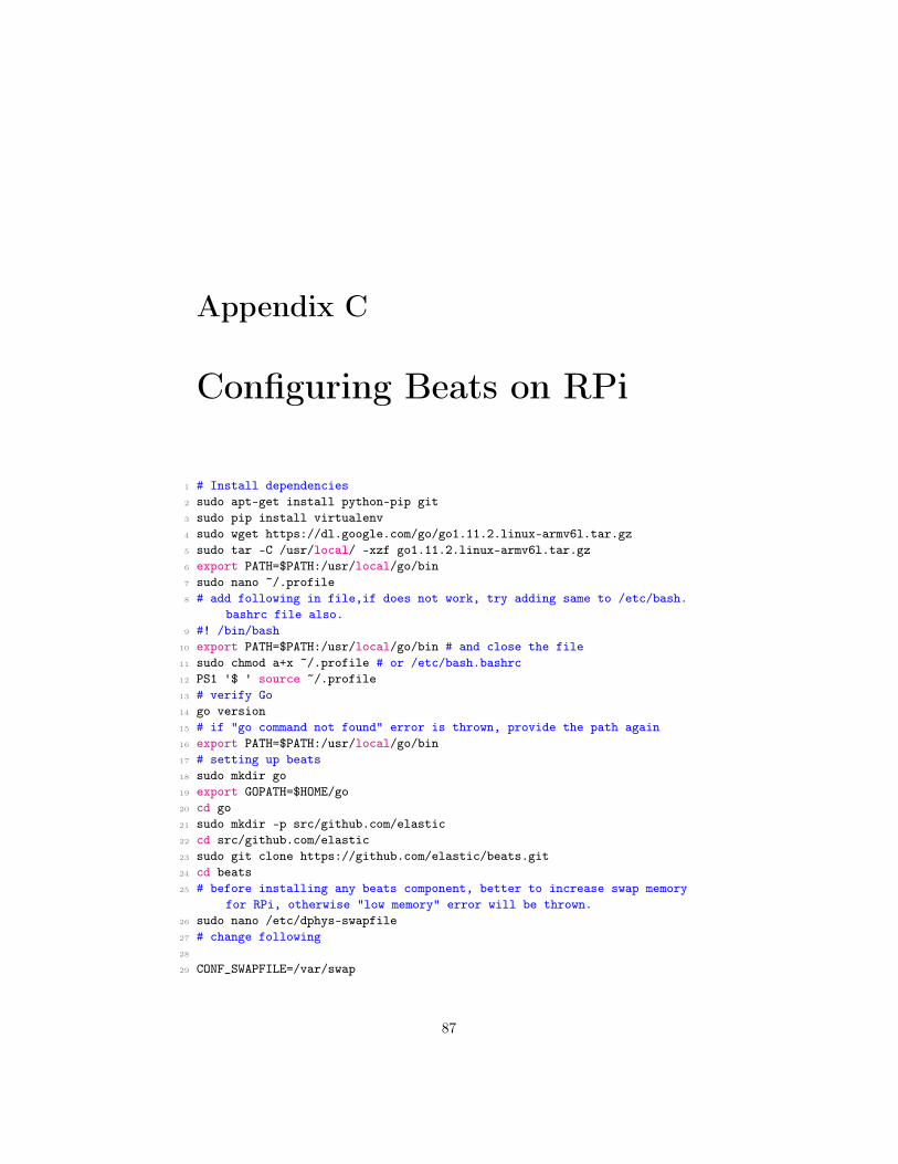
Appendix C
Configuring Beats on RPi
1 # Install dependencies2 sudo apt-get install python-pip git3 sudo pip install virtualenv4 sudo wget https://dl.google.com/go/go1.11.2.linux-armv6l.tar.gz5 sudo tar -C /usr/local/ -xzf go1.11.2.linux-armv6l.tar.gz6 export PATH=$PATH:/usr/local/go/bin7 sudo nano ~/.profile8 # add following in file,if does not work, try adding same to /etc/bash.
bashrc file also.9 #! /bin/bash
10 export PATH=$PATH:/usr/local/go/bin # and close the file11 sudo chmod a+x ~/.profile # or /etc/bash.bashrc12 PS1 '$ ' source ~/.profile13 # verify Go14 go version15 # if "go command not found" error is thrown, provide the path again16 export PATH=$PATH:/usr/local/go/bin17 # setting up beats18 sudo mkdir go19 export GOPATH=$HOME/go20 cd go21 sudo mkdir -p src/github.com/elastic22 cd src/github.com/elastic23 sudo git clone https://github.com/elastic/beats.git24 cd beats25 # before installing any beats component, better to increase swap memory
for RPi, otherwise "low memory" error will be thrown.26 sudo nano /etc/dphys-swapfile27 # change following28
29 CONF_SWAPFILE=/var/swap
87
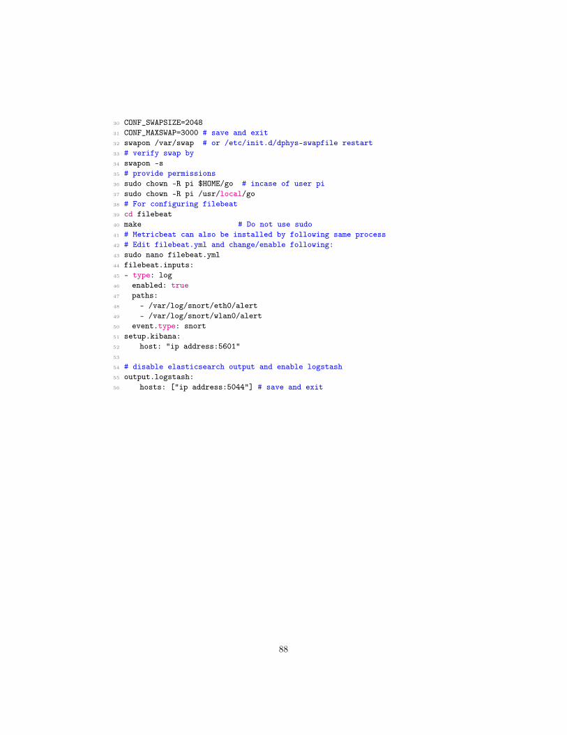
30 CONF_SWAPSIZE=204831 CONF_MAXSWAP=3000 # save and exit32 swapon /var/swap # or /etc/init.d/dphys-swapfile restart33 # verify swap by34 swapon -s35 # provide permissions36 sudo chown -R pi $HOME/go # incase of user pi37 sudo chown -R pi /usr/local/go38 # For configuring filebeat39 cd filebeat40 make # Do not use sudo41 # Metricbeat can also be installed by following same process42 # Edit filebeat.yml and change/enable following:43 sudo nano filebeat.yml44 filebeat.inputs:45 - type: log46 enabled: true47 paths:48 - /var/log/snort/eth0/alert49 - /var/log/snort/wlan0/alert50 event.type: snort51 setup.kibana:52 host: "ip address:5601"53
54 # disable elasticsearch output and enable logstash55 output.logstash:56 hosts: ["ip address:5044"] # save and exit
88

Appendix D
Setup ELK on Openstack
1 #The Server should have at leas 2 CPU cores and 2GB RAM2 # Installing Java3 sudo apt install software-properties-common apt-transport-https -y4 sudo add-apt-repository ppa:webupd8team/java -y5 sudo apt install oracle-java8-installer -y6 # verify Java installation7 java -version8 # Setup Java environment9 update-alternatives --config java
10 # Create the profile file under profile.d directory11 sudo nano /etc/profile.d/java.sh12 # Add following13 #Set JAVA_HOME14 JAVA_HOME="/usr/lib/jvm/java-8-oracle"15 export JAVA_HOME16 PATH=$PATH:$JAVA_HOME17 export PATH18 # Provide permissions and source the file19 chmod +x /etc/profile.d/java.sh20 source /etc/profile.d/java.sh21 # Verify Java environment22 echo $JAVA_HOME23 # Installing Elasticsearch24 wget -qO - https://artifacts.elastic.co/GPG-KEY-elasticsearch | sudo apt-
key add -25 echo "deb https://artifacts.elastic.co/packages/6.x/apt stable main" |
sudo tee -a /etc/apt/sources.list.d/elastic-6.x.list26 sudo apt update27 sudo apt install elasticsearch -y28 # Configure elasticsearch.yml file29 cd /etc/elasticsearch/
89
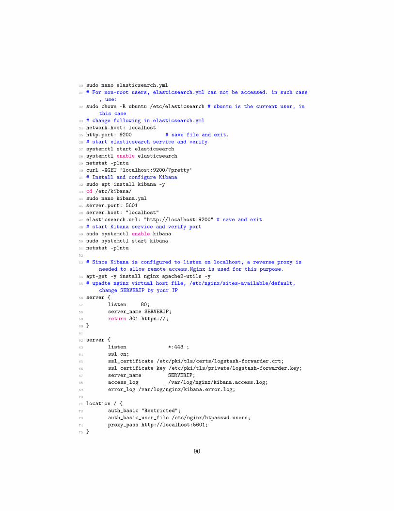
30 sudo nano elasticsearch.yml31 # For non-root users, elasticsearch.yml can not be accessed. in such case
, use:32 sudo chown -R ubuntu /etc/elasticsearch # ubuntu is the current user, in
this case33 # change following in elasticsearch.yml34 network.host: localhost35 http.port: 9200 # save file and exit.36 # start elasticsearch service and verify37 systemctl start elasticsearch38 systemctl enable elasticsearch39 netstat -plntu40 curl -XGET 'localhost:9200/?pretty'41 # Install and configure Kibana42 sudo apt install kibana -y43 cd /etc/kibana/44 sudo nano kibana.yml45 server.port: 560146 server.host: "localhost"47 elasticsearch.url: "http://localhost:9200" # save and exit48 # start Kibana service and verify port49 sudo systemctl enable kibana50 sudo systemctl start kibana51 netstat -plntu52
53 # Since Kibana is configured to listen on localhost, a reverse proxy isneeded to allow remote access.Nginx is used for this purpose.
54 apt-get -y install nginx apache2-utils -y55 # upadte nginx virtual host file, /etc/nginx/sites-available/default,
change SERVERIP by your IP56 server {57 listen 80;58 server_name SERVERIP;59 return 301 https://;60 }61
62 server {63 listen *:443 ;64 ssl on;65 ssl_certificate /etc/pki/tls/certs/logstash-forwarder.crt;66 ssl_certificate_key /etc/pki/tls/private/logstash-forwarder.key;67 server_name SERVERIP;68 access_log /var/log/nginx/kibana.access.log;69 error_log /var/log/nginx/kibana.error.log;70
71 location / {72 auth_basic "Restricted";73 auth_basic_user_file /etc/nginx/htpasswd.users;74 proxy_pass http://localhost:5601;75 }
90

76 }77 # save and exit the file78 # Generating password for kibana79 sudo htpasswd -c /etc/nginx/.kibana-user KibanaUser # provide the
password and also change KibanaUser80 ln -s /etc/nginx/sites-available/kibana /etc/nginx/sites-enabled/ nginx -
t81 # Enable nginx82 systemctl enable nginx83 systemctl restart nginx84 #Install and configure Logstash85 apt-get update86 apt-get -y install logstash87
88 #Generate SSL Certificates, since Filebeat is used to ship logs from RPito ELK Server, it is need to create an SSL certificate and key pair.The certificate is used by Filebeat to verify the identity of ELKServer. It is optional.
89 mkdir -p /etc/pki/tls/certs90 mkdir /etc/pki/tls/private91
92 sed -i "230i subjectAltName = IP: ${server_address}" /etc/ssl/openssl.cnf93 cd /etc/pki/tls94 openssl req -config /etc/ssl/openssl.cnf -x509 -days 3650 -batch -nodes -
newkey rsa:2048 -keyout private/logstash-forwarder.key -out certs/logstash-forwarder.crt
95 cd96
97 # Configure Logstash files, i.e. input, output and filter.98 # configuring /etc/logstash/conf.d/02-beats-input.conf99 sudo nano /etc/logstash/conf.d/02-beats-input.conf
100 input {101 beats {102 port => 5044103 # ssl => true104 # ssl_certificate => "/etc/pki/tls/certs/logstash-forwarder.crt"105 # ssl_key => "/etc/pki/tls/private/logstash-forwarder.key"106 type => "Snort"107 }108 }109 # save and exit110 # configure Snort filter file111 sudo nano 11-snort-filter.conf112 filter {113 if [type] == "Snort" {114 grok { match => { "message" => "\[\*\*\] \[%{GREEDYDATA:Signature}\]
%{GREEDYDATA:SnortMessage} \[\*\*\]%{GREEDYDATA:Classification}\[Priority: %{NUMBER:priority:int}\] \n%{GREEDYDATA:snortDate} %{IP:SourceIP}:%{NUMBER:SourcePort:int} \-\> %{IP:DestinationIP}:%{NUMBER:DestinationPort:int}\n%{WORD:Protocol} TTL:%{NUMBER:TTL:
91

int} TOS:%{BASE16NUM:TOS} ID:%{NUMBER:ID:int} IpLen:%{NUMBER:IpLen:int} %{GREEDYDATA:options}"}
115 # remove_field => [ "message" ]116 }117
118 date {119 match => ["snortDate", "MM/dd-HH:mm:ss.SSSSSS"]120 target => "@timestamp"121 remove_field => ["snortDate"]122 timezone => "Europe/Amsterdam"123 locale => "en_US"124 }125 geoip{126 source=>"SourceIP"127 }128 }129 }130 # Configure elasticsearch output file131 sudo nano 30-elasticsearch-output.conf132 output {133 if [type] == "Snort" {134 elasticsearch {135 hosts => ["localhost:9200"]136 manage_template => false137 index => "snort-%{+YYYY.MM.dd}"138 }139 }140 }141 # save and exit142
143 # Verify and reboot setup144 java -version145 service nginx restart146 service elasticsearch restart147 service kibana restart148 service logstash restart149 systemctl enable elasticsearch150 systemctl enable logstash151 systemctl enable kibana
92

Appendix E
Snort Instances and Gnuplot
1
2 # snort.sh file, Run by bash snort.sh3 # No need to run stats.sh file separately for plotting4
5 #! bin/bash6 #Script to initiate Snort instances from given options.7 #It will open new terminal (tested only in RPi Raspbian stretch) and run
the given instances.8 # Author: HH@Khan9
10 RED='\033[0;31m'11 YEL='\033[0;93m'12 GRE='\033[0;32m'13 NOCO='\033[0m'14
15 while true; do16 echo -ne "${GRE}Choose option to run snort and beats--------: \n\
t${YEL}[1]: ${NOCO}Run Snort on Eth0\n\t${YEL}[2]: ${NOCO}RunSnort on wlan0\n\t${YEL}[3]: ${NOCO}Run Snort on both eth0
and wlan0 \n\t${YEL}[4]: ${NOCO}Run Filebeat and Metricbeat\n\t${YEL}[5]: ${NOCO}Run Snort on eth0 with beats\n\t${YEL}[6]: ${NOCO}Run both snort instances and beats\n\t"
17
18 read OPTION19 case $OPTION in20 1 )21 echo -ne "\n\t\t${GRE}Running snort on eth0
------------------------------------"22 lxterminal --command="/bin/bash -c 'bash stats.sh; /bin/bash'" #
Calling Plotting file before instance run.23 sleep 5 # plotting file starts 5 seconds
93
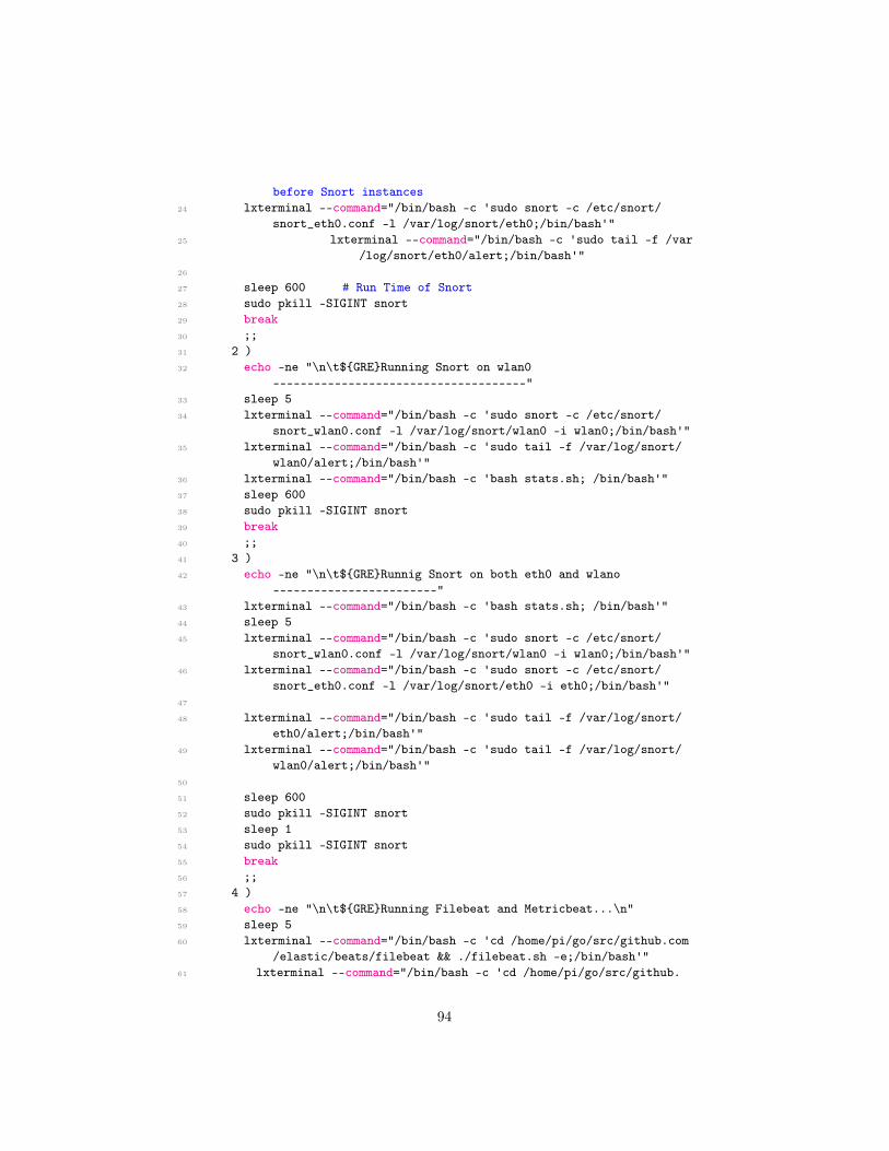
before Snort instances24 lxterminal --command="/bin/bash -c 'sudo snort -c /etc/snort/
snort_eth0.conf -l /var/log/snort/eth0;/bin/bash'"25 lxterminal --command="/bin/bash -c 'sudo tail -f /var
/log/snort/eth0/alert;/bin/bash'"26
27 sleep 600 # Run Time of Snort28 sudo pkill -SIGINT snort29 break30 ;;31 2 )32 echo -ne "\n\t${GRE}Running Snort on wlan0
-------------------------------------"33 sleep 534 lxterminal --command="/bin/bash -c 'sudo snort -c /etc/snort/
snort_wlan0.conf -l /var/log/snort/wlan0 -i wlan0;/bin/bash'"35 lxterminal --command="/bin/bash -c 'sudo tail -f /var/log/snort/
wlan0/alert;/bin/bash'"36 lxterminal --command="/bin/bash -c 'bash stats.sh; /bin/bash'"37 sleep 60038 sudo pkill -SIGINT snort39 break40 ;;41 3 )42 echo -ne "\n\t${GRE}Runnig Snort on both eth0 and wlano
------------------------"43 lxterminal --command="/bin/bash -c 'bash stats.sh; /bin/bash'"44 sleep 545 lxterminal --command="/bin/bash -c 'sudo snort -c /etc/snort/
snort_wlan0.conf -l /var/log/snort/wlan0 -i wlan0;/bin/bash'"46 lxterminal --command="/bin/bash -c 'sudo snort -c /etc/snort/
snort_eth0.conf -l /var/log/snort/eth0 -i eth0;/bin/bash'"47
48 lxterminal --command="/bin/bash -c 'sudo tail -f /var/log/snort/eth0/alert;/bin/bash'"
49 lxterminal --command="/bin/bash -c 'sudo tail -f /var/log/snort/wlan0/alert;/bin/bash'"
50
51 sleep 60052 sudo pkill -SIGINT snort53 sleep 154 sudo pkill -SIGINT snort55 break56 ;;57 4 )58 echo -ne "\n\t${GRE}Running Filebeat and Metricbeat...\n"59 sleep 560 lxterminal --command="/bin/bash -c 'cd /home/pi/go/src/github.com
/elastic/beats/filebeat && ./filebeat.sh -e;/bin/bash'"61 lxterminal --command="/bin/bash -c 'cd /home/pi/go/src/github.
94

com/elastic/beats/metricbeat && ./metricbeat -e;/bin/bash'"62 break63 ;;64 5 )65
66 echo -ne "\n\t${GRE}Running snort on eth0 and beats--------"67 lxterminal --command="/bin/bash -c 'bash stats.sh; /bin/bash'"68 sleep 569 lxterminal --command="/bin/bash -c 'sudo snort -c /etc/snort/
snort_eth0.conf -l /var/log/snort/eth0;/bin/bash'"70 lxterminal --command="/bin/bash -c 'sudo tail -f /var/log/
snort/eth0/alert;/bin/bash'"71 lxterminal --command="/bin/bash -c 'cd /home/pi/go/src/github.com
/elastic/beats/filebeat && ./filebeat.sh -e;/bin/bash'"72 lxterminal --command="/bin/bash -c 'cd /home/pi/go/src/
github.com/elastic/beats/metricbeat && ./metricbeat -e;/bin/bash'"
73
74 sleep 60075 sudo pkill -SIGINT snort76 break77 ;;78 6) echo -ne "\n\t${GRE}Running both snort instances and beats
--------"79 lxterminal --command="/bin/bash -c 'bash stats.sh; /bin/bash'"80 sleep 481 lxterminal --command="/bin/bash -c 'sudo snort -c /etc/
snort/snort_eth0.conf -l /var/log/snort/eth0; /bin/bash'"
82 lxterminal --command="/bin/bash -c 'sudo tail -f /var/log/snort/eth0/alert; /bin/bash'"
83 lxterminal --command="/bin/bash -c 'sudo snort -c /etc/snort/snort_wlan0.conf -l /var/log/snort/wlan0 -i wlan0; /bin/bash'"
84 lxterminal --command="/bin/bash -c 'sudo tail -f /var/log/snort/wlan0/alert; /bin/bash'"
85 lxterminal --command="/bin/bash -c 'cd /home/pi/go/src/github.com/elastic/beats/filebeat && ./filebeat.sh -e;/bin/bash'"
86 lxterminal --command="/bin/bash -c 'cd /home/pi/go/src/github.com/elastic/beats/metricbeat && ./metricbeat -e;/bin/bash'"
87 sleep 60088 sudo pkill -SIGINT snort89 sleep 190 sudo pkill -SIGINT snort91 break92 ;;93
94 * )
95

95 echo -ne "\n\t${RED}[-] ERROR:${NOCO} Invalid option\n\n"96 ;;97 esac98
99 done100 ###################################################101 #content of file stats.sh which is called from within snort.sh script102 #! /bin/bash103 # Script to get CPU and Memory every next second104 #It will also plot the results after provided time using Gnuplot105 # Author HH@Khan106
107 sudo rm status.dat108
109 function mem_cpu() {110
111 end=$((SECONDS+605))112
113 echo "Printing memory and cpu consumption in status.dat file....... "114 while [ $SECONDS -lt $end ]; do115
116 MEMORY=$(free -m | awk 'NR==2{printf "%.2f\t\t", $3*100/$2 }')117 CPU=$(echo $[100-$(vmstat 1 2|tail -1|awk '{printf $15}')])118
119 echo -e "$SECONDS\t\t$MEMORY$CPU" >>status.dat120 sleep 1121 done122 }123
124 function gnu_plot() {125 sudo gnuplot -persist <<-EOFMarker126 set y2tics127 # We don't want to see the left ticks on the right axis128 set ytics nomirror129
130 # Set ranges so that the data points are not on the axis131 set xrange [0:620] # "set autoscale x" can also be used. It presents Time
in Seconds132
133 set yrange [0:110] #Percentages134 set y2range[0:110]135
136 # use first line of the file for labels137 set key autotitle columnhead138 # display key in least busy area139 set key top right140
141 # Title and axis labels142 set title "CPU and Memory Usage During Dual Attack" # change title
accordingly
96
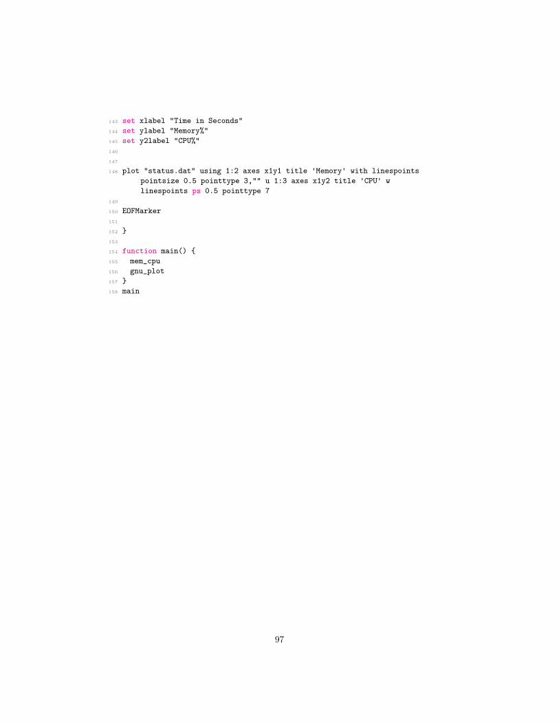
143 set xlabel "Time in Seconds"144 set ylabel "Memory%"145 set y2label "CPU%"146
147
148 plot "status.dat" using 1:2 axes x1y1 title 'Memory' with linespointspointsize 0.5 pointtype 3,"" u 1:3 axes x1y2 title 'CPU' wlinespoints ps 0.5 pointtype 7
149
150 EOFMarker151
152 }153
154 function main() {155 mem_cpu156 gnu_plot157 }158 main
97
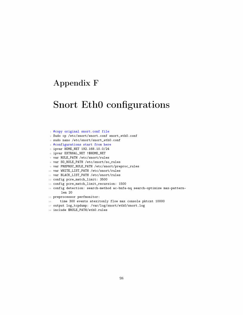
Appendix F
Snort Eth0 configurations
1 #copy original snort.conf file2 Sudo cp /etc/snort/snort.conf snort_eth0.conf3 sudo nano /etc/snort/snort_eth0.conf4 #configurations start from here5 ipvar HOME_NET 192.168.10.0/246 ipvar EXTRNAL_NET !$HOME_NET7 var RULE_PATH /etc/snort/rules8 var SO_RULE_PATH /etc/snort/so_rules9 var PREPROC_RULE_PATH /etc/snort/preproc_rules
10 var WHITE_LIST_PATH /etc/snort/rules11 var BLACK_LIST_PATH /etc/snort/rules12 config pcre_match_limit: 350013 config pcre_match_limit_recursion: 150014 config detection: search-method ac-bnfa-nq search-optimize max-pattern-
len 2015 preprocessor perfmonitor:16 time 300 events atexitonly flow max console pktcnt 1000017 output log_tcpdump: /var/log/snort/eth0/snort.log18 include $RULE_PATH/eth0.rules
98

Appendix G
Snort Eth0 Sample Rules
1 # DoS on port 80 rule2 alert tcp $EXTERNAL_NET any -> $HOME_NET 80 (msg:"TCP SYN flood attack
detected on Port 80"; flow: stateless; flags:S,12; threshold: typethreshold, track by_dst, count 1000, seconds 5; classtype: attempted-recon; sid:10002; rev:1;)
3 # Rule for detecting BlackNurse attack4 alert icmp $EXTERNAL_NET any -> $HOME_NET any (msg:"TDC-SOC-Possible
BlackNurse attack from external source"; itype:3; icode:3;detection_filter:track by_dst,count 250, seconds 1; priority:3; sid:88000012; rev:1;)
5
6 # Telnet/Botnet traffic detection rule7 alert tcp $EXTERNAL_NET any -> $HOME_NET [23,2323,3323,4323] (msg:"ET
TELNET busybox MIRAI hackers - Possible Brute Force Attack"; flow:to_server,established; content:"MIRAI"; flowbits:isset,ET.telnet.busybox; threshold: type limit, count 1, track by_src, seconds 30;reference:url,lists.emergingthreats.net/pipermail/emerging-sigs/2016-August/027524.html; classtype:attempted-admin; sid:2023019;rev:2; metadata:attack_target Server, deployment Datacenter,signature_severity Major, created_at 2016_08_08, performance_impactLow, updated_at 2016_09_26;)
8 # Port scan rule i.e. XMAS Tree scan9 alert tcp any any -> $HOME_NET any (msg:"Nmap XMAS Tree Scan"; flags:FPU;
sid:10000006; rev:1; )10 # SSH dictionary attacks11 alert tcp $EXTERNAL_NET any -> $HOME_NET 22 (msg:"INDICATOR-SCAN SSH
brute force login attempt"; flow:to_server,established; content:"SSH-"; depth:4; detection_filter:track by_src, threshold: typethreshold, count 10, seconds 5;metadata:service ssh; classtype:misc-activity; sid:19559; rev:5;)
99