build your own portable usb charger create the portable usb charger you need to solder 9 components...
TRANSCRIPT
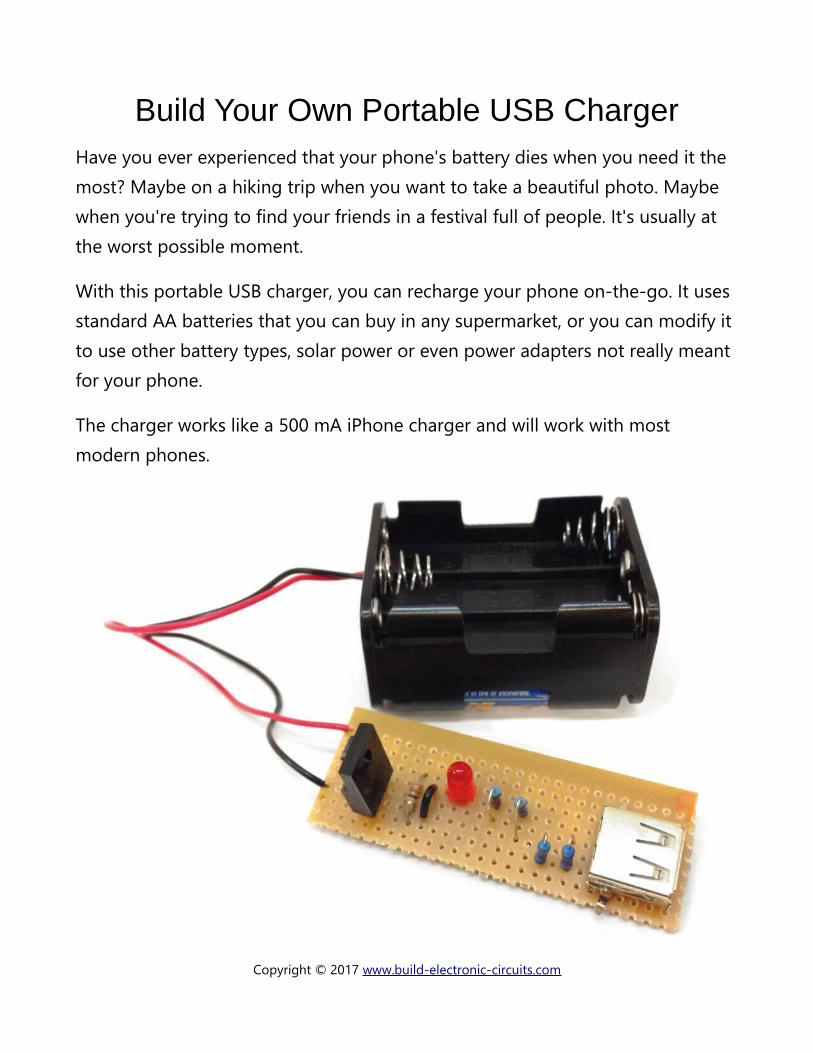
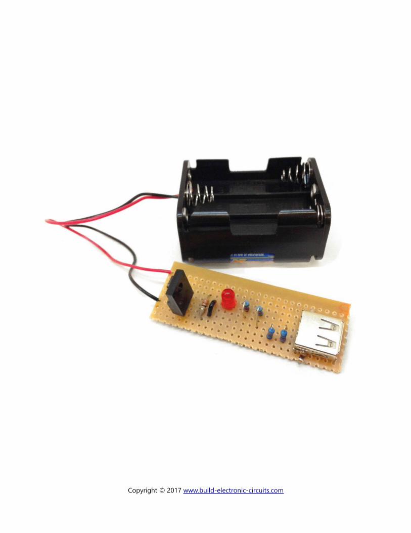
Build Your Own Portable USB ChargerHave you ever experienced that your phone's battery dies when you need it the most? Maybe on a hiking trip when you want to take a beautiful photo. Maybe when you're trying to find your friends in a festival full of people. It's usually at the worst possible moment.
With this portable USB charger, you can recharge your phone on-the-go. It uses standard AA batteries that you can buy in any supermarket, or you can modify it to use other battery types, solar power or even power adapters not really meant for your phone.
The charger works like a 500 mA iPhone charger and will work with most modern phones.
Copyright © 2017 www.build-electronic-circuits.com
How To Build The CircuitTo create the Portable USB Charger you need to solder 9 components onto a board. If you're an experienced circuit builder, this should be a piece of cake. If you're a beginner, it should be a nice challenge that you'll learn a lot from.
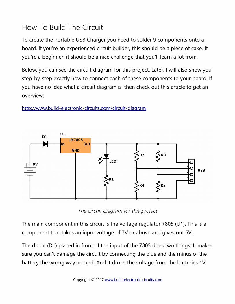
Below, you can see the circuit diagram for this project. Later, I will also show you step-by-step exactly how to connect each of these components to your board. Ifyou have no idea what a circuit diagram is, then check out this article to get an overview:
http://www.build-electronic-circuits.com/circuit-diagram
The circuit diagram for this project
The main component in this circuit is the voltage regulator 7805 (U1). This is a component that takes an input voltage of 7V or above and gives out 5V.
The diode (D1) placed in front of the input of the 7805 does two things: It makessure you can't damage the circuit by connecting the plus and the minus of the battery the wrong way around. And it drops the voltage from the batteries 1V
Copyright © 2017 www.build-electronic-circuits.com
down, from 9V to 8V, which helps take some heat away from the voltage regulator.
The Light-Emitting Diode (LED) is there to show you when the charger is working. The resistor R1 makes sure the LED doesn't have too much current flowing through it. The resistors (R2-R5) are there to tell your phone that this charger supports up to 500 mA (0.5 A) charging.
If you don't know these components and their symbols, check out one of my most popular articles ever:
http://www.build-electronic-circuits.com/basic-electronic-components
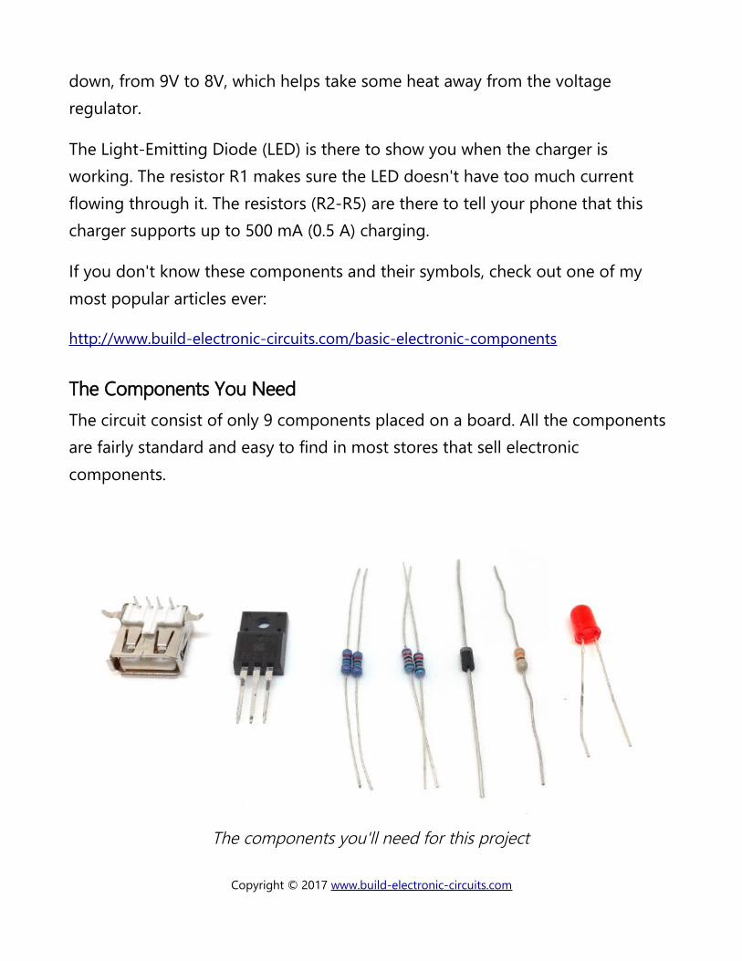
The Components You NeedThe circuit consist of only 9 components placed on a board. All the components are fairly standard and easy to find in most stores that sell electronic components.
The components you'll need for this project
Copyright © 2017 www.build-electronic-circuits.com
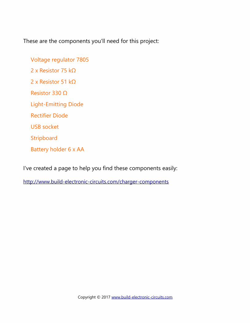
These are the components you'll need for this project:
Voltage regulator 7805
2 x Resistor 75 kΩ
2 x Resistor 51 kΩ
Resistor 330 Ω
Light-Emitting Diode
Rectifier Diode
USB socket
Stripboard
Battery holder 6 x AA
I've created a page to help you find these components easily:
http://www.build-electronic-circuits.com/charger-components
Copyright © 2017 www.build-electronic-circuits.com
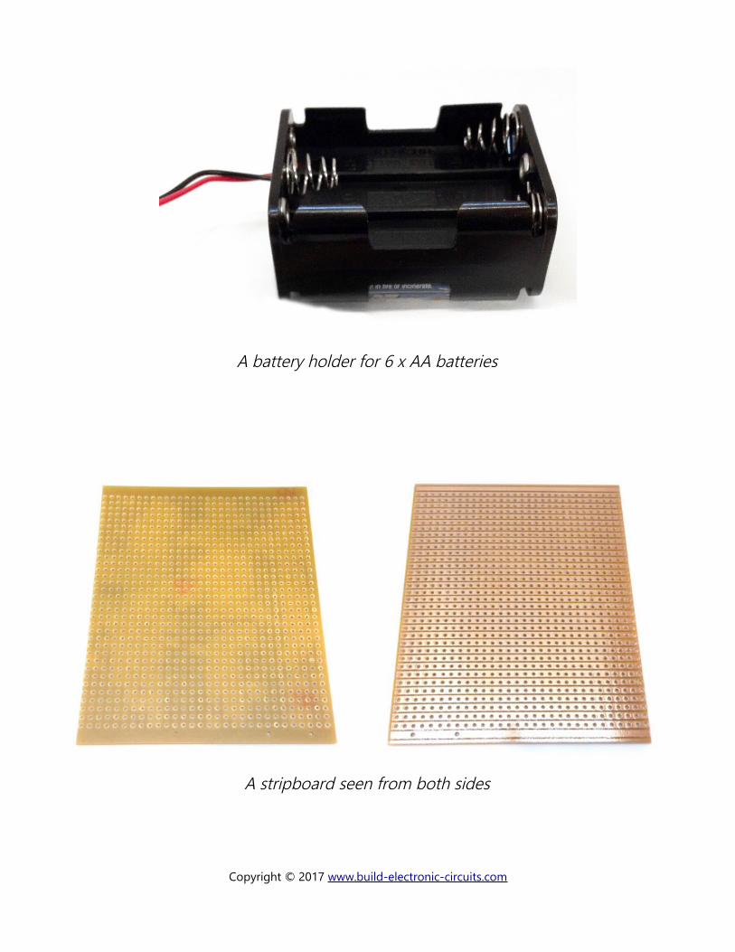
A battery holder for 6 x AA batteries
A stripboard seen from both sides
Copyright © 2017 www.build-electronic-circuits.com
The Tools You NeedTo build this project, all you really need is a soldering iron, some solder and a wire cutter. A soldering iron does not have to be expensive. You can find a fully functional soldering iron for less than $10. Click on the link below to find for some recommendations on what to get:
http://www.build-electronic-circuits.com/soldering-tools
In addition you need something for cutting the copper lines. But this could be something as simple as a pocket knife, a screw bit, or some scissors.
Copyright © 2017 www.build-electronic-circuits.com
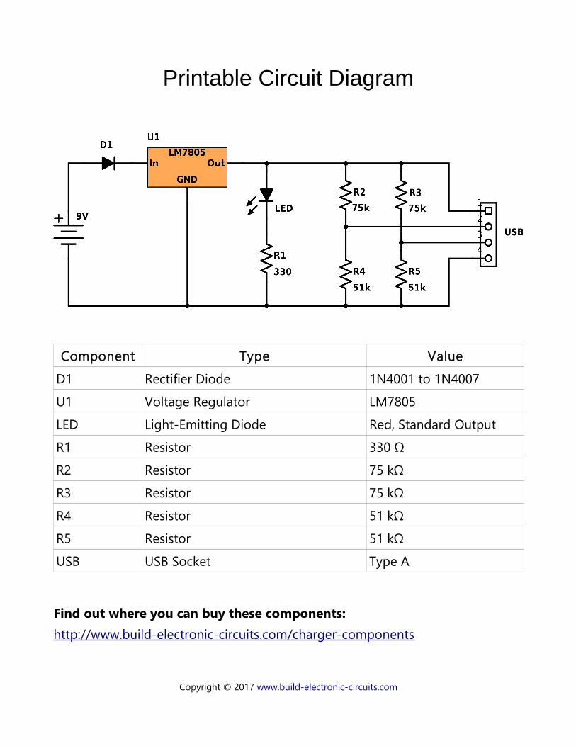
Printable Circuit Diagram
Component Type Value
D1 Rectifier Diode 1N4001 to 1N4007
U1 Voltage Regulator LM7805
LED Light-Emitting Diode Red, Standard Output
R1 Resistor 330 Ω
R2 Resistor 75 kΩ
R3 Resistor 75 kΩ
R4 Resistor 51 kΩ
R5 Resistor 51 kΩ
USB USB Socket Type A
Find out where you can buy these components:http://www.build-electronic-circuits.com/charger-components
Copyright © 2017 www.build-electronic-circuits.com
Build The Portable USB ChargerIt's time to start building. In this section I will show you step by step how to build the project. I recommend you first browse through all the steps quickly, mainly just looking at the pictures, so that you'll have an idea of the steps you need to do.
None of these steps are particularly complicated. But, if you're a beginner I recommend you double check all your component placements before soldering. Also keep in mind that for all components except the resistor, it matters which leg is on which side.
Copyright © 2017 www.build-electronic-circuits.com
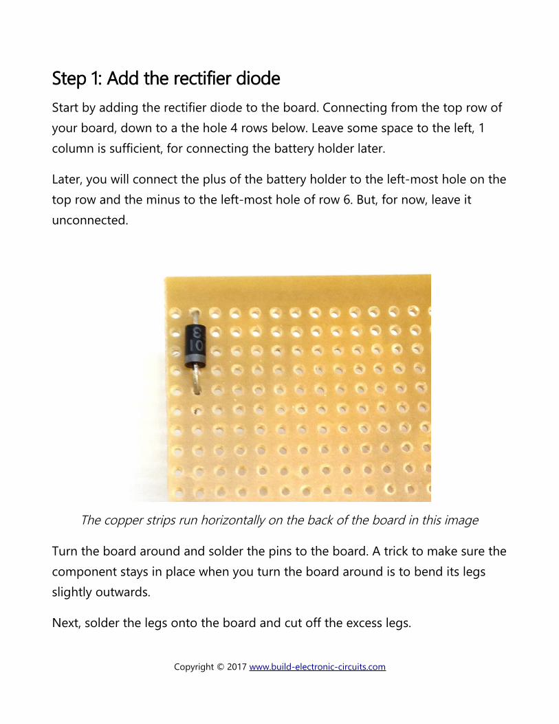
Step 1: Add the rectifier diodeStart by adding the rectifier diode to the board. Connecting from the top row of your board, down to a the hole 4 rows below. Leave some space to the left, 1 column is sufficient, for connecting the battery holder later.
Later, you will connect the plus of the battery holder to the left-most hole on thetop row and the minus to the left-most hole of row 6. But, for now, leave it unconnected.
The copper strips run horizontally on the back of the board in this image
Turn the board around and solder the pins to the board. A trick to make sure thecomponent stays in place when you turn the board around is to bend its legs slightly outwards.
Next, solder the legs onto the board and cut off the excess legs.
Copyright © 2017 www.build-electronic-circuits.com
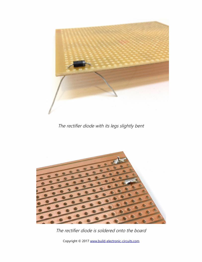
The rectifier diode with its legs slightly bent
The rectifier diode is soldered onto the board
Copyright © 2017 www.build-electronic-circuits.com
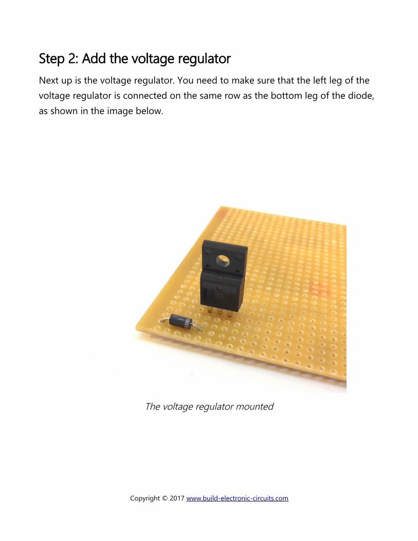
Step 2: Add the voltage regulatorNext up is the voltage regulator. You need to make sure that the left leg of the voltage regulator is connected on the same row as the bottom leg of the diode, as shown in the image below.
The voltage regulator mounted
Copyright © 2017 www.build-electronic-circuits.com
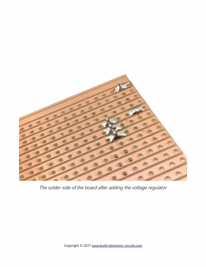
The solder-side of the board after adding the voltage regulator
Copyright © 2017 www.build-electronic-circuits.com
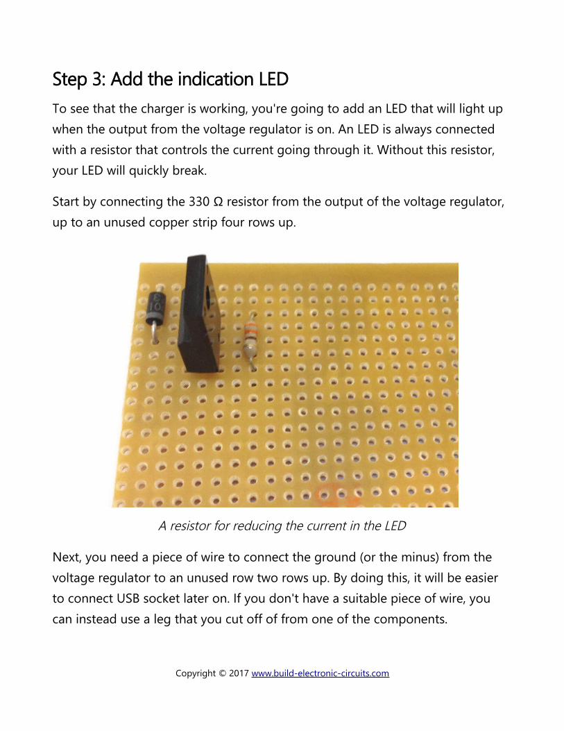
Step 3: Add the indication LEDTo see that the charger is working, you're going to add an LED that will light up when the output from the voltage regulator is on. An LED is always connected with a resistor that controls the current going through it. Without this resistor, your LED will quickly break.
Start by connecting the 330 Ω resistor from the output of the voltage regulator, up to an unused copper strip four rows up.
A resistor for reducing the current in the LED
Next, you need a piece of wire to connect the ground (or the minus) from the voltage regulator to an unused row two rows up. By doing this, it will be easier to connect USB socket later on. If you don't have a suitable piece of wire, you can instead use a leg that you cut off of from one of the components.
Copyright © 2017 www.build-electronic-circuits.com
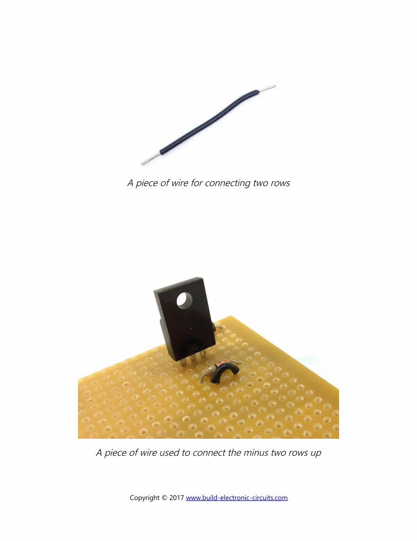
A piece of wire for connecting two rows
A piece of wire used to connect the minus two rows up
Copyright © 2017 www.build-electronic-circuits.com
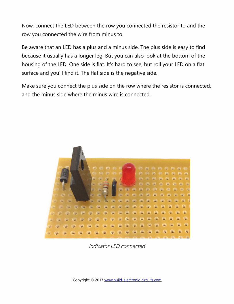
Now, connect the LED between the row you connected the resistor to and the row you connected the wire from minus to.
Be aware that an LED has a plus and a minus side. The plus side is easy to find because it usually has a longer leg. But you can also look at the bottom of the housing of the LED. One side is flat. It's hard to see, but roll your LED on a flat surface and you'll find it. The flat side is the negative side.
Make sure you connect the plus side on the row where the resistor is connected,and the minus side where the minus wire is connected.
Indicator LED connected
Copyright © 2017 www.build-electronic-circuits.com
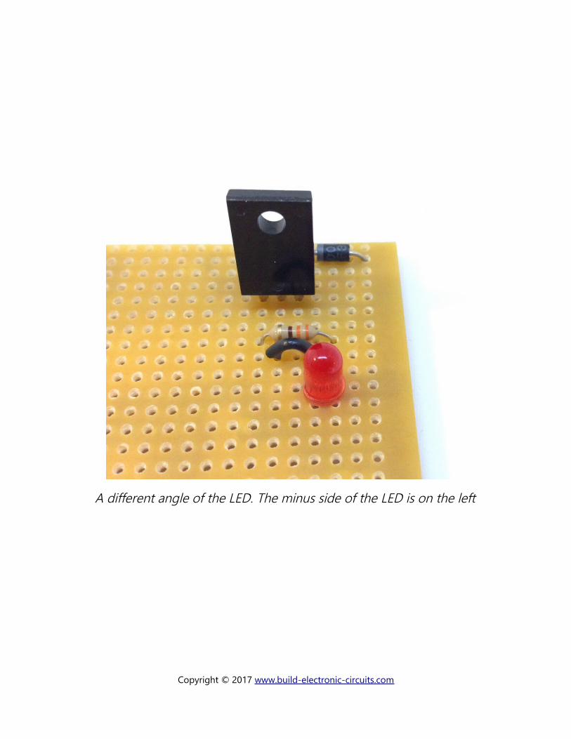
A different angle of the LED. The minus side of the LED is on the left
Copyright © 2017 www.build-electronic-circuits.com
Step 4: Break copper stripsNow, you have built the “power supply”-part of this circuit. You can connect a battery holder with 9V on the input and get 5V on the output.
But, for a USB charger you need a bit more. The reason for this is that the deviceneeds to know how much current the charger can give as a maximum. Some chargers can supply 2.1A of current, while others can only supply 500 mA. The device needs to know, so that it can charge with the correct rate.
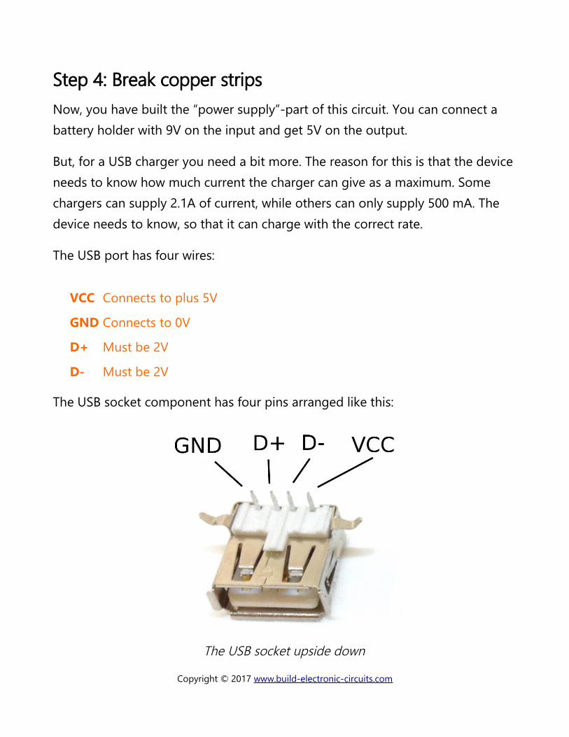
The USB port has four wires:
VCC Connects to plus 5V
GND Connects to 0V
D+ Must be 2V
D- Must be 2V
The USB socket component has four pins arranged like this:
The USB socket upside down
Copyright © 2017 www.build-electronic-circuits.com
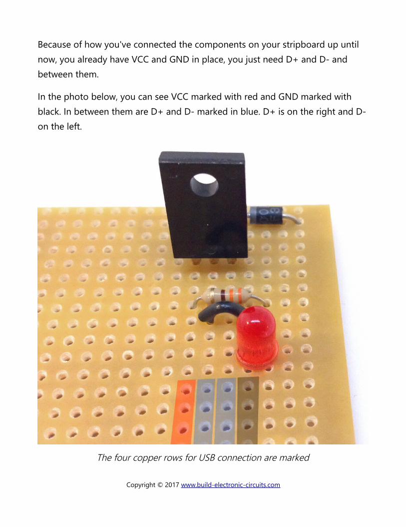
Because of how you've connected the components on your stripboard up until now, you already have VCC and GND in place, you just need D+ and D- and between them.
In the photo below, you can see VCC marked with red and GND marked with black. In between them are D+ and D- marked in blue. D+ is on the right and D-on the left.
The four copper rows for USB connection are marked
Copyright © 2017 www.build-electronic-circuits.com
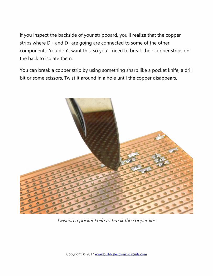
If you inspect the backside of your stripboard, you'll realize that the copper strips where D+ and D- are going are connected to some of the other components. You don't want this, so you'll need to break their copper strips on the back to isolate them.
You can break a copper strip by using something sharp like a pocket knife, a drillbit or some scissors. Twist it around in a hole until the copper disappears.
Twisting a pocket knife to break the copper line
Copyright © 2017 www.build-electronic-circuits.com
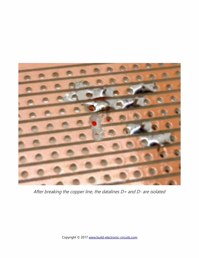
After breaking the copper line, the datalines D+ and D- are isolated
Copyright © 2017 www.build-electronic-circuits.com
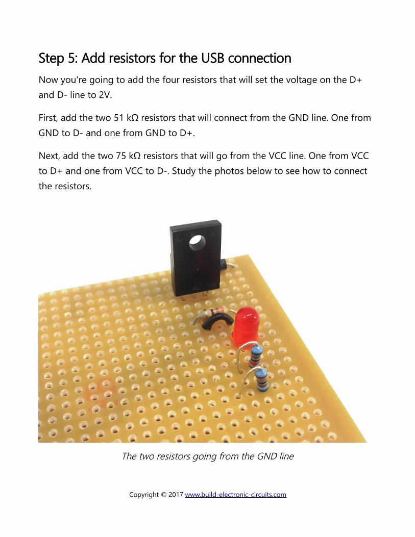
Step 5: Add resistors for the USB connectionNow you're going to add the four resistors that will set the voltage on the D+ and D- line to 2V.
First, add the two 51 kΩ resistors that will connect from the GND line. One from GND to D- and one from GND to D+.
Next, add the two 75 kΩ resistors that will go from the VCC line. One from VCC to D+ and one from VCC to D-. Study the photos below to see how to connect the resistors.
The two resistors going from the GND line
Copyright © 2017 www.build-electronic-circuits.com
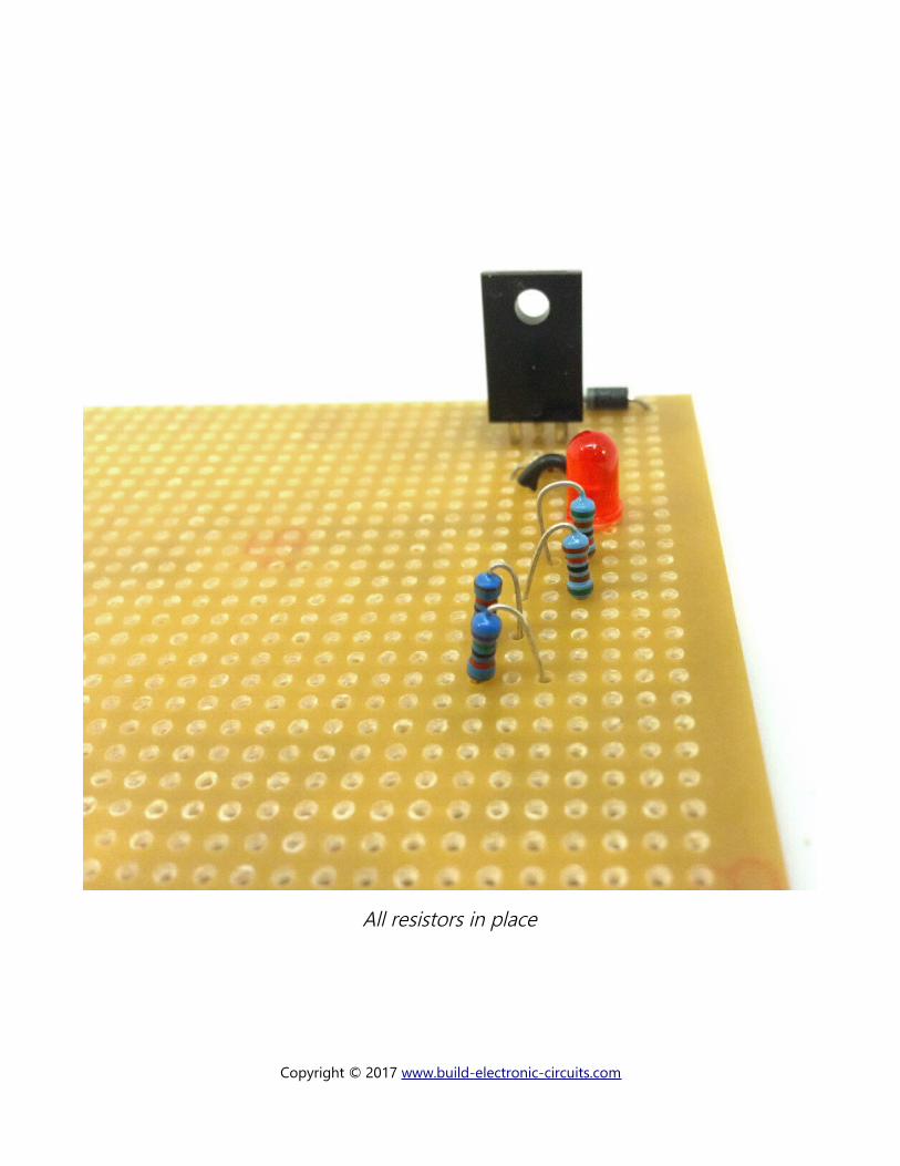
All resistors in place
Copyright © 2017 www.build-electronic-circuits.com
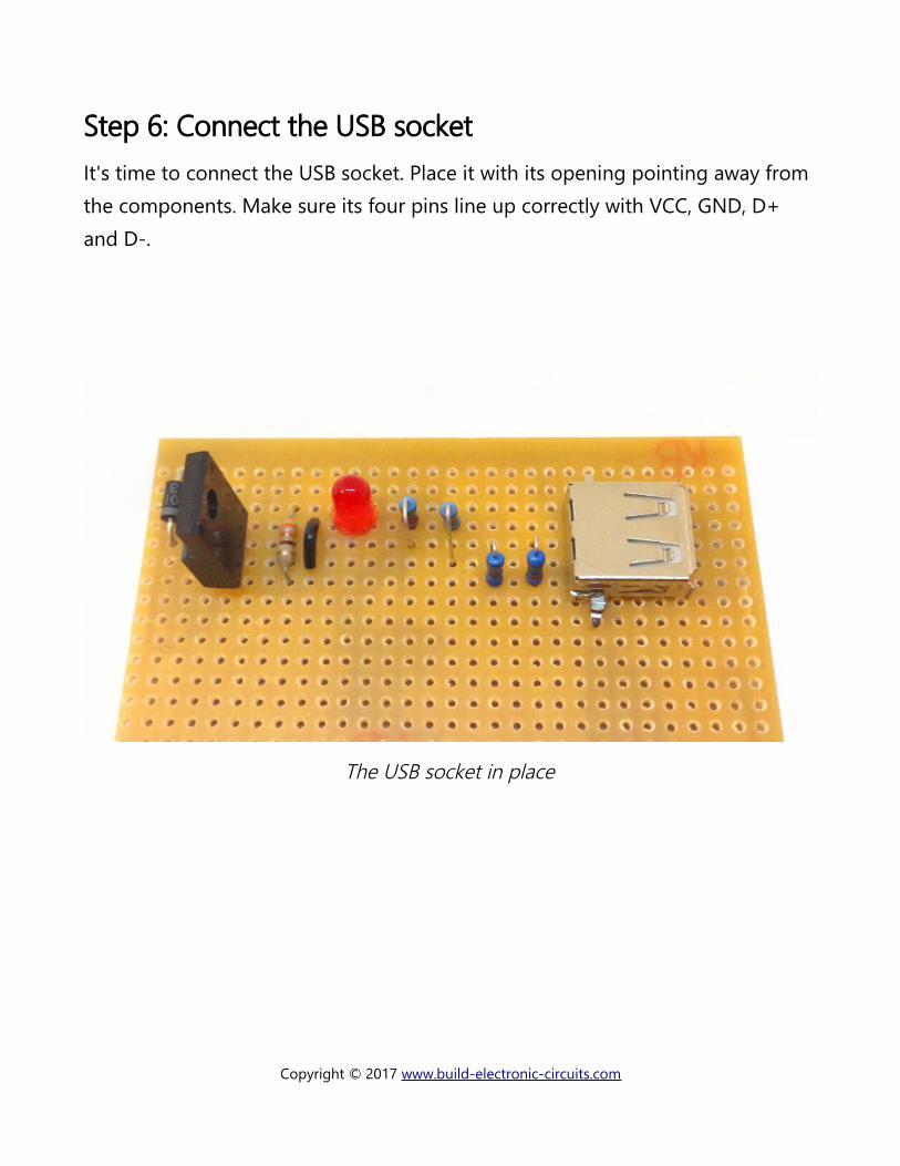
Step 6: Connect the USB socketIt's time to connect the USB socket. Place it with its opening pointing away from the components. Make sure its four pins line up correctly with VCC, GND, D+ and D-.
The USB socket in place
Copyright © 2017 www.build-electronic-circuits.com
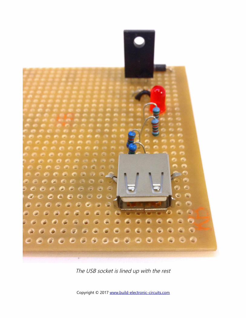
The USB socket is lined up with the rest
Copyright © 2017 www.build-electronic-circuits.com
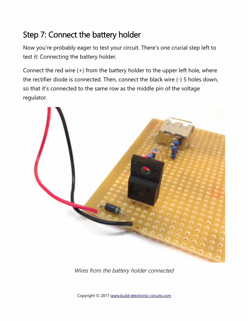
Step 7: Connect the battery holderNow you're probably eager to test your circuit. There's one crucial step left to test it: Connecting the battery holder.
Connect the red wire (+) from the battery holder to the upper left hole, where the rectifier diode is connected. Then, connect the black wire (-) 5 holes down, so that it's connected to the same row as the middle pin of the voltage regulator.
Wires from the battery holder connected
Copyright © 2017 www.build-electronic-circuits.com
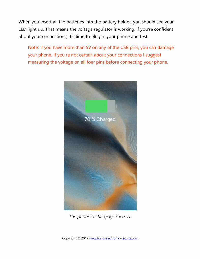
When you insert all the batteries into the battery holder, you should see your LED light up. That means the voltage regulator is working. If you're confident about your connections, it's time to plug in your phone and test.
Note: If you have more than 5V on any of the USB pins, you can damage your phone. If you're not certain about your connections I suggest measuring the voltage on all four pins before connecting your phone.
The phone is charging. Success!
Copyright © 2017 www.build-electronic-circuits.com
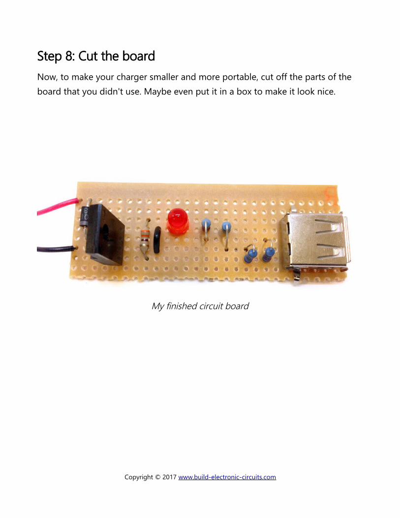
Step 8: Cut the boardNow, to make your charger smaller and more portable, cut off the parts of the board that you didn't use. Maybe even put it in a box to make it look nice.
My finished circuit board
Copyright © 2017 www.build-electronic-circuits.com
Copyright © 2017 www.build-electronic-circuits.com
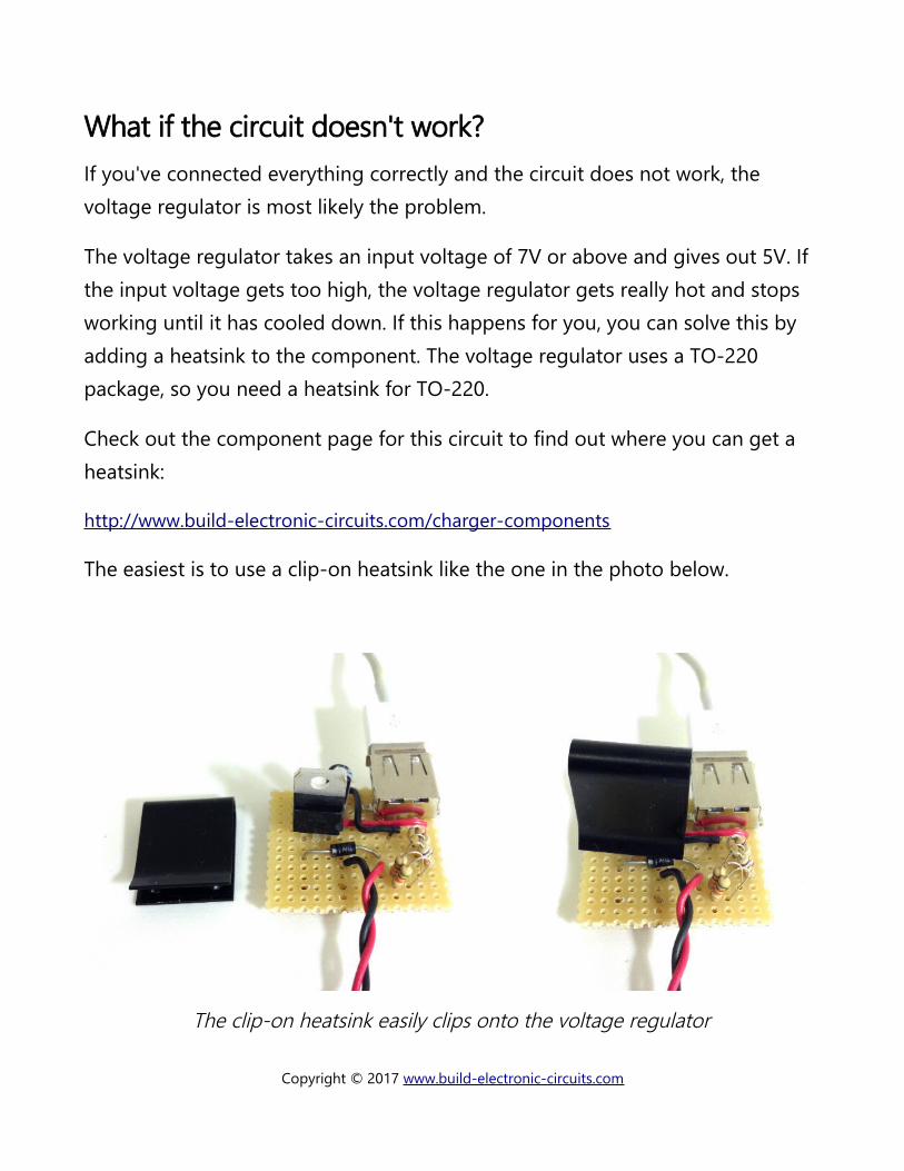
What if the circuit doesn't work?If you've connected everything correctly and the circuit does not work, the voltage regulator is most likely the problem.
The voltage regulator takes an input voltage of 7V or above and gives out 5V. If the input voltage gets too high, the voltage regulator gets really hot and stops working until it has cooled down. If this happens for you, you can solve this by adding a heatsink to the component. The voltage regulator uses a TO-220 package, so you need a heatsink for TO-220.
Check out the component page for this circuit to find out where you can get a heatsink:
http://www.build-electronic-circuits.com/charger-components
The easiest is to use a clip-on heatsink like the one in the photo below.
The clip-on heatsink easily clips onto the voltage regulator
Copyright © 2017 www.build-electronic-circuits.com
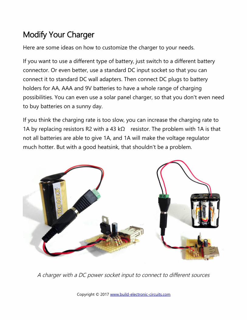
Modify Your ChargerHere are some ideas on how to customize the charger to your needs.
If you want to use a different type of battery, just switch to a different battery connector. Or even better, use a standard DC input socket so that you can connect it to standard DC wall adapters. Then connect DC plugs to battery holders for AA, AAA and 9V batteries to have a whole range of charging possibilities. You can even use a solar panel charger, so that you don't even needto buy batteries on a sunny day.
If you think the charging rate is too slow, you can increase the charging rate to 1A by replacing resistors R2 with a 43 k resistor. The problem with 1A is that Ωnot all batteries are able to give 1A, and 1A will make the voltage regulator much hotter. But with a good heatsink, that shouldn't be a problem.
A charger with a DC power socket input to connect to different sources
Copyright © 2017 www.build-electronic-circuits.com
What's Next?If you enjoyed building this circuit, I highly recommend you check out my electronics builder club Ohmify. It's full of projects like this, where you get to build something useful. But, it's also full of courses on how electronics work so that you can create your own inventions too!
Whether you want to build an automatic cat door for your house or the next must-have gadget for the world, there are some steps you need to take to build up the skills and knowledge necessary to build your own inventions with electronics.
To help people from all backgrounds learn these steps, I’ve created Ohmify. It’s an online electronics builders club with lots of courses and resources to learn electronics such as:
• 25+ courses on skills such as soldering, Arduino programming, basic electronics and more.
• Step-by-step instructions for cool projects like a robot, music player and the Atari Punk Console
• Roadmaps that show you what the next step is for you, depending on yourbackground.
• Forum for discussing ideas, asking questions and getting un-stuck with your projects.
Learn more about Ohmify here:
https://ohmify.com/join
Copyright © 2017 www.build-electronic-circuits.com