btu meter / data logger - noncontact meters · 4 1. product description the btum is a...
TRANSCRIPT

1
BTU Meter / Data Logger User Manual
November 2014 Ver. 1.02.04

2
Table of contents
Quick Start 3
1.Product description / Technical data 4
2. Installation 6
2.2 Connections 6
2.2.1 Installing RTDs 7
2.2.2 Programming 8
2.3. micro SD card installation 8
3.1. Power up 9
3.2.Data logging on the micro-SD card 9
3.3.Reading data using PC software 9
4.1.Unit setup 12
4.2.SD card logging setting 14
4.3New unit configuration 16
4.4 Reset 17
5.Real-Time data acquisition 18
Warranty 19
Terms 20
Drawings 21
Appendix

3
QUICK START
Every new unit is preset with factory default values but some of them need to be
individually set for each BTUM unit.
To set data for the new BTUM unit proceed as follows: • Scale Flow meter 4/20mA output • Connect Flow meter output to BTUM • Install two RTDs • Connect the power (Caution A/C Power) • Connect the USB cable. • Run BTUMCONFIG program, • Select “Setting” from the Main Menu and “Retrieve from Meter” • Modify the flowmeter GPM values for 4mA and 20mA signal (manufacturer data) • Set BTUM unit Date and Time • Change screen to µSD card Logging • Select data to be logged on the SD card, their order and Header • Selecting “Setting” from the Main Menu and “Upload to meter” • If not already installed, insert formatted µSD card. • Log data, indicated by LED-D6 blinking when writing to µSD card. • To retrieve logged data, remove power when opening enclosure and remove µSD card and install into PC for viewing in excel

4
1. Product description
The BTUM is a microprocessor based instrument designed to measure and log the energy
consumption for heating and cooling installations. Additionally it provides the current energy
and flow rates and temperatures on the supply and return lines.
The two temperature inputs are 3-wire 100Ω RTD’s. The flow sensor can accommodate any
4-20 mA flowmeter. The 24VDC/120 mA is available on-board to power the flowmeter. Output
includes a pulse output based on energy or flow consumption.
Data can be logged on on-board micro-SD card in .CSV format. Alternatively the data can be
configured using Windows based software via USB port (BTUMCONF.exe).
The BTUM unit can be purchased as a complete kit with flowmeter and 2 RTD's temperature
sensors, factory programmed, calibrated and ready for use upon delivery.
The unit is factory pre-programmed but may need a few steps setup if not ordered as a complete kit as described in summary. 1.1. Technical Data P/N: BTUM-A1 Power Supply 110VAC Power failure detection to save data Flow Sensor 4-20 mA 24VDC/120 mA power available for the flow meter. Temperature Sensor RTD 3-wire 100 ohms
Output NPN open collector. Max. voltage: 24VDC Communication USB port, Proprietary protocol Function: read data, configuration, calibration Operating Temp Enclosure/Logger -20 to 60°C (-4 to 140°F)
Dimensions 130mm x 74mm x 50mm (5.12” x 2.91” x 1.97”) Wall mount NEMA IP54 enclosure
Flow Input 4-20 mA signal VDC/120mA power available Units of measure: GPM, Gal/hr, Gal/sec, l/sec, l/min, l/hr,m3/hr Temperature Two 3-wire platinum 100 Ω RTD Units of measure: °C and °F Range: 0°C to 100°C (32°F to 212°F)
Resolution: 0.1°C (0.18°F) Accuracy: ±1°C with matched RTD’s Calibration: 2 points individually for each RTD

5
Operation Heating or Cooling Calculated Power Units: BTU/hr, kBTU/hr, kW, MW, Ton, kTon, MTon, J/sec Total Energy Units: kBTU, kWh, MWh, Ton*hr, kTon*hr, MTon*hr, MJ
Overall total Total Energy is periodically saved in internal EEPROM so these values are maintained in case of power failure or power disconnecting.
Total Flow Units: Gallons, liters, m3 Overall total Total Flow is periodically saved in internal EEPROM so these values are maintained in case of power failure or power disconnecting. Pulse output NPN open collector
Max. voltage: 24VDC Can be configured as Energy or Flow totalizer Rate: 1 pulse per number of currently used units Pulse duration: 1ms to 10 seconds
Communication USB Type B receptacle (cable included) Proprietary protocol, may need to install the USB driver Functions: Configuration, calibration, data collection and logging
Data Logging Micro-SD card saves in .CSV format SD card formatting on the PC computer using supplied configuration software Sample rates set using the PC configuration software.
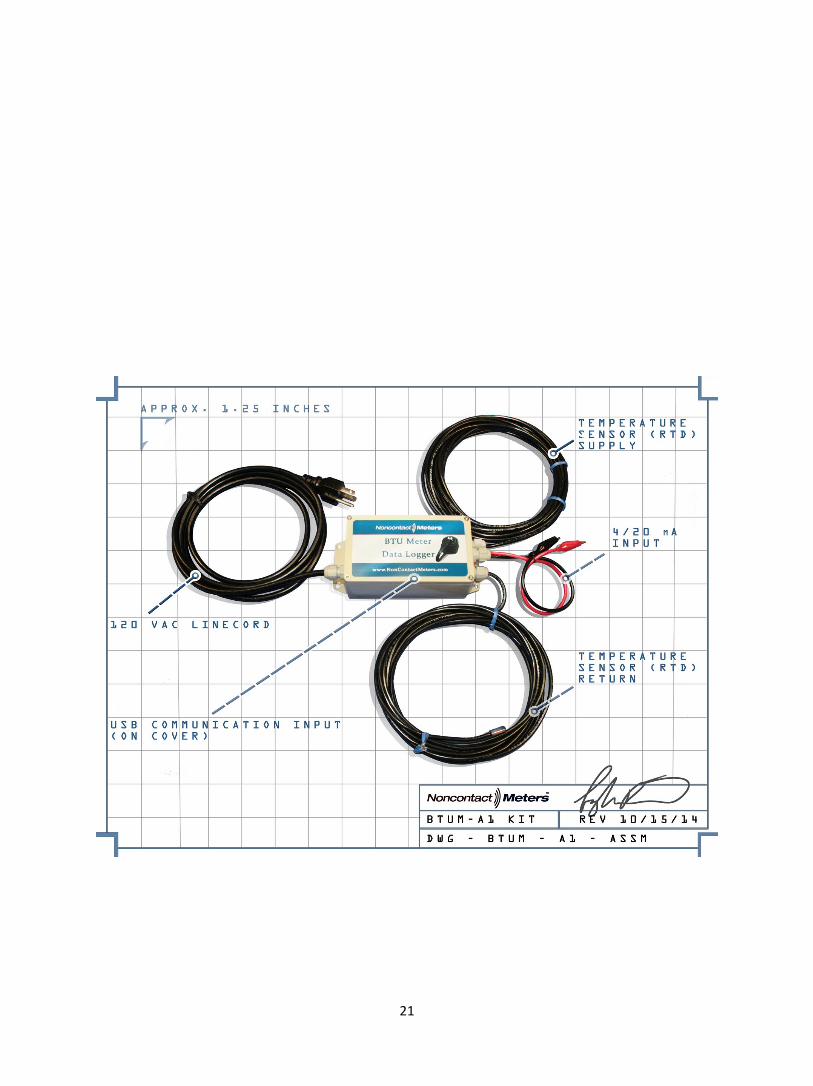
Summary P/N: BTUM-A1 (Kit) Includes: Data Logger Pair 100 ohm strap-on RTDs with 100 ft of cable Line cord Thermo compound PN# NMC-8000 Mounting tape PN# NCM-8100 Configuration Software – Download (Free) Configuration Software – USB Flash drive P/N# NCM-8500 Micro SD card 2GB PN#NCM-8200 Micro SD to USB Reader PN#NCM-8250 USB communication cable PN#NCM-8300 Screw Driver PN# NCM-8600

6
2. Installation
2.1. Panel mounting
The BTUM unit can be mounted on any wall surface (concrete, metal, wood) using
appropriate screws according to the local law regulations. The unit should be
located, if possible, for easy access for service. The unit should not be exposed to
ambient temperatures below -20°C (-4°F), and above 60°C (140°F). It is preferable
the unit is not installed close to high voltage wires and other sources of high
electrical noise.
2.2. Connections
The unit comes assembled with the line cord, RTDs and 4/20mA input cable
(Alligator clips) and USB connector on the cover. If you wish to hardware your
installation, turn off the 120 VAC power or unplug the line cord. The unit
requires two RTD temperature sensors (connectors P4 and P5) and a one 4-20mA
flowmeter to connector P1. Corresponding connectors are shown on figure below.
Connect the 110VAC cable power supply to P2 connector.

7
2.2.1 Installing Temperature sensors (RTDs)
The RTDs come as a pair with 20 ft of cable. Attach the RTDs to a metal pipe surface
as illustrated bellow using thermo compound and mounting tape. One on the supply
line and the other on the return line.
Mount the RTD – temperature sensors in the identical location on the supply and the return (metal) pipes. Failure to-do so will result in temperature differentials that can affect your performance of the BTU calculations.

8
2.2.2 Programming your flow meter
You can use any type of flow meter that has a 4/20mA output signal. Mount or install
your flow meter on the supply line. Now you will need to take note of the 4/20mA scale
that is on your flow meter. Or, if you have to program your flow meter to assign a flow
rate at 4mA and your full scale at 20mA. If you don’t have a preference, the standard is
to program your full scale to 10 fps (feet per second). If you need a quick reference use
this equation FPS TO GPM: GPM = (PIPE ID)2 X VELOCITY IN FPS X 2.45.
Connect your flow meter 4/20mA output with signal wire to the BTUM logger 4/20mA
input (Alligator clips) or open the enclosure and hard wire. Note. turn off or unplug
power when opening up the enclosure.
The BTUM red wire is Positive and the black wire is negative.
2.3. micro-SD card installation
The unit comes with a Micro Sd card installed. If you need to install or remove another
turn off the power or unplug. To install insert the micro-SD card as shown on fig. 2.
Place the card on the right of the SD card socket and push it inside until you can hear
the click. To remove the card push the card to the left and remove it with your fingers.
There is a red LED on the left of the SD card socket. The LED goes ON during the
writing. NEVER REMOVE THE SD CARD WHEN THE LED IS ON. The
best way to operate is to wait for the LED goes ON and remove the card after the LED
is OFF.
IMPORTANT: you can use only micro-SD cards supplied with the BTUM unit specially
formatted. Contact us for details.

9
3. Startup
3.1. Power up
The BTUM unit starts to operate as soon as the power supply is connected. If the BTUM unit
cover is opened you can see the both LEDs going ON and OFF. The normal cycle of
operation starts then the ‘Data Reading LED” (see fig. 1) is flashing regularly (every one
second). The data acquisition (temperatures and flow) are made then the LED change his
stage. Note: you still need to program the BTUM with your PC or laptop for a comprehensive
log.
Note: For safe operation of this logger, turnoff power or unplug the line cord before you open
the enclosure.
3.2. Data logging on the micro-SD card
Selected data (see paragraph 4.2 for more details) are saved periodically on the SD card.
Data are saved in CSV type files, which can be easily imported to spreadsheet programs.
The BTUM has a build-in Real-Time Clock and data are all logged data are saved in
monthly files. The name will have a following format YYMM-NNN.CSV
Where YY – year, MM – month, NNN – unit number.
3.3. Reading data using PC software
Connect the USB type B cable to USB port (on cover) and run
BTUMCONF.exe program on the PC. This program is available as a free
download at www.noncontactmeters.com or www.instrumentsdirect.com .
PC connects automatically with the BTUM unit and downloads Total Energy and Total Flow
values, as well as current Temperatures, Flow and Energy rates and internal meter clock
Date and Time, as shown below.
When running the software for the first
time you may get the ‘No Answer”
message. In this case you need to
select the communication port used by
your computer to communicate with the
BTUM unit. In most case this will be the
port other than COM1. Com port may
vary dependent on computer
configuration.
10
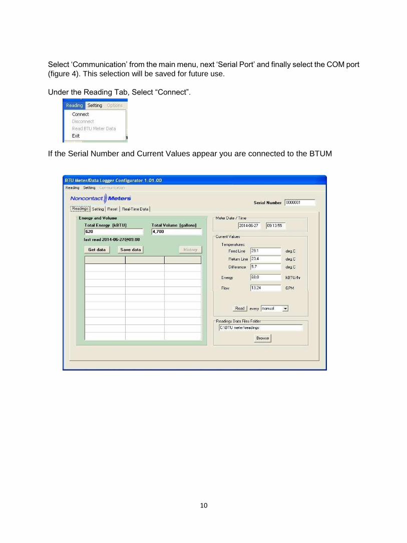
Select ‘Communication’ from the main menu, next ‘Serial Port’ and finally select the COM port
(figure 4). This selection will be saved for future use.
Under the Reading Tab, Select “Connect”.
If the Serial Number and Current Values appear you are connected to the BTUM

11
If you have previous log data, in the “Energy and Volume” section the Total Energy and
Total Volume represents total accumulated values since the last reset .You will get also the
date and time of the last reading.
Total Energy and Total Flow values can be saved on the PC hard drive in the .CSV file, which
can be easily imported to Excel or similar program (press ‘Save data” button). Each BTUM
unit will have his own file named after the unit Serial Number. The folder where BTUM data
should be saved using the ‘Save data” command are pre-configured, but can be change by
the user. Click ‘Browse’ button and select the new folder. Your selection will be saved for
future use.
Current measured and calculated data are displayed
automatically when the BTUMETER program starts and
connects to the BTUM unit. Additionally the user can get new
values by pressing the “Read” button. All these values can be
periodically updated by selecting the reading interval. When
any interval value is selected the READ button will be disabled
and a blue dot will flash every time there is a new reading.
Press “Stop readings” button to end automatic”.
12
4. Setting
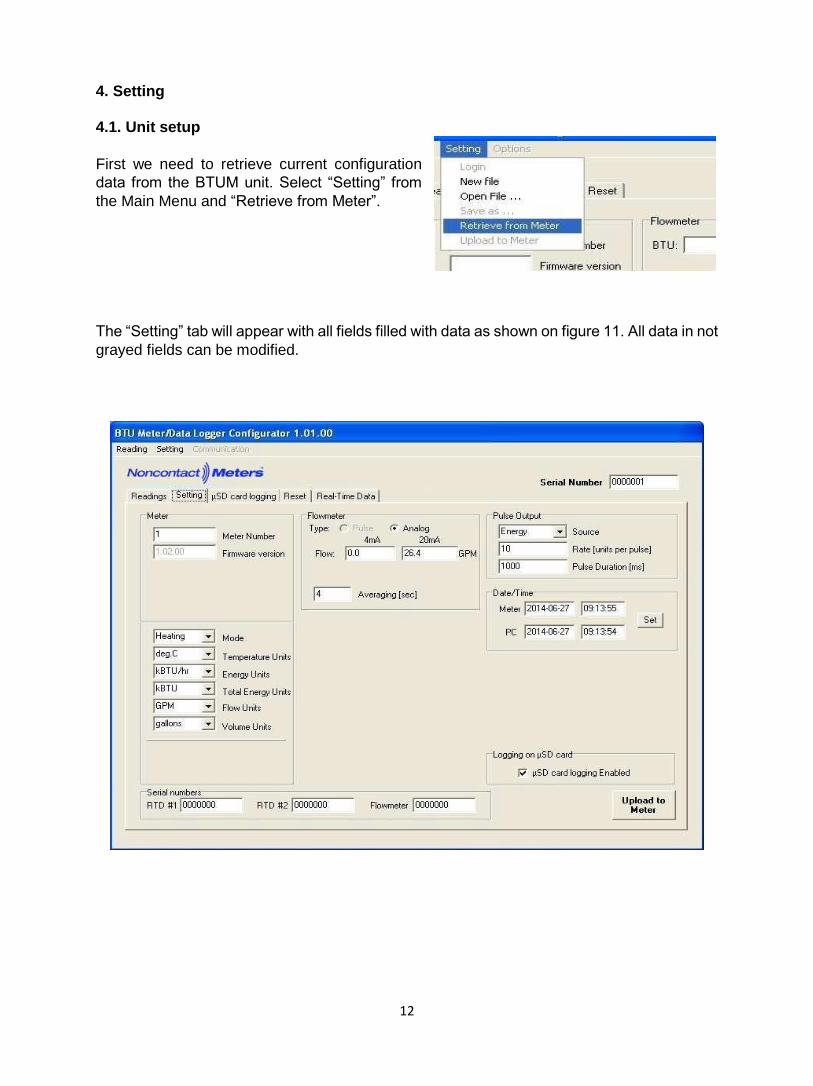
4.1. Unit setup
First we need to retrieve current configuration
data from the BTUM unit. Select “Setting” from
the Main Menu and “Retrieve from Meter”.
The “Setting” tab will appear with all fields filled with data as shown on figure 11. All data in not
grayed fields can be modified.
13
Here are some parameters:
Modified data will not be saved until the “upload to meter button is clicked, located at the
bottom-right side of the screen or by selecting “Setting” from the Main Menu and “Upload to
meter”.
Configuration data can be saved locally on the PC hard drive for future use. Select the
“Setting” from the main menu, next “Save as” and select the name of the file.
Previously saved data can be retrieved form the PC hard drive and uploaded to the BTUM
unit (unchanged or modified) by selecting “Setting” from the Main Menu and “Upload to
meter” .
Special consideration must be made for current BTUM Date and Time. In case of discrepancy
between the BTUM unit and PC computer the Date and Time should be set by pressing the
“Set BTU Meter Date/Time” button.
Meter number Meter number is used for SD card log file names Firmware version Current meter firmware version Mode Heating, Cooling or Heating/Cooling Units Can be selected individually for each parameter Flowmeter Flow limits values are given by the flowmeter manufacturer. Flowmeter aver. Flow measurement averaging time Pulse output Source: energy or flow, pulse rate and duration Date and Time Showing the current BTUM and PC Date and Time µSD card logging Enabling SD data logging. When enabled you will see a new Enabled tab ‘µSD card logging’ for logging configuration.

14
4.2. SD card logging setup
.
Select the µSD card logging tab.
Select the sampling rate. You can select a
value from the pup-up list
You can select which data will be logged on the SD card by checking or un-checking selection
data type boxes .You can also change the order of data in the log file. In order to do this select
the data type to be moved (for example ‘Flow”), next click on the ‘Move Up’ arrow (marked
yellow) until placed on desired position.

15
In order to change log file column headers
click on ‘Download’ button. After modifying
labels click ‘Upload’ button to save them in
BTUM unit EEPROM. Click upload to meter
in the setting drop down list.
To exit from the program, select “reading” from the Main Menu and “Exit”.
16
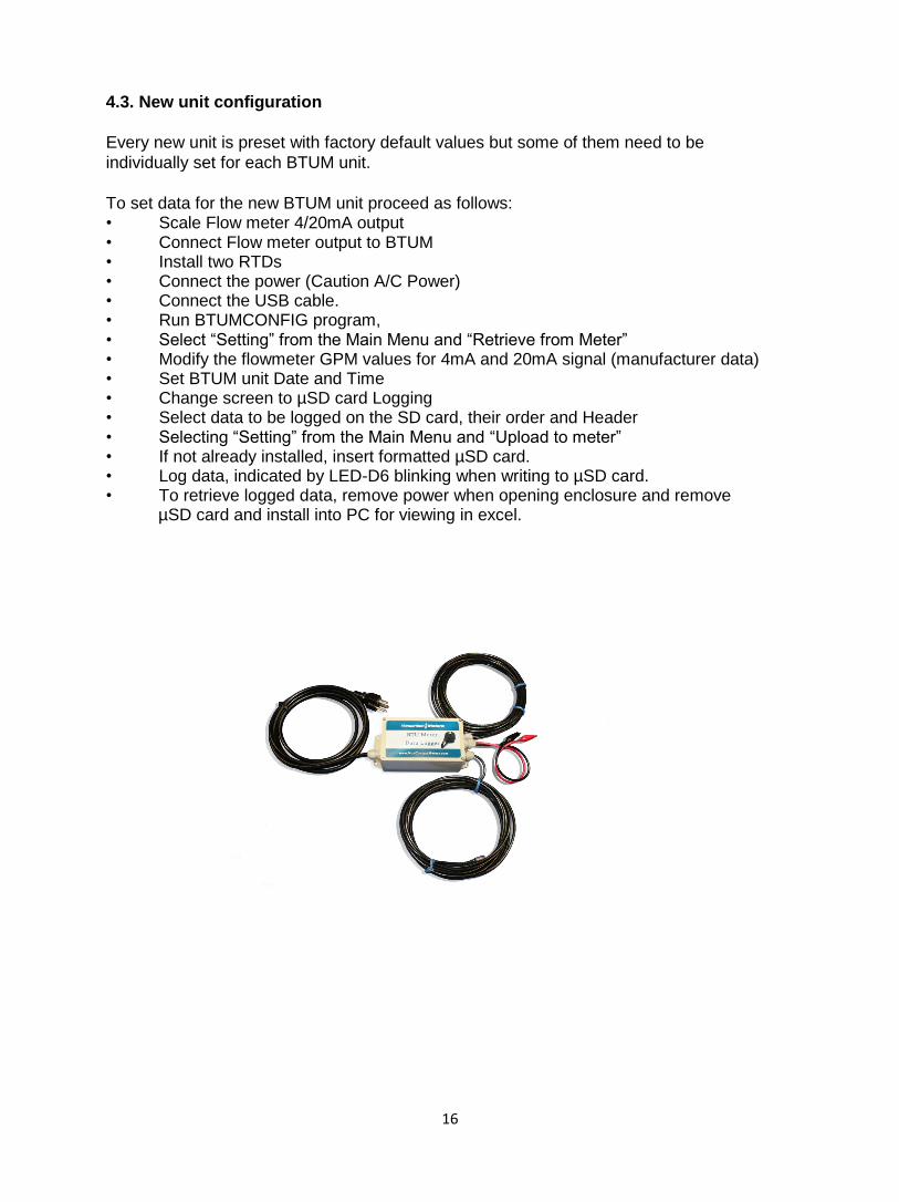
4.3. New unit configuration
Every new unit is preset with factory default values but some of them need to be
individually set for each BTUM unit.
To set data for the new BTUM unit proceed as follows: • Scale Flow meter 4/20mA output • Connect Flow meter output to BTUM • Install two RTDs • Connect the power (Caution A/C Power) • Connect the USB cable. • Run BTUMCONFIG program, • Select “Setting” from the Main Menu and “Retrieve from Meter” • Modify the flowmeter GPM values for 4mA and 20mA signal (manufacturer data) • Set BTUM unit Date and Time • Change screen to µSD card Logging • Select data to be logged on the SD card, their order and Header • Selecting “Setting” from the Main Menu and “Upload to meter” • If not already installed, insert formatted µSD card. • Log data, indicated by LED-D6 blinking when writing to µSD card. • To retrieve logged data, remove power when opening enclosure and remove µSD card and install into PC for viewing in excel.

17
4.4. Reset
Total Energy and Total Volume values can be reset to zeros from the “Reset” tab (figure 16).
These values should be reset by an authorized person.
Select the value you would like to reset (or both) and press “Reset” button. As this action is
irreversible you will need to confirm it twice (figures 16 and 17).
From the same screen you can clear current BTUM unit historical data. This will delete the
corresponding .CSV file (see paragraph 4.0 for details).

18
5. Real-Time data acquisition
This function allows the real-time BTUM data acquisition over a long period of time.
Select “Real-Time Data” tab. Select the folder you would like to save acquired data and data
acquisition frequency. The name of the file is generated automatically from starting date and
time.
Select parameters you would like to save into the file. Optionally you can add a short note.
Press “Start” button to start the acquisition and “Stop” to stop it.
Here is an example of acquired data according to setting from figure
18. Data will be saved in comma separated text files (.CSV) which can be easily imported to
Excel or any other spreadsheet program for.

19
LIMITED WARRANTY AND DISCLAIMER
Noncontact Meters, Inc. warrants to the end purchaser, for a period of one year from the date of
shipment from the factory, that all new transmitters and transducers manufactured by it are free
from defects in materials and workmanship. This warranty does not cover products that have been
damaged due to misapplication, abuse, lack of maintenance, or improper installation. Noncontacts
obligation under this warranty is limited to the repair or replacement of a defective product, at no
charge to the end purchaser, if the product is inspected by Noncontact Meters and found to be
defective. Repair or replacement is at Noncontact Meters discretion. A returned goods
authorization number must be obtained from Noncontact Meters before any product may be
returned for warranty repair or replacement. The product must be thoroughly cleaned and any
process chemicals removed before it will be accepted for return.
The purchaser must determine the applicability of the product for its desired use and assumes all
risks in connection therewith. Noncontact meters assumes no responsibility or liability for any
omissions or errors in connection with the use of its products. Noncontact Meters will under no
circumstances be liable for any incidental, consequential, contingent or special damages or loss to
any person or property arising out of the failure of any product, component or accessory.
All expressed or implied warranties, including the implied warranty of merchantability and the
implied warranty of fitness for a particular purpose or application are expressly disclaimed and
shall not apply to any products sold or services rendered by Noncontact Meters.
The above warranty supersedes and is in lieu of all other warranties, either expressed or implied
and all other obligations or liabilities. No agent or representative has any authority to alter the
terms of this warranty in any way.
Rev 10/11

20
Terms & Conditions Rev 9/28/14
Orders may be placed by phone, fax, mail, email or on our website www.noncontactmeters.com.
Our normal hours of operations are 8:30am to 5pm EST, Monday - Friday and closed on Major Holidays. Phone: 770.516.3999 Fax: 678.445.9993 Email: Sales, Order entry & Customer service: [email protected]
Technical support: [email protected]
Web www.noncontactmeters.com
Mail: Mail Payments, orders and send returns to: Noncontact Meters, Inc
2130 Barrett Park Dr NW,. STE 103 Kennesaw, GA 30144 Note: Published pricing and specifications are subject to change without notice. All prices are FOB Atlanta, GA. USA, unless noted otherwise. All domestic orders are shipped ground UPS or FEDEX prepaid
unless specified otherwise and added to your invoice. If you would prefer to use you own freight account number, please advise this information with your purchase order. A fee will be added for COD or forwarded freight. For rental equipment, reference our RENTAL terms. Terms: Our standard payment terms for domestic orders are Master card, Visa, AMEX or net 30 days with approved credit. We collect taxes for the state of GA. For those companies that are tax exempt
provide a copy of your tax exemption certificate. Rental Terms: (Limited to the continental USA. Contact us about Canadian rental terms)
All rentals are prepaid with AMEX, Master Card or Visa. Noncontact Meters guaranties to provide a calibrated / operational flowmeter per its published specifications. The rental period starts the day of shipment and stops the day it is received back. Weekly terms are for 9 continuous days (7 days plus 2 for shipping). Monthly terms are for 32 continuous days (30 days plus 2 for shipping). If the equipment is not
returned within its defined rental period with will be responsible for an additional rental period. Delivery dates: All critical delivery dates must be confirmed and approved in advance by calling 1-888-722-5543. Rental Returns: Return rental equipment to our facility by the specified due date at your expense, pre-paid and insured to Noncontact Meters, 2130 Barrett Park Dr NW, Ste 130, Kennesaw, GA 30144. International or export terms are prepaid wire transfer and shipped CIF. The buyer is required to complete and submit for approval from BIS-711 required by the U.S Dept of Commerce. Recipient is
responsible for all duty, taxes, inspections & licenses. These products are subject to U.S export control laws including the U.S export administration Act and its associated regulations. Buyer agrees to comply strictly with all regulations and acknowledges that it has the responsibility to obtain licenses to export,
re-export, or import the products. Diversion contrary to U.S. law is prohibited. For additional information contact us Ph 770.516.3999, fx 678.445.9993 or email [email protected]
We take care to fill and check all orders properly. If errors occur please refer to the packing list and contact us immediately. Report shipping damage to the carrier immediately. For returns to Noncontact Meters contact us at 770.516.3999 or email [email protected] for an RMA (Return Material Authorization) number and shipping instructions. Returns are subject to restocking & cleaning charges. All products supplied are warranted to be free of defects in material and workmanship under normal use and service. This warranty does not cover injury, loss of damage, implied or statutory resulting from the
use or inability to use any desired use, and the user must assume all risk in connection with such use. All returns are subject to a restocking charge. Placing an order with Noncontact Meters, Inc is considered acceptance of such terms and conditions.
Noncontact Meters, Inc 2130 Barrett Park Dr NW., Ste 103 * Kennesaw, GA 30144 - P# 770.516.3999 * F# 678.445.9993
www.noncontactmeters.com email: [email protected]
21

22
Noncontact Meters, Inc
2130 Barrett Park Dr NW, Ste 130
Kennesaw GA 30144 - USA
p (770)516-3999, f(678)445-9993
www.noncontactmeters.com