bst100-e11/e01/e21 weighing controller · the feeder and belt weigher can be started and stopped by...
TRANSCRIPT
BST100-E11/E01/E21 Weighing Controller
For: Ration Belt Weighfeeder
Operation Manual V3.6
Changsha Supmeter Technological Co.,Ltd.
1
Preface
Thank you very much for your purchase!
This manual covers safety precaution, technical specification, operation interface, installation& connection, function&operation and so on. In order to make the product running at its best, please read this manual in advance, and reserve it for the future reading.
The continuous technology update, function improvement and quality enhancement may lead to some differences between this manual and the physical product, please understand.
Without our authorization, the contents of this manual are not allowed to be copied and reproduced.
Main Features: Suitable for Ration Belt Weighfeeder with Ration Flow Feeding & Ration Weight Batch Control. EMC design with high anti-jamming capability, suitable for industrial environment. 128×64 LCD display screen with 7 background colors for English/Chinese display. Optional English keypad, Simplified Chinese keypad and Complex Chinese keypad. Menu&Shortcut mode operation with key tone. High-precision ∑-△A/D conversion technology and broad-range speed pulse input circuit. Max. Connection Quantity: 8 Loadcells (350Ω). Auto-locking, Key-locking, Key-unlocking, Digital Setting&Calibration and I/O Testing
functions available. Auto Zero Tracking, Speed Calibration and Belt Length Calibration functions available. One optional ‘Flow Setpoint’ analog signal input [AI: 4~20mA]. Max.3 definable ‘Flow/Control Current /…’ analog signal outputs [AO: 4~20mA]. Quick and steady PID for ration feeding control available. 3 Definable normally open switch inputs [DI] and 4 definable normally open relay switch
outputs [DO]. The feeder and belt weigher can be started and stopped by DI&DO signal. 1 ‘Totalized Weight High-speed Pulse’ output [PO]. 2 Optional communication ports for linking to IPC/PLC, LED Remote Display, Serial Printer
and Wireless Module. Weight Records per shift/day/month of a year can be queried and printed. With the multitasking mode, the weighing&control process will not be interrupted by parameter
setting and the other operations.
Model Horizontal Panel-mounting: E11 Model Vertical Panel-mounting: E01 Model Wall-mounting: E21
2
Contents
1. SAFETY PRECAUTION .................................................................................................................4
2. TECHNICAL SPECIFICATION ....................................................................................................5
3. OPERATION INTERFACE ............................................................................................................7
3.1 MODEL HORIZONTAL PANEL-MOUNTING OPERATION INTERFACE ......................................................... 7
3.2 MODEL VERTICAL PANEL-MOUNTING OPERATION INTERFACE .............................................................. 8
3.3 MODEL WALL-MOUNTING OPERATION INTERFACE ................................................................................ 9
3.4 KEYPAD OPERATION............................................................................................................................ 10
3.5 STATE INDICATION ............................................................................................................................... 11
4. INSTALLATION&CONNECTION ..............................................................................................12
4.1 INSTALLATION ..................................................................................................................................... 12
4.1.1 Model Panel-mounting Installation ........................................................................................... 12
4.1.2 Model Wall-mounting Installation ............................................................................................. 13
4.2 TERMINAL ........................................................................................................................................... 14
4.2.1 Model Horizontal Panel-mounting Terminal ............................................................................. 14
4.2.2 Model Wall-mounting Terminal ................................................................................................ 14
4.2.3 Model Vertical Panel-mounting Terminal .................................................................................. 15
5. OPERATION PROCEDURE ........................................................................................................20
6. FUNCTION&OPERATION ..........................................................................................................21
6.1 MAIN DISPLAY INTERFACE .................................................................................................................. 21
6.1.1 Totalized Weight, Flow & Belt Speed ....................................................................................... 21
6.1.2 Totalized Weight, Flow & Flow Setpoint .................................................................................. 21
6.1.3 Totalized Weight, Flow & Control Current ............................................................................... 22
6.1.4 Totalized Weight, Load & Load Setpoint .................................................................................. 22
6.1.5 Totalized Weight, Date & Time ................................................................................................. 23
6.1.6 Totalized Weight, Batch Weight & Batch Weight Setpoint........................................................ 23
6.1.7 Alarm Items ............................................................................................................................... 24
6.1.8 DI&DO ...................................................................................................................................... 25
6.1.9 AI&AO ...................................................................................................................................... 25
6.1.10 AD Value, Totalized Weight Pulse, Total Weight of Present Shift ........................................... 25
6.2 MAIN MENU ...................................................................................................................................... 26
6.3 F1 SETTING ......................................................................................................................................... 28

3
6.3.1 Basic Scale Parameters .............................................................................................................. 28
6.3.2 Extra Scale Parameters .............................................................................................................. 29
6.3.3 Basic Control Parameters .......................................................................................................... 30
6.3.4 Extra Control Parameters .......................................................................................................... 31
6.3.5 Flow Parameters ........................................................................................................................ 32
6.3.6 Speed Parameters ...................................................................................................................... 33
6.3.7 Load Parameters ........................................................................................................................ 34
6.3.8 Weight Record Parameters ........................................................................................................ 34
6.3.9 Communication Parameters ....................................................................................................... 35
6.3.10 I/O Parameters ......................................................................................................................... 36
6.3.11 Display Parameters .................................................................................................................. 38
6.3.12 Date/Time Parameters ............................................................................................................. 38
6.3.13 A Sample of Parameter Setting ................................................................................................ 39
6.4 F2 SYSTEM CALIBRATION ................................................................................................................... 40
6.4.1 Zero Calibration ........................................................................................................................ 40
6.4.2 Dynamic Span Calibration ........................................................................................................ 41
6.4.3 Static Span Calibration with Chain Weight ............................................................................... 42
6.4.4 Static Span Calibration with Hanging Weight ........................................................................... 44
6.4.5 Segmenting Span Correction ..................................................................................................... 46
6.4.6 Speed Calibration ...................................................................................................................... 48
6.4.7 Belt Length Calibration ............................................................................................................. 49
6.5 F3 WEIGHT RECORD FOR QUERYING&PRINTING ................................................................................ 50
6.6 F4 DATA CLEARING ............................................................................................................................. 51
6.7 F5 SECURITY ....................................................................................................................................... 52
6.7.1 Auto-locking .............................................................................................................................. 52
6.7.2 Key-locking ............................................................................................................................... 53
6.7.3 Key-unlocking ........................................................................................................................... 53
6.7.4 Password Set.............................................................................................................................. 54
6.7.5 RAM Reset ................................................................................................................................ 55
7. RATION FLOW AUTO-FEEDING SYSTEM .............................................................................56
APPENDIX A. PRINT FORMATS ...................................................................................................57
APPENDIX B. COMMUNICATION PROTOCOLS ......................................................................58

4
1. Safety Precaution
Lithium Battery Installation A Lithium battery should be equipped in the product. If it is not allowed to be transported together with the product because of embargo, please make a purchase according to the model offered by us and install it by yourself.
Prohibit using the product under dangerous environment Prohibit using the product under the dangerous environment with combustible gas and explosive dust. If you have this need, please use our explosion-proof products.
Avoid using the product under overheated environment Make sure that the product works under the environment with allowed temperature range to get good performance and long working life. Please keep the product away from direct sunlight. If it is installed in a cabinet, please install cooling fans on the top of the cabinet.
Controller Grounding Protection The product, as a low-voltage equipment, should be kept away from the high-voltage equipments. For avoiding bodily injury from electric shock accident and keeping the product separate from strong interference, the metal shell of the product should be grounded directly and the ground resistance should be less than 4Ω.
Scale Frame Grounding Protection For avoiding bodily injury from electric shock accident and keeping the loadcells and speed sensor separate from strong interference, the scale frame should be connected with the electronic scale grounding net and the ground resistance should be less than 4Ω.
Cable Laying Weighing signal, speed signal, analog signal and communication signal cables should be laid in pipes, and do not lay them together with power cables.
Power Supply Please make sure that the inputted voltage is correct before power-on. If the voltage fluctuation exceeds the allowed range, please use a power stabilizer to get a stable voltage supply.
Environmental Protection Before the Lithium battery equipped in the product being discarded, please insulate its positive or negative pole, do not put it into fire. Although the product is made of the lead-free components, after used in the industrial environments, it’s possible to be polluted. So, while being discarded as worthless, the product should be processed lawfully as leady industrial waste for environment protection.
Other Notes The installation, wiring and maintenance should be operated by the engineers with the relevant professional knowledge and safety operation ability. Although being not described in this manual, the relevant safety operating procedures and standards should be followed.
5
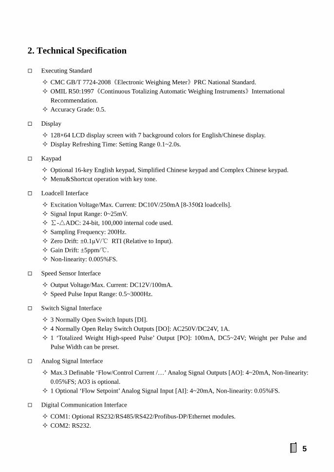
2. Technical Specification
Executing Standard
CMC GB/T 7724-2008《Electronic Weighing Meter》PRC National Standard. OMIL R50:1997《Continuous Totalizing Automatic Weighing Instruments》International
Recommendation. Accuracy Grade: 0.5.
Display
128×64 LCD display screen with 7 background colors for English/Chinese display. Display Refreshing Time: Setting Range 0.1~2.0s.
Kaypad
Optional 16-key English keypad, Simplified Chinese keypad and Complex Chinese keypad. Menu&Shortcut operation with key tone.
Loadcell Interface
Excitation Voltage/Max. Current: DC10V/250mA [8-350Ω loadcells]. Signal Input Range: 0~25mV. ∑-△ADC: 24-bit, 100,000 internal code used. Sampling Frequency: 200Hz. Zero Drift: ±0.1μV/℃ RTI (Relative to Input). Gain Drift: ±5ppm/℃. Non-linearity: 0.005%FS.
Speed Sensor Interface
Output Voltage/Max. Current: DC12V/100mA. Speed Pulse Input Range: 0.5~3000Hz.
Switch Signal Interface
3 Normally Open Switch Inputs [DI]. 4 Normally Open Relay Switch Outputs [DO]: AC250V/DC24V, 1A. 1 ‘Totalized Weight High-speed Pulse’ Output [PO]: 100mA, DC5~24V; Weight per Pulse and
Pulse Width can be preset.
Analog Signal Interface
Max.3 Definable ‘Flow/Control Current /…’ Analog Signal Outputs [AO]: 4~20mA, Non-linearity: 0.05%FS; AO3 is optional.
1 Optional ‘Flow Setpoint’ Analog Signal Input [AI]: 4~20mA, Non-linearity: 0.05%FS.
Digital Communication Interface
COM1: Optional RS232/RS485/RS422/Profibus-DP/Ethernet modules. COM2: RS232.

6
Connectable: IPC/PLC, LED Remote Display, Serial Printer and Wireless Module.
Report Print
Weight Records per shift/day/month of a year can be queried and printed.
Operating Specification
Operating Voltage: AC220V±15%, 50/60Hz. Max. Power Consumption: 15W. Outline Size Model Horizontal Panel-mounting: 164×86×193mm [W×H×D]. Model Vertical Panel-mounting: 86×164×193mm [W×H×D]. Model Wall-mounting: 202×305×90mm [W×H×D].
Panel Cut-out Size Model Horizontal Panel-mounting: 153×77mm [W×H]. Model Vertical Panel-mounting: 77×153mm [W×H].
Operating Temperature: -20℃ to +40℃. Storage Temperature: -30℃ to +60℃. Relative Humidity: Max. 85%RH. Protection Level Front Panel of Model Panel-mounting: IP65. Model Wall-mounting: IP65.
Weight Model Panel-mounting: Approx. 1.7kg. Model Wall-mounting: Approx. 3.4kg.
7
3. Operation Interface
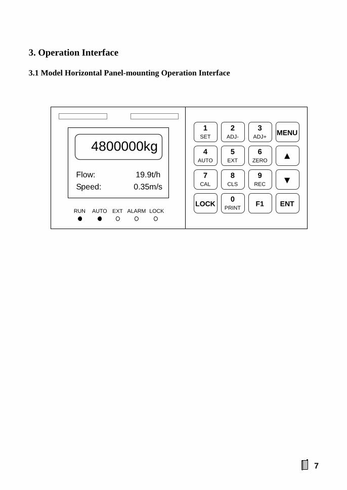
3.1 Model Horizontal Panel-mounting Operation Interface
Flow: 19.9t/h Speed: 0.35m/s
4800000kg
RUN AUTO EXT ALARM LOCK
1 SET
2 ADJ-
3 ADJ+ MENU
4 AUTO
5 EXT
6 ZERO ▲
7 CAL
8 CLS
9 REC ▼
LOCK 0 PRINT F1 ENT
8
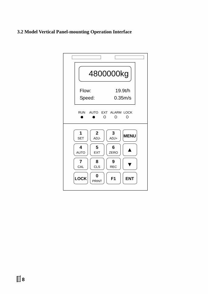
3.2 Model Vertical Panel-mounting Operation Interface
Flow: 19.9t/h Speed: 0.35m/s
4800000kg
RUN AUTO EXT ALARM LOCK
1 SET
2 ADJ-
3 ADJ+ MENU
4 AUTO
5 EXT
6 ZERO ▲
7 CAL
8 CLS
9 REC ▼
LOCK 0 PRINT F1 ENT
9
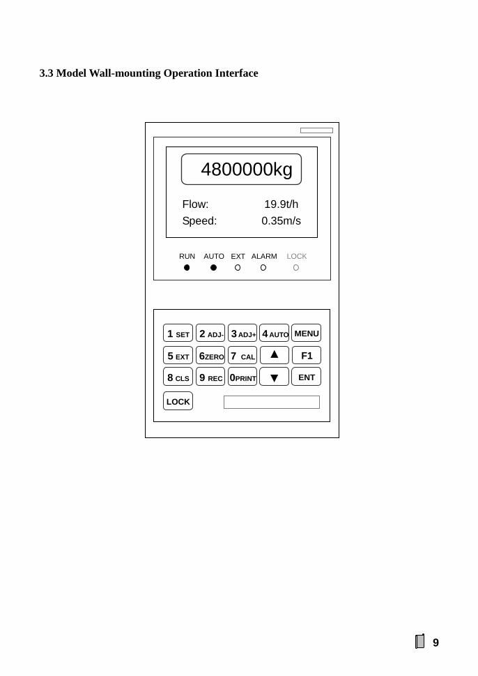
3.3 Model Wall-mounting Operation Interface
1 SET 2 ADJ- 3 ADJ+ 4 AUTO
LOCK
MENU
5 EXT 6ZERO 7 CAL ▲
F1
8 CLS 9 REC 0PRINT ▼ ENT
Flow: 19.9t/h Speed: 0.35m/s
4800000kg
RUN AUTO EXT ALARM LOCK
10
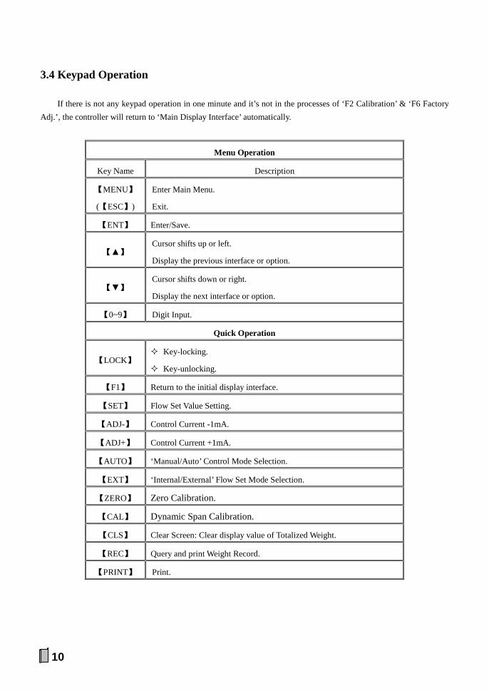
3.4 Keypad Operation
If there is not any keypad operation in one minute and it’s not in the processes of ‘F2 Calibration’ & ‘F6 Factory Adj.’, the controller will return to ‘Main Display Interface’ automatically.
Menu Operation
Key Name Description
【MENU】
(【ESC】)
Enter Main Menu.
Exit.
【ENT】 Enter/Save.
【▲】 Cursor shifts up or left.
Display the previous interface or option.
【▼】 Cursor shifts down or right.
Display the next interface or option.
【0~9】 Digit Input.
Quick Operation
【LOCK】 Key-locking.
Key-unlocking.
【F1】 Return to the initial display interface.
【SET】 Flow Set Value Setting.
【ADJ-】 Control Current -1mA.
【ADJ+】 Control Current +1mA.
【AUTO】 ‘Manual/Auto’ Control Mode Selection.
【EXT】 ‘Internal/External’ Flow Set Mode Selection.
【ZERO】 Zero Calibration.
【CAL】 Dynamic Span Calibration.
【CLS】 Clear Screen: Clear display value of Totalized Weight.
【REC】 Query and print Weight Record.
【PRINT】 Print.
11
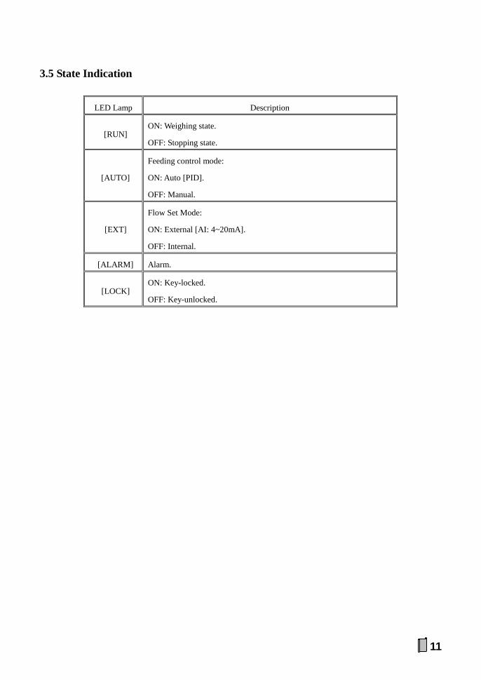
3.5 State Indication
LED Lamp Description
[RUN] ON: Weighing state.
OFF: Stopping state.
[AUTO]
Feeding control mode:
ON: Auto [PID].
OFF: Manual.
[EXT]
Flow Set Mode:
ON: External [AI: 4~20mA].
OFF: Internal.
[ALARM] Alarm.
[LOCK] ON: Key-locked.
OFF: Key-unlocked.

12
4. Installation&Connection
4.1 Installation
4.1.1 Model Panel-mounting Installation
Model Outline Size
W×H×D[mm]
Front Panel Size
W×H[mm]
Box Body Size
W1×H1[mm]
Panel Cut-out Size
W2×H2[mm]
Horizontal 164×86×193 164×86 152×76 153×77
Vertical 86×164×193 86×164 76×152 77×153
D
H
W
(H1)
(W1)
Outline Size Front Panel Size
W2
H2
Panel Cut-out Size Horizontal Installation Mode Vertical Installation Mode

13
4.1.2 Model Wall-mounting Installation
Outline Size
W×H×D[mm]
Mounting Size
W×H[mm]
Mounting Hole Size
[mm]
202×305×90 169×271 Ф9
Outline Size Installation Mode

14
4.2 Terminal
4.2.1 Model Horizontal Panel-mounting Terminal
4.2.2 Model Wall-mounting Terminal
AO/AI/PO
AO
1+
AO
1-
AO
2+
AO
2-
AO
3+
AO
3-
AI+
A
I- V
IN
PO
DO/DI
DO
1+
DO
1-
DO
2+
DO
2-
DO
3+
DO
3-
DO
4+
DO
4-
CO
M
DI1
D
I2
DI3
POWER
L E N
B- (
TXD
-) A
+(TX
D+)
D
P-(R
XD
+)
(RX
D-)
DP
+ G
ND
R
XD
TX
D
+5V
COM1 COM2 Optional Modules Fixed on PCB
1 9
LOADCELL
SENSOR
SIG
- S
IG+
EX
C-
EX
C+
SH
D
VS
- S
IN
VS
+
SE
N+
SE
N-
SPEED
1 10
SENSOR
VS
+ S
IN
VS
- S
HD
E
XC
+ E
XC
- S
IG+
SIG
-
SE
N-
SE
N+
AO/AI/PO
PO
V
IN
AI-
AI+
AO
3- A
O3+
AO
2- A
O2+
AO
1- A
O1+
DO/DI
DI3
DI2
DI1
CO
M
DO
4 - D
O4+
DO
3- D
O3+
DO
2- D
O2+
DO
1- D
O1+
COM1/2 POWER
N L E ETHERNET

15
4.2.3 Model Vertical Panel-mounting Terminal
PO VIN AI- AI+ AO3- AO3+ AO2- AO2+ AO1- AO1+
AO
/AI/P
O
DI3 DI2 DI1 COM DO4- DO4+ DO3- DO3+ DO2- DO2+ DO1- DO1+
DO
/DI
CO
M1/
2
N
L
E
POW
ER
ETH
ERN
ET
SEN
SOR
VS+ SIN VS- SHD EXC+ EXC- SIG+ SIG-
SEN- SEN+

16
No. Pin Description
SENSOR Loadcell / Speed Sensor Port
LOADCELL Loadcell
Connection Mode 6-Wire 4-Wire
[Default Set]
1 SEN+ Feedback Voltage +.
2 SEN- Feedback Voltage -.
3 SIG- Weighing Signal [mV]Input -. Weighing Signal [mV]Input -.
4 SIG+ Weighing Signal [mV]Input +. Weighing Signal [mV]Input +.
5 EXC- Excitation Voltage -. Excitation Voltage -.
6 EXC+ Excitation Voltage + [DC10V]. Excitation Voltage + [DC10V].
7 SHD Shield Ground. Shield Ground.
SPEED
Speed Sensor
3-Wire
[NPN Open-collector Output Type] 2-Wire Tachogenerator
8 VS- Voltage Output -. Pulse Signal Input -.
9 SIN Pulse Signal Input. Pulse Signal Input +. Sine Wave Signal Input
Terminal 1.
10 VS+ Voltage Output + [DC12V]. Sine Wave Signal Input
Terminal 2.
POWER AC220V[±15%] Power Input Port
1 N Null Wire.
2 E Protective Ground.
3 L Live Wire.
The metal shell should be grounded directly to avoid electric shock.

17
Digital Communication Port of Model Panel-mounting
No. Pin Description
COM1/2 COM1/COM2 Digital Communication Port
COM2 [DB9 Socket]
RS232 Digital Communication Port
1
2
3
4
5 GND Signal Ground / Shield Ground.
6 TXD Transmit Data.
7 RXD Receive Data.
8
9 +5V +5V/100mA Output.
COM1 RS232/RS485/RS422/Profibus-DP/Ethernet Digital Communication Port [It's optional to configure one of them]
DB9 Socket RS232 RS485 RS422 Profibus-DP
1 B- TXD-
2 RXD A+ TXD+
3 TXD RXD+ DP- [B-]
4 RXD-
5 GND
6
7
8 DP+ [A+]
9 +5V
RJ45[DCE] Socket Ethernet
[T568B Wiring Mode]
1 RXD+ Orange-white
2 RXD- Orange
3 TXD+ Green-white
4 Unused Blue
5 Unused Blue-white
6 TXD- Green
7 Unused Brown-white
8 Unused Brown
18
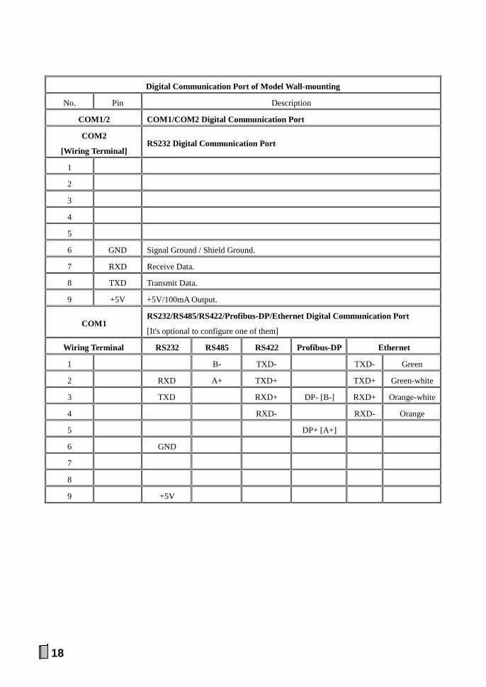
Digital Communication Port of Model Wall-mounting
No. Pin Description
COM1/2 COM1/COM2 Digital Communication Port
COM2
[Wiring Terminal] RS232 Digital Communication Port
1
2
3
4
5
6 GND Signal Ground / Shield Ground.
7 RXD Receive Data.
8 TXD Transmit Data.
9 +5V +5V/100mA Output.
COM1 RS232/RS485/RS422/Profibus-DP/Ethernet Digital Communication Port
[It's optional to configure one of them]
Wiring Terminal RS232 RS485 RS422 Profibus-DP Ethernet
1 B- TXD- TXD- Green
2 RXD A+ TXD+ TXD+ Green-white
3 TXD RXD+ DP- [B-] RXD+ Orange-white
4 RXD- RXD- Orange
5 DP+ [A+]
6 GND
7
8
9 +5V

19
No. Pin Description
AO/AI/PO Analog Output / Analog Input / High-speed Pulse Output Port
AO Analog Output Port [Definable]
1 AO1+ 4~20mA Output 1 [+/-].
2 AO1-
3 AO2+ 4~20mA Output 2 [+/-].
4 AO2-
5 AO3+ 4~20mA Output 3 [+/-].
[It's optional to configure it]. 6 AO3-
AI Analog Input Port
7 AI+ 4~20mA Input +.
8 AI- 4~20mA Input -.
PO Totalized Weight High-speed Pulse Output Port
9 VIN DC5~24V Input.
10 PO Totalized Weight High-speed Pulse Output.
No. Pin Description
DO/DI Relay Switch Signal Output / Switch Signal Input Port
DO Relay Switch Signal Output [Definable]
1 DO1+ Normally Open Contact Output 1 [+/-].
2 DO1-
3 DO2+ Normally Open Contact Output 2 [+/-].
4 DO2-
5 DO3+ Normally Open Contact Output 3 [+/-].
6 DO3-
7 DO4+ Normally Open Contact Output 4 [+/-].
8 DO4-
DI Switch Signal Input [Definable]
9 COM DI Common Terminal [GND].
10 DI1 Switch Signal Input 1.
11 DI2 Switch Signal Input 2.
12 DI3 Switch Signal Input 3.
Contact Capacity of Relay Switch: AC250V/DC24V, 1A.
20
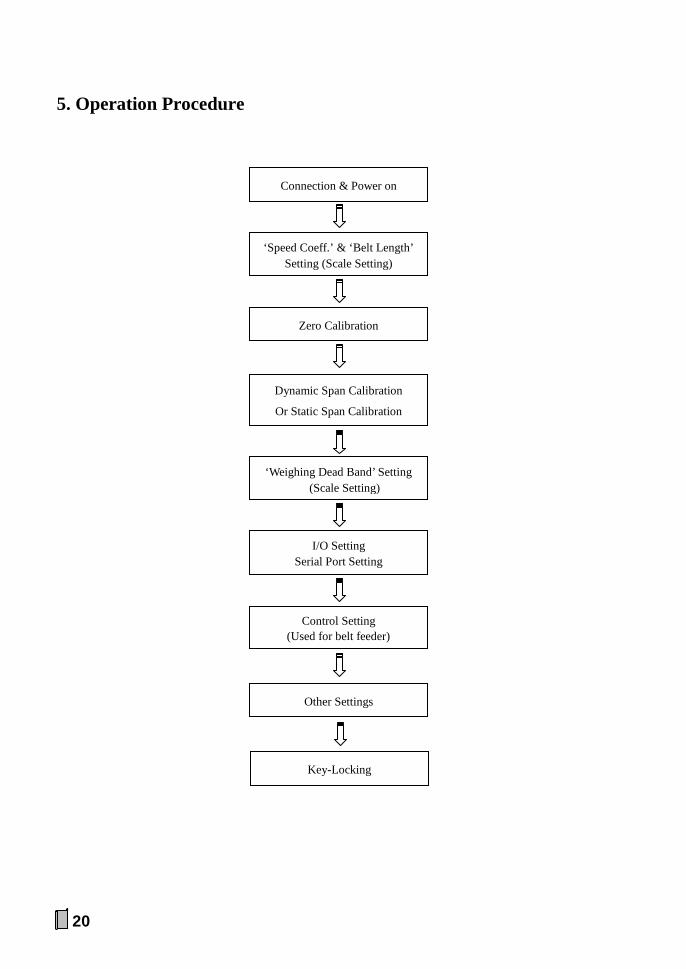
5. Operation Procedure
Connection & Power on
Zero Calibration
I/O Setting Serial Port Setting
Control Setting (Used for belt feeder)
Other Settings
‘Weighing Dead Band’ Setting (Scale Setting)
Key-Locking
‘Speed Coeff.’ & ‘Belt Length’ Setting (Scale Setting)
Dynamic Span Calibration
Or Static Span Calibration

21
6. Function&Operation
The following display&operation interfaces are described with ‘kg’ as the Internal Scale Unit. If the parameter ‘[P107] Internal Scale Unit’ is set to ‘g’, the actual Weight Display Unit will be different.
6.1 Main Display Interface
【▼】【▲】: Display the next/previous interface.
6.1.1 Totalized Weight, Flow & Belt Speed
Press【PRINT】key to print: 2009-05-20 23:59
4800000kg
6.1.2 Totalized Weight, Flow & Flow Setpoint
0020.00 [t/h]
R: 0.00-5000.00
P200 Flow Set
Flow[↑↓]: 19.9t/h Set: 20.0t/h
4800000kg
【ENT】: Set ‘Flow Setpoint’ value
↑: Upper Limit ↓: Lower Limit
Flow[↑↓]: 19.9t/h Speed[↑↓]: 0.35m/s
4800000kg

22
6.1.3 Totalized Weight, Flow & Control Current
6.1.4 Totalized Weight, Load & Load Setpoint
Load=Flow / (3.6×Speed) Load Setpoint=Flow Setpoint / (3.6×Speed) Load: kg/m Flow: t/h Belt Speed: m/s
Load[↑↓]: 15.8kg/m Set: 15.9kg/m
4800000kg
12.26 [mA]
R: 4.00-20.00
Control Current
Flow[↑↓]: 19.9t/h Ctrl[↑↓]: 12.26mA
4800000kg
【ENT】: Set ‘Control Current’ value
【ADJ-】【ADJ+】: Control Current ±1mA

23
6.1.5 Totalized Weight, Date & Time
6.1.6 Totalized Weight, Batch Weight & Batch Weight Setpoint
2009-05-20 23:59:45 Wed.
4800000kg
Month-Day-Year Hour: Minute: Second Week
Batch[↑]: 0kg Set: 0kg
4800000kg
00000000 [kg]
R: 0-99999999
P217 Batch Set
【ENT】: Set ‘Batch Weight Setpoint’ value
↑: BatchEnd (Totalized Weight reaches to Batch Weight Setpoint)

24
6.1.7 Alarm Items
Alarm Item Alarm Condition
Flow Upper Limit Flow ≥ Flow Range × Flow Upper Limit(%)
Flow Lower Limit Flow ≤ Flow Range × Flow Lower Limit(%)
Load Upper Limit Load ≥ Load Range × Load Upper Limit(%)
Load Lower Limit Load ≤ Load Range × Load Lower Limit(%)
Speed Upper Limit Speed ≥ Speed Range × Speed Upper Limit(%)
Speed Lower Limit Speed ≤ Speed Range × Speed Lower Limit(%)
Control Current Upper Limit Control Current ≥ PID Control Current Upper Limit
Control Current Lower Limit Control Current ≥ PID Control Current Lower Limit
Flow Positive Deviation Limit Flow Deviation [E%] > Flow Positive Deviation Limit
Flow Negative Deviation Limit Flow Deviation [E%] < Flow Negative Deviation Limit
Flow Deviation Value [E%]
XXX.X%
Flow Deviation [E%] = ((Flow -Flow Setpoint) / Flow
Setpoint) × 100%
OK: Normal
HI: Upper Limit / Positive Deviation Limit
LO: Lower Limit / Negative Deviation Limit
Flow:OK Load:OK
Speed:OK Ctrl: OK Dev:OK -0.5%
Alarm Items

25
6.1.8 DI&DO
DI: Switch Input; DO: Switch Output
6.1.9 AI&AO
AI: Analog Input (4.00~20.00mA) AO: Analog Output (4.00~20.00mA)
6.1.10 AD Value, Totalized Weight Pulse, Total Weight of Present Shift
LP-Totalized Weight Low-speed Pulse HP-Totalized Weight High-speed Pulse Total-Totalized Weight of Present Shift
DI3: OFF DO1:OFF DO2:OFF DO3:OFF DO4:OFF
DI1: OFF DI2:OFF
AO1: 4.00mA AO2: 4.00mA AO3: 4.00mA
AI: 4.00mA
LP: 4800
HP: 48000
Total: 190150kg
AD: 25122
26
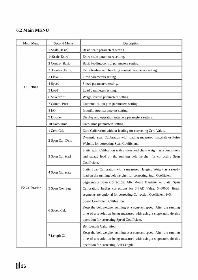
6.2 Main MENU
Main Menu Second Menu Description
F1 Setting
1 Scale[Basic] Basic scale parameters setting.
1+Scale[Extra] Extra scale parameters setting.
2 Control[Basic] Basic feeding control parameters setting.
2+Control[Extra] Extra feeding and batching control parameters setting.
3 Flow Flow parameters setting.
4 Speed Speed parameters setting.
5 Load Load parameters setting.
6 Save/Print Weight record parameters setting.
7 Comm. Port Communication port parameters setting.
8 I/O Input&output parameters setting.
9 Display Display and operation interface parameters setting.
10 Date/Time Date/Time parameters setting.
F2 Calibration
1 Zero Cal. Zero Calibration without loading for correcting Zero Value.
2 Span Cal. Dyn. Dynamic Span Calibration with loading measured materials or Poise
Weights for correcting Span Coefficient.
3 Span Cal.Stat1
Static Span Calibration with a measured chain weight as a continuous
and steady load on the running belt weigher for correcting Span
Coefficient.
4 Span Cal.Stat2 Static Span Calibration with a measured Hanging Weight as a steady
load on the running belt weigher for correcting Span Coefficient.
5 Span Cor. Seg.
Segmenting Span Correction. After doing Dynamic or Static Span
Calibration, further corrections for 3 [AD Value: 0~60000] linear
segments are optional for correcting Correction Coefficient 1~3.
6 Speed Cal.
Speed Coefficient Calibration.
Keep the belt weigher running at a constant speed. After the running
time of a revolution being measured with using a stopwatch, do this
operation for correcting Speed Coefficient.
7 Length Cal.
Belt Length Calibration.
Keep the belt weigher running at a constant speed. After the running
time of a revolution being measured with using a stopwatch, do this
operation for correcting Belt Length.

27
Main Menu Second Menu Description
F3 Weight Record Query and print Weight Records.
F4 Data Clearing
1 Clear Screen
Clear Totalized Weight and Totalized Weight Pulse Count.
But Totalized Weight of Current Shift will not be cleared, so this
operation has no effect on recording of weight per shift.
2 Clear Weight
Clear Totalized Weight, Totalized Weight Pulse Count and Totalized
Weight of Current Shift.
The cleared value of Totalized Weight of Current Shift will not be
recorded.
3 Clear Records
Clear History Records of Totalized Weight.
But Current Totalized Weight, Totalized Weight Pulse Count and
Totalized Weight of Current Shift will not be cleared.
F5 Security
1 Auto-locking
If there is not any keypad operation in one minute and it’s not in the
processes of ‘F2 Calibration’ & ‘F6 Factory Adj.’, the controller will
lock the keypad and return to ‘Main Display Interface’ automatically.
2 Key-locking Locking keypad.
3 Key-unlocking Unlocking keypad.
4 Password Set Exfactory Password: 000001.
5 RAM Reset Restore to factory defaults.
F6 Factory Adj. Special for manufacturer.
F7 Product Info.
Only for query.
1 Version No. Version No.
2 Serial No. Serial No.
3 Exfactory Date Exfactory Date.
4 Audit Counter Audit Trail Counter [0~99999999] for Scale parameter’s
modification.
5 Auth. Code Authorization Code.

28
6.3 F1 Setting
6.3.1 Basic Scale Parameters
No. Parameter Range Default Set
P100 DispalyUnit
(Weight Display Unit)
0: kg
1: t
([P107] Scale Unit = kg) 0
0: g
1: kg
([P107] Scale Unit = g)
P101 Decimal
(Weight Decimal Point)
0: o
1: o.o
2: o.oo
When [P100]=1, it’s valid.
1
P102 Belt Length 0.01~5000.00m 10.00
[*]
P103 SpeedCoeff.
(Speed Coefficient) 1.0~99999.9pl/m (pulse/m)
100.0
[*]
P104 Zero Value 0~60000 (AD Value) 15000
[*]
P105 Span Coeff.
(Span Coefficient) 1~99999999
200000
[*]
P106 SL Deadband
(Weighing Daedband)
±(0.00~200.00) t/h
([P107] Scale Unit = kg)
If Flow < Deadband value, the variance of
Totalized Weight will be ignored. ±0.00
±(0.00~200.00) kg/h
([P107] Scale Unit = g)
P107 Scale Unit
(Internal Scale Unit)
0: kg
1: g
0/1
[*]
[*]: ‘RAM Reset’ operation has no effect on this parameter.

29
6.3.2 Extra Scale Parameters
No. Parameter Range Default Set
P110 Cal. Revs (Calibration Revolutions)
1~99R (1R=1 Belt Length) 3
P111 ChainWeight
0.1~1000.0kg/m ([P107] Scale Unit = kg) Chain Weight for Span Calibration 10.0 0.1~1000.0g/m ([P107] Scale Unit = g)
P112 HangWeight
0.1~1000.0kg ([P107] Scale Unit = kg) Hanging Weight for Span Calibration 10.0 0.1~1000.0g ([P107] Scale Unit = g)
P113 WeighLength 0.001~50.000m 1.000
P114 Cal.Current 4.00~20.00mA Control Current for System Calibration
12.00
P115 Zero Track (Zero Tracking Permission)
0: OFF; 1: ON 0
P116 Track Range (Zero Tracking Range)
±(0~10%) × [P302] Flow Range ±5%
P117 Zero Adjust (Zero Adjusting Range)
±(0~10%) × [P104] Zero Value ±5%
P118 ZeroRefresh 0: RAM (Only Refresh RAM Zero Value) 1: FLASH/RAM (Refresh Original Zero Value)
0
P119 Breakpoint1 0~[P120] (AD Value: 0~60000) Breakpoint1 of Segmenting Span Correction
18000
P120 Breakpoint2 [P119]~Max. AD Value (60000) Breakpoint2 of Segmenting Span Correction
42000
P121 Cor. Coeff1 0.500~2.000; Span Correction Coefficient of AD Value Linear Segment 1: 0~[P119]
1.000
P122 Cor. Coeff2 0.500~2.000; Span Correction Coefficient of AD Value Linear Segment 2: [P119]~[P120]
1.000
P123 Cor. Coeff3 0.500~2.000; Span Correction Coefficient of AD Value Linear Segment 3: [P120~Max. AD Value
1.000
P124 Cal. Add (Totalizing While Calibrating)
0: OFF 1: ON [In the process of ‘Load Calibration’, the inputted actual weight value will be added to Totalized Weight]
0
P125 Neg. Add (Negative Totalizing)
0: OFF [The negative variance of Totalized Weight will be ignored] 1: ON
1
30
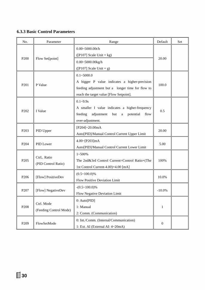
6.3.3 Basic Control Parameters
No. Parameter Range Default Set
P200 Flow Set[point]
0.00~5000.00t/h
([P107] Scale Unit = kg) 20.00
0.00~5000.00kg/h
([P107] Scale Unit = g)
P201 P Value
0.1~5000.0
A bigger P value indicates a higher-precision
feeding adjustment but a longer time for flow to
reach the target value [Flow Setpoint].
100.0
P202 I Value
0.1~9.9s
A smaller I value indicates a higher-frequency
feeding adjustment but a potential flow
over-adjustment.
0.5
P203 PID Upper [P204]~20.00mA
Auto[PID]/Manual Control Current Upper Limit 20.00
P204 PID Lower 4.00~[P203]mA
Auto[PID]/Manual Control Current Lower Limit 5.00
P205 CtrL. Ratio
(PID Control Ratio)
1~500%
The 2nd&3rd Control Current=Control Ratio×(The
1st Control Current-4.00)+4.00 [mA]
100%
P206 [Flow] PositiveDev (0.5~100.0)%
Flow Positive Deviation Limit 10.0%
P207 [Flow] NegativeDev -(0.5~100.0)%
Flow Negative Deviation Limit -10.0%
P208 Ctrl. Mode
(Feeding Control Mode)
0: Auto[PID]
1: Manual
2: Comm. (Communication)
1
P209 FlowSetMode 0: Int./Comm. (Internal/Communication)
1: Ext. AI (External AI: 4~20mA) 0

31
6.3.4 Extra Control Parameters
No. Parameter Range Default Set
P210 InIHoldTime 0.0-999.9s PID Initial Current Hold Time
2.0
P211 PID Ini.Cur (PID Initial Current)
0: Present (Present Current Value) 1: Fuzzy (Fuzzy Current Value) 2: Set [P219] (Set Value of [P219])
0
P212 Fuzzy Equ. (Fuzzy Equivalent)
0.01~100.00 [t/h]/mA ([P107] Scale Unit = kg) Flow Increment per Increasing 1mA Adjusting Current.
2.50
0.01~100.00 [kg/h]/mA ([P107] Scale Unit = g)
P213 ST/SP Delay (Start/Stop Delay Time)
0.0~999.9s Delay Time of Feeder Starting Delay Time of Scale Stopping
0.0
P214 BatchPermit (Batch Permission)
0: OFF; 1: ON 0
P215 Batch Loop (Batch Loop Mode)
0: Manual Mode; 1: Auto Mode 0
P216 Batch Int. (Batch Interval)
0.0~9999.9s 60.0
P217 Batch Set (Batch Weight Setpoint)
0~99999999kg ([P107] Scale Unit = kg)
0 0~99999999g ([P107] Scale Unit = g)
P218 BatchPreact
0~[P217] kg ([P107] Scale Unit = kg) Batch Preact Weight 0 0~[P217] g ([P107] Scale Unit = g)
P219 Set Current 4.00~20.00mA Set Value of PID Initial Current
12.00
Note:
[P213] Start/Stop Delay: 1. Delay Time of Feeder Starting: When there is a “DI.Start” pulse signal input, ‘DO. Scale Start&Stop Control’ will turn on to start the belt weigher, and after delaying this time, ‘DO. Feeder Start&Stop Control’ will turn on to start the feeder.
2. Delay Time of Scale Stopping: When there is a “DI.Stop” pulse signal input, ‘DO. Feeder Start&Stop Control’ will turn off to stop the feeder, and after delaying this time, ‘DO. Scale Start&Stop Control’ will turn off to stop the belt weigher.

32
6.3.5 Flow Parameters
No. Parameter Range Default Set
P300 DisplayUnit
(Flow Display Unit)
0: t/h
1: kg/min
2: kg/h
([P107] Scale Unit = kg) 0
0: kg/h
1: g/min
2: g/h
([P107] Scale Unit = g)
P301 Decimal
(Flow Decimal Point)
0: o
1: o.o
2: o.oo
1
P302 Flow Range
0.01~5000.00t/h
([P107] Scale Unit = kg) 100.00
0.01~5000.00kg/h
([P107] Scale Unit = g)
P303 Flow Upper
(Flow Upper Limit) (0.0~100.0)% Flow Range 100.0%
P304 Flow Lower
(Flow Lower Limit) (0.0~100.0)% Flow Range 0.0%
P305 Flow Filter 1~200 10
P306 FlowFilter2 1~100
The secondary filter for flow display. 1
P307 Filter2 Dev
±(0~20)%
Flow Deviation Range for Flow Filter2
When Flow Deviation [E%] is within this range, the
secondary filter will work.
±2%

33
6.3.6 Speed Parameters
No. Parameter Range Default Set
P400 Decimal
(Speed Decimal Point)
0: o
1: o.o
2: o.oo
3: o.ooo
2
P401 Speed Range 0.100~5.000m/s 3.000
P402 Speed Upper
(Speed Upper Limit) (0.0~100.0)% Speed Range 100.0%
P403 Speed Lower
(Speed Lower Limit) (0.0~100.0)% Speed Range 0.0%
P404 SpeedFilter 1~200 10
P405 SpeedSource
0: Ext. Speed (Weighing by the external speed)
1: Int. Speed1 (Weighing by the internal speed)
2: Int. Speed2 (Connect a normally open switch
related to the running state of the weighing belt
between the terminals ‘SIN’ and ‘VS-’. Switch ON
with Belt’s Running: Weighing by the internal speed;
Switch OFF with Belt’s Stopping: Stop weighing)
3: Int. Speed3 (Weighing by the internal speed while
the external speed pulse inputting)
Note: If a DI signal is defined as ‘1: Weighing’, then
only when this DI turns on, the weighing process is
allowed.
0
P406 Int. Speed
(Internal Speed) 0.001~5.000m/s 0.500
P407 Pulse Upper
0.1~3.0kHz
Speed Pulse Frequency Upper Limit: if the frequency
of speed pulse exceeds this set value, the speed pulse
will be invalid.
1.0
34
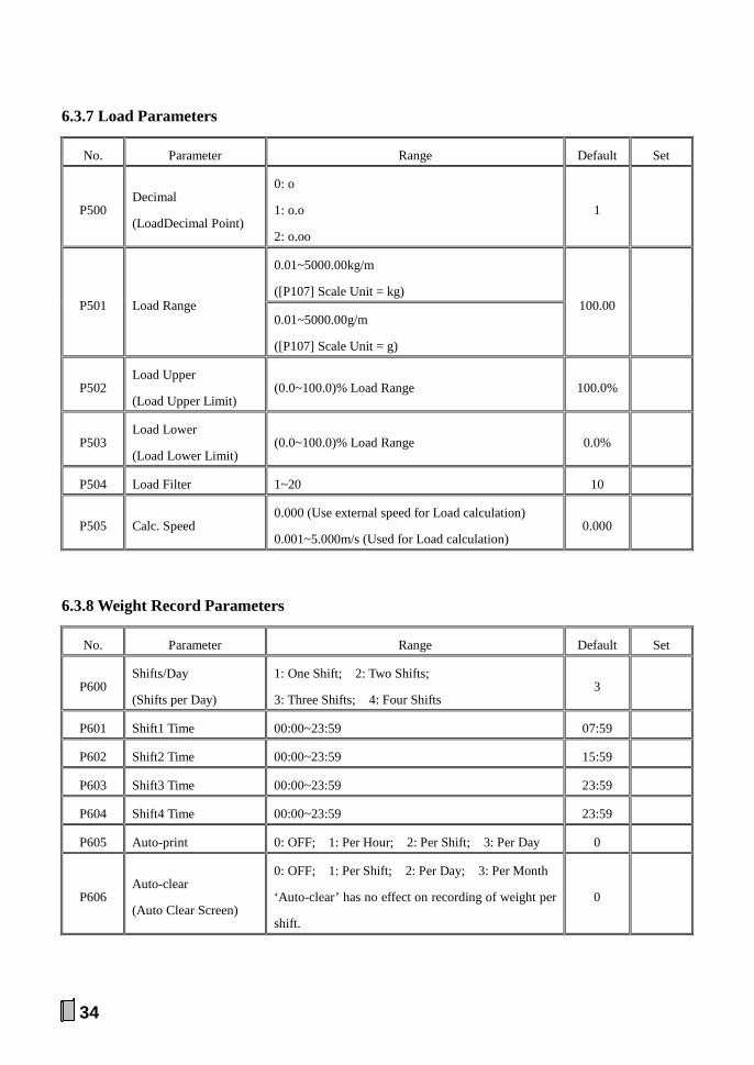
6.3.7 Load Parameters
No. Parameter Range Default Set
P500 Decimal
(LoadDecimal Point)
0: o
1: o.o
2: o.oo
1
P501 Load Range
0.01~5000.00kg/m
([P107] Scale Unit = kg) 100.00
0.01~5000.00g/m
([P107] Scale Unit = g)
P502 Load Upper
(Load Upper Limit) (0.0~100.0)% Load Range 100.0%
P503 Load Lower
(Load Lower Limit) (0.0~100.0)% Load Range 0.0%
P504 Load Filter 1~20 10
P505 Calc. Speed 0.000 (Use external speed for Load calculation)
0.001~5.000m/s (Used for Load calculation) 0.000
6.3.8 Weight Record Parameters
No. Parameter Range Default Set
P600 Shifts/Day
(Shifts per Day)
1: One Shift; 2: Two Shifts;
3: Three Shifts; 4: Four Shifts 3
P601 Shift1 Time 00:00~23:59 07:59
P602 Shift2 Time 00:00~23:59 15:59
P603 Shift3 Time 00:00~23:59 23:59
P604 Shift4 Time 00:00~23:59 23:59
P605 Auto-print 0: OFF; 1: Per Hour; 2: Per Shift; 3: Per Day 0
P606 Auto-clear
(Auto Clear Screen)
0: OFF; 1: Per Shift; 2: Per Day; 3: Per Month
‘Auto-clear’ has no effect on recording of weight per
shift.
0
35
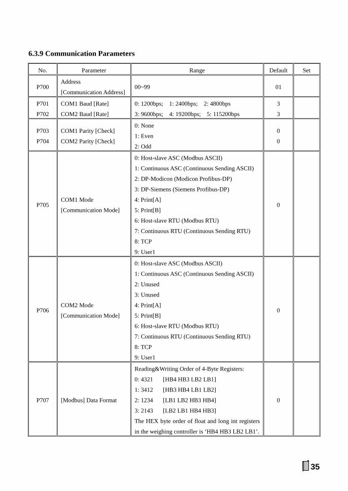
6.3.9 Communication Parameters
No. Parameter Range Default Set
P700 Address
[Communication Address] 00~99 01
P701
P702
COM1 Baud [Rate]
COM2 Baud [Rate]
0: 1200bps; 1: 2400bps; 2: 4800bps
3: 9600bps; 4: 19200bps; 5: 115200bps
3
3
P703
P704
COM1 Parity [Check]
COM2 Parity [Check]
0: None
1: Even
2: Odd
0
0
P705 COM1 Mode
[Communication Mode]
0: Host-slave ASC (Modbus ASCII)
1: Continuous ASC (Continuous Sending ASCII)
2: DP-Modicon (Modicon Profibus-DP)
3: DP-Siemens (Siemens Profibus-DP)
4: Print[A]
5: Print[B]
6: Host-slave RTU (Modbus RTU)
7: Continuous RTU (Continuous Sending RTU)
8: TCP
9: User1
0
P706 COM2 Mode
[Communication Mode]
0: Host-slave ASC (Modbus ASCII)
1: Continuous ASC (Continuous Sending ASCII)
2: Unused
3: Unused
4: Print[A]
5: Print[B]
6: Host-slave RTU (Modbus RTU)
7: Continuous RTU (Continuous Sending RTU)
8: TCP
9: User1
0
P707 [Modbus] Data Format
Reading&Writing Order of 4-Byte Registers:
0: 4321 [HB4 HB3 LB2 LB1]
1: 3412 [HB3 HB4 LB1 LB2]
2: 1234 [LB1 LB2 HB3 HB4]
3: 2143 [LB2 LB1 HB4 HB3]
The HEX byte order of float and long int registers
in the weighing controller is ‘HB4 HB3 LB2 LB1’.
0
36
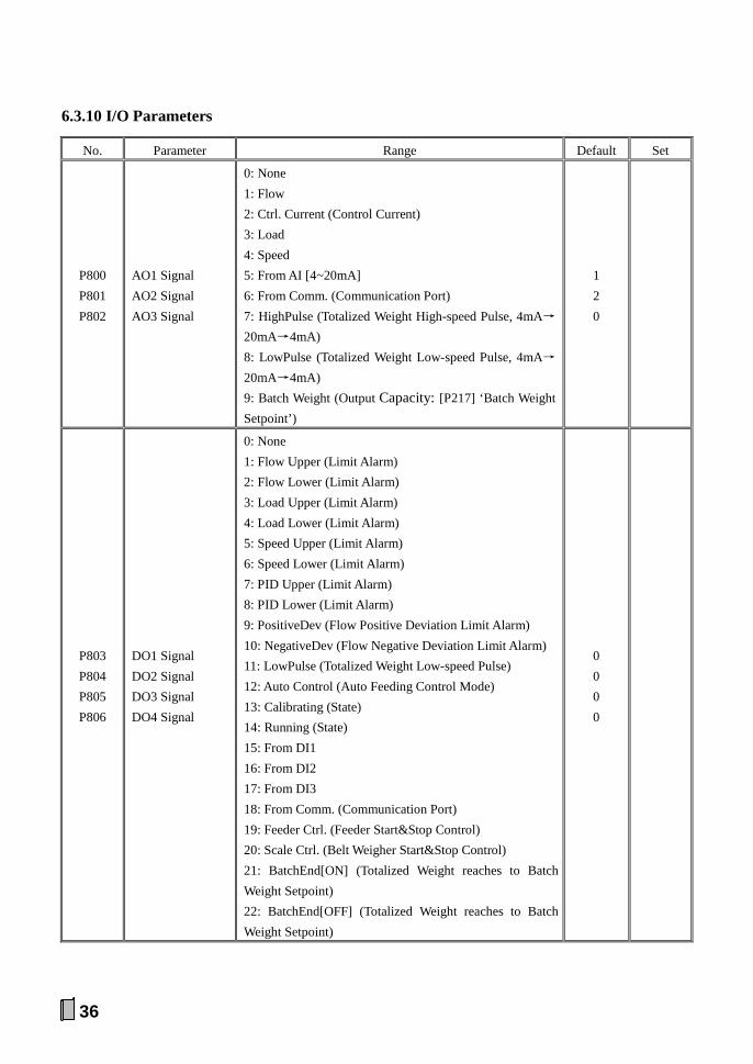
6.3.10 I/O Parameters
No. Parameter Range Default Set
P800 P801 P802
AO1 Signal AO2 Signal AO3 Signal
0: None 1: Flow 2: Ctrl. Current (Control Current) 3: Load 4: Speed 5: From AI [4~20mA] 6: From Comm. (Communication Port) 7: HighPulse (Totalized Weight High-speed Pulse, 4mA→
20mA→4mA) 8: LowPulse (Totalized Weight Low-speed Pulse, 4mA→
20mA→4mA) 9: Batch Weight (Output Capacity: [P217] ‘Batch Weight Setpoint’)
1 2 0
P803 P804 P805 P806
DO1 Signal DO2 Signal DO3 Signal DO4 Signal
0: None 1: Flow Upper (Limit Alarm) 2: Flow Lower (Limit Alarm) 3: Load Upper (Limit Alarm) 4: Load Lower (Limit Alarm) 5: Speed Upper (Limit Alarm) 6: Speed Lower (Limit Alarm) 7: PID Upper (Limit Alarm) 8: PID Lower (Limit Alarm) 9: PositiveDev (Flow Positive Deviation Limit Alarm) 10: NegativeDev (Flow Negative Deviation Limit Alarm) 11: LowPulse (Totalized Weight Low-speed Pulse) 12: Auto Control (Auto Feeding Control Mode) 13: Calibrating (State) 14: Running (State) 15: From DI1 16: From DI2 17: From DI3 18: From Comm. (Communication Port) 19: Feeder Ctrl. (Feeder Start&Stop Control) 20: Scale Ctrl. (Belt Weigher Start&Stop Control) 21: BatchEnd[ON] (Totalized Weight reaches to Batch Weight Setpoint) 22: BatchEnd[OFF] (Totalized Weight reaches to Batch Weight Setpoint)
0 0 0 0
37
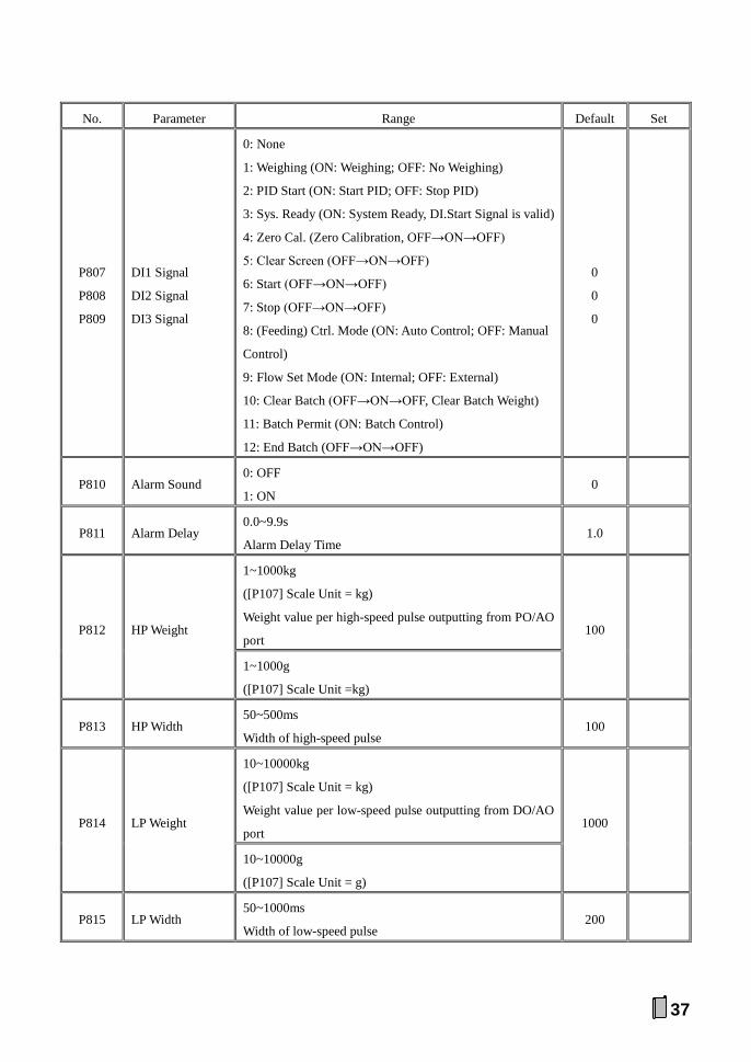
No. Parameter Range Default Set
P807
P808
P809
DI1 Signal
DI2 Signal
DI3 Signal
0: None
1: Weighing (ON: Weighing; OFF: No Weighing)
2: PID Start (ON: Start PID; OFF: Stop PID)
3: Sys. Ready (ON: System Ready, DI.Start Signal is valid)
4: Zero Cal. (Zero Calibration, OFF→ON→OFF)
5: Clear Screen (OFF→ON→OFF)
6: Start (OFF→ON→OFF)
7: Stop (OFF→ON→OFF)
8: (Feeding) Ctrl. Mode (ON: Auto Control; OFF: Manual
Control)
9: Flow Set Mode (ON: Internal; OFF: External)
10: Clear Batch (OFF→ON→OFF, Clear Batch Weight)
11: Batch Permit (ON: Batch Control)
12: End Batch (OFF→ON→OFF)
0
0
0
P810 Alarm Sound 0: OFF
1: ON 0
P811 Alarm Delay 0.0~9.9s
Alarm Delay Time 1.0
P812 HP Weight
1~1000kg
([P107] Scale Unit = kg)
Weight value per high-speed pulse outputting from PO/AO
port 100
1~1000g
([P107] Scale Unit =kg)
P813 HP Width 50~500ms
Width of high-speed pulse 100
P814 LP Weight
10~10000kg
([P107] Scale Unit = kg)
Weight value per low-speed pulse outputting from DO/AO
port 1000
10~10000g
([P107] Scale Unit = g)
P815 LP Width 50~1000ms
Width of low-speed pulse 200
38
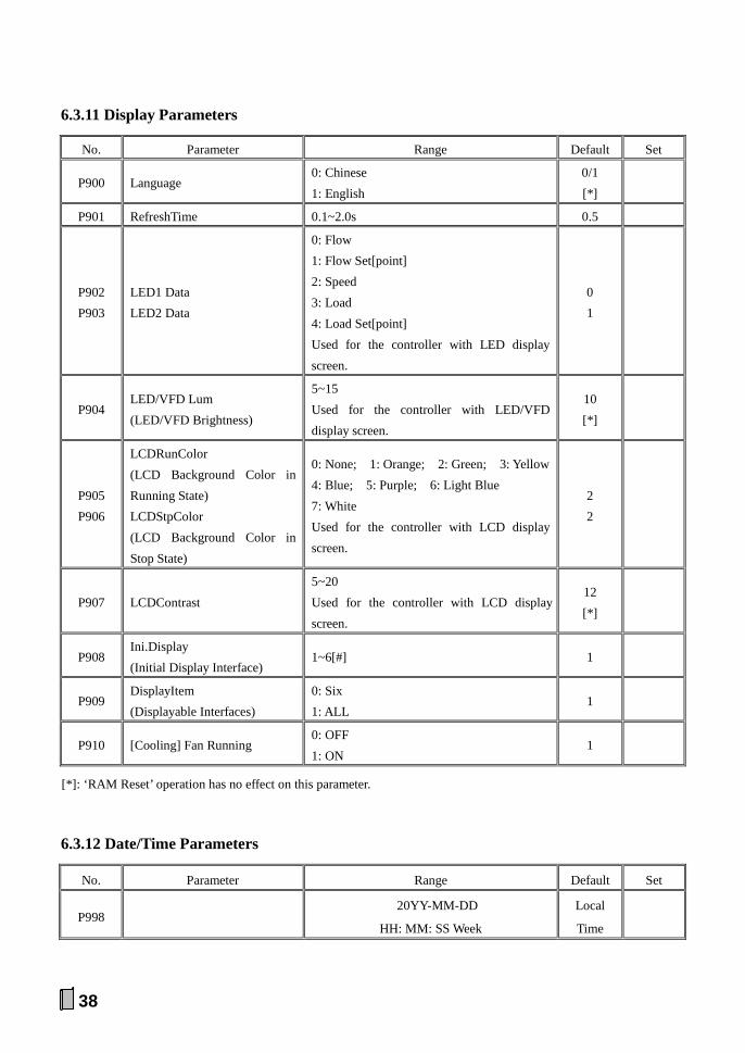
6.3.11 Display Parameters
No. Parameter Range Default Set
P900 Language 0: Chinese 1: English
0/1 [*]
P901 RefreshTime 0.1~2.0s 0.5
P902 P903
LED1 Data LED2 Data
0: Flow 1: Flow Set[point] 2: Speed 3: Load 4: Load Set[point] Used for the controller with LED display screen.
0 1
P904 LED/VFD Lum (LED/VFD Brightness)
5~15 Used for the controller with LED/VFD display screen.
10 [*]
P905 P906
LCDRunColor (LCD Background Color in Running State) LCDStpColor (LCD Background Color in Stop State)
0: None; 1: Orange; 2: Green; 3: Yellow 4: Blue; 5: Purple; 6: Light Blue 7: White Used for the controller with LCD display screen.
2 2
P907 LCDContrast 5~20 Used for the controller with LCD display screen.
12 [*]
P908 Ini.Display (Initial Display Interface)
1~6[#] 1
P909 DisplayItem (Displayable Interfaces)
0: Six 1: ALL
1
P910 [Cooling] Fan Running 0: OFF 1: ON
1
[*]: ‘RAM Reset’ operation has no effect on this parameter.
6.3.12 Date/Time Parameters
No. Parameter Range Default Set
P998 20YY-MM-DD
HH: MM: SS Week
Local
Time

39
6.3.13 A Sample of Parameter Setting
Modify the parameter ‘[P103] Speed Coefficient’.
【▲】【▼】: Moving cursor. 【0~9】: Digit input.
Main Display Interface
【MENU】+【▲】【▼】: F1 Setting 【ENT】
【ENT】+【▲】【▼】
【ENT】
1+Scale[Extra] 2 Control[Basic]
F1Setting 1 Scale[Basic]
P102 Belt Length
P103 SpeedCoeff.
1 Scale[Basic] P101 Decimal
【MENU】: Exit 【ENT】: Save
M
0100.00
R: 1.0-99999.9
P103 SpeedCoeff.
M
40
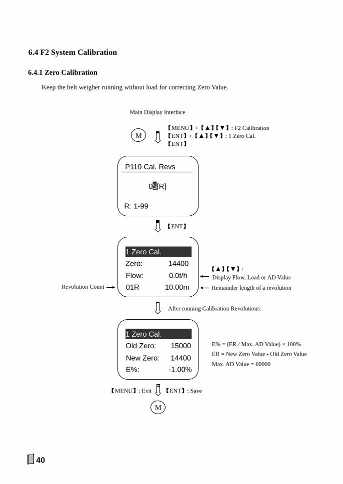
6.4 F2 System Calibration
6.4.1 Zero Calibration
Keep the belt weigher running without load for correcting Zero Value.
【MENU】: Exit 【ENT】: Save
M
New Zero: 14400 E%: -1.00%
1 Zero Cal. Old Zero: 15000
05[R]
R: 1-99
P110 Cal. Revs
Remainder length of a revolution
【▲】【▼】: Display Flow, Load or AD Value
Main Display Interface
【MENU】+【▲】【▼】: F2 Calibration 【ENT】+【▲】【▼】: 1 Zero Cal. 【ENT】
M
【ENT】
Flow: 0.0t/h 01R 10.00m
1 Zero Cal. Zero: 14400
Revolution Count
After running Calibration Revolutions:
E% = (ER / Max. AD Value) × 100% ER = New Zero Value - Old Zero Value
Max. AD Value = 60000
41
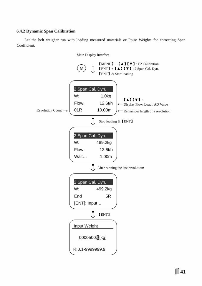
6.4.2 Dynamic Span Calibration
Let the belt weigher run with loading measured materials or Poise Weights for correcting Span Coefficient.
After running the last revolution:
End 5R
[ENT]: Input…
2 Span Cal. Dyn. W: 499.2kg
【ENT】
Flow: 12.6t/h
Wait… 1.00m
2 Span Cal. Dyn. W: 489.2kg
Main Display Interface
【MENU】+【▲】【▼】: F2 Calibration 【ENT】+【▲】【▼】: 2 Span Cal. Dyn. 【ENT】& Start loading
M
Remainder length of a revolution
Flow: 12.6t/h 01R 10.00m
2 Span Cal. Dyn. W: 1.0kg
Revolution Count
【▲】【▼】: Display Flow, Load , AD Value
Stop loading &【ENT】
0000500.0[kg]
R:0.1-9999999.9
Input Weight
42
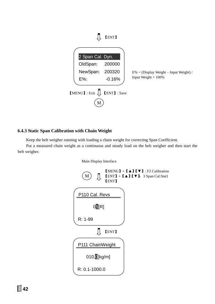
6.4.3 Static Span Calibration with Chain Weight
Keep the belt weigher running with loading a chain weight for correcting Span Coefficient. Put a measured chain weight as a continuous and steady load on the belt weigher and then start the
belt weigher.
05[R]
R: 1-99
P110 Cal. Revs
Main Display Interface
【MENU】+【▲】【▼】: F2 Calibration 【ENT】+【▲】【▼】:3 Span Cal.Stat1 【ENT】
M
【ENT】
R: 0.1-1000.0
P111 ChainWeight
010.0[kg/m]
【MENU】: Exit 【ENT】: Save
【ENT】
M
NewSpan: 200320
E%: -0.16%
2 Span Cal. Dyn. OldSpan: 200000
E% = (Display Weight – Input Weight) / Input Weight × 100%
43
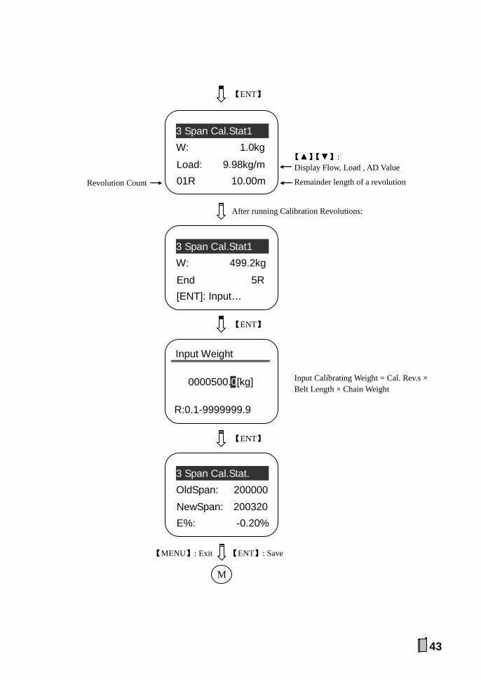
Remainder length of a revolution
Load: 9.98kg/m
01R 10.00m
3 Span Cal.Stat1 W: 1.0kg
Revolution Count
【▲】【▼】: Display Flow, Load , AD Value
【ENT】
After running Calibration Revolutions:
End 5R [ENT]: Input…
3 Span Cal.Stat1
W: 499.2kg
【ENT】
0000500.0[kg]
R:0.1-9999999.9
Input Weight
【MENU】: Exit 【ENT】: Save
【ENT】
M
NewSpan: 200320
E%: -0.20%
3 Span Cal.Stat.
OldSpan: 200000
Input Calibrating Weight = Cal. Rev.s × Belt Length × Chain Weight

44
6.4.4 Static Span Calibration with Hanging Weight
Keep the belt weigher running with loading hanging weights for correcting Span Coefficient. Put a measured hanging weight as a steady load on the belt weigher and then start belt weigher.
05[R]
R: 1-99
P110 Cal. Revs
Main Display Interface
【MENU】+【▲】【▼】: F2 Calibration 【ENT】+【▲】【▼】:4 Span Cal.Stat2 【ENT】
M
【ENT】
0010.0[kg]
R: 0.1-1000.0
P112 HangWeight
【ENT】
01.000 [m]
R: 0.001-50.000
P113 WeighLength
【ENT】

45
0000500.0[kg]
R:0.1-9999999.9
Input Weight
【MENU】: Exit 【ENT】: Save
【ENT】
M
NewSpan: 200320
E%: -0.16%
4 Span Cal.Stat2
OldSpan: 200000
Input Calibrating Weight = Cal. Rev.s × Belt Length × Chain Weight / Weigh Length
Remainder length of a revolution
Load: 9.98kg/m
01R 10.00m
4 Span Cal.Stat2 W: 1.0kg
Revolution Count
【▲】【▼】: Display Flow, Load , AD Value
After running Calibration Revolutions:
End 5R
[ENT]: Input…
4 Span Cal.Stat2 W: 499.2kg
【ENT】

46
6.4.5 Segmenting Span Correction
After doing Dynamic or Static Span Calibration, further corrections for 3 [AD Value: 0~60000] linear segments are optional for correcting Correction Coefficient 1~3.
【ENT】& Start loading
Remainder length of a revolution AD: 26080
01R 9.90m
5 Span Cor. Seg. W: 1.0kg
Revolution Count
【▲】【▼】: Display Flow, Load or AD Value
0: SEG1
R: 0-2
Linear Segment AD Value Linear Segment 1~3 SEG1: 0~[P119] SEG2: [P119]~[P120] SEG3: [P120]~Max. AD Value
AD: 26080
Wait… 1.00m
5 Span Cor. Seg. W: 245.0kg
Stop loading &【ENT】
After running the last revolution:
Main Display Interface
【MENU】+【▲】【▼】: F2 Calibration 【ENT】+【▲】【▼】:5 Span Cor. Seg. 【ENT】
M
End 5R [ENT]: Input…
5 Span Cor. Seg. W: 249.5kg

47
New COR1: 1.002 E%: -0.20%
5 Span Cor. Seg. Old COR1: 1.000
【ENT】
【ENT】
000250.0[kg]
R: 0.1-9999999.9
Input Weight
[P121]/[P122]/[P123] Span Correction Coefficient: 0.500~2.000
【MENU】: Exit 【ENT】: Save
M

48
6.4.6 Speed Calibration
Keep the belt weigher running at a constant speed. After the belt running time of a revolution being measured by stopwatch, do this operation for correcting Speed Coefficient.
0010.00 [m]
R: 0.01-5000.00
P102 Belt Length
Main Display Interface
【MENU】+【▲】【▼】: F2 Calibration 【ENT】+【▲】【▼】: 6 Speed Cal. 【ENT】
M
Run-timer over
New: 100.0pl/m Pulse: 980
6 Speed Cal. Old: 100.0pl/m
【MENU】: Exit 【ENT】: Save
M
[P103]: Speed Cofficient [pulse/m]
【ENT】
0028.0 [s]
R: 1.0-9999.9
Run-timer
Length: 10.00m
Timer: 27.0s
6 Speed Cal. Pulse: 35
【ENT】
Pulse Count
Belt Length Set value
49
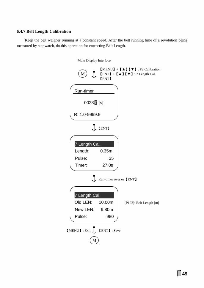
6.4.7 Belt Length Calibration
Keep the belt weigher running at a constant speed. After the belt running time of a revolution being measured by stopwatch, do this operation for correcting Belt Length.
New LEN: 9.80m Pulse: 980
7 Length Cal. Old LEN: 10.00m
【ENT】
[P102]: Belt Length [m]
Main Display Interface
【MENU】+【▲】【▼】: F2 Calibration 【ENT】+【▲】【▼】: 7 Length Cal. 【ENT】
M
Pulse: 35
Timer: 27.0s
7 Length Cal. Length: 0.35m
0028.0 [s]
R: 1.0-9999.9
Run-timer
Run-timer over or【ENT】
【MENU】: Exit 【ENT】: Save
M

50
6.5 F3 Weight Record for Querying&Printing
Weight records per shift/day/month of a year can be queried and printed.
2005-05-20
Input Date
F3 Weight Record
【PRINT】: Print weight records from the first day of this month to this day. See Appendix A.Table 3
Day: 470030kg
Mon: 8080030kg
2009-05-20Record 3rd: 190150kg
【PRINT】: Print weight records of this day See Appendix A.Table 2
【ENT】
3rd: 190150kg
Day: 470030kg
2009-05-20Record 2nd: 169900kg
2nd: 169900kg 3rd: 190150kg
2009-05-20Record 1st: 109980kg 【▲】【▼】: Previous/next record
【ADJ-】【ADJ+】: Previous/next day 【PRINT】: Print weight record of this shift
See Appendix A.Table 1
Main Display Interface
【MENU】+【▲】【▼】: F3 Weight Record 【ENT】
M
M
【MENU】
51
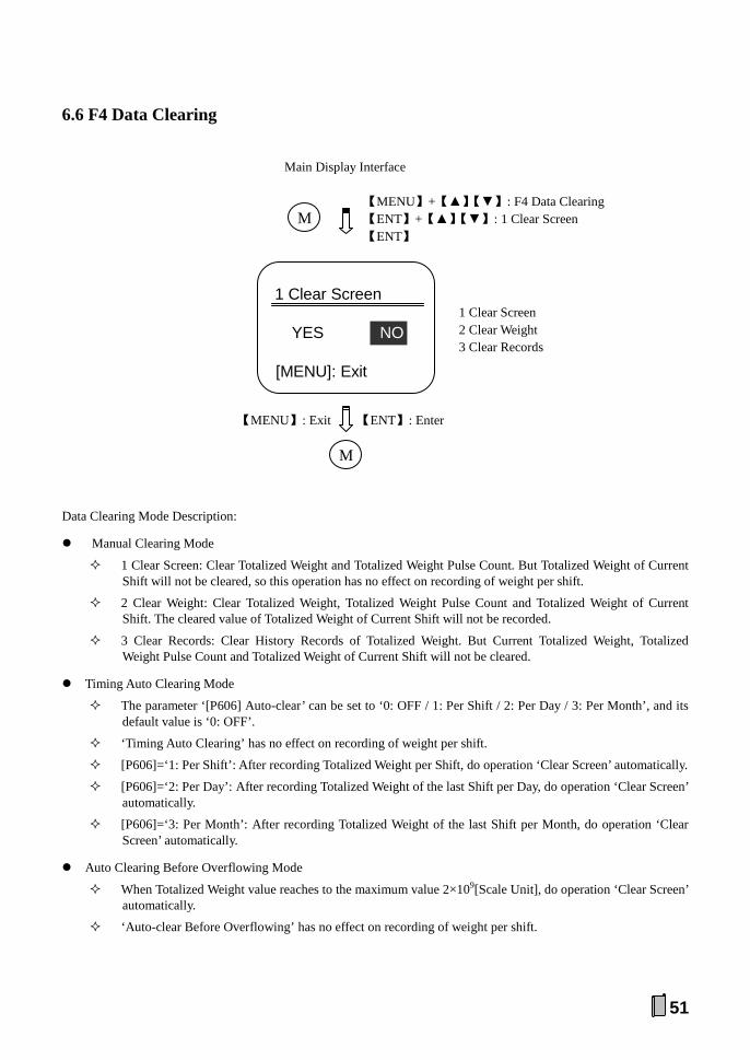
6.6 F4 Data Clearing
Data Clearing Mode Description:
Manual Clearing Mode
1 Clear Screen: Clear Totalized Weight and Totalized Weight Pulse Count. But Totalized Weight of Current Shift will not be cleared, so this operation has no effect on recording of weight per shift.
2 Clear Weight: Clear Totalized Weight, Totalized Weight Pulse Count and Totalized Weight of Current Shift. The cleared value of Totalized Weight of Current Shift will not be recorded.
3 Clear Records: Clear History Records of Totalized Weight. But Current Totalized Weight, Totalized Weight Pulse Count and Totalized Weight of Current Shift will not be cleared.
Timing Auto Clearing Mode
The parameter ‘[P606] Auto-clear’ can be set to ‘0: OFF / 1: Per Shift / 2: Per Day / 3: Per Month’, and its default value is ‘0: OFF’.
‘Timing Auto Clearing’ has no effect on recording of weight per shift.
[P606]=‘1: Per Shift’: After recording Totalized Weight per Shift, do operation ‘Clear Screen’ automatically.
[P606]=‘2: Per Day’: After recording Totalized Weight of the last Shift per Day, do operation ‘Clear Screen’ automatically.
[P606]=‘3: Per Month’: After recording Totalized Weight of the last Shift per Month, do operation ‘Clear Screen’ automatically.
Auto Clearing Before Overflowing Mode
When Totalized Weight value reaches to the maximum value 2×10⁹[Scale Unit], do operation ‘Clear Screen’ automatically.
‘Auto-clear Before Overflowing’ has no effect on recording of weight per shift.
YES NO
[MENU]: Exit
1 Clear Screen
Main Display Interface
【MENU】+【▲】【▼】: F4 Data Clearing 【ENT】+【▲】【▼】: 1 Clear Screen 【ENT】
M
【MENU】: Exit 【ENT】: Enter
M
1 Clear Screen 2 Clear Weight 3 Clear Records
52
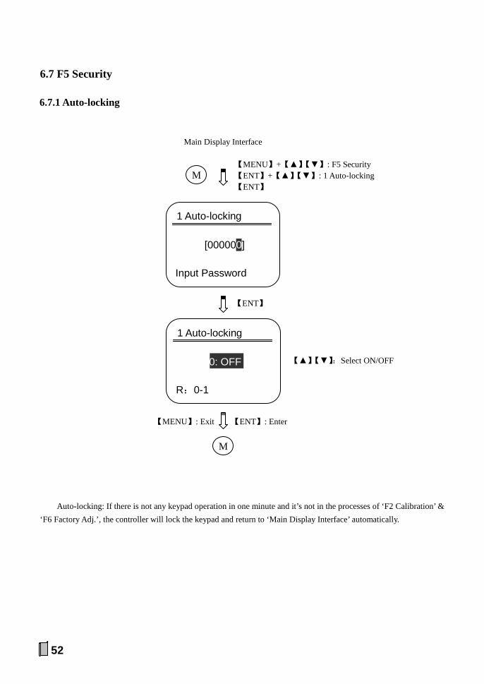
6.7 F5 Security
6.7.1 Auto-locking
Auto-locking: If there is not any keypad operation in one minute and it’s not in the processes of ‘F2 Calibration’ & ‘F6 Factory Adj.’, the controller will lock the keypad and return to ‘Main Display Interface’ automatically.
[000000]
Input Password
1 Auto-locking
Main Display Interface
【MENU】+【▲】【▼】: F5 Security 【ENT】+【▲】【▼】: 1 Auto-locking 【ENT】
M
【MENU】: Exit 【ENT】: Enter
M
【▲】【▼】:Select ON/OFF
【ENT】
0: OFF
R:0-1
1 Auto-locking
53
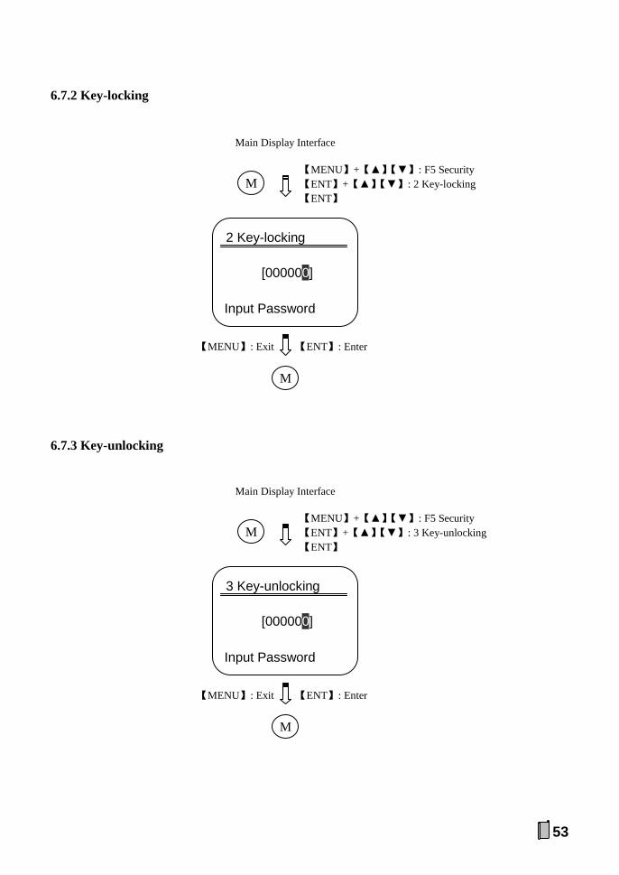
6.7.2 Key-locking
6.7.3 Key-unlocking
[000000]
Input Password
3 Key-unlocking
Main Display Interface
【MENU】+【▲】【▼】: F5 Security 【ENT】+【▲】【▼】: 3 Key-unlocking 【ENT】
M
【MENU】: Exit 【ENT】: Enter
M
[000000]
Input Password
2 Key-locking
Main Display Interface
【MENU】+【▲】【▼】: F5 Security 【ENT】+【▲】【▼】: 2 Key-locking 【ENT】
M
【MENU】: Exit 【ENT】: Enter
M

54
6.7.4 Password Set
Please remember it.
[000000]
Old Password
4 Password Set
Main Display Interface
【MENU】+【▲】【▼】: F5 Security 【ENT】+【▲】【▼】: 4 Password Set 【ENT】
M
【MENU】: Exit 【ENT】: Save
M
[000000]
New Password
4 Password Set
【ENT】

55
6.7.5 RAM Reset
YES NO
[MENU]: Exit
5 RAM Reset
Main Display Interface
【MENU】+【▲】【▼】: F5 Security 【ENT】+【▲】【▼】: 5 RAM Reset 【ENT】
M
【MENU】: Exit 【ENT】: Enter
M

56
7. Ration Flow Auto-Feeding System
AI.Flow Setpoint
Frequency Convertor & Relays
AO.Corntrol Current
IPC/ PLC
RS485/RS232/RS422/Profibus-DP/Ethernet
AO.Corntrol Current
DO.Feeder Control
DO.Belt Weigher Control
AO.Flow
)
PLC/IPC
DI/DO/AO: Definable. AO3: If you need it, inform us in your order.
Belt Weigher Speed Sensor
Feeder
Loadcell
Wei
ghin
g Si
gnal
Spee
d Si
gnal
Summing Box
DI. Start
COM
DI. System Ready
DI. Stop
Diverter Switch
Reset Button
DO.Alarm
Controller

57
Appendix A. Print Formats
Print Format A:
Table 1. Weight Record For A Shift (SW)
WEIGHT RECORD -------------------------- DATE: 2009-05-20 NAME: SW TW: 109980kg -------------------------- 2009-05-20 23:59
Table 2. Weight Record For A Day (DW)
WEIGHT RECORD -------------------------- DATE: 2009-05-20 NAME: 1W TW: 109980kg DATE: 2009-05-20 NAME: 2W TW: 169900kg DATE: 2009-05-20 NAME: 3W TW: 190150kg DATE: 2009-05-20 NAME: DW TW: 470030kg -------------------------- 2009-05-20 23:59
Table 3. Weight Record For A Month (MW)
WEIGHT RECORD -------------------------- DATE: 2009-05-01 NAME: DW TW: 387090kg DATE: 2009-05-02 NAME: DW TW: 568800kg 。。。 。。。 DATE: 2009-05-20 NAME: DW TW: 470030kg DATE: 2009-05-20 NAME: MW TW: 8080030kg -------------------------- 2009-05-20 23:59

58
Print Format B:
Table 1. Weight Record For A Shift (SW)
WEIGHT RECORD -------------------------------------------------- DATE NAME WEIGHT 2009-05-20 SW 109980kg -------------------------------------------------- 2009-05-20 23:59
`
Table 2. Weight Record For A Day (DW)
WEIGHT RECORD -------------------------------------------------- DATE NAME WEIGHT 2009-05-20 1W 109980kg 2009-05-20 2W 169900kg 2009-05-20 3W 190150kg 2009-05-20 DW 470030kg -------------------------------------------------- 2009-05-20 23:59
Table 3. Weight Record For A Month (MW)
WEIGHT RECORD -------------------------------------------------- DATE NAME WEIGHT 2009-05-01 DW 387090kg 2009-05-02 DW 568800kg 2009-05-03 DW 190150kg 。。。 。。。 。。。 2009-05-20 DW 470030kg 2009-05-20 MW 8080030kg -------------------------------------------------- 2009-05-20 23:59
Appendix B. Communication Protocols
If you need the communication protocols, please contact us.


Changsha Supmeter Technological Co.,Ltd.
Address: Building A6, Lugu International Industrial Park, Changsha, 410205, China
Tel: +86 731 85115100 Fax: +86 731 85158100 Website: www.supmeter.com.cn E-mail: [email protected]