bsi british standards - nottinghamshire county · pdf fileraising standards worldwide™ p...
TRANSCRIPT

raising standards worldwide™
NO COPYING WITHOUT BSI PERMISSION EXCEPT AS PERMITTED BY COPYRIGHT LAW
BSI British Standards
WB9423_BSI_StandardColCov_noK_AW:BSI FRONT COVERS 5/9/08 12:55 Page 1
Code of practice for noise and vibration control on construction and open sites –Part 2: Vibration
BS 5228-2:2009
Lice
nsed
Cop
y: M
rs. F
iona
Rog
erso
n, A
tkin
s, 2
9/01
/200
9 23
:45,
Unc
ontr
olle
d C
opy,
(c)
BS
I

BS 5228-2:2009 BritiSh Standard
Publishing and copyright information
the BSi copyright notice displayed in this document indicates when the document was last issued.
© BSi 2008
iSBn 978 0 580 56049 1
iCS 17.140.20
the following BSi references relate to the work on this standard: Committee reference B/564/1 draft for comment 08/30141422 dC
Publication history
First published as BS 5228, May 1975 First published as BS 5228-1, BS 5228-2 and BS 5228-3, May 1984 Second edition of BS 5228-1, BS 5228-2 and BS 5228-3, May 1997 First edition of BS 5228-4, January 1986 Second edition of BS 5228-4, May 1992 First edition of BS 5228-5, november 1997 Present (third) edition in two parts, december 2008
Amendments issued since publication
Amd. No. Date Text affected
Lice
nsed
Cop
y: M
rs. F
iona
Rog
erso
n, A
tkin
s, 2
9/01
/200
9 23
:45,
Unc
ontr
olle
d C
opy,
(c)
BS
I
BritiSh Standard
© BSI 2008 • i
BS 5228-2:2009
ContentsForeword iii1 Scope 12 normative references 13 terms and definitions 14 Community relations 25 Vibration and persons on site 26 neighbourhood nuisance 37 Project supervision 58 Control of vibration 89 Measurement 22
Annexesannex a (informative) Legislative background 25annex B (normative) Significance of vibration effects 35annex C (informative) Measured vibration levels for piling (current data) 43annex d (informative) Measured vibration levels for piling (historic data) 44annex E (informative) Prediction of vibration levels 71annex F (informative) description of vibration 75annex G (informative) air overpressure 81annex h (informative) Examples of record sheets 83
Bibliography 85
List of figuresFigure a.1 – Procedures to control construction vibration under the Control of Pollution act 1974 28Figure B.1 – transient vibration guide values for cosmetic damage 38Figure B.2 – Example of vibration criteria 41Figure E.1 – Scaled distance graph 74Figure F.1 – Sketch plan illustrating potential vibration measurement locations 80Figure h.1 – Site measurements sheet 83Figure h.2 – Vibration data summary sheet 84
List of tablestable B.1 – Guidance on effects of vibration levels 36table B.2 – transient vibration guide values for cosmetic damage 38table B.3 – Key to vibration criteria illustrated in Figure B.2 42table C.1 – Summary of case history data on vibration levels 43table d.1 – Summary of historic case history data on vibration levels measured during impact bored piling (tripod) 45table d.2 – Summary of historic case history data on vibration levels measured during driven cast-in-place piling (drop hammer) 48table d.3 – Summary of historic case history data on vibration levels measured during dynamic consolidation 51table d.4 – Summary of historic case history data on vibration levels measured during vibroflotation/vibroreplacement 55table d.5 – Summary of historic case history data on vibration levels measured during the use of casing vibrators 59table d.6 – Summary of historic case history data on vibration levels measured during rotary bored piling (including casing dollies) 61table d.7 – Summary of historic case history data on vibration levels measured during tripod bored piling 62table d.8 – Summary of historic case history data on vibration levels measured during driven sheet steel piling 63
Lice
nsed
Cop
y: M
rs. F
iona
Rog
erso
n, A
tkin
s, 2
9/01
/200
9 23
:45,
Unc
ontr
olle
d C
opy,
(c)
BS
I

BS 5228-2:2009
ii • © BSI 2008
BritiSh Standard
table d.9 – Summary of historic case history data on vibration levels measured during driving of bearing piles 65table d.10 – Summary of historic case history data on vibration levels measured during use of vibratory pile drivers 67table d.11 – Summary of miscellaneous historic case history data on vibration levels measured during piling and kindred operations 69table E.1 – Empirical predictors for groundborne vibration arising from mechanized construction works 72table E.2 – Values of kp for use in predictions of vibration from percussive piling 73
Summary of pagesthis document comprises a front cover, an inside front cover, pages i to iv, pages 1 to 90, an inside back cover and a back cover.
Lice
nsed
Cop
y: M
rs. F
iona
Rog
erso
n, A
tkin
s, 2
9/01
/200
9 23
:45,
Unc
ontr
olle
d C
opy,
(c)
BS
I

BritiSh Standard
© BSI 2008 • iii
BS 5228-2:2009
Foreword
Publishing information
this part of BS 5228 is published by BSi and came into effect on 1 January 2009. it was prepared by Subcommittee B/564/1, Noise control working group, under the authority of technical Committee B/564, Noise control on construction and open sites. a list of organizations represented on this committee can be obtained on request to its secretary.
Supersession
together with BS 5228-1:2008, this part of BS 5228 supersedes BS 5228-1:1997, BS 5228-2:1997, BS 5228-3:1997, BS 5228-4:1992 and BS 5228-5:1997, which are withdrawn.
Relationship with other publications
BS 5228 is published in two parts:
Part 1: • Noise;
Part 2: • Vibration.
BS 6472 gives detailed guidance on human response to vibration in buildings and BS 7385-1 covers the measurement and evaluation of structural vibration. BS 7385-2 contains guidance on damage levels from groundborne vibration.
an item dealing with the vibratory loading of structures, iSO/FdiS 10317, is being processed within iSO technical Committee iSO/tC 98/SC/2, Safety of structures. this is being monitored by BSi.
Information about this document
this British Standard refers to the need for the protection against noise and vibration of persons living and working in the vicinity of, and those working on, construction and open sites. it recommends procedures for noise and vibration control in respect of construction operations and aims to assist architects, contractors and site operatives, designers, developers, engineers, local authority environmental health officers and planners.
noise and vibration can cause disturbance to processes and activities in neighbouring buildings, and in certain extreme circumstances vibration can cause or contribute to building damage.
noise and vibration can be the cause of serious disturbance and inconvenience to anyone exposed to it and in certain circumstances noise and vibration can be a hazard to health. attention is drawn to the legislation summarized in annex a.
this is a full revision of this part of BS 5228, and introduces the following principal changes:
restructuring of the standard into two parts, one dealing with • noise and one with vibration;
updating of information relating to legislative requirements;•
updating of information relating to methods and equipment.•
NOTE Copyright is claimed in Tables E.1 and E.2. The copyright holder is the Transport Research Laboratory (TRL), Crowthorne House, Nine Mile Ride, Wokingham, Berkshire, RG40 3GA.
Lice
nsed
Cop
y: M
rs. F
iona
Rog
erso
n, A
tkin
s, 2
9/01
/200
9 23
:45,
Unc
ontr
olle
d C
opy,
(c)
BS
I
BS 5228-2:2009
iv • © BSI 2008
BritiSh Standard
Use of this document
as a code of practice, this part of BS 5228 takes the form of guidance and recommendations. it should not be quoted as if it were a specification and particular care should be taken to ensure that claims of compliance are not misleading.
any user claiming compliance with this part of BS 5228 is expected to be able to justify any course of action that deviates from its recommendations.
Presentational conventions
the provisions in this standard are presented in roman (i.e. upright) type. its recommendations are expressed in sentences in which the principal auxiliary verb is “should”.
Commentary, explanation and general informative material is presented in smaller italic type, and does not constitute a normative element.
Contractual and legal considerations
this publication does not purport to include all the necessary provisions of a contract. Users are responsible for its correct application.
Compliance with a British Standard cannot confer immunity from legal obligations.
Lice
nsed
Cop
y: M
rs. F
iona
Rog
erso
n, A
tkin
s, 2
9/01
/200
9 23
:45,
Unc
ontr
olle
d C
opy,
(c)
BS
I
BritiSh Standard
© BSI 2008 • 1
BS 5228-2:2009
1 Scopethis part of BS 5228 gives recommendations for basic methods of vibration control relating to construction and open sites where work activities/operations generate significant vibration levels, including industry-specific guidance.
the legislative background to vibration control is described and recommendations are given regarding procedures for the establishment of effective liaison between developers, site operators and local authorities.
Guidance is provided concerning methods of measuring vibration and assessing its effects on the environment.
2 Normative referencesthe following referenced documents are indispensable for the application of this document. For dated references, only the edition cited applies. For undated references, the latest edition of the referenced document (including any amendments) applies.
BS 3015, Glossary of terms relating to mechanical vibration and shock
3 Terms and definitionsFor the purposes of this part of BS 5228, the definitions given in BS 3015 and the following apply.
3.1 air overpressureairborne pressure waves generated by blasting, produced over a range of frequencies including those which are audible and those which are below the lower end of the audible spectrum
3.2 amplification factormotion measured at a given point (usually on the structure), divided by the motion measured at a reference point (usually at the base of the structure or on the foundation)
3.3 peak particle velocity (PPV)instantaneous maximum velocity reached by a vibrating element as it oscillates about its rest position
3.4 overburdenmaterial overlying the coal, or mineral or minerals to be extracted, including topsoil and subsoil
3.5 pilinginstallation or removal of bored, driven and pressed-in piles and the effecting of ground treatments by vibratory, dynamic or other methods of ground stabilization
3.6 vibration dose value (VDV)measure of the total vibration experienced over a specified period of time
NOTE Air overpressure can be quantified either as a pressure or as a level in linear (unweighted) decibels (dB).
NOTE Economic deposits of other minerals can occur in the overburden.
Lice
nsed
Cop
y: M
rs. F
iona
Rog
erso
n, A
tkin
s, 2
9/01
/200
9 23
:45,
Unc
ontr
olle
d C
opy,
(c)
BS
I
BS 5228-2:2009
2 • © BSI 2008
BritiSh Standard
NOTE The VDV can be determined for continuous, intermittent, occasional and impulsive vibration. It takes account of the magnitude of the vibration events and the number and duration of those events, to quantify the total vibration exposure. The VDV is given by the fourth root of the integral of the fourth power of the acceleration after it has been frequency‑weighted and is defined as:
VdVb/d, day/night =
∫ a t dt
T4
0
0 25
( )
.
where:
VDVb/d, day/night is the vibration dose value (in m·s−1.75);
a(t) is the frequency‑weighted acceleration (in m·s−2), using Wb or Wd as appropriate;
T is the total period of the day or night, in seconds (s), during which vibration can occur.
Further details of the VDV are given in BS 6472‑1.
4 Community relationsGood relations with people living and working in the vicinity of site operations are of paramount importance. Early establishment and maintenance of these relations throughout the carrying out of site operations will go some way towards allaying people’s fears.
it is suggested that good relations can be developed by keeping people informed of progress and by treating complaints fairly and expeditiously. the person, company or organization carrying out work on site should appoint a responsible person to liaise with the public. the formation of liaison committees with members of the public can be considered for longer term projects when relatively large numbers of people are involved.
Vibration and air overpressure from blasting operations is a special case and can under some circumstances give rise to concern or even alarm to persons unaccustomed to it. the adoption of good blasting practices will reduce the inherent and associated impulsive noise: prior warning to members of the public, individually if necessary, is important.
5 Vibration and persons on site
5.1 TrainingNOTE Attention is drawn to Regulation 8 of the Control of Vibration at Work Regulations 2005 [2], which requires employers to provide information and training where the risk assessment indicates a potential risk to the health of employees as a result of exposure to vibration [either hand–arm vibration (HAV) or whole body vibration (WBV)] or where the employees are likely to be exposed to vibration levels above the relevant action levels. The Regulations require all employees to be advised of the following, as part of their training:
the organizational and technical measures to be taken in order to a) comply with the requirements of Regulation 6;
the exposure limit values and action values set out in Regulation 4;b)
the significant findings of the risk assessment, including any c) measurements taken, with an explanation of those findings;
NOTE The government has published research on the environmental effects of noise from blasting [1].
Lice
nsed
Cop
y: M
rs. F
iona
Rog
erso
n, A
tkin
s, 2
9/01
/200
9 23
:45,
Unc
ontr
olle
d C
opy,
(c)
BS
I
BritiSh Standard
© BSI 2008 • 3
BS 5228-2:2009
why and how to detect and report signs of injury;d)
entitlement to appropriate health surveillance under Regulation 7 e) and its purpose;
safe working practices to minimize exposure to vibration; andf)
the collective results of any health surveillance undertaken in g) accordance with Regulation 7 in a form calculated to prevent those results from being identified as relating to a particular person.
Operatives should be trained to employ appropriate techniques to keep site vibration to a minimum, and should be effectively supervised to ensure that best working practice in respect of vibration reduction is followed.
a programme of monitoring should be implemented to ensure that condition limits are not exceeded and that all the relevant recommendations are met.
5.2 Protection from vibration exposureExposure to prolonged and regular work with high-vibration hand held tools can be a serious hazard to health. Workers using such equipment can suffer various forms of adverse effects, collectively known as hand–arm vibration syndrome (haVS). the best known effect is vibration white finger (VWF) which is a prescribed industrial disease. Exposure to high levels of whole body vibration (WBV), e.g. for drivers of certain mobile plant in rough terrain conditions, can also be a serious hazard to health.
at present, there is no effective personal protective equipment to alleviate the exposure to haV that is comparable to ear protectors in relation to noise. Operators of hand tools known to generate high levels of vibration are advised, however, to wear suitable gloves, especially when working in cold or damp conditions, as these conditions can exacerbate the symptoms of haVS.
5.3 Vibration-induced stressVibration can interfere with working efficiency by inducing stress, by disturbing concentration and by increasing accident risk. Effects of vibration on persons on site are similar to, albeit far greater than, the effects on nearby residents, and the benefits of good control measures will apply equally on and off site.
6 Neighbourhood nuisance
6.1 Disturbing effects of vibrationVibrations, even of very low magnitude, can be perceptible to people and can interfere with the satisfactory conduct of certain activities, e.g. delicate procedures in hospital operating theatres, use of very sensitive laboratory weighing equipment. Vibration nuisance is frequently associated with the assumption that, if vibrations can be felt, then damage is inevitable; however, considerably greater levels of vibration are required to cause damage to buildings and structures (see, for example, BS 7385-2) or to cause computers and similar electronic equipment to malfunction. Vibrations transmitted from site activities to the neighbourhood can, therefore, cause anxiety as well
NOTE With the advent of the Control of Vibration at Work Regulations 2005 [2], there are now specific legal duties imposed on employers in respect of both HAV and WBV (see Note to 5.1). Useful guidance on these matters is contained within the Health and Safety Executive publications L140 [3] and L141 [4]. Applying the advice given in this guidance is expected, in the view of HSE, to ensure that the risks from HAV and/or WBV are properly controlled in accordance with the Regulations.
Lice
nsed
Cop
y: M
rs. F
iona
Rog
erso
n, A
tkin
s, 2
9/01
/200
9 23
:45,
Unc
ontr
olle
d C
opy,
(c)
BS
I
BS 5228-2:2009
4 • © BSI 2008
BritiSh Standard
as annoyance, and can disturb sleep, work or leisure activities. in any neighbourhood, some individuals will be more sensitive to vibration than others.
the significance of vibration effects should be assessed in accordance with annex B.
6.2 Site vibration descriptorsthe peak particle velocity (PPV) is the simplest indicator of both perceptibility and the risk of damage to structures. BS 7385-1 and BS 7385-2 provide guidance on measurement, evaluation of effects on buildings, and damage levels, and are based upon use of the PPV.
the vibration dose value (VdV) is recommended in BS 6472 as the appropriate measure to evaluate human exposure to vibration in buildings in residential and other uses. the likelihood of adverse comment occurring from building occupants is used to evaluate the likely severity of effect.
For damage to structures, it is preferable to undertake measurements externally at the foundations; for human exposure, measurements are usually taken within a building at the position at which the occupant experiences the vibration. if vibration measurements are taken remote from the buildings or structures of concern, then they should be corrected for distance to those buildings or structures. When internal levels are required to be predicted, then a transfer function is needed to correct the external level to the internal location of interest. in order to obtain a typical value of PPV, and/or to derive a VdV representative of a 16 h daytime or 8 h night-time period, a representative number of cycles or operations should be monitored.
Whichever measure is used to describe vibration from the site, it should always be made clear to which period of time any particular value applies.
6.3 Issues associated with vibration effects and community reactiona number of factors are likely to affect the acceptability of vibration arising from construction sites and the degree of control necessary. these are described as follows:
Site locationa) . the location of a site in relation to vibration-sensitive receptors will be a major factor. the nearer a site is to sensitive premises, the more control that might be required upon vibration emanating from the site.
Existing ambient vibration levelsb) . there is no known relationship between response and levels when comparing newly intruding and ambient vibrations. however, ambient vibrations are rarely significant or even perceptible and hence it is rarely necessary to consider the change in level.
Duration of site operationsc) . in general, the longer the duration of activities on a site, the more likely it is that vibration from the site will prove to be an issue. in this context, good public relations and communication are important. Local residents might be willing to accept higher levels of vibration if they know that such levels will only last for a short time. it is then important that site
Lice
nsed
Cop
y: M
rs. F
iona
Rog
erso
n, A
tkin
s, 2
9/01
/200
9 23
:45,
Unc
ontr
olle
d C
opy,
(c)
BS
I
BritiSh Standard
© BSI 2008 • 5
BS 5228-2:2009
operations are carried out according to the stated schedule and that the community is informed of their likely durations.
Hours of workd) . Sensitivity to vibration at different times of the day is far more complex than sensitivity to noise. the sensitivity of the human body to vibration varies according to the direction and frequency of the vibration. the guidance given in BS 6472 is useful, but when construction activities are of a temporary nature, situations will exist, both during the day and night, where vibration magnitudes above those generally corresponding to a low probability of adverse comment level can be tolerated. however, adverse community reaction is sometimes based upon concern over building damage, even when the vibration is just perceptible. it is therefore important to assure the community that vibration levels generally have to be of significant magnitude for even cosmetic damage to occur. (See also 8.6.7.)
Attitude to the site operatore) . it is well established that people’s attitudes to vibration can be influenced by their attitudes to the source or activity itself. Vibration from a site will tend to be accepted more readily by local residents, if they consider that the contractor is taking all possible measures to avoid unnecessary vibration. the attitude to the contractor can also be improved through good community liaison and information distribution and the provision of a helpline to respond to queries or complaints. the acceptability of the project itself can also be a factor in determining community reaction.
Vibration characteristicsf) . the characteristics of vibration, e.g. whether it is continuous, intermittent or impulsive, can influence its acceptability.
Effect on buildingsg) . this has been mentioned above [in item d)] but account should also be taken of the effect of vibration on buildings adjacent to the site. Guidance on the evaluation of these effects is provided in BS 7385-1, and guidance on damage levels from groundborne vibration is given in Clause 8 and BS 7385-2.
7 Project supervision
7.1 Generalthe intention throughout any construction programme should be to minimize the effects of site vibration whilst having due regard to the practicability and economic implication of any proposed control or mitigation measures.
Planners, developers, architects, engineers and environmental health officers can all assist in avoiding potentially excessive vibration levels. this can be achieved by giving careful consideration to the design of a proposed project, the processes and equipment implied by the design and the phasing of operations.
NOTE The Construction (Design and Management) Regulations 2007 [5] came into effect on 6 April 2007. They replace the Construction (Design and Management) Regulations 1994 [6] and the Construction (Health, Safety and Welfare) Regulations 1996 [7]. HSE publication L144 [8] provides practical guidance on complying with the duties set out in the Regulations.
Lice
nsed
Cop
y: M
rs. F
iona
Rog
erso
n, A
tkin
s, 2
9/01
/200
9 23
:45,
Unc
ontr
olle
d C
opy,
(c)
BS
I
BS 5228-2:2009
6 • © BSI 2008
BritiSh Standard
The key aims of these are to integrate health and safety into the management of the project and to encourage everyone involved to work together to:
improve the planning and management of projects from the very a) start;
identify risks early on so that they can be eliminated or reduced at b) the design or planning stage and the remaining risks can be properly managed;
target effort where it can do the most good in terms of health and c) safety; and
discourage bureaucracy.d)
developers, architects and engineers will need to know whether the processes they intend using are likely to be permitted. therefore an early consultation should be made with local authorities in order to ascertain the limits or restrictions, if any, likely to be imposed. annexes C and d give some guidance on levels of vibration from piling and blasting.
Local authorities should ensure that any vibration level limits or restrictions being imposed are necessary and practicable.
7.2 Works preparationa project design should be so arranged that the number of operations likely to be particularly disturbing is kept to a minimum. designers should also remember that project designs can have considerable influence upon operators’ use of sites. Project designs should include the location of items such as haulage roads, crushing plants and compaction plant.
appropriate investigations into ground conditions should be made when preliminary surveys are being carried out in order that consideration can be given to methods of working which could avoid problems.
a survey of the immediate neighbourhood surrounding a site should be undertaken to indicate the location of sensitive areas.
Guidance should be sought concerning recommended vibration levels for the neighbourhood surrounding a site, and concerning acceptance of the proposed methods of working, in very general terms, from the relevant authorities at the same time as approvals are being requested for the commencement of work. this procedure is intended to enable work to proceed smoothly.
When works involve a tender stage, details of consents or other restrictions should be given to tenderers as early as possible.
When a number of site operators will be working on one site, overall site operations should be coordinated. Preferred routes for off-site movement of vehicles should be established with the local highway authority and the police. access traffic should be routed away from sensitive premises.
tenderers for a project should select the most appropriate plant in order that limits will not be exceeded. they should also be aware of the extent of control measures that will be necessary so that appropriate cost allowances can be made.Li
cens
ed C
opy:
Mrs
. Fio
na R
oger
son,
Atk
ins,
29/
01/2
009
23:4
5, U
ncon
trol
led
Cop
y, (
c) B
SI
BritiSh Standard
© BSI 2008 • 7
BS 5228-2:2009
tenderers should satisfy themselves that proposed methods of working and phasing of operations will meet the local authority’s requirements. they should be clear about this before submitting their tenders.
tenderers should take due regard of the following before tendering:
site layout, e.g. location of static vibration sources;a)
types of machinery likely to be used and whether alternative b) types or techniques would achieve less disturbance;
the location and nature of adjacent vibration-sensitive areas.c)
7.3 Execution of worksall available techniques should be used to minimize, as far as is appropriate, the level of vibration to which operators and others in the neighbourhood of site operations will be exposed.
Measures which should be taken include the following.
the hours of working should be planned and account should a) be taken of the effects of vibration upon persons in areas surrounding site operations and upon persons working on site, taking into account the nature of land use in the areas concerned, the duration of work and the likely consequence of any lengthening of work periods.
Where reasonably practicable, low vibration working methods b) should be employed. Consideration should be given to use of the most suitable plant, reasonable hours of working for operations which might give rise to perceptible vibrations, and economy and speed of operations.
Vibration should be controlled at source and the spread of c) vibration should be limited, in accordance with Clause 8.
Where processes could potentially give rise to significant levels of d) vibration, on-site vibration levels should be monitored regularly by a suitably qualified person appointed specifically for the purpose, particularly if changes in machinery or project designs are introduced. a method of vibration measurement should be agreed prior to commencement of site works, e.g. that specified in BS 7385-1.
On those parts of a site where high levels of vibration are likely to e) be a hazard to persons working on the site, prominent warning notices should be displayed (see also Clause 5).
When potential vibration problems have been identified, or when problems have already occurred, consideration should be given to the implementation of practicable measures to avoid or minimize those problems. Local authorities, consulting with developers and their professional advisers or with site operators, will need to consider the extent of vibration control measures necessary to prevent the occurrence of significant problems, and will also need to consider whether the implementation of those measures will be practicable. Local authorities might wish to consider whether to specify quantified limits on site vibration and whether, additionally or instead, to lay down requirements relating to work programmes, plant to be used, siting of plant, periods of use, working hours, access points, etc.
NOTE The use of “best practicable means” (BPM) to control emissions can constitute a ground of defence against charges that a nuisance is being caused under Part III of the Control of Pollution Act 1974 [9] or Part III of the Environmental Protection Act 1990 [10].
Lice
nsed
Cop
y: M
rs. F
iona
Rog
erso
n, A
tkin
s, 2
9/01
/200
9 23
:45,
Unc
ontr
olle
d C
opy,
(c)
BS
I
BS 5228-2:2009
8 • © BSI 2008
BritiSh Standard
the latter approach will often be preferable in that it facilitates the monitoring of formally or informally specified requirements, both for the authorities and for the site operators.
7.4 Emergenciesin the event of any emergency or unforeseen circumstances arising that cause safety to be put at risk, it is important that every effort be made to ensure that the work in question is completed as quickly and as quietly as possible and with the minimum of disturbance to people living or working nearby. the local authority should be informed as soon as possible if it is found necessary to exceed permitted vibration limits because of an emergency.
8 Control of vibration
8.1 Generalas outlined in Clause 1, this part of BS 5228 gives recommendations for basic methods of vibration control relating to construction and open sites where work activities/operations generate significant vibration levels, including industry-specific guidance. Clause 8 is arranged so as to present generic recommendations, in 8.2, 8.3 and 8.4, followed in turn by the industry-specific guidance, which includes information relating to piling and ground engineering (8.5), the extraction of coal by open-cast methods and the surface extraction of other minerals (8.6). there is also a subclause (8.7) which addresses the issues relating to groundborne vibration and associated structure-borne noise, which arise from underground construction.
Construction and demolition activities can pose different problems of vibration control compared with most other types of industrial activity for the following reasons:
they are mainly carried out in the open;•
they are of temporary duration although they can cause great • disturbance while they last;
the vibration they cause arises from many different activities and • kinds of plant, and its intensity and character can vary greatly at different phases of the work;
the sites cannot be excluded by planning control, as factories can, • from areas that are sensitive to vibration.
if a site upon which construction or demolition work will be carried out involves an existing operational railway, special features which are significant in relation to vibration control have to be taken into account. advice should be sought in such cases from the appropriate railway authorities.
Much of the vibration from construction and demolition sites is generated by machinery. increased mechanization has brought about the use of more powerful machines, which have the potential to cause higher levels of vibration. it is now widely recognized that the vibration levels so generated are unacceptable in many instances and that reductions are necessary for the benefit of both the industry and the public.
NOTE Attention is drawn to Section 61 of the Control of Pollution Act 1974 [9], which requires provision to be made for emergencies (see A.2.3.3).
Lice
nsed
Cop
y: M
rs. F
iona
Rog
erso
n, A
tkin
s, 2
9/01
/200
9 23
:45,
Unc
ontr
olle
d C
opy,
(c)
BS
I
BritiSh Standard
© BSI 2008 • 9
BS 5228-2:2009
8.2 Control of vibration at source
8.2.1 General
Vibration can be more difficult to control than noise, and there are few generalizations which can be made about its control. it should be borne in mind that vibration can cause disturbance by causing structures to vibrate and radiate noise in addition to perceptible movement.
8.2.2 Substitution
Where reasonably practicable, plant and/or methods of work causing significant levels of vibration at sensitive premises should be replaced by other less intrusive plant and/or methods of working.
8.2.3 Vibration isolation of plant at source
Vibration from stationary plant (e.g. generators, pumps, compressors) can, in some instances, prove disturbing when located close to sensitive premises or when operating on connected structures. in these instances, equipment should be relocated or isolated using resilient mountings.
8.3 Controlling the spread of vibrationWhere reasonably practicable, vibrating equipment should be located as far from sensitive premises as possible, and, if on a structure, not on one which is continuous with that of the sensitive premises. in some instances it might be possible to reduce transmitted vibration by cutting a structure to separate site work from sensitive premises. it is essential to take account of safety and structural issues before carrying out any work of this nature.
the demolition of tall or large structures, especially if explosives are used, can give rise to impulsive vibrations and air overpressure when the felled structures hit the ground. Further advice is contained in BS 6187.
8.4 Vibration control targetsall reasonably practicable means should be employed to ensure the protection of local communities and of people on construction sites, from detrimental effects of the vibration generated by construction operations. the means employed should be determined by local circumstances and can include vibration reduction measures for individual items or plant and machinery, the fixing of hours of work, the setting of noise or vibration limits or any other appropriate measures.
those seeking to determine suitable vibration limits for construction operations should be aware of the particular noise problem that can occur when such operations take place in existing buildings that are either occupied or contiguous with occupied buildings. Vibration introduced directly into the structure by equipment such as breakers, hammers and drills might attenuate only slowly as it is transmitted through the structure and might therefore produce unacceptable levels of noise in rooms remote from the source. in particularly sensitive situations it might be necessary to use alternative techniques and equipment.
NOTE 3 See also 6.3.
NOTE The use of trenches to reduce transmitted vibration through the ground is described in 8.5.3.3.
NOTE 1 Section 60 of the Control of Pollution Act 1974 [9] specifies the matters to which local authorities will have regard when serving a notice imposing requirements to limit noise and vibration emission from sites.
NOTE 2 Annexes C and D give guidance on vibration levels produced by selected site equipment and activities and Annex E describes methods of estimating vibration. The information contained in these annexes is intended to assist with the prediction of the levels of vibration likely to emanate from a proposed construction site and to provide a useful reference when the setting of vibration limits is being considered.
Lice
nsed
Cop
y: M
rs. F
iona
Rog
erso
n, A
tkin
s, 2
9/01
/200
9 23
:45,
Unc
ontr
olle
d C
opy,
(c)
BS
I
BS 5228-2:2009
10 • © BSI 2008
BritiSh Standard
8.5 Practical measures to reduce vibrations from piling sites
8.5.1 General
the most common form of vibration associated with piling is the intermittent type derived from conventional driven piling. Each hammer blow transmits an impulse from the head to the toe of the pile and free vibrations are set up. Sensors at a remote receiving point would indicate a series of wave disturbances, each series corresponding to one blow. (See also annex F.)
When setting targets for maximum vibration levels (8.5.2), reference might need to be made to the existing baseline vibration levels, which should be measured prior to commencement of pile driving. this is particularly applicable on sites adjacent to roads carrying heavy commercial traffic, railway tracks and large industrial machinery. it is not uncommon for vibrations from such sources to mask vibrations from pile driving.
it is desirable that the planning process does not prohibit the use of any piling methods on the basis of vibration.
Where the predictions indicate that a particular piling method could prove marginal in terms of critical vibration levels, methods of alleviating the problem may be adopted as recommended in 8.5.3.
8.5.2 Vibration levels
the intensity of vibration at the point of interest will normally be a function of many variables including:
energy per blow or cycle;a)
distance between source and receiver;b)
ground conditions at the site, e.g. soft or hard driving and c) location of water table;
soil–structure interaction, i.e. nature of connection between soil d) and structure being monitored;
construction of structure and location of measuring points, for e) example:
soil surface;1)
building foundation;2)
internal structural element.3)
in soft driving conditions, where a significant proportion of the energy per blow is directly used in advancing the pile, the intensity of vibrations transmitted to the environment is generally less than under hard driving conditions, where so much of the energy per blow is devoted to overcoming resistance to penetration that relatively little is available to advance the pile.
When driving piles in soft soils, the free vibrations set up are found usually to have a greater low frequency content than when driving into denser soils or rocks.
NOTE The construction industry is generally innovative and constantly developing, and there might be proprietary systems available at the time of tender that were not known or available at the planning stage.
NOTE 1 Various empirical formulae have been proposed relating the intensity of vibration measured at the remote receiving point, to the distance between it and the source and the energy of the source. The use of such formulae enables a rough estimate to be made as a check on the acceptability of the proposed process from a vibration standpoint, prior to the commencement of the piling works. This estimate could also assist with applications under Section 61 of the Control of Pollution Act 1974 [9] for prior consent (see Annex A). For guidance regarding the prediction of expected vibration levels, see Annex E.
NOTE 2 See Annexes C and D for examples of vibration levels measured under various conditions throughout the UK.
Lice
nsed
Cop
y: M
rs. F
iona
Rog
erso
n, A
tkin
s, 2
9/01
/200
9 23
:45,
Unc
ontr
olle
d C
opy,
(c)
BS
I

BritiSh Standard
© BSI 2008 • 11
BS 5228-2:2009
8.5.3 Vibration mitigation
8.5.3.1 Use of alternative methods
Piling and ground engineering processes are primarily selected on the basis of the ground conditions to be encountered, the loads to be supported and the economics of the system. taking these constraints into account, the process should be selected that is least likely to give rise to unacceptable vibrations in particular circumstances. Examples would include the use of continuous flight auger injected piles, pressed-in preformed piles, auger bored piles, or possibly impact bored piles in preference to driven piles. Some form of ground treatment might also be possible, depending on soil conditions and loading requirements.
there are sometimes cases in which the majority of a site is amenable to a particular form of ground treatment or foundation construction but where a limited area is too close to existing structures or services to permit unrestricted use of the process. For example, from table d.3 (see annex d) it can be deduced that dynamic compaction using large tamping weights should be kept a reasonable distance away from such features. if a small intervening area remains to be treated, this may be done using one of the vibro processes of ground treatment. Similarly, the majority of a site may be piled using the driving process, leaving a minority to be completed with continuous flight auger injected piling.
it should be noted that a change in method part of the way across the site might result in a mismatch in subsequent foundation behaviour. the engineering implications of any such changes should be taken into account prior to construction on site.
When piling is to be installed close to slopes, vibration of any form can cause movement of the slope material.
When the pile type is chosen, care should be taken to avoid substituting the risk from vibration, pore pressure changes and soil displacement associated with driven piling and other systems which generate vibrations, by threats to stability resulting from uncontrolled soil removal or the release of ground water.
it is often advantageous to carry out controlled trials to establish a safe method of working, from observations of vibration intensity, of the onset of local distress to the soil face and of changes in line and level.
Where doubt about the loss of stability remains, action should be taken either to phase the work so that piling can be completed before earthworks are carried out, or to retain the soil effectively to allow piling to take place safely.
Where piling is required near to electronic installations (see annex B, B.5), an important consideration is the likely frequency range of the piling vibrations. an example from one major manufacturer quotes permitted levels for intermittent vibrations varying between 50 mm·s−1 at 8 hz and 10 mm·s−1 at 40 hz, a frequency range which covers much of that associated with piling in soils. these criteria are judged to apply to electronic equipment correctly installed on the ground floor of a building.
NOTE The extraction of piles and their ancillary equipment can also generate vibration.
Lice
nsed
Cop
y: M
rs. F
iona
Rog
erso
n, A
tkin
s, 2
9/01
/200
9 23
:45,
Unc
ontr
olle
d C
opy,
(c)
BS
I
BS 5228-2:2009
12 • © BSI 2008
BritiSh Standard
Electronic equipment is not as fragile as is often believed and, with care, piling need not pose a threat to the continued safe use of a typical electronic installation. Extra care might be needed if the installation is mounted on a suspended floor which might accentuate the level of vibration.
8.5.3.2 Removal of obstructions
Obstructions constitute a hindrance to progress and exacerbate the transmission of vibration, especially where they occur at shallow depths. Obstructions known to exist, e.g. old basement floors, old foundations, timbers, etc., should be broken out at pile or stone column positions and the excavation backfilled. Where an unexpected obstruction is encountered, it might be preferable for piling to be halted at that position until such time as the obstruction can be dealt with, rather than attempting prolonged hard driving.
Coring through existing piles and foundations is becoming more common on urban sites. Vibrations resulting from this process will need to be considered carefully.
8.5.3.3 Provision of cut-off trenches
a cut-off trench can be regarded as analogous to a noise screen, in that it interrupts the direct transmission path of vibrations between source and receiver. there are serious limitations to the efficacy of trenches. For maximum effect the trench should be as close to the source or to the receiver as possible. the trench should have suitable dimensions to mitigate vibration adequately; specialist advice should be sought to determine the appropriate dimensions. With normally available excavators on site, trench depths are seldom in excess of 4 m or 5 m.
a trench constitutes a safety hazard. Even if the ground is self-supporting, a flexible support mechanism, e.g. bentonite suspension, might be needed. Care should be exercised in designing and locating the trench to avoid any loss of support to the structure it is intended to protect or to the piles being installed. Care should also be taken to ensure that the stability of the piling equipment is not endangered by the presence of the trench.
the wall of the trench closest to the piling operation might suffer progressive collapse during the course of the works. Provided that all appropriate hazards are identified and managed, such collapse might be acceptable as an energy releasing mechanism.
at the conclusion of the relevant piling operations the trench should be appropriately backfilled.
Specialist advice should be sought prior to constructing cut-off trenches, as this option does not provide appropriate mitigation for all vibration problems.
8.5.3.4 Reduction of energy input per blow
Consideration of the relationships described in annex E suggests that there is a dependence of the PPV on the energy input for hammer-driven piles. it might therefore be possible to reduce the level of vibration caused by piling by reducing the energy input.Li
cens
ed C
opy:
Mrs
. Fio
na R
oger
son,
Atk
ins,
29/
01/2
009
23:4
5, U
ncon
trol
led
Cop
y, (
c) B
SI
BritiSh Standard
© BSI 2008 • 13
BS 5228-2:2009
the penalty for adopting this method is that more blows at lower energy will be needed to drive the piles to a required depth. the trade-off will not necessarily be linear owing to other losses in energy in the system. Use of this mitigation method, combined with vibration monitoring, might enable driving piles close to buildings with shallow foundations or in the vicinity of shallow buried services, by starting the drive with low hammer drops, subsequently increasing the energy as the toe of the pile reaches the founding stratum at greater depth.
although in general terms it is accepted that vibrations at any level can contribute to fatigue mechanisms in structures, the relative importance of vibration intensity and number of cycles at that intensity is not sufficiently understood. Under the appropriate circumstances, however, it might be more acceptable, or even preferable, to reduce the energy per blow, thus limiting the PPV but sustaining a longer period of pile driving. the effect of this approach on the degree and duration of disturbance to the building’s occupants might also need to be taken into account.
NOTE Special arrangements might be needed where piles are driven to a set. Driving to a set entails counting a number of blows from a standard height of drop (standard for the particular piling system) for a given (small) penetration, or by measuring the penetration obtained after a given number of blows from the standard height of drop. It should be borne in mind that set might not be achieved when using the lower drop height initially chosen to reduce vibration magnitude.
8.5.3.5 Reduction of resistance to penetration
8.5.3.5.1 Pre-boring for driven piles
When piles are to be driven and there is the risk of excessive vibrations emanating especially from the upper strata, the problem can sometimes be reduced by pre-boring. this process removes some of the soil which would otherwise have to be displaced in the early stages of pile driving. there is some evidence to suggest that the final level of vibration during driving would not be reduced, although there would be a reduction in the number of blows needed to achieve the proper penetration.
a variant of this procedure which can be used with top-driven cast in place piling is to commence by driving the tube open-ended. a plug of soil is formed within the tube, which is then withdrawn and the plug is removed. this can be repeated several times before the shoe is fitted and the tube driven closed-ended in the normal manner.
8.5.3.5.2 Mudding in for rotary bored piles
Whilst pre-boring is used in the construction of rotary bored piles in order to reduce the resistance of penetration of temporary casing, it is often coupled with mudding in to reduce the risk of collapse of the sides of the bore.
Following normal pre-boring, a small quantity of bentonite slurry is added to the borehole and the auger is rotated rapidly in order to stir up the slurry and any collapsed material from the unlined sides. the casing is then offered into the hole, its penetration being assisted by the lubricating action of the mud slurry. depending on conditions the final seating of the casing can be assisted either by use of a twister bar (the casing being rotated in), or by tapping with a heavy casing dolly or by using a vibrator. the use of these latter two items should, however, be minimized.
Lice
nsed
Cop
y: M
rs. F
iona
Rog
erso
n, A
tkin
s, 2
9/01
/200
9 23
:45,
Unc
ontr
olle
d C
opy,
(c)
BS
I
BS 5228-2:2009
14 • © BSI 2008
BritiSh Standard
8.5.3.5.3 Adding water to the bore hole for impact bored piles
the level of vibration from impact bored piling is generally considered acceptable and the method is occasionally used on confined sites adjacent to existing structures. the level of vibration increases with the resistance to boring and particularly when the boring tool fails to make measurable progress, e.g. in dense dry gravel. Progress can be increased by adding water to the bore, but great care is needed to ensure that the casing is advanced in pace with the boring tool and that excessive use of water is avoided to reduce overboring and the consequent risk of undermining adjacent structures.
8.5.3.6 Excavation under support fluid
an alternative procedure for bored piles using very long casings where there are substantial depths of water bearing sands and silts, is to drill the piles under support fluid.
it might then be possible to restrict casing to a relatively short length, thereby avoiding the need to resort to the use of either vibratory or percussive dollies for insertion or withdrawal.
8.5.3.7 Avoidance of shear leg contact with sensitive structures
tripod impact bored piling rigs can impart vibrations and shocks through the shear legs. Where, as is often the case, there is a confined working area for a tripod rig, care should be taken in setting up the rig at any pile position, to avoid having one of the legs or its support in direct contact with any adjacent building which might be sensitive to vibrations.
8.5.3.8 Removal of the plug when using casing vibrators
Vibratory drivers have difficulty in penetrating dense cohesionless soils (see annex F). Where such a machine is used to insert a casing into a stratum of medium dense to dense granular soil, a plug of this soil will accumulate inside the casing. the vibrator will now be confronted with additional resistance, thus slowing penetration and probably accentuating environmental vibration levels.
Provided the boring rig has a sufficiently high rotary table, it should be used to drill out the plug at intervals between short periods of vibratory driving. this procedure is expected to substantially reduce the total amount of time needed for use of the vibrator.
8.5.3.9 Bottom-driving
Bottom-driving might result in lower vibration levels than top-driving. the method can be applied to some permanently cased piles and some specialized cast-in-place systems.
the process is quieter than its top-driven counterpart; however, any reduction in vibration intensity might be associated with the generally slower rate of production.
8.5.3.10 Use of variable moment vibrators
Vibrators operate through a system of contra-rotating eccentric weights that are arranged such that the dynamic forces generated by their rotation are vertically aligned. during the start-up and run-down periods of operation, the rotational frequency undergoes continuous
Lice
nsed
Cop
y: M
rs. F
iona
Rog
erso
n, A
tkin
s, 2
9/01
/200
9 23
:45,
Unc
ontr
olle
d C
opy,
(c)
BS
I
BritiSh Standard
© BSI 2008 • 15
BS 5228-2:2009
change between the static and steady-state operating frequency. Groundborne vibration is often found to be higher during the start-up and run-down phases than during steady driving at the full operating frequency.
research undertaken by trL [11] has shown that this is related to differences in the attenuation rates of different frequencies of vibration: when the operating frequency of the vibrator corresponds with the preferred propagation frequency of the ground, the vibration is attenuated less with distance than at other, particularly higher, frequencies. the transient phases of operation can therefore affect a larger area than the vibration during steady state driving. Furthermore, the frequency sweep can pass through the resonance frequencies of elements of structures (such as floors and ceilings), leading to temporarily elevated levels of vibration.
there are clearly advantages in avoiding these transient phases of operation where groundborne vibration might be an issue. Some manufacturers supply vibrators that can be operated such that the system of eccentric weights is balanced during start-up and run-down so that all forces are equal and opposite. Once the operating frequency is reached, the phase is shifted so that vertically aligned vibration is generated as normal. Groundborne vibration is therefore largely eliminated during the start-up and run-down phases.
8.6 Practical measures to reduce vibration from surface coal extraction by opencast methods and surface mineral (except coal) extraction
8.6.1 General
Both opencast coal sites and other surface mineral extraction sites can pose a greater diversity of problems of vibration control compared with most other types of industrial activity for the following reasons.
apart from some ancillary operations, they are carried out a) entirely in the open and can extend over a wide area.
they are of variable duration from a few months to several years b) or even decades, and in some cases sites in adjacent areas can follow one another in succession over a prolonged period.
a wide variety of activities are carried out involving the following c) phases:
geological and geotechnical exploration;1)
preliminary operations to establish the site;2)
soil stripping and removal of overburden;3)
for opencast coal, coaling, coal preparation, storage and 4) dispatch; for other surface minerals, processing, e.g. washing, crushing and screening, transportation of material within sites and to markets; blasting might be required to extract coal or other minerals;
backfilling and final site restoration;5)
rehabilitation of final land form to public amenity, 6) agriculture or other subsequent development.
Lice
nsed
Cop
y: M
rs. F
iona
Rog
erso
n, A
tkin
s, 2
9/01
/200
9 23
:45,
Unc
ontr
olle
d C
opy,
(c)
BS
I
BS 5228-2:2009
16 • © BSI 2008
BritiSh Standard
a wide range of earth-moving and specialized plant is employed, d) the use of which varies significantly at different phases and times and at different heights and depths within the site. the intensity and character of any vibration and/or air overpressure can vary at different phases of work, at different times and under differing conditions of, for example, topography, geology, climate and methods of operation.
Coal and other minerals can only be worked where suitable e) resources exist. resources might be present in close proximity to premises sensitive to vibration. Under these circumstances, such premises should be protected as far as is practicable from the adverse effects of vibration.
the highest levels of vibration on these sites are generally only associated with blasting activities, although at closer range vibrations can be experienced from material processing, transport and the operation of large earthmoving machinery. Measures to control vibration are generally necessary where sites are located in the vicinity of sensitive premises, for the benefit of both the public and the industry.
Blasting might be required at opencast coal sites, but only occurs at a proportion of other surface mineral extraction sites, generally those producing crushed rock. there are particular characteristics of blasting which require specific consideration of vibration issues. Blasting creates vibration which is of very short duration, with a frequency of events varying from a small number per year to several times per day, depending on the nature and size of the extraction operation.
in addition to coal, a wide variety of different minerals is produced in Britain by surface extraction methods. the methods of working vary greatly according to the type of mineral, its geology and location and the end uses for which the mineral is intended. the nature of any impact from vibration therefore needs to be considered in the context of the relevant site-specific factors.
a typical mineral extraction operation involves stripping of topsoil and removal of overburden, excavation and processing of the material to be extracted, transportation of material within the site and to markets and subsequent restoration of the land.
Prior to making an application for planning permission, an applicant should discuss with the Mineral Planning authority (MPa) and the appropriate department of the local authority (see annex a) the predicted vibration levels from the proposed site and the control measures to be implemented. this will highlight at an early stage any vibration issues that need to be addressed. the predicted vibration levels and proposed control measures should be included in the application documentation, which should, where appropriate, also contain information on the typical existing background levels. Where a formal environmental assessment is undertaken, vibration will normally be taken into account.
Local residents and other interested parties should also be consulted at this stage.
8.6.2 Site planning
in planning the working of the site, account should be taken of the effect of the proposed working method and site layout on adjacent sensitive premises. Where necessary, alternative methods or arrangements which have the least impact of emissions of vibration should be employed if economically viable.
Lice
nsed
Cop
y: M
rs. F
iona
Rog
erso
n, A
tkin
s, 2
9/01
/200
9 23
:45,
Unc
ontr
olle
d C
opy,
(c)
BS
I
BritiSh Standard
© BSI 2008 • 17
BS 5228-2:2009
8.6.3 Location of site elements
With due consideration of the topography of the area and natural screening effects, care should be taken in the siting of the following:
access points;a)
limit of excavation;b)
coal screening and washing plants, or other mineral crushing, c) screening and washing plants, as appropriate to the site;
pumps, generators and static plant;d)
stocking areas and loading facilities;e)
off-site coal or other mineral haulage routes.f)
access points should be located with due regard to the proximity of vibration-sensitive premises.
the limit of excavation is determined by a wide range of geological and engineering constraints such as the location, nature and quality of the coal or other mineral, the characteristics and stability of the strata and the existence of faults and other features.
Site amenities, plant yards, maintenance areas, coal screening/washing plants or other mineral crushing/screening and washing plants, stocking and loading facilities should be sited as far from vibration-sensitive premises as practicable.
Where the processed coal or other mineral is to be transported from the site by road, the route should be carefully selected to minimize the impact on vibration-sensitive premises even if this results in an increased haulage distance.
8.6.4 Working methods
it is important to consider the methods of working to be adopted including the sequence and phasing of activities on site. activities that are undertaken close to vibration-sensitive properties should be programmed where practicable over a short period of time appropriate to local conditions. a common sense approach to such activities will help minimize the potential for any adverse environmental impacts. the following factors, which can have particularly significant effects, should, where relevant, be taken into account:
depth of the coal seams or other mineral deposits;a)
direction of working;b)
plant to be employed;c)
working hours;d)
rate of production;e)
use and control of blasting, including timing and frequency.f)
Once the limit of excavation and the maximum depth of the coal seams or mineral deposits to be extracted have been determined (see 8.6.3), a direction of working and phasing of operations should be deployed that reduces the transmission of vibration from the site.
there is a wide range of variables that influence these activities, therefore it is not possible to be prescriptive for individual sites.
NOTE The location and design of access points have to be agreed with the highway authority and the Mineral Planning Authority.
Lice
nsed
Cop
y: M
rs. F
iona
Rog
erso
n, A
tkin
s, 2
9/01
/200
9 23
:45,
Unc
ontr
olle
d C
opy,
(c)
BS
I
BS 5228-2:2009
18 • © BSI 2008
BritiSh Standard
8.6.5 Selection of plant
the characteristics of vibration emissions from each item of plant, and their collective effect, should be assessed during the selection process for the acquisition of plant. Where practicable, plant should be selected which will have the least impact in terms of vibration.
8.6.6 Deployment of plant
the movement of plant on and off the site should be restricted as far as practicable to within the agreed working hours for the site.
8.6.7 Hours of work
For any operation where vibration might have an adverse effect on the occupants of sensitive premises, working hours should be restricted in preference to the sterilization of coal reserves or other mineral resources. Such restrictions should only be imposed where they are necessary. it might in some circumstances be reasonable to limit particular operations or working phases to certain durations or times of the year, where this does not unduly conflict with the operation of the site. alternatively it might be more appropriate, especially when dealing with established operations, to take other practical measures for vibration reduction (see 8.6.4). Coal or other mineral haulage by road from such sites should be limited to between 07.00 h and 19.00 h, unless local circumstances require otherwise.
8.6.8 Site management
8.6.8.1 General
Good site practice depends upon suitably trained or experienced site operatives. appropriate supervision and a commitment by all concerned to keep vibration to a minimum can provide a cost-effective way of achieving the objectives of this part of BS 5228.
8.6.8.2 Operatives
Operatives should be familiar with the relevant conditions of the planning permission, details of which should be available for inspection on site at all times. the site should be operated in accordance with these conditions at all times and where practical difficulties arise discussion should be sought with the relevant authority as soon as these become apparent.
8.6.8.3 Supervision and maintenance
it is likely that vibration will be an important factor in any opencast pit or quarry plan and/or environmental management, which might also involve monitoring of site performance or more detailed audits carried out by site staff or other appropriate parties. records should be kept of any complaints received or other breaches of the controls or planning conditions relevant to vibration, in order to assist effective site management.
NOTE See also 6.3d).
Lice
nsed
Cop
y: M
rs. F
iona
Rog
erso
n, A
tkin
s, 2
9/01
/200
9 23
:45,
Unc
ontr
olle
d C
opy,
(c)
BS
I
BritiSh Standard
© BSI 2008 • 19
BS 5228-2:2009
Site supervision and maintenance are essential in ensuring that throughout its life, operations are carried out as they were intended. Plant and machinery (including measurement equipment) should be maintained in good working order and used in accordance with the manufacturer’s instructions. Special attention should be paid to any aspects which might affect the vibration likely to arise.
8.6.8.4 Transport routing
Measures should be put in place to ensure that where it is intended that both on-site and off-site lorry traffic should follow a particular route, sufficient information is provided to all drivers and other relevant staff to ensure that they are aware of their responsibilities. this can be provided by on-site signage or through other information handed to drivers.
8.6.9 Practical measures to reduce vibration and air overpressure from blasting
8.6.9.1 General
Most complaints of vibration relate to blasting. Blasting should only be used where there is no viable alternative. Groundborne vibration can lead to concern being expressed by residents around opencast sites, usually over the likelihood of damage to property. Good public relations have been shown to reassure the public of the fact that normal production blasting has not been found to damage property, and that even the most cosmetic of plaster cracking is extremely unlikely. in addition, contacting owners of sensitive properties to advise of imminent blasting can further help promote harmony with the public. it is good practice to publicize times when blasting will occur and to avoid blasting at other times whenever possible.
air overpressure from blasting comprises transient airborne pressure waves which can be heard and felt. air overpressure can be influenced by meteorological conditions over which operators have no control. although air overpressure can be affected by the total quantity of explosives deployed in a blast, there is a balance to be struck between a smaller number of large blasts and a larger number of small blasts. Public relations have an important role to play in determining the optimum balance between size and frequency of blasting.
8.6.9.2 Vibration and air overpressure reduction
Practical measures, including good blast design, that have been found to reduce air overpressure and/or vibration are:
taking particular care with the development of faces and a) with trial blasts at a quarry or opencast coal pit, as anomalous vibration levels might be produced when there is no free face to relieve the energy produced;
ensuring appropriate burden to avoid over or under confinement b) of the charge;
accurate setting out and drilling;c)
appropriate charging;d)
NOTE 1 Care needs to be taken to avoid damage to cave systems and underground passageways.
NOTE 2 Further information on ground vibration and air overpressure is given in Annexes F and G respectively.
Lice
nsed
Cop
y: M
rs. F
iona
Rog
erso
n, A
tkin
s, 2
9/01
/200
9 23
:45,
Unc
ontr
olle
d C
opy,
(c)
BS
I
BS 5228-2:2009
20 • © BSI 2008
BritiSh Standard
appropriate stemming with appropriate material such as sized e) gravel or stone chippings;
using delay detonation to ensure smaller maximum instantaneous f) charges (MiCs);
using decked charges and in-hole delays;g)
blast monitoring to enable adjustment of subsequent charges;h)
designing each blast to maximize its efficiency and reduce the i) transmission of vibration;
avoiding the use of exposed detonating cord on the surface in j) order to minimize air overpressure – if detonating cord is to be used in those cases where down-the-hole initiation techniques are not possible, it should be covered with a reasonable thickness of selected overburden.
8.6.10 Coal disposal sites
after coal is excavated from an opencast site it is sometimes taken to a coal disposal site. this can be located within an opencast site, adjacent to an opencast site or at some distance, near main line rail and road facilities, and can serve more than one site. at a coal disposal site any, all or a combination of the following can take place: coal washing, crushing, screening, blending, storage in hoppers or on the ground in bunds and dispatch from the disposal point by rail or road vehicles.
Most of these activities generate vibration. the major sources are the crushing and screening processes, the reception and disposal hoppers, mobile site plant and road and rail traffic.
Coal disposal sites are areas of major industrial activity which might need to be located at distance from vibration-sensitive areas.
8.6.11 Limitations on emissions of vibration from sites
Opencast coal and other surface mineral extraction and associated works can take place in remote to semi-urban area conditions. Each site and situation should be analysed for vibration control on its own merits. When the site is adjacent to vibration-sensitive premises it might be necessary to impose conditions including specific vibration limits.
Guidance on criteria for the setting of vibration control targets is given in annex B.
Limitations on working hours for the site, or part of it, and the restriction of the activities most likely to cause vibration to less sensitive times or days, can be employed as a means of limiting the impact of vibration from opencast coal and other surface mineral sites.
8.7 Groundborne vibration and consequent noise from sub-surface construction activitiesWhere construction works take place entirely underground and away from access or ventilation shafts, airborne noise is often completely attenuated by the overlying ground or structures. if the construction activity generates vibration at source, then both groundborne vibration and groundborne noise (or structure radiated noise) can be prominent effects experienced at the surface and within overlying buildings. Groundborne noise generated within a building is predominantly low frequency in nature and can be caused by the vibration of all
NOTE Additional conditions might also be imposed by the Secretary of State or Mineral Planning Authority as appropriate. Guidance on vibration levels associated with blasting is given within MPG 9 [12] and for noise from surface mineral workings within MPS 2 [13].
Lice
nsed
Cop
y: M
rs. F
iona
Rog
erso
n, A
tkin
s, 2
9/01
/200
9 23
:45,
Unc
ontr
olle
d C
opy,
(c)
BS
I
BritiSh Standard
© BSI 2008 • 21
BS 5228-2:2009
the internal surfaces of that building. as such, the effects can be particularly intrusive and potentially inescapable and, when combined with the simultaneous experience of perceptible vibration, can give rise to higher magnitudes of adverse comment, at a given level, than might be expected from available dose response data for more typical environmental noise sources. these particular features mean that the noise and vibration effects of underground construction activities can be a significant environmental risk to project developers.
activities which can give rise to appreciable vibration and groundborne noise include tunnel and cavern construction. tunnelling techniques vary considerably but known sources of groundborne noise include tunnel boring machines, road-headers and excavators; tunnel segmental lining placement; hydraulic drilling; use of hydraulic hammers for cavern mining; limpet vibrators; and drill-and-blast operations. depending on the progress rates and techniques employed, these effects can be relatively short-lived but might expose a sensitive receiver to high magnitudes of vibration and/or groundborne noise.
For large tunnelling projects, the transportation of excavated material from the tunnel face can be undertaken by conveyor, by lorry or by the use of a temporary railway system. these transportation systems might need to operate for several months or even years on a 24 h basis and therefore might become potential long-term concerns in relation to groundborne noise and vibration generation. a temporary railway might need to be designed from the outset to control groundborne noise and vibration generation to a similar specification, and using similar techniques, as a permanent underground railway.
the mechanisms which give rise to the propagation of vibration through media such as soil are complex. the magnitude of vibration is determined by the characteristics of the vibration source, the properties of the excavated ground, and the ground between the vibration source and receiver. Multi-layered soils and/or the presence of deep piled building foundations can further complicate and modify magnitudes and estimates. as such, it is inappropriate to provide definitive generic guidance on the likely magnitudes of groundborne noise and vibration that might be expected as a result of a particular construction technique. Estimation of the likely noise and vibration effects from sub-surface construction activities based solely on consideration of previous case studies should therefore be undertaken with caution. Calculating groundborne noise and vibration is highly specialized, and expert advice should be sought if a high degree of confidence in the predicted levels is required.
there are no standards which provide objective criteria for the assessment of the significance of groundborne noise during sub-surface construction, and expert advice should be sought on appropriate guideline levels for a specific project which take into account the duration of the project, the frequency of any events, the potential magnitude of groundborne noise, the numbers and sensitivity of buildings affected, the adopted construction technique and other relevant factors.
the Office of Planning and Environment of the US Federal transit administration (Fta) has published groundborne noise impact criteria for the general assessment of transit schemes [14]. the criteria vary according to the number of groundborne noise events likely and the sensitivity of the receiving buildings. although these criteria have been developed primarily for railway applications, they may
NOTE Research undertaken by TRL [11] provides guidance on calculating first estimates of potential vibration and groundborne noise levels from mechanized bored tunnelling works.
Lice
nsed
Cop
y: M
rs. F
iona
Rog
erso
n, A
tkin
s, 2
9/01
/200
9 23
:45,
Unc
ontr
olle
d C
opy,
(c)
BS
I
BS 5228-2:2009
22 • © BSI 2008
BritiSh Standard
be used as guidance for the screening or assessment of sub-surface construction activities. For frequent events, a guide maximum sound pressure level of 35 dB(a) using the “slow” time constant (inside residences and buildings where people normally sleep) is given in the Fta document for assessing the impact of long-term operation of a transit system. in some circumstances, the unfamiliar character and unknown duration and origin of construction groundborne noise can justify the application of lower guide levels than would be appropriate for long-term transportation sources, particularly if used to assess the need for mitigation initiatives.
Mitigation options for mechanized tunnelling activities are limited. in some circumstances, it might be possible to limit working hours, but in every case where the risk of widespread unacceptable disturbance exists, a comprehensive and informative community relations programme should be formulated and implemented well in advance of the approaching works. this can be particularly effective for tunnelling works, since the source is not visible and the effects are quite unlike those to which the general public is commonly exposed, which exacerbates concerns. On certain tunnelling projects it might be possible to control the vibration at source by limiting the rotational speed of the cutting face or the thrust force and progress rate of the tunnel boring machine.
Mitigation options for a temporary construction railway include restricting the speed of the vehicles; controlling the wheel/rail roughness by grinding or conditioning; limiting and avoiding misaligned or worn rail joints; and the provision of resilient layers beneath the rails and/or beneath an entire temporary sleeper assembly.
in some circumstances, the exposure to groundborne noise and vibration at residential dwellings can render the building unoccupiable and can warrant the temporary relocation of occupants, particularly when night-time working is required.
9 MeasurementNOTE Guidance on measurement of vibration for assessing human disturbance is given in BS 6472, and for building damage in BS 7385‑1.
9.1 Monitoringin order to ensure optimum control of vibration, monitoring should be regarded as an essential operation. in addition to vibration monitoring, static tell-tale measurements can also be useful. Precision tell-tales are capable of registering longer term trends and can provide early warning of impending structural problems. Failures, sometimes catastrophic, can occur as a result of conditions not directly connected with the transmission of vibrations, e.g. the removal of supports from retaining structures to facilitate site access.
Where site activities other than pile driving can affect existing structures, a thorough engineering appraisal of the situation should be made at the planning stage. information on monitoring of vibrations is included in annex F.
Lice
nsed
Cop
y: M
rs. F
iona
Rog
erso
n, A
tkin
s, 2
9/01
/200
9 23
:45,
Unc
ontr
olle
d C
opy,
(c)
BS
I
BritiSh Standard
© BSI 2008 • 23
BS 5228-2:2009
9.2 Methods of measurement
9.2.1 General
the method selected to characterize building vibration will depend upon the purpose of the measurement and the way in which the results are intended to be used. although a measurement technique which records unfiltered time histories allows any desired value to be extracted at a later stage, it might not be strictly necessary for the purpose of routine monitoring.
9.2.2 Positions
the number of measurement positions will depend upon the size and complexity of the building.
When the purpose is to assess the possibility of structural damage, the preferred primary position is in the lowest storey of the building, either on the foundation of the outer wall, in the outer wall, or in recesses in the outer wall. For buildings having no basement, the point of measurement should be not more than 0.5 m above ground level. For buildings with more than one storey, the vibration might be amplified within the building. in the case of horizontal vibration, such amplification might be in proportion to the height of the building, whereas vertical vibration tends to increase away from walls, towards the mid-point of suspended floors.
it might therefore be necessary to carry out measurements (which should be simultaneous if a transfer function is required) at several positions to record maximum vibration magnitudes. When the building is higher than four floors (approximately 12 m) additional measuring points should be added every four floors and at the top of the building. When the building is more than 10 m long, the measuring positions should be selected at a horizontal spacing not exceeding 10 m. Measurements should be made on the side of the building facing the source.
When the purpose is to evaluate human exposure to vibration in the building, or to assess the effect of vibration on sensitive equipment within the building, measurements should be taken on the structural surface supporting the human body or the sensitive equipment.
When ground vibration sources are being considered, it is usual to orientate the transducers with respect to the radial direction, defined as the line joining the source to the transducer.
When studying structural response to ground vibration, it is more usual to orientate transducers with respect to the major and minor axes of the building structure.
if it is not possible to make measurements at the foundation, transducers should be well coupled to the ground.
9.2.3 Parameter to measure
With an impulsive source of vibration, it is recommended to measure the peak value attained from the beginning to the end of a drive. it is also recommended to measure in terms of PPV if the risk of damage to the building is the primary concern, and there is also an interest
NOTE Information is given in BS 7385‑1.
Lice
nsed
Cop
y: M
rs. F
iona
Rog
erso
n, A
tkin
s, 2
9/01
/200
9 23
:45,
Unc
ontr
olle
d C
opy,
(c)
BS
I
BS 5228-2:2009
24 • © BSI 2008
BritiSh Standard
in human reaction. if the concern is purely for human tolerance, then weighted acceleration is the preferred parameter. in the case of sensitive equipment, it is necessary to check the environmental vibration limit data supplied by the manufacturer and select accordingly.
a survey of the sensitivity of the neighbourhood to vibration is desirable.
9.2.4 Record sheets
an important aspect of monitoring vibrations is the preparation and maintenance of records of salient details of the site observations. the format should be determined according to the circumstances appropriate to each investigation.
9.2.5 Trial measurements
the various formulae which have been developed empirically to predict vibration levels at a receiving point do not take into account variability of ground strata, the pile-soil interaction process, coupling between the ground and the foundations, etc. hence these formulae can only provide a first assessment of whether or not the vibrations emanating from a site are likely to constitute a problem.
More accurate assessment can be achieved by the calibration of the site, i.e. the establishment of a site-specific formula. in the case of impact pile driving, the data necessary for the derivation of the formula can be obtained from one or more trial drive(s) using a piling rig, and recording the vibration levels at various distances from the pile position.
trial blasting should be undertaken where practicable on sites where blasting methods are to be used, to assist in the calibration of the site.
Vibration measurements may also be taken on structures to provide information on the coupling between the soil and the foundations and amplification effects within a building. a range of impact energies should be used to encompass the energy levels associated with the intended piling works.
NOTE Annex H contains examples of pro forma record sheets for site measurements and for vibration data summaries which have been devised for a multi‑channel digital data acquisition system.
Lice
nsed
Cop
y: M
rs. F
iona
Rog
erso
n, A
tkin
s, 2
9/01
/200
9 23
:45,
Unc
ontr
olle
d C
opy,
(c)
BS
I
BritiSh Standard
© BSI 2008 • 25
BS 5228-2:2009
Annex A (informative) Legislative background
A.1 Statutory controls over vibration
Citizens have a right to seek redress through common law action in the courts against the intrusion of unreasonable levels of noise or vibration which might affect their premises. in addition, there are two significant statutory remedies which enforcing authorities can employ to achieve the following two similar objectives:
enforcement action to prevent or secure the abatement of a a) statutory nuisance; and
use of specific national legislation to control vibration from b) construction sites and other similar works.
Part iii of the Environmental Protection act 1990 [10] contains the mandatory powers available to local authorities within England and Wales in respect of any vibration which either constitutes or is likely to cause a statutory nuisance. Section 79 of this act defines statutory nuisance and places a duty on a local authority to inspect the area to detect any statutory nuisances which ought to be dealt with under Section 80. Under this section, where a local authority is satisfied of the existence, recurrence or likely occurrence of a statutory nuisance, it has to serve an abatement notice on the appropriate person or persons. Failure to comply with the terms of this notice is an offence which can result in proceedings in a Court of Summary Jurisdiction.
Section 82 of the Environmental Protection act permits the court to act on a complaint by any person who might be aggrieved by the existence of a statutory nuisance and in these circumstances the court might follow the procedures described in the previous paragraph. Similar procedures to the above, for the control, in Scotland, of statutory nuisances caused by vibration, are found under Sections 58 and 59 of the Control of Pollution act 1974 [9]. in northern ireland the relevant equivalent provisions are contained in the Pollution Control and Local Government (northern ireland) Order 1978 [15].
Sections 60 and 61 of the Control of Pollution act 1974 [9] give local authorities in England, Scotland and Wales special powers for controlling vibration arising from construction and demolition works on any building or civil engineering sites. in northern ireland, equivalent powers are contained in the Pollution Control and Local Government (northern ireland) Order 1978 [15]. Powers under Sections 60 and 61 and their equivalent in northern ireland are confined to construction, including maintenance and repair, and to demolition works carried out on all building structures and roads. they are described in detail in A.2.3.
Under Part iii of the Control of Pollution act 1974 [9], Section 71 requires the Secretary of State to approve a code of practice for the execution of works which come within the scope of Section 60.
A.2 UK Acts and Regulations
A.2.1 Health and Safety at Work etc. Act 1974
the protection of employed persons is covered by the health and Safety at Work etc. act 1974 [16].
Lice
nsed
Cop
y: M
rs. F
iona
Rog
erso
n, A
tkin
s, 2
9/01
/200
9 23
:45,
Unc
ontr
olle
d C
opy,
(c)
BS
I
BS 5228-2:2009
26 • © BSI 2008
BritiSh Standard
Section 2 of the act requires all employers to ensure, so far as is reasonably practicable, the health, safety and welfare at work of all their employees. Section 3 concerns employers’ duties to persons not in their employment who might be exposed to health and safety risks. Section 6 requires designers, manufacturers, importers or suppliers to ensure, so far as is reasonably practicable, that articles for use at work are so designed and constructed as to be safe and without risks to health when properly used, that any necessary research to this end is carried out and that adequate information on the safe use of the articles is made available.
Section 7 places a duty on employees to take reasonable care for the health and safety of themselves and of other persons who might be affected, and to co-operate with their employers, so far as is necessary to enable any duty or requirement to be performed or complied with. in northern ireland, equivalent powers are contained in the health and Safety at Work (northern ireland) Order 1978 [17].
A.2.2 Control of Vibration at Work Regulations 2005
the Control of Vibration at Work regulations 2005 [2] implement directive 2002/44/EC [18].
the regulations apply to both hand–arm vibration (haV) and whole body vibration (WBV). the main requirements are triggered by two “action levels”, one each for haV and for WBV and two “limit levels”, one each for haV and for WBV. the values of these levels and limits are expressed in terms of daily exposure to frequency and time weighted acceleration related to 8 h of 2.5 m·s−2 as the exposure action level and 5.0 m·s−2 as the exposure limit level for haV, and 0.5 m·s−2 as the exposure action level and 1.15 m·s−2 as the exposure limit level for WBV (regulation 4).
regulation 5 imposes a duty on the employer to carry out risk assessments in the work place. regulation 6 requires the employer to control or reduce the risk of exposure to vibration. regulation 7 requires the employer to conduct health surveillance, where the risk assessment indicates that there is potential for harm to the employee, and requires the employee to cooperate with health surveillance. regulation 8 relates to the implementation of a suitable programme of information and training on the hazards of exposure to mechanical vibration.
NOTE These Regulations were made under the Health and Safety at Work etc. Act 1974 [16].
A.2.3 Control of Pollution Act 1974 and Environmental Protection Act 1990
A.2.3.1 General
the Control of Pollution act 1974 [9] and the Environmental Protection act 1990 [10] give local authorities powers for controlling vibration from construction sites and other similar works. these powers can be exercised either before works start or after they have started. in northern ireland, similar provision is made in the Pollution Control and Local Government (northern ireland) Order 1978 [15]. Under the 1974 act, contractors, or persons arranging for works to be Li
cens
ed C
opy:
Mrs
. Fio
na R
oger
son,
Atk
ins,
29/
01/2
009
23:4
5, U
ncon
trol
led
Cop
y, (
c) B
SI
BritiSh Standard
© BSI 2008 • 27
BS 5228-2:2009
carried out, also have the opportunity to take the initiative and ask local authorities to make their vibration control requirements known. Because of an emphasis upon answering vibration questions before work starts, implications exist for traditional tender and contract procedures (see A.2.3.4).
the procedures available under the Control of Pollution act 1974 [9] for the control of construction vibration are illustrated in the flow diagram shown in Figure a.1.
A.2.3.2 Notice under Section 60 of the Control of Pollution Act 1974
Section 60 of the Control of Pollution act 1974 [9] enables a local authority, in whose area work is going to be carried out, or is being carried out, to serve a notice of its requirements for the control of site noise on the person who appears to the local authority to be carrying out the works and on such other persons appearing to the local authority to be responsible for, or to have control over, the carrying out of the works.
this notice can perform the following functions.
Specify the plant or machinery that is or is not to be used. a) however, before specifying any particular methods or plant or machinery, the local authority has to consider the desirability, in the interests of the recipient of the notice in question, of specifying other methods or plant or machinery that will be substantially as effective in minimizing noise and vibration and that will be more acceptable to the recipient.
Specify the hours during which the construction work can be b) carried out.
Specify the level of noise and vibration that can be emitted c) from the premises in question or at any specified point on those premises or that can be emitted during the specified hours.
Provide for any change of circumstances. an example of such d) a provision might be that if ground conditions change and do not allow the present method of working to be continued then alternative methods of working should be discussed with the local authority.
in serving such a notice, a local authority takes account of the following:
the relevant provisions of any code of practice issued and/or 1) approved under Part iii of the Control of Pollution act 1974 [9];
the need for ensuring that the best practicable means are 2) employed to minimize noise and vibration. “Best practicable means” recognizes that there are technical and financial limits on action that might reasonably be required to abate a nuisance;
other methods, plant or machinery that might be equally 3) effective in minimizing noise and vibration, and be more acceptable to the recipient of the notice;
the need to protect people in the neighbourhood of the site from 4) the effects of noise and vibration.
Lice
nsed
Cop
y: M
rs. F
iona
Rog
erso
n, A
tkin
s, 2
9/01
/200
9 23
:45,
Unc
ontr
olle
d C
opy,
(c)
BS
I
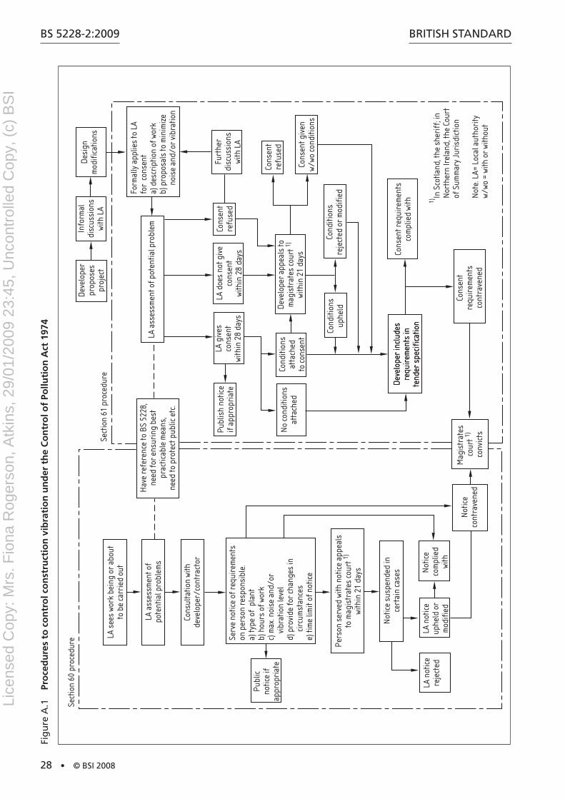
BS 5228-2:2009
28 • © BSI 2008
BritiSh StandardFi
gu
re a
.1
Pro
ced
ure
s to
co
ntr
ol c
on
stru
ctio
n v
ibra
tio
n u
nd
er t
he
Co
ntr
ol o
f Po
lluti
on
Act
197
4
Hav
e re
fere
nce
to B
S 52
28,
need
for
ensu
ring
bes
tpr
actic
able
mea
ns,
need
to p
rote
ct p
ublic
etc
.
LA a
sses
smen
t of p
oten
tial p
robl
em
Dev
elop
erpr
opos
espr
ojec
t
Info
rmal
disc
ussi
ons
with
LA
Des
ign
mod
ific
atio
ns
Form
ally
app
lies
to L
Afo
r co
nsen
ta)
des
crip
tion
of w
ork
b) p
ropo
sals
to m
inim
ize
n
oise
and
/or
vibr
atio
n
Cons
ent
refu
sed
LA d
oes
not g
ive
cons
ent
with
in 2
8 da
ys
LA g
ives
cons
ent
with
in 2
8 da
ys
Furt
her
disc
ussi
ons
with
LA
Cons
ent g
iven
w/wo
cond
ition
s
Cond
ition
sre
ject
ed o
r m
odif
ied
Cond
ition
sup
held
Cond
ition
sat
tach
edto
cons
ent
No
cond
ition
sat
tach
ed
Publ
ish
notic
eif
app
ropr
iate
Dev
elop
er a
ppea
ls to
mag
istr
ates
cour
t 1)
with
in 2
1 da
ys
Cons
ent
refu
sed
Dev
elop
er in
clud
esre
quir
emen
ts in
tend
er s
peci
fica
tion
Dev
elop
er in
clud
esre
quir
emen
ts in
tend
er s
peci
fica
tion
Cons
ent
requ
irem
ents
cont
rave
ned
Cons
ent r
equi
rem
ents
com
plie
d wi
th
Not
ice
cont
rave
ned
Not
ice
susp
ende
d in
cert
ain
case
s
Pers
on s
erve
d wi
th n
otic
e ap
peal
sto
mag
istr
ates
cour
t 1)
with
in 2
1 da
ys
Publ
icno
tice
ifap
prop
riat
e
Serv
e no
tice
of r
equi
rem
ents
on p
erso
n re
spon
sibl
e.a)
type
of
plan
tb)
hou
rs o
f wor
kc)
max
. noi
se a
nd/o
r
vib
ratio
n le
vel
d) p
rovi
de fo
r ch
ange
s in
cir
cum
stan
ces
e) ti
me
limit
of n
otic
e
Cons
ulta
tion
with
deve
lope
r/co
ntra
ctor
LA a
sses
smen
t of
pote
ntia
l pro
blem
s
LA s
ees
work
bei
ng o
r ab
out
to b
e ca
rrie
d ou
t
Sect
ion
60 p
roce
dure
Sect
ion
61 p
roce
dure
Mag
istr
ates
co
urt 1)
conv
icts
LA n
otic
ere
ject
edLA
not
ice
uphe
ld o
rm
odif
ied
Not
ice
com
plie
dwi
thIn
Sco
tland
, the
she
riff
; in
Nor
ther
n Ir
elan
d, th
e Co
urt
of S
umm
ary
Juri
sdic
tion
Not
e. L
A= L
ocal
aut
hori
tyw/
wo =
with
or
with
out
1)
Lice
nsed
Cop
y: M
rs. F
iona
Rog
erso
n, A
tkin
s, 2
9/01
/200
9 23
:45,
Unc
ontr
olle
d C
opy,
(c)
BS
I
BritiSh Standard
© BSI 2008 • 29
BS 5228-2:2009
a person served with such a notice can appeal to a magistrates court or, in Scotland, a Sheriff or, in northern ireland, a Court of Summary Jurisdiction, within 21 days from the date of serving of the notice. normally the notice is not suspended pending an appeal unless it requires some expenditure on works and/or the noise or vibration in question arises or would arise in the course of the performance of a duty imposed by law on the appellant. the regulations governing appeals also give local authorities discretion not to suspend a notice even when one or other of these conditions is met, if the noise is injurious to health, or is of such limited duration that a suspension would render the notice of no practical effect; or if the expenditure necessary on works is trivial compared to the public benefit expected. the regulations governing appeals are:
the Control of noise (appeals) regulations 1975 [19];•
the Statutory nuisance (appeals) regulations 1990 [20] • as amended;
in northern ireland, the Control of noise (appeals) regulations • (northern ireland) 1978 [21];
in Scotland, the Control of noise (appeals) (Scotland) • regulations 1983 [22]).
A.2.3.3 Consents under Section 61 of the Control of Pollution Act 1974
Section 61 of the Control of Pollution act 1974 [9] concerns the procedure adopted when a contractor (or developer) takes the initiative and approaches the local authority to ascertain its noise and vibration requirements before construction work starts. (See also A.2.3.2.)
it is not mandatory for applications for consents to be made, but it will often be in the interest of a contractor or an employer or their agents to apply for a consent, because once a consent has been granted, a local authority cannot take action under Section 60 of the Control of Pollution act 1974 [9] or Section 80 of the Environmental Protection act 1990 [10], so long as the consent remains in force and the contractor complies with its terms. Compliance with a consent does not, however, mean that nuisance action cannot be taken under Section 82 of the Environmental Protection act 1990 or under common law. a consent can be used as a defence in appeals against an abatement notice [Statutory nuisance (appeals) regulations 1990 [20] as amended].
an application for a consent has to be made at the same time as, or later than, any request for approval under the Building regulations 2000 [23], the Building Standards (Scotland) regulations 1990 [24] or the Building regulations (northern ireland) 2000 [25], or for a warrant under Section 6 of the Building (Scotland) act 2003 [26], when this is relevant. Subject to this constraint, there are obvious advantages in making any application at the earliest possible date. there might be advantages in having informal discussions before formal applications are made.
an applicant for a consent is expected to give the local authority as much detail as possible about the works to which the application relates and about the method or methods by which the work is to be carried out. information also has to be given about the steps that will be taken to minimize noise and vibration resulting from the works.
Lice
nsed
Cop
y: M
rs. F
iona
Rog
erso
n, A
tkin
s, 2
9/01
/200
9 23
:45,
Unc
ontr
olle
d C
opy,
(c)
BS
I
BS 5228-2:2009
30 • © BSI 2008
BritiSh Standard
Provided that a local authority is satisfied that proposals (accompanying an application) for minimizing noise and vibration are adequate, it will give its consent to the application. it can, however, attach conditions to the consent, or limit or qualify the consent, to allow for any change in circumstances and to limit the duration of the consent. if a local authority fails to give its consent within 28 days of an application being lodged, or if it attaches any conditions or qualification to the consent that are considered unnecessary or unreasonable, the applicant concerned can appeal to a magistrates court within 21 days from the end of that period.
When a consent has been given and the construction work is to be carried out by a person other than the applicant for the consent, applicant is required to take all reasonable steps to bring the terms of consent to the notice of that other person; failure to observe the terms of a consent is deemed to be an offence under the Control of Pollution act 1974 [9].
Section 61 also requires provision to be made for emergencies.
A.2.3.4 Contractual procedures
it is likely to be to the advantage of a developer or contractor, or an employer or its agent, who intends to carry out construction or demolition work, to take the initiative and apply to the local authority for consents under the Control of Pollution act 1974 [9].
an employer or its agent can choose to place the responsibility on the contractor to secure the necessary consents and can impose this requirement through formal contractual arrangements.
this could have implications for traditional tender and contract procedures because the local authority’s noise and vibration requirements (in addition to any separate requirements defined by the employer) can be ill-defined at tendering and contract award stage. in these circumstances, any tendering contractor needs to endeavour to identify, quantify and accommodate the level of risk (in terms of both construction methodology and cost) prior to participating in the tendering process.
When a person for whom construction work is to be carried out has already sought and obtained consent from the local authority, the local authority’s requirements need to be incorporated in the tender documents so that tenderers are aware of any apparent constraints arising from the consent.
A.2.4 Land Compensation Act 1973 (as amended), Highways Act 1980, Land Compensation, (Scotland) Act 1973, Land Acquisition and Compensation (Northern Ireland) Order 1973
the noise insulation regulations 1975 [27], noise insulation (Scotland) regulations 1975 [28] and noise insulation (northern ireland) regulations 1995 [29] made under the powers contained respectively in the Land Compensation act 1973 [30], the Land Compensation (Scotland) act 1973 [31] and the Land acquisition and Compensation (northern ireland) Order 1973 [32], allow a highway Li
cens
ed C
opy:
Mrs
. Fio
na R
oger
son,
Atk
ins,
29/
01/2
009
23:4
5, U
ncon
trol
led
Cop
y, (
c) B
SI
BritiSh Standard
© BSI 2008 • 31
BS 5228-2:2009
authority to provide insulation for dwellings and other buildings used for residential purposes by means of secondary glazing and special ventilation when highway works are expected to cause serious noise effects for a substantial period of time. the 1973 acts also contain provisions that enable a highway authority to pay the reasonable expenses of residents who, with the agreement of the authority, have to find suitable alternative accommodation for the period during which construction work makes continued occupation of an adjacent dwelling impracticable.
the highways act 1980 [33] and the Land Compensation (Scotland) act 1973 [31] enable highway authorities to acquire land by agreement when its enjoyment is seriously affected by works of highway construction or improvement. in addition, these acts give the highway authority power to carry out works, e.g. the installation of noise barriers, to mitigate the adverse effects of works of construction or improvement on the surroundings of a highway.
A.2.5 The Noise Insulation (Railways and Other Guided Transport Systems) Regulations 1995
the noise insulation (railways and Other Guided transport Systems) regulations 1995 [34] give a discretionary power to railway authorities to provide insulation or grant for insulation where noise from the construction of a new or altered railway is expected seriously to affect residential and other buildings for a substantial time.
A.2.6 Other relevant UK legislation
A.2.6.1 Surface coal extraction by opencast methods
Opencast coal mining is governed by a wide variety of legislative instruments and government policy statements. Policy regarding the working of opencast coal is set out in a series of guidance notes on mineral planning. the most important of these is MPG 3 [35], which covers all aspects of the coal industry. Other important notes are MPS 1 [36], dealing with general principles, MPG 9 [12], which contains some guidance on vibration levels associated with blasting, and MPS 2 [13], annexes 1 and 2.
the legislative framework consists of several elements, the most important of which is the Coal industry act 1994 [37]. Other key legislation includes the Coal industry nationalisation act 1946 [38], the Opencast Coal act 1958 [39], the town and Country Planning act 1990 [40] and the Planning and Compulsory Purchase act 2004 [41].
Before 1984 the British Coal Corporation’s sites were authorized by the Secretary of State for Energy. Since then for all opencast sites a planning permission has been required from the appropriate Mineral Planning authority (MPa) or, on appeal or in respect of a call-in, from the Secretary of State for Communities and Local Government in England or the Scottish Minister for Scotland or the Minister for Environment, Planning and Countryside for Wales as appropriate.
Lice
nsed
Cop
y: M
rs. F
iona
Rog
erso
n, A
tkin
s, 2
9/01
/200
9 23
:45,
Unc
ontr
olle
d C
opy,
(c)
BS
I
BS 5228-2:2009
32 • © BSI 2008
BritiSh Standard
Before making a planning application, the operator often undertakes extensive drilling and other explorations to prove the coal reserves. these operations are now governed by Clause 18 of the town and Country Planning (General development Procedure) Order 1995 [42]. Coal operators also require a licence from the Coal authority if they wish to explore for coal.
NOTE Almost all coal in Great Britain is vested in the Coal Authority, a non‑departmental public body created by the Coal Industry Act 1994 [37]. The authority is responsible for managing the non‑operational aspects of the UK coal industry.
Since July 1988 almost all the British Coal Corporation’s site applications and many larger sites applied for by other operators have been accompanied by an Environmental Statement. these are required under the town and Country Planning (Environmental impact assessment) (England and Wales) regulations 1999 [43]. the Environmental Statement examines the environmental implications of the proposed operations (noise, dust, visual impact, traffic, etc.) on the local community as well as the impact on the ecology and landscape of the site.
the MPa considers the application and, if satisfied that the proposals are acceptable in planning and environmental terms, approves it subject to conditions governing the site operations and restoration.
if the planning application is refused or not determined by the MPa, the operator can appeal to the Secretary of State for Communities and Local Government in England, the Minister for Environment, Planning and Countryside in Wales, or the Scottish Minister in Scotland, as appropriate. a public inquiry is held under an inspector, and following the inspector’s report the Secretary of State in England or relevant Minister in Wales or Scotland, as appropriate, grants or refuses permission.
after an opencast site receives planning permission, an authorization from the local authority is also needed for the coal loading operations, which are Part B processes in accordance with the regulations under Part i of the Environmental Protection act 1990 [10].
all future coal mining operations will require a lease and licence from the Coal authority under Part ii of the Coal industry act 1994 [37]. Sites licensed by the British Coal Corporation before 31 October 1994 under Section 36 (2) of the Coal industry nationalisation act 1946 [38] (as amended by the Coal industry act 1994), can, however, continue operations during the validity of those licences. Sites contained in the 1994 privatization packages have licences granted by the Government.
the previous limitation of 250 000 t on the amount of coal extracted from any one licensed opencast site was removed by the Coal industry act 1994.
applicants for licences are responsible for securing the planning permission and other consents needed to work the coal, including rights to occupy the land and to disturb other minerals. Many opencast sites win significant quantities of other minerals, principally seams of fireclay beneath the coal seams. these operations also require planning permission.Li
cens
ed C
opy:
Mrs
. Fio
na R
oger
son,
Atk
ins,
29/
01/2
009
23:4
5, U
ncon
trol
led
Cop
y, (
c) B
SI
BritiSh Standard
© BSI 2008 • 33
BS 5228-2:2009
A.2.6.2 Surface mineral extraction (except coal) sites
the principal legislation controlling the use of land for surface mineral extraction in Great Britain is provided by the town and Country Planning act 1990 [40] and the town and Country Planning (Scotland) act 1972 [44], both of which have been amended by the Planning and Compensation act 1991 [45].
the primary planning legislation in northern ireland is the Planning (northern ireland) Order 1991 [46]. acts of Parliament, rules and orders which are of relevance include the Environment act 1995 [47] and the Planning and Compulsory Purchase act 2004 [41]. there is also separate legislation controlling pollution, waste and statutory nuisance, much of which is now contained in the Environmental Protection act 1990 [10].
the relevant planning authorities are as follows:
England: county councils, metropolitan borough councils, a) unitary authorities, the national park authorities and the broads authority, where appropriate;
Wales: the unitary planning authorities and national park b) planning boards where appropriate;
Scotland: the local authority;c)
northern ireland: department of the Environment for northern d) ireland.
in England, the Secretary of State for Communities and Local Government is responsible for setting out government policy on mineral extraction in a range of Planning Policy and Minerals Planning Guidance notes. MPS 1 [36] sets out overarching national planning policies for all minerals. it has an associated practice guide [48].
in Wales, general policy is supplemented by Welsh Office guidance. Policy guidance in Scotland is provided by the Scottish Office in national Planning Policy Guidelines (nPPGs) and circulars, and advice on best practice in Planning advice notes (Pans). nPPG 4 [49] and Pan 50 [50] are of particular relevance to this standard. the Secretary of State for Communities and Local Government in England, the Scottish Minister for Scotland, and the Minister for Environment, Planning and Countryside in Wales, all have powers as defined by the legislation in relation to the submission of planning applications, determination of appeals and in respect of development plans.
Most minerals in Britain are privately owned and are worked by commercial operating companies. Sometimes, however, ownership of the land is divorced from the rights to extract the mineral. Mineral extraction, as a form of development, requires planning permission in order to be undertaken; guidance on the procedures being contained within MPG 2 [51], MPG 8 [52] and MPG 9 [12]. the Mineral Planning authorities (MPas), or on appeal the Secretary of State, will consider and either approve or refuse mineral planning applications according to their decision as to the acceptability of the proposals. in the case of an appeal, a public inquiry might be held and the inspector (reporter in Scotland) might determine the appeal or make a recommendation to the Secretary of State. all planning permissions are subject to conditions controlling relevant aspects of the development, including noise and vibration.
Lice
nsed
Cop
y: M
rs. F
iona
Rog
erso
n, A
tkin
s, 2
9/01
/200
9 23
:45,
Unc
ontr
olle
d C
opy,
(c)
BS
I

BS 5228-2:2009
34 • © BSI 2008
BritiSh Standard
A.3 Local authoritiesthe local authorities exercising powers under Part iii of the Control of Pollution act 1974 [9] and Part iii of the Environmental Protection act 1990 [10] are as follows:
in England, the council of a district or a district or a London a) borough, the Common Council of the City of London, the Sub-treasurer of the inner temple and the Under treasurer of the Middle temple;
in Wales, the council of a county or a county borough;b)
in Scotland, an islands or district council.c)
in northern ireland, district councils exercise similar functions under the Pollution Control and Local Government (northern ireland) Order 1978 [15].
the local authorities exercising planning powers are, according to the circumstances, in England, county councils or district councils, and in Scotland, the regional councils in the Borders, highland, and dumfries and Galloway regions and district or islands councils elsewhere. in northern ireland, planning control is a function of the department of the Environment (northern ireland).
For the winning and working of minerals, the relevant authority needs to be consulted as follows:
England: county councils, metropolitan boroughs, unitary • authorities and national park planning boards where appropriate;
Wales: the unitary planning authorities and national park • planning boards where appropriate;
Scotland: unitary planning authorities;•
northern ireland: department of the Environment for northern • ireland.
in the case of uncertainty as to which local authority or local authority department to consult about a vibration problem, a good starting point is often the environmental health department of the district or London borough council; in Scotland, the district or islands council; or in northern ireland, the department of Environment (northern ireland) in Belfast.
Lice
nsed
Cop
y: M
rs. F
iona
Rog
erso
n, A
tkin
s, 2
9/01
/200
9 23
:45,
Unc
ontr
olle
d C
opy,
(c)
BS
I
BritiSh Standard
© BSI 2008 • 35
BS 5228-2:2009
Annex B (normative) Significance of vibration effects
B.1 Criteria for the assessment of the significance of vibration effectsConstruction vibration assessments are generally undertaken for three main reasons:
For Environmental Impact Assessments (EIAs)a) . Most major developments now need to be assessed in accordance with the town and Country Planning (Environmental impact assessment) (England and Wales) regulations 1999 [43]. this is where the development might result in significant effects upon the environment. therefore, criteria are needed to allow these assessments to be undertaken.
Assessments for developments that do not require EIAb) . Construction vibration assessments are sometimes required by developers to advise on the likely effects that might arise and appropriate actions that might need to be taken to minimize effects.
Control of Pollution Act (CoPA) 1974 [9], Section 61, “Applications c) for prior consent for work on construction sites”. applications under this section of the CoPa are often found to be desirable and useful by both the local authority and the contractor. the applications would usually include (as identified in the CoPa):
details of the works and the method by which they are to be 1) carried out; and
the steps proposed to be taken to minimize vibration 2) resulting from the works.
By gaining consent under Section 61, the contractor gains protection from action under Section 60 of the CoPa, whereby a stop or enforcement notice cannot be served on the contractor, as long as the works are carried out in accordance with the details in the application.
this annex describes methods to identify the likely significance of vibration levels from construction and demolition activity. Further advice on the significance of vibration is given in BS 6472 and BS 7385.
B.2 Human response to vibrationhuman beings are known to be very sensitive to vibration, the threshold of perception being typically in the PPV range of 0.14 mm·s−1 to 0.3 mm·s−1. Vibrations above these values can disturb, startle, cause annoyance or interfere with work activities. at higher levels they can be described as unpleasant or even painful. in residential accommodation, vibrations can promote anxiety lest some structural mishap might occur. Guidance on the effects on physical health of vibration at sustained high levels is given in BS 6841, although such levels are unlikely to be encountered as a result of construction and demolition activities.
BS 6472 sets down vibration levels at which minimal adverse comment is likely to be provoked from the occupants of the premises being subjected to vibration. it is not concerned primarily with short-term
Lice
nsed
Cop
y: M
rs. F
iona
Rog
erso
n, A
tkin
s, 2
9/01
/200
9 23
:45,
Unc
ontr
olle
d C
opy,
(c)
BS
I
BS 5228-2:2009
36 • © BSI 2008
BritiSh Standard
health hazards or working efficiency. it points out that human response to vibration varies quantitatively according to the direction in which it is perceived. thus, generally, vertical vibrations are more perceptible than horizontal vibrations, although at very low frequencies this tendency is reversed.
a kindred problem is that vibrations can cause structure-borne noise which can be an additional irritant to occupants of buildings. Loose fittings are prone to rattle and movement.
BS 6472, as stated, provides guidance on human response to vibration in buildings. Whilst the assessment of the response to vibration in BS 6472 is based on the VdV and weighted acceleration, for construction it is considered more appropriate to provide guidance in terms of the PPV, since this parameter is likely to be more routinely measured based upon the more usual concern over potential building damage. Furthermore, since many of the empirical vibration predictors yield a result in terms of PPV, it is necessary to understand what the consequences might be of any predicted levels in terms of human perception and disturbance. Some guidance is given in table B.1.
table B.1 Guidance on effects of vibration levels
Vibration level Effect
0.14 mm·s−1 Vibration might be just perceptible in the most sensitive situations for most vibration frequences associated with construction. at lower frequencies, people are less sensitive to vibration.
0.3 mm·s−1 Vibration might be just perceptible in residential environments.
1.0 mm·s−1 it is likely that vibration of this level in residential environments will cause complaint, but can be tolerated if prior warning and explanation has been given to residents.
10 mm·s−1 Vibration is likely to be intolerable for any more than a very brief exposure to this level.
B.3 Structural response to vibration
B.3.1 General
Extensive studies carried out in the UK and overseas (see note 1) have shown that documented proof of actual damage to structures or their finishes resulting solely from well-controlled construction and demolition vibrations is rare. there are many other mechanisms which cause damage, especially in decorative finishes, and it is often incorrectly concluded that vibrations from construction and demolition sites are to blame.
in some circumstances, however, it is possible for the vibrations to be sufficiently intense to promote minor damage. typically this damage could be described as cosmetic and would amount to the initiation or extension of cracks in plasterwork, etc., rather than the onset of structural distress. in more severe cases, falls of plaster or loose roof tiles or chimney pots can occur.
NOTE 1 Refer for example to R.J. Steffens’ Structural vibration and damage [53], CIRIA Technical Note 142 [54] or BRE Digest 403 [55]; there is also a useful list of references at the end of BS 7385‑2.
NOTE 2 It has been suggested that vibrations generally provide one trigger mechanism which could result in the propagation of an incipient failure of some component which hitherto had been in a metastable state.
Lice
nsed
Cop
y: M
rs. F
iona
Rog
erso
n, A
tkin
s, 2
9/01
/200
9 23
:45,
Unc
ontr
olle
d C
opy,
(c)
BS
I
BritiSh Standard
© BSI 2008 • 37
BS 5228-2:2009
assessing the vulnerability or otherwise of building structures to vibration-induced damage needs rather more detailed structural knowledge at the outset than is generally available. among the points that should be taken into account are the following:
the design of the structure;a)
the nature, condition and adequacy of the foundations and the b) properties of the ground supporting these;
the age of the structure;c)
the method and quality of construction, including finishes;d)
the general condition of the structure and its finishes;e)
a schedule of existing defects, especially cracks, supplemented f) where necessary by a photographic record;
any information pertaining to major alterations, such as g) extensions, or past repair work;
the location and level of the structure relative to the construction h) or demolition works;
the natural frequencies of structural elements and components;i)
the duration of construction and demolition activities.j)
B.3.2 Response limits of buildings
the response of a building to groundborne vibration is affected by the type of foundation, underlying ground conditions, the building construction and the state of repair of the building.
BS 7385 provides guidance on vibration measurement, data analysis and reporting as well as building classification and guide values for building damage. Extracts are provided below.
the damage threshold criteria presented in BS 7385-2 are based upon systematic studies using a carefully controlled vibration source in the vicinity of buildings. Strains imposed in a building by ground motion will tend to be greater if lower frequencies predominate. the relative displacements associated with cracking will be reached at higher vibration magnitudes with higher frequency vibration. BS 7385-2 provides frequency dependent threshold levels which are judged to give a minimal risk of vibration-induced damage.
the dominant frequency to use for the assessment is that associated with the greatest amplitude. if the building vibration is multi-frequency in nature, then frequencies should be determined from an amplitude-frequency plot, with each significant peak being examined in turn.
Limits for transient vibration, above which cosmetic damage could occur, are given numerically in table B.2 and graphically in Figure B.1 in terms of the component PPV. in the lower frequency region where strains associated with a given vibration velocity magnitude are higher, the guide values for the building types corresponding to line 2 are reduced. Below a frequency of 4 hz where a high displacement is associated with a relatively low component PPV a maximum displacement of 0.6 mm (zero to peak) should be used.
NOTE 3 Vibration can increase the density of and cause settlement in loose, wet and cohesionless soils, which can put structures at risk.
Lice
nsed
Cop
y: M
rs. F
iona
Rog
erso
n, A
tkin
s, 2
9/01
/200
9 23
:45,
Unc
ontr
olle
d C
opy,
(c)
BS
I

BS 5228-2:2009
38 • © BSI 2008
BritiSh Standard
table B.2 Transient vibration guide values for cosmetic damage
Line (see Figure B.1)
Type of building Peak component particle velocity in frequency range of predominant pulse
4 Hz to 15 Hz 15 Hz and above
1 reinforced or framed structures
industrial and heavy commercial buildings
50 mm/s at 4 hz and above
50 mm/s at 4 hz and above
2 Unreinforced or light framed structures
residential or light commercial buildings
15 mm/s at 4 hz increasing to 20 mm/s at 15 hz
20 mm/s at 15 hz increasing to 50 mm/s at 40 hz and above
NOTE 1 Values referred to are at the base of the building.
NOTE 2 For line 2, at frequencies below 4 Hz, a maximum displacement of 0.6 mm (zero to peak) is not to be exceeded.
Figure B.1 Transient vibration guide values for cosmetic damage
10
15
20
50
100
10 15 40 100 200 2504
Frequency, Hz
Peak
com
pone
nt p
artic
le v
eloc
ity, m
m/s
Line 2
Line 1
Minor damage is possible at vibration magnitudes which are greater than twice those given in table B.2, and major damage to a building structure can occur at values greater than four times the tabulated values. definitions of the damage categories are presented in BS 7385-1:1990, 9.9.
the guide values in table B.2 relate predominantly to transient vibration which does not give rise to resonant responses in structures, and to low-rise buildings. Where the dynamic loading caused by continuous vibration is such as to give rise to dynamic magnification due to resonance, especially at the lower frequencies where lower guide values apply, then the guide values in table B.2 might need to be reduced by up to 50%.Li
cens
ed C
opy:
Mrs
. Fio
na R
oger
son,
Atk
ins,
29/
01/2
009
23:4
5, U
ncon
trol
led
Cop
y, (
c) B
SI
BritiSh Standard
© BSI 2008 • 39
BS 5228-2:2009
BS 7385-2 notes that the probability of damage tends towards zero at 12.5 mm·s−1 peak component particle velocity.
important buildings which are difficult to repair might require special consideration on a case-by-case basis. a building of historical value should not (unless it is structurally unsound) be assumed to be more sensitive.
B.4 Assessment of vulnerability of ground-related structures and services
B.4.1 General
due to the variability of ground conditions, structures, services, sources and activities, each application should be assessed on a case-by-case basis.
Some guidance on specific issues is given in B.4.2 to B.4.4.
B.4.2 Retaining walls
Unlike conventional buildings, which are tied together by crosswalls, intermediate floors and roofs, retaining walls might have little lateral restraint near their tops. this can result in substantial amplification of vibrations particularly in the horizontal mode normal to the plane of the wall. amplification factors of between 3 and 5 are typical.
For slender and potentially sensitive masonry walls, it is recommended that threshold limits for PPV of 10 mm·s−1 at the toe and 40 mm·s−1 at the crest should generally be adopted. Propped or tied walls or mass gravity walls can be subject to values 50% to 100% greater than these limits. Similar values could be applied to well-supported steel pile and reinforced concrete retaining walls. Where walls are in poor condition, the allowable values should be diminished and at the same time additional propping or other methods of support should be devised. For continuous vibrations, all the above levels should be reduced by a factor of 1.5 to 2.5 according to individual circumstances.
B.4.3 Slopes and temporary excavations
the effect of groundborne vibrations on the stability of temporary earthworks such as modified soil slopes and open excavations should be taken into account in order to avoid risk to personnel and partially completed works from dislodged lumps of soil, local collapse of soil faces or even ground movement due to overloading and failure of temporary ground retention systems.
the risk to stability is dependent on the extent to which the factor of safety under static loading is reduced by the vibrations, and hence on the intensity, characteristics and duration of the vibration and the soil response. the possibility that inherent weaknesses might exist in the soil due to the release of stress and subsequent surface weathering should be borne in mind.
B.4.4 Underground services
Some statutory undertakers have introduced criteria governing the maximum level of vibrations to which their services should be subjected. these criteria are usually conservative and it is
Lice
nsed
Cop
y: M
rs. F
iona
Rog
erso
n, A
tkin
s, 2
9/01
/200
9 23
:45,
Unc
ontr
olle
d C
opy,
(c)
BS
I
BS 5228-2:2009
40 • © BSI 2008
BritiSh Standard
recommended that the following limits be used in the absence of specific criteria from the undertakers:
maximum PPV for intermittent or transient vibrations 30 mm·sa) −1;
maximum PPV for continuous vibrations 15 mm·sb) −1.
Criteria should be applied at the nearest point to the source or activity.
Even a PPV of 30 mm·s−1 gives rise to a dynamic stress which is equivalent to approximately 5% only of the allowable working stress in typical concrete and even less in iron or steel.
in the event of encountering elderly and dilapidated brickwork sewers, the base data should be reduced by 20% to 50%. For most metal and reinforced concrete service pipes, however, the values in a) and b) are expected to be quite tolerable. there is often some difficulty in assessing the true condition of underground pipes, culverts and sewers. among the factors which could mean that such services are in a state of incipient failure are poorly formed joints, hard spots, badly prepared trench bases, distortion due to settlement or heave, or unstable surrounding ground caused by previous or existing leaks.
B.5 Assessment of vulnerability of contents of buildingsMany types of equipment, activities and processes are sensitive to vibration, often at levels of vibration below those that are directly perceptible to people. these include hospital operating theatres (especially those where microsurgery is undertaken), scientific laboratories and a range of industrial processes, such as optical typesetting, microelectronics manufacturing and automatic letter sorting. in electrical power generation, turbine shafts are not able to accommodate large oscillatory displacements.
Where there is uncertainty concerning the level of transmitted vibration and its acceptability to the particular environment, it is advisable to investigate the actual conditions and requirements in detail. Preliminary trials and monitoring can then be designed to establish a suitable procedure for the work. alternatively, vibration criteria can be established through discussion with the manufacturer, supplier or operator. Where case-specific information is not available, or if otherwise appropriate, reference may be made to information from other sources, such as previous experience or published information. Figure B.2 illustrates a suite of curves showing the sensitivity to vibration of a variety of equipment, taken from reference [56].
although modern electrical installations incorporate solid state electronics, any disc drive units can be vulnerable to excessive vibration or shock. Major manufacturers have set acceptable external vibration criteria for their equipment, in both operating and transit modes. Criteria are often expressed in terms of limits on vibratory displacement up to a certain frequency and limits on vibratory acceleration at higher frequencies. a sinusoidal relationship is given between these parameters which can therefore be used to calculate the corresponding particle velocities. For continuous vibrations, the allowable thresholds are typically set at about 40% of the permitted levels of intermittent vibrations.
Guidance in relation to telephone exchanges is given in EtS 300 019.
Lice
nsed
Cop
y: M
rs. F
iona
Rog
erso
n, A
tkin
s, 2
9/01
/200
9 23
:45,
Unc
ontr
olle
d C
opy,
(c)
BS
I
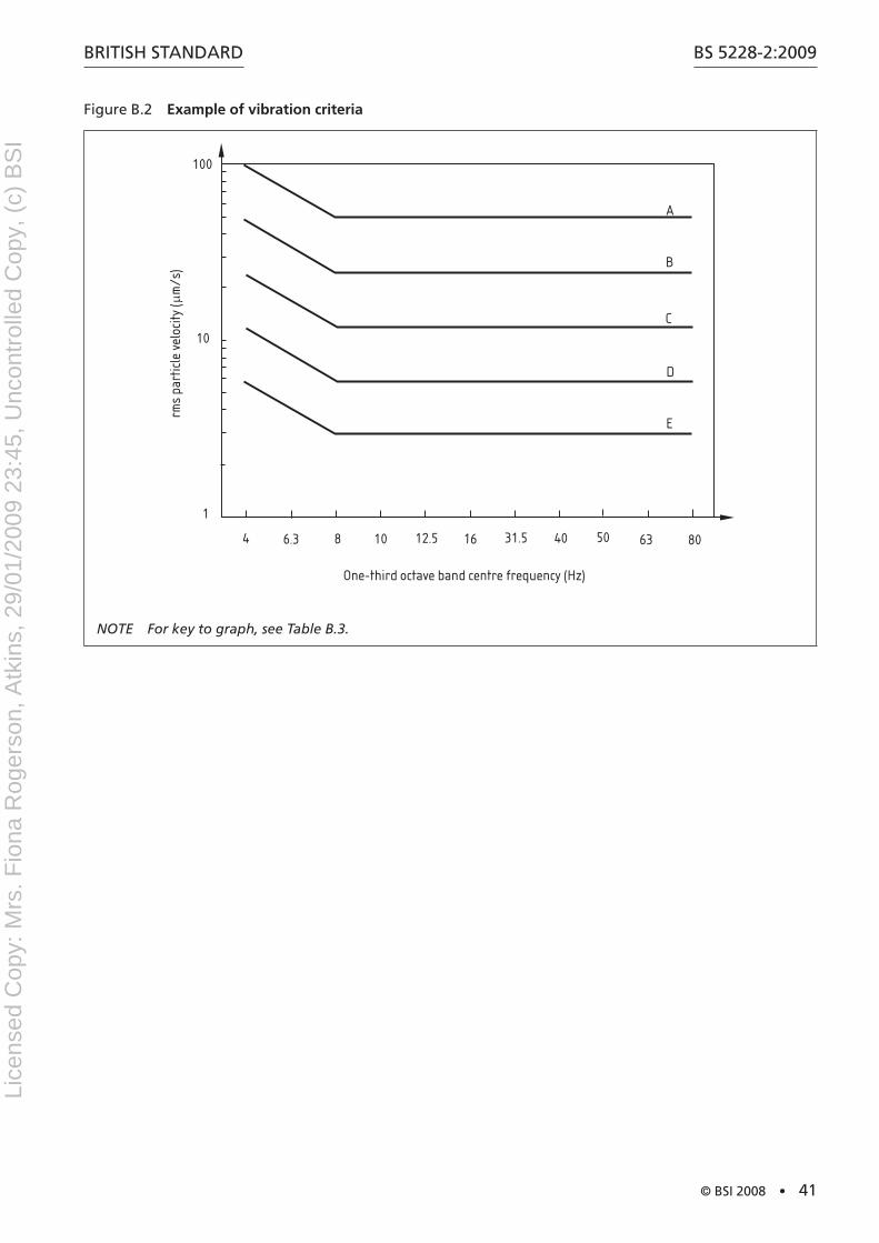
BritiSh Standard
© BSI 2008 • 41
BS 5228-2:2009
Figure B.2 Example of vibration criteria
A
1
10
100
B
C
D
E
4 6.3 8 10 12.5 16 31.5 40 50 63 80
One-third octave band centre frequency (Hz)
rms
part
icle
vel
ocity
( m
/s)
µ
NOTE For key to graph, see Table B.3.
Lice
nsed
Cop
y: M
rs. F
iona
Rog
erso
n, A
tkin
s, 2
9/01
/200
9 23
:45,
Unc
ontr
olle
d C
opy,
(c)
BS
I
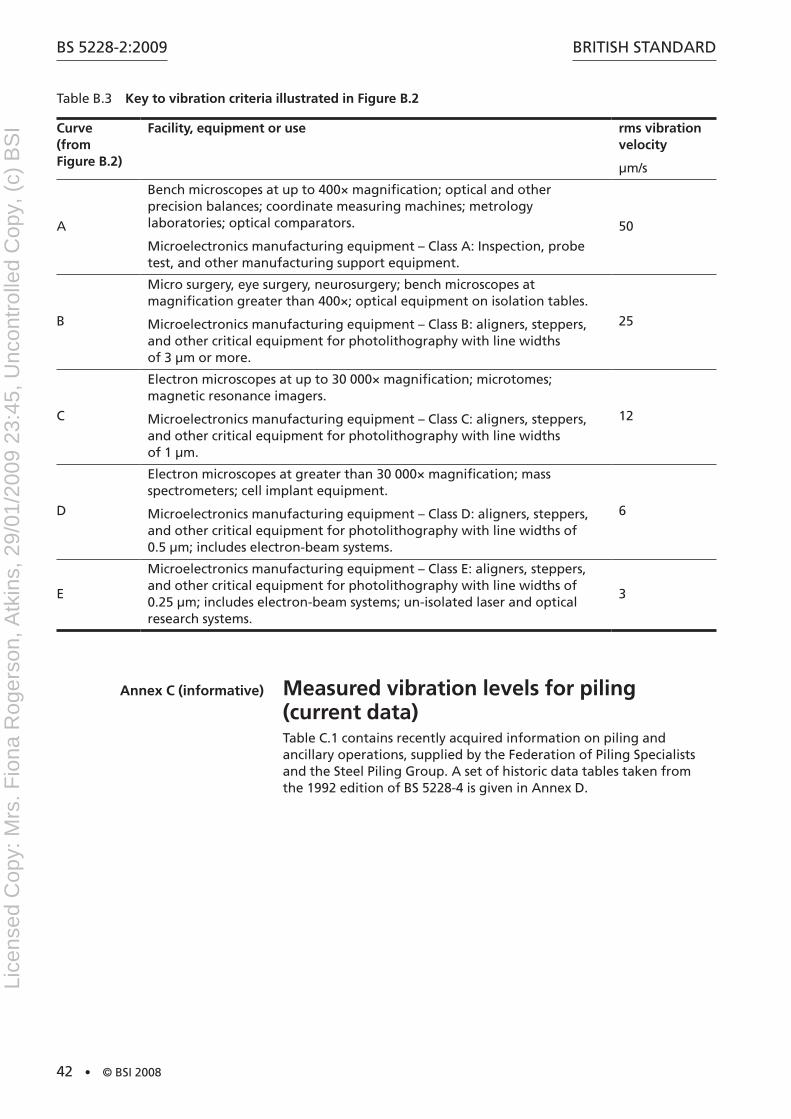
BS 5228-2:2009
42 • © BSI 2008
BritiSh Standard
table B.3 Key to vibration criteria illustrated in Figure B.2
Curve (from Figure B.2)
Facility, equipment or use rms vibration velocity
µm/s
a
Bench microscopes at up to 400× magnification; optical and other precision balances; coordinate measuring machines; metrology laboratories; optical comparators.
Microelectronics manufacturing equipment – Class a: inspection, probe test, and other manufacturing support equipment.
50
B
Micro surgery, eye surgery, neurosurgery; bench microscopes at magnification greater than 400×; optical equipment on isolation tables.
Microelectronics manufacturing equipment – Class B: aligners, steppers, and other critical equipment for photolithography with line widths of 3 µm or more.
25
C
Electron microscopes at up to 30 000× magnification; microtomes; magnetic resonance imagers.
Microelectronics manufacturing equipment – Class C: aligners, steppers, and other critical equipment for photolithography with line widths of 1 µm.
12
d
Electron microscopes at greater than 30 000× magnification; mass spectrometers; cell implant equipment.
Microelectronics manufacturing equipment – Class d: aligners, steppers, and other critical equipment for photolithography with line widths of 0.5 µm; includes electron-beam systems.
6
E
Microelectronics manufacturing equipment – Class E: aligners, steppers, and other critical equipment for photolithography with line widths of 0.25 µm; includes electron-beam systems; un-isolated laser and optical research systems.
3
Annex C (informative) Measured vibration levels for piling (current data)table C.1 contains recently acquired information on piling and ancillary operations, supplied by the Federation of Piling Specialists and the Steel Piling Group. a set of historic data tables taken from the 1992 edition of BS 5228-4 is given in annex d.
Lice
nsed
Cop
y: M
rs. F
iona
Rog
erso
n, A
tkin
s, 2
9/01
/200
9 23
:45,
Unc
ontr
olle
d C
opy,
(c)
BS
I
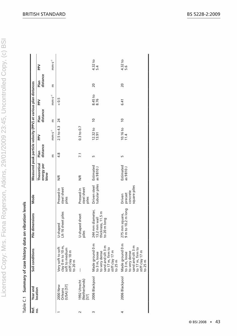
BritiSh Standard
© BSI 2008 • 43
BS 5228-2:2009
tab
le C
.1
Sum
mar
y o
f ca
se h
isto
ry d
ata
on
vib
rati
on
leve
ls
Ref
. n
o.
Year
an
d
loca
tio
nSo
il co
nd
itio
ns
Pile
dim
ensi
on
sM
od
eM
easu
red
pea
k p
arti
cle
velo
city
(PP
V)
at v
ario
us
pla
n d
ista
nce
s
Theo
reti
cal
ener
gy
per
b
low
Plan
d
ista
nce
PPV
Plan
d
ista
nce
PPV
Plan
d
ista
nce
PPV
mm
m·s
−1
mm
m·s
−1
mm
m·s
−1
120
00 n
ew
Orl
ean
s (U
Sa)
[57]
Ver
y so
ft t
o s
oft
cl
ay 0
m t
o 1
0 m
, so
ft t
o m
ediu
m
stif
f cl
ay 1
0 m
to
20
m
U-s
hap
ed
LX-1
6 sh
eet
pile
sPr
esse
d-i
n
stee
l sh
eet
pile
s
n/r
4.8
2.5
to 4
.324
< 0
.5
219
92 U
trec
ht
(net
her
lan
ds)
[5
7]
—U
-sh
aped
sh
eet
pile
sPr
esse
d-i
n
stee
l sh
eet
pile
s
n/r
7.1
0.3
to 0
.7
320
06 B
lack
po
ol
Mad
e g
rou
nd
0 m
to
3 m
, lo
ose
to
ver
y d
ense
sa
nd
an
d s
ilt 3
m
to 1
7 m
, firm
to
st
iff
clay
17
m
to 2
5 m
244
mm
dia
met
er,
13.2
mm
wal
l th
ickn
ess,
11.
5 m
to
20
m lo
ng
dri
ven
ste
el
tub
ula
r p
iles
Esti
mat
ed
as 9
810
J5
12.3
2 to
13
.91
108.
45 t
o
8.76
204.
32 t
o
5.4
420
06 B
lack
po
ol
Mad
e g
rou
nd
0 m
to
3 m
, lo
ose
to
ver
y d
ense
sa
nd
an
d s
ilt 3
m
to 1
7 m
, firm
to
st
iff
clay
17
m
to 2
5 m
275
mm
sq
uar
e,
9 m
to
10.
2 m
lon
gd
rive
n
pre
cast
co
ncr
ete
squ
are
pile
s
Esti
mat
ed
as 9
810
J5
10.1
6 to
11
.410
6.41
204.
32 t
o
5.6
Lice
nsed
Cop
y: M
rs. F
iona
Rog
erso
n, A
tkin
s, 2
9/01
/200
9 23
:45,
Unc
ontr
olle
d C
opy,
(c)
BS
I
BS 5228-2:2009
44 • © BSI 2008
BritiSh Standard
Annex D (informative) Measured vibration levels for piling (historic data)
D.1 Generalthe data given in this annex is largely historical, and is taken unaltered from the tables originally given in BS 5228-4:1992. More recent data is given in annex C.
information on measured vibration levels arising from various forms of piling and kindred operations is summarized in table d.1 to table d.11. data have been compiled from case histories recorded throughout the UK. Examination of the tabulated results will indicate the magnitude of scatter that can be anticipated.
D.2 Symbols and abbreviations used in Table D.1 to Table D.11For the purposes of table d.1 to d.11, the following symbols and abbreviations apply.
ref no. Where the reference is unprefixed, this represents a case history associated with an actual site. Where investigations yielded inadequate (or no) measurements, they have been omitted.
Where the reference number is prefixed by “C”, this represents a case history contributed to the Ciria project rP299. the project report is Ciria technical note 142 [54]. Only case histories reporting measured vibration levels with relevant distances and some geographical information are included in the table. Where the reference number is prefixed by “M”, this represents a case history which does not fall into either of the above two categories.
♦ indicates that some annoyance (human perception of vibration) was reported.§
n/r not recorded or not reported
V Vertical
h horizontal
P Penetration phase for vibroflotation/vibroreplacementC Compaction of stone column phase
PPV Where peak particle velocities are quoted the values will normally be resultant or substitute resultant values (i.e. vectorial sums of the three orthogonal components) unless indicated to the contrary
* indicates that the PPV shown has been calculated from measured displacement and frequency of vibration
+ indicates that the PPV shown has been calculated from measured acceleration and frequency of vibration
91 See explanation in appropriate “remarks” entry
Lice
nsed
Cop
y: M
rs. F
iona
Rog
erso
n, A
tkin
s, 2
9/01
/200
9 23
:45,
Unc
ontr
olle
d C
opy,
(c)
BS
I
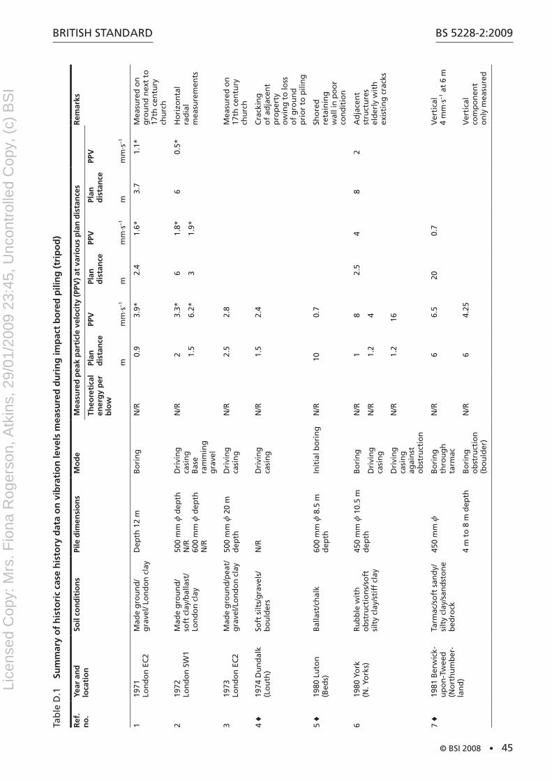
BritiSh Standard
© BSI 2008 • 45
BS 5228-2:2009
tab
le d
.1
Sum
mar
y o
f h
isto
ric
case
his
tory
dat
a o
n v
ibra
tio
n le
vels
mea
sure
d d
uri
ng
imp
act
bo
red
pili
ng
(tr
ipo
d)
Ref
. n
o.
Year
an
d
loca
tio
nSo
il co
nd
itio
ns
Pile
dim
ensi
on
sM
od
eM
easu
red
pea
k p
arti
cle
velo
city
(PP
V)
at v
ario
us
pla
n d
ista
nce
sR
emar
ks
Theo
reti
cal
ener
gy
per
b
low
Plan
d
ista
nce
PPV
Plan
d
ista
nce
PPV
Plan
d
ista
nce
PPV
mm
m·s
−1
mm
m·s
−1
mm
m·s
−1
119
71
Lon
do
n E
C2
Mad
e g
rou
nd
/g
rave
l/ Lo
nd
on
cla
yd
epth
12
mB
ori
ng
n/r
0.9
3.9*
2.4
1.6*
3.7
1.1*
Mea
sure
d o
n
gro
un
d n
ext
to
17th
cen
tury
ch
urc
h
219
72
Lon
do
n S
W1
Mad
e g
rou
nd
/ so
ft c
lay/
bal
last
/ Lo
nd
on
cla
y
500
mm
z d
epth
n
/r
600
mm
z d
epth
n
/r
dri
vin
g
casi
ng
B
ase
ram
min
g
gra
vel
n/r
23.
3*6
1.8*
60.
5*h
ori
zon
tal
rad
ial
mea
sure
men
ts1.
56.
2*3
1.9*
319
73
Lon
do
n E
C2
Mad
e g
rou
nd
/pea
t/
gra
vel/L
on
do
n c
lay
500
mm
z 2
0 m
d
epth
dri
vin
g
casi
ng
n/r
2.5
2.8
Mea
sure
d o
n
17th
cen
tury
ch
urc
h
4 ♦
1974
du
nd
alk
(Lo
uth
)So
ft s
ilts/
gra
vels
/ b
ou
lder
sn
/rd
rivi
ng
ca
sin
gn
/r1.
52.
4C
rack
ing
o
f ad
jace
nt
pro
per
ty
ow
ing
to
loss
o
f g
rou
nd
p
rio
r to
pili
ng
5 ♦
1980
Lu
ton
(B
eds)
Bal
last
/ch
alk
600
mm
z 8
.5 m
d
epth
init
ial b
ori
ng
n/r
100.
7Sh
ore
d
reta
inin
g
wal
l in
po
or
con
dit
ion
619
80 Y
ork
(n
. Yo
rks)
ru
bb
le w
ith
o
bst
ruct
ion
s/so
ft
silt
y cl
ay/s
tiff
cla
y
450
mm
z 1
0.5
m
dep
thB
ori
ng
n/r
18
2.5
48
2a
dja
cen
t st
ruct
ure
s el
der
ly w
ith
ex
isti
ng
cra
cks
dri
vin
g
casi
ng
n/r
1.2
4
dri
vin
g
casi
ng
ag
ain
st
ob
stru
ctio
n
n/r
1.2
16
7 ♦
1981
Ber
wic
k-
up
on
-tw
eed
(n
ort
hu
mb
er-
lan
d)
tarm
ac/s
oft
san
dy/
si
lty
clay
/san
dst
on
e b
edro
ck
450
mm
zB
ori
ng
th
rou
gh
ta
rmac
n/r
66.
520
0.7
Ver
tica
l 4
mm
·s−
1 at
6 m
4 m
to
8 m
dep
thB
ori
ng
o
bst
ruct
ion
(b
ou
lder
)
n/r
64.
25V
erti
cal
com
po
nen
t o
nly
mea
sure
d
Lice
nsed
Cop
y: M
rs. F
iona
Rog
erso
n, A
tkin
s, 2
9/01
/200
9 23
:45,
Unc
ontr
olle
d C
opy,
(c)
BS
I
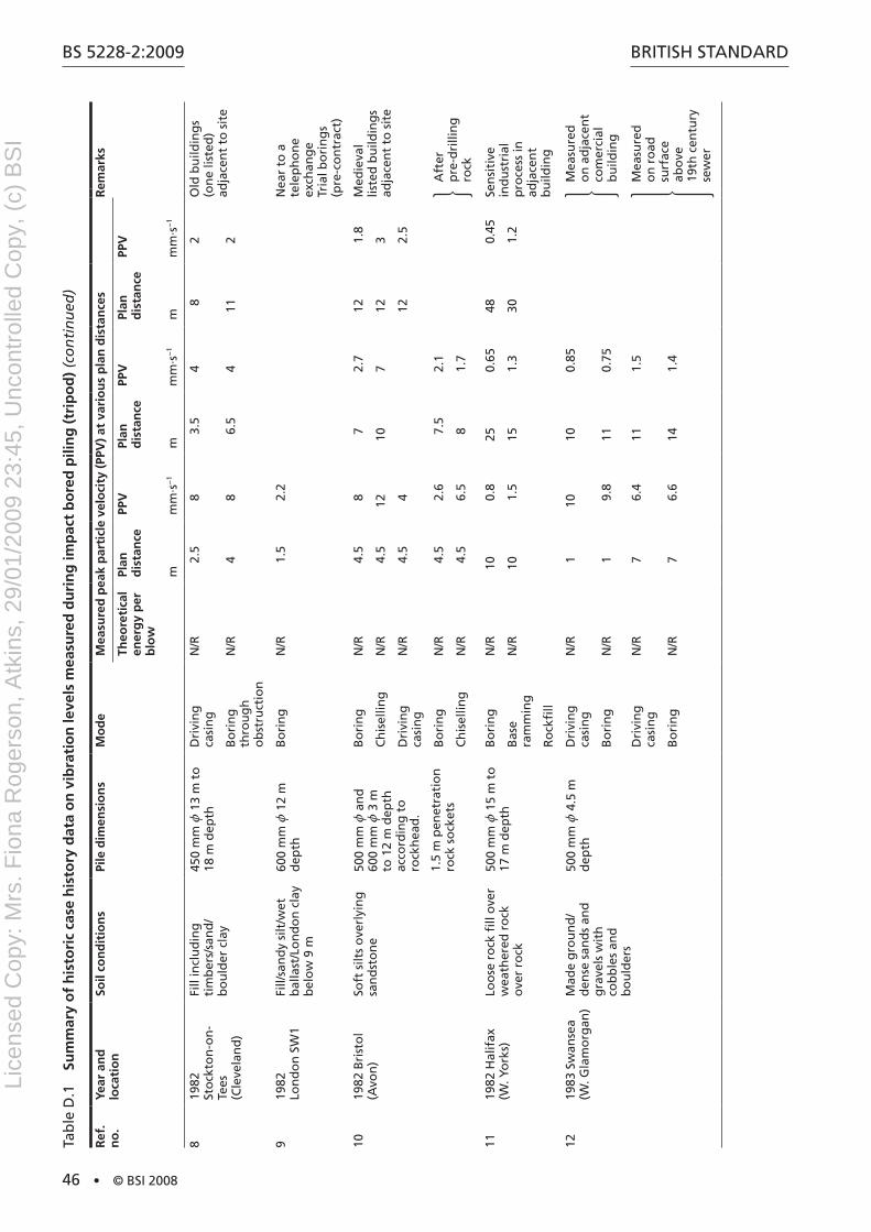
BS 5228-2:2009
46 • © BSI 2008
BritiSh Standard
Ref
. n
o.
Year
an
d
loca
tio
nSo
il co
nd
itio
ns
Pile
dim
ensi
on
sM
od
eM
easu
red
pea
k p
arti
cle
velo
city
(PP
V)
at v
ario
us
pla
n d
ista
nce
sR
emar
ks
Theo
reti
cal
ener
gy
per
b
low
Plan
d
ista
nce
PPV
Plan
d
ista
nce
PPV
Plan
d
ista
nce
PPV
mm
m·s
−1
mm
m·s
−1
mm
m·s
−1
819
82
Sto
ckto
n-o
n-
tees
(C
leve
lan
d)
Fill
incl
ud
ing
ti
mb
ers/
san
d/
bo
uld
er c
lay
450
mm
z 1
3 m
to
18
m d
epth
dri
vin
g
casi
ng
n/r
2.5
83.
54
82
Old
bu
ildin
gs
(on
e lis
ted
) ad
jace
nt
to s
ite
Bo
rin
g
thro
ug
h
ob
stru
ctio
n
n/r
48
6.5
411
2
919
82
Lon
do
n S
W1
Fill/
san
dy
silt
/wet
b
alla
st/L
on
do
n c
lay
bel
ow
9 m
600
mm
z 1
2 m
d
epth
Bo
rin
gn
/r1.
52.
2n
ear
to a
te
lep
ho
ne
exch
ang
e tr
ial b
ori
ng
s (p
re-c
on
trac
t)
1019
82 B
rist
ol
(avo
n)
Soft
silt
s o
verl
yin
g
san
dst
on
e50
0 m
m z
an
d
600
mm
z 3
m
to 1
2 m
dep
th
acco
rdin
g t
o
rock
hea
d.
1.5
m p
enet
rati
on
ro
ck s
ock
ets
Bo
rin
gn
/r4.
58
72.
712
1.8
Med
ieva
l lis
ted
bu
ildin
gs
adja
cen
t to
sit
eC
his
ellin
gn
/r4.
512
107
123
dri
vin
g
casi
ng
n/r
4.5
412
2.5
Bo
rin
gn
/r4.
52.
67.
52.
1a
fter
p
re-d
rilli
ng
ro
ckC
his
ellin
gn
/r4.
56.
58
1.7
1119
82 h
alif
ax
(W. Y
ork
s)Lo
ose
ro
ck fi
ll o
ver
wea
ther
ed r
ock
o
ver
rock
500
mm
z 1
5 m
to
17
m d
epth
Bo
rin
gn
/r10
0.8
250.
6548
0.45
Sen
siti
ve
ind
ust
rial
p
roce
ss in
ad
jace
nt
bu
ildin
g
Bas
e ra
mm
ing
n/r
101.
515
1.3
301.
2
ro
ckfi
ll
1219
83 S
wan
sea
(W. G
lam
org
an)
Mad
e g
rou
nd
/d
ense
san
ds
and
g
rave
ls w
ith
co
bb
les
and
b
ou
lder
s
500
mm
z 4
.5 m
d
epth
dri
vin
g
casi
ng
n/r
110
100.
85M
easu
red
o
n a
dja
cen
t co
mer
cial
b
uild
ing
Bo
rin
gn
/r1
9.8
110.
75
dri
vin
g
casi
ng
n/r
76.
411
1.5
Mea
sure
d
on
ro
ad
surf
ace
abo
ve
19th
cen
tury
se
wer
Bo
rin
gn
/r7
6.6
141.
4
tab
le d
.1
Sum
mar
y o
f h
isto
ric
case
his
tory
dat
a o
n v
ibra
tio
n le
vels
mea
sure
d d
uri
ng
imp
act
bo
red
pili
ng
(tr
ipo
d)
(co
nti
nu
ed)
Lice
nsed
Cop
y: M
rs. F
iona
Rog
erso
n, A
tkin
s, 2
9/01
/200
9 23
:45,
Unc
ontr
olle
d C
opy,
(c)
BS
I
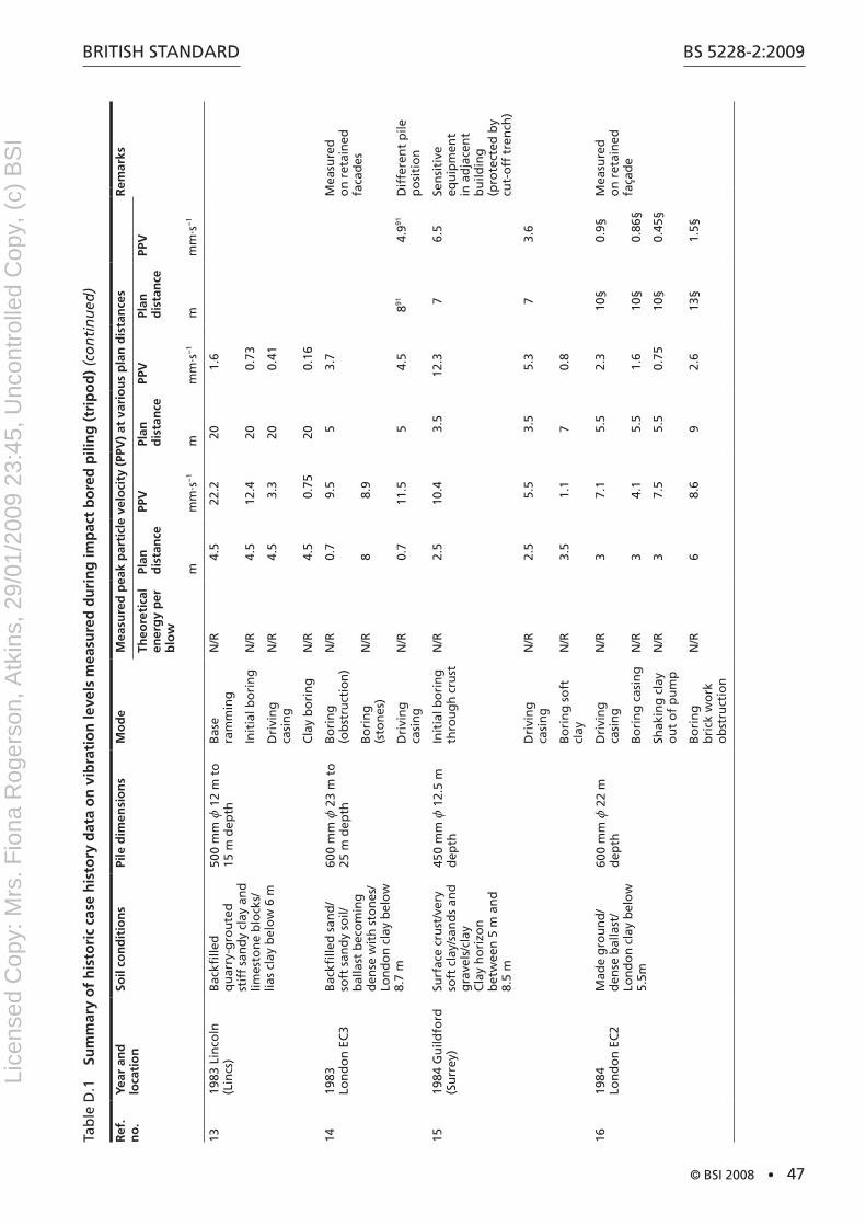
BritiSh Standard
© BSI 2008 • 47
BS 5228-2:2009
Ref
. n
o.
Year
an
d
loca
tio
nSo
il co
nd
itio
ns
Pile
dim
ensi
on
sM
od
eM
easu
red
pea
k p
arti
cle
velo
city
(PP
V)
at v
ario
us
pla
n d
ista
nce
sR
emar
ks
Theo
reti
cal
ener
gy
per
b
low
Plan
d
ista
nce
PPV
Plan
d
ista
nce
PPV
Plan
d
ista
nce
PPV
mm
m·s
−1
mm
m·s
−1
mm
m·s
−1
1319
83 L
inco
ln
(Lin
cs)
Bac
kfille
d
qu
arry
-gro
ute
d
stif
f sa
nd
y cl
ay a
nd
lim
esto
ne
blo
cks/
lias
clay
bel
ow
6 m
500
mm
z 1
2 m
to
15
m d
epth
Bas
e ra
mm
ing
n/r
4.5
22.2
201.
6
init
ial b
ori
ng
n/r
4.5
12.4
200.
73
dri
vin
g
casi
ng
n/r
4.5
3.3
200.
41
Cla
y b
ori
ng
n/r
4.5
0.75
200.
16
1419
83
Lon
do
n E
C3
Bac
kfille
d s
and
/so
ft s
and
y so
il/b
alla
st b
eco
min
g
den
se w
ith
sto
nes
/Lo
nd
on
cla
y b
elo
w
8.7
m
600
mm
z 2
3 m
to
25
m d
epth
Bo
rin
g
(ob
stru
ctio
n)
n/r
0.7
9.5
53.
7M
easu
red
o
n r
etai
ned
fa
cad
esB
ori
ng
(s
ton
es)
n/r
88.
9
dri
vin
g
casi
ng
n/r
0.7
11.5
54.
5891
4.991
dif
fere
nt
pile
p
osi
tio
n
1519
84 G
uild
ford
(S
urr
ey)
Surf
ace
cru
st/v
ery
soft
cla
y/sa
nd
s an
d
gra
vels
/cla
y
Cla
y h
ori
zon
b
etw
een
5 m
an
d
8.5
m
450
mm
z 1
2.5
m
dep
thin
itia
l bo
rin
g
thro
ug
h c
rust
n/r
2.5
10.4
3.5
12.3
76.
5Se
nsi
tive
eq
uip
men
t in
ad
jace
nt
bu
ildin
g
(pro
tect
ed b
y cu
t-o
ff t
ren
ch)
dri
vin
g
casi
ng
n/r
2.5
5.5
3.5
5.3
73.
6
Bo
rin
g s
oft
cl
ayn
/r3.
51.
17
0.8
1619
84
Lon
do
n E
C2
Mad
e g
rou
nd
/d
ense
bal
last
/Lo
nd
on
cla
y b
elo
w
5.5m
600
mm
z 2
2 m
d
epth
dri
vin
g
casi
ng
n/r
37.
15.
52.
310
§0.
9§M
easu
red
o
n r
etai
ned
fa
çad
eB
ori
ng
cas
ing
n/r
34.
15.
51.
610
§0.
86§
Shak
ing
cla
y o
ut
of
pu
mp
n
/r3
7.5
5.5
0.75
10§
0.45
§
Bo
rin
g
bri
ck w
ork
o
bst
ruct
ion
n/r
68.
69
2.6
13§
1.5§
tab
le d
.1
Sum
mar
y o
f h
isto
ric
case
his
tory
dat
a o
n v
ibra
tio
n le
vels
mea
sure
d d
uri
ng
imp
act
bo
red
pili
ng
(tr
ipo
d)
(co
nti
nu
ed)
Lice
nsed
Cop
y: M
rs. F
iona
Rog
erso
n, A
tkin
s, 2
9/01
/200
9 23
:45,
Unc
ontr
olle
d C
opy,
(c)
BS
I
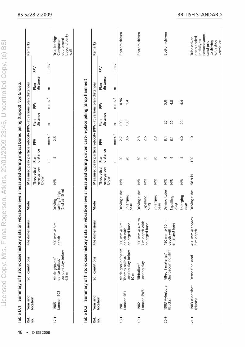
BS 5228-2:2009
48 • © BSI 2008
BritiSh Standard
Ref
. n
o.
Year
an
d
loca
tio
nSo
il co
nd
itio
ns
Pile
dim
ensi
on
sM
od
eM
easu
red
pea
k p
arti
cle
velo
city
(PP
V)
at v
ario
us
pla
n d
ista
nce
sR
emar
ks
Theo
reti
cal
ener
gy
per
b
low
Plan
d
ista
nce
PPV
Plan
d
ista
nce
PPV
Plan
d
ista
nce
PPV
mm
m·s
−1
mm
m·s
−1
mm
m·s
−1
17 ♦
1985
Lo
nd
on
EC
3M
ade
gro
un
d/
den
se b
alla
st/
Lon
do
n c
lay
bel
ow
6.
5 m
500
mm
z 8
m
dep
thd
rivi
ng
ca
sin
g 2
rig
s (2
nd
at
10 m
)
n/r
42.
5tr
ial b
ori
ng
s C
om
pu
ter
equ
ipm
ent
bey
on
d p
arty
w
all
tab
le d
.2
Sum
mar
y o
f h
isto
ric
case
his
tory
dat
a o
n v
ibra
tio
n le
vels
mea
sure
d d
uri
ng
dri
ven
cas
t-in
-pla
ce p
ilin
g (
dro
p h
amm
er)
Ref
. n
o.
Year
an
d
loca
tio
nSo
il co
nd
itio
ns
Pile
dim
ensi
on
sM
od
eM
easu
red
pea
k p
arti
cle
velo
city
(PP
V)
at v
ario
us
pla
n d
ista
nce
sR
emar
ks
Theo
reti
cal
ener
gy
per
b
low
Plan
d
ista
nce
PPV
Plan
d
ista
nce
PPV
Plan
d
ista
nce
PPV
mm
m·s
−1
mm
m·s
−1
mm
m·s
−1
18 ♦
1981
Lo
nd
on
SE1
Mad
e g
rou
nd
/pea
t/
tham
es b
alla
st/
Lon
do
n c
lay
bel
ow
10
m
500
mm
z 6
m
dep
th w
ith
en
larg
ed b
ase
dri
vin
g t
ub
en
/r20
2.7
100
0.96
Bo
tto
m-d
rive
n
Enla
rgin
g
bas
e20
3.6
100
1.4
19 ♦
1982
Lo
nd
on
SW
6Fi
ll/b
alla
st/
Lon
do
n c
lay
500
mm
z 4
m t
o
7 m
dep
th w
ith
en
larg
ed b
ase
dri
vin
g t
ub
en
/r30
2.3
Bo
tto
m-d
rive
n
Exp
ellin
g
plu
gn
/r30
2.6
Enla
rgin
g
bas
en
/r30
2.3
20 ♦
1983
ayl
esb
ury
(B
uck
s)Fi
ll/so
ft m
ater
ial/
clay
bec
om
ing
sti
ff45
0 m
m z
10
m
dep
th w
ith
en
larg
ed b
ase
dri
vin
g t
ub
en
/r4
8.4
205.
0B
ott
om
-dri
ven
Exp
ellin
g
plu
gn
/r4
6.1
204.
8
Enla
rgin
g
bas
en
/r4
4.0
204.
4
21 ♦
1983
ald
ersh
ot
(han
ts)
den
se fi
ne
san
d45
0 m
m z
ap
pro
x 6
m d
epth
dri
vin
g t
ub
e58
.9 k
J12
01.
0tu
be
dri
ven
o
pen
en
ded
in
itia
lly t
o
rem
ove
so
me
san
d p
rio
r to
dri
vin
g
wit
h s
ho
e to
p-d
rive
n
tab
le d
.1
Sum
mar
y o
f h
isto
ric
case
his
tory
dat
a o
n v
ibra
tio
n le
vels
mea
sure
d d
uri
ng
imp
act
bo
red
pili
ng
(tr
ipo
d)
(co
nti
nu
ed)
Lice
nsed
Cop
y: M
rs. F
iona
Rog
erso
n, A
tkin
s, 2
9/01
/200
9 23
:45,
Unc
ontr
olle
d C
opy,
(c)
BS
I

BritiSh Standard
© BSI 2008 • 49
BS 5228-2:2009
Ref
. n
o.
Year
an
d
loca
tio
nSo
il co
nd
itio
ns
Pile
dim
ensi
on
sM
od
eM
easu
red
pea
k p
arti
cle
velo
city
(PP
V)
at v
ario
us
pla
n d
ista
nce
sR
emar
ks
Theo
reti
cal
ener
gy
per
b
low
Plan
d
ista
nce
PPV
Plan
d
ista
nce
PPV
Plan
d
ista
nce
PPV
mm
m·s
−1
mm
m·s
−1
mm
m·s
−1
22 ♦
1983
ho
rsh
am
(W. S
uss
ex)
Peat
y, s
ilty
allu
via
ove
r sh
ale
and
sa
nd
sto
ne
350
mm
z 7
.5 m
to
8
m d
epth
dri
vin
g t
ub
e38
.8 k
J21
2.9
282.
735
2.4
top
-dri
ven
Extr
acti
ng
tu
be
213.
228
3.9
353.
1
23 ♦
1983
red
hill
(S
urr
ey)
den
se fi
ne
san
d
wit
h ir
on
sto
ne
ban
ds
450
mm
z 8
m
dep
th (
max
) (6
m
aver
age)
dri
vin
g t
ub
en
/r22
.53.
143
1.1
Bo
tto
m-d
rive
n,
com
pu
ter
etc.
in
ad
jace
nt
bu
ildin
g
Exp
ellin
g
plu
g43
1.25
24 ♦
1984
W
eym
ou
th
(do
rset
)
2 m
to
3 m
th
ick
cru
st o
f sa
nd
s an
d g
rave
l ove
r es
tuar
ial s
ilty
clay
s b
eco
min
g fi
rmer
at
gre
ater
dep
th
350
mm
z 1
5 m
d
epth
So
me
wit
h
enla
rged
bas
e
dri
vin
g t
ub
e o
pen
en
ded
47.1
kJ
8.5
6.1
133.
6to
p-d
rive
n
dri
vin
g t
ub
e w
ith
sh
oe
47.1
kJ
8.5
8.3
134.
4
Extr
acti
ng
tu
be
8.5
2.9
252.
1
Enla
rgin
g
bas
e25
2.2
25 ♦
1984
C
amb
rid
ge
(Cam
bs.
)
4.75
m t
o 6
.75
m
loo
se fi
ll o
ver
gau
lt
clay
bec
om
ing
st
iffe
r w
ith
dep
th
350
mm
z 1
0 m
to
11
m d
epth
wit
h
enla
rged
bas
e
dri
vin
g t
ub
e47
.1 k
J13
5.6
223.
134
2.6
top
-dri
ven
, se
nsi
tive
eq
uip
men
t in
ad
jace
nt
bu
ildin
g
Enla
rgin
g
bas
e13
4.9
221.
934
1.1
Extr
acti
ng
tu
be
134.
622
2.5
341.
6
26 ♦
1984
Lo
nd
on
E14
Fill
ove
r th
ames
b
alla
st40
0 m
m z
5 m
d
epth
dri
vin
g t
ub
e47
.1 k
J5.
510
.712
5.9
213.
4to
p-d
rive
n,
clo
se t
o m
ain
se
rvic
e p
ipes
Extr
acti
ng
tu
be
5.5
3.2
122.
821
2.0
27 ♦
1984
isle
wo
rth
(G
reat
er
Lon
do
n)
Cla
yey
fill/
Lon
do
n
clay
350
mm
z 1
0 m
to
12
m d
epth
So
me
wit
h
enla
rged
bas
e
dri
vin
g t
ub
e23
.5 k
J30
1.05
350.
9540
0.66
top
-dri
ven
, m
easu
red
on
su
spen
ded
fl
oo
r in
a
com
pu
ter
roo
m
Enla
rgin
g
bas
e35
0.76
Extr
acti
ng
tu
be
300.
55
tab
le d
.2
Sum
mar
y o
f h
isto
ric
case
his
tory
dat
a o
n v
ibra
tio
n le
vels
mea
sure
d d
uri
ng
dri
ven
cas
t-in
-pla
ce p
ilin
g (
dro
p h
amm
er)
(co
nti
nu
ed)
Lice
nsed
Cop
y: M
rs. F
iona
Rog
erso
n, A
tkin
s, 2
9/01
/200
9 23
:45,
Unc
ontr
olle
d C
opy,
(c)
BS
I
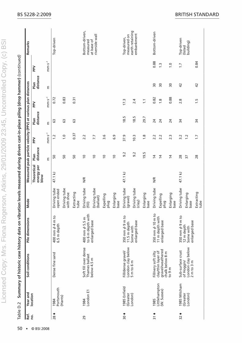
BS 5228-2:2009
50 • © BSI 2008
BritiSh Standard
Ref
. n
o.
Year
an
d
loca
tio
nSo
il co
nd
itio
ns
Pile
dim
ensi
on
sM
od
eM
easu
red
pea
k p
arti
cle
velo
city
(PP
V)
at v
ario
us
pla
n d
ista
nce
sR
emar
ks
Theo
reti
cal
ener
gy
per
b
low
Plan
d
ista
nce
PPV
Plan
d
ista
nce
PPV
Plan
d
ista
nce
PPV
mm
m·s
−1
mm
m·s
−1
mm
m·s
−1
28 ♦
1984
Po
rtsm
ou
th
(han
ts)
den
se fi
ne
san
d40
0 m
m z
4 m
to
6.
5 m
dep
thd
rivi
ng
tu
be
op
en e
nd
ed47
.1 k
J50
1.2
630.
72to
p-d
rive
n
dri
vin
g t
ub
e w
ith
sh
oe
501.
063
0.83
Extr
acti
ng
tu
be
500.
3763
0.31
2919
84
Lon
do
n E
1So
ft fi
ll o
ver
den
se
tham
es b
alla
st
bel
ow
4.5
m
400
mm
z 5
.5 m
to
6 m
dep
th w
ith
en
larg
ed b
ase
dri
vin
g t
ub
e (fi
ll)n
/r10
2.2
Bo
tto
m-d
rive
n,
mea
sure
d
at b
ase
of
rive
rsid
e w
all
dri
vin
g t
ub
e (b
alla
st)
107.
7
Exp
ellin
g
plu
g10
3.6
Enla
rgin
g
bas
e10
6.9
30 ♦
1985
En
fiel
d
(Gre
ater
Lo
nd
on
)
Fill/
den
se g
rave
l/Lo
nd
on
cla
y b
elo
w
5 m
to
6 m
350
mm
z 9
m t
o
11.5
m d
epth
So
me
wit
h
enla
rged
bas
e
dri
vin
g t
ub
e (g
rave
l)47
.1 k
J9.
237
.918
.517
.3to
p-d
rive
n,
mea
sure
d o
n
eart
h r
etai
nin
g
emb
ankm
ent
dri
vin
g t
ub
e (c
lay)
9.2
10.3
18.5
2.4
Enla
rgin
g
bas
e19
.51.
829
.71.
1
31 ♦
1985
Li
ttle
ham
pto
n
(W. S
uss
ex)
Fill/
very
so
ft s
ilty
clay
/th
in la
yer
of
gra
vel/w
eath
ered
ch
alk
bel
ow
8 m
to
9 m
350
mm
z 1
0 m
to
11
m d
epth
wit
h
enla
rged
bas
e
dri
vin
g t
ub
en
/r14
2.2
240.
8230
0.88
Bo
tto
m-d
rive
n
Exp
ellin
g
plu
g14
2.2
241.
830
1.3
Enla
rgin
g
bas
e14
2.3
240.
8830
1.0
32 ♦
1985
Mit
cham
(G
reat
er
Lon
do
n)
Sub
-su
rfac
e cr
ust
o
f h
og
gin
/ Lo
nd
on
cla
y b
elo
w
2 m
to
3 m
350
mm
z 9
m t
o
12 m
dep
th
Som
e w
ith
en
larg
ed b
ase
dri
vin
g t
ub
e47
.1 k
J28
3.2
342.
842
1.7
top
-dri
ven
(l
iste
d
bu
ildin
g)
Enla
rgin
g
bas
e37
1.2
Extr
acti
ng
tu
be
281.
734
1.5
420.
84
tab
le d
.2
Sum
mar
y o
f h
isto
ric
case
his
tory
dat
a o
n v
ibra
tio
n le
vels
mea
sure
d d
uri
ng
dri
ven
cas
t-in
-pla
ce p
ilin
g (
dro
p h
amm
er)
(co
nti
nu
ed)
Lice
nsed
Cop
y: M
rs. F
iona
Rog
erso
n, A
tkin
s, 2
9/01
/200
9 23
:45,
Unc
ontr
olle
d C
opy,
(c)
BS
I

BritiSh Standard
© BSI 2008 • 51
BS 5228-2:2009
Ref
. n
o.
Year
an
d
loca
tio
nSo
il co
nd
itio
ns
Pile
dim
ensi
on
sM
od
eM
easu
red
pea
k p
arti
cle
velo
city
(PP
V)
at v
ario
us
pla
n d
ista
nce
sR
emar
ks
Theo
reti
cal
ener
gy
per
b
low
Plan
d
ista
nce
PPV
Plan
d
ista
nce
PPV
Plan
d
ista
nce
PPV
mm
m·s
−1
mm
m·s
−1
mm
m·s
−1
33 ♦
1985
Uxb
rid
ge
(Gre
ater
Lo
nd
on
)
Fill
(in
clu
din
g
po
cket
s o
f g
rave
l)
Lon
do
n c
lay
bel
ow
3
m
350
mm
z 5
m t
o
12.5
m d
epth
So
me
wit
h
enla
rged
bas
e
dri
vin
g t
ub
e23
.5 k
J to
35
.3 k
J10
4.2
(V)
142.
2 (V
)to
p-d
rive
n
dri
vin
g
tub
e af
ter
pre
bo
rin
g
5.5
3.3
92.
013
1.4
Enla
rgin
g
bas
e5.
52.
89
3.5
132.
8
Extr
acti
ng
tu
be
5.5
5.9
93.
413
2.9
tab
le d
.3
Sum
mar
y o
f h
isto
ric
case
his
tory
dat
a o
n v
ibra
tio
n le
vels
mea
sure
d d
uri
ng
dyn
amic
co
nso
lidat
ion
Ref
. n
o.
Year
an
d
loca
tio
nSo
il co
nd
itio
ns
Tam
pin
g w
eig
ht
Mo
de
Mea
sure
d p
eak
par
ticl
e ve
loci
ty (
PPV
) at
var
iou
s p
lan
dis
tan
ces
Rem
arks
Theo
reti
cal
ener
gy
per
b
low
Plan
d
ista
nce
PPV
Plan
d
ista
nce
PPV
Plan
d
ista
nce
PPV
tm
mm
·s−
1m
mm
·s−
1m
mm
·s−
1
3419
73 C
orb
y (n
ort
han
ts.)
9Pa
ss 1
Up
to
1.
59 M
J25
3.0*
225
0.16
*
Pass
2U
p t
o
1.59
MJ
254.
7*12
00.
33*
3519
73 B
elfa
st
(an
trim
)C
lay
fill
101.
47 M
J8
4226
3.6
441.
75d
rop
pin
g o
nto
vi
rgin
gro
un
d
1.96
MJ
1412
253.
249
1.35
dro
pp
ing
on
to
fill
981
kJ14
1025
2.9
491.
4
3619
74 t
eess
ide
(Cle
vela
nd
)h
ydra
ulic
fill
of
clea
n s
and
wit
h
som
e p
ebb
les
17Pa
ss 1
2.50
MJ
524
012
5320
15.5
Pass
22.
50 M
J5
177
1267
2020
.3
37 ♦
1975
C
ante
rbu
ry
(Ken
t)
San
d fi
ll co
nta
inin
g
mu
ch fi
ne
silt
n/r
20 m
dro
p12
16.5
205.
832
2.7
15 m
dro
p10
20.5
206
323.
3
10 m
dro
p12
15.5
204.
528
2.2
tab
le d
.2
Sum
mar
y o
f h
isto
ric
case
his
tory
dat
a o
n v
ibra
tio
n le
vels
mea
sure
d d
uri
ng
dri
ven
cas
t-in
-pla
ce p
ilin
g (
dro
p h
amm
er)
(co
nti
nu
ed)
Lice
nsed
Cop
y: M
rs. F
iona
Rog
erso
n, A
tkin
s, 2
9/01
/200
9 23
:45,
Unc
ontr
olle
d C
opy,
(c)
BS
I
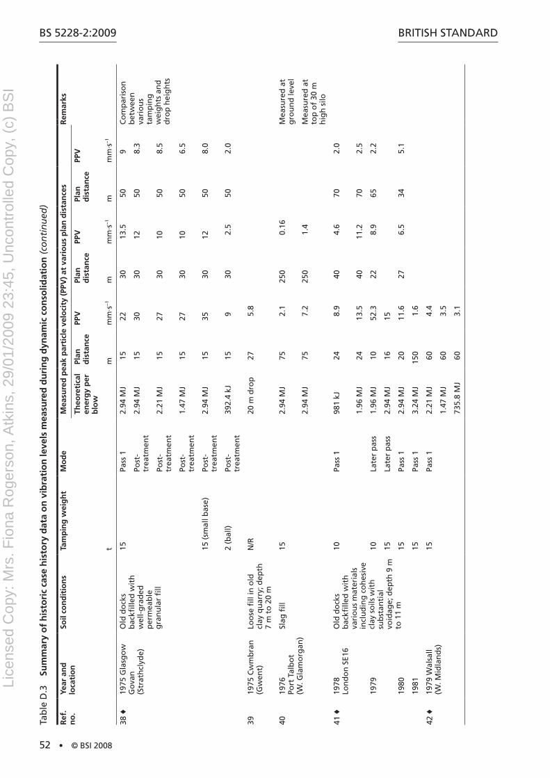
BS 5228-2:2009
52 • © BSI 2008
BritiSh Standard
Ref
. n
o.
Year
an
d
loca
tio
nSo
il co
nd
itio
ns
Tam
pin
g w
eig
ht
Mo
de
Mea
sure
d p
eak
par
ticl
e ve
loci
ty (
PPV
) at
var
iou
s p
lan
dis
tan
ces
Rem
arks
Theo
reti
cal
ener
gy
per
b
low
Plan
d
ista
nce
PPV
Plan
d
ista
nce
PPV
Plan
d
ista
nce
PPV
tm
mm
·s−
1m
mm
·s−
1m
mm
·s−
1
38 ♦
1975
Gla
sgo
w
Go
van
(S
trat
hcl
yde)
Old
do
cks
bac
kfille
d w
ith
w
ell-
gra
ded
p
erm
eab
le
gra
nu
lar
fill
15Pa
ss 1
2.94
MJ
1522
3013
.550
9C
om
par
iso
n
bet
wee
n
vari
ou
s ta
mp
ing
w
eig
hts
an
d
dro
p h
eig
hts
Post
- tr
eatm
ent
2.94
MJ
1530
3012
508.
3
Post
- tr
eatm
ent
2.21
MJ
1527
3010
508.
5
Post
- tr
eatm
ent
1.47
MJ
1527
3010
506.
5
15 (
smal
l bas
e)Po
st-
trea
tmen
t2.
94 M
J15
3530
1250
8.0
2 (b
all)
Post
- tr
eatm
ent
392.
4 kJ
159
302.
550
2.0
3919
75 C
wm
bra
n
(Gw
ent)
Loo
se fi
ll in
old
cl
ay q
uar
ry; d
epth
7
m t
o 2
0 m
n/r
20 m
dro
p27
5.8
4019
76
Port
tal
bo
t (W
. Gla
mo
rgan
)
Slag
fill
152.
94 M
J75
2.1
250
0.16
Mea
sure
d a
t g
rou
nd
leve
l
2.94
MJ
757.
225
01.
4M
easu
red
at
top
of
30 m
h
igh
silo
41 ♦
1978
Lo
nd
on
SE1
6O
ld d
ock
s b
ackfi
lled
wit
h
vari
ou
s m
ater
ials
in
clu
din
g c
oh
esiv
e cl
ay s
oils
wit
h
sub
stan
tial
vo
idag
e; d
epth
9 m
to
11
m
10Pa
ss 1
981
kJ24
8.9
404.
670
2.0
1.96
MJ
2413
.540
11.2
702.
5
1979
10La
ter
pas
s1.
96 M
J10
52.3
228.
965
2.2
15La
ter
pas
s2.
94 M
J16
15
1980
15Pa
ss 1
2.94
MJ
2011
.627
6.5
345.
1
1981
15Pa
ss 1
3.24
MJ
150
1.6
42 ♦
1979
Wal
sall
(W. M
idla
nd
s)15
Pass
12.
21 M
J60
4.4
1.47
MJ
603.
5
735.
8 M
J60
3.1
tab
le d
.3
Sum
mar
y o
f h
isto
ric
case
his
tory
dat
a o
n v
ibra
tio
n le
vels
mea
sure
d d
uri
ng
dyn
amic
co
nso
lidat
ion
(co
nti
nu
ed)
Lice
nsed
Cop
y: M
rs. F
iona
Rog
erso
n, A
tkin
s, 2
9/01
/200
9 23
:45,
Unc
ontr
olle
d C
opy,
(c)
BS
I
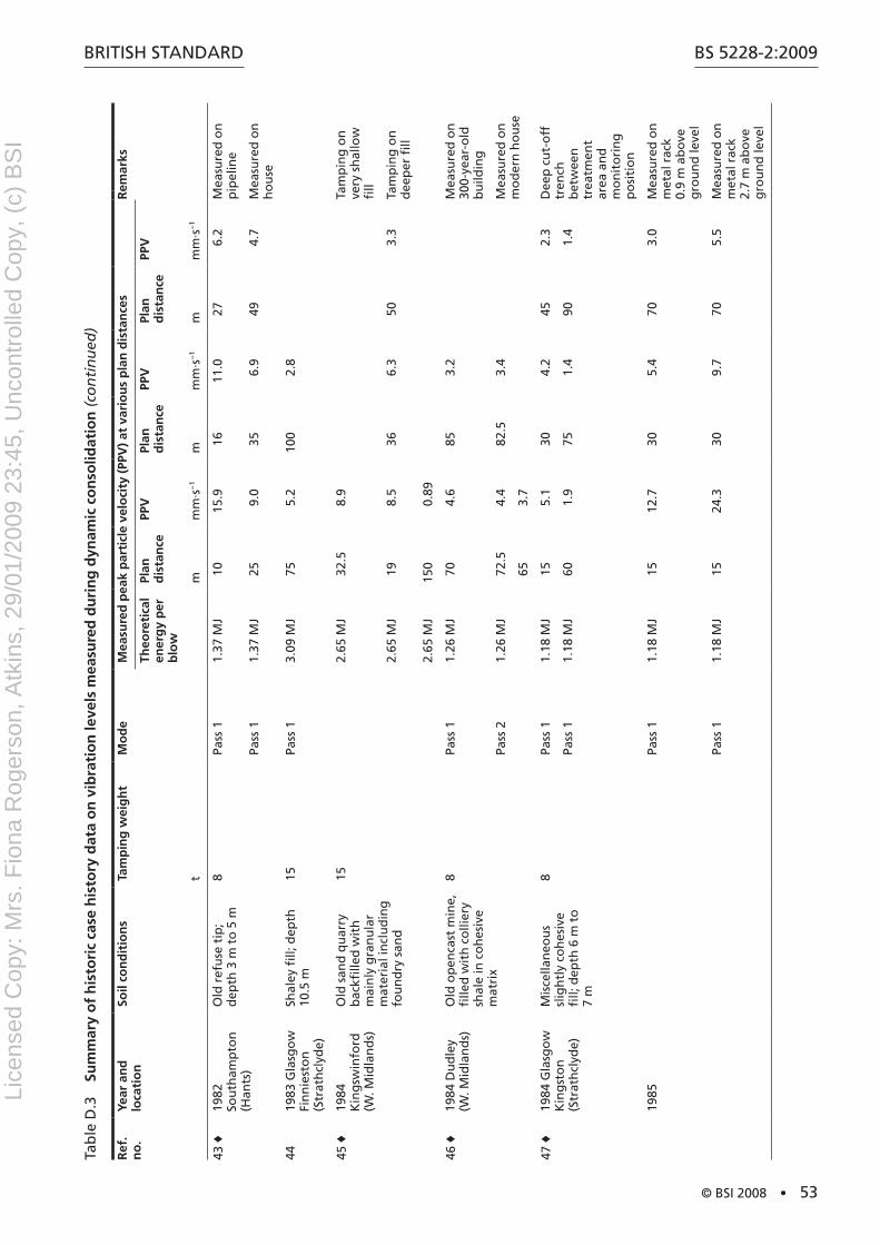
BritiSh Standard
© BSI 2008 • 53
BS 5228-2:2009
Ref
. n
o.
Year
an
d
loca
tio
nSo
il co
nd
itio
ns
Tam
pin
g w
eig
ht
Mo
de
Mea
sure
d p
eak
par
ticl
e ve
loci
ty (
PPV
) at
var
iou
s p
lan
dis
tan
ces
Rem
arks
Theo
reti
cal
ener
gy
per
b
low
Plan
d
ista
nce
PPV
Plan
d
ista
nce
PPV
Plan
d
ista
nce
PPV
tm
mm
·s−
1m
mm
·s−
1m
mm
·s−
1
43 ♦
1982
So
uth
amp
ton
(h
ants
)
Old
ref
use
tip
; d
epth
3 m
to
5 m
8Pa
ss 1
1.37
MJ
1015
.916
11.0
276.
2M
easu
red
on
p
ipel
ine
Pass
11.
37 M
J25
9.0
356.
949
4.7
Mea
sure
d o
n
ho
use
4419
83 G
lasg
ow
Fi
nn
iest
on
(S
trat
hcl
yde)
Shal
ey fi
ll; d
epth
10
.5 m
15Pa
ss 1
3.09
MJ
755.
210
02.
8
45 ♦
1984
K
ing
swin
ford
(W
. Mid
lan
ds)
Old
san
d q
uar
ry
bac
kfille
d w
ith
m
ain
ly g
ran
ula
r m
ater
ial i
ncl
ud
ing
fo
un
dry
san
d
152.
65 M
J32
.58.
9ta
mp
ing
on
ve
ry s
hal
low
fi
ll
2.65
MJ
198.
536
6.3
503.
3ta
mp
ing
on
d
eep
er fi
ll
2.65
MJ
150
0.89
46 ♦
1984
du
dle
y (W
. Mid
lan
ds)
Old
op
enca
st m
ine,
fi
lled
wit
h c
olli
ery
shal
e in
co
hes
ive
mat
rix
8Pa
ss 1
1.26
MJ
704.
685
3.2
Mea
sure
d o
n
300-
year
-old
b
uild
ing
Pass
21.
26 M
J72
.54.
482
.53.
4M
easu
red
on
m
od
ern
ho
use
653.
7
47 ♦
1984
Gla
sgo
w
Kin
gst
on
(S
trat
hcl
yde)
Mis
cella
neo
us
slig
htl
y co
hes
ive
fill;
dep
th 6
m t
o
7 m
8Pa
ss 1
1.18
MJ
155.
130
4.2
452.
3d
eep
cu
t-o
ff
tren
ch
bet
wee
n
trea
tmen
t ar
ea a
nd
m
on
ito
rin
g
po
siti
on
Pass
11.
18 M
J60
1.9
751.
490
1.4
1985
Pass
11.
18 M
J15
12.7
305.
470
3.0
Mea
sure
d o
n
met
al r
ack
0.9
m a
bo
ve
gro
un
d le
vel
Pass
11.
18 M
J15
24.3
309.
770
5.5
Mea
sure
d o
n
met
al r
ack
2.7
m a
bo
ve
gro
un
d le
vel
tab
le d
.3
Sum
mar
y o
f h
isto
ric
case
his
tory
dat
a o
n v
ibra
tio
n le
vels
mea
sure
d d
uri
ng
dyn
amic
co
nso
lidat
ion
(co
nti
nu
ed)
Lice
nsed
Cop
y: M
rs. F
iona
Rog
erso
n, A
tkin
s, 2
9/01
/200
9 23
:45,
Unc
ontr
olle
d C
opy,
(c)
BS
I
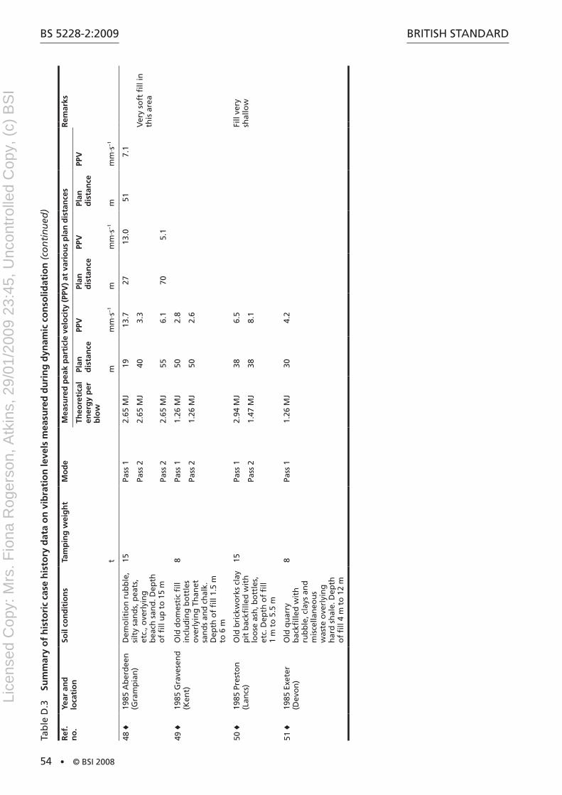
BS 5228-2:2009
54 • © BSI 2008
BritiSh Standard
Ref
. n
o.
Year
an
d
loca
tio
nSo
il co
nd
itio
ns
Tam
pin
g w
eig
ht
Mo
de
Mea
sure
d p
eak
par
ticl
e ve
loci
ty (
PPV
) at
var
iou
s p
lan
dis
tan
ces
Rem
arks
Theo
reti
cal
ener
gy
per
b
low
Plan
d
ista
nce
PPV
Plan
d
ista
nce
PPV
Plan
d
ista
nce
PPV
tm
mm
·s−
1m
mm
·s−
1m
mm
·s−
1
48 ♦
1985
ab
erd
een
(G
ram
pia
n)
dem
olit
ion
ru
bb
le,
silt
y sa
nd
s, p
eats
, et
c., o
verl
yin
g
bea
ch s
and
. dep
th
of
fill
up
to
15
m
15Pa
ss 1
2.65
MJ
1913
.727
13.0
517.
1
Pass
22.
65 M
J40
3.3
Ver
y so
ft fi
ll in
th
is a
rea
Pass
22.
65 M
J55
6.1
705.
1
49 ♦
1985
Gra
vese
nd
(K
ent)
Old
do
mes
tic
fill
incl
ud
ing
bo
ttle
s o
verl
yin
g t
han
et
san
ds
and
ch
alk.
d
epth
of
fill
1.5
m
to 6
m
8Pa
ss 1
1.26
MJ
502.
8
Pass
21.
26 M
J50
2.6
50 ♦
1985
Pre
sto
n
(Lan
cs)
Old
bri
ckw
ork
s cl
ay
pit
bac
kfille
d w
ith
lo
ose
ash
, bo
ttle
s,
etc.
dep
th o
f fi
ll 1
m t
o 5
.5 m
15Pa
ss 1
2.94
MJ
386.
5Fi
ll ve
ry
shal
low
Pass
21.
47 M
J38
8.1
51 ♦
1985
Exe
ter
(dev
on
)O
ld q
uar
ry
bac
kfille
d w
ith
ru
bb
le, c
lays
an
d
mis
cella
neo
us
was
te o
verl
yin
g
har
d s
hal
e. d
epth
o
f fi
ll 4
m t
o 1
2 m
8Pa
ss 1
1.26
MJ
304.
2
tab
le d
.3
Sum
mar
y o
f h
isto
ric
case
his
tory
dat
a o
n v
ibra
tio
n le
vels
mea
sure
d d
uri
ng
dyn
amic
co
nso
lidat
ion
(co
nti
nu
ed)
Lice
nsed
Cop
y: M
rs. F
iona
Rog
erso
n, A
tkin
s, 2
9/01
/200
9 23
:45,
Unc
ontr
olle
d C
opy,
(c)
BS
I
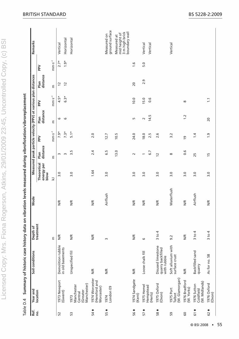
BritiSh Standard
© BSI 2008 • 55
BS 5228-2:2009
tab
le d
.4
Sum
mar
y o
f h
isto
ric
case
his
tory
dat
a o
n v
ibra
tio
n le
vels
mea
sure
d d
uri
ng
vib
rofl
ota
tio
n/v
ibro
rep
lace
men
t
Ref
. n
o.
Year
an
d
loca
tio
nSo
il co
nd
itio
ns
Dep
th o
f tr
eatm
ent
Mo
de
Mea
sure
d p
eak
par
ticl
e ve
loci
ty (
PPV
) at
var
iou
s p
lan
dis
tan
ces
Rem
arks
Theo
reti
cal
ener
gy
per
b
low
Plan
d
ista
nce
PPV
Plan
d
ista
nce
PPV
Plan
d
ista
nce
PPV
mkJ
mm
m·s
−1
mm
m·s
−1
mm
m·s
−1
5219
73 n
ewp
ort
(G
wen
t)d
emo
litio
n r
ub
ble
in
old
bas
emen
tsn
/rn
/r3.
03
7.9*
64.
5*12
2.7*
Ver
tica
l
37.
3*6
6.3*
121.
9*h
ori
zon
tal
5319
73
Man
ches
ter
Cen
tral
(G
reat
er
Man
ches
ter)
Un
spec
ified
fill
n/r
n/r
3.0
3.5
5.1*
ho
rizo
nta
l
54 ♦
1974
Wo
rces
ter
(her
efo
rd a
nd
W
orc
este
r)
n/r
n/r
n/r
1.64
2.4
2.0
55 ♦
1974
Lo
nd
on
E9
n/r
3a
irfl
ush
3.0
6.5
12.7
Mea
sure
d o
n
gro
un
d s
urf
ace
13.0
10.5
Mea
sure
d a
t m
id h
eig
ht
of
3 m
hig
h b
rick
b
ou
nd
ary
wal
l
56 ♦
1974
San
dg
ate
(Ken
t)n
/rn
/rn
/r3.
02
24.0
510
.020
1.6
57 ♦
1975
hem
el
hem
pst
ead
(h
erts
)
Loo
se c
hal
k fi
ll6
n/r
3.0
118
.02
15.0
2.9
5.0
Ver
tica
l
6.7
2.5
14.5
0.6
Ver
tica
l
58 ♦
1975
Oxf
ord
(O
xon
)d
isu
sed
lim
esto
ne
qu
arry
bac
kfille
d
wit
h r
ub
ble
3 to
4n
/r3.
012
2.6
5919
75 P
ort
ta
lbo
t (W
. Gla
mo
rgan
)
Soft
allu
viu
m w
ith
su
rfac
e cr
ust
9.2
Wat
erfl
ush
3.0
83.
2V
erti
cal
6019
76 B
rad
ford
(W
. Yo
rks)
n/r
n/r
n/r
3.0
0.6
191.
28
61 ♦
1976
Su
tto
n
Co
ldfi
eld
(W
. Mid
lan
ds)
Bac
kfille
d s
and
q
uar
ry3
to 4
air
flu
sh3.
025
1.4
62 ♦
1976
Oxf
ord
(O
xon
)a
s fo
r n
o. 5
83
to 4
n/r
3.0
151.
920
1.1
Lice
nsed
Cop
y: M
rs. F
iona
Rog
erso
n, A
tkin
s, 2
9/01
/200
9 23
:45,
Unc
ontr
olle
d C
opy,
(c)
BS
I
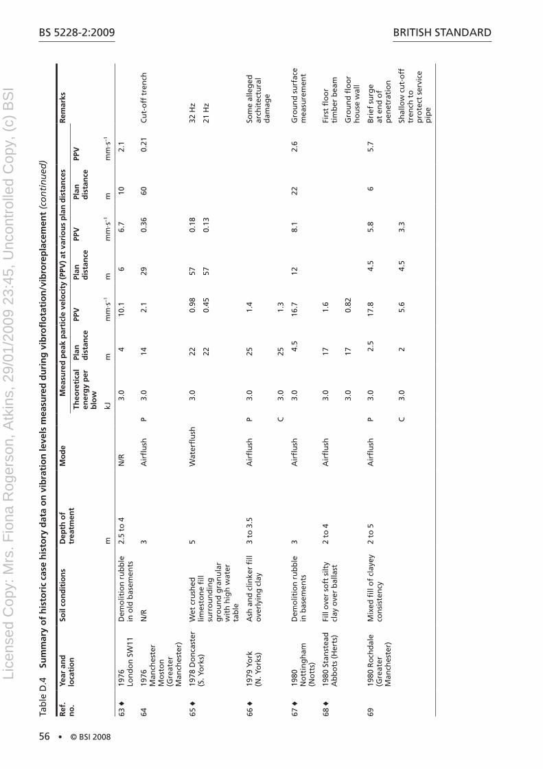
BS 5228-2:2009
56 • © BSI 2008
BritiSh Standard
Ref
. n
o.
Year
an
d
loca
tio
nSo
il co
nd
itio
ns
Dep
th o
f tr
eatm
ent
Mo
de
Mea
sure
d p
eak
par
ticl
e ve
loci
ty (
PPV
) at
var
iou
s p
lan
dis
tan
ces
Rem
arks
Theo
reti
cal
ener
gy
per
b
low
Plan
d
ista
nce
PPV
Plan
d
ista
nce
PPV
Plan
d
ista
nce
PPV
mkJ
mm
m·s
−1
mm
m·s
−1
mm
m·s
−1
63 ♦
1976
Lo
nd
on
SW
11d
emo
litio
n r
ub
ble
in
old
bas
emen
ts2.
5 to
4n
/r3.
04
10.1
66.
710
2.1
6419
76
Man
ches
ter
Mo
sto
n
(Gre
ater
M
anch
este
r)
n/r
3a
irfl
ush
P3.
014
2.1
290.
3660
0.21
Cu
t-o
ff t
ren
ch
65 ♦
1978
do
nca
ster
(S
. Yo
rks)
Wet
cru
shed
lim
esto
ne
fill
surr
ou
nd
ing
g
rou
nd
gra
nu
lar
wit
h h
igh
wat
er
tab
le
5W
ater
flu
sh3.
022
0.98
570.
1832
hz
220.
4557
0.13
21 h
z
66 ♦
1979
Yo
rk
(n. Y
ork
s)a
sh a
nd
clin
ker
fill
ove
rlyi
ng
cla
y3
to 3
.5a
irfl
ush
P3.
025
1.4
Som
e al
leg
ed
arch
itec
tura
l d
amag
e
C3.
025
1.3
67 ♦
1980
n
ott
ing
ham
(n
ott
s)
dem
olit
ion
ru
bb
le
in b
asem
ents
3a
irfl
ush
3.0
4.5
16.7
128.
122
2.6
Gro
un
d s
urf
ace
mea
sure
men
t
68 ♦
1980
Sta
nst
ead
a
bb
ots
(h
erts
)Fi
ll o
ver
soft
silt
y cl
ay o
ver
bal
last
2 to
4a
irfl
ush
3.0
171.
6Fi
rst
flo
or
tim
ber
bea
m
3.0
170.
82G
rou
nd
flo
or
ho
use
wal
l
6919
80 r
och
dal
e (G
reat
er
Man
ches
ter)
Mix
ed fi
ll o
f cl
ayey
co
nsi
sten
cy2
to 5
air
flu
shP
3.0
2.5
17.8
4.5
5.8
65.
7B
rief
su
rge
at e
nd
of
pen
etra
tio
n
C3.
02
5.6
4.5
3.3
Shal
low
cu
t-o
ff
tren
ch t
o
pro
tect
ser
vice
p
ipe
tab
le d
.4
Sum
mar
y o
f h
isto
ric
case
his
tory
dat
a o
n v
ibra
tio
n le
vels
mea
sure
d d
uri
ng
vib
rofl
ota
tio
n/v
ibro
rep
lace
men
t (c
on
tin
ued
)
Lice
nsed
Cop
y: M
rs. F
iona
Rog
erso
n, A
tkin
s, 2
9/01
/200
9 23
:45,
Unc
ontr
olle
d C
opy,
(c)
BS
I
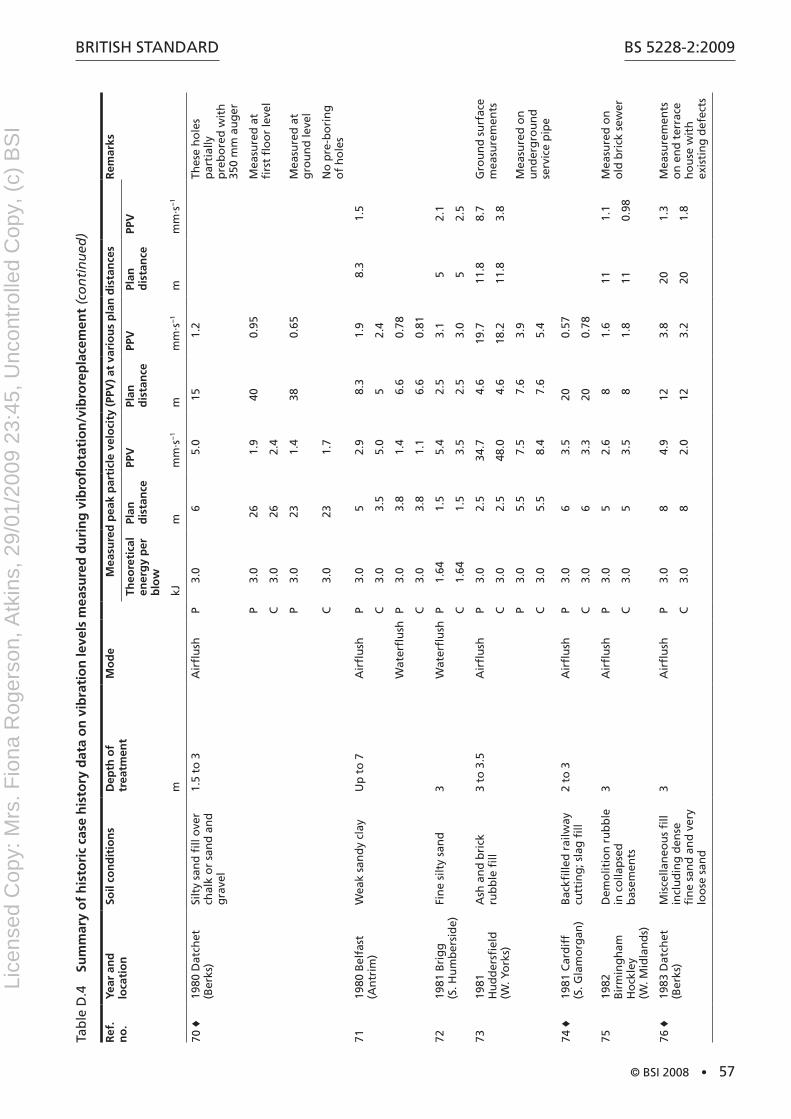
BritiSh Standard
© BSI 2008 • 57
BS 5228-2:2009
Ref
. n
o.
Year
an
d
loca
tio
nSo
il co
nd
itio
ns
Dep
th o
f tr
eatm
ent
Mo
de
Mea
sure
d p
eak
par
ticl
e ve
loci
ty (
PPV
) at
var
iou
s p
lan
dis
tan
ces
Rem
arks
Theo
reti
cal
ener
gy
per
b
low
Plan
d
ista
nce
PPV
Plan
d
ista
nce
PPV
Plan
d
ista
nce
PPV
mkJ
mm
m·s
−1
mm
m·s
−1
mm
m·s
−1
70 ♦
1980
dat
chet
(B
erks
)Si
lty
san
d fi
ll o
ver
chal
k o
r sa
nd
an
d
gra
vel
1.5
to 3
air
flu
shP
3.0
65.
015
1.2
thes
e h
ole
s p
arti
ally
p
reb
ore
d w
ith
35
0 m
m a
ug
er
P3.
026
1.9
400.
95M
easu
red
at
firs
t fl
oo
r le
vel
C3.
026
2.4
P3.
023
1.4
380.
65M
easu
red
at
gro
un
d le
vel
C3.
023
1.7
no
pre
-bo
rin
g
of
ho
les
7119
80 B
elfa
st
(an
trim
)W
eak
san
dy
clay
Up
to
7a
irfl
ush
P3.
05
2.9
8.3
1.9
8.3
1.5
C3.
03.
55.
05
2.4
Wat
erfl
ush
P3.
03.
81.
46.
60.
78
C3.
03.
81.
16.
60.
81
7219
81 B
rig
g
(S. h
um
ber
sid
e)Fi
ne
silt
y sa
nd
3W
ater
flu
shP
1.64
1.5
5.4
2.5
3.1
52.
1
C1.
641.
53.
52.
53.
05
2.5
7319
81
hu
dd
ersfi
eld
(W
. Yo
rks)
ash
an
d b
rick
ru
bb
le fi
ll3
to 3
.5a
irfl
ush
P3.
02.
534
.74.
619
.711
.88.
7G
rou
nd
su
rfac
e m
easu
rem
ents
C3.
02.
548
.04.
618
.211
.83.
8
P3.
05.
57.
57.
63.
9M
easu
red
on
u
nd
erg
rou
nd
se
rvic
e p
ipe
C3.
05.
58.
47.
65.
4
74 ♦
1981
Car
dif
f (S
. Gla
mo
rgan
)B
ackfi
lled
rai
lway
cu
ttin
g; s
lag
fill
2 to
3a
irfl
ush
P3.
06
3.5
200.
57
C3.
06
3.3
200.
78
7519
82
Bir
min
gh
am
ho
ckle
y (W
. Mid
lan
ds)
dem
olit
ion
ru
bb
le
in c
olla
pse
d
bas
emen
ts
3a
irfl
ush
P3.
05
2.6
81.
611
1.1
Mea
sure
d o
n
old
bri
ck s
ewer
C3.
05
3.5
81.
811
0.98
76 ♦
1983
dat
chet
(B
erks
)M
isce
llan
eou
s fi
ll in
clu
din
g d
ense
fi
ne
san
d a
nd
ver
y lo
ose
san
d
3a
irfl
ush
P3.
08
4.9
123.
820
1.3
Mea
sure
men
ts
on
en
d t
erra
ce
ho
use
wit
h
exis
tin
g d
efec
ts
C3.
08
2.0
123.
220
1.8
tab
le d
.4
Sum
mar
y o
f h
isto
ric
case
his
tory
dat
a o
n v
ibra
tio
n le
vels
mea
sure
d d
uri
ng
vib
rofl
ota
tio
n/v
ibro
rep
lace
men
t (c
on
tin
ued
)
Lice
nsed
Cop
y: M
rs. F
iona
Rog
erso
n, A
tkin
s, 2
9/01
/200
9 23
:45,
Unc
ontr
olle
d C
opy,
(c)
BS
I
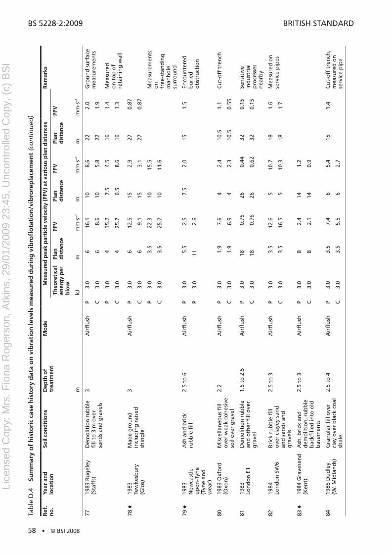
BS 5228-2:2009
58 • © BSI 2008
BritiSh Standard
Ref
. n
o.
Year
an
d
loca
tio
nSo
il co
nd
itio
ns
Dep
th o
f tr
eatm
ent
Mo
de
Mea
sure
d p
eak
par
ticl
e ve
loci
ty (
PPV
) at
var
iou
s p
lan
dis
tan
ces
Rem
arks
Theo
reti
cal
ener
gy
per
b
low
Plan
d
ista
nce
PPV
Plan
d
ista
nce
PPV
Plan
d
ista
nce
PPV
mkJ
mm
m·s
−1
mm
m·s
−1
mm
m·s
−1
7719
83 r
ug
eley
(S
taff
s)d
emo
litio
n r
ub
ble
fi
ll to
3 m
ove
r sa
nd
s an
d g
rave
ls
3a
irfl
ush
P3.
06
16.1
108.
622
2.0
Gro
un
d s
urf
ace
mea
sure
men
tsC
3.0
68.
610
5.8
221.
9
P3.
04
35.2
7.5
4.5
161.
4M
easu
red
o
n t
op
of
reta
inin
g w
all
C3.
04
25.7
6.5
8.6
161.
3
78 ♦
1983
te
wke
sbu
ry
(Glo
s)
Mad
e g
rou
nd
in
clu
din
g r
aise
d
shin
gle
3a
irfl
ush
P3.
06
12.5
152.
927
0.87
C3.
06
9.1
153.
127
0.87
P3.
03.
522
.310
15.5
Mea
sure
men
ts
on
fr
ee-s
tan
din
g
man
ho
le
surr
ou
nd
C3.
03.
525
.710
11.6
79 ♦
1983
n
ewca
stle
- u
po
n-t
yne
(tyn
e an
d
wea
r)
ash
an
d b
rick
ru
bb
le fi
ll2.
5 to
6a
irfl
ush
P3.
05.
52.
57.
52.
015
1.5
Enco
un
tere
d
bu
ried
o
bst
ruct
ion
P3.
011
2.6
8019
83 O
xfo
rd
(Oxo
n)
Mis
cella
neo
us
fill
ove
r w
eak
coh
esiv
e so
il o
ver
gra
vel
2.2
air
flu
shP
3.0
1.9
7.6
42.
410
.51.
1C
ut-
off
tre
nch
C3.
01.
96.
94
2.3
10.5
0.55
8119
83
Lon
do
n E
1d
emo
litio
n r
ub
ble
an
d o
ther
fill
ove
r g
rave
l
1.5
to 2
.5a
irfl
ush
P3.
018
0.75
260.
4432
0.15
Sen
siti
ve
ind
ust
rial
p
roce
sses
n
earb
y
C3.
018
0.76
260.
6232
0.15
8219
84
Lon
do
n S
W6
Bri
ck r
ub
ble
fill
ove
r cl
ayey
san
d
and
san
ds
and
g
rave
ls
2.5
to 3
air
flu
shP
3.0
3.5
12.6
510
.718
1.6
Mea
sure
d o
n
serv
ice
pip
esC
3.0
3.5
16.5
510
.318
1.7
83 ♦
1984
Gra
vese
nd
(K
ent)
ash
, bri
ck a
nd
d
emo
litio
n, r
ub
ble
b
ackfi
lled
into
old
b
asem
ents
2.5
to 3
air
flu
shP
3.0
82.
414
1.2
C3.
08
2.1
140.
9
8419
85 d
ud
ley
(W. M
idla
nd
s)G
ran
ula
r fi
ll o
ver
clay
ove
r b
lack
co
al
shal
e
2.5
to 4
air
flu
shP
3.0
3.5
7.4
65.
415
1.4
Cu
t-o
ff t
ren
ch,
mea
sure
d o
n
serv
ice
pip
eC
3.0
3.5
5.5
62.
7
tab
le d
.4
Sum
mar
y o
f h
isto
ric
case
his
tory
dat
a o
n v
ibra
tio
n le
vels
mea
sure
d d
uri
ng
vib
rofl
ota
tio
n/v
ibro
rep
lace
men
t (c
on
tin
ued
)
Lice
nsed
Cop
y: M
rs. F
iona
Rog
erso
n, A
tkin
s, 2
9/01
/200
9 23
:45,
Unc
ontr
olle
d C
opy,
(c)
BS
I

BritiSh Standard
© BSI 2008 • 59
BS 5228-2:2009
Ref
. n
o.
Year
an
d
loca
tio
nSo
il co
nd
itio
ns
Dep
th o
f tr
eatm
ent
Mo
de
Mea
sure
d p
eak
par
ticl
e ve
loci
ty (
PPV
) at
var
iou
s p
lan
dis
tan
ces
Rem
arks
Theo
reti
cal
ener
gy
per
b
low
Plan
d
ista
nce
PPV
Plan
d
ista
nce
PPV
Plan
d
ista
nce
PPV
mkJ
mm
m·s
−1
mm
m·s
−1
mm
m·s
−1
85 ♦
1985
B
irm
ing
ham
B
ord
esle
y
(W. M
idla
nd
s)
Mis
cella
neo
us
fill
ove
r st
iff
clay
2 to
2.5
air
flu
shP
3.0
3.5
7.7
Cu
t-o
ff t
ren
ch
C3.
03.
54.
2
86 ♦
1985
hu
ll (n
. hu
mb
ersi
de)
Mis
cella
neo
us
fill
ove
r d
ense
loam
y sa
nd
4a
irfl
ush
3.0
128.
1
87 ♦
1985
Wo
rces
ter
(her
efo
rd a
nd
W
orc
este
r)
Fill
incl
ud
ing
sa
nd
s, r
ub
ble
an
d
po
rcel
ain
was
te
ove
r d
ense
gra
vel
3a
irfl
ush
P3.
09
5.5
133.
326
1.2
Cu
t-o
ff t
ren
ch
tab
le d
.5
Sum
mar
y o
f h
isto
ric
case
his
tory
dat
a o
n v
ibra
tio
n le
vels
mea
sure
d d
uri
ng
th
e u
se o
f ca
sin
g v
ibra
tors
Ref
. n
o.
Year
an
d
loca
tio
nSo
il co
nd
itio
ns
Pile
dim
ensi
on
sM
od
eM
easu
red
pea
k p
arti
cle
velo
city
(PP
V)
at v
ario
us
pla
n d
ista
nce
sR
emar
ks
Theo
reti
cal
ener
gy
per
b
low
Plan
d
ista
nce
PPV
Plan
d
ista
nce
PPV
Plan
d
ista
nce
PPV
kJm
mm
·s−
1m
mm
·s−
1m
mm
·s−
1
8819
73 is
le o
f G
rain
(K
ent)
hyd
rau
lical
ly
pla
ced
san
dfi
ll o
ver
estu
aria
l silt
s o
ver
bal
last
ove
r Lo
nd
on
cla
y
815
mm
z 2
4.4
m
dep
th p
erm
anen
t lin
er
dri
vin
g li
ner
4.35
to
6.3
110
23.
23
0.8
25 h
z
dri
vin
g li
ner
6.9
to 8
.58
4.1
112.
216
1.5
12 h
z to
15
hz
89 ♦
1974
Lo
nd
on
W6
Fill
ove
r b
alla
st
ove
r Lo
nd
on
cla
y75
0 m
m t
o
1 05
0 m
m z
2.5
m
to 9
m d
epth
dri
vin
g
casi
ng
2.18
to
3.
151.
38.
02
6.4
6.6
1.5
Ver
tica
l 25
hz
Extr
acti
ng
ca
sin
g2.
18 t
o
3.15
25.
06.
63.
2V
erti
cal 2
5 h
z Se
nsi
tive
eq
uip
men
t in
ad
jace
nt
bu
ildin
g
90 ♦
1976
Lo
nd
on
EC
4Fi
ll o
ver
bal
last
o
ver
Lon
do
n c
lay
750
mm
to
1
050
mm
zd
rivi
ng
ca
sin
g2.
18 t
o
3.15
35.
825
hz
91 ♦
1976
Lo
nd
on
E1
Fill
ove
r b
alla
st
ove
r Lo
nd
on
cla
yn
/rd
rivi
ng
ca
sin
g2.
18 t
o
3.15
104
251.
525
hz
tab
le d
.4
Sum
mar
y o
f h
isto
ric
case
his
tory
dat
a o
n v
ibra
tio
n le
vels
mea
sure
d d
uri
ng
vib
rofl
ota
tio
n/v
ibro
rep
lace
men
t (c
on
tin
ued
)
Lice
nsed
Cop
y: M
rs. F
iona
Rog
erso
n, A
tkin
s, 2
9/01
/200
9 23
:45,
Unc
ontr
olle
d C
opy,
(c)
BS
I
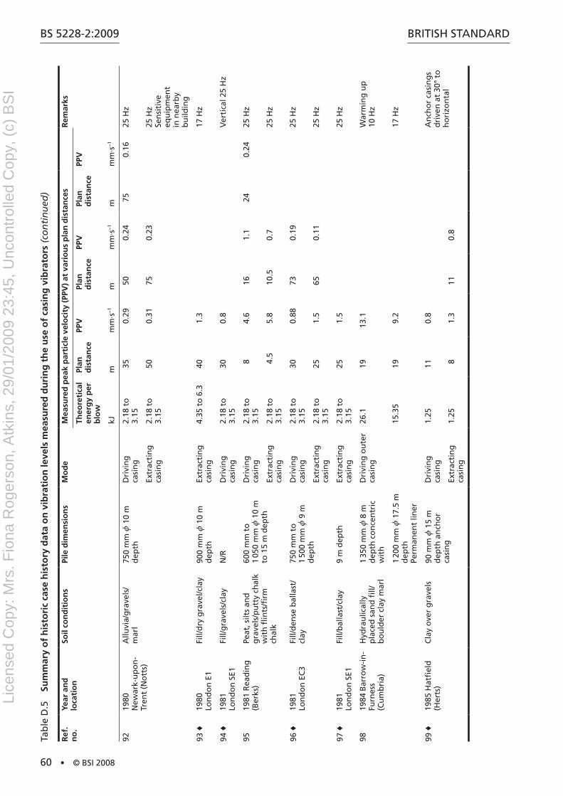
BS 5228-2:2009
60 • © BSI 2008
BritiSh Standard
Ref
. n
o.
Year
an
d
loca
tio
nSo
il co
nd
itio
ns
Pile
dim
ensi
on
sM
od
eM
easu
red
pea
k p
arti
cle
velo
city
(PP
V)
at v
ario
us
pla
n d
ista
nce
sR
emar
ks
Theo
reti
cal
ener
gy
per
b
low
Plan
d
ista
nce
PPV
Plan
d
ista
nce
PPV
Plan
d
ista
nce
PPV
kJm
mm
·s−
1m
mm
·s−
1m
mm
·s−
1
9219
80
new
ark-
up
on
- tr
ent
(no
tts)
allu
via/
gra
vels
/ m
arl
750
mm
z 1
0 m
d
epth
dri
vin
g
casi
ng
2.18
to
3.
1535
0.29
500.
2475
0.16
25 h
z
Extr
acti
ng
ca
sin
g2.
18 t
o
3.15
500.
3175
0.23
25 h
z
Sen
siti
ve
equ
ipm
ent
in n
earb
y b
uild
ing
93 ♦
1980
Lo
nd
on
E1
Fill/
dry
gra
vel/c
lay
900
mm
z 1
0 m
d
epth
Extr
acti
ng
ca
sin
g4.
35 t
o 6
.340
1.3
17 h
z
94 ♦
1981
Lo
nd
on
SE1
Fill/
gra
vels
/cla
yn
/rd
rivi
ng
ca
sin
g2.
18 t
o
3.15
300.
8V
erti
cal 2
5 h
z
9519
81 r
ead
ing
(B
erks
)Pe
at, s
ilts
and
g
rave
ls/p
utt
y ch
alk
wit
h fl
ints
/firm
ch
alk
600
mm
to
1
050
mm
z 1
0 m
to
15
m d
epth
dri
vin
g
casi
ng
2.18
to
3.
158
4.6
161.
124
0.24
25 h
z
Extr
acti
ng
ca
sin
g2.
18 t
o
3.15
4.5
5.8
10.5
0.7
25 h
z
96 ♦
1981
Lo
nd
on
EC
3Fi
ll/d
ense
bal
last
/cl
ay75
0 m
m t
o
1 50
0 m
m z
9 m
d
epth
dri
vin
g
casi
ng
2.18
to
3.
1530
0.88
730.
1925
hz
Extr
acti
ng
ca
sin
g2.
18 t
o
3.15
251.
565
0.11
25 h
z
97 ♦
1981
Lo
nd
on
SE1
Fill/
bal
last
/cla
y9
m d
epth
Extr
acti
ng
ca
sin
g2.
18 t
o
3.15
251.
525
hz
9819
84 B
arro
w-i
n-
Furn
ess
(Cu
mb
ria)
hyd
rau
lical
ly
pla
ced
san
d fi
ll/b
ou
lder
cla
y m
arl
1 35
0 m
m z
8 m
d
epth
co
nce
ntr
ic
wit
h
dri
vin
g o
ute
r ca
sin
g26
.119
13.1
War
min
g u
p
10 h
z
1 20
0 m
m z
17.
5 m
d
epth
Pe
rman
ent
liner
15.3
519
9.2
17 h
z
99 ♦
1985
hat
fiel
d
(her
ts)
Cla
y o
ver
gra
vels
90 m
m z
15
m
dep
th a
nch
or
casi
ng
dri
vin
g
casi
ng
1.25
110.
8a
nch
or
casi
ng
s d
rive
n a
t 30
° to
h
ori
zon
tal
Extr
acti
ng
ca
sin
g1.
258
1.3
110.
8
tab
le d
.5
Sum
mar
y o
f h
isto
ric
case
his
tory
dat
a o
n v
ibra
tio
n le
vels
mea
sure
d d
uri
ng
th
e u
se o
f ca
sin
g v
ibra
tors
(co
nti
nu
ed)
Lice
nsed
Cop
y: M
rs. F
iona
Rog
erso
n, A
tkin
s, 2
9/01
/200
9 23
:45,
Unc
ontr
olle
d C
opy,
(c)
BS
I

BritiSh Standard
© BSI 2008 • 61
BS 5228-2:2009
tab
le d
.6
Sum
mar
y o
f h
isto
ric
case
his
tory
dat
a o
n v
ibra
tio
n le
vels
mea
sure
d d
uri
ng
ro
tary
bo
red
pili
ng
(in
clu
din
g c
asin
g d
olli
es)
Ref
. n
o.
Year
an
d
loca
tio
nSo
il co
nd
itio
ns
Pile
dim
ensi
on
sM
od
eM
easu
red
pea
k p
arti
cle
velo
city
(PP
V)
at v
ario
us
pla
n d
ista
nce
sR
emar
ks
Theo
reti
cal
ener
gy
per
b
low
Plan
d
ista
nce
PPV
Plan
d
ista
nce
PPV
Plan
d
ista
nce
PPV
kJm
mm
·s−
1m
mm
·s−
1m
mm
·s−
1
100
♦19
74
Lon
do
n W
6Fi
ll/g
rave
l/Lo
nd
on
cl
ayn
/rd
rivi
ng
ca
sin
g7
3.2
ho
rizo
nta
l
Wit
h 3
t d
olly
71.
0V
erti
cal
101
1981
Lo
nd
on
EC
3Fi
ll/d
ense
bal
last
/Lo
nd
on
cla
y1
050
mm
za
ug
erin
g20
0.05
List
ed b
uild
ing
n
earb
y
au
ger
hit
tin
g
bas
e o
f h
ole
200.
23
102
1982
C
hel
ten
ham
(G
los.
)
Fill/
wet
san
d/li
as
clay
900
mm
za
ug
erin
g9
0.2
List
ed b
uild
ing
ad
jace
nt
to s
ite
ham
mer
ing
ca
sin
g w
ith
K
elly
bar
90.
8
103
1983
ro
mfo
rd
(Gre
ater
Lo
nd
on
)
Fill
clay
350
mm
z 1
4.5
m
dep
tha
ug
erin
g10
0.38
200.
330
0.03
do
llyin
g
casi
ng
11.8
101.
120
0.55
2 t
do
lly
au
ger
hit
tin
g
bas
e o
f h
ole
100.
96
Spin
nin
g o
ff10
0.57
200.
44
104
1985
Lo
nd
on
W1
Fill/
san
d/c
lay
500
mm
za
ug
erin
g10
0.4
150.
126
0.02
au
ger
hit
tin
g
bas
e o
f h
ole
140.
326
0.1
Mu
dd
ing
in10
0.3
140.
2
Spin
nin
g o
ff10
0.3
do
llyin
g
casi
ng
11.8
101.
014
0.8
2 t
do
lly
105
1985
St.
alb
ans
(her
ts)
San
ds
and
gra
vels
o
ver
chal
k60
0 m
m z
12
m
dep
tha
ug
erin
g3.
50.
238
0.04
au
ger
hit
tin
g
bas
e o
f h
ole
3.5
2.4
81.
7
Spin
nin
g o
ff6
0.08
80.
06
Lice
nsed
Cop
y: M
rs. F
iona
Rog
erso
n, A
tkin
s, 2
9/01
/200
9 23
:45,
Unc
ontr
olle
d C
opy,
(c)
BS
I

BS 5228-2:2009
62 • © BSI 2008
BritiSh Standard
Ref
. n
o.
Year
an
d
loca
tio
nSo
il co
nd
itio
ns
Pile
dim
ensi
on
sM
od
eM
easu
red
pea
k p
arti
cle
velo
city
(PP
V)
at v
ario
us
pla
n d
ista
nce
sR
emar
ks
Theo
reti
cal
ener
gy
per
b
low
Plan
d
ista
nce
PPV
Plan
d
ista
nce
PPV
Plan
d
ista
nce
PPV
kJm
mm
·s−
1m
mm
·s−
1m
mm
·s−
1
106
1985
Po
rtla
nd
(d
ors
et)
6 m
of
soft
gro
un
d
ove
r ro
ck60
0 m
m z
7 m
d
epth
au
ger
ing
50.
54Se
nsi
tive
eq
uip
men
t in
ad
jace
nt
bu
ildin
g
Surg
ing
ca
sin
g5
0.36
twis
tin
g in
ca
sin
g5
0.22
Spin
nin
g o
ff5
0.42
Bo
rin
g w
ith
ro
ck a
ug
er5
0.43
107
1985
Uxb
rid
ge
(Gre
ater
Lo
nd
on
)
Fill
incl
ud
ing
p
ock
ets
of
gra
vel
ove
r Lo
nd
on
cla
y
350
mm
z 7
m
dep
tha
ug
erin
g5.
50.
13Pr
ebo
rin
g f
or
a d
rive
n p
ile
tab
le d
.7
Sum
mar
y o
f h
isto
ric
case
his
tory
dat
a o
n v
ibra
tio
n le
vels
mea
sure
d d
uri
ng
tri
po
d b
ore
d p
ilin
g
Ref
. n
o.
Year
an
d
loca
tio
nSo
il co
nd
itio
ns
Pile
dim
ensi
on
sM
od
eM
easu
red
pea
k p
arti
cle
velo
city
(PP
V)
at v
ario
us
pla
n d
ista
nce
sR
emar
ks
Theo
reti
cal
ener
gy
per
b
low
Plan
d
ista
nce
PPV
Plan
d
ista
nce
PPV
Plan
d
ista
nce
PPV
kJm
mm
·s−
1m
mm
·s−
1m
mm
·s−
1
C1
♦19
71
Lon
do
n W
C2
Ove
rbu
rden
ove
r Lo
nd
on
cla
yn
/rd
rivi
ng
ca
sin
gn
/r1
12.5
C2
♦19
71
Lon
do
n S
W1
San
d a
nd
gra
vel
ove
r Lo
nd
on
cla
y50
0 m
m z
17
m
dep
thn
/rn
/r11
2.6
420.
31
C3
♦B
ury
(G
reat
er
Man
ches
ter)
San
d a
nd
gra
vel/
soft
silt
y cl
ay/h
ard
g
laci
al t
ill
300
mm
zn
/rn
/r15
4.0
tab
le d
.6
Sum
mar
y o
f h
isto
ric
case
his
tory
dat
a o
n v
ibra
tio
n le
vels
mea
sure
d d
uri
ng
ro
tary
bo
red
pili
ng
(in
clu
din
g c
asin
g d
olli
es)
(co
nti
nu
ed)
Lice
nsed
Cop
y: M
rs. F
iona
Rog
erso
n, A
tkin
s, 2
9/01
/200
9 23
:45,
Unc
ontr
olle
d C
opy,
(c)
BS
I
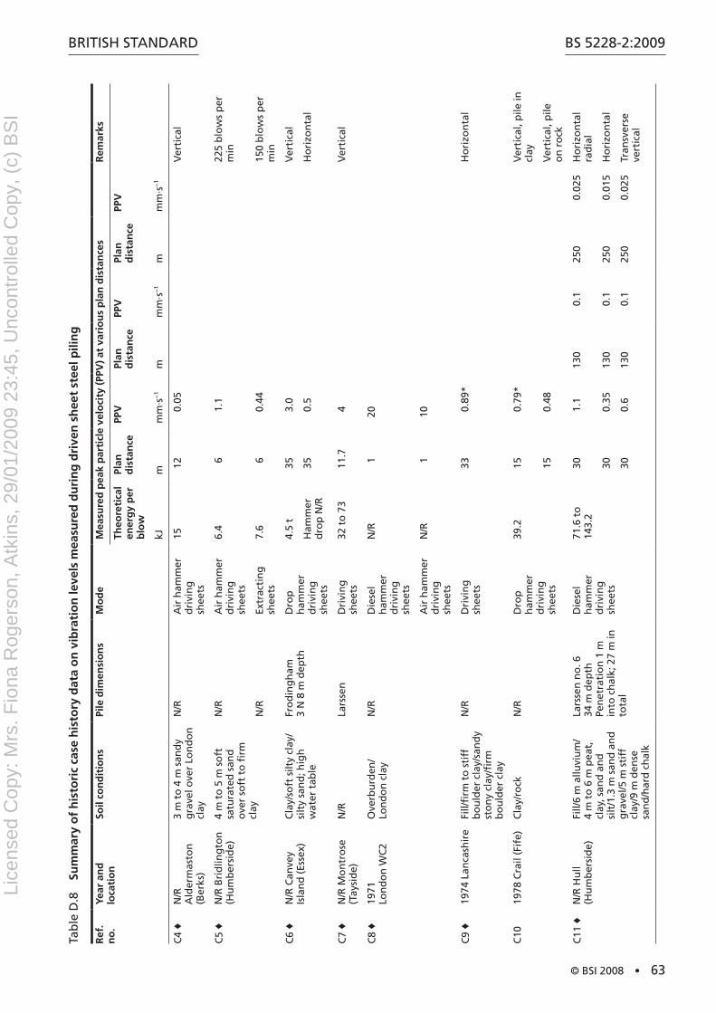
BritiSh Standard
© BSI 2008 • 63
BS 5228-2:2009
tab
le d
.8
Sum
mar
y o
f h
isto
ric
case
his
tory
dat
a o
n v
ibra
tio
n le
vels
mea
sure
d d
uri
ng
dri
ven
sh
eet
stee
l pili
ng
Ref
. n
o.
Year
an
d
loca
tio
nSo
il co
nd
itio
ns
Pile
dim
ensi
on
sM
od
eM
easu
red
pea
k p
arti
cle
velo
city
(PP
V)
at v
ario
us
pla
n d
ista
nce
sR
emar
ks
Theo
reti
cal
ener
gy
per
b
low
Plan
d
ista
nce
PPV
Plan
d
ista
nce
PPV
Plan
d
ista
nce
PPV
kJm
mm
·s−
1m
mm
·s−
1m
mm
·s−
1
C4
♦n
/r
ald
erm
asto
n
(Ber
ks)
3 m
to
4 m
san
dy
gra
vel o
ver
Lon
do
n
clay
n/r
air
ham
mer
d
rivi
ng
sh
eets
1512
0.05
Ver
tica
l
C5
♦n
/r B
rid
ling
ton
(h
um
ber
sid
e)4
m t
o 5
m s
oft
sa
tura
ted
san
d
ove
r so
ft t
o fi
rm
clay
n/r
air
ham
mer
d
rivi
ng
sh
eets
6.4
61.
122
5 b
low
s p
er
min
n/r
Extr
acti
ng
sh
eets
7.6
60.
4415
0 b
low
s p
er
min
C6
♦n
/r C
anve
y is
lan
d (
Esse
x)C
lay/
soft
silt
y cl
ay/
silt
y sa
nd
; hig
h
wat
er t
able
Fro
din
gh
am
3 n
8 m
dep
thd
rop
h
amm
er
dri
vin
g
shee
ts
4.5
t35
3.0
Ver
tica
l
ham
mer
d
rop
n/r
350.
5h
ori
zon
tal
C7
♦n
/r M
on
tro
se
(tay
sid
e)n
/rLa
rsse
nd
rivi
ng
sh
eets
32 t
o 7
311
.74
Ver
tica
l
C8
♦19
71
Lon
do
n W
C2
Ove
rbu
rden
/Lo
nd
on
cla
yn
/rd
iese
l h
amm
er
dri
vin
g
shee
ts
n/r
120
air
ham
mer
d
rivi
ng
sh
eets
n/r
110
C9
♦19
74 L
anca
shir
eFi
ll/fi
rm t
o s
tiff
b
ou
lder
cla
y/sa
nd
y st
on
y cl
ay/fi
rm
bo
uld
er c
lay
n/r
dri
vin
g
shee
ts33
0.89
*h
ori
zon
tal
C10
1978
Cra
il (F
ife)
Cla
y/ro
ckn
/rd
rop
h
amm
er
dri
vin
g
shee
ts
39.2
150.
79*
Ver
tica
l, p
ile in
cl
ay
150.
48V
erti
cal,
pile
o
n r
ock
C11
♦n
/r h
ull
(hu
mb
ersi
de)
Fill/
6 m
allu
viu
m/
4 m
to
6 m
pea
t,
clay
, san
d a
nd
si
lt/1
.3 m
san
d a
nd
g
rave
l/5 m
sti
ff
clay
/9 m
den
se
san
d/h
ard
ch
alk
Lars
sen
no
. 6
34 m
dep
th
Pen
etra
tio
n 1
m
into
ch
alk;
27
m in
to
tal
die
sel
ham
mer
d
rivi
ng
sh
eets
71.6
to
14
3.2
301.
113
00.
125
00.
025
ho
rizo
nta
l ra
dia
l
300.
3513
00.
125
00.
015
ho
rizo
nta
l
300.
613
00.
125
00.
025
tran
sver
se
vert
ical
Lice
nsed
Cop
y: M
rs. F
iona
Rog
erso
n, A
tkin
s, 2
9/01
/200
9 23
:45,
Unc
ontr
olle
d C
opy,
(c)
BS
I
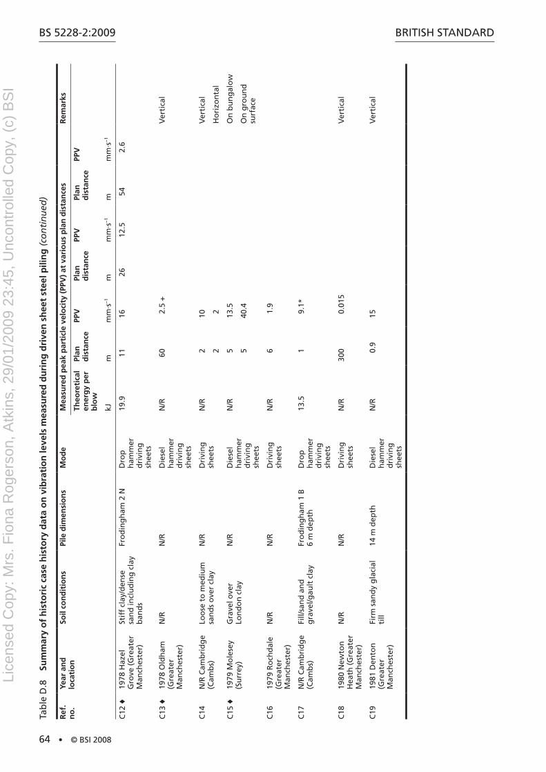
BS 5228-2:2009
64 • © BSI 2008
BritiSh Standard
Ref
. n
o.
Year
an
d
loca
tio
nSo
il co
nd
itio
ns
Pile
dim
ensi
on
sM
od
eM
easu
red
pea
k p
arti
cle
velo
city
(PP
V)
at v
ario
us
pla
n d
ista
nce
sR
emar
ks
Theo
reti
cal
ener
gy
per
b
low
Plan
d
ista
nce
PPV
Plan
d
ista
nce
PPV
Plan
d
ista
nce
PPV
kJm
mm
·s−
1m
mm
·s−
1m
mm
·s−
1
C12
♦19
78 h
azel
G
rove
(G
reat
er
Man
ches
ter)
Stif
f cl
ay/d
ense
sa
nd
incl
ud
ing
cla
y b
and
s
Fro
din
gh
am 2
nd
rop
h
amm
er
dri
vin
g
shee
ts
19.9
1116
2612
.554
2.6
C13
♦19
78 O
ldh
am
(Gre
ater
M
anch
este
r)
n/r
n/r
die
sel
ham
mer
d
rivi
ng
sh
eets
n/r
602.
5 +
Ver
tica
l
C14
n/r
Cam
bri
dg
e (C
amb
s)Lo
ose
to
med
ium
sa
nd
s o
ver
clay
n/r
dri
vin
g
shee
tsn
/r2
10V
erti
cal
22
ho
rizo
nta
l
C15
♦19
79 M
ole
sey
(Su
rrey
)G
rave
l ove
r Lo
nd
on
cla
yn
/rd
iese
l h
amm
er
dri
vin
g
shee
ts
n/r
513
.5O
n b
un
gal
ow
540
.4O
n g
rou
nd
su
rfac
e
C16
1979
ro
chd
ale
(Gre
ater
M
anch
este
r)
n/r
n/r
dri
vin
g
shee
tsn
/r6
1.9
C17
n/r
Cam
bri
dg
e (C
amb
s)Fi
ll/sa
nd
an
d
gra
vel/g
ault
cla
yFr
od
ing
ham
1 B
6
m d
epth
dro
p
ham
mer
d
rivi
ng
sh
eets
13.5
19.
1*
C18
1980
new
ton
h
eath
(G
reat
er
Man
ches
ter)
n/r
n/r
dri
vin
g
shee
tsn
/r30
00.
015
Ver
tica
l
C19
1981
den
ton
(G
reat
er
Man
ches
ter)
Firm
san
dy
gla
cial
ti
ll14
m d
epth
die
sel
ham
mer
d
rivi
ng
sh
eets
n/r
0.9
15V
erti
cal
tab
le d
.8
Sum
mar
y o
f h
isto
ric
case
his
tory
dat
a o
n v
ibra
tio
n le
vels
mea
sure
d d
uri
ng
dri
ven
sh
eet
stee
l pili
ng
(co
nti
nu
ed)
Lice
nsed
Cop
y: M
rs. F
iona
Rog
erso
n, A
tkin
s, 2
9/01
/200
9 23
:45,
Unc
ontr
olle
d C
opy,
(c)
BS
I
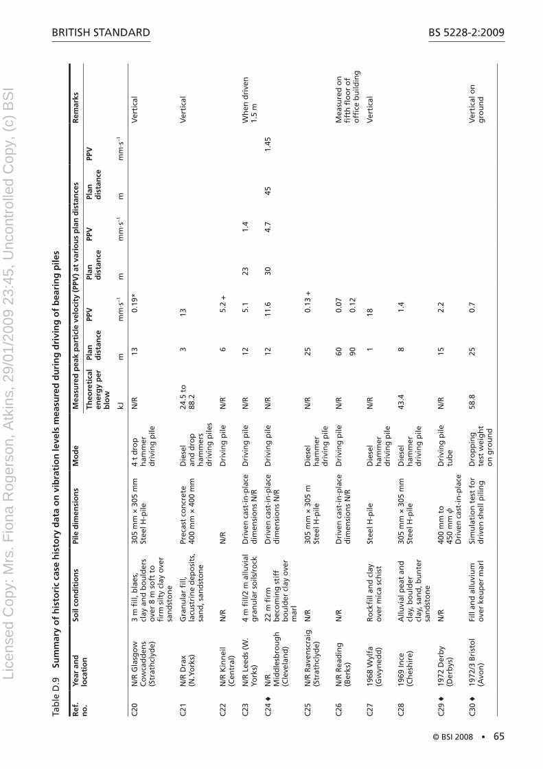
BritiSh Standard
© BSI 2008 • 65
BS 5228-2:2009
tab
le d
.9
Sum
mar
y o
f h
isto
ric
case
his
tory
dat
a o
n v
ibra
tio
n le
vels
mea
sure
d d
uri
ng
dri
vin
g o
f b
eari
ng
pile
s
Ref
. n
o.
Year
an
d
loca
tio
nSo
il co
nd
itio
ns
Pile
dim
ensi
on
sM
od
eM
easu
red
pea
k p
arti
cle
velo
city
(PP
V)
at v
ario
us
pla
n d
ista
nce
sR
emar
ks
Theo
reti
cal
ener
gy
per
b
low
Plan
d
ista
nce
PPV
Plan
d
ista
nce
PPV
Plan
d
ista
nce
PPV
kJm
mm
·s−
1m
mm
·s−
1m
mm
·s−
1
C20
n/r
Gla
sgo
w
Co
wca
dd
ens
(Str
ath
clyd
e)
3 m
fill,
bla
es,
clay
an
d b
ou
lder
s o
ver
8 m
so
ft t
o
firm
silt
y cl
ay o
ver
san
dst
on
e
305
mm
× 3
05 m
m
Stee
l h-p
ile4
t d
rop
h
amm
er
dri
vin
g p
ile
n/r
130.
19*
Ver
tica
l
C21
n/r
dra
x (n
.Yo
rks)
Gra
nu
lar
fill,
la
cust
rin
e d
epo
sits
, sa
nd
, san
dst
on
e
Prec
ast
con
cret
e 40
0 m
m ×
400
mm
die
sel
and
dro
p
ham
mer
s d
rivi
ng
pile
s
24.5
to
88
.23
13V
erti
cal
C22
n/r
Kin
nei
l (C
entr
al)
n/r
n/r
dri
vin
g p
ilen
/r6
5.2
+
C23
n/r
Lee
ds
(W.
York
s)4
m fi
ll/2
m a
lluvi
al
gra
nu
lar
soils
/ro
ckd
rive
n c
ast-
in-p
lace
d
imen
sio
ns
n/r
dri
vin
g p
ilen
/r12
5.1
231.
4W
hen
dri
ven
1.
5 m
C24
♦n
/r
Mid
dle
sbro
ug
h
(Cle
vela
nd
)
22 m
firm
b
eco
min
g s
tiff
b
ou
lder
cla
y o
ver
mar
l
dri
ven
cas
t-in
-pla
ce
dim
ensi
on
s n
/rd
rivi
ng
pile
n/r
1211
.630
4.7
451.
45
C25
n/r
rav
ensc
raig
(S
trat
hcl
yde)
n/r
305
mm
× 3
05 m
St
eel h
-pile
die
sel
ham
mer
d
rivi
ng
pile
n/r
250.
13 +
C26
n/r
rea
din
g
(Ber
ks)
n/r
dri
ven
cas
t-in
-pla
ce
dim
ensi
on
s n
/rd
rivi
ng
pile
n/r
600.
07M
easu
red
on
fi
fth
flo
or
of
offi
ce b
uild
ing
900.
12
C27
1968
Wyl
fa
(Gw
yned
d)
ro
ckfi
ll an
d c
lay
ove
r m
ica
sch
ist
Stee
l h-p
iled
iese
l h
amm
er
dri
vin
g p
ile
n/r
118
Ver
tica
l
C28
1969
ince
(C
hes
hir
e)a
lluvi
al p
eat
and
cl
ay, b
ou
lder
cl
ay, s
and
, bu
nte
r sa
nd
sto
ne
305
mm
× 3
05 m
m
Stee
l h-p
iled
iese
l h
amm
er
dri
vin
g p
ile
43.4
81.
4
C29
♦19
72 d
erb
y (d
erb
ys)
n/r
400
mm
to
45
0 m
m z
d
rive
n c
ast-
in-p
lace
dri
vin
g p
ile
tub
en
/r15
2.2
C30
♦19
72/3
Bri
sto
l (a
von
)Fi
ll an
d a
lluvi
um
o
ver
keu
per
mar
lSi
mu
lati
on
tes
t fo
r d
rive
n s
hel
l pili
ng
dro
pp
ing
te
st w
eig
ht
on
gro
un
d
58.8
250.
7V
erti
cal o
n
gro
un
d
Lice
nsed
Cop
y: M
rs. F
iona
Rog
erso
n, A
tkin
s, 2
9/01
/200
9 23
:45,
Unc
ontr
olle
d C
opy,
(c)
BS
I
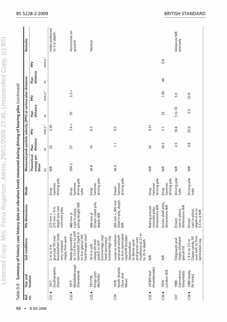
BS 5228-2:2009
66 • © BSI 2008
BritiSh Standard
Ref
. n
o.
Year
an
d
loca
tio
nSo
il co
nd
itio
ns
Pile
dim
ensi
on
sM
od
eM
easu
red
pea
k p
arti
cle
velo
city
(PP
V)
at v
ario
us
pla
n d
ista
nce
sR
emar
ks
Theo
reti
cal
ener
gy
per
b
low
Plan
d
ista
nce
PPV
Plan
d
ista
nce
PPV
Plan
d
ista
nce
PPV
kJm
mm
·s−
1m
mm
·s−
1m
mm
·s−
1
C31
♦19
77
Sou
tham
pto
n
(han
ts)
2 m
to
3 m
g
ran
ula
r fi
ll o
ver
bra
ckle
sham
bed
s,
very
co
mp
act
clay
ey fi
ne
san
d
275
mm
×
275
mm
× 9
m
dep
th p
re-c
ast
con
cret
e p
iles
dro
p
ham
mer
d
rivi
ng
pile
n/r
252.
45h
ole
s p
reb
ore
d
to 3
m d
epth
C32
♦19
77
Mid
dle
sbro
ug
h
(Cle
vela
nd
)
Mad
e g
rou
nd
/9 m
to
12
m fi
rm t
o s
tiff
la
min
ated
cla
y/4
m
to 6
m g
laci
al t
ill/
har
d k
eup
er m
arl
480
mm
z
Cas
t-in
-pla
ce,
pili
ng
len
gth
n/r
dro
p
ham
mer
d
rivi
ng
pile
tu
be
294.
227
7.4
+55
3.3
+h
ori
zon
tal o
n
gro
un
d
C33
♦19
77/7
8
Kin
gs
Lyn
n
(no
rfo
lk)
10.4
m s
oft
cl
ayey
silt
an
d
pea
t/5
m s
tiff
ki
mm
erid
ge
clay
/h
ard
lam
inat
ed
kim
mer
idg
e cl
ay
406
mm
z
dri
ven
cas
ed p
ile,
dep
th n
/r
dro
p
ham
mer
d
rivi
ng
pile
36.8
140.
3V
erti
cal
C34
1978
So
uth
Sh
ield
s (t
yne
and
W
ear)
Loo
se t
o m
ediu
m
san
d a
nd
silt
/so
ft
to fi
rm la
min
ated
cl
ay/s
tiff
bo
uld
er
clay
/med
ium
to
den
se s
and
an
d g
rave
l ove
r m
ud
sto
ne
at 2
1 m
to
25
m d
epth
305
mm
× 3
05 m
m
Stee
l h-p
ile, d
epth
n
/r
die
sel
ham
mer
d
rivi
ng
pile
36.3
1.1
9.5
C35
♦19
78/9
hu
ll (h
um
ber
sid
e)n
/rr
akin
g p
reca
st
con
cret
e p
iles,
d
imen
sio
ns
n/r
dro
p
ham
mer
d
rivi
ng
pile
n/r
200.
51
C36
♦19
79
Lon
do
n S
E8n
/rd
rive
n s
hel
l pile
s,
dim
ensi
on
s n
/rd
rop
h
amm
er
dri
vin
g p
ile
n/r
16.5
2.1
331.
9546
0.9
C37
1980
C
aern
arvo
n
(Gw
yned
d)
Fill/
gra
vels
an
d
clay
ey s
ilts/
har
d
gla
cial
till
dri
ven
ca
st-i
n-p
lace
, d
imen
sio
ns
n/r
dri
vin
g p
ile
tub
en
/r2.
518
.65
to 1
05.
5d
ista
nce
s n
/r
pre
cise
ly
C38
♦19
80 h
axb
y (n
.Yo
rks)
1.9
m t
o 3
.5 m
C
laye
y sa
nd
y fi
ll o
ver
soft
to
firm
la
min
ated
cla
y
dri
ven
ca
st-i
n-p
lace
, d
epth
4 m
to
5.
5 m
, z n
/r
dri
vin
g p
ile
tub
en
/r3.
825
.05.
522
.0
tab
le d
.9
Sum
mar
y o
f h
isto
ric
case
his
tory
dat
a o
n v
ibra
tio
n le
vels
mea
sure
d d
uri
ng
dri
vin
g o
f b
eari
ng
pile
s (c
on
tin
ued
)
Lice
nsed
Cop
y: M
rs. F
iona
Rog
erso
n, A
tkin
s, 2
9/01
/200
9 23
:45,
Unc
ontr
olle
d C
opy,
(c)
BS
I
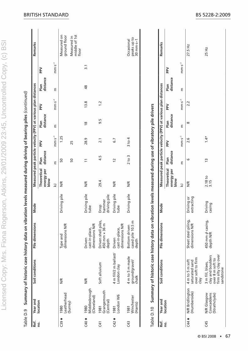
BritiSh Standard
© BSI 2008 • 67
BS 5228-2:2009
Ref
. n
o.
Year
an
d
loca
tio
nSo
il co
nd
itio
ns
Pile
dim
ensi
on
sM
od
eM
easu
red
pea
k p
arti
cle
velo
city
(PP
V)
at v
ario
us
pla
n d
ista
nce
sR
emar
ks
Theo
reti
cal
ener
gy
per
b
low
Plan
d
ista
nce
PPV
Plan
d
ista
nce
PPV
Plan
d
ista
nce
PPV
kJm
mm
·s−
1m
mm
·s−
1m
mm
·s−
1
C39
♦19
80
Leat
her
hea
d
(Su
rrey
)
n/r
typ
e an
d
dim
ensi
on
s n
/rd
rivi
ng
pile
n/r
501.
25M
easu
red
on
g
rou
nd
flo
or
5025
Mea
sure
d in
m
idd
le o
f 1s
t fl
oo
r
C40
♦19
80
Mid
dle
sbro
ug
h
(Cle
vela
nd
)
n/r
dri
ven
ca
st-i
n-p
lace
, d
imen
sio
ns
n/r
dri
vin
g p
ile
tub
en
/r11
28.9
1813
.848
3.1
C41
1981
G
ran
gem
ou
th
(Cen
tral
)
Soft
allu
viu
md
rive
n s
hel
l pile
s,
450
mm
× 3
6 m
d
epth
dro
p
ham
mer
d
rivi
ng
pile
29.4
4.5
2.1
9.5
1.2
C42
♦19
81
Lon
do
n W
64
m fi
ll/2
m b
alla
st/
Lon
do
n c
lay
dri
ven
ca
st-i
n-p
lace
, d
imen
sio
ns
n/r
dri
vin
g p
ile
tub
en
/r12
6.7
C43
1981
W
inch
este
r (h
ants
)
4 m
to
5 m
mad
e g
rou
nd
/gra
vel/
chal
k
Bo
tto
m d
rive
n
case
d p
ile 1
0.5
m
dep
th
dri
vin
g p
ilen
/r2
to 3
3 to
4O
ccas
ion
al
pea
ks u
p t
o
30 m
m·s
−1
tab
le d
.10
Sum
mar
y o
f h
isto
ric
case
his
tory
dat
a o
n v
ibra
tio
n le
vels
mea
sure
d d
uri
ng
use
of
vib
rato
ry p
ile d
rive
rs
Ref
. n
o.
Year
an
d
loca
tio
nSo
il co
nd
itio
ns
Pile
dim
ensi
on
sM
od
eM
easu
red
pea
k p
arti
cle
velo
city
(PP
V)
at v
ario
us
pla
n d
ista
nce
sR
emar
ks
Theo
reti
cal
ener
gy
per
b
low
Plan
d
ista
nce
PPV
Plan
d
ista
nce
PPV
Plan
d
ista
nce
PPV
kJm
mm
·s−
1m
mm
·s−
1m
mm
·s−
1
C44
♦n
/r B
rid
ling
ton
(h
um
ber
sid
e)4
m t
o 5
m s
oft
sa
tura
ted
san
d
ove
r so
ft t
o fi
rm
clay
Shee
t st
eel p
ilin
g,
dim
ensi
on
s n
/rd
rivi
ng
or
extr
acti
ng
n/r
62.
68
2.2
27.5
hz
C45
n/r
Gla
sgo
w
Co
wca
dd
ens
(Str
ath
clyd
e)
3 m
fill,
bla
es,
clay
an
d b
ou
lder
s o
ver
8 m
so
ft t
o
firm
silt
y cl
ay o
ver
san
dst
on
e
450
mm
z c
asin
g,
dep
th n
/rd
rivi
ng
ca
sin
g2.
18 t
o
3.15
131.
4*25
hz
tab
le d
.9
Sum
mar
y o
f h
isto
ric
case
his
tory
dat
a o
n v
ibra
tio
n le
vels
mea
sure
d d
uri
ng
dri
vin
g o
f b
eari
ng
pile
s (c
on
tin
ued
)
Lice
nsed
Cop
y: M
rs. F
iona
Rog
erso
n, A
tkin
s, 2
9/01
/200
9 23
:45,
Unc
ontr
olle
d C
opy,
(c)
BS
I
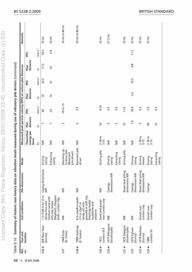
BS 5228-2:2009
68 • © BSI 2008
BritiSh Standard
Ref
. n
o.
Year
an
d
loca
tio
nSo
il co
nd
itio
ns
Pile
dim
ensi
on
sM
od
eM
easu
red
pea
k p
arti
cle
velo
city
(PP
V)
at v
ario
us
pla
n d
ista
nce
sR
emar
ks
Theo
reti
cal
ener
gy
per
b
low
Plan
d
ista
nce
PPV
Plan
d
ista
nce
PPV
Plan
d
ista
nce
PPV
kJm
mm
·s−
1m
mm
·s−
1m
mm
·s−
1
C46
♦n
/r n
ew h
aw
(Su
rrey
)1
m fi
ll/8
m t
o 1
2 m
d
ense
fin
e an
d
med
ium
san
d w
ith
si
lty
clay
len
ses
(Bag
sho
t), C
layg
ate
bed
s, L
on
do
n c
lay
Cas
ing
dim
ensi
on
s n
/rd
rivi
ng
ca
sin
gn
/r7
4410
23.5
17.5
18.5
25 h
z
Extr
acti
ng
ca
sin
gn
/r7
5315
2725
2.9
25 h
z
C47
1968
dra
x (n
. Yo
rks)
n/r
n/r
War
min
g u
p
to d
rive
pile
(r
eso
nan
t p
ile d
rive
r)
n/r
210
to
15
70 h
z to
80
hz
C48
♦19
68 h
asti
ng
s (E
. Su
ssex
)4
m c
lay/
8 m
pea
t/
2.5
m c
lay/
1 m
sa
nd
y si
lt w
ith
g
rave
l/6 m
sti
ff c
lay
(has
tin
gs
bed
s)/
mu
dst
on
e an
d
silt
sto
ne
n/r
res
on
ant
pile
d
rive
rn
/r6
2.5
70 h
z to
80
hz
C49
♦19
72
Lon
do
n E
C4
San
d a
nd
gra
vel
ove
r Lo
nd
on
cla
yn
/rd
rivi
ng
pile
2.18
to
3.
1510
0.55
25 h
z
C50
♦19
75 M
ilng
avie
(S
trat
hcl
yde)
n/r
Cas
ing
s,
dim
ensi
on
s n
/rd
rivi
ng
ca
sin
gn
/r5
2.5
27.5
hz
Extr
acti
ng
ca
sin
gn
/r5
2.0
C51
♦19
76 G
lasg
ow
(S
trat
hcl
yde)
n/r
Shee
t st
eel p
ilin
g,
dim
ensi
on
s n
/rd
rivi
ng
pile
n/r
1011
.025
hz
C52
1979
Eg
ham
(S
urr
ey)
n/r
Cas
ing
s,
dim
ensi
on
s n
/rd
rivi
ng
ca
sin
gn
/r1.
618
.93.
216
.34.
811
.225
hz
C53
♦19
79 M
ole
sey
(Su
rrey
)G
rave
l ove
r Lo
nd
on
cla
ySh
eet
stee
l pili
ng
, d
imen
sio
ns
n/r
dri
vin
g
shee
ts2.
18 t
o
3.15
54.
325
hz
C54
♦19
80
Lon
do
n n
1G
rave
l ove
r Lo
nd
on
cla
yC
asin
gs
dri
vin
g
casi
ng
2.18
to
3.
1540
2.0
25 h
z
Extr
acti
ng
ca
sin
g75
0.3
tab
le d
.10
Sum
mar
y o
f h
isto
ric
case
his
tory
dat
a o
n v
ibra
tio
n le
vels
mea
sure
d d
uri
ng
use
of
vib
rato
ry p
ile d
rive
rs (
con
tin
ued
)
Lice
nsed
Cop
y: M
rs. F
iona
Rog
erso
n, A
tkin
s, 2
9/01
/200
9 23
:45,
Unc
ontr
olle
d C
opy,
(c)
BS
I

BritiSh Standard
© BSI 2008 • 69
BS 5228-2:2009
Ref
. n
o.
Year
an
d
loca
tio
nSo
il co
nd
itio
ns
Pile
dim
ensi
on
sM
od
eM
easu
red
pea
k p
arti
cle
velo
city
(PP
V)
at v
ario
us
pla
n d
ista
nce
sR
emar
ks
Theo
reti
cal
ener
gy
per
b
low
Plan
d
ista
nce
PPV
Plan
d
ista
nce
PPV
Plan
d
ista
nce
PPV
kJm
mm
·s−
1m
mm
·s−
1m
mm
·s−
1
C55
1981
rh
on
dd
a V
alle
y (M
id
Gla
mo
rgan
)
Gla
cial
till
/ gra
velly
sa
nd
y si
lt m
ixtu
re
wit
h o
ccas
ion
al
cob
ble
s
Shee
t st
eel p
ilin
g,
Fro
din
gh
am 3
n
12 m
dep
th
dri
vin
g
shee
ts4.
8910
2.4
202.
240
0.8
Ver
tica
l 26.
6 h
z
C56
♦19
79 B
rom
ley
(Gre
ater
Lo
nd
on
)
Gra
vel
Shee
t st
eel p
ilin
gd
rivi
ng
sh
eets
n/r
342
93.
825
0.95
Var
iab
le
freq
uen
cy u
p
to 2
3.5
hz
tab
le d
.11
Sum
mar
y o
f m
isce
llan
eou
s h
isto
ric
case
his
tory
dat
a o
n v
ibra
tio
n le
vels
mea
sure
d d
uri
ng
pili
ng
an
d k
ind
red
op
erat
ion
s
Ref
. n
o.
Year
an
d
loca
tio
nSo
il co
nd
itio
ns
Pile
dim
ensi
on
sM
od
eM
easu
red
pea
k p
arti
cle
velo
city
(PP
V)
at v
ario
us
pla
n d
ista
nce
sR
emar
ks
Theo
reti
cal
ener
gy
per
b
low
Plan
d
ista
nce
PPV
Plan
d
ista
nce
PPV
Plan
d
ista
nce
PPV
kJm
mm
·s−
1m
mm
·s−
1m
mm
·s−
1
M1
c197
0
Lon
do
n W
C2
0.3
m fi
ll/0.
8 m
cla
y an
d g
rave
l/3.6
m
den
se s
and
an
d
gra
vel/s
tiff
Lo
nd
on
cl
ay in
clu
din
g c
lay
sto
nes
imp
act
bo
red
(t
rip
od
) p
ile
dim
ensi
on
s n
/r
dri
vin
g
casi
ng
4.25
2.7
3.1*
Mea
sure
d
at f
oo
tin
gs
adja
cen
t to
o
ld li
sted
ti
mb
er
fram
ed
bu
ildin
g
Bo
rin
g g
rave
l4.
252.
71.
0*4.
30.
6
M2
1971
Bri
sto
l (a
von
)So
ft c
lays
ove
r sa
nd
sto
ne/
mar
l at
10
m t
o 1
1 m
d
epth
dri
ven
ste
el h
-pile
s 30
5 m
m ×
305
mm
×
12
m d
epth
dro
p
ham
mer
d
rivi
ng
pile
s
35.7
1.5
68.4
*3
50.2
*4.
637
.7*
4 t
ham
mer
0.
9 m
dro
p,
3 t
ham
mer
1.
2 m
dro
p,
all g
rou
nd
su
rfac
e m
easu
rem
ents
35.7
1.5
48.8
*3
39.4
*4.
620
.6*
M3
1971
Ste
ven
age
(her
ts)
Med
ium
den
se
san
ds
and
gra
vels
Bo
tto
m d
rive
n
cast
-in
-pla
ce p
ilin
gd
rop
h
amm
er
dri
vin
g p
ile
tub
e
127
311
6*6.
130
.3*
9.1
25.1
*G
rou
nd
su
rfac
e m
easu
rem
ents
tab
le d
.10
Sum
mar
y o
f h
isto
ric
case
his
tory
dat
a o
n v
ibra
tio
n le
vels
mea
sure
d d
uri
ng
use
of
vib
rato
ry p
ile d
rive
rs (
con
tin
ued
)
Lice
nsed
Cop
y: M
rs. F
iona
Rog
erso
n, A
tkin
s, 2
9/01
/200
9 23
:45,
Unc
ontr
olle
d C
opy,
(c)
BS
I
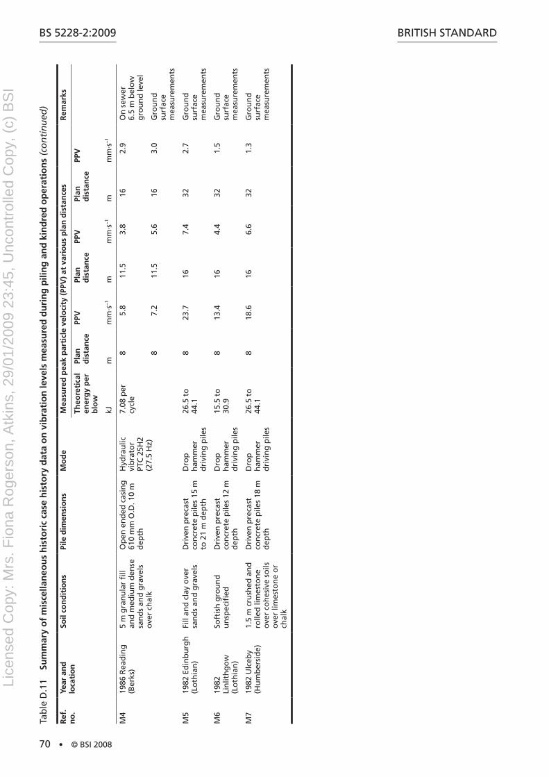
BS 5228-2:2009
70 • © BSI 2008
BritiSh Standard
Ref
. n
o.
Year
an
d
loca
tio
nSo
il co
nd
itio
ns
Pile
dim
ensi
on
sM
od
eM
easu
red
pea
k p
arti
cle
velo
city
(PP
V)
at v
ario
us
pla
n d
ista
nce
sR
emar
ks
Theo
reti
cal
ener
gy
per
b
low
Plan
d
ista
nce
PPV
Plan
d
ista
nce
PPV
Plan
d
ista
nce
PPV
kJm
mm
·s−
1m
mm
·s−
1m
mm
·s−
1
M4
1986
rea
din
g
(Ber
ks)
5 m
gra
nu
lar
fill
and
med
ium
den
se
san
ds
and
gra
vels
o
ver
chal
k
Op
en e
nd
ed c
asin
g
610
mm
O.d
. 10
m
dep
th
hyd
rau
lic
vib
rato
r
PtC
25h
2 (2
7.5
hz)
7.08
per
cy
cle
85.
811
.53.
816
2.9
On
sew
er
6.5
m b
elo
w
gro
un
d le
vel
87.
211
.55.
616
3.0
Gro
un
d
surf
ace
mea
sure
men
ts
M5
1982
Ed
inb
urg
h
(Lo
thia
n)
Fill
and
cla
y o
ver
san
ds
and
gra
vels
dri
ven
pre
cast
co
ncr
ete
pile
s 15
m
to 2
1 m
dep
th
dro
p
ham
mer
d
rivi
ng
pile
s
26.5
to
44
.18
23.7
167.
432
2.7
Gro
un
d
surf
ace
mea
sure
men
ts
M6
1982
Li
nlit
hg
ow
(L
oth
ian
)
Soft
ish
gro
un
d
un
spec
ified
dri
ven
pre
cast
co
ncr
ete
pile
s 12
m
dep
th
dro
p
ham
mer
d
rivi
ng
pile
s
15.5
to
30
.98
13.4
164.
432
1.5
Gro
un
d
surf
ace
mea
sure
men
ts
M7
1982
Ulc
eby
(hu
mb
ersi
de)
1.5
m c
rush
ed a
nd
ro
lled
lim
esto
ne
ove
r co
hes
ive
soils
o
ver
limes
ton
e o
r ch
alk
dri
ven
pre
cast
co
ncr
ete
pile
s 18
m
dep
th
dro
p
ham
mer
d
rivi
ng
pile
s
26.5
to
44
.18
18.6
166.
632
1.3
Gro
un
d
surf
ace
mea
sure
men
ts
tab
le d
.11
Sum
mar
y o
f m
isce
llan
eou
s h
isto
ric
case
his
tory
dat
a o
n v
ibra
tio
n le
vels
mea
sure
d d
uri
ng
pili
ng
an
d k
ind
red
op
erat
ion
s (c
on
tin
ued
)
Lice
nsed
Cop
y: M
rs. F
iona
Rog
erso
n, A
tkin
s, 2
9/01
/200
9 23
:45,
Unc
ontr
olle
d C
opy,
(c)
BS
I
BritiSh Standard
© BSI 2008 • 71
BS 5228-2:2009
Annex E (informative) Prediction of vibration levels
E.1 Prediction of vibration levels from construction activitieshiller and Crabb [11] have derived empirical formulae relating resultant PPV with a number of other parameters for vibratory compaction, percussive and vibratory piling, dynamic compaction, the vibration of stone columns and tunnel boring operations (the latter also providing a groundborne noise predictor) from field measurements.
these predictions for a variety of scaling factors and parameter ranges are reproduced in table E.1.
NOTE Tables E.1 and E.2 are reproduced with the permission of TRL Limited. Copyright Transport Research Laboratory 2000.
Use of these formulae enables a prediction to be made of resultant peak particle velocities (PPV) and, for some processes, can provide an indicator of the probability of these figures being exceeded.
Lice
nsed
Cop
y: M
rs. F
iona
Rog
erso
n, A
tkin
s, 2
9/01
/200
9 23
:45,
Unc
ontr
olle
d C
opy,
(c)
BS
I

BS 5228-2:2009
72 • © BSI 2008
BritiSh Standardta
ble
E.1
Em
pir
ical
pre
dic
tors
fo
r g
rou
nd
bo
rne
vib
rati
on
ari
sin
g f
rom
mec
han
ized
co
nst
ruct
ion
wo
rks
Op
erat
ion
Pred
icti
on
qu
esti
on
Scal
ing
fac
tors
(an
d p
rob
abili
ty o
f p
red
icte
d v
alu
e b
ein
g e
xcee
ded
)Pa
ram
eter
ran
ge
Vib
rato
ry c
om
pac
tio
n (
stea
dy
stat
e)ν re
ss
dd
=+
kn
Ax
L
15.
k s =
75
(50%
) k s
= 1
43 (
33.3
%)
k s =
276
(5%
)
1 G
nd G
2
0.4 G
a G
1.7
2 m
m
2 G
x G
110
m
Vib
rato
ry c
om
pac
tio
n (
star
t u
p a
nd
ru
n d
ow
n)
ν res
td
d
=+
k
nA
xL1
5
13
.
.(
)
k t =
65
(50%
) k t
= 1
06 (
33.3
%)
k t =
177
(5%
)
0.75
G L
d G
2.2
m
Perc
uss
ive
pili
ng
ν res
p
kW r1
3.
For
pile
s at
ref
usa
l: k p
= 5
Fo
r p
iles
no
t at
ref
usa
l: 1 G
kp G
3,
dep
end
ing
on
so
il ty
pe
(tab
le E
.2)
1 G
L G
27
m
1 G
x G
111
m (
wh
ere
r2 = L
2 + x
2 ) 1.
5 G
W G
85
kJ
Vib
rato
ry p
ilin
gν
δre
sv
=k x
k v =
60
(50%
) k v
= 1
26 (
33.3
%)
k v =
266
(5%
)
1 G
x G
100
m
1.2 G
W G
10.
7 kJ
d
= 1
.3 (
all o
per
atio
ns)
d
= 1
.2 (
star
t u
p a
nd
ru
n d
ow
n)
d =
1.4
(st
ead
y st
ate
op
erat
ion
)
dyn
amic
co
mp
acti
on
ν res
h
003
7
17
.
.
W x
5 G
x G
100
m
1.0 G
Wh G
12
MJ
Vib
rate
d s
ton
e co
lum
ns
ν res
c=
k x14.
k c =
33
(50%
) k c
= 4
4 (3
3.3%
) k c
= 9
5 (5
%)
8 G
x G
100
m
tun
nel
ling
(g
rou
nd
bo
rne
vib
rati
on
)ν re
s
180
13
x.
10 G
r G
100
m
tun
nel
ling
(g
rou
nd
bo
rne
no
ise)
Lr
p=
−12
754
10lo
g10
G r
G 1
00 m
A
max
imu
m a
mp
litu
de
of
dru
m v
ibra
tio
n, i
n m
illim
etre
s (m
m)
L p
ile t
oe
dep
th, i
n m
etre
s (m
)
L d
vib
rati
ng
ro
ller
dru
m w
idth
, in
met
res
(m)
L p
roo
m o
ctav
e b
and
so
un
d p
ress
ure
leve
l, in
dec
ibel
s (d
B)
nd
nu
mb
er o
f vi
bra
tin
g d
rum
s
r sl
op
e d
ista
nce
fro
m t
he
pile
to
e, in
met
res
(m)
ν res
c=
k x14.
re
sult
ant
PPV,
in m
illim
etre
s p
er s
eco
nd
(m
m·s
−1 )
W
no
min
al h
amm
er e
ner
gy,
in jo
ule
s (J
)
Wc
ener
gy
per
cyc
le, i
n k
ilojo
ule
s (k
J)
Wh
po
ten
tial
en
erg
y o
f a
rais
ed t
amp
er, i
n jo
ule
s (J
)
x d
ista
nce
mea
sure
d a
lon
g t
he
gro
un
d s
urf
ace,
in m
etre
s (m
)
Lice
nsed
Cop
y: M
rs. F
iona
Rog
erso
n, A
tkin
s, 2
9/01
/200
9 23
:45,
Unc
ontr
olle
d C
opy,
(c)
BS
I
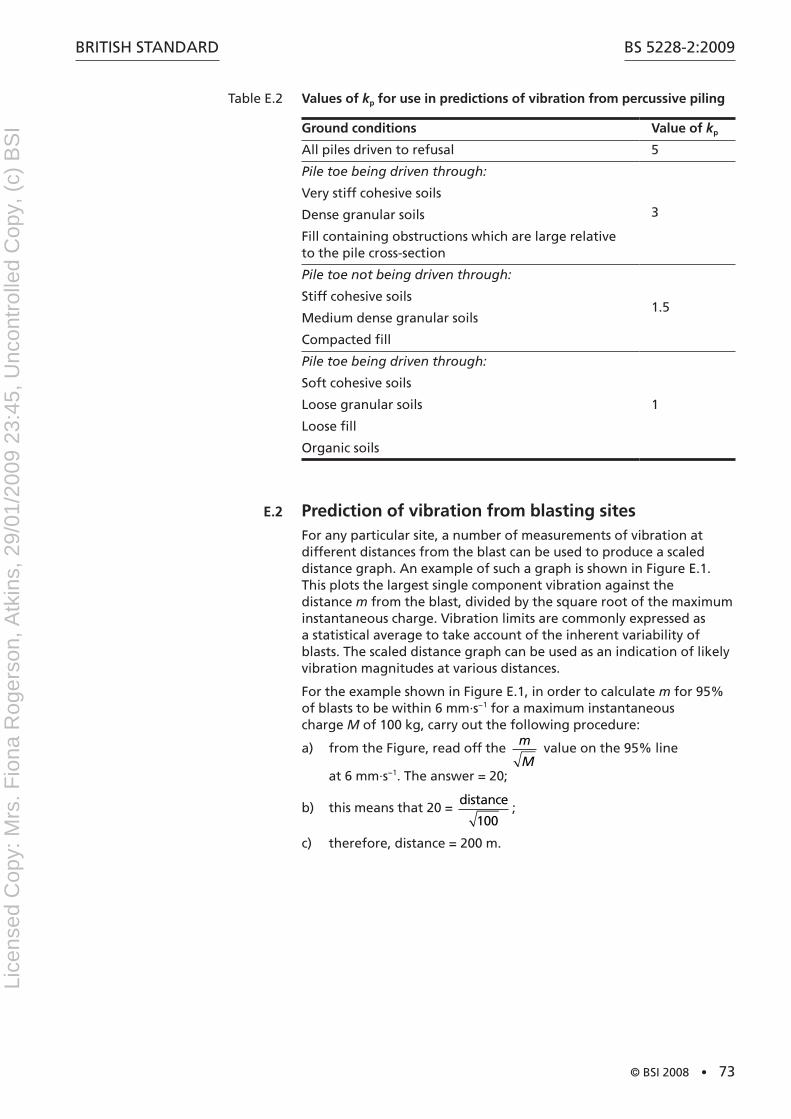
BritiSh Standard
© BSI 2008 • 73
BS 5228-2:2009
table E.2 Values of kp for use in predictions of vibration from percussive piling
Ground conditions Value of kp
all piles driven to refusal 5
Pile toe being driven through:
3Very stiff cohesive soils
dense granular soils
Fill containing obstructions which are large relative to the pile cross-section
Pile toe not being driven through:
1.5Stiff cohesive soils
Medium dense granular soils
Compacted fill
Pile toe being driven through:
1
Soft cohesive soils
Loose granular soils
Loose fill
Organic soils
E.2 Prediction of vibration from blasting sitesFor any particular site, a number of measurements of vibration at different distances from the blast can be used to produce a scaled distance graph. an example of such a graph is shown in Figure E.1. this plots the largest single component vibration against the distance m from the blast, divided by the square root of the maximum instantaneous charge. Vibration limits are commonly expressed as a statistical average to take account of the inherent variability of blasts. the scaled distance graph can be used as an indication of likely vibration magnitudes at various distances.
For the example shown in Figure E.1, in order to calculate m for 95% of blasts to be within 6 mm·s−1 for a maximum instantaneous charge M of 100 kg, carry out the following procedure:
from the Figure, read off the a) m
M value on the 95% line
at 6 mm·s−1. the answer = 20;
this means that 20 = b) distance
100;
therefore, distance = 200 m.c)
Lice
nsed
Cop
y: M
rs. F
iona
Rog
erso
n, A
tkin
s, 2
9/01
/200
9 23
:45,
Unc
ontr
olle
d C
opy,
(c)
BS
I
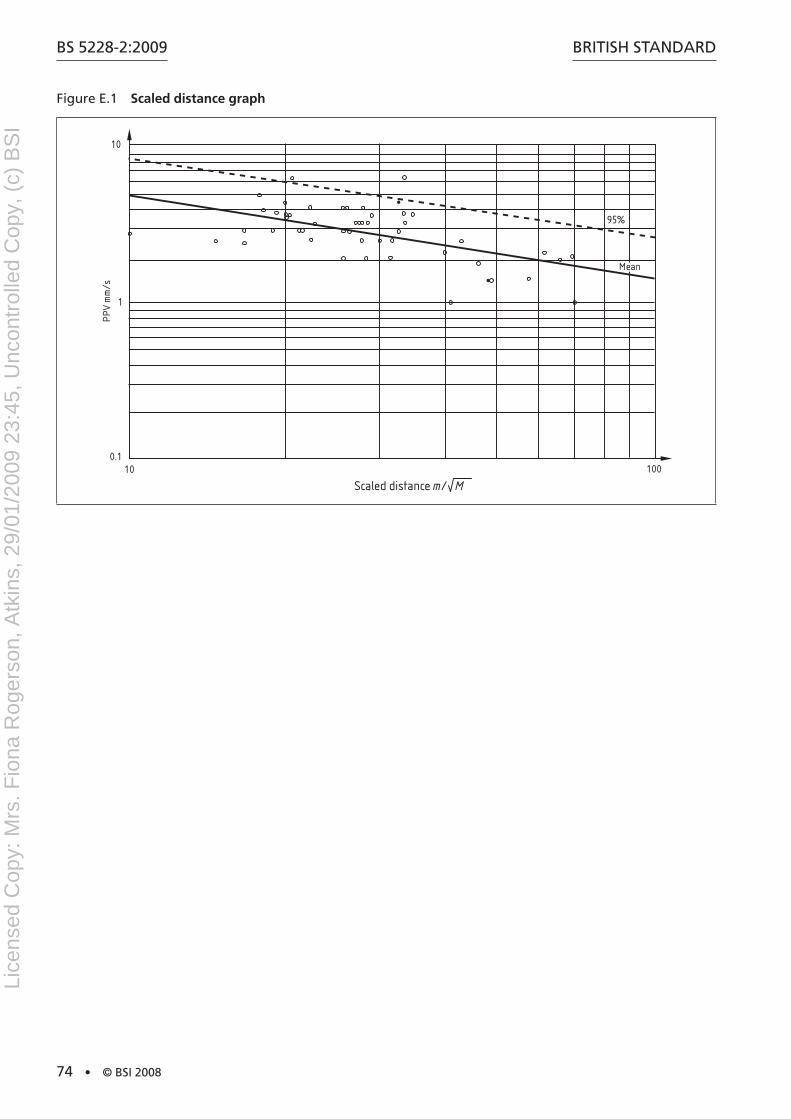
BS 5228-2:2009
74 • © BSI 2008
BritiSh Standard
Figure E.1 Scaled distance graph
10
1
0.110 100
95%
Mean
PPV
mm
/s
Scaled distance m/ M
Lice
nsed
Cop
y: M
rs. F
iona
Rog
erso
n, A
tkin
s, 2
9/01
/200
9 23
:45,
Unc
ontr
olle
d C
opy,
(c)
BS
I
BritiSh Standard
© BSI 2008 • 75
BS 5228-2:2009
Annex F (informative) Description of vibrationNOTE F.1 to F.3 relate primarily, but not exclusively, to piling and kindred activities, and F.4 to F.6 relate primarily to surface mineral extraction
F.1 Types of vibrationVibrations can be categorized in several ways as follows:
continuous vibrations in which the cyclic variation in amplitude is a) repeated many times;
transient vibrations in which the cyclic variation in amplitude b) reaches a peak and then decays away towards zero relatively quickly;
intermittent vibrations in which a sequence (sometimes regular, c) sometimes irregular) of transient vibrations occurs, but with sufficient intervals between successive events to permit the amplitude to diminish to an insignificant level in the interim periods.
Examples of these types of vibration within the piling field are:
continuous vibrations from a vibrating pile driver;1)
transient vibrations from an isolated hammer blow;2)
intermittent vibrations from a drop hammer pile driver.3)
the response of soil and structures to continuous vibrations is to vibrate in sympathy with the vibrating source, i.e. at the same frequency or harmonics thereof. the resulting vibrations are, therefore, known as forced vibrations. impulsive shocks giving rise to transient vibrations, on the other hand, excite the natural frequencies of the soil-structure combination and thus the resulting vibrations are known as free vibrations.
F.2 Characteristics of vibrationVibrations are physically characterized as wave phenomena. they can be transmitted in one or more wave types, the most common of which are compression, shear and rayleigh (or surface) waves. Each type of wave travels at a velocity which is characteristic of the material properties of the medium through which it is propagated. the wave velocity determines the time lag between the event at the source, e.g. the pile position and the remote receiving point. it does not, however, determine the severity of the vibration response at the remote receiving point, although the material properties of the transmitting medium play a significant role in this.
as the wave passes through the receiving point, the particles of matter undergo a vibratory or oscillatory motion. it is the intensity of these oscillatory particle motions which determine the vibration response at the receiving point.
NOTE Some air‑operated hammers have sufficiently rapid striking rates to prevent the amplitude of vibration diminishing to an insignificant level between successive events (or impacts). In spite of the impulsive nature of the wave form the resulting vibrations can be described as continuous.
Lice
nsed
Cop
y: M
rs. F
iona
Rog
erso
n, A
tkin
s, 2
9/01
/200
9 23
:45,
Unc
ontr
olle
d C
opy,
(c)
BS
I
BS 5228-2:2009
76 • © BSI 2008
BritiSh Standard
the oscillatory motion can be characterized physically in terms of the following:
a displacement about the mean value a) A;
a particle velocity b) v;
an acceleration c) a;
frequency of the disturbance ƒ.d)
in the case of sinusoidal wave propagation these parameters are simply related by the formulae:
v = 2πƒA
a = 4π2ƒ2A = 2πƒv
where the symbols are each assigned their peak values.
it is not normally practicable to measure all four parameters simultaneously and indeed this is not generally necessary, since for the majority of frequencies of interest in piling operations the PPV is the best indicator of the vibratory response, especially when it is combined with the frequency content of the disturbance. Further guidance on human response to vibrations is given in BS 6472.
F.3 Vibrations associated with specific operations
F.3.1 Intermittent and transient vibrations
F.3.1.1 Single-acting pile hammers
intermittent vibrations are obtained with most single-acting pile hammers. a variety of mechanisms can be used to raise the hammer after each blow, e.g. winch rope, diesel, hydraulic or compressed air.
Some diesel and air hammers are double acting and have considerably more rapid striking (or repetition) rates than conventional free fall hammers. this can result in vibrations being set up in certain circumstances (see note to F.1).
F.3.1.2 Impact bored piling
traditional impact bored piling gives rise to intermittent vibrations, both in the boring process when the boring tool is allowed to fall freely to form the borehole, and also when temporary casing is being driven or extracted.
F.3.1.3 Rotary bored piling
although rotary bored piling tends to set up low level vibrations, transient vibrations can also occur when the auger strikes the base of the borehole. if it is necessary to insert an appreciable length of temporary casing to support the boring, a casing dolly can be used and, as with the impact bored piling method, this will give rise to intermittent vibrations. the use of special tools, such as chisels, will also result in intermittent vibrations.
Lice
nsed
Cop
y: M
rs. F
iona
Rog
erso
n, A
tkin
s, 2
9/01
/200
9 23
:45,
Unc
ontr
olle
d C
opy,
(c)
BS
I
BritiSh Standard
© BSI 2008 • 77
BS 5228-2:2009
F.3.1.4 Clamshell grabs
the construction of diaphragm walls and barrettes using clamshell grabs can give rise to transient or intermittent vibrations. the grabs can be operated either hydraulically, or by rope, but in each case they impact (with open jaws) on the soil in the trench. Since the excavation is filled with a bentonite suspension for temporary support there will be a modest buoyancy factor.
F.3.1.5 Free falling tamping weights
Ground treatment by dynamic compaction using large free falling tamping weights results in intermittent vibrations. the process is generally carried out on large sites to improve the density of relatively loose soils or fill materials. the major frequency content of the free vibrations tends to be very low.
F.3.1.6 Other operations causing intermittent vibrations
the formation of stone columns using plant designed for driven cast-in-place piling is another source of intermittent vibrations.
F.3.2 Continuous vibrations
F.3.2.1 General
Continuous vibrations differ from intermittent or transient vibrations in that the vibratory stimulus is maintained through a sequence of cycles. if the frequency of the vibrations coincides with a natural frequency of, for example, a structural element, then resonance can be induced. the resulting vibrations then exhibit substantially higher amplitudes than otherwise would be the case. this needs to be borne in mind if the criteria recommended in annex B are used for the setting of acceptable limits for vibrations at the remote receiving point.
Continuous vibrations are associated primarily with vibratory pile drivers and vibratory compaction plant. Vibratory pile drivers are used for installing or extracting steel sheet and h-section piles and temporary or permanent casings for bored piles. Small vibrators are used for inserting reinforcement cages in continuous flight auger injected piles, and during the extraction of the driving tube following the concreting of a driven cast-in-place pile. the vibration in this latter case assists in compacting the concrete in the pile shaft, and the technique is employed as an alternative to hammering the tube during its extraction. Vibratory compaction plant is available in a wide range of sizes, for use in activities from reinstatement of excavated trenches to major earthworks construction.
F.3.2.2 Vibratory pile drivers
Vibratory pile drivers can be very effective in loose to medium, cohesionless or weakly cohesive soils. the continuous vibration of the pile member effectively fluidizes the immediately surrounding soil, removing contact friction during a fraction of each vibration cycle. the mechanism is thwarted in dense cohesionless soils and stiff cohesive soils, and a vibrator used at length under these circumstances merely succeeds in increasing the level of environmental vibrations at the expense of very slow penetration, especially with displacement piles.
NOTE See Table E.1 for variables that determine the intensity of vibration from sources of continuous vibrations.
Lice
nsed
Cop
y: M
rs. F
iona
Rog
erso
n, A
tkin
s, 2
9/01
/200
9 23
:45,
Unc
ontr
olle
d C
opy,
(c)
BS
I
BS 5228-2:2009
78 • © BSI 2008
BritiSh Standard
Most vibratory pile drivers derive their cyclic axial motion from one or more pairs of horizontally opposed contra-rotating eccentric weights, which can be powered hydraulically or electrically. the design operating frequency of these vibrators is typically in the range 25 hz to 30 hz, which is rather higher than natural frequencies associated with loose or medium loose soil sites. this can lead to a high and possibly dangerous (although short-lived) response at the remote receiving station whenever the vibrator is switched on or off, as it accelerates or decelerates through the range either of site frequencies or of the natural frequencies of floor slabs, etc.
the introduction of variable moment resonance-free vibrators, as described in 8.5.3.10, has enabled this unwanted effect to be minimized.
NOTE 1 As a guide, whole building response for buildings up to four storeys in height, as opposed to building element response, generally occurs at frequencies between 5 Hz and 15 Hz. Buildings element response, e.g. slabs, can occur at frequencies between 5 Hz and 40 Hz. For buildings more than four storeys in height, the whole building response frequency is likely to be less than 5 Hz to 12 Hz.
NOTE 2 Care is needed when using vibrators with frequencies less than 25 Hz.
F.3.2.3 Resonant pile drivers
a similar principle to that for vibratory pile drivers applies to very high frequency resonant pile drivers. in this case the vibrator is capable of oscillating at high frequencies (up to 135 hz) and is designed to tune to one of the natural modes of vibration of the pile being driven, in order to obtain the benefits of pile resonance.
F.3.2.4 Continuous flight auger injected piling and pressed-in piling
the levels of vibration associated with continuous flight auger injected piling and pressed-in piling are minimal, as the processes do not involve rapid acceleration or deceleration of tools in contact with the ground but rely to a large extent on steady motions. Continuous vibrations at a low level could be expected from the prime movers.
F.3.2.5 Vibroflotation and vibroreplacement
in ground treatment processes by vibroflotation or vibroreplacement, a rotating eccentric weight in the nose of the machine sets up a mainly horizontal vibration pattern. this is basically a much enlarged version of the familiar vibrating poker used for compacting concrete. Pokers for vibroflotation are generally energized by electric or hydraulic motors and typically operate at frequencies between 30 hz and 50 hz.
F.3.2.6 Vibrating lances
another ground treatment process is the installation of vertical band drains. this can be achieved by using a vibrating lance. the vibrator is similar in concept to, but somewhat smaller than, vibrators used for pile driving.
Lice
nsed
Cop
y: M
rs. F
iona
Rog
erso
n, A
tkin
s, 2
9/01
/200
9 23
:45,
Unc
ontr
olle
d C
opy,
(c)
BS
I
BritiSh Standard
© BSI 2008 • 79
BS 5228-2:2009
F.3.2.7 Other operations causing continuous vibrations
Continuous vibrations, albeit at low intensities, can be experienced from diesel engines, e.g. from impact bored piling winches mounted on skids, crawler mounted base machines, and attendant plant.
F.4 Ground vibration from surface mineral extractionthe primary cause of ground vibration on surface mineral extraction sites is blasting.
the level of vibration depends upon the distance from the blast, the maximum instantaneous charge weight of explosive, the delay sequencing and the geological nature and structure between the blast and receiver.
Other processes such as block making can give rise locally to ground vibration.
F.5 CriteriaBS 7385-1 gives information on the methodology for measurement, data analysis, reporting and building classification.
BS 7385-2 gives guidance on the assessment of the possibility of vibration-induced damage in buildings due to a variety of sources. this guidance indicates that the probability of damage tends towards zero at a component PPV of 12.5 mm·s−1.
BS 6472 provides guidance on human response to vibration. Guidance is given on the magnitudes of vibration at which adverse comment might begin to arise. advice is given on vibration measurement, factors which influence human response and satisfactory vibration magnitudes.
annex a of Minerals Planning Guidance note MPG 9 [12] and Scottish Government Circular 26/1992 [58] give illustrative guides to the planning conditions on vibration limits. these state that:
“ground vibration as a result of blasting operations shall not exceed a peak particle velocity of [6 mm/sec] [10 mm/sec] in 95% of all blasts measured over any period of [six months] and no individual blast shall exceed a peak particle velocity of [12 mm/sec] as measured at vibration sensitive buildings. the measurement to be the maximum of three mutually perpendicular directions taken at the ground surface.”
this indicates that the statistical limit should be chosen, for example, between 6 mm·s−1 and 10 mm·s−1 and that the maximum value should not normally exceed 12 mm·s−1.
Further information is given in BrE digest 403 [55].
F.6 Measurement of vibrationVibration from blasting can be measured with seismograph equipment, with geophones or with accelerometers.
the PPV in millimetres per second can be measured in three orthogonal axes at a point on the ground or inside a property. Figure F.1 shows a two-storey building neighbouring a quarry with possible measurement locations indicated. the difference between vibration levels on the ground and inside a property can be illustrated as follows.
Lice
nsed
Cop
y: M
rs. F
iona
Rog
erso
n, A
tkin
s, 2
9/01
/200
9 23
:45,
Unc
ontr
olle
d C
opy,
(c)
BS
I
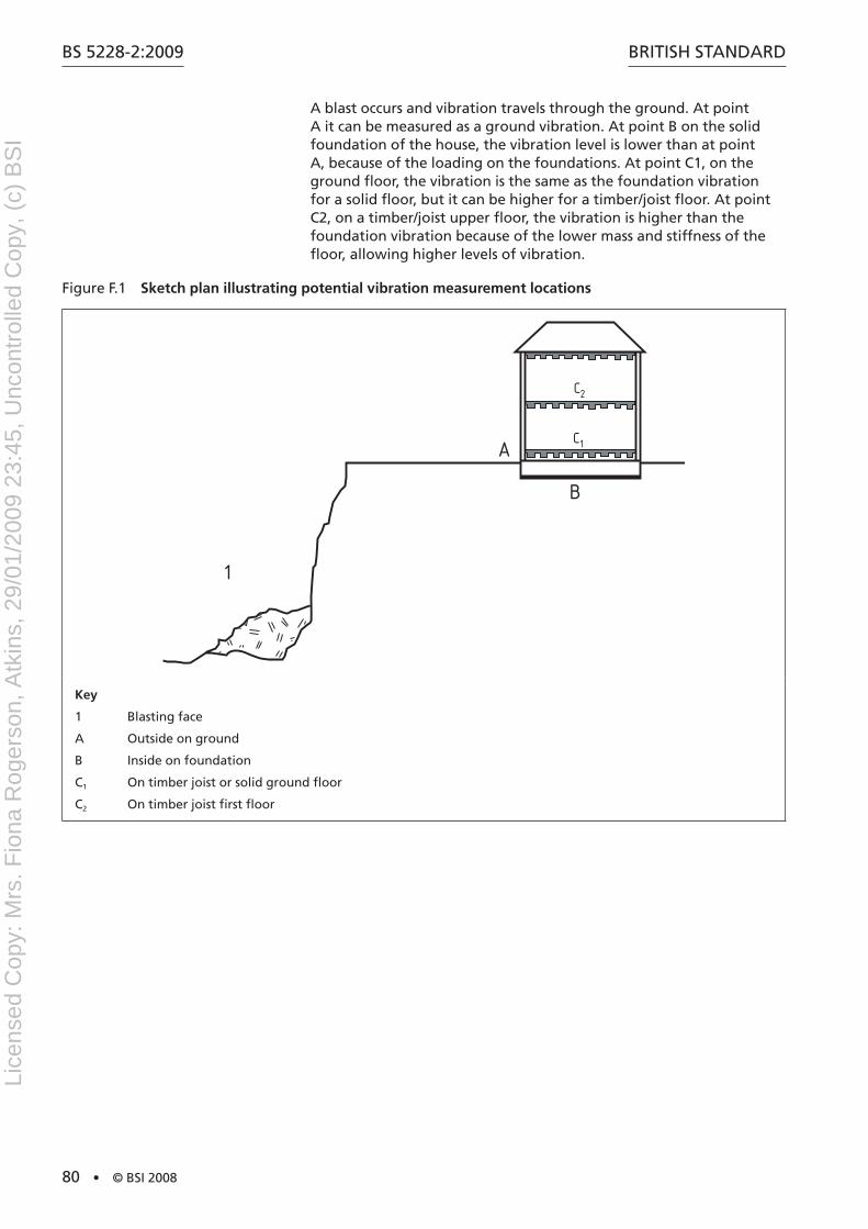
BS 5228-2:2009
80 • © BSI 2008
BritiSh Standard
a blast occurs and vibration travels through the ground. at point a it can be measured as a ground vibration. at point B on the solid foundation of the house, the vibration level is lower than at point a, because of the loading on the foundations. at point C1, on the ground floor, the vibration is the same as the foundation vibration for a solid floor, but it can be higher for a timber/joist floor. at point C2, on a timber/joist upper floor, the vibration is higher than the foundation vibration because of the lower mass and stiffness of the floor, allowing higher levels of vibration.
Figure F.1 Sketch plan illustrating potential vibration measurement locations
C2
C1
1
A
B
Key
1 Blasting face
a Outside on ground
B inside on foundation
C1 On timber joist or solid ground floor
C2 On timber joist first floor
Lice
nsed
Cop
y: M
rs. F
iona
Rog
erso
n, A
tkin
s, 2
9/01
/200
9 23
:45,
Unc
ontr
olle
d C
opy,
(c)
BS
I
BritiSh Standard
© BSI 2008 • 81
BS 5228-2:2009
Annex G (informative) Air overpressure
G.1 DescriptionWhenever blasting is carried out, energy is transmitted from the blast site in the form of airborne pressure waves. these pressure waves comprise energy over a wide range of frequencies, some of which are higher than 20 hz and therefore perceptible as sound, whereas the majority are below 20 hz and hence inaudible, but can be sensed as concussion. it is the combination of the sound and concussion that is known as air overpressure.
the attenuation effects due to the topography, either natural or manufactured, between the blast and the receiver are much greater on the audible component of the pressure wave, whereas the effects are relatively slight on the lower frequency concussive component. the energy transmitted in the audible part of the pressure wave is much smaller than that in the concussive part and therefore baffle mounds or other acoustic screening techniques do not significantly reduce the overall air overpressure intensity.
air overpressure can excite secondary vibrations at an audible frequency in buildings and it is usually this effect which has been found to give rise to comment from occupants. there is no known evidence of structural damage to structures from excessive air overpressure levels from quarry blasting.
Meteorological conditions, over which an operator has no control, such as temperature, cloud cover, humidity, wind speed, turbulence and direction, all affect the intensity of air overpressure at any location and cannot be reliably predicted. these conditions vary in time and position and therefore the reduction in air overpressure values as the distance from the blast increases might be greater in some directions than others.
G.2 Sources of blast-generated air overpressurethe use of detonating cord, inadequate or poor stemming and gas venting are major sources of air overpressure and can be controlled with good blast design. Sufficient stemming with appropriate material such as sized stone chippings is necessary. Gas venting can be minimized by good blast design, accurate drilling and careful placement of the correct amount of explosives. the other major sources of air overpressure from blasting are the reflection of stresses from a free face of an unbroken rock mass and also from the physical movement of a rock mass around the shot holes and at other free faces.
detailed requirements for the use of explosives at quarries are contained in the Quarries (Explosives) regulations 1988 [59] and the Quarries (Explosives) regulations (northern ireland) 2006 [60].
G.3 Criteriaas the airborne pressure waves pass any single point the pressure of the air rises rapidly to a value above atmospheric pressure, falls to below atmospheric pressure, then returns to normal pressure after a series of oscillations. the maximum value above atmospheric pressure is known as peak air overpressure and is measured in pressure terms and generally expressed in linear decibels (dB lin) (see G.4).
Lice
nsed
Cop
y: M
rs. F
iona
Rog
erso
n, A
tkin
s, 2
9/01
/200
9 23
:45,
Unc
ontr
olle
d C
opy,
(c)
BS
I
BS 5228-2:2009
82 • © BSI 2008
BritiSh Standard
routine blasting can regularly generate air overpressure levels at adjacent premises of around 120 dB (lin). this level corresponds to an excess air pressure which is equivalent to that of a steady wind velocity of 5 m·s−1 (Beaufort force 3, gentle breeze) and is likely to be above the threshold of perception.
Windows are generally the weakest parts of a structure, and research by the United States Bureau of Mines [61] has shown that a poorly mounted window that is prestressed might crack at 150 dB (lin), with most windows cracking at around 170 dB (lin), whereas structural damage would not be expected at levels below 180 dB (lin).
G.4 MeasurementMeasurement of air overpressure needs to be undertaken with microphones with an adequate low frequency response to fully capture the dominant low frequency component. a 2 hz high pass system has been found to be satisfactory. Most of the equipment more commonly used for noise measurement is therefore not suitable for measuring overpressure. although monitoring of air overpressure can be undertaken, due to the uncertainties with meteorological conditions, it is not possible to predict the location of the maximum air overpressure.
additionally, pressure variations in the atmosphere due to windy conditions can mask the blast generated air overpressure levels. For these reasons it is not accepted practice to set specific limits for air overpressure. in order to control air overpressure the best practical approach is to take measures to minimize its generation at source.
Lice
nsed
Cop
y: M
rs. F
iona
Rog
erso
n, A
tkin
s, 2
9/01
/200
9 23
:45,
Unc
ontr
olle
d C
opy,
(c)
BS
I

BritiSh Standard
© BSI 2008 • 83
BS 5228-2:2009
Annex H (informative) Examples of record sheetsinvestigators of piling vibrations might find the example pro forma record sheets in Figure h.1 and Figure h.2 helpful in formulating their own site record sheets. Figure h.1 and Figure h.2 are based on models extensively used by the University of durham, whose permission to publish them in this annex is duly acknowledged.
Figure h.1 Site measurements sheet
date time Location disc File
Ground conditions
Ground surface Subsurface
Pile
type Size Length
Hammer
Weight Model Energy
Geophones stand-off distances
a B C d E
Additional observations
File depth Comments
1
2
3
4
5
6
7
8
9
10
11
12
Lice
nsed
Cop
y: M
rs. F
iona
Rog
erso
n, A
tkin
s, 2
9/01
/200
9 23
:45,
Unc
ontr
olle
d C
opy,
(c)
BS
I
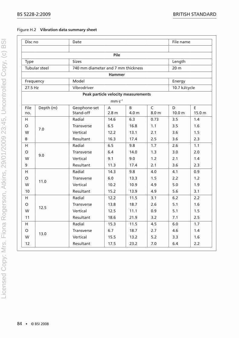
BS 5228-2:2009
84 • © BSI 2008
BritiSh Standard
Figure h.2 Vibration data summary sheet
disc no date File name
Pile
type Sizes Length
tubular steel 740 mm diameter and 7 mm thickness 20 m
Hammer
Frequency Model Energy
27.5 hz Vibrodriver 10.7 kJ/cycle
Peak particle velocity measurements
mm·s–1
File no.
depth (m) Geophone-set Stand-off
a 2.8 m
B 4.0 m
C 8.0 m
d 10.0 m
E 15.0 m
h
7.0
radial 14.6 6.3 0.73 3.5 1.4
O transverse 6.5 16.8 1.1 3.5 1.6
W Vertical 12.2 13.1 2.1 3.6 1.5
8 resultant 16.3 17.4 2.5 3.6 2.3
h
9.0
radial 6.5 9.8 1.7 2.6 1.1
O transverse 6.4 14.0 1.3 3.0 2.0
W Vertical 9.1 9.0 1.2 2.1 1.4
9 resultant 11.3 17.4 2.1 3.6 2.3
h
11.0
radial 14.3 9.8 4.0 4.1 0.9
O transverse 6.0 13.3 1.5 2.2 1.2
W Vertical 10.2 10.9 4.9 5.0 1.9
10 resultant 15.2 13.9 4.9 5.6 3.1
h
12.5
radial 12.2 11.5 3.1 6.2 2.2
O transverse 13.8 18.7 2.6 5.1 1.6
W Vertical 12.5 11.1 0.9 5.1 1.5
11 resultant 18.6 21.9 3.2 7.1 2.5
h
13.0
radial 15.3 11.5 4.5 6.0 1.7
O transverse 6.7 18.7 2.7 4.6 1.4
W Vertical 15.5 13.2 5.2 3.3 1.6
12 resultant 17.5 23.2 7.0 6.4 2.2
Lice
nsed
Cop
y: M
rs. F
iona
Rog
erso
n, A
tkin
s, 2
9/01
/200
9 23
:45,
Unc
ontr
olle
d C
opy,
(c)
BS
I

BritiSh Standard
© BSI 2008 • 85
BS 5228-2:2009
Bibliography
Standards publications
For dated references, only the edition cited applies. For undated references, the latest edition of the referenced document (including any amendments) applies.
BS 5228-1:2008, Code of practice for noise and vibration control on construction and open sites – Part 1: Noise
BS 5228-4:1992 (withdrawn), Noise and vibration control on construction and open sites – Part 4: Code of practice for noise and vibration control applicable to piling operations
BS 6187, Code of practice for demolition
BS 6472 (both parts), Guide to evaluation of human exposure to vibration in buildings
BS 7385-1:1990, Evaluation and measurement for vibration in buildings – Part 1: Guide for measurement of vibrations and evaluation of their effects on buildings
BS 7385-2, Evaluation and measurement for vibration in buildings – Part 2: Guide to damage levels from groundborne vibration
BS 6841, Guide to measurement and evaluation of human exposure to whole‑body mechanical vibration and repeated shock
iSO/FdiS 10137, Bases for design of structures – Serviceability of buildings and walkways against vibrations
EtS 300 019 (all parts), Equipment engineering (EE) – Environmental conditions and environmental tests for telecommunications equipment
Other publications
GrEat Britain dEPartMEnt OF thE EnVirOnMEnt, [1] tranSPOrt and thE rEGiOnS. The environmental effects of production blasting from surface mineral workings. London: the Stationery Office, 1998.
GrEat Britain. Control of Vibration at Work regulations 2005. [2] London: the Stationery Office.
hEaLth and SaFEtY EXECUtiVE. [3] Hand‑arm vibration – The Control of Vibration at Work Regulations 2005 – Guidance on Regulations. L140. Sudbury: hSE Books, 2005.
hEaLth and SaFEtY EXECUtiVE. [4] Whole‑body vibration – The Control of Vibration at Work Regulations 2005 – Guidance on Regulations. L141. Sudbury: hSE Books, 2005.
GrEat Britain. Construction (design and Management) [5] regulations 2007. London: the Stationery Office.
GrEat Britain. Construction (design and Management) [6] regulations 1994. London: hMSO.
GrEat Britain. Construction (health, Safety and Welfare) [7] regulations 1996. London: hMSO.Li
cens
ed C
opy:
Mrs
. Fio
na R
oger
son,
Atk
ins,
29/
01/2
009
23:4
5, U
ncon
trol
led
Cop
y, (
c) B
SI

BS 5228-2:2009
86 • © BSI 2008
BritiSh Standard
hEaLth and SaFEtY EXECUtiVE. [8] Managing health and safety in construction – Construction (Design and Management) Regulations 2007 (CDM) – Approved Code of Practice. L144. Sudbury: hSE Books, 2007.
GrEat Britain. Control of Pollution act 1974. London: hMSO.[9]
GrEat Britain. Environmental Protection act 1990. London: [10] hMSO.
hiLLEr d. M. and CraBB G. i. [11] Groundborne vibration caused by mechanised construction works. trL report 429. Wokingham: trL, 2000.
OFFiCE OF thE dEPUtY PriME MiniStEr. [12] Minerals Planning Guidance 9 – Planning and Compensation Act 1991 – Interim development order permissions (IDOS): conditions. MPG 9. norwich: the Stationery Office, 1992.
OFFiCE OF thE dEPUtY PriME MiniStEr. [13] Minerals policy statement 2 – Controlling and mitigating the environmental effects of mineral extraction in England. MPS 2. London: OdPM, 2005.
hanSOn, Carl E., tOWErS, david a. and MEiStEr, Lance d. [14] Transit noise and vibration impact assessment. Fta-Va-90-1003-06. Washington: US department of transportation, Federal transit administration, Office of Planning and Environment, 2006.
GrEat Britain. Pollution Control and Local Government [15] (northern ireland) Order 1978. Belfast: hMSO.
GrEat Britain. health and Safety at Work etc. act 1974. [16] London: hMSO
GrEat Britain. health and Safety at Work (northern ireland) [17] Order 1978. Belfast: hMSO.
EUrOPEan COMMUnitiES. directive 2002/44/EC of 6 July 2002 on [18] the minimum health and safety requirements regarding the risks arising from physical agents (vibration). Luxembourg: Office for Official Publications of the European Communities, 2002.
GrEat Britain. Control of noise (appeals) regulations 1975. [19] London: hMSO.
GrEat Britain. Statutory nuisance (appeals) regulations 1990. [20] London: hMSO.
GrEat Britain. Control of noise (appeals) regulations (northern [21] ireland) 1978. Belfast: hMSO.
GrEat Britain. Control of noise (appeals) (Scotland) [22] regulations 1983. London: hMSO.
GrEat Britain. Building regulations 2000 and subsequent [23] amendments. London: the Stationery Office.
GrEat Britain. Building Standards (Scotland) regulations 1990 [24] and subsequent amendments. London: hMSO.
GrEat Britain. Building regulations (northern ireland) 2000. [25] London: the Stationery Office.
GrEat Britain. Building (Scotland) act 2003. London: the [26] Stationery Office.
Lice
nsed
Cop
y: M
rs. F
iona
Rog
erso
n, A
tkin
s, 2
9/01
/200
9 23
:45,
Unc
ontr
olle
d C
opy,
(c)
BS
I

BritiSh Standard
© BSI 2008 • 87
BS 5228-2:2009
GrEat Britain. noise insulation regulations 1975. London: [27] hMSO.
GrEat Britain. noise insulation (Scotland) regulations 1975. [28] London: hMSO.
GrEat Britain. noise insulation (northern ireland) [29] regulations 1995. Belfast: hMSO.
GrEat Britain. Land Compensation act 1973. London: hMSO.[30]
GrEat Britain. Land Compensation (Scotland) act 1973. London: [31] hMSO.
GrEat Britain. Land acquisition and Compensation (northern [32] ireland) Order 1973. Belfast: hMSO.
GrEat Britain. highways act 1980. London: hMSO.[33]
GrEat Britain. noise insulation (railways and Other Guided [34] transport Systems) regulations 1995. London: hMSO.
OFFiCE OF thE dEPUtY PriME MiniStEr. [35] Minerals Planning Guidance 3 – Coal mining and colliery spoil. MPG 3. norwich: the Stationery Office, 1999.
GrEat Britain dEPartMEnt FOr COMMUnitiES and LOCaL [36] GOVErnMEnt. Minerals policy statement 1 – Planning and minerals. MPS 1. London: dCLG, 2006.
GrEat Britain. Coal industry act 1994. London: hMSO.[37]
GrEat Britain. Coal industry nationalisation act 1946. London: [38] hMSO.
GrEat Britain. Opencast Coal act 1958. London: hMSO.[39]
GrEat Britain. town and Country Planning act 1990. London: [40] hMSO.
GrEat Britain. Planning and Compulsory Purchase act 2004. [41] London: hMSO.
GrEat Britain. town and Country Planning (General [42] development Procedure) Order 1995. London: hMSO.
GrEat Britain. town and Country Planning (Environmental [43] impact assessment) (England and Wales) regulations 1999. London: the Stationery Office.
GrEat Britain. town and Country Planning (Scotland) act 1972. [44] London: hMSO.
GrEat Britain. Planning and Compensation act 1991. London: [45] hMSO.
GrEat Britain. Planning (northern ireland) Order 1991. London: [46] hMSO.
GrEat Britain. Environment act 1995. London: hMSO.[47]
dEPartMEnt FOr COMMUnitiES and LOCaL GOVErnMEnt. [48] Planning and minerals – Practice guide. 06SCdd04156. Wetherby: dCLG Publications, 2006.
SCOttiSh OFFiCE dEVELOPMEnt dEPartMEnt. [49] National Planning Policy Guideline 4 – Land for mineral working. nPPG 4. Crown Copyright, 1994.
Lice
nsed
Cop
y: M
rs. F
iona
Rog
erso
n, A
tkin
s, 2
9/01
/200
9 23
:45,
Unc
ontr
olle
d C
opy,
(c)
BS
I

BS 5228-2:2009
88 • © BSI 2008
BritiSh Standard
SCOttiSh OFFiCE dEVELOPMEnt dEPartMEnt. [50] Planning Advice Note 50 – Controlling the environmental effects of surface mineral workings. Pan 50. Crown Copyright, 1996.
OFFiCE OF thE dEPUtY PriME MiniStEr. [51] Minerals Planning Guidance 2 – Applications, permissions and conditions. MPG 2. norwich: the Stationery Office, 1998.
OFFiCE OF thE dEPUtY PriME MiniStEr. [52] Minerals Planning Guidance 8 – Planning and Compensation Act 1991 – Interim development order permissions (IDOS): statutory procedures and procedures. MPG 8. norwich: the Stationery Office, 1991.
StEFFEnS, r.J., [53] Structural vibration and damage. BrE report 69. Watford: BrE Press, 1974.
hEad, J.M. and JardinE, F.M. [54] Ground‑borne vibrations arising from piling. Ciria technical note 142. London: Ciria, 1992.
BUiLdinG rESEarCh EStaBLiShMEnt. [55] Damage to structures from ground‑borne vibration. dG 403. Watford: BrE Press, 1995.
UnGar E.E., StUrZ d.h. and aMiCK C.h. Vibration control design [56] of high technology facilities. Sound and vibration, July 1990.
WhitE, d., FinLaY, t., BOLtOn, M. and BEarSS, G. [57] Press‑in piling: Ground vibration and noise during pile installation. Proceeding of the international deep Foundations Congress. Orlando, USa. aSCE Special Publication 116, PP 363–371. 2002.
SCOtLand. [58] Planning and Compensation Act 1991 – Interim Development Order – Permissions, operating, restoration and after care conditions in Scotland. Circular 26/1992. Edinburgh: the Scottish Government, 1992.
GrEat Britain. Quarries (Explosives) regulations 1988. London: [59] hMSO.
GrEat Britain. Quarries (Explosives) regulations (northern [60] ireland) 2006. London: the Stationery Office.
SiSKind, d.E., StaChUra, V.J., StaGG, M.S., and KOPP, J. W., [61] Structure response and damage produced by airblast from surface mining. ri 8485. Washington d.C.: US Bureau of Mines report of investigations, 1980.
Further readingNOTE These publications were listed in the previous edition of BS 5228. They are no longer specifically referred to in the standard but have been retained as they provide additional guidance.
CrOCKEtt, J.h.a. Piling vibrations and structural fatigue. Proceedings of 1979 ICE Conference on recent developments in the design and construction of piles, PP.305–320. London: thomas telford, 1980.
dOWdinG, C.h. Blast vibration monitoring and control. Englewood Cliffs, new Jersey, USa: Prentice-hall, inc., 1985.
hEaLth and SaFEtY EXECUtiVE. Control of Noise in Quarries. hSG 109. Sudbury: hSE Books, 1993. iSBn 07176 0648 1.
inStitUtiOn OF CiViL EnGinEErS. Specification for piling and embedded retaining walls. Second edition. London: thomas telford Ltd, 2007. iSBn 9780727733580.
Lice
nsed
Cop
y: M
rs. F
iona
Rog
erso
n, A
tkin
s, 2
9/01
/200
9 23
:45,
Unc
ontr
olle
d C
opy,
(c)
BS
I

BritiSh Standard
© BSI 2008 • 89
BS 5228-2:2009
WaLLEr, r.a. (roy Waller associates). Environmental effects of surface mineral workings. department of the Environment research report, London: the Stationery Office, 1994.
WiSS, J.F. Vibrations during construction operations. Proceedings of the American Society of Civil Engineers, Journal of the Construction Division. 100 (CO3), September 1974, PP.239–246.
W.S.atKinS EnGinEErinG SErViCES (for the department of the Environment). The control of noise at surface mineral workings, London, the Stationery Office, 1990. iSBn 0 11 752 338 0.
WYnnE, C.P. A review of bearing pile types. Ciria report PG. 1, January 1977: reprinted 1988. available from Ciria, Classic house, 174–180 Old Street, London, EC1V 9BP.
Lice
nsed
Cop
y: M
rs. F
iona
Rog
erso
n, A
tkin
s, 2
9/01
/200
9 23
:45,
Unc
ontr
olle
d C
opy,
(c)
BS
I

BS 5228-2:2009 BritiSh Standard
This page deliberately left blank
Lice
nsed
Cop
y: M
rs. F
iona
Rog
erso
n, A
tkin
s, 2
9/01
/200
9 23
:45,
Unc
ontr
olle
d C
opy,
(c)
BS
I

This page deliberately left blank
Lice
nsed
Cop
y: M
rs. F
iona
Rog
erso
n, A
tkin
s, 2
9/01
/200
9 23
:45,
Unc
ontr
olle
d C
opy,
(c)
BS
I

BSI is the independent national body responsible for preparing British Standards. It presents the UK view on standards in Europe and at the international level.
It is incorporated by Royal Charter.
British Standards Institution (BSI)
raising standards worldwide™
BSI Group Headquarters
389 Chiswick High Road London W4 4AL UK
Tel +44 (0)20 8996 9001Fax +44 (0)20 8996 7001www.bsigroup.com/standards
RevisionsBritish Standards are updated by amendment or revision. Users of BritishStandards should make sure that they possess the latest amendments oreditions.
It is the constant aim of BSI to improve the quality of our products andservices. We would be grateful if anyone finding an inaccuracy orambiguity while using this British Standard would inform the Secretary ofthe technical committee responsible, the identity of which can be foundon the inside front cover.
Tel: +44 (0)20 8996 9000 Fax: +44 (0)20 8996 7400BSI offers members an individual updating service called PLUS whichensures that subscribers automatically receive the latest editions ofstandards.
Buying standardsOrders for all BSI, international and foreign standards publicationsshould be addressed to BSI Customer Services.
Tel: +44 (0)20 8996 9001 Fax: +44 (0)20 8996 7001Email: [email protected] may also buy directly using a debit/credit card from the BSI Shopon the website www.bsigroup.com/shopIn response to orders for international standards, it is BSI policy tosupply the BSI implementation of those that have been publishedas British Standards, unless otherwise requested.
Information on standardsBSI provides a wide range of information on national, European andinternational standards through its Library.
Various BSI electronic information services are also available which givedetails on all its products and services. Contact the Information Centre.
Tel: +44 (0)20 8996 7111 Fax: +44 (0)20 8996 7048 Email: [email protected] members of BSI are kept up to date with standardsdevelopments and receive substantial discounts on the purchase priceof standards. For details of these and other benefits contact MembershipAdministration.
Tel: +44 (0)20 8996 7002 Fax: +44 (0)20 8996 7001 Email: [email protected] Information regarding online access to British Standards via BritishStandards Online can be found at www.bsigroup.com/BSOLFurther information about BSI is available on the BSI website atwww.bsigroup.com
CopyrightCopyright subsists in all BSI publications. BSI also holds the copyright, in the UK, of thepublications of the international standardization bodies. Except as permitted under theCopyright, Designs and Patents Act 1988 no extract may be reproduced, stored in a retrievalsystem or transmitted in any form or by any means – electronic, photocopying, recording orotherwise – without prior written permission from BSI. This does not preclude the free use, in the course of implementing the standard of necessarydetails such as symbols, and size, type or grade designations. If these details are to be used forany other purpose than implementation then the prior written permission of BSI must beobtained. Details and advice can be obtained from the Copyright & Licensing Manager.
Tel: +44 (0)20 8996 7070 Email: [email protected]
WB9423_BSI_StandardColCov_noK_AW:BSI FRONT COVERS 5/9/08 12:55 Page 2
Lice
nsed
Cop
y: M
rs. F
iona
Rog
erso
n, A
tkin
s, 2
9/01
/200
9 23
:45,
Unc
ontr
olle
d C
opy,
(c)
BS
I