bsh - servo motor - motor manual
TRANSCRIPT

BSH
0198441113837 01/2017
0198
4411
1383
7.04
www.schneider-electric.com
BSHServo MotorMotor Manual01/2017

The information provided in this documentation contains general descriptions and/or technical character-istics of the performance of the products contained herein. This documentation is not intended as a substitute for and is not to be used for determining suitability or reliability of these products for specific user applications. It is the duty of any such user or integrator to perform the appropriate and complete risk analysis, evaluation and testing of the products with respect to the relevant specific application or use thereof. Neither Schneider Electric nor any of its affiliates or subsidiaries shall be responsible or liable for misuse of the information contained herein. If you have any suggestions for improvements or amendments or have found errors in this publication, please notify us. No part of this document may be reproduced in any form or by any means, electronic or mechanical, including photocopying, without express written permission of Schneider Electric.All pertinent state, regional, and local safety regulations must be observed when installing and using this product. For reasons of safety and to help ensure compliance with documented system data, only the manufacturer should perform repairs to components.When devices are used for applications with technical safety requirements, the relevant instructions must be followed. Failure to use Schneider Electric software or approved software with our hardware products may result in injury, harm, or improper operating results.Failure to observe this information can result in injury or equipment damage.© 2017 Schneider Electric. All Rights Reserved.
2 0198441113837 01/2017

Table of Contents
Safety Information. . . . . . . . . . . . . . . . . . . . . . . . . . . . . . . . . . . . . . . . . . . . 5About the Book . . . . . . . . . . . . . . . . . . . . . . . . . . . . . . . . . . . . . . . . . . . . . . 7
Chapter 1 Introduction . . . . . . . . . . . . . . . . . . . . . . . . . . . . . . . . . . . . . . . . . . . . . . . . . 11Motor Family . . . . . . . . . . . . . . . . . . . . . . . . . . . . . . . . . . . . . . . . . . . . . . . . . . . . . . . . . . . . . 12Options and Accessories. . . . . . . . . . . . . . . . . . . . . . . . . . . . . . . . . . . . . . . . . . . . . . . . . . . . 12Nameplate . . . . . . . . . . . . . . . . . . . . . . . . . . . . . . . . . . . . . . . . . . . . . . . . . . . . . . . . . . . . . . . 13Type Code . . . . . . . . . . . . . . . . . . . . . . . . . . . . . . . . . . . . . . . . . . . . . . . . . . . . . . . . . . . . . . . 15
Chapter 2 Technical Data . . . . . . . . . . . . . . . . . . . . . . . . . . . . . . . . . . . . . . . . . . . . . . 17General Characteristics . . . . . . . . . . . . . . . . . . . . . . . . . . . . . . . . . . . . . . . . . . . . . . . . . . . . . 18Environmental Conditions . . . . . . . . . . . . . . . . . . . . . . . . . . . . . . . . . . . . . . . . . . . . . . . . . . . 20Approved Drives . . . . . . . . . . . . . . . . . . . . . . . . . . . . . . . . . . . . . . . . . . . . . . . . . . . . . . . . . . 22Dimensions . . . . . . . . . . . . . . . . . . . . . . . . . . . . . . . . . . . . . . . . . . . . . . . . . . . . . . . . . . . . . . 23Shaft-Specific Data . . . . . . . . . . . . . . . . . . . . . . . . . . . . . . . . . . . . . . . . . . . . . . . . . . . . . . . . 34Motor-Specific Data . . . . . . . . . . . . . . . . . . . . . . . . . . . . . . . . . . . . . . . . . . . . . . . . . . . . . . . . 37Encoder . . . . . . . . . . . . . . . . . . . . . . . . . . . . . . . . . . . . . . . . . . . . . . . . . . . . . . . . . . . . . . . . . 49Holding Brake . . . . . . . . . . . . . . . . . . . . . . . . . . . . . . . . . . . . . . . . . . . . . . . . . . . . . . . . . . . . 51Certifications . . . . . . . . . . . . . . . . . . . . . . . . . . . . . . . . . . . . . . . . . . . . . . . . . . . . . . . . . . . . . 52Conditions for UL 1004-1, UL 1004-6 and CSA 22.2 No. 100. . . . . . . . . . . . . . . . . . . . . . . . 52
Chapter 3 Installation . . . . . . . . . . . . . . . . . . . . . . . . . . . . . . . . . . . . . . . . . . . . . . . . . 533.1 Electromagnetic Compatibility (EMC) . . . . . . . . . . . . . . . . . . . . . . . . . . . . . . . . . . . . . . . . . . 55
Electromagnetic Compatibility (EMC) . . . . . . . . . . . . . . . . . . . . . . . . . . . . . . . . . . . . . . . . . . 553.2 Mechanical Installation . . . . . . . . . . . . . . . . . . . . . . . . . . . . . . . . . . . . . . . . . . . . . . . . . . . . . 57
Before Mounting . . . . . . . . . . . . . . . . . . . . . . . . . . . . . . . . . . . . . . . . . . . . . . . . . . . . . . . . . . 58Cable Specifications . . . . . . . . . . . . . . . . . . . . . . . . . . . . . . . . . . . . . . . . . . . . . . . . . . . . . . . 60Mounting The Motor . . . . . . . . . . . . . . . . . . . . . . . . . . . . . . . . . . . . . . . . . . . . . . . . . . . . . . . 63Installation and Connection of IP67 Kit (Accessory) . . . . . . . . . . . . . . . . . . . . . . . . . . . . . . . 65
3.3 Electrical Installation . . . . . . . . . . . . . . . . . . . . . . . . . . . . . . . . . . . . . . . . . . . . . . . . . . . . . . . 66Connectors and Connector Assignments . . . . . . . . . . . . . . . . . . . . . . . . . . . . . . . . . . . . . . . 67Power and Encoder Connection . . . . . . . . . . . . . . . . . . . . . . . . . . . . . . . . . . . . . . . . . . . . . . 71Holding Brake Connection. . . . . . . . . . . . . . . . . . . . . . . . . . . . . . . . . . . . . . . . . . . . . . . . . . . 77
Chapter 4 Commissioning . . . . . . . . . . . . . . . . . . . . . . . . . . . . . . . . . . . . . . . . . . . . . . 79Commissioning . . . . . . . . . . . . . . . . . . . . . . . . . . . . . . . . . . . . . . . . . . . . . . . . . . . . . . . . . . . 79
Chapter 5 Diagnostics and Troubleshooting . . . . . . . . . . . . . . . . . . . . . . . . . . . . . . . . 81Mechanical Issues . . . . . . . . . . . . . . . . . . . . . . . . . . . . . . . . . . . . . . . . . . . . . . . . . . . . . . . . . 82Electrical Issues. . . . . . . . . . . . . . . . . . . . . . . . . . . . . . . . . . . . . . . . . . . . . . . . . . . . . . . . . . . 82
Chapter 6 Accessories and Spare Parts . . . . . . . . . . . . . . . . . . . . . . . . . . . . . . . . . . . 83IP67 Kit . . . . . . . . . . . . . . . . . . . . . . . . . . . . . . . . . . . . . . . . . . . . . . . . . . . . . . . . . . . . . . . . . 84Connectors . . . . . . . . . . . . . . . . . . . . . . . . . . . . . . . . . . . . . . . . . . . . . . . . . . . . . . . . . . . . . . 85Motor Cables . . . . . . . . . . . . . . . . . . . . . . . . . . . . . . . . . . . . . . . . . . . . . . . . . . . . . . . . . . . . . 86Encoder Cables . . . . . . . . . . . . . . . . . . . . . . . . . . . . . . . . . . . . . . . . . . . . . . . . . . . . . . . . . . . 89
Chapter 7 Service, Maintenance, and Disposal . . . . . . . . . . . . . . . . . . . . . . . . . . . . . 91Service Addresses. . . . . . . . . . . . . . . . . . . . . . . . . . . . . . . . . . . . . . . . . . . . . . . . . . . . . . . . . 92Maintenance . . . . . . . . . . . . . . . . . . . . . . . . . . . . . . . . . . . . . . . . . . . . . . . . . . . . . . . . . . . . . 92Replacing the Motor . . . . . . . . . . . . . . . . . . . . . . . . . . . . . . . . . . . . . . . . . . . . . . . . . . . . . . . 94Shipping, Storage, Disposal . . . . . . . . . . . . . . . . . . . . . . . . . . . . . . . . . . . . . . . . . . . . . . . . . 95
Glossary . . . . . . . . . . . . . . . . . . . . . . . . . . . . . . . . . . . . . . . . . . . . . . . . . . . . . 97Index . . . . . . . . . . . . . . . . . . . . . . . . . . . . . . . . . . . . . . . . . . . . . . . . . . . . . 99
0198441113837 01/2017 3

4 0198441113837 01/2017

Safety Information
Important Information
NOTICERead these instructions carefully, and look at the equipment to become familiar with the device before trying to install, operate, service, or maintain it. The following special messages may appear throughout this documentation or on the equipment to warn of potential hazards or to call attention to information that clarifies or simplifies a procedure.
PLEASE NOTEElectrical equipment should be installed, operated, serviced, and maintained only by qualified personnel. No responsibility is assumed by Schneider Electric for any consequences arising out of the use of this material.A qualified person is one who has skills and knowledge related to the construction and operation of electrical equipment and its installation, and has received safety training to recognize and avoid the hazards involved.
0198441113837 01/2017 5

6 0198441113837 01/2017

About the Book
At a Glance
Document ScopeThis manual describes technical characteristics, installation, commissioning, and maintenance of the servo motors BSH.
Validity NoteThis manual is valid for the standard products listed in the chapter Type Code.For product compliance and environmental information (RoHS, REACH, PEP, EOLI, etc.), go to www.schneider-electric.com/green-premium.The technical characteristics of the devices described in this document also appear online. To access this information online:
The characteristics that are presented in this manual should be the same as those characteristics that appear online. In line with our policy of constant improvement, we may revise content over time to improve clarity and accuracy. If you see a difference between the manual and online information, use the online information as your reference.
Product Related InformationThe use and application of the information contained herein require expertise in the design and programming of automated control systems.Only you, the user, machine builder or integrator, can be aware of all the conditions and factors present during installation and setup, operation, repair and maintenance of the machine or process.You must also consider any applicable standards and/or regulations with respect to grounding of all equipment. Verify compliance with any safety information, different electrical requirements, and normative standards that apply to your machine or process in the use of this equipment.Many components of the equipment, including the printed circuit board, operate with mains voltage, or present transformed high currents, and/or high voltages.The motor itself generates voltage when the motor shaft is rotated.
Step Action1 Go to the Schneider Electric home page www.schneider-electric.com.2 In the Search box type the reference of a product or the name of a product range.
Do not include blank spaces in the reference or product range. To get information on grouping similar modules, use asterisks (*).
3 If you entered a reference, go to the Product Datasheets search results and click on the reference that interests you.If you entered the name of a product range, go to the Product Ranges search results and click on the product range that interests you.
4 If more than one reference appears in the Products search results, click on the reference that interests you.
5 Depending on the size of your screen, you may need to scroll down to see the data sheet.6 To save or print a data sheet as a .pdf file, click Download XXX product datasheet.
0198441113837 01/2017 7

This equipment has been designed to operate outside of any hazardous location. Only install this equipment in zones known to be free of a hazardous atmosphere.
If the power stage is disabled unintentionally, for example as a result of a power outage, errors or functions, the motor is no longer decelerated in a controlled way. Overload, errors or incorrect use may cause the holding brake to no longer operate properly and may result in premature wear.
DANGERELECTRIC SHOCK, EXPLOSION, OR ARC FLASH Disconnect all power from all equipment including connected devices prior to removing any covers or
doors, or installing or removing any accessories, hardware, cables, or wires. Place a "Do Not Turn On" or equivalent hazard label on all power switches and lock them in the non-
energized position. Wait 15 minutes to allow the residual energy of the DC bus capacitors to discharge. Measure the voltage on the DC bus with a properly rated voltage sensing device and verify that the
voltage is less than 42.4 Vdc. Do not assume that the DC bus is voltage-free when the DC bus LED is off. Block the motor shaft to prevent rotation prior to performing any type of work on the drive system. Do not create a short-circuit across the DC bus terminals or the DC bus capacitors. Replace and secure all covers, accessories, hardware, cables, and wires and confirm that a proper
ground connection exists before applying power to the unit. Use only the specified voltage when operating this equipment and any associated products.Failure to follow these instructions will result in death or serious injury.
DANGERPOTENTIAL FOR EXPLOSIONInstall and use this equipment in non-hazardous locations only.Failure to follow these instructions will result in death or serious injury.
WARNINGUNINTENDED EQUIPMENT OPERATION Verify that movements without braking effect cannot cause injuries or equipment damage. Verify the function of the holding brake at regular intervals. Do not use the holding brake as a service brake. Do not use the holding brake for safety-related purposes.Failure to follow these instructions can result in death, serious injury, or equipment damage.
8 0198441113837 01/2017

1 For additional information, refer to NEMA ICS 1.1 (latest edition), "Safety Guidelines for the Application, Installation, and Maintenance of Solid State Control" and to NEMA ICS 7.1 (latest edition), "Safety Standards for Construction and Guide for Selection, Installation and Operation of Adjustable-Speed Drive Systems" or their equivalent governing your particular location.
Terminology Derived from StandardsThe technical terms, terminology, symbols and the corresponding descriptions in this manual, or that appear in or on the products themselves, are generally derived from the terms or definitions of international standards.In the area of functional safety systems, drives and general automation, this may include, but is not limited to, terms such as safety, safety function, safe state, fault, fault reset, malfunction, failure, error, error message, dangerous, etc.Among others, these standards include:
WARNINGLOSS OF CONTROL The designer of any control scheme must consider the potential failure modes of control paths and,
for certain critical control functions, provide a means to achieve a safe state during and after a path failure. Examples of critical control functions are emergency stop and overtravel stop, power outage and restart.
Separate or redundant control paths must be provided for critical control functions. System control paths may include communication links. Consideration must be given to the
implications of unanticipated transmission delays or failures of the link. Observe all accident prevention regulations and local safety guidelines.1 Each implementation of this equipment must be individually and thoroughly tested for proper operation
before being placed into service.Failure to follow these instructions can result in death, serious injury, or equipment damage.
Standard DescriptionEN 61131-2:2007 Programmable controllers, part 2: Equipment requirements and tests.ISO 13849-1:2008 Safety of machinery: Safety related parts of control systems.
General principles for design.EN 61496-1:2013 Safety of machinery: Electro-sensitive protective equipment.
Part 1: General requirements and tests.ISO 12100:2010 Safety of machinery - General principles for design - Risk assessment and risk
reductionEN 60204-1:2006 Safety of machinery - Electrical equipment of machines - Part 1: General
requirementsEN 1088:2008ISO 14119:2013
Safety of machinery - Interlocking devices associated with guards - Principles for design and selection
ISO 13850:2006 Safety of machinery - Emergency stop - Principles for designEN/IEC 62061:2005 Safety of machinery - Functional safety of safety-related electrical, electronic,
and electronic programmable control systemsIEC 61508-1:2010 Functional safety of electrical/electronic/programmable electronic safety-
related systems: General requirements.IEC 61508-2:2010 Functional safety of electrical/electronic/programmable electronic safety-
related systems: Requirements for electrical/electronic/programmable electronic safety-related systems.
IEC 61508-3:2010 Functional safety of electrical/electronic/programmable electronic safety-related systems: Software requirements.
IEC 61784-3:2008 Digital data communication for measurement and control: Functional safety field buses.
2006/42/EC Machinery Directive2014/30/EU Electromagnetic Compatibility Directive2014/35/EU Low Voltage Directive
0198441113837 01/2017 9

In addition, terms used in the present document may tangentially be used as they are derived from other standards such as:
Finally, the term zone of operation may be used in conjunction with the description of specific hazards, and is defined as it is for a hazard zone or danger zone in the Machinery Directive (2006/42/EC) and ISO 12100:2010.NOTE: The aforementioned standards may or may not apply to the specific products cited in the present documentation. For more information concerning the individual standards applicable to the products described herein, see the characteristics tables for those product references.
Standard DescriptionIEC 60034 series Rotating electrical machinesIEC 61800 series Adjustable speed electrical power drive systemsIEC 61158 series Digital data communications for measurement and control – Fieldbus for use in
industrial control systems
10 0198441113837 01/2017

BSHIntroduction0198441113837 01/2017
Introduction
Chapter 1Introduction
What Is in This Chapter?This chapter contains the following topics:
Topic PageMotor Family 12Options and Accessories 12Nameplate 13Type Code 15
0198441113837 01/2017 11

Introduction
Motor Family
The series BSH motors are low-inertia AC synchronous servo motors designed for highly dynamic positioning tasks.A drive system consists of the servo motor and the appropriate drive (see page 22). Maximum performance requires the motor and drive to be adapted to each other.
CharacteristicsThe motors have the following features: Overload protection by integrated temperature sensor (external evaluation required) Low moment of inertia High power density Excellent dynamics High overload capability Broad torque range Special winding for low phase currents Motor connections via circular connectors or terminal box Easy commissioning via electronic nameplate in SinCos encoder Low maintenance
Options and Accessories
OptionsThe motors are available with various options such as: Various encoder systems Holding brake Various shaft versions Various degrees of protection Various lengths Various sizes Various winding versions Various connection versions
AccessoriesRefer to the chapter Accessories and Spare Parts (see page 83).Gearboxes adapted to the motor can be found in the Lexium 32 motion control catalog.
12 0198441113837 01/2017
Introduction
Nameplate
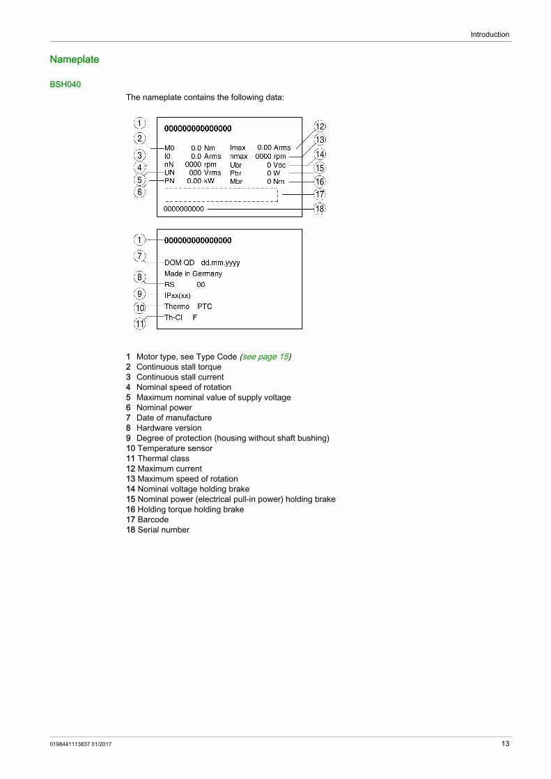
BSH040The nameplate contains the following data:
1 Motor type, see Type Code (see page 15)2 Continuous stall torque3 Continuous stall current4 Nominal speed of rotation5 Maximum nominal value of supply voltage6 Nominal power7 Date of manufacture8 Hardware version9 Degree of protection (housing without shaft bushing)10 Temperature sensor11 Thermal class12 Maximum current13 Maximum speed of rotation14 Nominal voltage holding brake15 Nominal power (electrical pull-in power) holding brake16 Holding torque holding brake17 Barcode18 Serial number
0198441113837 01/2017 13

Introduction
BSH055 ... BSH205The nameplate contains the following data:
1 Motor type, see Type Code (see page 15)2 Identification number3 Continuous stall torque4 Continuous stall current5 Nominal speed of rotation6 Maximum nominal value of supply voltage7 Nominal power8 Thermal class9 Barcode10 Maximum current11 Serial number12 Date of manufacture13 Maximum speed of rotation14 Hardware version15 Degree of protection (housing without shaft bushing)16 Temperature sensor17 Nominal voltage holding brake18 Nominal power (electrical pull-in power) holding brake19 Holding torque holding brake
14 0198441113837 01/2017

Introduction
Type Code
Type Code
If you have questions concerning the type code, contact your Schneider Electric sales office.
Designation Customized VersionIn the case of a customized version, position 8 of the type code is an "S". The subsequent number defines the customized version. Example: B••••••S1234Contact your machine vendor if you have questions concerning customized versions.
Item 1 2 3 4 5 6 7 8 9 10 11 12 13Type code (example) B S H 0 7 0 1 P 0 1 A 1 A
Item Meaning1 ... 3 Product family
BSH = Synchronous motor - low moment of inertia4 ... 6 Size (housing)
040 = 40 mm flange055 = 55 mm flange070 = 70 mm flange100 = 100 mm flange140 = 140 mm flange205 = 205 mm flange
7 Length1 = 1 stack2 = 2 stacks3 = 3 stacks4 = 4 stacks
8 WindingM = Optimized in terms of high torqueP = Optimized in terms of torque and speed of rotationT = Optimized in terms of high speed of rotationS = Customized version
9 Shaft and degree of protection1)
0 = Smooth shaft; degree of protection: shaft IP54, housing IP651 = Parallel key; degree of protection: shaft IP54, housing IP652 = Smooth shaft; degree of protection: shaft and housing IP653 = Parallel key; degree of protection: shaft and housing IP65
10 Encoder system1 = Absolute singleturn 128 Sin/Cos periods per revolution (SKS36)2 = Absolute multiturn 128 Sin/Cos periods per revolution (SKM36)6 = Absolute singleturn 16 Sin/Cos periods per revolution (SEK37)7 = Absolute multiturn 16 Sin/Cos periods per revolution (SEL37)
11 Holding brakeA = Without holding brakeF = With holding brake
12 Connection version1 = Straight connector2 = Angular connector 90°, can be rotated3 = Terminal box for power and holding brake, 90° angular connector for encoder, can be rotated
13 Mechanical interface - mountingA = International IEC Standard (at motor flange)P = International IEC standard (at motor flange), BSH1402T, BSH1403T and BSH1404P with power connector M40
1) In the case of mounting position IM V3 (drive shaft vertical, shaft end upward), the motor has a degree of protection of IP 50.
0198441113837 01/2017 15

Introduction
16 0198441113837 01/2017

BSHTechnical Data0198441113837 01/2017
Technical Data
Chapter 2Technical Data
What Is in This Chapter?This chapter contains the following topics:
Topic PageGeneral Characteristics 18Environmental Conditions 20Approved Drives 22Dimensions 23Shaft-Specific Data 34Motor-Specific Data 37Encoder 49Holding Brake 51Certifications 52Conditions for UL 1004-1, UL 1004-6 and CSA 22.2 No. 100 52
0198441113837 01/2017 17

Technical Data
General Characteristics
Service Life
The service life of the motors when operated correctly is limited primarily by the service life of the rolling bearing.The following operating conditions significantly reduce the service life: Installation altitude >1000 m (3281 ft) above mean sea level Rotary movements exclusively within a fixed angle of <100° Operation under vibration load >20 m/s2
Allowing sealing rings to run dry Contact of the seals with aggressive substances
Compressed Air ConnectionThe compressed air generates a permanent overpressure inside the motor. This overpressure inside the motor is used to obtain degree of protection IP67.Compressed air must also be available when the system is switched off, for example to maintain the required degree of protection during cleaning work. When the compressed air is switched off, the degree of protection is decreased to IP65. The degree of protection only relates to the motor itself, not to mounted components such as, for example, a gearbox.Special compressed air must be used:
Characteristic Value StandardMotor type AC synchronous servo motor -Thermal class F (155 °C) As per IEC 60034-1Vibration grade A As per IEC 60034-14Test voltage > 2400 Vac As per IEC 60034-1Perpendicularity normal class As per IEC 60072-1, DIN 42955Housing color Black RAL 9005 -Overvoltage category III As per IEC 61800-5-1
Protection class1) I As per IEC 61140, EN 50178
1) The signals of the holding brake at CN1 and the signals at CN2 meet the PELV requirements.
Bearing service life Unit Value
Nominal bearing service life L10h1) h 20000
1) Operating hours at a probability of failure of 10%
Characteristic Unit ValueNominal pressure bar
(psi)0.1 ... 0.3(1.45 ... 4.35)
Maximum air pressure bar(psi)
0.4(5.8)
Permissible humidity % 20 ... 30Other properties of the compressed air Free from dust, free from oil
18 0198441113837 01/2017

Technical Data
Tightening Torque and Property Class of Screws
Screw Unit ValueTightening torque of housing screws M3 Nm (lb•in) 1 (8.85)Tightening torque of housing screws M4 Nm (lb•in) 1.5 (13.28)Tightening torque of housing screws M5 Nm (lb•in) 5 (44.3)Tightening torque protective ground conductor M3 (BSH040)
Nm (lb•in) 0.9 (7.97)
Tightening torque protective ground conductor M4 (BSH055, BSH070, BSH100)
Nm (lb•in) 2.9 (25.7)
Tightening torque protective ground conductor M6 (BSH140, BSH205)
Nm (lb•in) 9.9 (87.3)
Property class of the screws - 8.8
0198441113837 01/2017 19

Technical Data
Environmental Conditions
Conditions for Operation
Conditions for Transportation and StorageThe environment during transportation and storage must be dry and free from dust.The storage time is primarily limited by the service life of the lubricants in the bearings. Do not store the product for more than 36 months and periodically operate the motor.If the holding brake is not used for an extended period of time, parts of the holding brake may corrode. Corrosion reduces the holding torque. See chapter Inspecting/Breaking In the Holding Brake (see page 93).
Vibration and ShockFor BSH040 ... BSH140
For BSH205
Characteristic Unit ValueClass as per IEC 60721-3-3 - 3K3, 3Z12, 3Z2, 3B2, 3C1, 3M6
Ambient temperature1) (no icing, non-condensing) °C(°F)
-20 ... 40(-4 ... 104)
Ambient temperature with current derating of 1% per °C (per 1.8 °F)1)
°C(°F)
40 ... 60(104 ... 140)
Relative humidity (non-condensing) % 5 ... 85
Installation altitude2) m(ft)
<1000(<3281)
Installation altitude with current reduction of 1% per 100 m (328 ft) at altitudes of more than 1000 m (3281 ft)2)3)
m(ft)
1000 ... 3000(3281 ... 9843)
1) Limit values with flanged motor (steel plate, height and width = 2.5 * motor flange, 10 mm (0.39 in) thickness, centered hole).
2) The installation altitude is defined in terms of altitude above mean sea level.3) For the correct functioning of the BSH040 motors, you must apply a separate surge protection device when
operating between 2000 and 3000 m.
Characteristic Unit ValueTemperature °C
(°F)-40 ... 70(-40 ... 158)
Relative humidity (non-condensing) % ≤75Set of class combinations as per IEC 60721-3-2 IE 21
Characteristic ValueVibration, sinusoidal Type test with 10 runs as per IEC 60068-2-6
0.15 mm (10 ... 60 Hz)20 m/s2 (60 ... 500 Hz)
Shock, semi-sinusoidal Type test with 3 shocks in each direction as per IEC 60068-2-27150 m/s2 (11 ms)
Characteristic ValueVibration, sinusoidal Type test with 10 runs as per IEC 60068-2-6
0.35 mm (10 ... 60 Hz)50 m/s2 (60 ... 150 Hz)
Continuous shock Type test with 3 shocks in each direction as per IEC 60068-2-29200 m/s2 (6 ms)
20 0198441113837 01/2017

Technical Data
Compatibility with Foreign SubstancesThe motor has been tested for compatibility with many known substances and with the latest available knowledge. Nonetheless, you must perform a compatibility test prior to using a foreign substance.
Degree of Protection
The motors can be equipped with an optional shaft sealing ring. With a shaft sealing ring, they have degree of protection IP65. The shaft sealing ring limits the maximum speed of rotation to 6000 rpm.Note the following: The shaft sealing ring is factory-pre-lubricated. If the seals run dry, this increases friction and greatly reduces the service life of the sealing rings.
Characteristic Unit ValueDegree of protection motor housing IP65 As per IEC 60034-5Degree of protection shaft bushing without shaft sealing ring IP541) As per IEC 60034-5
Degree of protection shaft bushing with shaft sealing ring IP651) As per IEC 60034-5
Degree of protection with IP67 kit IP671) As per IEC 60034-5
1) In the case of mounting position IM V3 (drive shaft vertical, shaft end up), the motor only has degree of protection IP50. The degree of protection only relates to the motor itself, not to mounted components such as, for example, a gearbox.
0198441113837 01/2017 21

Technical Data
Approved Drives
Drive systems may perform unintended movements if unapproved combinations of drive and motor are used. Even if motors are similar, different adjustment of the encoder system may be a source of hazards. Even if the connectors for motor connection and encoder connection match mechanically, this does not imply that the motor is approved for use.
The motor may be operated with the following drives:
When selecting, refer to the drive type and the level of mains voltage to select an appropriate drive product.In accordance with our continual introduction of new product, consult your local representative for additional compatible drive products as the become available.
WARNINGUNINTENDED MOVEMENTOnly use approved combinations of drive and motor.Failure to follow these instructions can result in death, serious injury, or equipment damage.
Drive BSH040 BSH055...BSH205LXM32 ✓ ✓LXM15 - ✓LXM05 - ✓✓ Approved- Not approved
22 0198441113837 01/2017

Technical Data
Dimensions
Dimensions BSH040
BSH... 0401 0402L Length without holding brake mm (in) 73.4 (2.89) 93.4 (3.68)L Length with holding brake mm (in) 99.4 (3.91) 119.4 (4.7)B Shaft length mm (in) 25 (0.98) 25 (0.98)C Shaft diameter mm (in) 8 (0.31) 8 (0.31)D Width of parallel key mm (in) 3 (0.12) 3 (0.12)E Shaft width with parallel key mm (in) 9.2 (0.36) 9.2 (0.36)F Length of parallel key mm (in) 12 (0.47) 12 (0.47)G Distance parallel key to shaft end mm (in) 4 (0.16) 4 (0.16)H Female thread of shaft DIN 332 DS M3 x 9 DIN 332 DS M3 x 9
Parallel key DIN 6885-A3x3x12 DIN 6885-A3x3x12
0198441113837 01/2017 23

Technical Data
Dimensions BSH055
BSH... 0551 0552 0553L Length without holding brake mm (in) 132.5 (5.22) 154.4 (6.08) 176.5 (6.95)L Length with holding brake mm (in) 159 (6.26) 181 (7.13) 203 (7.99)B Shaft length mm (in) 20 (0.79) 20 (0.79) 20 (0.79)C Shaft diameter mm (in) 9 (0.35) 9 (0.35) 9 (0.35)D Width of parallel key mm (in) 3 (0.12) 3 (0.12) 3 (0.12)E Shaft width with parallel key mm (in) 10.2 (0.4) 10.2 (0.4) 10.2 (0.4)F Length of parallel key mm (in) 12 (0.47) 12 (0.47) 12 (0.47)G Distance parallel key to shaft end mm (in) 4 (0.16) 4 (0.16) 4 (0.16)H Female thread of shaft DIN 332-D M3 DIN 332-D M3 DIN 332-D M3
Parallel key DIN 6885-A3x3x12 DIN 6885-A3x3x12 DIN 6885-A3x3x12
24 0198441113837 01/2017

Technical Data
Dimensions BSH070
BSH... 0701 0702 0703L Length without holding brake mm (in) 154 (6.06) 187 (7.36) 220 (8.66)L Length with holding brake mm (in) 180 (7.09) 213 (8.39) 254 (10)B Shaft length mm (in) 23 (0.91) 23 (0.91) 30 (1.18)C Shaft diameter mm (in) 11 (0.43) 11 (0.43) 14 (0.55)D Width of parallel key mm (in) 4 (0.16) 4 (0.16) 5 (0.2)E Shaft width with parallel key mm (in) 12.5 (0.49) 12.5 (0.49) 16 (0.63)F Length of parallel key mm (in) 18 (0.71) 18 (0.71) 20 (0.79)G Distance parallel key to shaft end mm (in) 2.5 (0.1) 2.5 (0.1) 5 (0.2)H Female thread of shaft DIN 332-D M4 DIN 332-D M4 DIN 332-D M5
Parallel key DIN 6885-A4x4x18 DIN 6885-A4x4x18 DIN 6885-A4x4x20
0198441113837 01/2017 25

Technical Data
Dimensions BSH100Hardware version ≥RS02:
BSH... 1001 1002 1003 1004L Length without
holding brakemm (in) 168.5 (6.63) 204.5 (8.05) 240.5 (9.47) 276.5 (10.89)
L Length with holding brake
mm (in) 199.5 (7.85) 235.5 (9.27) 271.5 (10.69) 307.5 (12.11)
B Shaft length mm (in) 40 (1.57) 40 (1.57) 40 (1.57) 50 (1.97)C Shaft diameter mm (in) 19 (0.75) 19 (0.75) 19 (0.75) 24 (0.94)D Width of parallel
keymm (in) 6 (0.24) 6 (0.24) 6 (0.24) 8 (0.31)
E Shaft width with parallel key
mm (in) 21.5 (0.85) 21.5 (0.85) 21.5 (0.85) 27 (1.06)
F Length of parallel key
mm (in) 30 (1.18) 30 (1.18) 30 (1.18) 40 (1.57)
G Distance parallel key to shaft end
mm (in) 5 (0.2) 5 (0.2) 5 (0.2) 5 (0.2)
H Female thread of shaft
DIN 332-D M6 DIN 332-D M6 DIN 332-D M6 DIN 332-D M8
J Connector distance without holding brake
mm (in) 34.5 (1.36) 34.5 (1.36) 34.5 (1.36) 34.5 (1.36)
J Connector distance with holding brake
mm (in) 29.8 (1.17) 29.8 (1.17) 29.8 (1.17) 29.8 (1.17)
Parallel key DIN 6885-A6x6x30 DIN 6885-A6x6x30 DIN 6885-A6x6x30 DIN 6885-A8x7x40
26 0198441113837 01/2017

Technical Data
Dimensions BSH100Hardware version <RS02:
BSH... 1001 1002 1003 1004L Length without
holding brakemm (in) 168.5 (6.63) 204.5 (8.05) 240.5 (9.47) 276.5 (10.89)
L Length with holding brake
mm (in) 199.5 (7.85) 235.5 (9.27) 271.5 (10.69) 307.5 (12.11)
B Shaft length mm (in) 40 (1.57) 40 (1.57) 40 (1.57) 50 (1.97)C Shaft diameter mm (in) 19 (0.75) 19 (0.75) 19 (0.75) 24 (0.94)D Width of parallel
keymm (in) 6 (0.24) 6 (0.24) 6 (0.24) 8 (0.31)
E Shaft width with parallel key
mm (in) 21.5 (0.85) 21.5 (0.85) 21.5 (0.85) 27 (1.06)
F Length of parallel key
mm (in) 30 (1.18) 30 (1.18) 30 (1.18) 40 (1.57)
G Distance parallel key to shaft end
mm (in) 5 (0.2) 5 (0.2) 5 (0.2) 5 (0.2)
H Female thread of shaft
DIN 332-D M6 DIN 332-D M6 DIN 332-D M6 DIN 332-D M8
Parallel key DIN 6885-A6x6x30 DIN 6885-A6x6x30 DIN 6885-A6x6x30 DIN 6885-A8x7x40
0198441113837 01/2017 27

Technical Data
Dimensions BSH140Hardware version ≥RS02:
BSH... 1401 1402M, 1402P 1403M, 1403P 1404ML Length without
holding brakemm (in) 217.5 (8.56) 272.5 (10.73) 327.5 (12.89) 382.5 (15.06)
L Length with holding brake
mm (in) 255.5 (10.06) 310.5 (12.22) 365.5 (14.39) 420.5 (16.56)
B Shaft length mm (in) 50 (1.97) 50 (1.97) 50 (1.97) 50 (1.97)C Shaft diameter mm (in) 24 (0.94) 24 (0.94) 24 (0.94) 24 (0.94)D Width of parallel
keymm (in) 8 (0.31) 8 (0.31) 8 (0.31) 8 (0.31)
E Shaft width with parallel key
mm (in) 28 (1.1) 28 (1.1) 28 (1.1) 28 (1.1)
F Length of parallel key
mm (in) 40 (1.57) 40 (1.57) 40 (1.57) 40 (1.57)
G Distance parallel key to shaft end
mm (in) 5 (0.2) 5 (0.2) 5 (0.2) 5 (0.2)
H Female thread of shaft
DIN 332-D M8 DIN 332-D M8 DIN 332-D M8 DIN 332-D M8
J Connector distance 1 without holding brake
mm (in) 38 (1.5) 38 (1.5) 38 (1.5) 38 (1.5)
J Connector distance 1 with holding brake
mm (in) 35 (1.38) 35 (1.38) 35 (1.38) 35 (1.38)
28 0198441113837 01/2017

Technical Data
K Connector distance 2 without holding brake
mm (in) 45 (1.77) 45 (1.77) 45 (1.77) 45 (1.77)
K Connector distance 2 with holding brake
mm (in) 38 (1.5) 38 (1.5) 38 (1.5) 38 (1.5)
Parallel key DIN 6885-A8x7x40 DIN 6885-A8x7x40 DIN 6885-A8x7x40 DIN 6885-A8x7x40
BSH... 1402T 1403T 1404PL Length without holding brake mm (in) 272.5 (10.73) 327.5 (12.89) 382.5 (15.06)L Length with holding brake mm (in) 310.5 (12.22) 365.5 (14.39) 420.5 (16.56)B Shaft length mm (in) 50 (1.97) 50 (1.97) 50 (1.97)C Shaft diameter mm (in) 24 (0.94) 24 (0.94) 24 (0.94)D Width of parallel key mm (in) 8 (0.31) 8 (0.31) 8 (0.31)E Shaft width with parallel key mm (in) 28 (1.1) 28 (1.1) 28 (1.1)F Length of parallel key mm (in) 40 (1.57) 40 (1.57) 40 (1.57)G Distance parallel key to shaft end mm (in) 5 (0.2) 5 (0.2) 5 (0.2)H Female thread of shaft DIN 332-D M8 DIN 332-D M8 DIN 332-D M8J Connector distance without
holding brakemm (in) 44 (1.73) 44 (1.73) 44 (1.73)
J Connector distance with holding brake
mm (in) 35 (1.38) 35 (1.38) 35 (1.38)
Parallel key DIN 6885-A8x7x40 DIN 6885-A8x7x40 DIN 6885-A8x7x40
BSH... 1401 1402M, 1402P 1403M, 1403P 1404M
0198441113837 01/2017 29

Technical Data
Dimensions BSH140Hardware version <RS02:
BSH... 1401 1402M, 1402P 1403M, 1403P 1404ML Length without
holding brakemm (in) 217.5 (8.56) 272.5 (10.73) 327.5 (12.89) 382.5 (15.06)
L Length with holding brake
mm (in) 255.5 (10.06) 310.5 (12.22) 365.5 (14.39) 420.5 (16.56)
B Shaft length mm (in) 50 (1.97) 50 (1.97) 50 (1.97) 50 (1.97)C Shaft diameter mm (in) 24 (0.94) 24 (0.94) 24 (0.94) 24 (0.94)D Width of parallel
keymm (in) 8 (0.31) 8 (0.31) 8 (0.31) 8 (0.31)
E Shaft width with parallel key
mm (in) 28 (1.1) 28 (1.1) 28 (1.1) 28 (1.1)
F Length of parallel key
mm (in) 40 (1.57) 40 (1.57) 40 (1.57) 40 (1.57)
G Distance parallel key to shaft end
mm (in) 5 (0.2) 5 (0.2) 5 (0.2) 5 (0.2)
H Female thread of shaft
DIN 332-D M8 DIN 332-D M8 DIN 332-D M8 DIN 332-D M8
Parallel key DIN 6885-A8x7x40 DIN 6885-A8x7x40 DIN 6885-A8x7x40 DIN 6885-A8x7x40
30 0198441113837 01/2017

Technical Data
BSH... 1402T 1403T 1404PL Length without holding brake mm (in) 272.5 (10.73) 327.5 (12.89) 382.5 (15.06)L Length with holding brake mm (in) 310.5 (12.22) 365.5 (14.39) 420.5 (16.56)B Shaft length mm (in) 50 (1.97) 50 (1.97) 50 (1.97)C Shaft diameter mm (in) 24 (0.94) 24 (0.94) 24 (0.94)D Width of parallel key mm (in) 8 (0.31) 8 (0.31) 8 (0.31)E Shaft width with parallel key mm (in) 28 (1.1) 28 (1.1) 28 (1.1)F Length of parallel key mm (in) 40 (1.57) 40 (1.57) 40 (1.57)G Distance parallel key to shaft end mm (in) 5 (0.2) 5 (0.2) 5 (0.2)H Female thread of shaft DIN 332-D M8 DIN 332-D M8 DIN 332-D M8
Parallel key DIN 6885-A8x7x40 DIN 6885-A8x7x40 DIN 6885-A8x7x40
0198441113837 01/2017 31

Technical Data
Dimensions BSH205
32 0198441113837 01/2017

Technical Data
BSH... 2051 2052 2053L Length without holding brake mm (in) 321 (12.64) 405 (15.94) 489 (19.25)L Length with holding brake mm (in) 370.5 (14.59) 454.5 (17.89) 538.5 (21.2)B Shaft length mm (in) 80 (3.15) 80 (3.15) 80 (3.15)C Shaft diameter mm (in) 38 (1.5) 38 (1.5) 38 (1.5)D Width of parallel key mm (in) 10 (0.39) 10 (0.39) 10 (0.39)E Shaft width with parallel key mm (in) 43 (1.69) 43 (1.69) 43 (1.69)F Length of parallel key mm (in) 70 (2.76) 70 (2.76) 70 (2.76)G Distance parallel key to shaft end mm (in) 5 (0.2) 5 (0.2) 5 (0.2)H Female thread of shaft DIN 332-D M12 DIN 332-D M12 DIN 332-D M12
Parallel key DIN 6885-A10x8x70 DIN 6885-A10x8x70 DIN 6885-A10x8x70
0198441113837 01/2017 33

Technical Data
Shaft-Specific Data
If the maximum permissible forces at the motor shaft are exceeded, this will result in premature wear of the bearing or shaft breakage.
Force for Pressing OnThe force applied during pressing on must not exceed the maximum permissible axial force. Applying assembly paste to the shaft and the component to be mounted reduces friction and mechanical impact on the surfaces.If the shaft has a thread, use it to press on the component to be mounted. This way there is no axial force acting on the rolling bearing.It is also possible to shrink-fit, clamp or glue the component to be mounted.The following table shows the maximum permissible axial force FA at standstill.
Shaft LoadThe following conditions apply: The permissible force applied during pressing on must not be exceeded Radial and axial limit loads must not be applied simultaneously Nominal bearing service life in operating hours at a probability of failure of 10% (L10h = 20000 hours) Mean speed of rotation n = 4000 rpm Ambient temperature = 40 °C (104 °F) Peak torque = Duty types S3 - S8, 10% duty cycle Nominal torque = Duty type S1, 100% duty cycleShaft load
The point of application of the forces depends on the motor size:
WARNINGUNINTENDED EQUIPMENT OPERATION DUE TO MECHANICAL DAMAGE TO THE MOTOR Do not exceed the maximum permissible axial and radial forces at the motor shaft. Protect the motor shaft from impact. Do not exceed the maximum permissible axial force when pressing components onto the motor shaft.Failure to follow these instructions can result in death, serious injury, or equipment damage.
BSH... 040 055 070 100 140 205Maximum axial force FA at standstill
N(lbf)
20(4.5)
40(9)
80(18)
160(36)
300(65)
740(165)
BSH... 040 055 0701, 0702
0703 1001, 1002, 1003
1004, 140
205
Value for X mm (in) 12.5 (0.49)
10 (0.39)
11.5 (0.45)
15 (0.59)
20 (0.76)
25 (0.98)
40 (1.57)
34 0198441113837 01/2017

Technical Data
The following tables show the maximum radial shaft load FR:
The following tables show the maximum axial shaft load FA:
BSH... 0401 0402 0551 0552 0553 0701 0702 0703 1001 10021000 rpm N
(lbf)130(29)
145(32)
340(76)
370(83)
390(88)
660(148)
710(160)
730(164)
900(202)
990(223)
2000 rpm N(lbf)
105(24)
115(26)
270(61)
290(65)
310(70)
520(117)
560(126)
580(130)
720(162)
790(178)
3000 rpm N(lbf)
90(20)
100(22)
240(54)
260(58)
270(61)
460(103)
490(110)
510(115)
630(142)
690(155)
4000 rpm N(lbf)
85(19)
90(20)
220(49)
230(52)
240(54)
410(92)
450(101)
460(103)
570(128)
620(139)
5000 rpm N(lbf)
76(17)
85(19)
200(45)
220(49)
230(52)
380(85)
410(92)
430(97)
530(119)
-
6000 rpm N(lbf)
72(16)
80(80)
190(43)
200(45)
210(47)
360(81)
390(88)
400(90)
- -
7000 rpm N(lbf)
68(15)
76(17)
180(40)
190(43)
200(45)
- - - - -
8000 rpm N(lbf)
65(15)
72(16)
170(38)
190(43)
190(43)
- - - - -
9000 rpm N(lbf)
63(14)
70(16)
- - - - - - - -
10000 rpm N(lbf)
60(13)
67(15)
- - - - - - - -
BSH... 1003 1004 1401 1402 1403 1404 2051 2052 20531000 rpm N
(lbf)1050(236)
1070(241)
1930(434)
2240(504)
2420(544)
2660(598)
3730(839)
4200(944)
4500(1012)
2000 rpm N(lbf)
830(187)
850(191)
1530(344)
1780(400)
1920(432)
2110(474)
2960(665)
3330(749)
3570(803)
3000 rpm N(lbf)
730(164)
740(166)
1340(301)
1550(348)
1670(375)
1840(414)
2580(580)
2910(654)
3120(701)
4000 rpm N(lbf)
660(148)
- - - - - - - -
BSH... 0401 0402 0551 0552 0553 0701 0702 0703 1001 10021000 rpm N
(lbf)26(6)
29(7)
68(15)
74(17)
78(18)
132(30)
142(32)
146(33)
180(40)
198(45)
2000 rpm N(lbf)
21(5)
23(5)
54(12)
58(13)
62(14)
104(23)
112(25)
116(26)
144(32)
158(36)
3000 rpm N(lbf)
18(4)
20(4)
48(11)
52(12)
54(12)
92(21)
98(22)
102(23)
126(28)
138(31)
4000 rpm N(lbf)
17(4)
18(4)
44(10)
46(10)
48(11)
82(18)
90(20)
92(21)
114(26)
124(28)
5000 rpm N(lbf)
16(4)
17(4)
40(9)
44(10)
46(10)
76(17)
82(18)
86(19)
106(24)
-
6000 rpm N(lbf)
15(3)
16(4)
38(9)
40(9)
42(9)
72(16)
78(18)
80(18)
- -
7000 rpm N(lbf)
14(3)
15(3)
36(8)
38(9)
40(9)
- - - - -
8000 rpm N(lbf)
13(3)
14(3)
34(8)
38(9)
38(9)
- - - - -
9000 rpm N(lbf)
12(3)
13(3)
- - - - - - - -
10000 rpm N(lbf)
11(2)
12(3)
- - - - - - - -
0198441113837 01/2017 35

Technical Data
BSH... 1003 1004 1401 1402 1403 1404 2051 2052 20531000 rpm N
(lbf)210(47)
214(48)
386(87)
448(101)
484(109)
532(120)
746(168)
840(189)
900(202)
2000 rpm N(lbf)
166(37)
170(38)
306(69)
356(80)
384(86)
422(95)
592(133)
666(150)
714(161)
3000 rpm N(lbf)
146(33)
148(33)
268(60)
310(70)
334(75)
368(83)
516(116)
582(131)
624(140)
4000 rpm N(lbf)
132(30)
- - - - - - - -
36 0198441113837 01/2017

Technical Data
Motor-Specific Data
BSH040
BSH... 0401 0402Winding P P
Technical data - general1)
Continuous stall torque M02) Nm 0.21 0.39
Peak torque Mmax Nm 0.75 1.50
Number of pole pairs 5With supply voltage Un = 115 Vac
Nominal speed of rotation nN rpm 2000 2000
Nominal torque MN Nm 0.20 0.38
Nominal current IN Arms 1.03 1.45
Nominal power PN kW 0.042 0.078
With supply voltage Un = 230 Vac
Nominal speed of rotation nN rpm 4000 4000
Nominal torque MN Nm 0.19 0.37
Nominal current IN Arms 1.01 1.42
Nominal power PN kW 0.080 0.152
With supply voltage Un = 400 Vac
Nominal speed of rotation nN rpm 9000 9000
Nominal torque MN Nm 0.18 0.31
Nominal current IN Arms 1.02 1.27
Nominal power PN kW 0.170 0.292
With supply voltage Un = 480 Vac
Nominal speed of rotation nN rpm 9000 9000
Nominal torque MN Nm 0.175 0.290
Nominal current IN Arms 1.04 1.26
Nominal power PN kW 0.165 0.275
1) Conditions for performance data: Mounted to aluminum plate 185 mm (7.28 in) x 185 mm (7.28 in) x 8 mm (0.31 in).
2) M0 = Continuous stall torque at 20 rpm and 100% duty cycle; at speeds of rotation less than 20 rpm the continuous stall torque is reduced to 87%.
BSH... 0401 0402Winding P PTechnical data - electricalMaximum winding voltage Umax Vac 480 480
Maximum winding voltage Umax Vdc 680 680
Maximum voltage to ground Vac 280 280Maximum current Imax Arms 4.5 7.2
Continuous stall current I0 Arms 1.12 1.50
Voltage constant kEu-v1) Vrms 13.6 18.0
Torque constant kt Nm/A 0.190 0.260
1) RMS value at 1000 rpm and 20°C (68 °F).
0198441113837 01/2017 37

Technical Data
BSH055
Winding resistance R20u-v Ω 17.2 11.6
Winding inductance Lqu-v mH 14.6 12.8
Winding inductance Ldu-v mH 13.2 11.6
Technical data - mechanicalMaximum permissible speed of rotation nmax
rpm 10000
Rotor inertia without holding brake JM kgcm2 0.0232 0.0419
Rotor inertia with holding brake JM kgcm2 0.0400 0.0588
Mass without holding brake m kg 0.43 0.57Mass with holding brake m kg 0.58 0.72Technical data - thermalThermal time constant tth min 8 10
BSH... 0401 0402Winding P P
1) RMS value at 1000 rpm and 20°C (68 °F).
BSH... 0551 0552 0553Winding P T M P T M P T
Technical data - general1)
Continuous stall torque M02) Nm 0.5 0.8 1.2
Peak torque Mmax Nm 1.5 2.5 3.5
Number of pole pairs 3With supply voltage Un = 115 Vac
Nominal speed of rotation nN rpm 2000 4000 1000 2000 4000 1000 2000 4000
Nominal torque MN Nm 0.50 0.50 0.77 0.77 0.75 1.14 1.13 1.10
Nominal current IN Arms 0.70 1.24 0.60 1.18 2.10 0.84 1.60 2.80
Nominal power PN kW 0.10 0.21 0.08 0.16 0.31 0.12 0.24 0.46
With supply voltage Un = 230 Vac
Nominal speed of rotation nN rpm 8000 8000 2000 4000 8000 2000 4000 8000
Nominal torque MN Nm 0.50 0.48 0.77 0.75 0.72 1.13 1.10 1.05
Nominal current IN Arms 0.68 1.1 0.60 1.15 2.00 0.79 1.52 2.50
Nominal power PN kW 0.21 0.40 0.16 0.31 0.60 0.24 0.46 0.88
With supply voltage Un = 400 Vac
Nominal speed of rotation nN rpm 8000 8000 4000 8000 8000 4000 8000 8000
Nominal torque MN Nm 0.48 0.48 0.75 0.72 0.72 1.10 1.05 1.05
Nominal current IN Arms 0.62 1.10 0.60 1.10 2.00 0.700 1.35 2.50
Nominal power PN kW 0.40 0.40 0.31 0.60 0.60 0.46 0.88 0.88
With supply voltage Un = 480 Vac
Nominal speed of rotation nN rpm 9000 9000 4800 9000 9000 4800 9000 9000
Nominal torque MN Nm 0.47 0.47 0.75 0.71 0.71 1.1 1.03 1.03
Nominal current IN Arms 0.60 1.07 0.60 1.09 1.98 0.67 1.31 2.45
Nominal power PN kW 0.44 0.44 0.38 0.67 0.67 0.55 0.97 0.97
1) Conditions for performance data: Mounted to steel plate 175 mm (6.89 in) x 175 mm (6.89 in) x 10 mm (0.39 in).2) M0 = Continuous stall torque at 20 rpm and 100% duty cycle; at speeds of rotation less than 20 rpm the continuous
stall torque is reduced to 87%.
38 0198441113837 01/2017

Technical Data
BSH... 0551 0552 0553Winding P T M P T M P TTechnical data - electricalMaximum winding voltage Umax Vac 480 480 480 480 480 480 480 480
Maximum winding voltage Umax Vdc 680 680 680 680 680 680 680 680
Maximum voltage to ground Vac 280 280 280 280 280 280 280 280Maximum current Imax Arms 2.90 5.40 2.60 4.80 8.80 3.40 6.50 11.90
Continuous stall current I0 Arms 0.73 1.40 0.60 1.20 2.20 0.90 1.70 3.10
Voltage constant kEu-v1) Vrms 40.00 22.00 74.00 40.00 22.00 79.00 41.00 22.00
Torque constant kt Nm/A 0.68 0.36 1.33 0.70 0.36 1.33 0.70 0.39
Winding resistance R20u-v Ω 41.80 12.20 55.50 17.40 4.60 38.40 10.40 3.10
Winding inductance Lqu-v mH 74.3 21.70 125.80 36.40 10.90 96.10 26.00 7.80
Winding inductance Ldu-v mH 68.84 20.10 118.50 34.28 10.30 88.50 23.96 7.10
Technical data - mechanical - with hardware version ≥RS02Maximum permissible speed of rotation nmax
rpm 9000
Rotor inertia without holding brake JM kgcm2 0.057 0.093 0.130
Rotor inertia with holding brake JM kgcm2 0.079 0.115 0.152
Mass without holding brake m kg 1.20 1.50 1.70Mass with holding brake m kg 1.30 1.60 1.80Technical data - mechanical - with hardware version <RS02Maximum permissible speed of rotation nmax
rpm 9000
Rotor inertia without holding brake JM kgcm2 0.057 0.093 0.130
Rotor inertia with holding brake JM kgcm2 0.080 0.117 0.155
Mass without holding brake m kg 1.20 1.30 1.80Mass with holding brake m kg 1.30 1.60 2.10Technical data - thermalThermal time constant tth min 21 26 33
Response threshold temperature sensor (PTC) TTK
°C(°F)
130(266)
1) RMS value at 1000 rpm and 20 °C (68 °F).
0198441113837 01/2017 39
Technical Data
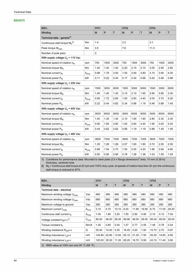
BSH070
BSH... 0701 0702 0703Winding M P T M P T M P T
Technical data - general1)
Continuous stall torque M02) Nm 1.4 2.2 3.1
Peak torque Mmax Nm 3.5 7.6 11.3
Number of pole pairs 3With supply voltage Un = 115 Vac
Nominal speed of rotation nN rpm 750 1500 3000 750 1500 3000 750 1500 3000
Nominal torque MN Nm 1.40 1.40 1.40 2.20 2.15 2.10 3.05 2.95 2.80
Nominal current IN Arms 0.98 1.76 3.00 1.50 2.90 4.80 2.10 3.90 6.30
Nominal power PN kW 0.11 0.22 0.44 0.17 0.34 0.66 0.24 0.46 0.88
With supply voltage Un = 230 Vac
Nominal speed of rotation nN rpm 1500 3000 6000 1500 3000 6000 1500 3000 6000
Nominal torque MN Nm 1.40 1.40 1.30 2.15 2.10 1.90 2.95 2.80 2.30
Nominal current IN Arms 0.95 1.72 2.80 1.50 2.80 4.40 2.00 3.70 5.20
Nominal power PN kW 0.22 0.44 0.82 0.34 0.66 1.19 0.46 0.88 1.45
With supply voltage Un = 400 Vac
Nominal speed of rotation nN rpm 3000 6000 6000 3000 6000 6000 3000 6000 6000
Nominal torque MN Nm 1.40 1.30 1.30 2.10 1.90 1.90 2.80 2.30 2.30
Nominal current IN Arms 0.90 1.60 2.80 1.50 2.60 4.40 1.90 3.00 5.20
Nominal power PN kW 0.44 0.82 0.82 0.66 1.19 1.19 0.88 1.45 1.45
With supply voltage Un = 480 Vac
Nominal speed of rotation nN rpm 3600 7200 7200 3600 7200 7200 3600 7200 7200
Nominal torque MN Nm 1.35 1.26 1.26 2.07 1.80 1.80 2.72 2.05 2.05
Nominal current IN Arms 0.88 1.54 2.70 1.50 2.50 4.20 1.85 2.65 4.60
Nominal power PN kW 0.50 0.95 0.95 0.78 1.36 1.36 1.03 1.55 1.55
1) Conditions for performance data: Mounted to steel plate (2.5 x flange dimension)2 area, 10 mm (0.39 in) thickness, centered hole.
2) M0 = Continuous stall torque at 20 rpm and 100% duty cycle; at speeds of rotation less than 20 rpm the continuous stall torque is reduced to 87%.
BSH... 0701 0702 0703Winding M P T M P T M P TTechnical data - electricalMaximum winding voltage Umax Vac 480 480 480 480 480 480 480 480 480
Maximum winding voltage Umax Vdc 680 680 680 680 680 680 680 680 680
Maximum voltage to ground Vac 280 280 280 280 280 280 280 280 280Maximum current Imax Arms 3.10 5.70 10.10 6.00 11.80 19.90 8.70 17.00 29.20
Continuous stall current I0 Arms 1.00 1.80 3.20 1.50 2.90 4.90 2.10 4.10 7.00
Voltage constant kEu-v1) Vrms 85.00 46.00 26.00 95.90 48.00 28.00 95.00 49.00 29.00
Torque constant kt Nm/A 1.40 0.80 0.44 1.47 0.77 0.45 1.48 0.78 0.44
Winding resistance R20u-v Ω 35.40 10.40 3.30 16.40 4.20 1.50 10.70 2.70 0.97
Winding inductance Lqu-v mH 144.80 42.60 13.50 83.10 21.30 7.50 55.30 14.60 4.90
Winding inductance Ldu-v mH 120.00 35.30 11.20 65.20 16.70 5.90 43.10 11.40 3.90
1) RMS value at 1000 rpm and 20 °C (68 °F).
40 0198441113837 01/2017

Technical Data
BSH100
Technical data - mechanical - with hardware version ≥RS02Maximum permissible speed of rotation nmax
rpm 8000
Rotor inertia without holding brake JM kgcm2 0.205 0.351 0.503
Rotor inertia with holding brake JM kgcm2 0.318 0.464 0.616
Mass without holding brake m kg 1.90 2.80 3.40Mass with holding brake m kg 2.10 3.00 3.50Technical data - mechanical - with hardware version <RS02Maximum permissible speed of rotation nmax
rpm 8000
Rotor inertia without holding brake JM kgcm2 0.205 0.351 0.503
Rotor inertia with holding brake JM kgcm2 0.322 0.482 0.807
Mass without holding brake m kg 2.20 2.90 3.50Mass with holding brake m kg 2.40 3.00 4.10Technical data - thermalThermal time constant tth min 35 38 51
Response threshold temperature sensor (PTC) TTK
°C(°F)
130(266)
BSH... 0701 0702 0703Winding M P T M P T M P T
1) RMS value at 1000 rpm and 20 °C (68 °F).
BSH... 1001 1002Winding M P T M P T
Technical data - general1)
Continuous stall torque M02) Nm 3.3 5.8
Peak torque Mmax Nm 9.6 18.3
Number of pole pairs 4With supply voltage Un = 115 Vac
Nominal speed of rotation nN rpm 625 1250 2500 500 1000 2000
Nominal torque MN Nm 3.20 3.15 3.00 5.70 5.50 5.20
Nominal current IN Arms 1.75 3.50 6.60 2.45 4.55 8.85
Nominal power PN kW 0.21 0.41 0.79 0.30 0.58 1.09
With supply voltage Un = 230 Vac
Nominal speed of rotation nN rpm 1250 2500 5000 1000 2000 4000
Nominal torque MN Nm 3.15 3.00 2.70 5.50 5.20 4.60
Nominal current IN Arms 1.70 3.20 5.90 2.40 4.30 7.90
Nominal power PN kW 0.41 0.79 1.41 0.58 1.09 1.93
With supply voltage Un = 400 Vac
Nominal speed of rotation nN rpm 2500 5000 5000 2000 4000 4000
Nominal torque MN Nm 3.00 2.70 2.70 5.20 4.60 4.60
Nominal current IN Arms 1.60 2.80 5.90 2.30 3.80 7.90
Nominal power PN kW 0.79 1.41 1.41 1.09 1.93 1.93
1) Conditions for performance data: Mounted to steel plate (2.5 x flange dimension)2 area, 10 mm (0.39 in) thickness, centered hole.
2) M0 = Continuous stall torque at 20 rpm and 100% duty cycle; at speeds of rotation less than 20 rpm the continuous stall torque is reduced to 87%.
0198441113837 01/2017 41

Technical Data
With supply voltage Un = 480 Vac
Nominal speed of rotation nN rpm 3000 6000 6000 2400 4800 4800
Nominal torque MN Nm 2.95 2.60 2.60 5.10 4.40 4.40
Nominal current IN Arms 1.60 2.60 5.60 2.25 3.60 7.50
Nominal power PN kW 0.93 1.63 1.63 1.28 2.21 2.21
BSH... 1001 1002Winding M P T M P TTechnical data - electricalMaximum winding voltage Umax Vac 480 480 480 480 480 480
Maximum winding voltage Umax Vdc 680 680 680 680 680 680
Maximum voltage to ground Vac 280 280 280 280 280 280Maximum current Imax Arms 6.30 12.00 25.10 9.00 17.10 35.40
Continuous stall current I0 Arms 1.80 3.50 7.30 2.50 4.80 9.90
Voltage constant kEu-v1) Vrms 115.00 60.00 29.00 146.00 77.00 37.00
Torque constant kt Nm/A 1.83 0.89 0.45 2.32 1.21 0.59
Winding resistance R20u-v Ω 13.90 3.80 0.87 8.60 2.40 0.56
Winding inductance Lqu-v mH 69.40 19.00 4.30 48.60 13.50 3.10
Winding inductance Ldu-v mH 59.50 16.30 3.70 43.20 12.00 2.80
Technical data - mechanical - with hardware version ≥RS02Maximum permissible speed of rotation nmax
rpm 6000
Rotor inertia without holding brake JM kgcm2 1.100 1.909
Rotor inertia with holding brake JM kgcm2 1.613 2.422
Mass without holding brake m kg 4.40 6.00Mass with holding brake m kg 4.90 6.50Technical data - mechanical - with hardware version <RS02Maximum permissible speed of rotation nmax
rpm 6000
Rotor inertia without holding brake JM kgcm2 1.100 1.909
Rotor inertia with holding brake JM kgcm2 2.018 2.928
Mass without holding brake m kg 4.30 5.90Mass with holding brake m kg 5.00 6.60Technical data - thermalThermal time constant tth min 44 48
Response threshold temperature sensor (PTC) TTK
°C(°F)
130(266)
1) RMS value at 1000 rpm and 20 °C (68 °F).
BSH... 1001 1002Winding M P T M P T
Technical data - general1)
1) Conditions for performance data: Mounted to steel plate (2.5 x flange dimension)2 area, 10 mm (0.39 in) thickness, centered hole.
2) M0 = Continuous stall torque at 20 rpm and 100% duty cycle; at speeds of rotation less than 20 rpm the continuous stall torque is reduced to 87%.
42 0198441113837 01/2017

Technical Data
BSH... 1003 1004Winding M P M P T
Technical data - general1)
Continuous stall torque M02) Nm 8 10
Peak torque Mmax Nm 28.3 40.5
Number of pole pairs 4With supply voltage Un = 115 Vac
Nominal speed of rotation nN rpm 500 1000 375 750 1500
Nominal torque MN Nm 7.80 7.50 10.00 9.90 9.50
Nominal current IN Arms 3.34 6.30 3.20 6.25 12.60
Nominal power PN kW 0.41 0.79 0.39 0.78 2.48
With supply voltage Un = 230 Vac
Nominal speed of rotation nN rpm 1000 2000 750 1500 3000
Nominal torque MN Nm 7.50 7.00 9.90 9.50 7.90
Nominal current IN Arms 3.27 5.90 3.20 6.10 10.90
Nominal power PN kW 0.79 1.47 0.78 1.49 2.48
With supply voltage Un = 400 Vac
Nominal speed of rotation nN rpm 2000 4000 1500 3000 3000
Nominal torque MN Nm 7.00 5.70 9.50 7.90 7.90
Nominal current IN Arms 3.10 4.90 3.20 5.30 10.90
Nominal power PN kW 1.47 2.39 1.49 2.48 2.48
With supply voltage Un = 480 Vac
Nominal speed of rotation nN rpm 2400 4800 1800 3600 3600
Nominal torque MN Nm 6.76 5.10 9.30 6.90 6.90
Nominal current IN Arms 3.00 4.40 3.15 4.80 9.80
Nominal power PN kW 1.70 2.56 1.75 2.60 2.60
1) Conditions for performance data: Mounted to steel plate (2.5 x flange dimension)2 area, 10 mm (0.39 in) thickness, centered hole.
2) M0 = Continuous stall torque at 20 rpm and 100% duty cycle; at speeds of rotation less than 20 rpm the continuous stall torque is reduced to 87%.
BSH... 1003 1004Winding M P M P TTechnical data - electricalMaximum winding voltage Umax Vac 480 480 480 480 480
Maximum winding voltage Umax Vdc 680 680 680 680 680
Maximum voltage to ground Vac 280 280 280 280 280Maximum current Imax Arms 14.70 28.30 16.80 32.30 66.30
Continuous stall current I0 Arms 3.40 6.60 3.20 6.20 12.70
Voltage constant kEu-v1) Vrms 148.00 77.00 198.00 103.00 50.00
Torque constant kt Nm/A 2.35 1.22 3.13 1.62 0.79
Winding resistance R20u-v Ω 5.30 1.43 6.70 1.81 0.45
Winding inductance Lqu-v mH 34.80 9.40 48.10 13.00 3.10
Winding inductance Ldu-v mH 30.00 8.10 39.60 10.70 2.50
1) RMS value at 1000 rpm and 20 °C (68 °F).
0198441113837 01/2017 43

Technical Data
BSH140
Technical data - mechanical - with hardware version ≥RS02Maximum permissible speed of rotation nmax
rpm 6000
Rotor inertia without holding brake JM kgcm2 2.718 3.613
Rotor inertia with holding brake JM kgcm2 3.521 4.416
Mass without holding brake m kg 7.70 9.40Mass with holding brake m kg 8.40 10.30Technical data - mechanical - with hardware version <RS02Maximum permissible speed of rotation nmax
rpm 6000
Rotor inertia without holding brake JM kgcm2 2.718 3.613
Rotor inertia with holding brake JM kgcm2 3.838 5.245
Mass without holding brake m kg 7.50 9.10Mass with holding brake m kg 8.20 9.80Technical data - thermalThermal time constant tth min 56 58
Response threshold temperature sensor (PTC) TTK
°C(°F)
130(266)
BSH... 1003 1004Winding M P M P T
1) RMS value at 1000 rpm and 20 °C (68 °F).
BSH... 1401 1402Winding M P T M P T
Technical data - general1)
Continuous stall torque M02) Nm 11.1 19.5
Peak torque Mmax Nm 27 60.1
Number of pole pairs 5With supply voltage Un = 115 Vac
Nominal speed of rotation nN rpm 375 750 1500 375 750 1500
Nominal torque MN Nm 11.00 10.95 10.60 19.10 18.60 17.10
Nominal current IN Arms 4.00 7.80 13.60 6.70 12.80 20.40
Nominal power PN kW 0.43 0.86 1.67 0.75 1.46 2.69
With supply voltage Un = 230 Vac
Nominal speed of rotation nN rpm 750 1500 3000 750 1500 3000
Nominal torque MN Nm 10.95 10.60 9.20 18.60 17.10 12.30
Nominal current IN Arms 4.00 7.60 12.10 6.60 12.00 15.20
Nominal power PN kW 0.86 1.67 2.89 1.46 2.69 3.86
With supply voltage Un = 400 Vac
Nominal speed of rotation nN rpm 1500 3000 3000 1500 3000 3000
Nominal torque MN Nm 10.60 9.20 9.20 17.10 12.30 12.30
Nominal current IN Arms 4.00 6.80 12.10 6.30 8.90 15.20
Nominal power PN kW 1.67 2.89 2.89 2.69 3.86 3.86
1) Conditions for performance data: Mounted to steel plate (2.5 x flange dimension)2 area, 10 mm (0.39 in) thickness, centered hole.
2) M0 = Continuous stall torque at 20 rpm and 100% duty cycle; at speeds of rotation less than 20 rpm the continuous stall torque is reduced to 87%.
44 0198441113837 01/2017

Technical Data
With supply voltage Un = 480 Vac
Nominal speed of rotation nN rpm 1800 3600 3600 1800 3600 3600
Nominal torque MN Nm 10.40 8.40 8.40 16.30 9.70 9.70
Nominal current IN Arms 4.00 6.30 11.15 6.10 7.10 12.20
Nominal power PN kW 1.96 3.17 3.17 3.07 3.66 3.66
BSH... 1401 1402Winding M P T M P TTechnical data - electricalMaximum winding voltage Umax Vac 480 480 480 480 480 480
Maximum winding voltage Umax Vdc 680 680 680 680 680 680
Maximum voltage to ground Vac 280 280 280 280 280 280Maximum current Imax Arms 10.80 20.80 37.10 22.40 44.10 75.20
Continuous stall current I0 Arms 4.00 7.80 13.90 6.70 13.20 22.50
Voltage constant kEu-v1) Vrms 193.00 100.00 56.00 199.00 101.00 59.00
Torque constant kt Nm/A 2.78 1.43 0.80 2.91 1.47 0.87
Winding resistance R20u-v Ω 5.30 1.41 0.44 2.32 0.60 0.21
Winding inductance Lqu-v mH 60.90 16.30 5.10 29.80 7.70 2.70
Winding inductance Ldu-v mH 55.30 14.84 4.70 27.20 7.05 2.42
Technical data - mechanical - with hardware version ≥RS02Maximum permissible speed of rotation nmax
rpm 4000
Rotor inertia without holding brake JM kgcm2 6.941 12.162
Rotor inertia with holding brake JM kgcm2 8.542 14.824
Mass without holding brake m kg 11.50 16.50Mass with holding brake m kg 12.90 18.10Technical data - mechanical - with hardware version <RS02Maximum permissible speed of rotation nmax
rpm 4000
Rotor inertia without holding brake JM kgcm2 6.941 12.162
Rotor inertia with holding brake JM kgcm2 9.210 14.480
Mass without holding brake m kg 11.20 16.10Mass with holding brake m kg 12.60 17.40Technical data - thermalThermal time constant tth min 64 74
Response threshold temperature sensor (PTC) TTK
°C(°F)
130(266)
1) RMS value at 1000 rpm and 20 °C (68 °F).
BSH... 1401 1402Winding M P T M P T
Technical data - general1)
1) Conditions for performance data: Mounted to steel plate (2.5 x flange dimension)2 area, 10 mm (0.39 in) thickness, centered hole.
2) M0 = Continuous stall torque at 20 rpm and 100% duty cycle; at speeds of rotation less than 20 rpm the continuous stall torque is reduced to 87%.
0198441113837 01/2017 45

Technical Data
BSH... 1403 1404Winding M P T M P
Technical data - general1)
Continuous stall torque M02) Nm 27.8 33.4
Peak torque Mmax Nm 90.2 131.9
Number of pole pairs 5With supply voltage Un = 115 Vac
Nominal speed of rotation nN rpm 375 750 1500 375 750
Nominal torque MN Nm 26.30 24.70 21.20 31.90 30.20
Nominal current IN Arms 8.70 15.90 17.00 10.40 19.60
Nominal power PN kW 1.03 1.94 3.33 1.25 2.37
With supply voltage Un = 230 Vac
Nominal speed of rotation nN rpm 750 1500 3000 750 1500
Nominal torque MN Nm 24.70 21.20 12.90 30.20 26.30
Nominal current IN Arms 8.30 13.90 10.30 10.00 17.40
Nominal power PN kW 1.94 3.33 4.05 2.37 4.13
With supply voltage Un = 400 Vac
Nominal speed of rotation nN rpm 1500 3000 3000 1500 3000
Nominal torque MN Nm 21.20 12.90 12.90 26.30 16.10
Nominal current IN Arms 7.30 8.70 10.30 9.00 11.00
Nominal power PN kW 3.33 4.05 4.05 4.13 5.06
With supply voltage Un = 480 Vac
Nominal speed of rotation nN rpm 1800 3600 3600 1800 3600
Nominal torque MN Nm 19.70 9.10 9.10 24.50 11.10
Nominal current IN Arms 6.90 6.20 7.30 8.50 7.70
Nominal power PN kW 3.71 3.43 3.43 4.62 4.19
1) Conditions for performance data: Mounted to steel plate (2.5 x flange dimension)2 area, 10 mm (0.39 in) thickness, centered hole.
2) M0 = Continuous stall torque at 20 rpm and 100% duty cycle; at speeds of rotation less than 20 rpm the continuous stall torque is reduced to 87%.
BSH... 1403 1404Winding M P T M PTechnical data - electricalMaximum winding voltage Umax Vac 480 480 480 480 480
Maximum winding voltage Umax Vdc 680 680 680 680 680
Maximum voltage to ground Vac 280 280 280 280 280Maximum current Imax Arms 31.30 61.00 81.30 47.80 95.60
Continuous stall current I0 Arms 9.00 17.60 22.30 10.70 21.30
Voltage constant kEu-v1) Vrms 205.00 105.00 78.00 208.00 104.00
Torque constant kt Nm/A 3.09 1.58 1.25 3.12 1.57
Winding resistance R20u-v Ω 1.52 0.40 0.22 1.12 0.28
Winding inductance Lqu-v mH 20.20 5.30 2.70 16.30 4.10
Winding inductance Ldu-v mH 18.40 4.84 3.00 14.80 3.69
1) RMS value at 1000 rpm and 20 °C (68 °F).
46 0198441113837 01/2017

Technical Data
BSH205
Technical data - mechanical - with hardware version ≥RS02Maximum permissible speed of rotation nmax
rpm 4000
Rotor inertia without holding brake JM kgcm2 17.383 22.604
Rotor inertia with holding brake JM kgcm2 21.559 26.794
Mass without holding brake m kg 21.90 27.00Mass with holding brake m kg 24.00 29.30Technical data - mechanical - with hardware version <RS02Maximum permissible speed of rotation nmax
rpm 4000
Rotor inertia without holding brake JM kgcm2 17.383 22.604
Rotor inertia with holding brake JM kgcm2 23.440 29.200
Mass without holding brake m kg 21.30 26.30Mass with holding brake m kg 23.20 28.40Technical data - thermalThermal time constant tth min 79 83
Response threshold temperature sensor (PTC) TTK
°C(°F)
130(266)
BSH... 1403 1404Winding M P T M P
1) RMS value at 1000 rpm and 20 °C (68 °F).
BSH... 2051 2052 2053Winding M P M P M P
Technical data - general1)
Continuous stall torque M02) Nm 36.90 64.90 94.40
Peak torque Mmax Nm 110 220 330
Number of pole pairs 5With supply voltage Un = 115 Vac
Nominal speed of rotation nN rpm 375 750 250 500 250 500
Nominal torque MN Nm 34.40 31.90 63.50 61.60 89.90 84.90
Nominal current IN Arms 10.50 18.80 13.00 25.40 16.30 30.80
Nominal power PN kW 1.35 2.51 1.66 3.23 2.35 4.45
With supply voltage Un = 230 Vac
Nominal speed of rotation nN rpm 750 1500 500 1000 500 1000
Nominal torque MN Nm 31.90 27.00 61.60 56.00 84.90 74.40
Nominal current IN Arms 10.10 16.50 12.60 24.00 16.00 27.90
Nominal power PN kW 2.51 4.24 3.23 5.86 4.45 7.79
With supply voltage Un = 400 Vac
Nominal speed of rotation nN rpm 1500 3000 1000 2000 1000 2000
Nominal torque MN Nm 27.00 17.50 56.00 38.10 74.40 50.70
Nominal current IN Arms 9.20 11.50 11.50 17.80 15.00 20.40
Nominal power PN kW 4.24 5.50 5.86 7.98 7.79 10.62
1) Conditions for performance data: Mounted to steel plate (2.5 x flange dimension)2 area, 10 mm (0.39 in) thickness, centered hole.
2) M0 = Continuous stall torque at 20 rpm and 100% duty cycle; at speeds of rotation less than 20 rpm the continuous stall torque is reduced to 87%.
0198441113837 01/2017 47

Technical Data
With supply voltage Un = 480 Vac
Nominal speed of rotation nN rpm 1800 3600 1200 2400 1200 2400
Nominal torque MN Nm 25.10 13.80 53.10 28.40 70.00 40.20
Nominal current IN Arms 8.80 9.40 10.90 13.80 14.50 16.70
Nominal power PN kW 4.73 5.20 6.67 7.14 8.80 10.10
BSH... 2051 2052 2053Winding M P M P M PTechnical data - electricalMaximum winding voltage Umax Vac 480 480 480 480 480 480
Maximum winding voltage Umax Vdc 680 680 680 680 680 680
Maximum voltage to ground Vac 280 280 280 280 280 280Maximum current Imax Arms 45.20 87.20 49.60 96.80 68.00 136.10
Continuous stall current I0 Arms 10.90 21.00 13.20 25.70 16.60 33.20
Voltage constant kEu-v1) Vrms 200.00 104.00 314.00 161.00 344.00 172.00
Torque constant kt Nm/A 3.10 1.60 5.04 2.58 5.50 2.76
Winding resistance R20u-v Ω 1.10 0.30 1.10 0.30 0.80 0.20
Winding inductance Lqu-v mH 21.90 5.90 21.20 5.60 17.10 4.30
Winding inductance Ldu-v mH 20.80 5.60 20.00 5.20 16.10 4.00
Technical data - mechanical - with hardware version <RS02Maximum permissible speed of rotation nmax
rpm 3800
Rotor inertia without holding brake JM kgcm2 71.40 129 190
Rotor inertia with holding brake JM kgcm2 87.40 145 206
Mass without holding brake m kg 35.00 50.00 67.00Mass with holding brake m kg 38.60 53.60 70.60Technical data - thermalThermal time constant tth min 73 88 101
Response threshold temperature sensor (PTC) TTK
°C(°F)
130(266)
1) RMS value at 1000 rpm and 20 °C (68 °F).
BSH... 2051 2052 2053Winding M P M P M P
Technical data - general1)
1) Conditions for performance data: Mounted to steel plate (2.5 x flange dimension)2 area, 10 mm (0.39 in) thickness, centered hole.
2) M0 = Continuous stall torque at 20 rpm and 100% duty cycle; at speeds of rotation less than 20 rpm the continuous stall torque is reduced to 87%.
48 0198441113837 01/2017

Technical Data
Encoder
The motors are equipped with a SinCos encoder. The drive can access the electronic nameplate via the Hiperface interface for commissioning.The signals meet the PELV requirements.
SKS36 SingleturnThis motor encoder measures an absolute value within one revolution at start-up and continues to count incrementally from this point.
SKM36 MultiturnThis motor encoder measures an absolute value within 4096 revolutions at start-up and continues to count incrementally from this point.
Characteristic ValueResolution in increments Depending on evaluation Resolution per revolution 128 sin/cos periodsMeasuring range absolute 1 revolution
Accuracy of the digital absolute value1) ±0.0889°
Accuracy of the incremental position ±0.0222°Signal shape SinusoidalSupply voltage 7 ... 12 VdcMaximum supply current 60 mA (without load)Maximum angular acceleration 200000 rad/s2
1) Depending on the evaluation through the drive, the accuracy may be increased by including the incremental position in the calculation of the absolute value. In this case, the accuracy corresponds to the incremental position.
Characteristic ValueResolution in increments Depending on evaluation Resolution per revolution 128 sin/cos periodsMeasuring range absolute 4096 revolutions
Accuracy of the digital absolute value1) ±0.0889°
Accuracy of the incremental position ±0.0222°Signal shape SinusoidalSupply voltage 7 ... 12 VdcMaximum supply current 60 mA (without load)Maximum angular acceleration 200000 rad/s2
1) Depending on the evaluation through the drive, the accuracy may be increased by including the incremental position in the calculation of the absolute value. In this case, the accuracy corresponds to the incremental position.
0198441113837 01/2017 49

Technical Data
SEK37 SingleturnThis motor encoder measures an absolute value within one revolution at start-up and continues to count incrementally from this point.
SEL37 MultiturnThis motor encoder measures an absolute value within 4096 revolutions at start-up and continues to count incrementally from this point.
Characteristic ValueResolution in increments Depending on evaluation Resolution per revolution 16 sin/cos periodsMeasuring range absolute 1 revolutionAccuracy of position ± 0.08°Signal shape SinusoidalSupply voltage 7 ... 12 VdcMaximum supply current 50 mA (without load)
Characteristic ValueResolution in increments Depending on evaluation Resolution per revolution 16 sin/cos periodsMeasuring range absolute 4096 revolutionsAccuracy of position ± 0.08°Signal shape SinusoidalSupply voltage 7 ... 12 VdcMaximum supply current 50 mA (without load)
50 0198441113837 01/2017

Technical Data
Holding Brake
Hardware version ≥RS02:
Hardware version <RS02:
BSH... 040 055 070 1001, 1002
1003, 1004
1401 1402 1403, 1404
205
Holding torque1) Nm (lb•in)
0.4 (3.54)
0.8 (7.08)
3.0 (26.6)
5.5 (48.7)
10 (88.5)
18 (159)
23 (204)
33 (292)
80 (708)
Opening time ms 24 16 80 70 90 100 100 200 200Coupling time ms 13 21 17 30 25 50 40 60 50Nominal voltage Vdc 24
+15%-15%
24+6%-10%
24+5%-15%
24+5%-15%
24+5%-15%
24+5%-15%
24+5%-15%
24+5%-15%
24+6%-10%
Nominal power (electrical pull-in power)
W 5.8 10 7 12 18 18 19 22.5 40
Maximum speed of rotation during braking of moving loads
rpm 3000 3000 3000 3000 3000 3000 3000 3000 3000
Maximum number of decelerations during braking of moving loads and 3000 rpm
500 500 500 500 500 500 500 500 500
Maximum number of decelerations during braking of moving loads per hour (at even distribution)
20 20 20 20 20 20 20 20 20
Maximum kinetic energy that can be transformed into heat per deceleration during braking of moving loads
J 10 120 130 150 150 550 550 850 21000
1) The holding brake is broken-in at the factory. If the holding brake is not used for an extended period of time, parts of the holding brake may corrode. Corrosion reduces the holding torque.
BSH... 055 0701, 0702
0703 1001, 1002, 1003
1004 1401, 1402
1403, 1404
205
Holding torque1) Nm (lb•in)
0.8 (7.08)
2 (17.7) 3 (26.6) 9 (79.7) 12 (106) 23 (204) 36 (319) 80 (708)
Opening time ms 12 12 35 42 64 84 63 110Coupling time ms 6 6 15 38 37 61 73 140Nominal voltage Vdc 24
+6%-10%
24+6%-10%
24+6%-10%
24+6%-10%
24+6%-10%
24+6%-10%
24+6%-10%
24+6%-10%
Nominal power (electrical pull-in power)
W 10 10 12 18 17 24 26 40
1) The holding brake is broken-in at the factory. If the holding brake is not used for an extended period of time, parts of the holding brake may corrode. Corrosion reduces the holding torque.
0198441113837 01/2017 51

Technical Data
Certifications
Product Certifications
Conditions for UL 1004-1, UL 1004-6 and CSA 22.2 No. 100
PELV Power SupplyUse only power supply units that are approved for overvoltage category III.
WiringUse at least 60/75 °C (140/167 °F) copper conductors.
Certified by Assigned numberUL File E208613
52 0198441113837 01/2017
BSHInstallation 0198441113837 01/2017
Installation
Chapter 3Installation
This equipment has been designed to operate outside of any hazardous location. Only install this equipment in zones known to be free of a hazardous atmosphere.
Motors are very heavy relative to their size. The great mass of the motor can cause injuries and damage. The motor may move, tip and fall as a result of incorrect or insufficient mounting.
Motors can generate strong local electrical and magnetic fields. This can cause interference in electromag-netically sensitive devices.
DANGERELECTRIC SHOCK CAUSED BY INSUFFICIENT GROUNDING Verify compliance with all local and national electrical code requirements as well as all other applicable
regulations with respect to grounding of the entire drive system. Ground the drive system before applying voltage. Do not use conduits as protective ground conductors; use a protective ground conductor inside the
conduit. The cross section of the protective ground conductor must comply with the applicable standards. Do not consider cable shields to be protective ground conductors.Failure to follow these instructions will result in death or serious injury.
DANGERELECTRIC SHOCK OR UNINTENDED EQUIPMENT OPERATION Keep foreign objects (such as chips, screws or wire clippings) from getting into the product. Verify the correct seating of seals and cable entries in order to avoid contamination such as deposits
and humidity.Failure to follow these instructions will result in death or serious injury.
DANGERPOTENTIAL FOR EXPLOSIONInstall and use this equipment in non-hazardous locations only.Failure to follow these instructions will result in death or serious injury.
WARNINGHEAVY AND/OR FALLING PARTS Use a suitable crane or other suitable lifting gear for mounting the motor if this is required by the weight
of the motor. Use the necessary personal protective equipment (for example, protective shoes, protective glasses
and protective gloves). Mount the motor so that it cannot come loose (use of securing screws with appropriate tightening
torque), especially in cases of fast acceleration or continuous vibration.Failure to follow these instructions can result in death, serious injury, or equipment damage.
0198441113837 01/2017 53

Installation
The metal surfaces of the product may exceed 70 °C (158 °F) during operation.
What Is in This Chapter?This chapter contains the following sections:
WARNINGELECTROMAGNETIC FIELDS Keep persons with electronic medical implants, such as pacemakers, away from the motor. Do not place electromagnetically sensitive devices in the vicinity of the motor.Failure to follow these instructions can result in death, serious injury, or equipment damage.
WARNINGHOT SURFACES Avoid unprotected contact with hot surfaces. Do not allow flammable or heat-sensitive parts in the immediate vicinity of hot surfaces. Verify that the heat dissipation is sufficient by performing a test run under maximum load conditions.Failure to follow these instructions can result in death, serious injury, or equipment damage.
WARNINGIMPROPER APPLICATION OF FORCES Do not use the motor as a step to climb into or onto the machine. Do not use the motor as a load-bearing part. Use hazard labels and guards on your machine to help prevent the improper application of forces on
the motor.Failure to follow these instructions can result in death, serious injury, or equipment damage.
Section Topic Page3.1 Electromagnetic Compatibility (EMC) 553.2 Mechanical Installation 573.3 Electrical Installation 66
54 0198441113837 01/2017

Installation
Electromagnetic Compatibility (EMC)
Section 3.1Electromagnetic Compatibility (EMC)
Electromagnetic Compatibility (EMC)
The measures for electromagnetic compatibility (EMC) are intended to minimize electromagnetic interference of the device and interference caused by the device that affects the environment. Such measures include measures to reduce interference and emission as well as to increase immunity.Electromagnetic compatibility hinges to a great extent on the individual components used in the system. The EMC measures described in this manual may help to comply with the requirements of IEC 61800-3. You must comply with all EMC regulations of the country in which the product is operated. Also, respect any special EMC regulations that may apply at the installation site (for example, residential environments or airports).Signal interference can cause unexpected responses of the drive system and of other equipment in the vicinity of the drive system.
Motor and Encoder CablesIn terms of EMC, motor cables are especially critical since they are particularly prone to causing interference.When planning the wiring, take into account the fact that the motor cable must be routed separately. The motor cable must be separate from mains cables or signal cables (for example, limit switches). Use only pre-assembled cables or cables that comply with the specifications and implement the EMC measures described below.
WARNINGSIGNAL AND EQUIPMENT INTERFERENCE Install the wiring in accordance with the EMC requirements described in the present document. Verify compliance with the EMC requirements described in the present document. Verify compliance with all EMC regulations and requirements applicable in the country in which the
product is to be operated and with all EMC regulations and requirements applicable at the installation site.
Failure to follow these instructions can result in death, serious injury, or equipment damage.
EMC measures EffectKeep cables as short as possible. Do not install unnecessary cable loops. Use short cables from the central grounding point in the control cabinet to the external ground connection.
Reduces capacitive and inductive interference.
Ensure that there is a ground connection between the motor flange and the mounting surface on the machine (no paint, oil and grease or any insulating material between the motor flange and the mounting surface on the machine).
Reduces emissions, increases immunity.
Connect large surface areas of cable shields, use cable clamps and ground straps.
Reduces emissions.
Do not install switching elements in motor cables or encoder cables.
Reduces interference.
Route the motor cable separately from mains cables and signal cables (for example, for limit switches), for example by using shielding plates or by keeping the cables apart from each other at a distance of at least 20 cm (5.08 in).
Reduces mutual interference.
Route the motor cable and encoder cable without cutting them.(1)
Reduces emission.
(1) If a cable is cut for the installation, take appropriate measures for uninterrupted shielding (such as a metal housing) at the point of the cut. Connect a large area of the cable shield to the metal housing at both ends of the cut.
0198441113837 01/2017 55

Installation
Pre-Assembled Connection Cables (Accessories)Using pre-assembled cables helps to reduce the possibility of wiring errors. See chapter Accessories and Spare Parts (see page 83).
Equipotential Bonding ConductorsPotential differences can result in excessive currents on the cable shields. Use equipotential bonding conductors to reduce currents on the cable shields.
1Multipoint grounding is permissible if connections are made to an equipotential ground plane dimensioned to help avoid cable shield damage in the event of power system short-circuit currents.
WARNINGUNINTENDED EQUIPMENT OPERATION Use shielded cables for all fast I/O, analog I/O and communication signals. Ground cable shields for all analog I/O, fast I/O and communication signals at a single point1. Route communication and I/O cables separately from power cables.Failure to follow these instructions can result in death, serious injury, or equipment damage.
56 0198441113837 01/2017

Installation
Mechanical Installation
Section 3.2Mechanical Installation
What Is in This Section?This section contains the following topics:
Topic PageBefore Mounting 58Cable Specifications 60Mounting The Motor 63Installation and Connection of IP67 Kit (Accessory) 65
0198441113837 01/2017 57

Installation
Before Mounting
Inspecting The Product Verify the product version by means of the type code on the nameplate. See chapter Nameplate
(see page 13) and chapter Type Code (see page 15). Prior to mounting, inspect the product for visible damage.Damaged products may cause electric shock or unintended equipment operation.
Contact your local Schneider Electric sales office if you detect any damage whatsoever to the products.
Inspecting the Holding Brake (Option)See chapter Inspecting/Breaking In the Holding Brake (see page 58).
Cleaning the ShaftThe shaft extensions are factory-treated with an anti-corrosive. If output components are glued to the shaft, the anti-corrosive must be removed and the shaft cleaned. If required, use a grease removal agent as specified by the glue manufacturer. If the glue manufacturer does not provide information on grease removal, acetone may be used. Remove the anti-corrosive. Avoid direct contact of the skin and the sealing parts with the anti-corrosive
or the cleaning agent.
Mounting Surface for FlangeThe mounting surface must be stable, clean, deburred and low-vibration. Ensure that the mounting surface is itself grounded, and that a potential exists between the motor flange and the mounting surface.
Verify that the mounting surface meets the requirements in terms of dimensions and tolerances in this document.
DANGERELECTRIC SHOCK OR UNINTENDED EQUIPMENT OPERATION Do not use damaged products. Keep foreign objects (such as chips, screws or wire clippings) from getting into the product.Failure to follow these instructions will result in death or serious injury.
DANGERELECTRIC SHOCK CAUSED BY INSUFFICIENT GROUNDING Verify compliance with all local and national electrical code requirements as well as all other applicable
regulations with respect to grounding of the entire drive system. Ground the drive system before applying voltage. Do not use conduits as protective ground conductors; use a protective ground conductor inside the
conduit. The cross section of the protective ground conductor must comply with the applicable standards. Do not consider cable shields to be protective ground conductors.Failure to follow these instructions will result in death or serious injury.
58 0198441113837 01/2017
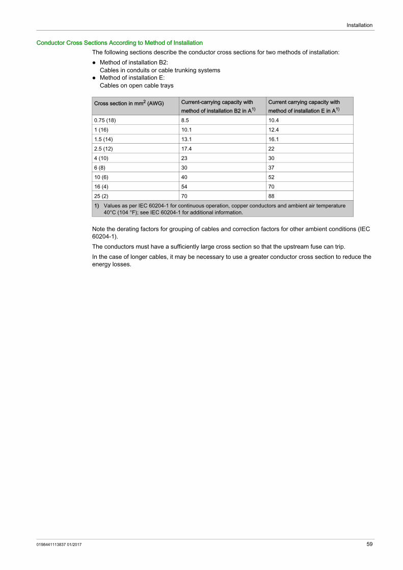
Installation
Conductor Cross Sections According to Method of InstallationThe following sections describe the conductor cross sections for two methods of installation: Method of installation B2:
Cables in conduits or cable trunking systems Method of installation E:
Cables on open cable trays
Note the derating factors for grouping of cables and correction factors for other ambient conditions (IEC 60204-1).The conductors must have a sufficiently large cross section so that the upstream fuse can trip.In the case of longer cables, it may be necessary to use a greater conductor cross section to reduce the energy losses.
Cross section in mm2 (AWG) Current-carrying capacity with method of installation B2 in A1)
Current carrying capacity with method of installation E in A1)
0.75 (18) 8.5 10.41 (16) 10.1 12.41.5 (14) 13.1 16.12.5 (12) 17.4 224 (10) 23 306 (8) 30 3710 (6) 40 5216 (4) 54 7025 (2) 70 881) Values as per IEC 60204-1 for continuous operation, copper conductors and ambient air temperature
40°C (104 °F); see IEC 60204-1 for additional information.
0198441113837 01/2017 59

Installation
Cable Specifications
Using pre-assembled cables helps to reduce the possibility of wiring errors. See chapter Accessories and Spare Parts (see page 83).The genuine accessories have the following properties:
Motor Cable With Connector
Motor Cable Without Connector
VW3... M5100R••• M5101R••• M5102R••• M5103R••• M5105R••• M5104R•••Cable jacket, insulation PUR orange (RAL 2003),
TPMPUR orange (RAL 2003), polypropylene (PP)
Capacitance power wiresWire/wireWire/shield
pF/mpF/m
80145
80135
80150
90150
85150
100160
Number of contacts (shielded)
(4 x 1 mm2 +2 x (2 x 0.75 mm2))
(4 x 1.5 mm2 +(2 x 1 mm2))
(4 x 2.5 mm2 +(2 x 1 mm2))
(4 x 4 mm2 +(2 x 1 mm2))
(4 x 6 mm2 +(2 x 1 mm2))
(4 x 10 mm2 +(2 x 1 mm2))
Connector motor side 8-pin circular Y-TEC 8-pin circular M23 8-pin circular M40Connector drive side OpenCable diameter mm
(in)11 ± 0.3(0.43 ± 0.01)
12 ± 0.2(0.47 ± 0.01)
14.3 ± 0.3(0.55 ± 0.01)
16.3 ± 0.3(0.64 ± 0.01)
18.8 ± 0.4(0.74 ± 0.02)
23.5 ± 0.6(0.93 ± 0.02)
Minimum bend radius with permanently installed connection
10 times the cable diameter
5 times the cable diameter
Minimum bend radius with flexible installation
10 times the cable diameter
7.5 times the cable diameter 10 times the cable diameter
Nominal voltageMotor phasesHolding brake
VV
10001000
600300
Maximum orderable length
m (ft) 25 (82) 75 (246)
Permissible temperature range during operation with permanently installed connection
°C (°F) -40 ... 80 (-40 ... 176)
Permissible temperature range during operation with flexible installation
°C (°F) -20 ... 60 (-4 ... 140) -20 ... 80 (-4 ... 176)
Certifications / declaration of conformity
CE, DESINA
VW3... M5300R••• M5301R••• M5302R••• M5303R••• M5305R••• M5304R•••Cable jacket, insulation PUR orange (RAL 2003),
TPMPUR orange (RAL 2003), polypropylene (PP)
Capacitance power wiresWire/wireWire/shield
pF/mpF/m
80145
80135
80150
90150
85150
100160
Number of contacts (shielded)
(4 x 1 mm2 +2 x (2 x 0.75 mm2))
(4 x 1.5 mm2 +(2 x 1 mm2))
(4 x 2.5 mm2 +(2 x 1 mm2))
(4 x 4 mm2 +(2 x 1 mm2))
(4 x 6 mm2 +(2 x 1 mm2))
(4 x 10 mm2 +(2 x 1 mm2))
Connector motor side OpenConnector drive side OpenCable diameter mm
(in)11 ± 0.3(0.43 ± 0.01)
12 ± 0.2(0.47 ± 0.01)
14.3 ± 0.3(0.55 ± 0.01)
16.3 ± 0.3(0.64 ± 0.01)
18.8 ± 0.4(0.74 ± 0.02)
23.5 ± 0.6(0.93 ± 0.02)
Minimum bend radius with permanently installed connection
10 times the cable diameter
5 times the cable diameter
60 0198441113837 01/2017

Installation
Encoder Cable With and Without Connectors
Minimum bend radius with flexible installation
10 times the cable diameter
7.5 times the cable diameter 10 times the cable diameter
Nominal voltageMotor phasesHolding brake
V10001000
600300
Maximum orderable length
m (ft) 100 (328)
Permissible temperature range during operation with permanently installed connection
°C (°F) -40 ... 80 (-40 ... 176)
Permissible temperature range during operation with flexible installation
°C (°F) -20 ... 60 (-4 ... 140) -20 ... 80 (-4 ... 176)
Certifications / declaration of conformity
CE, c-UR-us, DESINA
VW3... M5300R••• M5301R••• M5302R••• M5303R••• M5305R••• M5304R•••
VW3... M8100R••• M8102R••• M8222R•••Cable jacket, insulation PUR green (RAL 6018), polypropylene (PP)Capacitance pF/m Approx. 135 (wire/wire)Number of contacts (shielded) (3 x 2 x 0.14 mm2 + 2 x 0.34 mm2)Connector motor side 12-pin circular Y-TEC 12-pin circular M23 OpenConnector drive side 10-pin RJ45 10-pin RJ45 OpenCable diameter mm
(in)6.8 ± 0.2(0.27 ± 0.1)
Minimum bend radius mm(in)
68(2.68)
Nominal voltage V 300Maximum orderable length m
(ft)25(82)
75(246)
100(328)
Permissible temperature range during operation with permanently installed connection
°C (°F) -40 ... 80 (-40 ... 176)
Permissible temperature range during operation with flexible installation
°C (°F) -20 ... 80 (-4 ... 176)
Certifications / declaration of conformity
DESINA c-UR-us, DESINA
0198441113837 01/2017 61

Installation
Clearance For Connectors
Straight connectors Angular connectors
Dimensions Motor connectorsstraight
Encoder connectorstraight
M23 M40 M23D mm (in) 28 (1.1) 46 (1.81) 26 (1.02)LS mm (in) 76 (2.99) 100 (3.94) 51 (2.01)LR mm (in) 117 (4.61) 155 (6.1) 76 (2.99)LC mm (in) 100 (3.94) 145 (5.71) 60 (2.36)LM mm (in) 40 (1.57) 54 (2.13) 23 (0.91)
Dimensions Motor connectorsangular
Encoder connectorangular
Y-TEC M23 M40 Y-TEC M23D mm (in) 18.7 (0.74) 28 (1.1) 46 (1.81) 18.7 (0.74) 26 (1.02)LS mm (in) 42 (1.65) 76 (2.99) 100 (3.94) 42 (1.65) 51 (2.01)LR mm (in) 100 (3.94) 132 (5.2) 191 (7.52) 100 (3.94) 105 (4.13)LC mm (in) 89 (3.50) 114 (4.49) 170 (6.69) 89 (3.50) 89 (3.5)LM mm (in) 58 (2.28) 55 (2.17) 91 (3.58) 58 (2.28) 52 (2.05)
62 0198441113837 01/2017

Installation
Mounting The Motor
Electrostatic discharge to the shaft may cause incorrect operation of the encoder system and result in unanticipated motor movements and damage to the bearing.
If the permissible environmental conditions are not respected, external substances from the environment may penetrate the product and cause unintended movement or equipment damage.
The metal surfaces of the product may exceed 70 °C (158 °F) during operation.
Mounting PositionThe following mounting positions are defined and permissible as per IEC 60034-7:
MountingWhen the motor is mounted to the mounting surface, it must be accurately aligned axially and radially and make even contact with the mounting surface. All mounting screws must be tightened with the specified tightening torque. No uneven mechanical load must be applied when the mounting screws are tightened. See chapter Technical Data (see page 17) for data, dimensions and degrees of protection (IP).
WARNINGUNINTENDED MOVEMENT CAUSED BY ELECTROSTATIC DISCHARGEUse conductive components such as antistatic belts or other suitable measures to avoid static charge by motion.Failure to follow these instructions can result in death, serious injury, or equipment damage.
WARNINGUNINTENDED MOVEMENT Verify that the environmental conditions are respected. Do not allow seals to run dry. Keep liquids from getting to the shaft bushing Do not expose the shaft sealing rings and cable entries of the motor to the direct spray of a pressure
washer.Failure to follow these instructions can result in death, serious injury, or equipment damage.
WARNINGHOT SURFACES Avoid unprotected contact with hot surfaces. Do not allow flammable or heat-sensitive parts in the immediate vicinity of hot surfaces. Verify that the heat dissipation is sufficient by performing a test run under maximum load conditions.Failure to follow these instructions can result in death, serious injury, or equipment damage.
0198441113837 01/2017 63

Installation
Mounting Output ComponentsOutput components such as pulleys and couplings must be mounted with suitable equipment and tools. Motor and output component must be accurately aligned both axially and radially. If the motor and the output component are not accurately aligned, this will cause runout and premature wear.The maximum axial and radial forces acting on the shaft must not exceed the maximum shaft load values specified, see chapter Shaft-specific Data (see page 34).If the maximum permissible forces at the motor shaft are exceeded, this will result in premature wear of the bearing or shaft breakage.
WARNINGUNINTENDED EQUIPMENT OPERATION DUE TO MECHANICAL DAMAGE TO THE MOTOR Do not exceed the maximum permissible axial and radial forces at the motor shaft. Protect the motor shaft from impact. Do not exceed the maximum permissible axial force when pressing components onto the motor shaft.Failure to follow these instructions can result in death, serious injury, or equipment damage.
64 0198441113837 01/2017
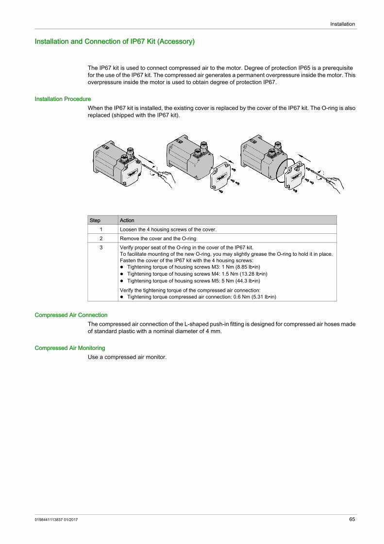
Installation
Installation and Connection of IP67 Kit (Accessory)
The IP67 kit is used to connect compressed air to the motor. Degree of protection IP65 is a prerequisite for the use of the IP67 kit. The compressed air generates a permanent overpressure inside the motor. This overpressure inside the motor is used to obtain degree of protection IP67.
Installation ProcedureWhen the IP67 kit is installed, the existing cover is replaced by the cover of the IP67 kit. The O-ring is also replaced (shipped with the IP67 kit).
Compressed Air ConnectionThe compressed air connection of the L-shaped push-in fitting is designed for compressed air hoses made of standard plastic with a nominal diameter of 4 mm.
Compressed Air MonitoringUse a compressed air monitor.
Step Action1 Loosen the 4 housing screws of the cover.2 Remove the cover and the O-ring3 Verify proper seat of the O-ring in the cover of the IP67 kit.
To facilitate mounting of the new O-ring, you may slightly grease the O-ring to hold it in place.Fasten the cover of the IP67 kit with the 4 housing screws: Tightening torque of housing screws M3: 1 Nm (8.85 lb•in) Tightening torque of housing screws M4: 1.5 Nm (13.28 lb•in) Tightening torque of housing screws M5: 5 Nm (44.3 lb•in)
Verify the tightening torque of the compressed air connection: Tightening torque compressed air connection: 0.6 Nm (5.31 lb•in)
0198441113837 01/2017 65

Installation
Electrical Installation
Section 3.3Electrical Installation
What Is in This Section?This section contains the following topics:
Topic PageConnectors and Connector Assignments 67Power and Encoder Connection 71Holding Brake Connection 77
66 0198441113837 01/2017

Installation
Connectors and Connector Assignments
Connection Overview
CN1 Motor ConnectionMotor connector for connection of the motor phases and the holding brake.
See chapter Connectors (see page 85) for suitable mating connectors.
Overview of the connectionsBSH040 BSH055 BSH070 BSH100
BSH1401, BSH1402M, BSH1402P, BSH1403M, BSH1403P, BSH1404M
BSH1402T, BSH1403T, BSH1404P BSH205
CN1 Motor connectionCN2 Encoder connection
Y-TEC M23 M40
0198441113837 01/2017 67

Installation
The signals of the holding brake meet the PELV requirements.
CN2 encoder connection Y-TECEncoder connector for connection of the SinCos encoder (singleturn and multiturn)
See chapter Connectors (see page 85) for suitable mating connectors.The signals meet the PELV requirements.
Pin Meaning Accessory cableWire color and wire number
U Motor phase U BK, L1V Motor phase V BK, L2W Motor phase W BK, L3PE Protective ground conductor GN/YE+ Supply voltage holding brake 24 Vdc WH or BK 5- Reference potential holding brake 0 Vdc GY or BK 6SHLD Shield (to connector housing) -
Pin Signal Meaning Pair1) Accessory cableWire color
1 COS_OUT Cosine signal 2 GN2 REFCOS_OUT Reference for cosine signal, 2.5V 2 YE3 SIN_OUT Sine signal 1 WH4 REFSIN_OUT Reference for sine signal, 2.5 V 1 BN5 DATA+ Receive data, transmit data 3 GY6 DATA- Receive data and transmit data, inverted 3 PK7 ENC+10V 7 ... 12 V supply voltage 4 RD8 ENC_0V Reference potential2) 4 BL
SHLD Shield (to connector housing)1) Signal pairs must be twisted2) The ENC_0V connection of the supply voltage has no connection to the encoder housing.
68 0198441113837 01/2017

Installation
CN2 encoder connection M23Encoder connector for connection of the SinCos encoder (singleturn and multiturn)
See chapter Connectors (see page 85) for suitable mating connectors.The signals meet the PELV requirements.
Motor connection terminal boxTerminal box for connection of the motor phases and the holding brake
Pin Signal Meaning Pair1) Accessory cableWire color
1 PTC Temperature sensor 6 BK2 PTC Temperature sensor 5 GY/PK4 REFSIN_OUT Reference for sine signal, 2.5 V 3 BN5 REFCOS_OUT Reference for cosine signal, 2.5V 2 YE6 DATA+ Receive data, transmit data 1 GY7 DATA- Receive data and transmit data,
inverted1 PK
8 SIN_OUT Sine signal 3 WH9 COS_OUT Cosine signal 2 GN10 ENC+10V 7 ... 12 V supply voltage 4 RD11 ENC_0V Reference potential2) 4 BL
SHLD Shield (to connector housing)1) Signal pairs must be twisted2) The ENC_0V connection of the supply voltage has no connection to the encoder housing.
0198441113837 01/2017 69

Installation
The signals of the holding brake meet the PELV requirements.
Pin Assignment MeaningU U Motor phase U
PE Protective ground conductorW W Motor phase WV V Motor phase V1 BR+ Supply voltage holding brake 24 Vdc2 BR- Reference potential holding brake3 Reserved Reserved4 Reserved Reserved
SHLD Shield (on housing)
70 0198441113837 01/2017

Installation
Power and Encoder Connection
High voltages may be present at the motor connection. The motor itself generates voltage when the motor shaft is rotated. AC voltage can couple voltage to unused conductors in the motor cable.
The motor is designed for operation via a drive. Connecting the motor directly to AC voltage will damage the motor and can cause fires and initiate an explosion.
Drive systems may perform unintended movements if unapproved combinations of drive and motor are used. Even if motors are similar, different adjustment of the encoder system may be a source of hazards. Even if the connectors for motor connection and encoder connection match mechanically, this does not imply that the motor is approved for use.
See chapter Approved Drives (see page 22) for approved drives.
Protective Ground Conductor Connection
Ground the motor via a grounding screw if grounding via the flange and the protective ground conductor of the motor cable is not sufficient. Use parts with suitable corrosion protection. Note the required tightening torque and the property class of the grounding screw, see chapter Tightening Torque and Property Class Of Screws Used (see page 19).
DANGERELECTRIC SHOCK Verify that no voltage is present prior to performing any type of work on the drive system. Block the motor shaft to prevent rotation prior to performing any type of work on the drive system. Insulate both ends of unused conductors of the motor cable. Only touch the motor shaft or the mounted output components if all power has been disconnected. Verify compliance with all local and national electrical code requirements as well as all other applicable
regulations with respect to grounding of all equipment.Failure to follow these instructions will result in death or serious injury.
DANGERPOTENTIAL FOR EXPLOSIONOnly connect the motor to a matching, approved drive in the way described in the present documentation.Failure to follow these instructions will result in death or serious injury.
WARNINGUNINTENDED MOVEMENTOnly use approved combinations of drive and motor.Failure to follow these instructions can result in death, serious injury, or equipment damage.
BSH040 BSH055 ... BSH205
0198441113837 01/2017 71

Installation
Assembling CablesInsulate unused wires individually. Note the EMC requirements for motor cables and encoder cables, see chapter Electromagnetic
Compatibility (EMC) (see page 55). Use equipotential bonding conductors for equipotential bonding.
Assembling Motor Cables With Y-TEC Motor Connector (VW3M8219)Refer to the Assembly Instructions for series 915 of Intercontecwww.intercontec.com
72 0198441113837 01/2017

Installation
Assembling Motor Cables With M23 Motor Connector (VW3M8215)
Step Action1 Strip the cable jacket.
Stripping length A: 40 mm (1.57 in)
2 Open the shielding braid and slide it back over the outer cable jacket. Shorten the inner cable jacket. Shorten the wires to the specified length and crimp them to the connector. If possible, also connect unused wires. This improves EMC. Wires that are not connected must be insulated at both ends. Stripping length B: 36 mm (1.42 in) Stripping length C: 40 mm (1.57 in) Stripping length D: 8 mm (0.31 in) for motor phases; 4.5 mm (0.18 in) for holding brake Crimp contact: SF-7QS2000 for motor phases; SF-6AS2000 for holding brake Crimp tool: SF-Z0025
3 Push part (V) and part (IV) onto the cable. Snap the contacts into part (II). Open the side of part (III) and enclose the wires using this part.
4 Slide part (III) behind the shielding braid and insert part (II) into part (I). Arrange the shielding braid as shown. Push part (I) and part (III) together and shorten the shielding braid.
5 Screw part (IV) onto part (I) all the way to the stop.
0198441113837 01/2017 73
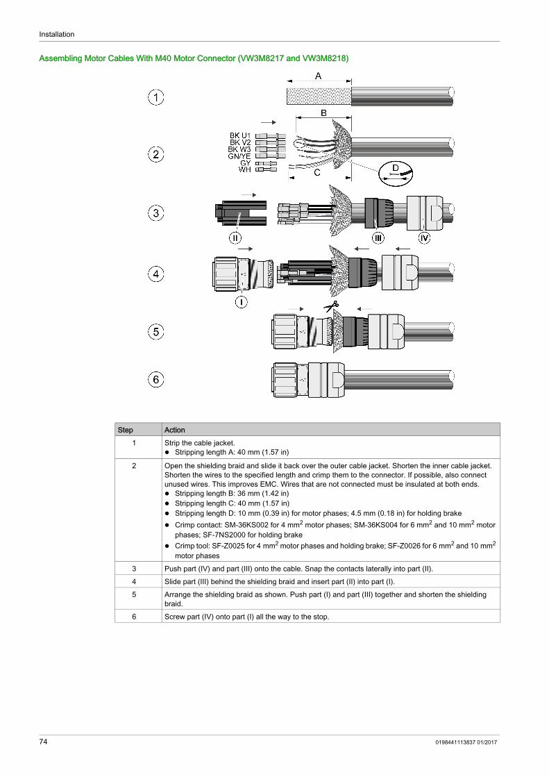
Installation
Assembling Motor Cables With M40 Motor Connector (VW3M8217 and VW3M8218)
Step Action1 Strip the cable jacket.
Stripping length A: 40 mm (1.57 in)
2 Open the shielding braid and slide it back over the outer cable jacket. Shorten the inner cable jacket. Shorten the wires to the specified length and crimp them to the connector. If possible, also connect unused wires. This improves EMC. Wires that are not connected must be insulated at both ends. Stripping length B: 36 mm (1.42 in) Stripping length C: 40 mm (1.57 in) Stripping length D: 10 mm (0.39 in) for motor phases; 4.5 mm (0.18 in) for holding brake Crimp contact: SM-36KS002 for 4 mm2 motor phases; SM-36KS004 for 6 mm2 and 10 mm2 motor
phases; SF-7NS2000 for holding brake Crimp tool: SF-Z0025 for 4 mm2 motor phases and holding brake; SF-Z0026 for 6 mm2 and 10 mm2
motor phases3 Push part (IV) and part (III) onto the cable. Snap the contacts laterally into part (II).4 Slide part (III) behind the shielding braid and insert part (II) into part (I).5 Arrange the shielding braid as shown. Push part (I) and part (III) together and shorten the shielding
braid.6 Screw part (IV) onto part (I) all the way to the stop.
74 0198441113837 01/2017

Installation
Assembling Encoder Cables With Y-TEC Encoder Connector (VW3M8220)Refer to the Assembly Instructions for series 615 of Intercontecwww.intercontec.com
Assembling Encoder Cables With M23 Encoder Connector (VW3M8214)
Step Action1 Strip the cable jacket.
Stripping length A: 28 mm (1.1 in)
2 Open the shielding braid and slide it back over the outer cable jacket. Shorten the inner cable jacket. Shorten the wires to the specified length (see table below) and crimp them to the connector. If possible, also connect unused wires. This improves EMC. Wires that are not connected must be insulated at both ends. Stripping length B: 28 mm (1.1 in) Stripping length C: 4.5 mm (0.18 in) Crimp contact: RC-12S2000 Crimp tool: RC-Z2514
3 Push part (VII) and part (VI) onto the cable. The cable entry contains rubber seals of various sizes for different cable diameters. Use rubber seals matching the diameter of the cable. Enclose the shield with part (IV). Snap the contacts into part (II). Open part (III) at the side and enclose part (II) as well as the rear part of the contacts with it. Slide part (II) into part (I).
4 Slide part (IV) behind the shielding braid. Slide part (VI) over part (I).5 Screw part (IV) onto part (I) all the way to the stop.
0198441113837 01/2017 75

Installation
Connecting the CablesIncorrect installation of the cable may damage the insulation. Broken conductors in the cable or improperly connected connectors may promote arcing within the cable.
Place the female connector of the motor cable onto the motor connector and tighten the union nut. Proceed in the same manner with the connection cable of the encoder system.Keep the connection cables from being twisted when tightening the union nut.
Connect the motor cable and the encoder cable to the drive according to the wiring diagram of the drive. Ground the shield to a large surface area. See the product manual of the drive for information on
connecting the shield.
DANGERELECTRIC SHOCK, ARC FLASH AND FIRE Disconnect all power before plugging in or unplugging the connectors. Verify correct pin assignment of the connectors according to the specifications in this chapter before
connecting the cables. Verify that the connectors are properly inserted and locked before applying power. Avoid forces or movements of the cable at the cable entries.Failure to follow these instructions will result in death or serious injury.
76 0198441113837 01/2017

Installation
Holding Brake Connection
Applying the holding brake while the motor is running will cause excessive wear and loss of the braking force.
See chapter Holding Brake (see page 51) for technical data on braking while the load moves.Releasing the holding brake can cause an unintended movement, for example, lowering of the load in the case of vertical axes.
If the voltage is incorrect, the holding brake cannot be released which causes wear. If the voltage is higher than the specified voltage, the holding brake may be re-applied. If the voltage polarity is incorrect, the holding brake cannot be released.
A motor with a holding brake requires a suitable holding brake controller which releases the brake when the power stage is enabled and locks the motor shaft when the power stage is disabled.
WARNINGLOSS OF BRAKING FORCE DUE TO WEAR OR HIGH TEMPERATURE Do not use the holding brake as a service brake. Do not exceed the maximum number of brake applications and the kinetic energy during braking of
moving loads.Failure to follow these instructions can result in death, serious injury, or equipment damage.
WARNINGUNINTENDED MOVEMENT Verify that there are no persons or obstacles in the zone of operation when performing a test of the
holding brake. Take appropriate measures to avoid damage caused by falling or lowering loads or other unintended
movements.Failure to follow these instructions can result in death, serious injury, or equipment damage.
WARNINGMISOPERATION OF THE HOLDING BRAKE CAUSED BY INCORRECT VOLTAGE Verify that the specified voltage is available at the holding brake connection. Use a properly rated voltage-sensing device for measuring.Failure to follow these instructions can result in death, serious injury, or equipment damage.
0198441113837 01/2017 77

Installation
78 0198441113837 01/2017

BSHCommissioning0198441113837 01/2017
Commissioning
Chapter 4Commissioning
Commissioning
Drive systems may perform unanticipated movements because of incorrect connection or other errors.
Drive systems may perform unintended movements if unapproved combinations of drive and motor are used. Even if motors are similar, different adjustment of the encoder system may be a source of hazards. Even if the connectors for motor connection and encoder connection match mechanically, this does not imply that the motor is approved for use.
See chapter Approved Drives (see page 22) for a list of approved drives.Rotating parts may cause injuries and may catch clothing or hair. Loose parts or parts that are out of balance may be ejected.
The metal surfaces of the product may exceed 70 °C (158 °F) during operation.
DANGERELECTRIC SHOCK OR UNINTENDED EQUIPMENT OPERATION Keep foreign objects (such as chips, screws or wire clippings) from getting into the product. Verify the correct seating of seals and cable entries in order to avoid contamination such as deposits
and humidity.Failure to follow these instructions will result in death or serious injury.
WARNINGUNINTENDED MOVEMENT Verify proper wiring. Only start the system if there are no persons or obstructions in the zone of operation. Perform the first test runs without coupled loads. Only touch the motor shaft or the mounted output components if all power has been disconnected.Failure to follow these instructions can result in death, serious injury, or equipment damage.
WARNINGUNINTENDED MOVEMENTOnly use approved combinations of drive and motor.Failure to follow these instructions can result in death, serious injury, or equipment damage.
WARNINGMOVING, UNGUARDED EQUIPMENTVerify that rotating parts cannot cause injuries or equipment damage.Failure to follow these instructions can result in death, serious injury, or equipment damage.
0198441113837 01/2017 79
Commissioning
Motors can generate strong local electrical and magnetic fields. This can cause interference in electromag-netically sensitive devices.
Prior to commissioning, verify correct installation.
NOTE: Observe the information on commissioning in the product manual of the drive.
WARNINGHOT SURFACES Avoid unprotected contact with hot surfaces. Do not allow flammable or heat-sensitive parts in the immediate vicinity of hot surfaces. Verify that the heat dissipation is sufficient by performing a test run under maximum load conditions.Failure to follow these instructions can result in death, serious injury, or equipment damage.
WARNINGELECTROMAGNETIC FIELDS Keep persons with electronic medical implants, such as pacemakers, away from the motor. Do not place electromagnetically sensitive devices in the vicinity of the motor.Failure to follow these instructions can result in death, serious injury, or equipment damage.
WARNINGIMPROPER APPLICATION OF FORCES Do not use the motor as a step to climb into or onto the machine. Do not use the motor as a load-bearing part. Use hazard labels and guards on your machine to help prevent the improper application of forces on
the motor.Failure to follow these instructions can result in death, serious injury, or equipment damage.
Step Action1 Verify proper mechanical installation.2 Verify proper electrical installation.
Did you connect all protective ground conductors? Did you properly connect and install all cables and connectors? Did you tighten the cable glands properly?
3 Verify that the ambient conditions are met. Does the installation meet the ambient conditions specified?
4 Verify the output components. Have the installed output components been balanced and accurately aligned?
5 Verify the parallel key at the shaft end of the motor. If you have a motor with a parallel key groove and parallel key, the parallel key must not be
inserted during commissioning without output component or it must be appropriately secured.6 Verify the function of the holding brake.
Is the holding brake able to hold the maximum load? Is the holding brake released prior to the start of a movement?
80 0198441113837 01/2017

BSHDiagnostics and Troubleshooting0198441113837 01/2017
Diagnostics and Troubleshooting
Chapter 5Diagnostics and Troubleshooting
What Is in This Chapter?This chapter contains the following topics:
Topic PageMechanical Issues 82Electrical Issues 82
0198441113837 01/2017 81

Diagnostics and Troubleshooting
Mechanical Issues
Electrical Issues
Issue Cause TroubleshootingExcessive heat Overload Reduce load
Holding brake not released Verify that the holding brake controller operates properly
Heavy pollution Clean the motorWhistling or knocking noise Rolling bearings Contact your sales officeGrinding noise Rotating output component grinds Align output componentRadial oscillation Poor alignment of output component Align output component
Output component out of balance Balance output componentShaft bent Contact your sales officeResonance with machine bed Suppress resonance
Axial oscillation Poor alignment of output component Align output componentDamage to the output component Repair/replace output componentResonance with machine bed Suppress resonance
Issue Cause SolutionMotor does not start or has difficulty starting
Overload Reduce load.Unsuitable settings for the drive Correct drive settings.Cable damaged Replace damaged cables.
Excessive heat Overload Reduce power.Heat at the terminals or connectors
Poor contact Tighten the terminals / connectors with the specified tightening torque.
82 0198441113837 01/2017

BSHAccessories and Spare Parts0198441113837 01/2017
Accessories and Spare Parts
Chapter 6Accessories and Spare Parts
What Is in This Chapter?This chapter contains the following topics:
Topic PageIP67 Kit 84Connectors 85Motor Cables 86Encoder Cables 89
0198441113837 01/2017 83

Accessories and Spare Parts
IP67 Kit
Degree of protection IP65 (shaft sealing ring) is a prerequisite for the use of the IP67 kit.Hardware version ≥RS02:
Hardware version <RS02:
Description ReferenceIP67 kit for size 055, cover with compressed air connection, O-ring, 4 screws VW3M2300IP67 kit for size 070, cover with compressed air connection, O-ring, 4 screws VW3M2301IP67 kit for size 100, cover with compressed air connection, O-ring, 4 screws VW3M2302IP67 kit for size 140, cover with compressed air connection, O-ring, 4 screws VW3M2303IP67 kit for size 205, cover with compressed air connection, O-ring, 4 screws VW3M2304
Description ReferenceIP67 kit for size 055, cover with compressed air connection, O-ring, 4 screws VW3M2305IP67 kit for size 070, cover with compressed air connection, O-ring, 4 screws VW3M2306IP67 kit for size 100, cover with compressed air connection, O-ring, 4 screws VW3M2307IP67 kit for size 140, cover with compressed air connection, O-ring, 4 screws VW3M2308IP67 kit for size 205, cover with compressed air connection, O-ring, 4 screws VW3M2304
84 0198441113837 01/2017

Accessories and Spare Parts
Connectors
The tools required for cable assembly can be ordered directly from the manufacturer. Crimping tool for power connector Y-TEC:
Intercontec C0.201.00 or C0.235.00www.intercontec.com
Crimping tool for power connector M23/M40:Coninvers SF-Z0025, SF-Z0026www.coninvers.com
Crimping tool for encoder connector Y-TEC:Intercontec C0.201.00 or C0.235.00www.intercontec.com
Crimping tool for encoder connector M23:Coninvers RC-Z2514www.coninvers.com
Crimping tools for encoder connector RJ45 10 pins:Yamaichi Y-ConTool-11, Y-ConTool-20, Y-ConTool-30www.yamaichi.com
Description Reference
Connector for motor cable, motor side Y-TEC, 1 mm2, 5 pcs VW3M8219
Connector for motor cable, motor side M23, 1.5 ... 2.5 mm2, 5 pcs VW3M8215
Connector for motor cable, motor side M40, 4 mm2, 5 pcs VW3M8217
Connector for motor cable, motor side M40, 6...10 mm2, 5 pcs VW3M8218
Connector for encoder cable, motor side Y-TEC, 5 pcs VW3M8220Connector for encoder cable, motor side M23, 5 pcs VW3M8214Connector for encoder cable, drive side RJ45 (10 pins), 5 pcs VW3M2208
0198441113837 01/2017 85

Accessories and Spare Parts
Motor Cables
Motor Cables 1.0 mm2
Motor Cables 1.5 mm2
Motor Cables 2.5 mm2
Description Reference
Motor cable 3 m (9.84 ft), (4 x 1.0 mm2 + 2 x (2 x 0.75 mm2)) shielded; motor end 8-pin circular connector Y-TEC, other cable end open
VW3M5100R30
Motor cable 5 m (16.4 ft), (4 x 1.0 mm2 + 2 x (2 x 0.75 mm2)) shielded; motor end 8-pin circular connector Y-TEC, other cable end open
VW3M5100R50
Motor cable 10 m (32.8 ft), (4 x 1.0 mm2 + 2 x (2 x 0.75 mm2)) shielded; motor end 8-pin circular connector Y-TEC, other cable end open
VW3M5100R100
Motor cable 15 m (49.2 ft), (4 x 1.0 mm2 + 2 x (2 x 0.75 mm2)) shielded; motor end 8-pin circular connector Y-TEC, other cable end open
VW3M5100R150
Motor cable 25 m (82 ft), (4 x 1.0 mm2 + 2 x (2 x 0.75 mm2)) shielded; motor end 8-pin circular connector Y-TEC, other cable end open
VW3M5100R250
Motor cable 100 m (328 ft), (4 x 1.0 mm2 + 2 x (2 x 0.75 mm2)) shielded; both cable ends open
VW3M5300R1000
Description Reference
Motor cable 1.5 m (4.92 ft), (4 x 1.5 mm2 + (2 x 1 mm2)) shielded; motor end 8-pin circular connector M23, other cable end open
VW3M5101R15
Motor cable 3 m (9.84 ft), (4 x 1.5 mm2 + (2 x 1 mm2)) shielded; motor end 8-pin circular connector M23, other cable end open
VW3M5101R30
Motor cable 5 m (16.4 ft), (4 x 1.5 mm2 + (2 x 1 mm2)) shielded; motor end 8-pin circular connector M23, other cable end open
VW3M5101R50
Motor cable 10 m (32.8 ft), (4 x 1.5 mm2 + (2 x 1 mm2)) shielded; motor end 8-pin circular connector M23, other cable end open
VW3M5101R100
Motor cable 15 m (49.2 ft), (4 x 1.5 mm2 + (2 x 1 mm2)) shielded; motor end 8-pin circular connector M23, other cable end open
VW3M5101R150
Motor cable 20 m (65.6 ft), (4 x 1.5 mm2 + (2 x 1 mm2)) shielded; motor end 8-pin circular connector M23, other cable end open
VW3M5101R200
Motor cable 25 m (82 ft), (4 x 1.5 mm2 + (2 x 1 mm2)) shielded; motor end 8-pin circular connector M23, other cable end open
VW3M5101R250
Motor cable 50 m (164 ft), (4 x 1.5 mm2 + (2 x 1 mm2)) shielded; motor end 8-pin circular connector M23, other cable end open
VW3M5101R500
Motor cable 75 m (246 ft), (4 x 1.5 mm2 + (2 x 1 mm2)) shielded; motor end 8-pin circular connector M23, other cable end open
VW3M5101R750
Motor cable 25 m (82 ft), (4 x 1.5 mm2 + (2 x 1 mm2)) shielded; both cable ends open VW3M5301R250
Motor cable 50 m (164 ft), (4 x 1.5 mm2 + (2 x 1 mm2)) shielded; both cable ends open VW3M5301R500
Motor cable 100 m (328 ft), (4 x 1.5 mm2 + (2 x 1 mm2)) shielded; both cable ends open VW3M5301R1000
Description Reference
Motor cable 3 m (9.84 ft), (4 x 2.5 mm2 + (2 x 1 mm2)) shielded; motor end 8-pin circular connector M23, other cable end open
VW3M5102R30
Motor cable 5 m (16.4 ft), (4 x 2.5 mm2 + (2 x 1 mm2)) shielded; motor end 8-pin circular connector M23, other cable end open
VW3M5102R50
Motor cable 10 m (32.8 ft), (4 x 2.5 mm2 + (2 x 1 mm2)) shielded; motor end 8-pin circular connector M23, other cable end open
VW3M5102R100
Motor cable 15 m (49.2 ft), (4 x 2.5 mm2 + (2 x 1 mm2)) shielded; motor end 8-pin circular connector M23, other cable end open
VW3M5102R150
86 0198441113837 01/2017

Accessories and Spare Parts
Motor Cables 4 mm2
Motor Cables 6 mm2
Motor cable 20 m (65.6 ft), (4 x 2.5 mm2 + (2 x 1 mm2)) shielded; motor end 8-pin circular connector M23, other cable end open
VW3M5102R200
Motor cable 25 m (82 ft), (4 x 2.5 mm2 + (2 x 1 mm2)) shielded; motor end 8-pin circular connector M23, other cable end open
VW3M5102R250
Motor cable 50 m (164 ft), (4 x 2.5 mm2 + (2 x 1 mm2)) shielded; motor end 8-pin circular connector M23, other cable end open
VW3M5102R500
Motor cable 75 m (246 ft), (4 x 2.5 mm2 + (2 x 1 mm2)) shielded; motor end 8-pin circular connector M23, other cable end open
VW3M5102R750
Motor cable 25 m (82 ft), (4 x 2.5 mm2 + (2 x 1 mm2)) shielded; both cable ends open VW3M5302R250
Motor cable 50 m (164 ft), (4 x 2.5 mm2 + (2 x 1 mm2)) shielded; both cable ends open VW3M5302R500
Motor cable 100 m (328 ft), (4 x 2.5 mm2 + (2 x 1 mm2)) shielded; both cable ends open VW3M5302R1000
Description Reference
Description Reference
Motor cable 3 m (9.84 ft), (4 x 4 mm2 + (2 x 1 mm2)) shielded; motor end 8-pin circular connector M40, other cable end open
VW3M5103R30
Motor cable 5 m (16.4 ft), (4 x 4 mm2 + (2 x 1 mm2)) shielded; motor end 8-pin circular connector M40, other cable end open
VW3M5103R50
Motor cable 10 m (32.8 ft), (4 x 4 mm2 + (2 x 1 mm2)) shielded; motor end 8-pin circular connector M40, other cable end open
VW3M5103R100
Motor cable 15 m (49.2 ft), (4 x 4 mm2 + (2 x 1 mm2)) shielded; motor end 8-pin circular connector M40, other cable end open
VW3M5103R150
Motor cable 20 m (65.6 ft), (4 x 4 mm2 + (2 x 1 mm2)) shielded; motor end 8-pin circular connector M40, other cable end open
VW3M5103R200
Motor cable 25 m (82 ft), (4 x 4 mm2 + (2 x 1 mm2)) shielded; motor end 8-pin circular connector M40, other cable end open
VW3M5103R250
Motor cable 50 m (164 ft), (4 x 4 mm2 + (2 x 1 mm2)) shielded; motor end 8-pin circular connector M40, other cable end open
VW3M5103R500
Motor cable 75 m (246 ft), (4 x 4 mm2 + (2 x 1 mm2)) shielded; motor end 8-pin circular connector M40, other cable end open
VW3M5103R750
Motor cable 25 m (82 ft), (4 x 4 mm2 + (2 x 1 mm2)) shielded; both cable ends open VW3M5303R250
Motor cable 50 m (164 ft), (4 x 4 mm2 + (2 x 1 mm2)) shielded; both cable ends open VW3M5303R500
Motor cable 100 m (328 ft), (4 x 4 mm2 + (2 x 1 mm2)) shielded; both cable ends open VW3M5303R1000
Description Reference
Motor cable 3 m (9.84 ft), (4 x 6 mm2 + (2 x 1 mm2)) shielded; motor end 8-pin circular connector M40, other cable end open
VW3M5105R30
Motor cable 5 m (16.4 ft), (4 x 6 mm2 + (2 x 1 mm2)) shielded; motor end 8-pin circular connector M40, other cable end open
VW3M5105R50
Motor cable 10 m (32.8 ft), (4 x 6 mm2 + (2 x 1 mm2)) shielded; motor end 8-pin circular connector M40, other cable end open
VW3M5105R100
Motor cable 15 m (49.2 ft), (4 x 6 mm2 + (2 x 1 mm2)) shielded; motor end 8-pin circular connector M40, other cable end open
VW3M5105R150
Motor cable 20 m (65.6 ft), (4 x 6 mm2 + (2 x 1 mm2)) shielded; motor end 8-pin circular connector M40, other cable end open
VW3M5105R200
Motor cable 25 m (82 ft), (4 x 6 mm2 + (2 x 1 mm2)) shielded; motor end 8-pin circular connector M40, other cable end open
VW3M5105R250
0198441113837 01/2017 87

Accessories and Spare Parts
Motor cable 50 m (164 ft), (4 x 6 mm2 + (2 x 1 mm2)) shielded; motor end 8-pin circular connector M40, other cable end open
VW3M5105R500
Motor cable 75 m (246 ft), (4 x 6 mm2 + (2 x 1 mm2)) shielded; motor end 8-pin circular connector M40, other cable end open
VW3M5105R750
Motor cable 25 m (82 ft), (4 x 6 mm2 + (2 x 1 mm2)) shielded; both cable ends open VW3M5305R250
Motor cable 50 m (164 ft), (4 x 6 mm2 + (2 x 1 mm2)) shielded; both cable ends open VW3M5305R500
Motor cable 100 m (328 ft), (4 x 6 mm2 + (2 x 1 mm2)) shielded; both cable ends open VW3M5305R1000
Description Reference
88 0198441113837 01/2017

Accessories and Spare Parts
Encoder Cables
Description Reference
Encoder cable 3 m (9.84 ft), (3 x 2 x 0.14 mm2 + 2 x 0.34 mm2) shielded; motor end 12-pin circular connector Y-TEC, device end 10-pin connector RJ45
VW3M8100R30
Encoder cable 5 m (16.4 ft), (3 x 2 x 0.14 mm2 + 2 x 0.34 mm2) shielded; motor end 12-pin circular connector Y-TEC, device end 10-pin connector RJ45
VW3M8100R50
Encoder cable 10 m (32.8 ft), (3 x 2 x 0.14 mm2 + 2 x 0.34 mm2) shielded; motor end 12-pin circular connector Y-TEC, device end 10-pin connector RJ45
VW3M8100R100
Encoder cable 15 m (49.2 ft), (3 x 2 x 0.14 mm2 + 2 x 0.34 mm2) shielded; motor end 12-pin circular connector Y-TEC, device end 10-pin connector RJ45
VW3M8100R150
Encoder cable 25 m (82 ft), (3 x 2 x 0.14 mm2 + 2 x 0.34 mm2) shielded; motor end 12-pin circular connector Y-TEC, device end 10-pin connector RJ45
VW3M8100R250
Encoder cable 1.5 m (4.92 ft), (3 x 2 x 0.14 mm2 + 2 x 0.34 mm2) shielded; motor end 12-pin circular connector M23, device end 10-pin connector RJ45
VW3M8102R15
Encoder cable 3 m (9.84 ft), (3 x 2 x 0.14 mm2 + 2 x 0.34 mm2) shielded; motor end 12-pin circular connector M23, device end 10-pin connector RJ45
VW3M8102R30
Encoder cable 5 m (16.4 ft), (3 x 2 x 0.14 mm2 + 2 x 0.34 mm2) shielded; motor end 12-pin circular connector M23, device end 10-pin connector RJ45
VW3M8102R50
Encoder cable 10 m (32.8 ft), (3 x 2 x 0.14 mm2 + 2 x 0.34 mm2) shielded; motor end 12-pin circular connector M23, device end 10-pin connector RJ45
VW3M8102R100
Encoder cable 15 m (49.2 ft), (3 x 2 x 0.14 mm2 + 2 x 0.34 mm2) shielded; motor end 12-pin circular connector M23, device end 10-pin connector RJ45
VW3M8102R150
Encoder cable 20 m (65.6 ft), (3 x 2 x 0.14 mm2 + 2 x 0.34 mm2) shielded; motor end 12-pin circular connector M23, device end 10-pin connector RJ45
VW3M8102R200
Encoder cable 25 m (82 ft), (3 x 2 x 0.14 mm2 + 2 x 0.34 mm2) shielded; motor end 12-pin circular connector M23, device end 10-pin connector RJ45
VW3M8102R250
Encoder cable 50 m (164 ft), (3 x 2 x 0.14 mm2 + 2 x 0.34 mm2) shielded; motor end 12-pin circular connector M23, device end 10-pin connector RJ45
VW3M8102R500
Encoder cable 75 m (246 ft), (3 x 2 x 0.14 mm2 + 2 x 0.34 mm2) shielded; motor end 12-pin circular connector M23, device end 10-pin connector RJ45
VW3M8102R750
Encoder cable 25 m (82 ft), (3 x 2 x 0.14 mm2 + 2 x 0.34 mm2) shielded; both cable ends open VW3M8222R250
Encoder cable 50 m (164 ft), (3 x 2 x 0.14 mm2 + 2 x 0.34 mm2) shielded; both cable ends open
VW3M8222R500
Encoder cable 100 m (328 ft), (3 x 2 x 0.14 mm2 + 2 x 0.34 mm2) shielded; both cable ends open
VW3M8222R1000
0198441113837 01/2017 89

Accessories and Spare Parts
90 0198441113837 01/2017

BSHService, Maintenance, and Disposal0198441113837 01/2017
Service, Maintenance, and Disposal
Chapter 7Service, Maintenance, and Disposal
What Is in This Chapter?This chapter contains the following topics:
Topic PageService Addresses 92Maintenance 92Replacing the Motor 94Shipping, Storage, Disposal 95
0198441113837 01/2017 91

Service, Maintenance, and Disposal
Service Addresses
Schneider Electric Automation GmbHSchneiderplatz 197828 Marktheidenfeld, GermanyPhone: +49 (0) 9391 / 606 - 0Fax: +49 (0) 9391 / 606 - 4000Email: [email protected]: http://www.schneider-electric.com
Machine Solutions ServiceSchneiderplatz 197828 Marktheidenfeld, GermanyPhone: +49 (0) 9391 / 606 - 3265Fax: +49 (0) 9391 / 606 - 3340Email: [email protected]: http://www.schneider-electric.com
Additional Contact AddressesSee the homepage for additional contact addresses:http://www.schneider-electric.com
Maintenance
Maintenance PlanThere are no user-serviceable parts within the motor.Either replace the complete motor, or contact Schneider Electric.The product may only be repaired by a Schneider Electric customer service center.
Use only the accessories and mounting parts specified in the documentation and no third-party devices or components that have not been expressly approved by Schneider Electric. Do not modify the equipment.Include the following points in the maintenance plan of your machine.
Connections and Fastening Inspect all connection cables and connectors regularly for damage. Replace damaged cables
immediately. Verify regularly that all output elements are firmly seated. Verify regularly that all mechanical and electrical threaded connections are tightened to the specified
torque.
Lubricating the Shaft Sealing RingIn the case of motors with shaft sealing ring, lubricant must be applied to the space between the sealing lip of the shaft sealing ring and the shaft with a suitable non-metallic tool. If the shaft sealing rings are allowed to run dry, the service life of the shaft sealing rings will be significantly reduced.
WARNINGUNINTENDED EQUIPMENT OPERATION Only use software and hardware components approved by Schneider Electric for use with this
equipment. Do not attempt to service this equipment outside of authorized Schneider Electric service centers. Update your application program every time you change the physical hardware configuration.Failure to follow these instructions can result in death, serious injury, or equipment damage.
92 0198441113837 01/2017

Service, Maintenance, and Disposal
CleaningIf the permissible environmental conditions are not respected, external substances from the environment may penetrate the product and cause unintended movement or equipment damage.
Clean dust and dirt off the product at regular intervals. Insufficient heat dissipation to the ambient air may excessively increase the temperature.Motors are not suitable for cleaning with a pressure washer. The high pressure may force water into the motor.Care must be taken with cleaning products as some active agents may have deleterious effects on plastics and welds. When using solvents or cleaning agents, verify that the cables, cable entry seals, O-rings and motor paint are not damaged.
Inspecting/Breaking In the Holding BrakeThe holding brake is broken-in at the factory. If the holding brake is not used for an extended period of time, parts of the holding brake may corrode. Corrosion reduces the holding torque.If the holding brake does not have the holding torque indicated in the technical data, it must be broken in again. If the motor is mounted, dismount the motor. Measure the holding torque of the holding brake using a torque wrench. If the holding torque of the holding brake considerably differs from the specified values, manually rotate
the motor shaft by 25 rotations in both directions. See chapter Holding Brake (see page 51) for the values.
Repeat the process up to 3 times, until you can restore the original holding torque.Contact your Schneider Electric sales office if the original holding torque is not restored.
Replacing the Rolling BearingWhen the rolling bearing is replaced, the motor is partially demagnetized and loses power.
For all service matters, contact your Schneider Electric representative.
WARNINGUNINTENDED MOVEMENT Verify that the environmental conditions are respected. Do not allow seals to run dry. Keep liquids from getting to the shaft bushing (for example, in mounting position IM V3). Do not expose the shaft sealing rings and cable entries of the motor to the direct spray of a pressure
washer.Failure to follow these instructions can result in death, serious injury, or equipment damage.
NOTICECORROSION CAUSED BY CLEANING AGENTS Before using a cleaning agent, carry out a compatibility test in relation to the cleaning agent and the
component affected. Do not use alkaline cleaning agents. Do not use cleaning agents containing chloride. Do not use cleaning agents containing sulfuric acid.Failure to follow these instructions can result in equipment damage.
NOTICEINOPERABLE EQUIPMENTDo not replace the rolling bearing.Failure to follow these instructions can result in equipment damage.
0198441113837 01/2017 93

Service, Maintenance, and Disposal
Replacing the Motor
If you replace the motor, the absolute position of the encoder is no longer valid.
WARNINGUNINTENDED MOVEMENT DUE TO INCORRECT ABSOLUTE POSITIONSet the new absolute position of the encoder after having replaced the motor.Failure to follow these instructions can result in death, serious injury, or equipment damage.
Step Action1 Power off all supply voltages. Verify that no voltages are present.2 Label all connections and uninstall the product.3 Note the identification number and the serial number shown on the product
nameplate for later identification.4 Install the new product as per chapter Installation (see page 53).5 Commission the product as per chapter Commissioning (see page 79).
94 0198441113837 01/2017

Service, Maintenance, and Disposal
Shipping, Storage, Disposal
ShippingThe product must be protected against shocks during transportation. If possible, use the original packaging for shipping.
StorageThe product may only be stored in spaces where the specified permissible ambient conditions are met.Protect the product from dust and dirt.
DisposalThe product consists of various materials that can be recycled. Dispose of the product in accordance with local regulations.Visit http://www.schneider-electric.com/green-premium for information and documents on environmental protection as per ISO 14025 such as: EoLi (Product End-of-Life Instructions) PEP (Product Environmental Profile)
0198441113837 01/2017 95

Service, Maintenance, and Disposal
96 0198441113837 01/2017

BSHGlossary0198441113837 01/2017
Glossary
AAxial forces
Tension or compression forces acting longitudinally on the shaft
CCentering collar
Centering device at the motor flange that allows for accurate motor mounting.
DDegree of protection
The degree of protection is a standardized specification for electrical equipment that describes the protection against the ingress of foreign objects and water (for example: IP 20).
DOMDate of manufacturing: The nameplate of the product shows the date of manufacture in the format DD.MM.YY or in the format DD.MM.YYYY. For example:31.12.11 corresponds to December 31, 201131.12.2011 corresponds to December 31, 2011
Drive systemSystem consisting of controller, drive and motor.
EEMC
Electromagnetic compatibility
LLength
In the type code, the length is defined in terms of the number of stacks.
PPELV
Protective Extra Low Voltage, low voltage with isolation. For more information: IEC 60364-4-41
RRadial forces
Forces that act radially on the shaft
SSize
In the type code, the size is defined in terms of the flange size.
0198441113837 01/2017 97

Glossary
98 0198441113837 01/2017
BSHIndex0198441113837 01/2017
Index
AApproved drives, 22
Ccable specifications, 60
Ddisposal, 95, 95
EEMC, 55
Motor cable and encoder cable, 55Encoder, 49Encoder cable
EMC requirements, 55Equipotential bonding conductors, 56
Fforce for pressing on, 34
Ggeneral characteristics, 18
Hholding brake, 51holding brake connection, 77
IInstallation, 53
Mmaintenance, 92Motor cable
EMC requirements, 55mounting position, 63
Nnameplate, 13
RReplacing the motor, 94
SSEK37 Singleturn, 50SEL37 Multiturn, 50service addresses, 92shaft load, 34shaft-specific data, 34
0198441113837 01/2017
shipping, 95SKM36 Multiturn, 49SKS36 Singleturn, 49storage, 95
Ttype code, 15
99

Index
100 0198441113837 01/2017