bsd - ewchile.com · a61z0_en_technical documentation_v1.1.doc 1/41 remote monitoring box technical...
TRANSCRIPT
A61Z0_en_Technical documentation_v11doc 141
REMOTE MONITORING BOX
TECHNICAL DOCUMENTATION
CRE Technology believes that all information provided herein is correct and reliable and reserves the right to update at any time CRE Technology does not assume any responsibility for its use E amp O E
CRE Technology 130 Alleacutee Charles-Victor Naudin
Zone des Templiers - Sophia Antipolis 06410 BIOT - FRANCE
Phone + 33 (0)492388682 - Fax + 33 (0)492388683 wwwcretechnologycom - infocretechnologycom
SARL au Capital de 300000 Euros - RCS Antibes 7488 625 000 15 NdegTVA FR54 488 625 583
BSD
A61Z0_en_Technical documentation_v11doc 241
Date Version Comments Author
October 13th 2009 10 Initial version JM
July 25th 2012 11 Digital input wiring information MM
You can download this documentation and the different documentation relating to the BSD BSD Plus on our web site httpwwwcretechnologycom
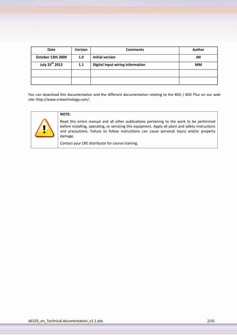
NOTE
Read this entire manual and all other publications pertaining to the work to be performed before installing operating or servicing this equipment Apply all plant and safety instructions and precautions Failure to follow instructions can cause personal injury andor property damage
Contact your CRE distributor for course training
A61Z0_en_Technical documentation_v11doc 341
Table of contents
1 About the BSD 6 11 General 6 12 Mounting 7 13 Bottom connectors 7 14 Top terminal block 9 15 LED Indicators 11
2 Getting started 12 21 Configure the BSD IP-address 12
3 Web-page overview 15 31 Browser requirements 15
4 Log in 15
5 User interface 16 51 Menu overview 16 52 Where to start 16 53 User levels 17 54 About 17
6 Setup 17 61 Users 17 62 Modbus 18 63 Modem 20 64 Regional 21 65 E-mail 22 66 SNMP 23 67 Web server 23 68 Ethernet (TCPIP network settings) 24 69 System 24
7 Configuration 27 71 Work flow 27 72 Template 27 73 Devices 28 74 Alarm 29 75 Log 31
8 Everyday use 33 81 View page 33 82 Devices 33 83 Alarm 33 84 Log 33
9 Appendices 35 91 APPENDIX A Specifications 35 92 APPENDIX B Internal registers 36 93 APPENDIX C SNMP 37 94 APPENDIX D NetBiternet 39
10 Company Information 41
A61Z0_en_Technical documentation_v11doc 441
List of illustrations Figure 1 Product features 6
Figure 2 Mounting 7
Figure 3 DSUB-9 RS-232 and Ethernet Interfaces 7
Figure 4 RS-232 connector 8
Figure 5 Power Supply Connection 9
Figure 6 Connecting AC power 9
Figure 7 LED Indicators 11
Figure 8 Connecting the BSD to a hub or switch 12
Figure 9 Connecting the BSD directly to a PC 13
Figure 10 BSD config utility 13
Figure 11 Changing IP settings 14
Figure 12 Log in 15
Figure 13 - Access to CRE Technology in Sophia Antipolis 41
List of tables
Table 1 Terminology 5
Table 2 RS-232 connector pin functions 8
Table 3 Terminal block pins 10
Table 4 LED Description 11
Table 7 Internet registers 37
A61Z0_en_Technical documentation_v11doc 541
Term Extract Description
TCPIP Transmission Control Protocol Internet Protocol
TCP (Transmission Control Protocol) is a set of rules used along with the Internet Protocol (IP) to send data in the form of message units between computers over the Internet
HTTP Hyper Text Transfer Protocol
HTTP is a set of rules for exchanging files (text graphic images sound video and other multimedia files) on the Web
DHCP Dynamic Host Configuration Protocol
DHCP is a standard protocol that automates the process of configuring network hosts by allowing hosts to obtain IP addresses and configuration parameters
Gateway A device that makes it possible to transfer data between networks of different kind eg ModbusRTU and ModbusTCP
Template Describes a Modbus slave device as a collection of groups and parameters
Device A Modbus slave unit that is connected to the BSD
Table 1 Terminology
This symbol indicates useful instructions on how to use the product
This symbol indicates important information about the product
A61Z0_en_Technical documentation_v11doc 641
1 About the BSD
11 General
The BSD module acts as a bridge from Modbus TCP to Modbus RTU making it possible for a Modbus TCP based controller to connect with Modbus RTU based devices The BSD will also handle alarm management data-logging as well as providing a web-based user interface for accessing data
Some BSD features
Graphical user interface that is easy to work with
Support for device templates to allow easy and flexible management of configurations
Advanced modem handling with support for GSMGPRS modems as well as analogue (PSTN) modems
Improved alarm handling now with alarm history and SNMP support
Language support
Support for sending log-files via email
Support for the NetBiternet portal
Auto detection of attached Modbus slave devices
BSD supports an RS-232 connection through a 9-pin DSUB or RS-485 (screw connection) It also supports 10100Mbps Ethernet through a standard Ethernet connector (RJ-45)
It can be configured via a user-friendly web-interface or by using the BSD Config utility (available at httpwwwcretechnologycom )
Figure 1 Product features
A61Z0_en_Technical documentation_v11doc 741
12 Mounting
A ndash Snap on B ndash Snap off
Figure 2 Mounting
Snap the BSD on to the DIN-rail (as described on picture A above)
13 Bottom connectors
Figure 3 DSUB-9 RS-232 and Ethernet Interfaces
131 Modbus RTU or Modem interface RS-232
The 9-pole DSUB male connector on the BSD module contains an RS-232 interface This port can be used to connect any equipment with an RS-232 interface
Serial interface (DSUB-9 RS-232)
Ethernet interface (RJ-45 10100Mbps)
A61Z0_en_Technical documentation_v11doc 841
Figure 4 RS-232 connector
Pin number Function
1 CD (Carrier Detect)
2 Rx (Receive)
3 Tx (Transmit)
4 DTR (Data Terminal Ready)
5 GND
6 DSR (Data Set Ready)
7 RTS (Request To Send)
8 CTS (Clear To Send)
9 RI (Ring Indicator)
Table 2 RS-232 connector pin functions
132 Ethernet interface
The Ethernet interface supports 10100Mbps using a standard RJ-45 connector
A61Z0_en_Technical documentation_v11doc 941
14 Top terminal block
Figure 5 Power Supply Connection
141 Power supply connection
The BSD can be powered by a 9-28VDC supply (Power requirement 2W)
The BSD with plastic housing can be powered by a 9-28VAC supply and should be connected as shown below
Figure 6 Connecting AC power
For versions with metal housing use only DC power supply
The following pins on the top terminal block are used for the power supply
Pin number Description
23 Vln ndash (Ground connection)
24 Vln +
A61Z0_en_Technical documentation_v11doc 1041
142 Digital inputs
The digital inputs are opto-isolated and are found at the top terminal block with the following pin numbers
Pin number Description
20 Digital input Common ndash Connect to 0VDC
21 Digital input 1+
22 Digital input 2+
The voltage levels for the logic states are
Logic state Voltage level (DC)
High 10hellip24 VDC - Digital inputs are activated when connected to positive DC supply (24VDC or 12VDC)
Low 0hellip2 VDC
143 RS-485 interface
The following pins on the top terminal block are used for the RS-485 interface
Pin number Description
13 RS-485 Line B
14 RS-485 Line A
15 Common
The RS-485 interface cannot be used at the same time as the terminal block interfaced RS-232
144 RS-232 Interface
The following pins on the top terminal block are used for the RS-232 interface
Pin number Description
15 Common
16 RS-232 Transmit (Output)
17 RS-232 Receive (Input)
Table 3 Terminal block pins
The RS-232 interface cannot be used at the same time as the RS-485 interface
A61Z0_en_Technical documentation_v11doc 1141
15 LED Indicators
Figure 7 LED Indicators
151 LED description
Name Colour Function
Module Status OFF No power
Green Module is running in normal mode
Orange During start-up
Serial link Status Flashing Green Serial Packet receive
Flashing Red Serial Packet transmit
Orange During start-up
Activitycollision Flashing Green Ethernet Packet receiving
Flashing Red Ethernet collision detected
Link OFF No Ethernet Link detected
Green Ethernet network detected 10Mbps
Orange Ethernet network detected 100Mbps
Table 4 LED Description
A61Z0_en_Technical documentation_v11doc 1241
2 Getting started
21 Configure the BSD IP-address
211 About the BSD Config utility
The BSD Config utility is a PC-based configuration utility to set TCPIP network settings in the BSD This utility has the ability to scan the Ethernet network for connected BSD devices and let the user set IP address net mask gateway DNS and hostname for each unit
212 Installation
System Requirements
Pentium 133 MHz or higher
5 Mb of free space on the hard drive
Windows 98MENT2000XPVista7
Network Interface Card (Ethernet)
Installation Procedure
Use the self-extracting installation package provided by CRE Technology and run it
213 Scanning for connected devices
First ensure that you have connected the BSD units you want to install on the same Ethernet network as the PC Use standard Ethernet cables straight-through or crossover cable depending on how you connect to the device See pictures below for details
Connecting the BSD to a hub or Switch
Figure 8 Connecting the BSD to a hub or switch
A61Z0_en_Technical documentation_v11doc 1341
Connecting the BSD directly to a PC
Figure 9 Connecting the BSD directly to a PC
When the BSD Config utility is started it will scan the Ethernet network for BSD devices All detected devices will be presented in a list in the main window If you want to force a new scan for devices you can press the ldquoScanrdquo button
Figure 10 BSD config utility
IP - The IP address of the BSD
SN - The subnet mask
GW - The default gateway
DHCP - Dynamically assigned IP address OnOff
Version - Firmware version
Type - Product type
MAC - The Ethernet MAC address
Use the ldquoAdvanced Optionsrdquo button to enable the BSD Config DHCP Server This is useful when you have set DHCP to ldquoOnrdquo in the BSD but donrsquot have a DHCP-server available on the network
A61Z0_en_Technical documentation_v11doc 1441
214 Changing IP settings
To change the IP settings on a detected device double-click on the device you want to configure in the list of devices This will open up a dialog where you can enter the desired IP configuration
To obtain the necessary information about IP address subnet mask etc please contact your network administrator
Figure 11 Changing IP settings
DO NOT SET DHCP TO ldquoONrdquo IF YOU DONrsquoT HAVE A DHCP-SERVER AVAILABLE ON THE NETWORK
Host Name - Here you can enter a hostname of your device (optional)
IP Address - The IP address of the BSD
Netmask - The subnet mask
Gateway - The default gateway
Primary DNS - The primary Domain Name Server (optional)
Secondary DNS - The secondary Domain Name Server (optional)
The default password for authentication of the new settings is ldquoadminrdquo
Pressing ldquoSetrdquo will cause the BSD device to reboot and after that the new settings will be enabled
You can test the new settings by opening a web-browser and entering the IP you assigned to the device If you selected DHCP and want to know what IP your device have been assigned you can do a new scan with the BSD Config utility to view the new network configuration
If the IP address is not available on your network please connect you PC directly to the BSD+ or contact supportcretechnologycom
A61Z0_en_Technical documentation_v11doc 1541
3 Web-page overview
31 Browser requirements
The web-pages are optimized for Internet Explorer version 6 or later and Mozilla Firefox version 2 or later Other browsers can work as well but the web-pages might appear differently and functionalities may be limited The browser must be JAVA enabled to use pages with JAVA content (like the graph page) If it is not please visit wwwjavacom to download a JAVA plug-in for your browser
4 Log in Open a web browser (Internet Explorer for example) and enter the IP address you have set on the BSD unit with the BSD Config utility For example if you entered the address 10101035 then you should enter the text below in the address field of the browser and press enter
http10101035
Now you should see the login screen
Figure 12 Log in
To be able to configure the Gateway you should enter ldquoadminrdquo in the user-name box The default password is ldquoadminrdquo
Later you can change the default password to something else (recommended)
This will be described in section 61
If you have problems to log in and you are sure that your password is correct make sure that ldquoCaps Lockrdquo is not enabled on your keyboard
A61Z0_en_Technical documentation_v11doc 1641
5 User interface
51 Menu overview
The menu items have a layout to help users get the most out of the BSD module The main menu has two workflow directions one for setting up the BSD module (from right to left) and one for using it as a SCADA interface (from left to right) When referring to a sub menu this document will use ie when referring to the sub menu Users which is found under Setup the following syntax will be used SetupUsers
Depending on the user level the menu items will be different see section 53
52 Where to start
521 Hardware and user setup
How to setup communication interfaces and users see section 6
522 Present data and send logsalarms
How to setup user interface for presenting data and configure alarms and logs see section 7
523 Everyday use
How to monitor data alarms and logs see section 8
A61Z0_en_Technical documentation_v11doc 1741
53 User levels
The menu items are accessible depending to the current userrsquos user level The user level is set for each user that is setup for the BSD module
User level Menu items showing typical use
Read Status Devices Alarm Log About used for users who need to monitor data
Write As for Read Used for users who should be able to acknowledge alarms clear logs alarm history
Admin As for Write + configuration Used for users that can alter the configuration add and change templates devices pages alarms log and bindings
Super admin As for Admin + Setup Used for users that set up communication interfaces such as modbus modem email server SNMP Ethernet and NetBiternet Can do backup and update firmware and install patches
54 About
This menu item shows a window with information about the firmware revision and MAC address for the BSD module More detailed information can be found under SetupFirmware see section 69
6 Setup The setup menu item is used to setup hardware interfaces and communications as well as users webserver and NetBiternet All basic settings to get the BSD module run with attached devices
Workflow for the sub menu is from left to right
61 Users
At this sub menu item users can be added to the system Users available can receive e-mail SMS depending on the configuration for the user To Edit a users option click on the users name and click save when ready
Only the Super Admin level has access to add and edit users
A61Z0_en_Technical documentation_v11doc 1841
Option Description
User-ID The userrsquos login name
Name Full name of the user
E-mail E-mail address for the user
Mobile Mobile phone number Is used to be able to send SMS to the user if SMS is enabled and the correct Alarm Class is set see section 755
Alarm Class When adding an alarm it is given an Alarm Class If the user should get the alarm the alarmrsquos corresponding Alarm Class has to be marked A user can have several alarm classes see section 755
Receive log files via E-mail If this option is enabled the user will get the log as an e-mail attachment if it is enabled at the log configuration see section 761
Language Select the user interface language There could be different languages set for different users
Show Device browser in menu Every parameter in of the templates uploaded to BSD can be viewed using the main menu option Devices If the user with user level admin
or write can change parameters and read on see parameters
User level The menu items are accessible depending on the current userrsquos user level see section 53 for more information
Password Userrsquos password Only has to be given when adding a new user or when changing the password which is done by checking the box Change password
Repeat Password When adding a user the password has to be repeated as well as when changing it
62 Modbus
Modbus - The default password for authentication of the new settings is admin
621 Modbus RTUModbus ASCII settings
This sub menu item lets the user configure the Modbus communication interface Make sure that the wiring is correct
The status page gives information about the Modbus connection and can be useful as a trouble shooting tool when setting up the Modbus interface See section 82
Option Description
Transmission mode
Set Modbus RTU or Modbus ASCII transmission mode [Default RTU]
Slave Response Timeout The time that the BSD module will wait for a response from a slave before Serial Timeout will occur [Default 1000] Serial Timeout can be monitored at the Status page see section 82
Physical interface Electrical interface that is used Make sure that the wiring is correct and connected to the interface
RS-485 see 143
RS-232 see 144
A61Z0_en_Technical documentation_v11doc 1941
RS-232 (D-Sub) see 131 [Default RS-485]
Baudrate Baud rate settings Can be 300-115 200 bps [Default 9600]
Character Format Parity Parity settings no even or odd parity [Default None]
Character format Stop Bit Number of stop bits 1or 2 stop bits (Default 1)
Extra delay between
messages
Time to delay between Modbus messages in milliseconds (Default 0)
Character delimiter
Number of milliseconds between characters in a Modbus frame Set to 0 to use Modbus standard 35 characters [Default 0]
Use function code 15
when writing single
bits(coils)
If this option is Enabled all writes to coils will be done with function code 15 (Useful if slaves do not support function code 05)
Use function code 16
when writing single
registers
If this option is Enabled all writes to registers will be done with function code 16 (Useful if slaves do not support function code 06)
622 Modbus TCP
Option Description
Port number The port to use for Modbus TCP communication [Default 502]
Gateway Registers If enabled the internal registers will be available at the slave address given in the Address-field The internal registers are specified in appendix B Some of the registers can be used for pages alarms and logs using the Internal Register as device The queries sent to this Modbus address will not be sent to the Modbus RTU network BSD module will respond to these queries by itself
Server Idle Timeout If enabled the idle timeout in seconds for the Modbus TCP connection can be set If there is no response within this time the connection will be closed If disabled the connection will not timeout [Default Enabled 60]
IP Authentication If enabled this feature makes it possible to configure the IP address that is allowed to connect to the gate way
There cannot be two devices with the same Modbus address If that is the case the serial bus will not be able to communicate with all slaves present on the bus
A61Z0_en_Technical documentation_v11doc 2041
63 Modem
On this page the modem setup is done An external modem which is optional can be either a GSMGPRS or an analogue modem (PSTN) that is attached to the RS-232 9-pin DSUB interface see 131
On the status page the current status of the modem is displayed see section 82
631 Modem settings
Option Description
Modem type Type of modem
Baudrate Baudrate used for the modem
Pin code If SIM card has PIN code security activated the pin code should be entered here followed by clicking test pin code to save the PIN code
Modem info A window with information about the connected modem will show If GSMGPRS it will give information about Manufacturer IMEI-number PIN status and signal strength There is information about the SIM code which could be ready if OK or SIMPIN or SIMPUK when demanding user action The PIN or PUK code is entered at Pin code when necessary The SIM card has to be registered on a network to be able to work which status can viewed on the line Network status
Test SMS If a GSMGPRS modem is attached enter a phone number to generate a test SMS to that number
632 Dial upGPRS setting
Settings used for BSD module to communicate with Internet using a modem Is used to send e-mail logs and alarms where there is no Ethernet connection available If NetBiternet is enabled and no Ethernet connection is available the Connection trigger has to be set to Always connected
Option Description
Connexion trigger Defines how the BSD module should connect to Internet When set to AlarmEvent it will make a connection when needed to send e-mail alarm log or other information that requires an Internet connection
Host to ping An address to a host IP address or server name to send a ping packet which will keep the connection to Internet This is used as a keep alive message
Ping timer Sets the interval for the keep-alive message Should be as long as possible to avoid unnecessary GPRS data traffic
Access Point Name
(APN) GPRS gateway that is given by the SIM card operator
Phone number Phone number to dial to the Internet Service Provider ISP
User name User name assigned by the ISP
Password Password assigned by the ISP
633 Dial-in settings
This section handles a dial in connection ie when the user should be able to call the BSD module using a modem
A network connection has to be set up on a PC where the phone number is the number of the SIM card used in the BSD module User name and password for the network connection should be those entered in this section
A61Z0_en_Technical documentation_v11doc 2141
Option Description
Local IP address The IP address assigned to the BSD module This IP number should be entered in the web browser after a connection is established
Remote IP address The IP address that will be assigned to the calling computer the remote client Must be the same sub net as Local IP number
User name User name used to establish a connection Is required on the PC when creating a network connection
Password Password used to establish a connection Is required on the PC when creating a network connection
64 Regional
The Regional page contains configuration for time and date generic module information and also configuration for how the log file list separator and decimal symbol should be represented
641 Time and date
Option Description
Date Current date Stored to a clock that will be battery backup up for maximum a week
Time Current time Enter the actual time Daylight saving and time zone are set separately Stored to a clock that will be battery backup up for maximum a week
Time zone The time zone that is used For time zones marked with daylight saving will be used Then time entered should be actual current time The BSD module will change time automatically
Network time
protocol Network time protocol NTP is a server from where data can be read and used to set time and date Requires an Internet connection
NTP server A server that support and can deliver NTP information Could be an IP address or domain name
Update interval Interval of how often the time and date should be synchronized with data from the server When using GSMGPRS the amount of data for every synchronization should be considered
642 Decimal separator
Option Description
Decimal separator and log
file value separator Sets the decimal separator and the separator character used for the csv-logfile [Default Dot () and Comma()]
643 Module information
Option Description
Site name A name for this BSD module that is used when sending test SMS and test e-mail to identify which module that sent the message The site name is shown left to the log out button in the user interface header
More information Notes for this BSD module This information will be shown here only
A61Z0_en_Technical documentation_v11doc 2241
65 E-mail
Option Description
SMTP server Server that is used for sending e-mail Could be entered as IP address or domain name
Port number This is an SMTP server setting and should be given by the Internet Service Provider ISP The port number is set to 25 by default for custom server When using NetBiternet services it is set to 2525 [default 25]
SMTP Authentication If the server requires a login the type of method it set here [default disabled]
User name User name for the SMTP server
Password Password for the SMTP server
Sender This is what will be shown in the FROM field of a the mail sent from the BSD module
Reply path The reply e-mail address
Send test E-mail This feature is used to test the SMTP settings Enter an e-mail address and click send A test mail will be sent to the address Some e-mail servers may consider this test mail as lsquojunkrsquo
A61Z0_en_Technical documentation_v11doc 2341
66 SNMP
More information about sending SNMP trap functionality see appendix C
Option Description
SNMP manager IP address or name of the SNMP manager which should receive SNMP traps
Port Port number that the SNMP manager will listen to (to detect SNMP traps)
If domain name is used make sure that the DNS setting for the Ethernet connection is correct
67 Web server
The web server settings refer to the internal web server of the BSD
Option Description
Extra web server port To connect to the Extra web server port the URL should have a colon followed by the new port number ie http101010308080 where 10101030 is the IP number or DNS address to the BSD module and
8080 the new port
Compression on web pages This feature is only used for the extra web server port
When set to enable the BSD module check if the browser support compressed pages and if that is the case it will send compressed pages
This feature will increase the workload of the BSD module why it is not enabled as default
There is an option to disable compression and the pages will be sent as
normal web pages which always is the case for the standard web server port 80
If it is set to force web pages will always send compressed regardless the support of the web browser
The information that a web-browser supports compressed data could sometimes be removed when passing some firewall or proxy servers This is true for the default setting for port 80 in Microsoft ISA servers To ensure that compressed web pages are sent anyway the option force should be set
Most web-browsers support compressed data
Auto update value and
status This feature is only used for the extra webserver port
To limit the amount of data transferred and increase speed when using low bandwith ie modem connection the data and values could be set to be updated by clicking the refresh button only This button will show at the upper right corner of the user interface
Automatic logout time Defines the time for how long a user can be inactive before the user is logged out due to session time out
If domain name is used make sure that the DNS setting for the Ethernet connection is correct
The web server will always listen to port 80 When using modem connection compression on web pages will always be enabled and Auto update will always be disabled to improve response time and the refresh button has to be clicked to update values and status
A61Z0_en_Technical documentation_v11doc 2441
68 Ethernet (TCPIP network settings)
The settings are the same as configured with BSD Config utility
Option Description
DHCP If enabled the BSD module will be assigned an IP address from the DHCP server on the net if there is one See note below
Host name A host name for the BSD module
IP Address IP address for BSD module
Subnet mask A subnet mask which should be identical to the subnet of the network
Gateway Network gateway
Primary DNS Domain name server to be able to access servers by domain
Secondary DNS Domain name server to be able to access servers by domain
Do not select the DHCP option unless you have a DHCP server available on the network
69 System
691 Backup settings
Option Description
Backup Settings To Local
Hard Drive All configurations except Ethernet settings will be backed up A file with the extensions nbb short for NetBiter Backup will be created that can be saved on the local hard drive
Restore module from
backup A file of nbb NetBiter Backup file can be used to restore the setup and configuration for the BSD module
A61Z0_en_Technical documentation_v11doc 2541
692 Firmware
This information is helpful when contacting CRE Support
Option Description
Select an update file This is used to update firmware files with extension nbu or install patch files with extension nbp for the BSD module
Make sure to make a backup before starting to update the firmware Latest firmware can be found on the CRE website When clicking update the BSD module will start updating Sometimes the web browser will not be able to display web pages Just wait for some minutes and try to view the page again The communication configuration for Ethernet modem and NetBiternet will not be affected which makes it possible to update firmware remotely
MAC address MAC address of the BSD module Ethernet interface
Kernel version Kernel version used in the BSD module
Application version Application version of the BSD module
Patches If there are patches installed in the system they will be displayed here with version and information about the patch
The latest firmware and kernel version can be found on the CRE Technology website
693 Tools
Option Description
Get all log files Put all log files and system information in a tar-archive
Restart module By clicking the reboot button the module will restart
Reset To Factory Default
Setting By clicking this button the BSD module will remove all settings and configurations and has to be setup and configured as a brand new BSD module
BSD with patches installed should be set to factory default using NetBiter Update to upload firmware
A61Z0_en_Technical documentation_v11doc 2641
694 NetBiternet
NetBiternet is a solution for remote management of NetBiter devices The BSD is preconfigured to be able to use these services
More information about the NetBiternet remote management service can be found at httpwwwnetbiternet
Option Description
NetBiternet service Enables the NetBiternet remote management services
Device ID This is the BSD device ID
Activation code Code to activate the BSD as valid device at NetBiternet The code entered by default
Send Alarms Enable alarms to be sent to NetBiternet
Send log files Enable log files to be sent to NetBiternet
When NetBiternet is enabled the SMTP server will automatically be set to NetBiternet with correct user name and password The NetBiternet services uses port 5222 for communication to the server
A61Z0_en_Technical documentation_v11doc 2741
7 Configuration The configuration menu item is used to configure the BSD module to display data and log data as well as send alarm messages
Before any data can be read from a Modbus device and be used for presenting alarms and logs the communication interface has to be setup see section 63
71 Work flow
Every Modbus device must have a Template Every Modbus device has to be configured as a Device with a Modbus address The device has to be assigned to a template When a Modbus device has been configured it can be used for data presentation alarms and logs
72 Template
A template describes what registers can be used and what type the register is It also contains information about how presentation should be shown such as scaling enumeration and readwrite access for the user interface
There are ready to use templates for Modbus devices that can be requested to supportcretechnologycom
721 Add upload and edit template
To administrate templates there are some buttons for this in the user interface
Button Edit template
Edit Edit template
Restore Used the over write a template with a template file that is uploaded
Backup To download a template file that could be locally stored and uploaded to restore or add a template
Delete Remove a template from the BSD module
Upload template Upload a template file and add it as a new device template
Add template Adds a new empty template that has to be configured which is done by clicking Edit after the template has been assigned a name
722 Edit
A template is structured into groups of parameter to gain simplicity when building pages adding alarms and logs
A parameter is a Modbus register with information about presentation type etc Several parameters can be grouped into one group
A template can be renamed using the button rename at the same row as the current template name
723 Template ndash Group
To add a new group click add group There has to be at least one group in a template The group can be renamed by clicking rename and erased by clicking delete
A61Z0_en_Technical documentation_v11doc 2841
724 Parameters
When adding a new parameter by clicking Add parameter an Edit parameter window will be open
For more detailed information click the question mark at upper right corner of the Edit parameter window
Option Description
Name The name of the parameter
Type Modbus register type
Address Modbus register address
Datatype Type of the data read If it is signed byte length and order
Scaling Scale the register value
Offset Offset the register value
Mask Mask a register value
Presentation The register value can be shown as read only readwrite and write only
Enumeration Values can be enumerated ie 0=off1=on to show values as text
Number of decimals Number of decimals that should be shown
Valid range Use to prevent user from writing a value outside a valid range
73 Devices
Every Modbus slave that is connected has to be added with a unique Modbus address Every device has to be assigned a device template
Autodetect can be used to add devices Every Modbus address will be scanned with the Modbus communication interface settings Every Modbus device connected has to have a unique address set before starting the auto detection The scanning will scan one Modbus address after another which could take some time to perform The scanning will be displayed in the progress bar
If the templates uploaded support identification for Modbus devices the correct template will be assigned If not the devices will be added and the user has to be assigned a template manually
By clicking add device the device can be manually setup
A61Z0_en_Technical documentation_v11doc 2941
731 Addedit device settings
Option Description
Name The name of the device
Template The template that should be used for this device
ModbusTCP server IP address The IP address for the ModbusTCP server If it is a ModbusRTU device It should be left blank
ModbusTCP server port The port to connect to the ModbusTCP server Modbus default is 502 [Default 502]
Modbus slave address The unique Modbus Address
732 Device specific alarms
If a template supports device specific alarms preconfigured alarms can be added The alarm condition is set in the template and cannot be changed The set button is used to set all alarms for the complete alarm list or an alarm group The set a single alarm the check box can be used The clear button is used to clear all alarms for the device specific alarm list or for an alarm group
The drop down box to set alarm class can be used to set the same class for a group or different alarm class for a single alarm see section 755 on page 28 for more information about Alarm class
74 Alarm
741 Alarm settings
Option Description
SMS Alarm Enable SMS alarm if a modem is configured see section 63
Users with correct alarm class and a mobile phone number will receive a SMS see section 61
Email Alarm Enable e-mail alarm if an SMTP server is configured see section 65
Users with correct alarm class and an e-mail address will receive an e-mail see section 61
SNMP Alarm Enable SNMP trap alarms if a SNMP manager is configured see section 66
Manual alarm
acknowledge If disabled all alarms have to be acknowledge When an alarm condition is fulfilled it sends an alarm message After the condition has been back to normal and is fulfilled again a new alarm message will be sent
If enabled the user has to acknowledge the alarm before a new alarm message is sent
Alarms can be acknowledged from NetBiternet user interface if these services are enabled see section 69
A61Z0_en_Technical documentation_v11doc 3041
742 Alarm configuration
The alarm configuration section contains a list of all configured alarm parameters The alarms can be reconfigured by clicking edit and the alarm parameter page with all options will be displayed The delete button will remove the alarm parameter To create a new alarm parameter click add alarm parameter There can be a maximum of 64 alarm parameters configured
743 Parameter set
Option Description
Device Select the device that has the parameter to be used for the alarm
Group Select the group that contains the parameter
Parameter Select the parameter that will be used for the alarm be presented
744 Alarm trigger operation
Option Description
Trig on The trig condition can be set as For values
Greater than
Less than
Equal to
Not equal to
Change
For Bit operations
Any
Neither
All
For the device
No response
Where the value is number of consecutive time outs
ValueBit Select if the value or bit representation field should be used to enter condition If scaling is set in the template the value will be compared to the scaled value
Value Enter a decimal value
Bit presentation Use the checkbox to mark what bit that should be used Marked checkbox represent a bit=1
A61Z0_en_Technical documentation_v11doc 3141
745 Alarm properties
Option Description
Alarm Class The alarm class is used to sort which alarm to send to which user The user can have one or more alarm class configured If an alarm will be trigged an alarm message will be sent to all user that has the alarm class configured
Severity The alarmrsquos severity Used to describe how critical the alarm is For SNMP there is a severity class called Clear which will be sent for an alarm that enters normal alarm condition
Description Text that is displayed in the alarm list view and alarm history and is sent to the SNMP manager
Subject The subject for alarm message sent by e-mail andor SMS
Message The message body of the alarm message sent by e-mail andor SMS The message length is limited to 70 characters for a SMS why it could be a good practice to keep it to that length
75 Log
The log can have 64 log parameters configured and will save samples to a CSV file This file can be viewed in the built in trend graph page or downloaded to be analyzed in eg Microsoft Excel or OpenOffice Calc
See section 84 for more information concerning CSV files (viewDownload)
751 Log configuration
Option Description
Estimated log time Gives estimation about the time before the log file is full This is an estimation and will depend on the configuration ie number of pages and parameters configured The number and size of pictures for the pages will also affect the log file size If the log interval is set to a predefined time this will show as the estimated log time
Log interval Defines the time interval for between the samples that is saved to the log file
Log type The log could be circular which will fill the log with data When full it can be sent A new file will be created and the old one is deleted
Maximum send log
interval This will set the time when a log should be sent If a time period is selected the log will be sent with this interval eg at the same minute for every hour when At least every hour is chosen The minute is different for each BSD module to spread load of Ethernet traffic and server load
Send log files as
E-mail attachment If a Send log interval is specified the log file is sent as an e-mail attachment to user that has configured this option see section 61
A61Z0_en_Technical documentation_v11doc 3241
752 Log parameters
The Log parameter section contains a list of all configured log parameters The log parameter can be reconfigured by clicking edit and the Edit log entry page with all options will be displayed
The delete button will remove the log parameter To create a new alarm parameter click add log parameter
There can be a maximum of 64 log parameters configured
753 Log ndash Edit log parameters
Option Description
Device Select the device that has the parameter that will be logged
Group Select the group that contains the parameter
Parameter Select the parameter that will be logged
Delta logging Stores the difference between the two last samples As an example a pulse counter is used This counter increase the value for each received pulse For delta logging this will result in
Counter Logged value
5 5
20 15
32 12
Description Description that is used on the trend graph page see section 851 and in the csv-file that can be downloaded
754 Bindings
With bindings a Modbus register can be copied to another
755 Bindings ndash Add data binding
Option Description
Source Device Select the device that has the parameter that will be copied
Source Group Select the group that contains the parameter
Source Parameter Select the parameter that will be copied
Destination Device Select the device that has the parameter that will be copied to
Destination Group Select the group that contains the parameter
Destination Parameter Select the parameter that will be copied to
Copy interval The interval for each copy
A61Z0_en_Technical documentation_v11doc 3341
8 Everyday use When a BSD module has been setup and configured it is ready for everyday use to monitor data send logs and alarms
81 View page
To view a page that has been configured use the dropdown box at the upper left corner of the user interface select the page to display
82 Devices
The Devices menu item is a browser that can browse all parameter in a template for a device and show current values
The page will show a list of all available Modbus devices A tree with all groups will show when expanding the tree Open a group by clicking on the group name to see values for each parameter
The Internal Registers will also be available to browse
83 Alarm
The alarm menu item keeps track of the alarm parameter configured and is used to see current state of all alarms as well as an alarm history where the alarm parameter condition changes can be monitored and if alarm message has been sent correctly
831 Alarm status
This is a list of all alarms The status of the alarm can be Ok or Present If the acknowledge is required the Acknowledge button will be active for alarms where the condition has been fulfilled If all the alarm that have been present and need to be acknowledge at the same time click the button Acknowledge all at the bottom of the list The lists default view is to show all present and not acknowledged alarms To view all alarms click Show all
To show only present alarm again click Show active
832 Alarm history
Every change for an alarm parameter is logged in Alarm history with information of the value for the parameter that trigged the alarm and information about messages sent from the BSD module There can be 100 entries in the alarm history list If the list is full and a new alarm occurs the oldest alarm history entry will be deleted If the Show
occurrence button is clicked only the entries with type Occurred will show which could be useful when analyzing alarms The Clear History button will clear all alarm history
84 Log
The log menu item is used for analyzing logged parameters The log could be viewed in a trend graph and be downloaded as a CSV file
841 View trend graph
This feature requires that the user has JAVA Virtual Machine installed By using a left click on the mouse keep the button down and release it at the diagonal corner of a box the graph will zoom to that size By right clicking and keeping the button down the graph can be moved by moving the mouse
A61Z0_en_Technical documentation_v11doc 3441
The first three (3) parameters will automatically be displayed in the graph by default Parameters can be shown or hidden by clicking the box in front of the parameter name When a parameter is shown the line color will have the same color as the box To hide a line click the box and it will be grey
842 Log
Option Description
Download Log To
Local Hard Drive Download the log from the BSD module to a local computer as a CSV file that can be analyzed in software like Microsoft Excel or OpenOffice Calc
The CSV delimiter character can be set in the Regional page see section 64
Clear Log File Will delete the log from the BSD module
Button Description
Scroll graph up
Scroll graph down
Scroll graph right
Scroll graph left
Reset view view all
Zoom in
Zoom out
A61Z0_en_Technical documentation_v11doc 3541
9 Appendices
91 APPENDIX A Specifications
Ethernet connection
10Base-T or 100Base-TX (IEEE 8023) RJ45 connector
Serial interface
RS-232 with full modem control (RTS CTS DCD DTR DSR RI)
300-115200bps
9-pin DSUB connector
RS-485
300-115200bps
screw connector
Power Supply
Plastic housing
9hellip28VAC (2W)
9hellip28VDC (2W)
Metal housing
9hellip28VDC (2W)
Temperature range
Operating -40 hellip 85degC
Storage -40 hellip 85degC
Humidity range
5-93 RH non-condensing
Cover material for plastic housing
LEXAN 940 self-extinguishing acc to UL94-V0
Mounting option
Plastic housing DIN rail (EN 50022) Metal housing Screw mounting (DIN rail optional)
CE certification
According to EN 61000-6-22005 and EN 61000-6-42001
A61Z0_en_Technical documentation_v11doc 3641
92 APPENDIX B Internal registers
Holding register
Name Values Options Comment
1 Digital input 1 status 0 or 1 Read only
2 Digital input 2 status 0 or 1 Read only
3 Number Active Connections MBTCP
0-10 Read only
4 Number Active Internal Connections
0-10 Read only
Serial Status (ModbusTCP) See section (33)
5 Valid responses 0-65535 Can be cleared
6 Serial timeouts 0-65535 Can be cleared
7 CRC errors 0-65535 Can be cleared
8 Input Buffer overruns 0-65535 Can be cleared
9 Frame errors 0-65535 Can be cleared
10 Exception responses 0-65535 Can be cleared
Serial Status (Buffered messages)
11 Valid responses 0-65535 Can be cleared
12 Serial timeouts 0-65535 Can be cleared
13 CRC errors 0-65535 Can be cleared
14 Input Buffer overruns 0-65535 Can be cleared
15 Frame errors 0-65535 Can be cleared
16 Exception responses 0-65535 Can be cleared
Serial Status (Internal requests and Webpages)
17 Valid responses 0-65535 Can be cleared
18 Serial timeouts 0-65535 Can be cleared
19 CRC errors 0-65535 Can be cleared
20 Input Buffer overruns 0-65535 Can be cleared
21 Frame errors 0-65535 Can be cleared
22 Exception responses 0-65535 Can be cleared
Configuration Registers
23 ModbusTCP Port 1-65535 Default port number is 502
24 Gateway Modbus address (-1)-255
-1 Disabled Default
0 - 255 Enabled
25 ModbusTCP idle timeout 0-65535 (seconds) Default 60 seconds
0 Disabled
A61Z0_en_Technical documentation_v11doc 3741
Holding register
Name Values Options Comment
1 - 65525 Enabled
26 Baudrate
2400 2400 bps
4800 4800 bps
9600 9600 bps Default value
19200 19200 bps
38400 38400 bps
57600 57600 bps
115200 115200 bps
27 Parity 0-2
0 No parity Default
1 Even parity
2 Odd parity
28 Number of Stop bits 1-2 Default 1 stop bit
29 Slave timeout time 25-65535 (milliseconds) Default 1000 ms
30 Physical interface 0-2
0 RS-485 (RJ12) Default
1 RS-232 (DSUB)
2 RS-232 (RJ12)
Authentication
31 Valid IP address 1 0-255 First byte of IP address
0 Disabled IP address auth disabled
1-255 Enabled
32 Valid IP address 2 0-255 Enabled Second byte of IP address
33 Valid IP address 3 0-255 Enabled Third byte of IP address
34 Valid IP address 4 0-255 Enabled Fourth byte of IP address
35 Mask for Valid IP address 1 0-255 Enabled First byte of mask
36 Mask for Valid IP address 2 0-255 Enabled Second byte of mask
37 Mask for Valid IP address 3 0-255 Enabled Third byte of mask
38 Mask for Valid IP address 4 0-255 Enabled Fourth byte of mask
Table 5 Internet registers
93 APPENDIX C SNMP
If SNMP Alarms is enabled see 751 all alarms will be sent as SNMP traps to the host specified on the SNMP page see section 66
The OID is sent in the following format in numbers
A61Z0_en_Technical documentation_v11doc 3841
13614123312112 [IP address][event]
1361412331211[trap_id][trap_data]
Where
23312 is CRE Technology enterprise ID
11 is BSD product
And where event
1 = Alarm set
2 = Alarm cleared
A trap id is divided into five messages with following trap data
1 Alarm ID
2 Alarm description
3 Class ID (1-10)
4 Class description
5 Alarm severity
Where
0 = indeterminate
1 = critical
2 = major
3 = minor
4 = warning
5 = cleared
See the pictures for example of SNMP trap sent an alarm to warning of high temperature from a BSD
To try out the SNMP functionality the software Trap Receiver could be used This program can be found at httpwwwtrapreceivercom Please check the license for the software It could be used to examine a trap sent to a PC to better understand the SNMP functionality of the BSD
A61Z0_en_Technical documentation_v11doc 3941
94 APPENDIX D NetBiternet
The web site wwwNetBiternet collects and stores data from remote equipment Through the central server an authorized user can access the information at any time and from any location
The BSD devices connect to the central server to submit critical equipment data such as logged parameter data and alarms At the server an authorized user can view and manage this information The only tool the user needs is a standard web browser The use of one central location for all remote equipment simplifies the work for anyone dealing with remote installations
The NetBiternet service provides the following functions
Administrate and maintain users projects remote field units and data
Storage of log files produced and sent by the BSD field units
View logged data as trend graphs
Management of active alarms and alarm history (alarm notifications updates automatically on the server)
View the physical location of remote equipment on a map
Etc
This service from CRE Technology is free
NetBiternet features
Trending
Store data log files at Netbiternet and view trend graphs of selected parameter data
Analyze trends to detect early warning of malfunctioning equipment
To be proactive to problems saves time and money immediately as travels to sites can be dramatically reduced
Positioning
View the location of remote equipment on a map
Easy and improved planning of service routes saves time for any service organization
When an alarm occurs in equipment that unit in the map will automatically be marked in red colour
A61Z0_en_Technical documentation_v11doc 4041
Management of users projectshellip
One central place for management of users remote equipment and critical information
Store important blue prints pictures templates and more
Getting Started
To get started with NetBiternet you need to have a BSD with NetBiternet Device ID which is found in the package
Setup the BSD device as it is described in section 7
Continue with creating an account on the NetBiternet server by following these steps
1 Go to wwwnetbiternet
2 If you do not have an account for NetBiternet you have to create one otherwise go to step 6
3 At the lower left corner at the login screen click ldquocreate accountrdquo
4 Enter registration data and read the terms and condition Click register when ready
5 The e-mail address entered in the registration process will get an e-mail with activation key Just click the URL to activate you NetBiternet account
6 Go to wwwnetbiternet and login using the user name and login
7 Click Projects and create new project Enter required information Click ldquonextrdquo when ready
8 Enter the Device ID and password that was sipped with the device and select a name for the device Enter additional information when ready click ldquosaverdquo
Now the system is up and running
A61Z0_en_Technical documentation_v11doc 4141
10 Company Information
CRE TECHNOLOGY
130 Alleacutee Victor Naudin Zone des Templiers Sophia-Antipolis 06410 Biot FRANCE
Phone +33 (0)4 92 38 86 82 Fax +33 (0)4 92 38 86 83
Web wwwcretechnologycom
infocretechnologycom
Technical Support +33 (0)4 92 38 86 86 (office hours 830AM-12AM 2PM-6PM)
Mail supportcretechnologycom
SKYPE support-cretechnologycom
Figure 13 - Access to CRE Technology in Sophia Antipolis
You can find a full list of our worldwide distributors on our Web site wwwcretechnologycom tab ldquoDISTRIBUTORSrdquo
A61Z0_en_Technical documentation_v11doc 241
Date Version Comments Author
October 13th 2009 10 Initial version JM
July 25th 2012 11 Digital input wiring information MM
You can download this documentation and the different documentation relating to the BSD BSD Plus on our web site httpwwwcretechnologycom
NOTE
Read this entire manual and all other publications pertaining to the work to be performed before installing operating or servicing this equipment Apply all plant and safety instructions and precautions Failure to follow instructions can cause personal injury andor property damage
Contact your CRE distributor for course training
A61Z0_en_Technical documentation_v11doc 341
Table of contents
1 About the BSD 6 11 General 6 12 Mounting 7 13 Bottom connectors 7 14 Top terminal block 9 15 LED Indicators 11
2 Getting started 12 21 Configure the BSD IP-address 12
3 Web-page overview 15 31 Browser requirements 15
4 Log in 15
5 User interface 16 51 Menu overview 16 52 Where to start 16 53 User levels 17 54 About 17
6 Setup 17 61 Users 17 62 Modbus 18 63 Modem 20 64 Regional 21 65 E-mail 22 66 SNMP 23 67 Web server 23 68 Ethernet (TCPIP network settings) 24 69 System 24
7 Configuration 27 71 Work flow 27 72 Template 27 73 Devices 28 74 Alarm 29 75 Log 31
8 Everyday use 33 81 View page 33 82 Devices 33 83 Alarm 33 84 Log 33
9 Appendices 35 91 APPENDIX A Specifications 35 92 APPENDIX B Internal registers 36 93 APPENDIX C SNMP 37 94 APPENDIX D NetBiternet 39
10 Company Information 41
A61Z0_en_Technical documentation_v11doc 441
List of illustrations Figure 1 Product features 6
Figure 2 Mounting 7
Figure 3 DSUB-9 RS-232 and Ethernet Interfaces 7
Figure 4 RS-232 connector 8
Figure 5 Power Supply Connection 9
Figure 6 Connecting AC power 9
Figure 7 LED Indicators 11
Figure 8 Connecting the BSD to a hub or switch 12
Figure 9 Connecting the BSD directly to a PC 13
Figure 10 BSD config utility 13
Figure 11 Changing IP settings 14
Figure 12 Log in 15
Figure 13 - Access to CRE Technology in Sophia Antipolis 41
List of tables
Table 1 Terminology 5
Table 2 RS-232 connector pin functions 8
Table 3 Terminal block pins 10
Table 4 LED Description 11
Table 7 Internet registers 37
A61Z0_en_Technical documentation_v11doc 541
Term Extract Description
TCPIP Transmission Control Protocol Internet Protocol
TCP (Transmission Control Protocol) is a set of rules used along with the Internet Protocol (IP) to send data in the form of message units between computers over the Internet
HTTP Hyper Text Transfer Protocol
HTTP is a set of rules for exchanging files (text graphic images sound video and other multimedia files) on the Web
DHCP Dynamic Host Configuration Protocol
DHCP is a standard protocol that automates the process of configuring network hosts by allowing hosts to obtain IP addresses and configuration parameters
Gateway A device that makes it possible to transfer data between networks of different kind eg ModbusRTU and ModbusTCP
Template Describes a Modbus slave device as a collection of groups and parameters
Device A Modbus slave unit that is connected to the BSD
Table 1 Terminology
This symbol indicates useful instructions on how to use the product
This symbol indicates important information about the product
A61Z0_en_Technical documentation_v11doc 641
1 About the BSD
11 General
The BSD module acts as a bridge from Modbus TCP to Modbus RTU making it possible for a Modbus TCP based controller to connect with Modbus RTU based devices The BSD will also handle alarm management data-logging as well as providing a web-based user interface for accessing data
Some BSD features
Graphical user interface that is easy to work with
Support for device templates to allow easy and flexible management of configurations
Advanced modem handling with support for GSMGPRS modems as well as analogue (PSTN) modems
Improved alarm handling now with alarm history and SNMP support
Language support
Support for sending log-files via email
Support for the NetBiternet portal
Auto detection of attached Modbus slave devices
BSD supports an RS-232 connection through a 9-pin DSUB or RS-485 (screw connection) It also supports 10100Mbps Ethernet through a standard Ethernet connector (RJ-45)
It can be configured via a user-friendly web-interface or by using the BSD Config utility (available at httpwwwcretechnologycom )
Figure 1 Product features
A61Z0_en_Technical documentation_v11doc 741
12 Mounting
A ndash Snap on B ndash Snap off
Figure 2 Mounting
Snap the BSD on to the DIN-rail (as described on picture A above)
13 Bottom connectors
Figure 3 DSUB-9 RS-232 and Ethernet Interfaces
131 Modbus RTU or Modem interface RS-232
The 9-pole DSUB male connector on the BSD module contains an RS-232 interface This port can be used to connect any equipment with an RS-232 interface
Serial interface (DSUB-9 RS-232)
Ethernet interface (RJ-45 10100Mbps)
A61Z0_en_Technical documentation_v11doc 841
Figure 4 RS-232 connector
Pin number Function
1 CD (Carrier Detect)
2 Rx (Receive)
3 Tx (Transmit)
4 DTR (Data Terminal Ready)
5 GND
6 DSR (Data Set Ready)
7 RTS (Request To Send)
8 CTS (Clear To Send)
9 RI (Ring Indicator)
Table 2 RS-232 connector pin functions
132 Ethernet interface
The Ethernet interface supports 10100Mbps using a standard RJ-45 connector
A61Z0_en_Technical documentation_v11doc 941
14 Top terminal block
Figure 5 Power Supply Connection
141 Power supply connection
The BSD can be powered by a 9-28VDC supply (Power requirement 2W)
The BSD with plastic housing can be powered by a 9-28VAC supply and should be connected as shown below
Figure 6 Connecting AC power
For versions with metal housing use only DC power supply
The following pins on the top terminal block are used for the power supply
Pin number Description
23 Vln ndash (Ground connection)
24 Vln +
A61Z0_en_Technical documentation_v11doc 1041
142 Digital inputs
The digital inputs are opto-isolated and are found at the top terminal block with the following pin numbers
Pin number Description
20 Digital input Common ndash Connect to 0VDC
21 Digital input 1+
22 Digital input 2+
The voltage levels for the logic states are
Logic state Voltage level (DC)
High 10hellip24 VDC - Digital inputs are activated when connected to positive DC supply (24VDC or 12VDC)
Low 0hellip2 VDC
143 RS-485 interface
The following pins on the top terminal block are used for the RS-485 interface
Pin number Description
13 RS-485 Line B
14 RS-485 Line A
15 Common
The RS-485 interface cannot be used at the same time as the terminal block interfaced RS-232
144 RS-232 Interface
The following pins on the top terminal block are used for the RS-232 interface
Pin number Description
15 Common
16 RS-232 Transmit (Output)
17 RS-232 Receive (Input)
Table 3 Terminal block pins
The RS-232 interface cannot be used at the same time as the RS-485 interface
A61Z0_en_Technical documentation_v11doc 1141
15 LED Indicators
Figure 7 LED Indicators
151 LED description
Name Colour Function
Module Status OFF No power
Green Module is running in normal mode
Orange During start-up
Serial link Status Flashing Green Serial Packet receive
Flashing Red Serial Packet transmit
Orange During start-up
Activitycollision Flashing Green Ethernet Packet receiving
Flashing Red Ethernet collision detected
Link OFF No Ethernet Link detected
Green Ethernet network detected 10Mbps
Orange Ethernet network detected 100Mbps
Table 4 LED Description
A61Z0_en_Technical documentation_v11doc 1241
2 Getting started
21 Configure the BSD IP-address
211 About the BSD Config utility
The BSD Config utility is a PC-based configuration utility to set TCPIP network settings in the BSD This utility has the ability to scan the Ethernet network for connected BSD devices and let the user set IP address net mask gateway DNS and hostname for each unit
212 Installation
System Requirements
Pentium 133 MHz or higher
5 Mb of free space on the hard drive
Windows 98MENT2000XPVista7
Network Interface Card (Ethernet)
Installation Procedure
Use the self-extracting installation package provided by CRE Technology and run it
213 Scanning for connected devices
First ensure that you have connected the BSD units you want to install on the same Ethernet network as the PC Use standard Ethernet cables straight-through or crossover cable depending on how you connect to the device See pictures below for details
Connecting the BSD to a hub or Switch
Figure 8 Connecting the BSD to a hub or switch
A61Z0_en_Technical documentation_v11doc 1341
Connecting the BSD directly to a PC
Figure 9 Connecting the BSD directly to a PC
When the BSD Config utility is started it will scan the Ethernet network for BSD devices All detected devices will be presented in a list in the main window If you want to force a new scan for devices you can press the ldquoScanrdquo button
Figure 10 BSD config utility
IP - The IP address of the BSD
SN - The subnet mask
GW - The default gateway
DHCP - Dynamically assigned IP address OnOff
Version - Firmware version
Type - Product type
MAC - The Ethernet MAC address
Use the ldquoAdvanced Optionsrdquo button to enable the BSD Config DHCP Server This is useful when you have set DHCP to ldquoOnrdquo in the BSD but donrsquot have a DHCP-server available on the network
A61Z0_en_Technical documentation_v11doc 1441
214 Changing IP settings
To change the IP settings on a detected device double-click on the device you want to configure in the list of devices This will open up a dialog where you can enter the desired IP configuration
To obtain the necessary information about IP address subnet mask etc please contact your network administrator
Figure 11 Changing IP settings
DO NOT SET DHCP TO ldquoONrdquo IF YOU DONrsquoT HAVE A DHCP-SERVER AVAILABLE ON THE NETWORK
Host Name - Here you can enter a hostname of your device (optional)
IP Address - The IP address of the BSD
Netmask - The subnet mask
Gateway - The default gateway
Primary DNS - The primary Domain Name Server (optional)
Secondary DNS - The secondary Domain Name Server (optional)
The default password for authentication of the new settings is ldquoadminrdquo
Pressing ldquoSetrdquo will cause the BSD device to reboot and after that the new settings will be enabled
You can test the new settings by opening a web-browser and entering the IP you assigned to the device If you selected DHCP and want to know what IP your device have been assigned you can do a new scan with the BSD Config utility to view the new network configuration
If the IP address is not available on your network please connect you PC directly to the BSD+ or contact supportcretechnologycom
A61Z0_en_Technical documentation_v11doc 1541
3 Web-page overview
31 Browser requirements
The web-pages are optimized for Internet Explorer version 6 or later and Mozilla Firefox version 2 or later Other browsers can work as well but the web-pages might appear differently and functionalities may be limited The browser must be JAVA enabled to use pages with JAVA content (like the graph page) If it is not please visit wwwjavacom to download a JAVA plug-in for your browser
4 Log in Open a web browser (Internet Explorer for example) and enter the IP address you have set on the BSD unit with the BSD Config utility For example if you entered the address 10101035 then you should enter the text below in the address field of the browser and press enter
http10101035
Now you should see the login screen
Figure 12 Log in
To be able to configure the Gateway you should enter ldquoadminrdquo in the user-name box The default password is ldquoadminrdquo
Later you can change the default password to something else (recommended)
This will be described in section 61
If you have problems to log in and you are sure that your password is correct make sure that ldquoCaps Lockrdquo is not enabled on your keyboard
A61Z0_en_Technical documentation_v11doc 1641
5 User interface
51 Menu overview
The menu items have a layout to help users get the most out of the BSD module The main menu has two workflow directions one for setting up the BSD module (from right to left) and one for using it as a SCADA interface (from left to right) When referring to a sub menu this document will use ie when referring to the sub menu Users which is found under Setup the following syntax will be used SetupUsers
Depending on the user level the menu items will be different see section 53
52 Where to start
521 Hardware and user setup
How to setup communication interfaces and users see section 6
522 Present data and send logsalarms
How to setup user interface for presenting data and configure alarms and logs see section 7
523 Everyday use
How to monitor data alarms and logs see section 8
A61Z0_en_Technical documentation_v11doc 1741
53 User levels
The menu items are accessible depending to the current userrsquos user level The user level is set for each user that is setup for the BSD module
User level Menu items showing typical use
Read Status Devices Alarm Log About used for users who need to monitor data
Write As for Read Used for users who should be able to acknowledge alarms clear logs alarm history
Admin As for Write + configuration Used for users that can alter the configuration add and change templates devices pages alarms log and bindings
Super admin As for Admin + Setup Used for users that set up communication interfaces such as modbus modem email server SNMP Ethernet and NetBiternet Can do backup and update firmware and install patches
54 About
This menu item shows a window with information about the firmware revision and MAC address for the BSD module More detailed information can be found under SetupFirmware see section 69
6 Setup The setup menu item is used to setup hardware interfaces and communications as well as users webserver and NetBiternet All basic settings to get the BSD module run with attached devices
Workflow for the sub menu is from left to right
61 Users
At this sub menu item users can be added to the system Users available can receive e-mail SMS depending on the configuration for the user To Edit a users option click on the users name and click save when ready
Only the Super Admin level has access to add and edit users
A61Z0_en_Technical documentation_v11doc 1841
Option Description
User-ID The userrsquos login name
Name Full name of the user
E-mail E-mail address for the user
Mobile Mobile phone number Is used to be able to send SMS to the user if SMS is enabled and the correct Alarm Class is set see section 755
Alarm Class When adding an alarm it is given an Alarm Class If the user should get the alarm the alarmrsquos corresponding Alarm Class has to be marked A user can have several alarm classes see section 755
Receive log files via E-mail If this option is enabled the user will get the log as an e-mail attachment if it is enabled at the log configuration see section 761
Language Select the user interface language There could be different languages set for different users
Show Device browser in menu Every parameter in of the templates uploaded to BSD can be viewed using the main menu option Devices If the user with user level admin
or write can change parameters and read on see parameters
User level The menu items are accessible depending on the current userrsquos user level see section 53 for more information
Password Userrsquos password Only has to be given when adding a new user or when changing the password which is done by checking the box Change password
Repeat Password When adding a user the password has to be repeated as well as when changing it
62 Modbus
Modbus - The default password for authentication of the new settings is admin
621 Modbus RTUModbus ASCII settings
This sub menu item lets the user configure the Modbus communication interface Make sure that the wiring is correct
The status page gives information about the Modbus connection and can be useful as a trouble shooting tool when setting up the Modbus interface See section 82
Option Description
Transmission mode
Set Modbus RTU or Modbus ASCII transmission mode [Default RTU]
Slave Response Timeout The time that the BSD module will wait for a response from a slave before Serial Timeout will occur [Default 1000] Serial Timeout can be monitored at the Status page see section 82
Physical interface Electrical interface that is used Make sure that the wiring is correct and connected to the interface
RS-485 see 143
RS-232 see 144
A61Z0_en_Technical documentation_v11doc 1941
RS-232 (D-Sub) see 131 [Default RS-485]
Baudrate Baud rate settings Can be 300-115 200 bps [Default 9600]
Character Format Parity Parity settings no even or odd parity [Default None]
Character format Stop Bit Number of stop bits 1or 2 stop bits (Default 1)
Extra delay between
messages
Time to delay between Modbus messages in milliseconds (Default 0)
Character delimiter
Number of milliseconds between characters in a Modbus frame Set to 0 to use Modbus standard 35 characters [Default 0]
Use function code 15
when writing single
bits(coils)
If this option is Enabled all writes to coils will be done with function code 15 (Useful if slaves do not support function code 05)
Use function code 16
when writing single
registers
If this option is Enabled all writes to registers will be done with function code 16 (Useful if slaves do not support function code 06)
622 Modbus TCP
Option Description
Port number The port to use for Modbus TCP communication [Default 502]
Gateway Registers If enabled the internal registers will be available at the slave address given in the Address-field The internal registers are specified in appendix B Some of the registers can be used for pages alarms and logs using the Internal Register as device The queries sent to this Modbus address will not be sent to the Modbus RTU network BSD module will respond to these queries by itself
Server Idle Timeout If enabled the idle timeout in seconds for the Modbus TCP connection can be set If there is no response within this time the connection will be closed If disabled the connection will not timeout [Default Enabled 60]
IP Authentication If enabled this feature makes it possible to configure the IP address that is allowed to connect to the gate way
There cannot be two devices with the same Modbus address If that is the case the serial bus will not be able to communicate with all slaves present on the bus
A61Z0_en_Technical documentation_v11doc 2041
63 Modem
On this page the modem setup is done An external modem which is optional can be either a GSMGPRS or an analogue modem (PSTN) that is attached to the RS-232 9-pin DSUB interface see 131
On the status page the current status of the modem is displayed see section 82
631 Modem settings
Option Description
Modem type Type of modem
Baudrate Baudrate used for the modem
Pin code If SIM card has PIN code security activated the pin code should be entered here followed by clicking test pin code to save the PIN code
Modem info A window with information about the connected modem will show If GSMGPRS it will give information about Manufacturer IMEI-number PIN status and signal strength There is information about the SIM code which could be ready if OK or SIMPIN or SIMPUK when demanding user action The PIN or PUK code is entered at Pin code when necessary The SIM card has to be registered on a network to be able to work which status can viewed on the line Network status
Test SMS If a GSMGPRS modem is attached enter a phone number to generate a test SMS to that number
632 Dial upGPRS setting
Settings used for BSD module to communicate with Internet using a modem Is used to send e-mail logs and alarms where there is no Ethernet connection available If NetBiternet is enabled and no Ethernet connection is available the Connection trigger has to be set to Always connected
Option Description
Connexion trigger Defines how the BSD module should connect to Internet When set to AlarmEvent it will make a connection when needed to send e-mail alarm log or other information that requires an Internet connection
Host to ping An address to a host IP address or server name to send a ping packet which will keep the connection to Internet This is used as a keep alive message
Ping timer Sets the interval for the keep-alive message Should be as long as possible to avoid unnecessary GPRS data traffic
Access Point Name
(APN) GPRS gateway that is given by the SIM card operator
Phone number Phone number to dial to the Internet Service Provider ISP
User name User name assigned by the ISP
Password Password assigned by the ISP
633 Dial-in settings
This section handles a dial in connection ie when the user should be able to call the BSD module using a modem
A network connection has to be set up on a PC where the phone number is the number of the SIM card used in the BSD module User name and password for the network connection should be those entered in this section
A61Z0_en_Technical documentation_v11doc 2141
Option Description
Local IP address The IP address assigned to the BSD module This IP number should be entered in the web browser after a connection is established
Remote IP address The IP address that will be assigned to the calling computer the remote client Must be the same sub net as Local IP number
User name User name used to establish a connection Is required on the PC when creating a network connection
Password Password used to establish a connection Is required on the PC when creating a network connection
64 Regional
The Regional page contains configuration for time and date generic module information and also configuration for how the log file list separator and decimal symbol should be represented
641 Time and date
Option Description
Date Current date Stored to a clock that will be battery backup up for maximum a week
Time Current time Enter the actual time Daylight saving and time zone are set separately Stored to a clock that will be battery backup up for maximum a week
Time zone The time zone that is used For time zones marked with daylight saving will be used Then time entered should be actual current time The BSD module will change time automatically
Network time
protocol Network time protocol NTP is a server from where data can be read and used to set time and date Requires an Internet connection
NTP server A server that support and can deliver NTP information Could be an IP address or domain name
Update interval Interval of how often the time and date should be synchronized with data from the server When using GSMGPRS the amount of data for every synchronization should be considered
642 Decimal separator
Option Description
Decimal separator and log
file value separator Sets the decimal separator and the separator character used for the csv-logfile [Default Dot () and Comma()]
643 Module information
Option Description
Site name A name for this BSD module that is used when sending test SMS and test e-mail to identify which module that sent the message The site name is shown left to the log out button in the user interface header
More information Notes for this BSD module This information will be shown here only
A61Z0_en_Technical documentation_v11doc 2241
65 E-mail
Option Description
SMTP server Server that is used for sending e-mail Could be entered as IP address or domain name
Port number This is an SMTP server setting and should be given by the Internet Service Provider ISP The port number is set to 25 by default for custom server When using NetBiternet services it is set to 2525 [default 25]
SMTP Authentication If the server requires a login the type of method it set here [default disabled]
User name User name for the SMTP server
Password Password for the SMTP server
Sender This is what will be shown in the FROM field of a the mail sent from the BSD module
Reply path The reply e-mail address
Send test E-mail This feature is used to test the SMTP settings Enter an e-mail address and click send A test mail will be sent to the address Some e-mail servers may consider this test mail as lsquojunkrsquo
A61Z0_en_Technical documentation_v11doc 2341
66 SNMP
More information about sending SNMP trap functionality see appendix C
Option Description
SNMP manager IP address or name of the SNMP manager which should receive SNMP traps
Port Port number that the SNMP manager will listen to (to detect SNMP traps)
If domain name is used make sure that the DNS setting for the Ethernet connection is correct
67 Web server
The web server settings refer to the internal web server of the BSD
Option Description
Extra web server port To connect to the Extra web server port the URL should have a colon followed by the new port number ie http101010308080 where 10101030 is the IP number or DNS address to the BSD module and
8080 the new port
Compression on web pages This feature is only used for the extra web server port
When set to enable the BSD module check if the browser support compressed pages and if that is the case it will send compressed pages
This feature will increase the workload of the BSD module why it is not enabled as default
There is an option to disable compression and the pages will be sent as
normal web pages which always is the case for the standard web server port 80
If it is set to force web pages will always send compressed regardless the support of the web browser
The information that a web-browser supports compressed data could sometimes be removed when passing some firewall or proxy servers This is true for the default setting for port 80 in Microsoft ISA servers To ensure that compressed web pages are sent anyway the option force should be set
Most web-browsers support compressed data
Auto update value and
status This feature is only used for the extra webserver port
To limit the amount of data transferred and increase speed when using low bandwith ie modem connection the data and values could be set to be updated by clicking the refresh button only This button will show at the upper right corner of the user interface
Automatic logout time Defines the time for how long a user can be inactive before the user is logged out due to session time out
If domain name is used make sure that the DNS setting for the Ethernet connection is correct
The web server will always listen to port 80 When using modem connection compression on web pages will always be enabled and Auto update will always be disabled to improve response time and the refresh button has to be clicked to update values and status
A61Z0_en_Technical documentation_v11doc 2441
68 Ethernet (TCPIP network settings)
The settings are the same as configured with BSD Config utility
Option Description
DHCP If enabled the BSD module will be assigned an IP address from the DHCP server on the net if there is one See note below
Host name A host name for the BSD module
IP Address IP address for BSD module
Subnet mask A subnet mask which should be identical to the subnet of the network
Gateway Network gateway
Primary DNS Domain name server to be able to access servers by domain
Secondary DNS Domain name server to be able to access servers by domain
Do not select the DHCP option unless you have a DHCP server available on the network
69 System
691 Backup settings
Option Description
Backup Settings To Local
Hard Drive All configurations except Ethernet settings will be backed up A file with the extensions nbb short for NetBiter Backup will be created that can be saved on the local hard drive
Restore module from
backup A file of nbb NetBiter Backup file can be used to restore the setup and configuration for the BSD module
A61Z0_en_Technical documentation_v11doc 2541
692 Firmware
This information is helpful when contacting CRE Support
Option Description
Select an update file This is used to update firmware files with extension nbu or install patch files with extension nbp for the BSD module
Make sure to make a backup before starting to update the firmware Latest firmware can be found on the CRE website When clicking update the BSD module will start updating Sometimes the web browser will not be able to display web pages Just wait for some minutes and try to view the page again The communication configuration for Ethernet modem and NetBiternet will not be affected which makes it possible to update firmware remotely
MAC address MAC address of the BSD module Ethernet interface
Kernel version Kernel version used in the BSD module
Application version Application version of the BSD module
Patches If there are patches installed in the system they will be displayed here with version and information about the patch
The latest firmware and kernel version can be found on the CRE Technology website
693 Tools
Option Description
Get all log files Put all log files and system information in a tar-archive
Restart module By clicking the reboot button the module will restart
Reset To Factory Default
Setting By clicking this button the BSD module will remove all settings and configurations and has to be setup and configured as a brand new BSD module
BSD with patches installed should be set to factory default using NetBiter Update to upload firmware
A61Z0_en_Technical documentation_v11doc 2641
694 NetBiternet
NetBiternet is a solution for remote management of NetBiter devices The BSD is preconfigured to be able to use these services
More information about the NetBiternet remote management service can be found at httpwwwnetbiternet
Option Description
NetBiternet service Enables the NetBiternet remote management services
Device ID This is the BSD device ID
Activation code Code to activate the BSD as valid device at NetBiternet The code entered by default
Send Alarms Enable alarms to be sent to NetBiternet
Send log files Enable log files to be sent to NetBiternet
When NetBiternet is enabled the SMTP server will automatically be set to NetBiternet with correct user name and password The NetBiternet services uses port 5222 for communication to the server
A61Z0_en_Technical documentation_v11doc 2741
7 Configuration The configuration menu item is used to configure the BSD module to display data and log data as well as send alarm messages
Before any data can be read from a Modbus device and be used for presenting alarms and logs the communication interface has to be setup see section 63
71 Work flow
Every Modbus device must have a Template Every Modbus device has to be configured as a Device with a Modbus address The device has to be assigned to a template When a Modbus device has been configured it can be used for data presentation alarms and logs
72 Template
A template describes what registers can be used and what type the register is It also contains information about how presentation should be shown such as scaling enumeration and readwrite access for the user interface
There are ready to use templates for Modbus devices that can be requested to supportcretechnologycom
721 Add upload and edit template
To administrate templates there are some buttons for this in the user interface
Button Edit template
Edit Edit template
Restore Used the over write a template with a template file that is uploaded
Backup To download a template file that could be locally stored and uploaded to restore or add a template
Delete Remove a template from the BSD module
Upload template Upload a template file and add it as a new device template
Add template Adds a new empty template that has to be configured which is done by clicking Edit after the template has been assigned a name
722 Edit
A template is structured into groups of parameter to gain simplicity when building pages adding alarms and logs
A parameter is a Modbus register with information about presentation type etc Several parameters can be grouped into one group
A template can be renamed using the button rename at the same row as the current template name
723 Template ndash Group
To add a new group click add group There has to be at least one group in a template The group can be renamed by clicking rename and erased by clicking delete
A61Z0_en_Technical documentation_v11doc 2841
724 Parameters
When adding a new parameter by clicking Add parameter an Edit parameter window will be open
For more detailed information click the question mark at upper right corner of the Edit parameter window
Option Description
Name The name of the parameter
Type Modbus register type
Address Modbus register address
Datatype Type of the data read If it is signed byte length and order
Scaling Scale the register value
Offset Offset the register value
Mask Mask a register value
Presentation The register value can be shown as read only readwrite and write only
Enumeration Values can be enumerated ie 0=off1=on to show values as text
Number of decimals Number of decimals that should be shown
Valid range Use to prevent user from writing a value outside a valid range
73 Devices
Every Modbus slave that is connected has to be added with a unique Modbus address Every device has to be assigned a device template
Autodetect can be used to add devices Every Modbus address will be scanned with the Modbus communication interface settings Every Modbus device connected has to have a unique address set before starting the auto detection The scanning will scan one Modbus address after another which could take some time to perform The scanning will be displayed in the progress bar
If the templates uploaded support identification for Modbus devices the correct template will be assigned If not the devices will be added and the user has to be assigned a template manually
By clicking add device the device can be manually setup
A61Z0_en_Technical documentation_v11doc 2941
731 Addedit device settings
Option Description
Name The name of the device
Template The template that should be used for this device
ModbusTCP server IP address The IP address for the ModbusTCP server If it is a ModbusRTU device It should be left blank
ModbusTCP server port The port to connect to the ModbusTCP server Modbus default is 502 [Default 502]
Modbus slave address The unique Modbus Address
732 Device specific alarms
If a template supports device specific alarms preconfigured alarms can be added The alarm condition is set in the template and cannot be changed The set button is used to set all alarms for the complete alarm list or an alarm group The set a single alarm the check box can be used The clear button is used to clear all alarms for the device specific alarm list or for an alarm group
The drop down box to set alarm class can be used to set the same class for a group or different alarm class for a single alarm see section 755 on page 28 for more information about Alarm class
74 Alarm
741 Alarm settings
Option Description
SMS Alarm Enable SMS alarm if a modem is configured see section 63
Users with correct alarm class and a mobile phone number will receive a SMS see section 61
Email Alarm Enable e-mail alarm if an SMTP server is configured see section 65
Users with correct alarm class and an e-mail address will receive an e-mail see section 61
SNMP Alarm Enable SNMP trap alarms if a SNMP manager is configured see section 66
Manual alarm
acknowledge If disabled all alarms have to be acknowledge When an alarm condition is fulfilled it sends an alarm message After the condition has been back to normal and is fulfilled again a new alarm message will be sent
If enabled the user has to acknowledge the alarm before a new alarm message is sent
Alarms can be acknowledged from NetBiternet user interface if these services are enabled see section 69
A61Z0_en_Technical documentation_v11doc 3041
742 Alarm configuration
The alarm configuration section contains a list of all configured alarm parameters The alarms can be reconfigured by clicking edit and the alarm parameter page with all options will be displayed The delete button will remove the alarm parameter To create a new alarm parameter click add alarm parameter There can be a maximum of 64 alarm parameters configured
743 Parameter set
Option Description
Device Select the device that has the parameter to be used for the alarm
Group Select the group that contains the parameter
Parameter Select the parameter that will be used for the alarm be presented
744 Alarm trigger operation
Option Description
Trig on The trig condition can be set as For values
Greater than
Less than
Equal to
Not equal to
Change
For Bit operations
Any
Neither
All
For the device
No response
Where the value is number of consecutive time outs
ValueBit Select if the value or bit representation field should be used to enter condition If scaling is set in the template the value will be compared to the scaled value
Value Enter a decimal value
Bit presentation Use the checkbox to mark what bit that should be used Marked checkbox represent a bit=1
A61Z0_en_Technical documentation_v11doc 3141
745 Alarm properties
Option Description
Alarm Class The alarm class is used to sort which alarm to send to which user The user can have one or more alarm class configured If an alarm will be trigged an alarm message will be sent to all user that has the alarm class configured
Severity The alarmrsquos severity Used to describe how critical the alarm is For SNMP there is a severity class called Clear which will be sent for an alarm that enters normal alarm condition
Description Text that is displayed in the alarm list view and alarm history and is sent to the SNMP manager
Subject The subject for alarm message sent by e-mail andor SMS
Message The message body of the alarm message sent by e-mail andor SMS The message length is limited to 70 characters for a SMS why it could be a good practice to keep it to that length
75 Log
The log can have 64 log parameters configured and will save samples to a CSV file This file can be viewed in the built in trend graph page or downloaded to be analyzed in eg Microsoft Excel or OpenOffice Calc
See section 84 for more information concerning CSV files (viewDownload)
751 Log configuration
Option Description
Estimated log time Gives estimation about the time before the log file is full This is an estimation and will depend on the configuration ie number of pages and parameters configured The number and size of pictures for the pages will also affect the log file size If the log interval is set to a predefined time this will show as the estimated log time
Log interval Defines the time interval for between the samples that is saved to the log file
Log type The log could be circular which will fill the log with data When full it can be sent A new file will be created and the old one is deleted
Maximum send log
interval This will set the time when a log should be sent If a time period is selected the log will be sent with this interval eg at the same minute for every hour when At least every hour is chosen The minute is different for each BSD module to spread load of Ethernet traffic and server load
Send log files as
E-mail attachment If a Send log interval is specified the log file is sent as an e-mail attachment to user that has configured this option see section 61
A61Z0_en_Technical documentation_v11doc 3241
752 Log parameters
The Log parameter section contains a list of all configured log parameters The log parameter can be reconfigured by clicking edit and the Edit log entry page with all options will be displayed
The delete button will remove the log parameter To create a new alarm parameter click add log parameter
There can be a maximum of 64 log parameters configured
753 Log ndash Edit log parameters
Option Description
Device Select the device that has the parameter that will be logged
Group Select the group that contains the parameter
Parameter Select the parameter that will be logged
Delta logging Stores the difference between the two last samples As an example a pulse counter is used This counter increase the value for each received pulse For delta logging this will result in
Counter Logged value
5 5
20 15
32 12
Description Description that is used on the trend graph page see section 851 and in the csv-file that can be downloaded
754 Bindings
With bindings a Modbus register can be copied to another
755 Bindings ndash Add data binding
Option Description
Source Device Select the device that has the parameter that will be copied
Source Group Select the group that contains the parameter
Source Parameter Select the parameter that will be copied
Destination Device Select the device that has the parameter that will be copied to
Destination Group Select the group that contains the parameter
Destination Parameter Select the parameter that will be copied to
Copy interval The interval for each copy
A61Z0_en_Technical documentation_v11doc 3341
8 Everyday use When a BSD module has been setup and configured it is ready for everyday use to monitor data send logs and alarms
81 View page
To view a page that has been configured use the dropdown box at the upper left corner of the user interface select the page to display
82 Devices
The Devices menu item is a browser that can browse all parameter in a template for a device and show current values
The page will show a list of all available Modbus devices A tree with all groups will show when expanding the tree Open a group by clicking on the group name to see values for each parameter
The Internal Registers will also be available to browse
83 Alarm
The alarm menu item keeps track of the alarm parameter configured and is used to see current state of all alarms as well as an alarm history where the alarm parameter condition changes can be monitored and if alarm message has been sent correctly
831 Alarm status
This is a list of all alarms The status of the alarm can be Ok or Present If the acknowledge is required the Acknowledge button will be active for alarms where the condition has been fulfilled If all the alarm that have been present and need to be acknowledge at the same time click the button Acknowledge all at the bottom of the list The lists default view is to show all present and not acknowledged alarms To view all alarms click Show all
To show only present alarm again click Show active
832 Alarm history
Every change for an alarm parameter is logged in Alarm history with information of the value for the parameter that trigged the alarm and information about messages sent from the BSD module There can be 100 entries in the alarm history list If the list is full and a new alarm occurs the oldest alarm history entry will be deleted If the Show
occurrence button is clicked only the entries with type Occurred will show which could be useful when analyzing alarms The Clear History button will clear all alarm history
84 Log
The log menu item is used for analyzing logged parameters The log could be viewed in a trend graph and be downloaded as a CSV file
841 View trend graph
This feature requires that the user has JAVA Virtual Machine installed By using a left click on the mouse keep the button down and release it at the diagonal corner of a box the graph will zoom to that size By right clicking and keeping the button down the graph can be moved by moving the mouse
A61Z0_en_Technical documentation_v11doc 3441
The first three (3) parameters will automatically be displayed in the graph by default Parameters can be shown or hidden by clicking the box in front of the parameter name When a parameter is shown the line color will have the same color as the box To hide a line click the box and it will be grey
842 Log
Option Description
Download Log To
Local Hard Drive Download the log from the BSD module to a local computer as a CSV file that can be analyzed in software like Microsoft Excel or OpenOffice Calc
The CSV delimiter character can be set in the Regional page see section 64
Clear Log File Will delete the log from the BSD module
Button Description
Scroll graph up
Scroll graph down
Scroll graph right
Scroll graph left
Reset view view all
Zoom in
Zoom out
A61Z0_en_Technical documentation_v11doc 3541
9 Appendices
91 APPENDIX A Specifications
Ethernet connection
10Base-T or 100Base-TX (IEEE 8023) RJ45 connector
Serial interface
RS-232 with full modem control (RTS CTS DCD DTR DSR RI)
300-115200bps
9-pin DSUB connector
RS-485
300-115200bps
screw connector
Power Supply
Plastic housing
9hellip28VAC (2W)
9hellip28VDC (2W)
Metal housing
9hellip28VDC (2W)
Temperature range
Operating -40 hellip 85degC
Storage -40 hellip 85degC
Humidity range
5-93 RH non-condensing
Cover material for plastic housing
LEXAN 940 self-extinguishing acc to UL94-V0
Mounting option
Plastic housing DIN rail (EN 50022) Metal housing Screw mounting (DIN rail optional)
CE certification
According to EN 61000-6-22005 and EN 61000-6-42001
A61Z0_en_Technical documentation_v11doc 3641
92 APPENDIX B Internal registers
Holding register
Name Values Options Comment
1 Digital input 1 status 0 or 1 Read only
2 Digital input 2 status 0 or 1 Read only
3 Number Active Connections MBTCP
0-10 Read only
4 Number Active Internal Connections
0-10 Read only
Serial Status (ModbusTCP) See section (33)
5 Valid responses 0-65535 Can be cleared
6 Serial timeouts 0-65535 Can be cleared
7 CRC errors 0-65535 Can be cleared
8 Input Buffer overruns 0-65535 Can be cleared
9 Frame errors 0-65535 Can be cleared
10 Exception responses 0-65535 Can be cleared
Serial Status (Buffered messages)
11 Valid responses 0-65535 Can be cleared
12 Serial timeouts 0-65535 Can be cleared
13 CRC errors 0-65535 Can be cleared
14 Input Buffer overruns 0-65535 Can be cleared
15 Frame errors 0-65535 Can be cleared
16 Exception responses 0-65535 Can be cleared
Serial Status (Internal requests and Webpages)
17 Valid responses 0-65535 Can be cleared
18 Serial timeouts 0-65535 Can be cleared
19 CRC errors 0-65535 Can be cleared
20 Input Buffer overruns 0-65535 Can be cleared
21 Frame errors 0-65535 Can be cleared
22 Exception responses 0-65535 Can be cleared
Configuration Registers
23 ModbusTCP Port 1-65535 Default port number is 502
24 Gateway Modbus address (-1)-255
-1 Disabled Default
0 - 255 Enabled
25 ModbusTCP idle timeout 0-65535 (seconds) Default 60 seconds
0 Disabled
A61Z0_en_Technical documentation_v11doc 3741
Holding register
Name Values Options Comment
1 - 65525 Enabled
26 Baudrate
2400 2400 bps
4800 4800 bps
9600 9600 bps Default value
19200 19200 bps
38400 38400 bps
57600 57600 bps
115200 115200 bps
27 Parity 0-2
0 No parity Default
1 Even parity
2 Odd parity
28 Number of Stop bits 1-2 Default 1 stop bit
29 Slave timeout time 25-65535 (milliseconds) Default 1000 ms
30 Physical interface 0-2
0 RS-485 (RJ12) Default
1 RS-232 (DSUB)
2 RS-232 (RJ12)
Authentication
31 Valid IP address 1 0-255 First byte of IP address
0 Disabled IP address auth disabled
1-255 Enabled
32 Valid IP address 2 0-255 Enabled Second byte of IP address
33 Valid IP address 3 0-255 Enabled Third byte of IP address
34 Valid IP address 4 0-255 Enabled Fourth byte of IP address
35 Mask for Valid IP address 1 0-255 Enabled First byte of mask
36 Mask for Valid IP address 2 0-255 Enabled Second byte of mask
37 Mask for Valid IP address 3 0-255 Enabled Third byte of mask
38 Mask for Valid IP address 4 0-255 Enabled Fourth byte of mask
Table 5 Internet registers
93 APPENDIX C SNMP
If SNMP Alarms is enabled see 751 all alarms will be sent as SNMP traps to the host specified on the SNMP page see section 66
The OID is sent in the following format in numbers
A61Z0_en_Technical documentation_v11doc 3841
13614123312112 [IP address][event]
1361412331211[trap_id][trap_data]
Where
23312 is CRE Technology enterprise ID
11 is BSD product
And where event
1 = Alarm set
2 = Alarm cleared
A trap id is divided into five messages with following trap data
1 Alarm ID
2 Alarm description
3 Class ID (1-10)
4 Class description
5 Alarm severity
Where
0 = indeterminate
1 = critical
2 = major
3 = minor
4 = warning
5 = cleared
See the pictures for example of SNMP trap sent an alarm to warning of high temperature from a BSD
To try out the SNMP functionality the software Trap Receiver could be used This program can be found at httpwwwtrapreceivercom Please check the license for the software It could be used to examine a trap sent to a PC to better understand the SNMP functionality of the BSD
A61Z0_en_Technical documentation_v11doc 3941
94 APPENDIX D NetBiternet
The web site wwwNetBiternet collects and stores data from remote equipment Through the central server an authorized user can access the information at any time and from any location
The BSD devices connect to the central server to submit critical equipment data such as logged parameter data and alarms At the server an authorized user can view and manage this information The only tool the user needs is a standard web browser The use of one central location for all remote equipment simplifies the work for anyone dealing with remote installations
The NetBiternet service provides the following functions
Administrate and maintain users projects remote field units and data
Storage of log files produced and sent by the BSD field units
View logged data as trend graphs
Management of active alarms and alarm history (alarm notifications updates automatically on the server)
View the physical location of remote equipment on a map
Etc
This service from CRE Technology is free
NetBiternet features
Trending
Store data log files at Netbiternet and view trend graphs of selected parameter data
Analyze trends to detect early warning of malfunctioning equipment
To be proactive to problems saves time and money immediately as travels to sites can be dramatically reduced
Positioning
View the location of remote equipment on a map
Easy and improved planning of service routes saves time for any service organization
When an alarm occurs in equipment that unit in the map will automatically be marked in red colour
A61Z0_en_Technical documentation_v11doc 4041
Management of users projectshellip
One central place for management of users remote equipment and critical information
Store important blue prints pictures templates and more
Getting Started
To get started with NetBiternet you need to have a BSD with NetBiternet Device ID which is found in the package
Setup the BSD device as it is described in section 7
Continue with creating an account on the NetBiternet server by following these steps
1 Go to wwwnetbiternet
2 If you do not have an account for NetBiternet you have to create one otherwise go to step 6
3 At the lower left corner at the login screen click ldquocreate accountrdquo
4 Enter registration data and read the terms and condition Click register when ready
5 The e-mail address entered in the registration process will get an e-mail with activation key Just click the URL to activate you NetBiternet account
6 Go to wwwnetbiternet and login using the user name and login
7 Click Projects and create new project Enter required information Click ldquonextrdquo when ready
8 Enter the Device ID and password that was sipped with the device and select a name for the device Enter additional information when ready click ldquosaverdquo
Now the system is up and running
A61Z0_en_Technical documentation_v11doc 4141
10 Company Information
CRE TECHNOLOGY
130 Alleacutee Victor Naudin Zone des Templiers Sophia-Antipolis 06410 Biot FRANCE
Phone +33 (0)4 92 38 86 82 Fax +33 (0)4 92 38 86 83
Web wwwcretechnologycom
infocretechnologycom
Technical Support +33 (0)4 92 38 86 86 (office hours 830AM-12AM 2PM-6PM)
Mail supportcretechnologycom
SKYPE support-cretechnologycom
Figure 13 - Access to CRE Technology in Sophia Antipolis
You can find a full list of our worldwide distributors on our Web site wwwcretechnologycom tab ldquoDISTRIBUTORSrdquo
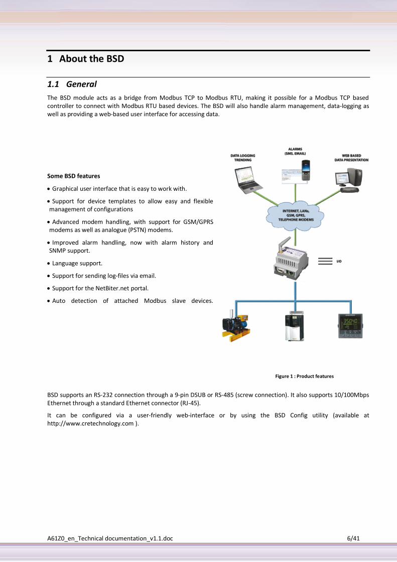
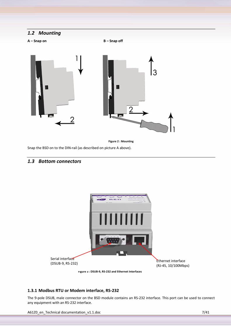
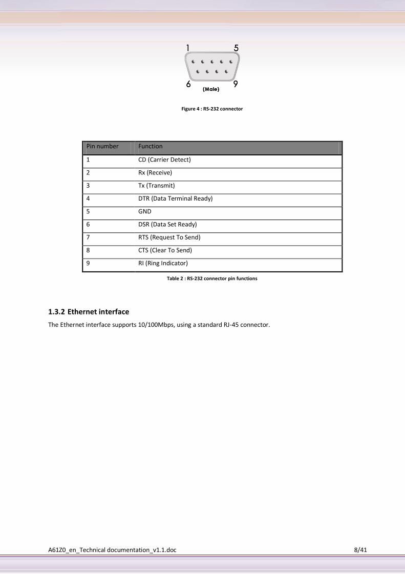
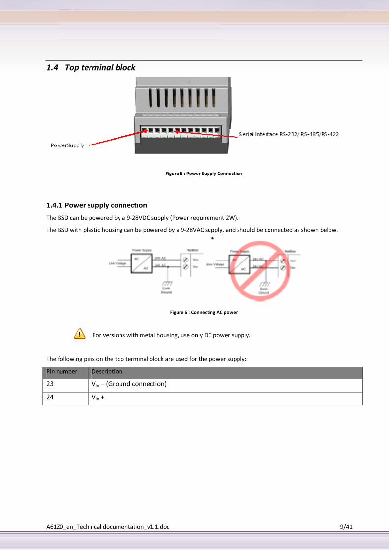
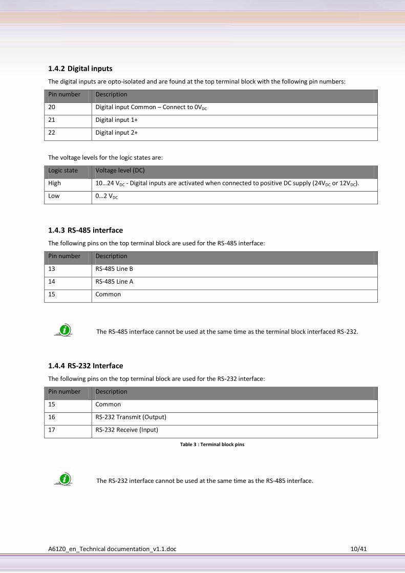
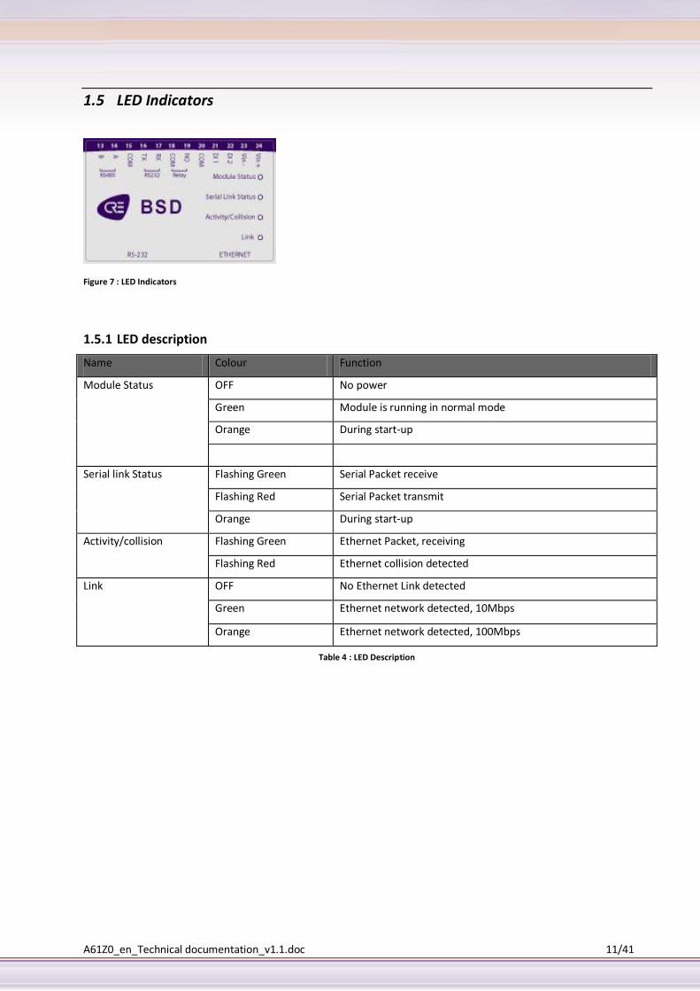
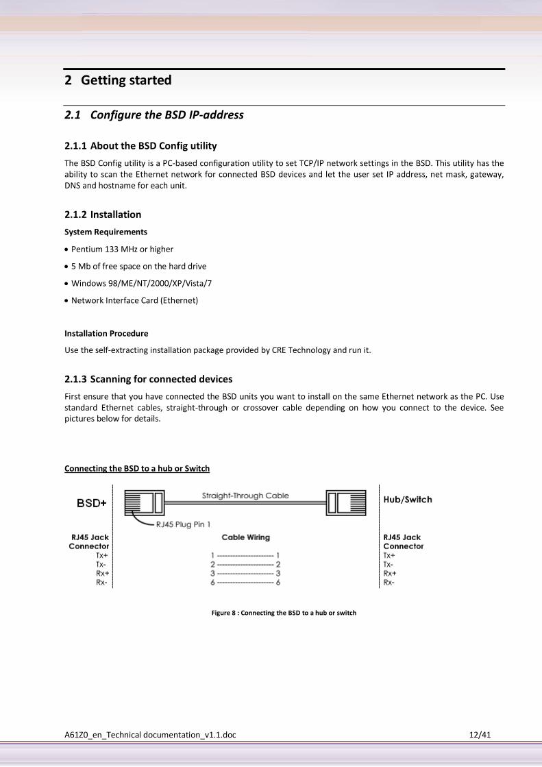
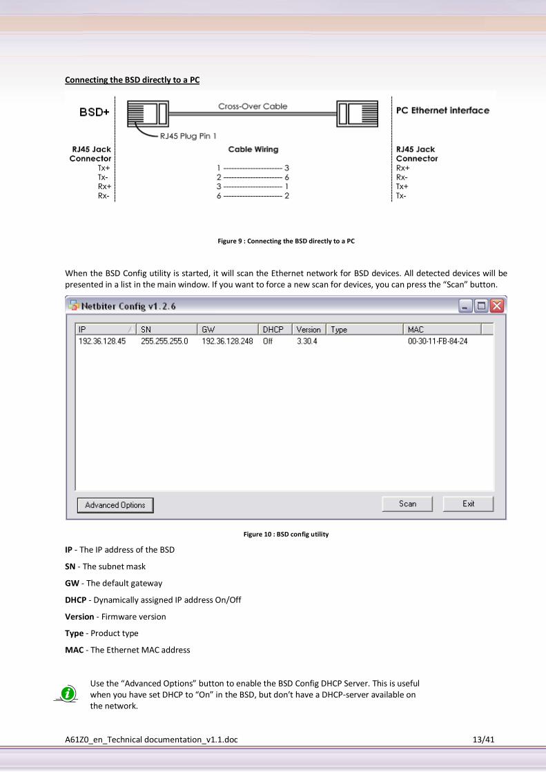
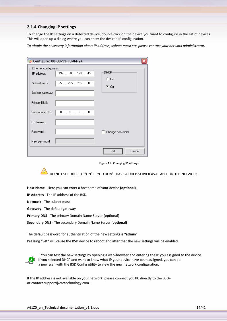
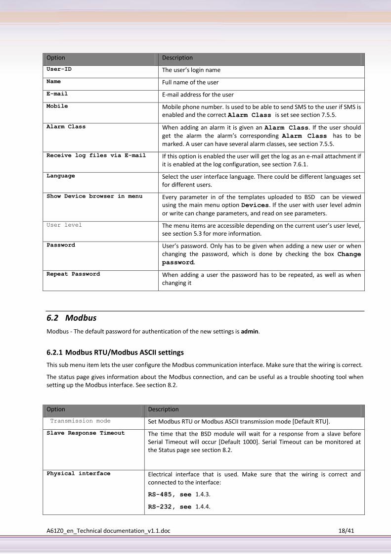
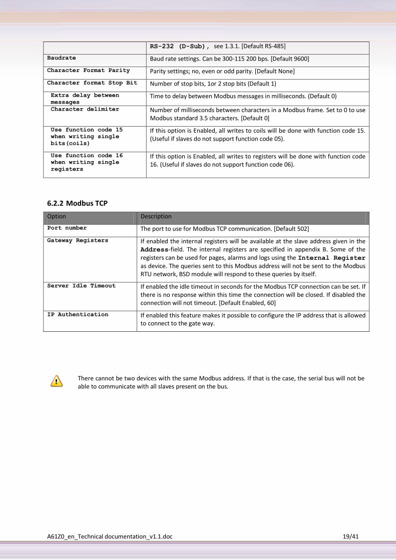
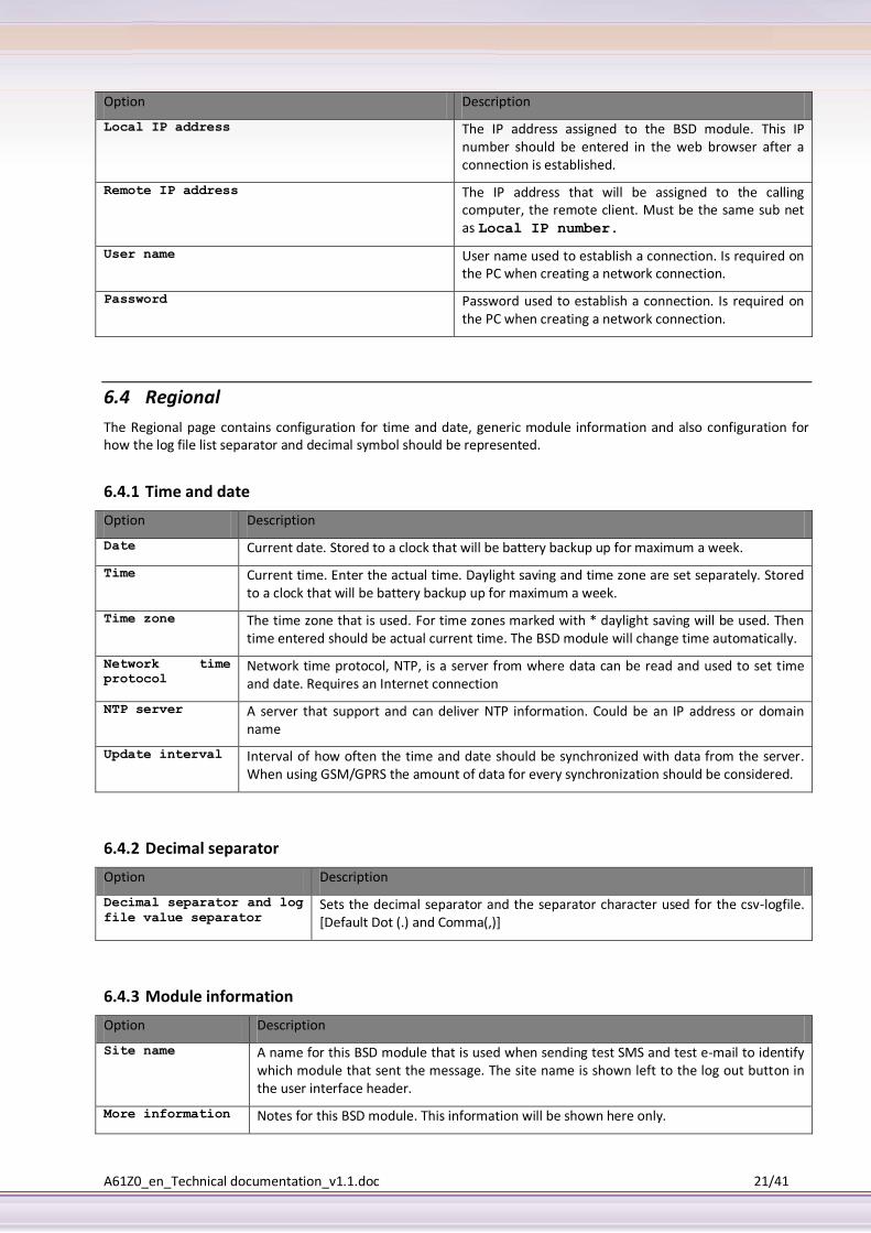
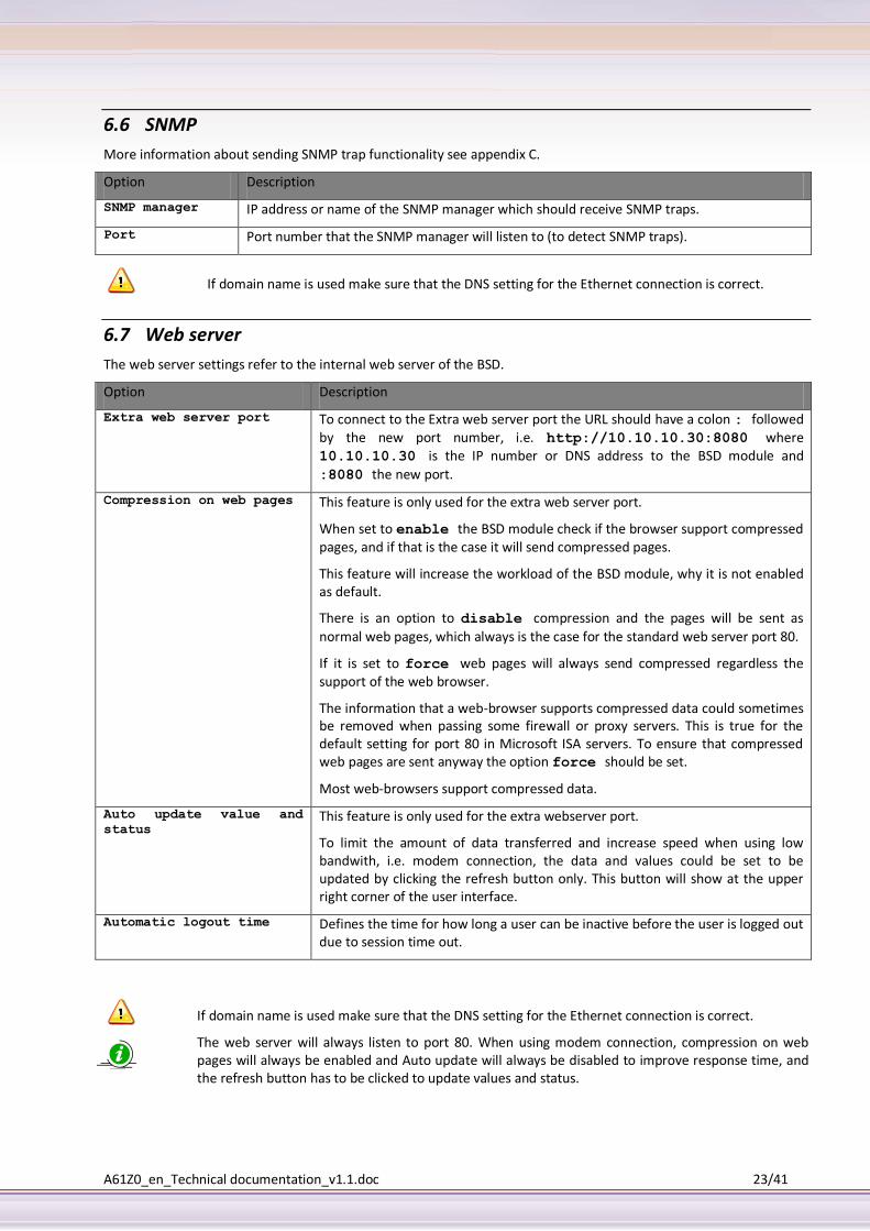
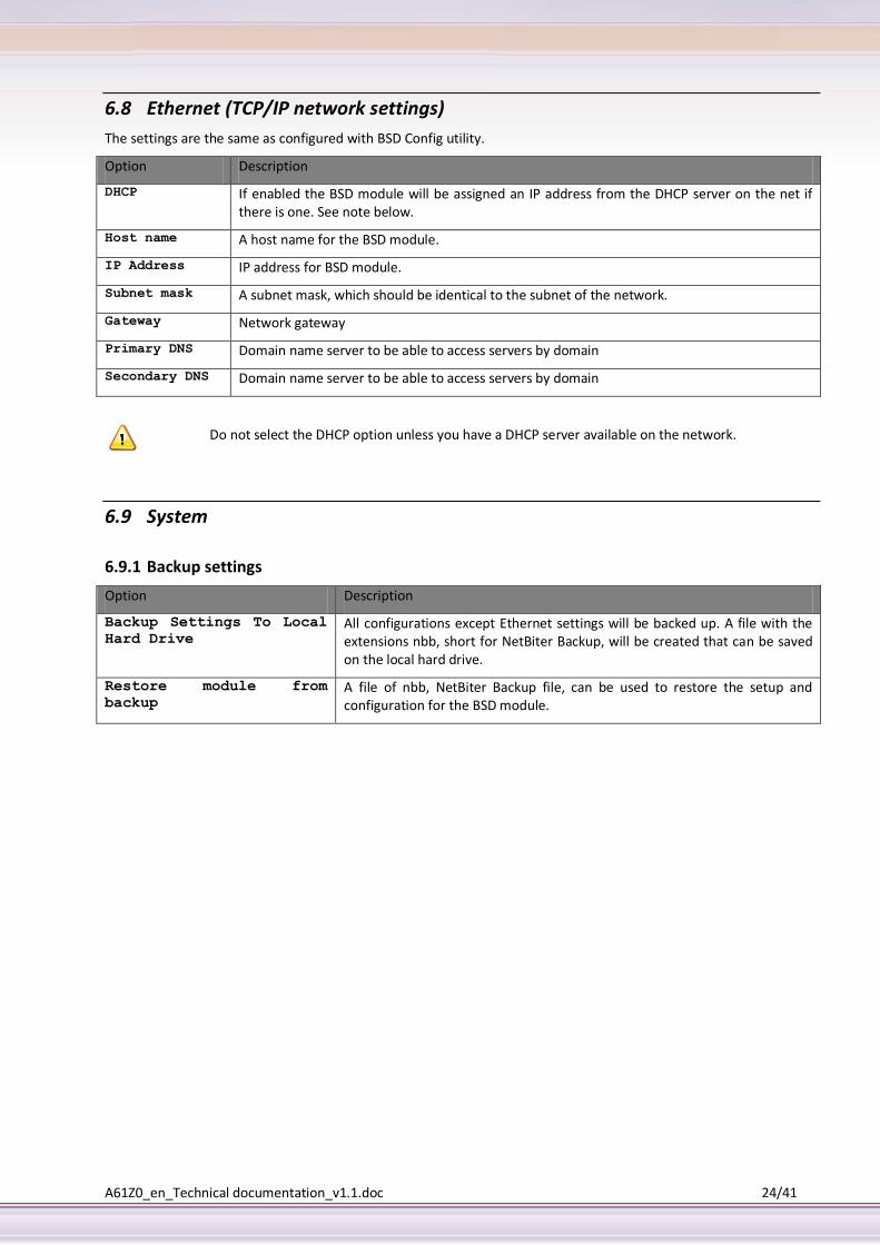
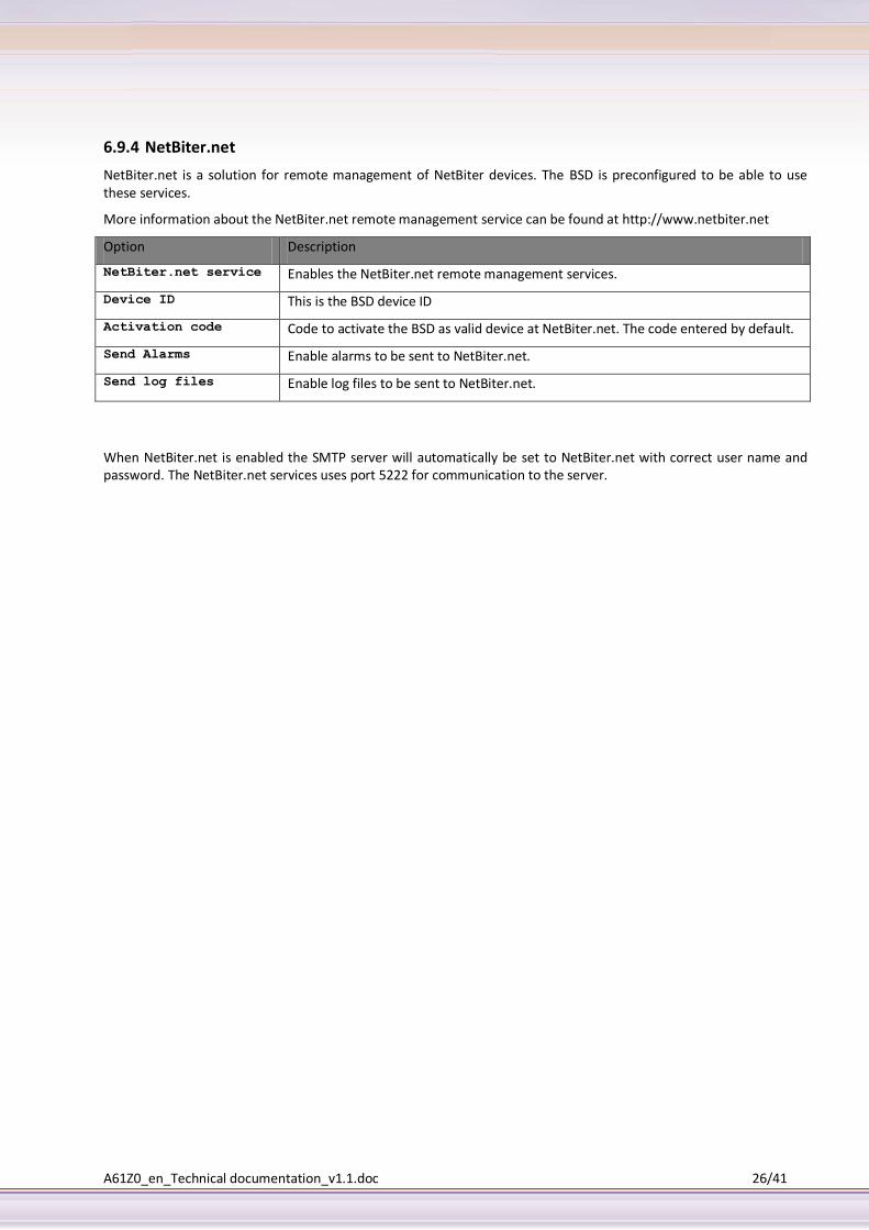
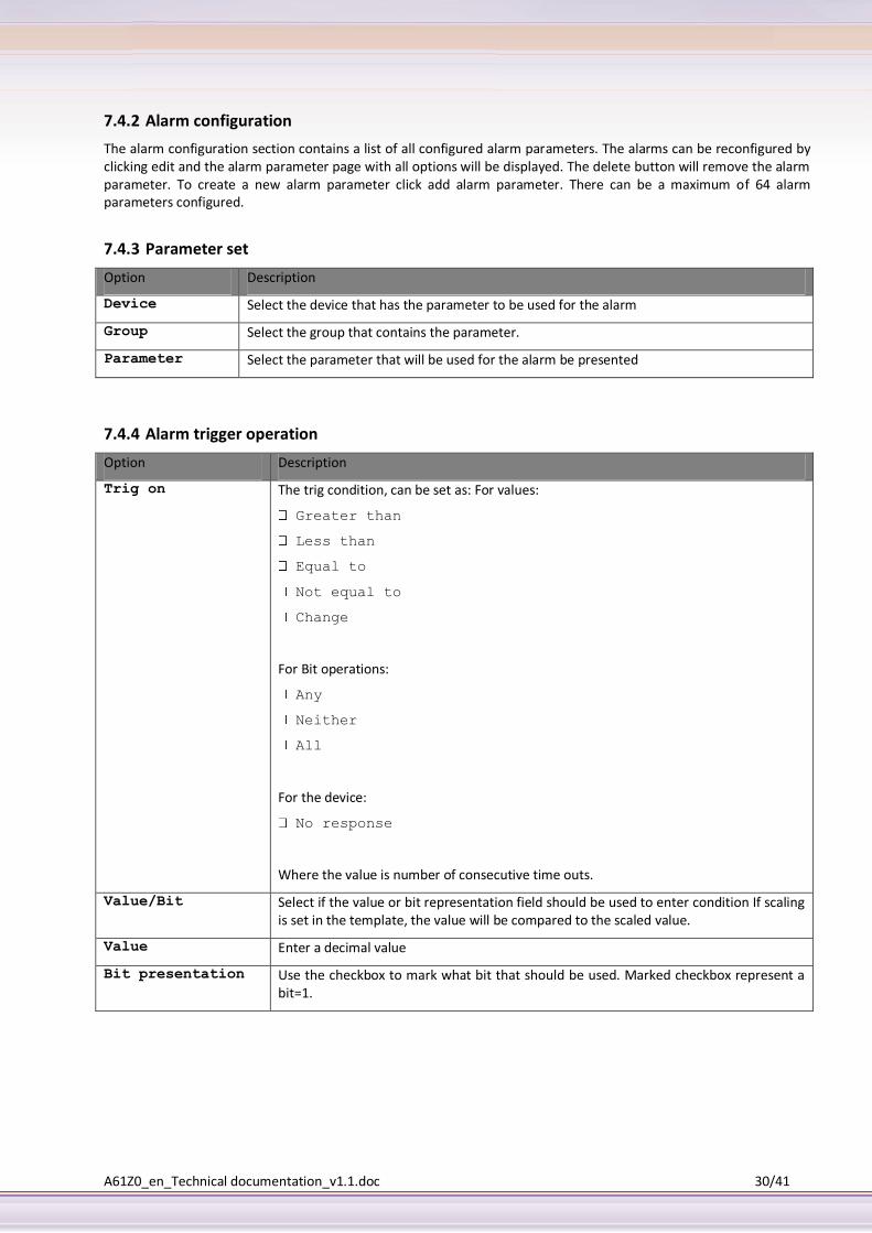
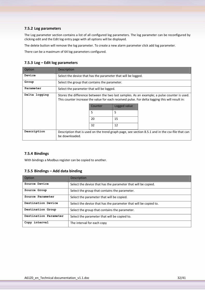
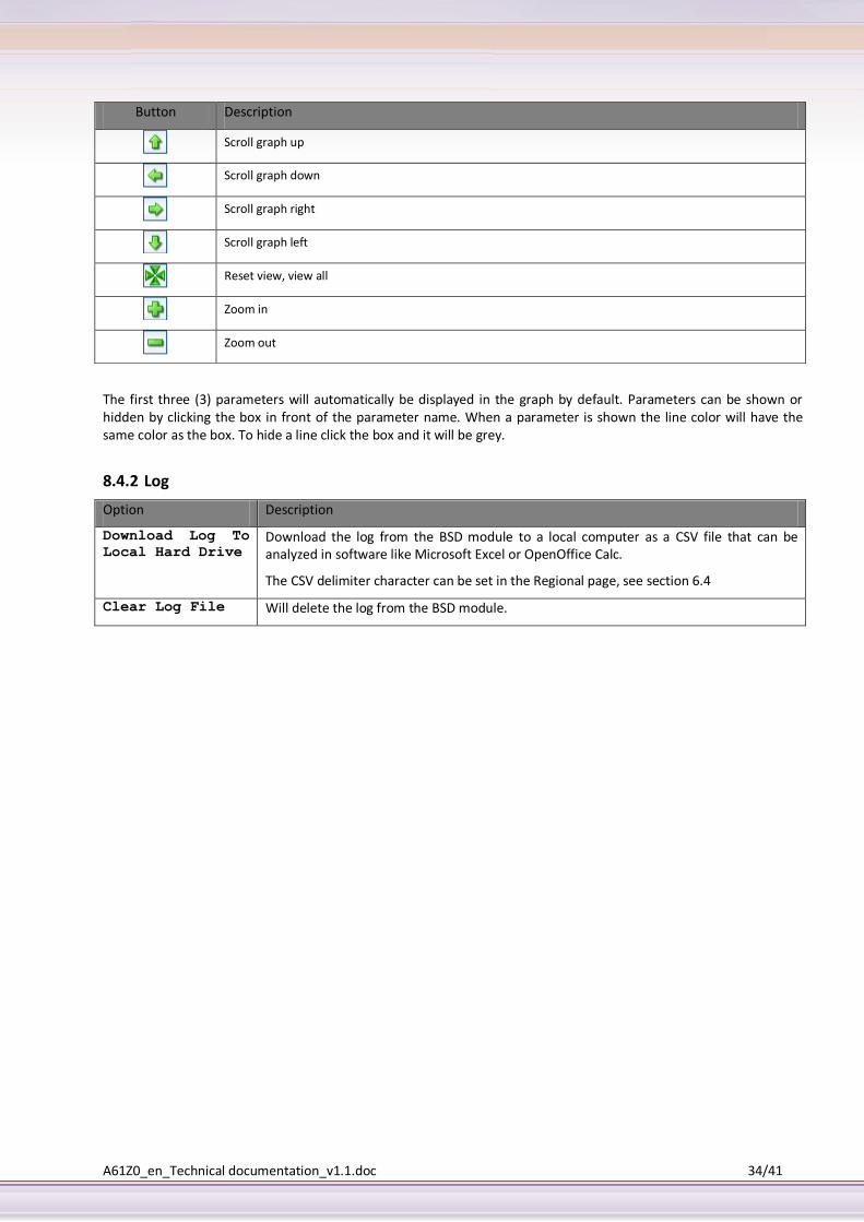
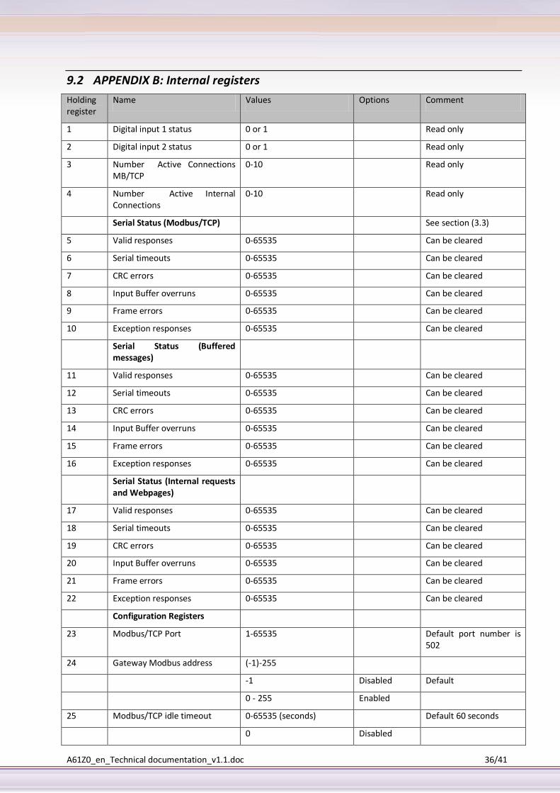
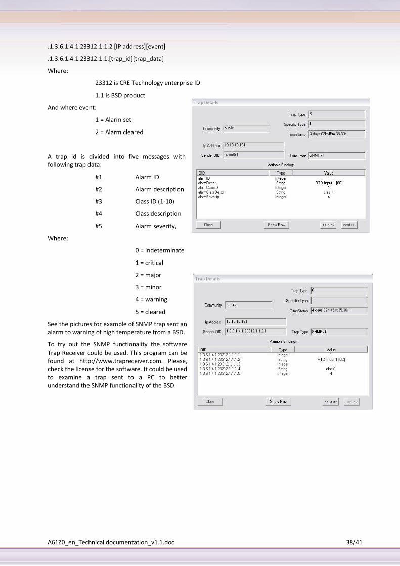