brzev ch13 ism
TRANSCRIPT

13-1
Chapter 13 - Solutions
__________________________________________________________________________
First, check whether the wall meets criteria related to the Empirical Method for bearing wall design (A23.3 Cl.14.2), as followsa) Solid rectangular cross section constant along the wall height.b), c) Wall is loaded concentrically.d) The wall is supported against lateral displacement at the top and bottom.In conclusion, the wall meets the above criteria and so the Empirical method can be used in the design.
1. Determine the wall thickness.
Wall thickness is restricted based on A23.3 Cl.14.1.7.1, as follows:
Therefore, the 180 mm value governs, however use
2. Check the bearing resistance.
13.1.
hu 4500mm=
thu25------ 4500
25------------ 180mm= =≥
t 150mm≥
t 200mm=
Copyright © 2006 Pearson Education Canada Inc.

13-2
The contact area is
Bearing resistance (A23.3 Cl.10.8.1) can be determined as
[12.28]
Since
okay
the wall bearing resistance is adequate.
3. Determine the factored axial load resistance.
• Determine the gross area of the wall section .
Determine according to A23.3 Cl.14.1.3.1.
i) bearing width
ii) will be determined by drawing the lines sloping downward from each side of the bearing
area - the slope is 2:1. Note that the value is limited by the intersection with the lines corre-sponding to the adjacent point loads.
(based on the intersecting points)
iii)
The smallest value governs, hence
A1( )
A1 200mm 200mm× 40000mm2= =
Br 0.85φcfc′A1=
0.85 0.65 25MPa 40000mm2××× 552kN==
Br 552kN Pf 300kN=>=
Ag( )
lb
a 200mm=
lb a 2 9t×+ 200 2 9 200××+ 3800mm= = =
lb
lb
lb 2500mm=
lb s≤ 2500mm=
lb 2500mm=
Copyright © 2006 Pearson Education Canada Inc.

13-3
Let us determine the gross area
• Determine the factored axial load resistance.
(pin supported wall)
Use [3.7]
(A23.3 Eq.14.1) [13.13]
Since
okay
the wall is adequate for the given loads.4. Determine the distributed and concentrated wall reinforcement.
• Distributed horizontal reinforcementi) Find the area of reinforcement.
Minimum required area of horizontal reinforcement (A23.3 Cl.14.1.8.6) can be determined as
ii) Determine the required bar spacing.
(15M bars, Table A.1)
[3.29]
Find the maximum permitted bar spacing according to A23.3 Cl.14.1.8.4.
In this case,
Horizontal reinforcement: [email protected]) Check whether one layer of reinforcement is adequate.
One layer is adequate when (A23.3 Cl.14.1.8.3). Since
Ag lb t× 2500mm 200mm× 500000mm2= = =
k 1.0=
α1 0.8≅
Pr23---α1φcfc′Ag 1
khu32t---------� �� �
2–=
23--- 0.8 0.65 25( MPa ) 500 103mm2×( ) 1 1 4500mm×
32 200×-------------------------------� �� �
2– 2191kN=××××=
Pr 2191kN Pf 300kN=>=
Ag 1000mm t× 1000mm 200mm× 200 103mm2×= = =
Ahmin 0.002Ag 0.002 200 103mm2×( ) 400mm2 m⁄= = =
Ab 200mm2=
s Ab1000
As------------≤ 200mm2 1000
400mm2 m⁄------------------------------× 500mm= =
s 500mm=
smax3t 3 200 600mm =×=
500mm governs←���
≤
s smax 500mm= =
t 210mm<
Copyright © 2006 Pearson Education Canada Inc.
13-4
okay
• Distributed vertical reinforcementi) Determine the area of vertical reinforcement.
Minimum area of vertical reinforcement (A23.3 Cl.14.1.8.5):
[13.1]
ii) Required bar spacing
(15M bars, Table A.1)
[3.29]
iii) Check whether the bar spacing is within the limits prescribed by CSA A23.3 (Cl.14.1.8.4).
Since
use
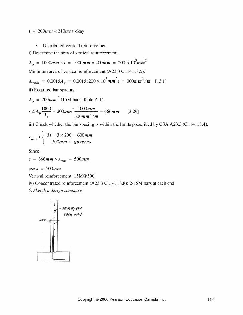
Vertical reinforcement: 15M@500iv) Concentrated reinforcement (A23.3 Cl.14.1.8.8): 2-15M bars at each end5. Sketch a design summary.
t 200mm 210mm<=
Ag 1000mm t× 1000mm 200mm× 200 103mm2×= = =
Avmin 0.0015Ag 0.0015 200 103mm2×( ) 300mm2 m⁄= = =
Ab 200mm2=
s Ab1000
As------------ 200mm2 1000mm
300mm2 m⁄------------------------------ 666mm= =≤
smax3t 3 200 600mm =×=
500mm governs←���
≤
s 666mm smax> 500mm= =
s 500mm=
Copyright © 2006 Pearson Education Canada Inc.

13-5
_________________________________________________________________________
First, check whether the wall meets criteria related to the Empirical Method for bearing wall design (A23.3 Cl.14.2), as followsa) Solid rectangular cross section constant along the wall heightb), c) The wall is concentrically loadedd) The wall is supported against lateral displacement at the top and bottomIn conclusion, the wall meets the above criteria and the Empirical Method can be used in this design.
1. Determine the wall thickness.
(A23.3 Cl.14.1.7.1)
Since
use .
2. Determine the factored axial load.
(NBC 2005 Table 4.1.3.2)
13.2.
hu 4000mm=
thu25------ 4000mm
25---------------------- 160mm= =≥
t 150mm≥
t 160mm=
DL 80kN m⁄=
LL 40kN= m⁄
wf 1.25DL 1.5LL+=
1.25 80kN m⁄ 1.5 40kNm
-------×+× 160kN m⁄==
Copyright © 2006 Pearson Education Canada Inc.

13-6
3. Determine the factored axial load resistance.
Find the gross area of the wall section (consider a strip of unit length ).
(pin supported wall)
[3.7]
(A23.3 Eq.14.1) [13.13]
Since
okay
The wall axial resistance is adequate for this design.
4. Determine the distributed and concentrated wall reinforcement.
• Distributed horizontal reinforcement.i) Find the minimum horizontal reinforcement area (A23.3 Cl.14.1.8.6).
ii) Find the required bar spacing.
(15M bars, Table A.1)
[3.29]
iii) Find the maximum permitted bar spacing (A23.3 Cl.14.1.8.4)
Use
Horizontal reinforcement: 15M@480iv) Check whether one layer of reinforcement is adequate.
One layer is adequate when , so
Ag( ) lb 1000mm=
Ag lb t× 1000mm 160mm× 160 103mm2×= = =
k 1.0=
α1 0.8≅
Pr23---α1φcfc′Ag 1
khu32t---------� �� �
2–=
23--- 0.8 0.65 25MPa 160 103mm2×( )×××× 1 1 4000mm×
32 160mm×-------------------------------� �� �
2– 540= kN m⁄=
Pr 540.3kN m⁄ wf> 160kN m⁄= =
Ag 1000 t× 1000 160× 160 103mm2×= = =
Ahmin 0.002Ag 0.002 160 103mm2×( ) 320mm2 m⁄= = =
Ab 200mm2=
s Ab1000
As------------≤ 200mm2 1000mm
320mm2 m⁄------------------------------ 625mm==
smax3t 3 160 480mm governs←=×=
500mm���
≤
s 480mm=
t 210mm<
Copyright © 2006 Pearson Education Canada Inc.

13-7
okay
• Distributed vertical reinforcementi) Find the minimum required area (A23.3 Cl.14.1.8.5).
(same as Step 4)
ii) Required bar spacing
(15M bars, Table A.1)
[3.29]
iii) Check whether the bar spacing is within the limits prescribed by CSA A23.3 (Cl.14.1.8.4).
Since
Use
Vertical reinforcement: 15M@480iv) Concentrated reinforcement at wall ends (A23.3 Cl.14.1.8.8): 2-15M bars at each end5. Sketch a design summary.
t 160mm 210mm<=
Ag 160 103mm2×=
Avmin 0.0015Ag 0.0015 160 103mm2×( ) 240mm2 m⁄= = =
Ab 200mm2=
s Ab1000
As------------ 200mm2 1000mm
240mm2 m⁄------------------------------× 833mm= =×≤
smax3t 3 160× 480mm governs←= =
500mm���
≤
s 833mm smax 480mm=>=
s 480mm=
Copyright © 2006 Pearson Education Canada Inc.
13-8
__________________________________________________________________________
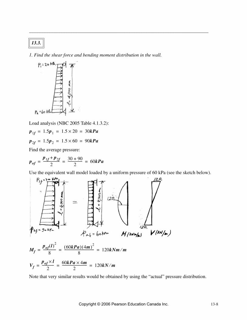
1. Find the shear force and bending moment distribution in the wall.
Load analysis (NBC 2005 Table 4.1.3.2):
Find the average pressure:
Use the equivalent wall model loaded by a uniform pressure of 60 kPa (see the sketch below).
Note that very similar results would be obtained by using the “actual” pressure distribution.
13.3.
p1f 1.5p1 1.5 20× 30kPa= = =
p2f 1.5p2 1.5 60× 90kPa= = =
pofp1f p2f+
2-------------------- 30 90+
2------------------ 60kPa= = =
Mfpof l( )2
8---------------- 60kPa( ) 4m( )2
8------------------------------------- 120kNm m⁄= = =
Vfpof l×
2--------------- 60kPa 4m×
2------------------------------- 120kN m⁄= = =
Copyright © 2006 Pearson Education Canada Inc.

13-9
2. Design the wall for flexure.
i) Find the effective depth .
Use 20M bars
cover (interior exposure, Table A.2)
(wall thickness)
ii) Find the required moment resistance.
Set
iii) Find the required area of vertical tension reinforcement.
Design the wall for flexure based on a strip of unit width .
Find the reinforcement area - use the direct method.
[5.4]
iv) Select the amount of reinforcement in terms of size and spacing.
Use 20M bars see Table A.1
[3.29]
v) Find the maximum permitted bar spacing (A23.3 Cl.14.1.8.4)
Since
Use .
Vertical reinforcement: 20M@200vi) Confirm that the CSA A23.3 maximum tension reinforcement (Cl.10.5.2) requirement has been satisfied.Actual reinforcement area:
d
db 20mm=( )
20mm=
t 300mm=
d t cover–db2-----– 300 20– 20
2------– 270mm= = =
Mr Mf 240kNm m⁄= =
b 1000mm=
As 0.0015fc′b d d2 3.85Mrfc′b
------------------––� �� � �
=
0.0015 25MPa 1000mm 270 270( )2 3.85 120 106×( )×25MPa( ) 1000mm( )
---------------------------------------------------––� �� � �
1377mm2 m⁄=××=
Ab 300mm2=( )
s Ab1000
As------------ 300mm2( )=× 1000mm
1377mm2------------------------ 218mm=≤
smax3t 3 300 900mm =×=
500mm governs←���
≤
s 218mm smax 500mm=<=
s 200mm=
Copyright © 2006 Pearson Education Canada Inc.
13-10
Reinforcement ratio:
[3.1]
Balanced reinforcement ratio:
Since
okay
vii) Check the CSA A23.3 minimum reinforcement requirement (Cl.14.1.8.5).
[13.1]
Since
okay
The vertical reinforcement is adequate.
3. Design the wall for shear.
Design shear force is
a) Concrete shear resistance .
Find the effective shear depth :
So,
(larger value governs)
Set (unit strip)
Find (A23.3 Cl.11.3.6.3b).
(A23.3 Eq.11.9) [6.13]
As Ab1000
s------------ 300mm2( )1000mm
200mm---------------------- 1500mm2 m⁄===
ρAsbd------ 1500mm2
1000mm 270mm×----------------------------------------------- 0.0055= = =
ρb 0.022= fc′ 25MPa Table A.4,=( )
ρ 0.0055 ρb 0.022=<=
Ag 1000mm t× 1000mm 300mm× 300 103mm2×= = =
Avmin 0.0015Ag=
0.0015 300 103mm2×( ) 450mm2 m⁄==
As 1500mm2= m⁄ 450mm2 m⁄>
Vf 120kN m⁄=
Vc( )
dv( )
dv0.9d0.72t
0.9 270mm×0.72 300mm×
243mm216mm
= = =
dv 243mm 240mm≅=
bw 1000mm=
β
β 2301000 dv+-----------------------=
Copyright © 2006 Pearson Education Canada Inc.

13-11
Find .
(A23.3 Eq.11.6) [6.12]
b) Is shear reinforcement required?According to A23.3 Cl.11.2.8.1, shear reinforcement is not required when
Since
it follows that the shear reinforcement is not required, however CSA A23.3 Code requires mini-mum provision of horizontal reinforcement in walls.
c) Determine the minimum distributed horizontal reinforcement.i) Reinforcement area (A23.3 Cl.14.1.8.6)
ii) Determine the required bar spacing.
20M bars:
[3.29]
iii) Check whether the spacing is within the limits prescribed by CSA A23.3 (Cl.14.1.8.4).
Since
okay
Horizontal reinforcement: 15M@500iv) Check whether one layer of reinforcement is adequate.According to A23.3 Cl.14.1.8.3, one layer of reinforcement is adequate when the wall thickness is less than 210 mm, that is, . In this case, . Therefore, two layers of rein-
2301000 240+--------------------------- 0.185 0.18≅==
Vc
Vc φcλβ fc′bwdv=
0.65 1.0( ) 0.18( ) 25MPa 1000mm( ) 240mm( )= 140kN m⁄=
Vf Vc≤
Vf 120kN m⁄= Vc 140kN m⁄=<
Ag 1000mm t× 1000mm 300mm× 300 103mm2×= = =
Ahmin 0.002Ag=
0.002 300 103mm2×( ) 600mm2 m⁄==
Ab 300mm2, Table A.1=( )
s Ab1000
As------------ 300mm2 1000mm
600mm2----------------------× 500mm= =≤
s 500mm=
smax3t 3 300 900mm =×=
500mm governs←���
≤
s smax 500mm= =
t 210mm< t 300mm=
Copyright © 2006 Pearson Education Canada Inc.

13-12
forcement are required. Instead of using 20M bars for horizontal reinforcement, it would be bet-ter to use 15M bars.For 2-15M bars at 500 mm spacing, the area is
Since
Use 2 layers of horizontal reinforcement, that is, 15M@500.
4. Sketch a design summary.
Note that one layer of vertical reinforcement has been specified at the exterior wall face (15M@500) in order to satisfy the requirement for 2 layers of reinforcement. The main vertical tension reinforcement for this wall is located at the interior face.
Ab 2 200 400mm2=×=
As Ab1000
s------------ 400mm2( ) 1000mm
500mm----------------------× 800mm2 m⁄= = =
As 800mm2= m⁄ 600mm2 m⁄>
Copyright © 2006 Pearson Education Canada Inc.

13-13
_________________________________________________________________________
a) Design the wall for the given reinforcement.
1. Determine the design bending moments and shear forces in the wall.
Load analysis (NBC 2005 Table 4.1.3.2):
Find the sum of moments about the support B as
So, the reaction at point A is equal to
The resultant of lateral load can be calculated as (see the sketch above)
Find the reaction at point B from the equilibrium of lateral forces as
or
13.4.
pf 1.5 30× kNm2------- 45kN
m2-------= =
ΣMB
45kNm2------- 4m×
2----------------------------
� �� � � � �
4m3
--------� �� � A 3m( )– 0= =
A 40kN=
R45kN
m2-------
� �� � 4m×
2---------------------------------- 90kN==
ΣH A B R 0=–+=
Copyright © 2006 Pearson Education Canada Inc.
13-14
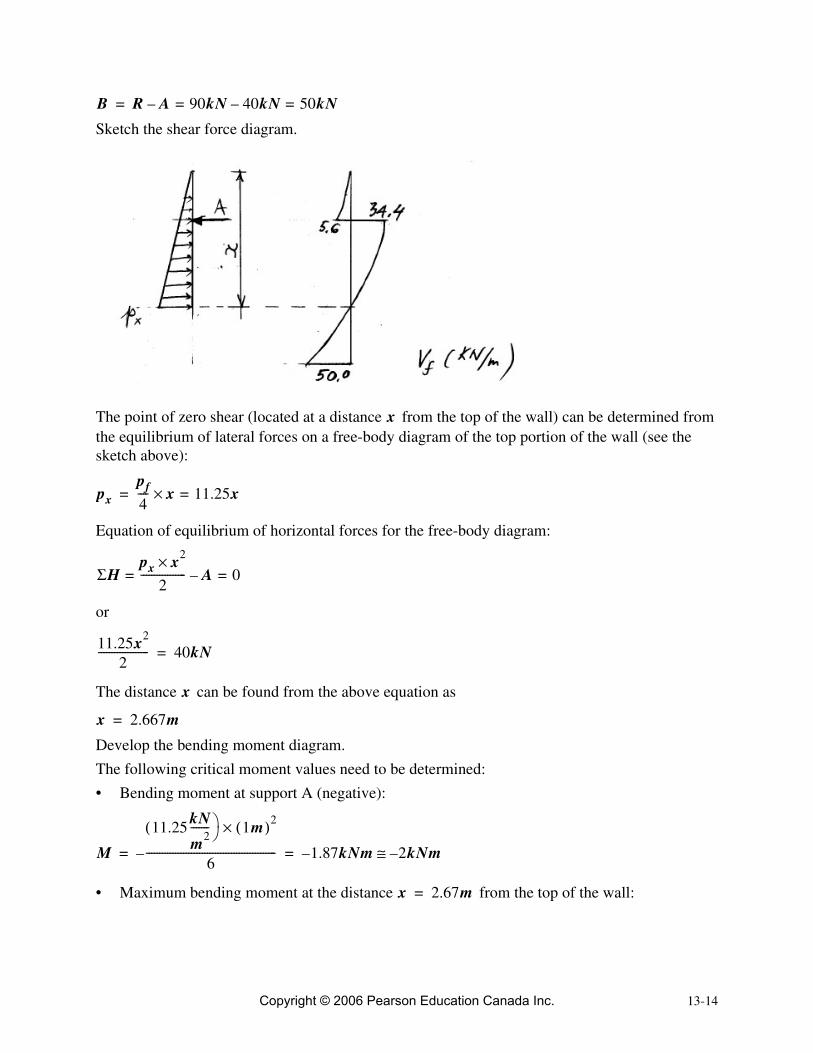
Sketch the shear force diagram.
The point of zero shear (located at a distance from the top of the wall) can be determined from the equilibrium of lateral forces on a free-body diagram of the top portion of the wall (see the sketch above):
Equation of equilibrium of horizontal forces for the free-body diagram:
or
The distance can be found from the above equation as
Develop the bending moment diagram.The following critical moment values need to be determined:• Bending moment at support A (negative):
• Maximum bending moment at the distance from the top of the wall:
B R A– 90= kN 40kN 50kN=–=
x
pxpf4---- x 11.25x=×=
ΣHpx x2×
2----------------- A 0=–=
11.25x2
2------------------- 40kN=
x
x 2.667m=
M11.25( kN
m2-------
�� 1m( )2×
6-------------------------------------------------– 1.87kNm 2kNm–≅–= =
x 2.67m=
Copyright © 2006 Pearson Education Canada Inc.

13-15
2. Design the wall for flexure.
Find the effective depth .
Estimate (reinforcement located in the middle of the wall - 1 layer).
Section at the midspan (maximum positive bending moment)Find the required moment resistance.
Set
Find the required area of vertical tension reinforcement.
Design the wall for flexure based on a strip of unit width .
Find the reinforcement area - use the direct method.
[5.4]
Select the amount of reinforcement in terms of size and spacing.
Use 20M bars see Table A.1
[3.29]
M11.25kN
m2------- 2.67m( )×
2
6--------------------------------------------------– 40kN( ) 1.67m( )+ 53kNm= =
d
d 100mm=
Mr Mf 53kNm m⁄= =
b 1000mm=
As 0.0015fc′b d d2 3.85Mrfc′b
------------------––� �� � �
=
0.0015 25MPa( ) 1000mm( ) 100mm 100mm2 3.85 53 106×( )25MPa 1000mm( )----------------------------------------------––
� �� � �
=
2142mm2 m⁄=
Ab 300mm2=
s Ab1000
As------------ 300mm2( )=× 1000mm
2142mm2------------------------ 140mm=≤
Copyright © 2006 Pearson Education Canada Inc.

13-16
iii) Find the maximum permitted bar spacing (A23.3 Cl.14.1.8.4)
Since
Use .
Vertical reinforcement: 20M@140Confirm that the CSA A23.3 maximum tension reinforcement requirement (Cl.10.5.2) has been satisfied.Reinforcement ratio:
[3.1]
Balanced reinforcement ratio:
Since
This amount of reinforcement is acceptable per CSA A23.3, however it is considered to be large as it is very close to the balanced reinforcement.Check the CSA A23.3 minimum reinforcement requirement (Cl.14.1.8.5).
[13.1]
Since
okay
Section at the support A (negative bending moment)Find the required moment resistance.
Set
Find the reinforcement area - use the direct method.
[5.4]
smax3t 3 200 600mm =×=
500mm governs←���
≤
s 140mm smax 500mm=<=
s 140mm=
ρAsbd------ 2142mm2
1000mm 100mm×----------------------------------------------- 0.0214= = =
ρb 0.022= fc′ 25MPa Table A.4,=( )
ρ 0.0214 ρb 0.022=<=
Ag 1000mm t× 1000mm 200mm× 200 103mm2×= = =
Avmin 0.0015Ag=
0.0015 200 103mm2×( ) 300mm2 m⁄==
As 2143mm2= m⁄ 300mm2 m⁄>
Mr Mf 2kNm m⁄= =
As 0.0015fc′b d d2 3.85Mrfc′b
------------------––� �� � �
=
Copyright © 2006 Pearson Education Canada Inc.

13-17
Select the amount of reinforcement in terms of size and spacing.
Use 15M bars see Table A.1
[3.29]
(A23.3 Cl.14.1.8.4, same as for other section)
Since
Use .
Find the actual reinforcement area.
Check the CSA A23.3 minimum reinforcement requirement (Cl.14.1.8.5).
[13.1]
Since
okay
Vertical reinforcement: 15M@500.
3. Design the wall for shear.
Design shear force:
• Concrete shear resistance .
Find the effective shear depth :
So,
(larger value governs)
As 0.0015 25( ) 1000( ) 100 1002 3.85 2 106×( )25 1000( )
---------------------------------––� �� � �
58mm2 m⁄==
Ab 200mm2=
s Ab1000
As------------ 200mm2( )=× 1000mm
58mm2---------------------- 3448mm=≤
smax 500mm=
s 3448mm smax 500mm=>=
s 500mm=
As Ab1000
s------------ 200mm2( ) 1000mm
500mm----------------------× 400mm2 m⁄= = =
Ag 1000mm t× 1000mm 200mm× 200 103mm2×= = =
Avmin 0.0015Ag=
0.0015 200 103mm2×( ) 300mm2 m⁄==
As 400mm2= m⁄ 300mm2 m⁄>
Vf 50kN m⁄=
Vc( )
dv( )
dv0.9d0.72t
0.9 100mm×0.72 200mm×
90mm144mm
= = =
dv 140mm≅
Copyright © 2006 Pearson Education Canada Inc.

13-18
Set (unit strip)
Find (A23.3 Cl.11.3.6.3b).
(A23.3 Eq.11.9) [6.13]
Find .
(A23.3 Eq.11.6) [6.12]
• Is shear reinforcement required?According to A23.3 Cl.11.2.8.1, shear reinforcement is not required when
Since
it follows that the shear reinforcement is not required, however CSA A23.3 Code requires mini-mum provision of horizontal reinforcement in walls.
• Determine the minimum distributed horizontal reinforcement.i) Reinforcement area (A23.3 Cl.14.1.8.6)
ii) Determine the required bar spacing.
15M bars
[3.29]
iii) Check whether the spacing is within the limits prescribed by CSA A23.3 (Cl.14.1.8.4).
Since
bw 1000mm=
β
β 2301000 dv+-----------------------=
2301000 140+--------------------------- 0.2==
Vc
Vc φcλβ fc′bwdv=
0.65 1.0( ) 0.2( ) 25MPa 1000mm( ) 140mm( )= 91kN m⁄=
Vf Vc≤
Vf 50kN m⁄= Vc 91kN m⁄=<
Ag 1000mm t× 1000mm 200mm× 200 103mm2×= = =
Ahmin 0.002Ag=
0.002 200 103mm2×( ) 400mm2 m⁄==
Ab 200mm2, Table A.1=( )
s Ab1000
As------------ 200mm2 1000mm
400mm2----------------------× 500mm= =≤
s 500mm=
smax3t 3 200 600mm =×=
500mm governs←���
≤
Copyright © 2006 Pearson Education Canada Inc.

13-19
okay
Horizontal reinforcement: 15M@500
4. Sketch a design summary.
b) Comment on the effectiveness of placing the reinforcement in the middle of the wall.It is convenient to place vertical reinforcement in the middle of the wall; in this way, the wall is able to resist both positive and negative bending moments without adjusting the location of rein-forcing steel to suit the moment diagram. This is a good approach to save labour cost on site, as well as to reduce complexities of reinforcement installation and minimize chances for field errors.
c) Does this reinforcement strategy represent the most cost-effective solution?The required amount of vertical reinforcement placed in the middle of the wall is very large (very close to the balanced reinforcement). In order to reduce the amount of reinforcement, an alterna-tive solution can be considered wherein the reinforcement is placed close to the inside wall face. This will result in an increased effective depth which will in turn result in a reduced amount of vertical reinforcement.When the reinforcement is moved to the inside face of the wall, the effective depth can be esti-mated as
Consider the section with the maximum bending moment, where
Find the required area of vertical tension reinforcement- use the direct method.
s smax 500mm= =
d 200mm 35mm–≅ 165mm=
Mr Mf 53kNm m⁄= =
Copyright © 2006 Pearson Education Canada Inc.

13-20
[5.4]
Select the amount of reinforcement in terms of size and spacing.
Use 15M bars ( , see Table A.1)
[3.29]
Use [email protected] alternative solution results in significantly smaller amount of vertical reinforcement - there is a 50% reduction in the total reinforcement area (1009 mm2 versus 2142 mm2).Vertical wall elevation and the reinforcement arrangement is presented below.
As 0.0015fc′b d d2 3.85Mrfc′b
------------------––� �� � �
=
0.0015 25MPa( ) 1000mm( ) 165 165mm2 3.85 53 106×( )25MPa 1000mm( )----------------------------------------------––
� �� � �
=
1009mm2 m⁄=
Ab 200mm2=
s Ab1000
As------------ 200mm2( )=× 1000mm
1009mm2------------------------ 198mm=≤
Copyright © 2006 Pearson Education Canada Inc.

13-21
_________________________________________________________________________
a) Draw the bending moment diagram for the wall and the footing.Gravity load effectsFactored axial load (NBC 2005 Table 4.1.3.2)
Eccentricity
Factored bending moment:
Axial forces in the slabs (see the sketch above):
Bending moment diagram is shown on the sketch below.
Lateral load effectsFactored soil pressure (NBC 2005 Table 4.1.3.2)
13.5.
Pf 1.25P 1.25 150 188kN m⁄=×==
e 1m3
-------- 0.25m2
---------------– 0.2m= =
Mf Pf e× 188= kNm
------- 0.2m× 38kNmm
------------= =
T CMfh
------- 38kNm m⁄3m
--------------------------- 12.5kN m⁄= = = =
pf 1.5 20kPa× 30kPa= =
Copyright © 2006 Pearson Education Canada Inc.

13-22
Bending moment diagram is shown on the sketch below.
Combined gravity and lateral loadsShear force diagram is obtained using the principle of superposition, by combining the corre-sponding shear force values for gravity and lateral loads (see below).
Maximum bending moment develops at the point of zero shear (distance 1.08 m from the top of the wall). The corresponding value can be obtained as follows
Mfpf h2×
8---------------- 30kPa( ) 3m( )2×
8------------------------------------------- 33.8kNm m⁄= = =
Mf 32.5kN m⁄( ) 1.08m( ) 30kN m⁄( ) 1.08m( )2
2---------------------- 17.6kNm m⁄=×–×=
Copyright © 2006 Pearson Education Canada Inc.

13-23
Bending moment diagram due to combined gravity and lateral loads is shown below.
Find the inflection point located at a distance from the base of the wall (see the sketch above). Bending moment at a distance from the base of the wall is equal to zero, that is,
or
The solution of this quadratic equation is
b) Design the flexural reinforcement for the footing and the exterior wall face.
Find the effective depth .
Use 20M bars
Footing:
cover (Table A.2)
(footing thickness)
Wall:
cover (exterior exposure, Table A.2)
(wall thickness)
xMx x
Mx 38– 57.5 x( ) 30 x( )2
2----------–+ 0= =
15x2 57.5x– 38+ 0=
x 0.85m=
d
db 20mm=( )
75mm=
t 300mm=
d t cover–db2-----– 300 75– 20
2------– 215mm= = =
50mm=
t 250mm=
Copyright © 2006 Pearson Education Canada Inc.

13-24
Use
for the design (smaller value).
Find the required moment resistance.
Set
Find the required area of vertical tension reinforcement.
Design the wall for flexure based on a strip of unit width .
Find the reinforcement area - use the direct method.
[5.4]
Select the amount of reinforcement in terms of size and spacing.
Use 20M bars see Table A.1
[3.29]
Find the maximum permitted bar spacing (A23.3 Cl.14.1.8.4)
Since
Use .
Vertical reinforcement: 20M@450Confirm that the CSA A23.3 maximum tension reinforcement requirement (Cl.10.5.2) has been satisfied.Actual reinforcement area:
Reinforcement ratio:
d t cover–db2-----– 250 50– 20
2------– 190mm= = =
d 190mm=
Mr Mf 38kNm m⁄= =
b 1000mm=
As 0.0015fc′b d d2 3.85Mrfc′b
------------------––� �� � �
=
0.0015 25MPa 1000mm 190 190( )2 3.85 38 106×( )×25MPa( ) 1000mm( )
---------------------------------------------------––� �� � �
603mm2 m⁄=××=
Ab 300mm2=( )
s Ab1000
As------------ 300mm2( )=× 1000mm
603mm2---------------------- 497mm 450mm≅=≤
smax3t 3 250 750mm =×=
500mm governs←���
≤
s 450mm smax 500mm=<=
s 450mm=
As Ab1000
s------------ 300mm2( )1000mm
450mm---------------------- 667mm2 m⁄===
Copyright © 2006 Pearson Education Canada Inc.

13-25
[3.1]
Balanced reinforcement ratio:
Since
okay
Check the CSA A23.3 minimum reinforcement requirement (Cl.14.1.8.5).
[13.1]
Since
okay
The vertical reinforcement is adequate.Determine the reinforcement length for the wall (above the footing-wall interface).Development length for 20M bars in this example (bottom bars, regular uncoated bars, normal-density concrete) can be determined from Table A.5 as
A23.3 Cl.12.11.3 (as applied to continuous beams) states that (see Section 9.7.8)
(A23.3 Eq.12-6) [9.8]
where
(greater value governs)
So,
Since
okay
Therefore, the total wall reinforcement length above the wall-footing interface can be obtained as
ρAsbd------ 667mm2
1000mm 190mm×----------------------------------------------- 0.0035= = =
ρb 0.022= fc′ 25MPa Table A.4,=( )
ρ 0.0035 ρb 0.022=<=
Ag 1000mm t× 1000mm 250mm× 250 103mm2×= = =
Avmin 0.0015Ag=
0.0015 250 103mm2×( ) 375mm2 m⁄==
As 667mm2= m⁄ 375mm2 m⁄>
ld 575mm=
ldMrVf------- la+≤
lad
12db
190mm12 20mm 240mm=×
= =
la 240mm=
ld38kNm57.5kN------------------- 0.24m+ 0.66m 0.24m+ 0.9= m 900mm==≤
ld 575mm 900mm<=
Copyright © 2006 Pearson Education Canada Inc.

13-26
c) Design the vertical and horizontal reinforcement at the interior wall face.
1. Design the wall for flexure.
Find the effective depth .
cover (interior exposure, Table A.2)
(wall thickness)
Find the required moment resistance.
Set
Find the required area of vertical tension reinforcement.
Design the wall for flexure based on a strip of unit width .
Find the reinforcement area - use the direct method.
[5.4]
Select the amount of reinforcement in terms of size and spacing.
Use 15M bars ( , see Table A.1)
[3.29]
Find the maximum permitted bar spacing (A23.3 Cl.14.1.8.4)
Since
Use .
Vertical reinforcement: 15M@500
l 0.85m 0.575m+ 1.425m 1.5m≅= =
d
20mm=
t 250mm=
d t cover–db2-----– 250 20– 20
2------– 220mm= = =
Mr Mf 18kNm m⁄≅=
b 1000mm=
As 0.0015fc′b d d2 3.85Mrfc′b
------------------––� �� � �
=
0.0015 25MPa 1000mm 220 220( )2 3.85 18 106×( )×25MPa( ) 1000mm( )
---------------------------------------------------––� �� � �
240mm2 m⁄=××=
Ab 200mm2=
s Ab1000
As------------ 200mm2( )=× 1000mm
240mm2---------------------- 833mm=≤
smax3t 3 250 750mm =×=
500mm governs←���
≤
s 833mm smax 500mm=>=
s 500mm=
Copyright © 2006 Pearson Education Canada Inc.

13-27
Confirm that the CSA A23.3 maximum tension reinforcement requirement (Cl.10.5.2) has been satisfied.Actual reinforcement area:
Reinforcement ratio:
[3.1]
Balanced reinforcement ratio:
Since
okay
Check the CSA A23.3 minimum reinforcement requirement (Cl.14.1.8.5).
[13.1]
Since
okay
The vertical reinforcement is adequate.
2. Design the wall for shear.
Design shear force:
• Concrete shear resistance .
Find the effective shear depth :
So,
(larger value governs)
Set (unit strip)
Find (A23.3 Cl.11.3.6.3b).
As Ab1000
s------------ 200mm2( )1000mm
500mm---------------------- 400mm2 m⁄===
ρAsbd------ 400mm2
1000mm 220mm×----------------------------------------------- 0.0018= = =
ρb 0.022= fc′ 25MPa Table A.4,=( )
ρ 0.0018 ρb 0.022=<=
Ag 1000mm t× 1000mm 250mm× 250 103mm2×= = =
Avmin 0.0015Ag=
0.0015 250 103mm2×( ) 375mm2 m⁄==
As 400mm2= m⁄ 375mm2 m⁄>
Vf 57.5kN m⁄=
Vc( )
dv( )
dv0.9d0.72t
0.9 220mm×0.72 250mm×
198mm180mm
= = =
dv 200mm≅
bw 1000mm=
β
Copyright © 2006 Pearson Education Canada Inc.

13-28
(A23.3 Eq.11.9) [6.13]
Find .
(A23.3 Eq.11.6) [6.12]
• Is shear reinforcement required?According to A23.3 Cl.11.2.8.1, shear reinforcement is not required when
Since
it follows that the shear reinforcement is not required, however CSA A23.3 Code requires mini-mum provision of horizontal reinforcement in walls.
• Determine the minimum distributed horizontal reinforcement.i) Reinforcement area (A23.3 Cl.14.1.8.6)
ii) Determine the required bar spacing.
15M bars
[3.29]
iii) Check whether the spacing is within the limits prescribed by CSA A23.3 (Cl.14.1.8.4).
Since
Use .
Horizontal reinforcement: 15M@400
β 2301000 dv+-----------------------=
2301000 200+--------------------------- 0.19==
Vc
Vc φcλβ fc′bwdv=
0.65 1.0( ) 0.19( ) 25MPa 1000mm( ) 200mm( )= 123.5kN m⁄=
Vf Vc≤
Vf 57.5kN m⁄= Vc 123.5kN m⁄=<
Ag 1000mm t× 1000mm 250mm× 250 103mm2×= = =
Ahmin 0.002Ag=
0.002 250 103mm2×( ) 500mm2 m⁄==
Ab 200mm2, Table A.1=( )
s Ab1000
As------------ 200mm2 1000mm
500mm2----------------------× 400mm= =≤
s 400mm=
smax3t 3 250 750mm =×=
500mm governs←���
≤
s 400mm smax 500mm=<=
s 400mm=
Copyright © 2006 Pearson Education Canada Inc.

13-29Copyright © 2006 Pearson Education Canada Inc.

13-30
______________________________________________________________________
1. Determine the factored axial load resistance.
• Determine the gross area of the wall section .
Determine according to A23.3 Cl.14.1.3.1.
i) bearing width
ii) will be determined by drawing the lines sloping downward from each side of the bearing
area - the slope is 2:1. Note that the value is limited by the intersection with the lines corre-sponding to the adjacent point loads.
(based on the intersecting points, see the sketch above)
iii)
The smallest value governs, hence
Let us determine the gross area
13.6.
Ag( )
lb
a 300mm=
lb a 2 9t×+ 300 2 9 300××+ 5700mm= = =
lb
lb
lb 1200mm=
lb s≤ 1200mm=
lb 1200mm=
Copyright © 2006 Pearson Education Canada Inc.

13-31
• Determine the factored axial load resistance
(pin supported wall)
Use [3.7]
(A23.3 Eq.14.1) [13.13]
Since
okay
the wall is adequate for the given loads.
2. Determine the distributed and concentrated wall reinforcement.
• Check whether one layer of reinforcement is adequate.
One layer is adequate when (A23.3 Cl.14.1.8.3). Since
use 2 layers of reinforcement
• Distributed horizontal reinforcementi) Find the area of reinforcement.
Minimum required area of horizontal reinforcement (A23.3 Cl.14.1.8.6) can be determined as
ii) Determine the required bar spacing.
(15M bars, Table A.1)
Use 2 layers
[3.29]
Find the maximum permitted bar spacing according to A23.3 Cl.14.1.8.4.
Since
Ag lb t× 1200mm 300mm× 360000mm2= = =
k 1.0=
α1 0.8≅
Pr23---α1φcfc′Ag 1
khu32t---------� �� �
2–=
23--- 0.8 0.65 25( MPa ) 360 103mm2×( ) 1 1 4000mm×
32 300×-------------------------------� �� �
2– 2578kN=××××=
Pr 2578kN Pf 500kN=>=
t 210mm<
t 300mm 210mm>=
Ag 1000mm t× 1000mm 300mm× 300 103mm2×= = =
Ahmin 0.002Ag 0.002 300 103mm2×( ) 600mm2 m⁄= = =
Ab 200mm2=
s Ab1000
As------------≤ 2 200× mm2( ) 1000
600mm2 m⁄------------------------------× 666mm= =
smax3t 3 300 900mm =×=
500mm governs←���
≤
Copyright © 2006 Pearson Education Canada Inc.

13-32
Use
Horizontal reinforcement: 15M@500 (2 layers).• Distributed vertical reinforcementi) Determine the area of vertical reinforcement.
Minimum area of vertical reinforcement (A23.3 Cl.14.1.8.5):
[13.1]
ii) Required bar spacing
(10M bars, Table A.1)
Use 2 layers
[3.29]
iii) Check whether the bar spacing is within the limits prescribed by CSA A23.3 (Cl.14.1.8.4).
Since
use
Vertical reinforcement: 10M@400 (2 layers)• Concentrated reinforcement (A23.3 Cl.14.1.8.8): 2-15M bars at each end
s 666mm smax 500mm=>=
s smax 500mm= =
Ag 1000mm t× 1000mm 300mm× 300 103mm2×= = =
Avmin 0.0015Ag 0.0015 300 103mm2×( ) 450mm2 m⁄= = =
Ab 100mm2=
s Ab1000
As------------ 2 100× mm2( ) 1000mm
450mm2 m⁄------------------------------ 444mm= =≤
smax3t 3 300 900mm =×=
500mm governs←���
≤
s 444mm smax< 500mm= =
s 400mm=
Copyright © 2006 Pearson Education Canada Inc.

13-33
3. Sketch a design summary.
_______________________________________________________________________
1. Determine the design axial loads, bending moments, and shear forces.
Wind load:
Factored wind load (NBC 2005 Table 4.1.3.2):
Find the factored bending moment.
Find the factored shear force.
Find the factored axial load at the base of the wall.
13.7.
w 150kN m⁄=
wf 1.4 w× 1.4 150× 210kN m⁄= = =
Mfwf l× 2
2---------------- 210kN m⁄( ) 7.0m( )2
2-------------------------------------------------- 5145kNm= = =
Vf wf l× 210kNm
-------� �� � 7.0m( ) 1470kN= ==
Pf 1.25P2 1.25P1+ 1.25 700× 1.25 500×+ 1500kN= = =
Copyright © 2006 Pearson Education Canada Inc.

13-34
Develop the bending moment, shear force, and axial force diagrams.
The critical section is at the base of the wall, where
2. Design the wall for shear.
Design shear force:
Wall length:
Wall thickness:
The effective shear depth is
Find (A23.3 Cl.11.3.6.3), assuming a minimum shear reinforcement:
Find
(A23.3 Eq. 11.6) [6.12]
Since
it follows that the shear reinforcement is required.Find the required spacing of shear reinforcement
Mf 5145kNm 5100kNm≅=
Vf 1470kN= 1500kN≅
Pf 1500kN=
Vf 1500kN=
lw 5000mm=
t 200mm=
dv( )
dv 0.8 lw× 0.8 5000mm( )× 4000mm= = =
β
β 0.18=
Vc
Vc φcλβ fc′tdv=
0.65 1.0 0.18 30MPa 200mm 4000mm 512.7kN 510kN≅=××××=
Vf 1500kN Vc 510kN=>=
Copyright © 2006 Pearson Education Canada Inc.

13-35
where
[6.9]
Use 15M bars, hence
Find (A23.3 cl.11.3.6.3) as
The spacing of horizontal reinforcement can be determined from equation (6.9) as
So,
Check whether the spacing is within the CSA A23.3 prescribed limits (Cl.14.1.8.4).
Since
okay
Horizontal reinforcement: 15M@350Check whether one layer of reinforcement is adequate (A23.3 Cl.14.1.8.3).
Since one layer of reinforcement is adequate.
3. Design the wall for flexure and axial load.
Design axial and flexural load effects:
• Determine the minimum vertical reinforcement (A23.3 Cl.14.1.8.5).
Vs Vf Vc– 1500kN 510kN– 990kN= =≥
VsφsAhfydv θcot
s----------------------------------=
Ah 200mm2=
θ
θ 35°= θcot 1.43=
sφsAhfydv θcot
Vs----------------------------------=
0.85 200mm2( )× 400MPa( ) 4000mm( )1.43
990 103N×------------------------------------------------------------------------------------------------------------ 393mm= =
s 393mm 350≅ mm=
smax3t 3 200 600mm =×=
500mm governs←���
≤
s 350mm 500mm<=
t 200mm 210mm<=
Pf 1500kN=
Mf 5100kNm=
Ag 1000mm t× 1000mm 200× 200 103mm2×= = =
Avmin 0.0015Ag=
Copyright © 2006 Pearson Education Canada Inc.

13-36
Set
Determine the required bar spacing.
15M bars
[3.29]
Check whether the spacing is within the limits prescribed by the CSA A23.3 (Cl.14.1.8.4).
Since
Hence, use
Vertical reinforcement: 15M@500Actual area:
• Determine the moment resistance .
i) Determine the total vertical reinforcement area along the wall length as
ii) Calculate the parameters , , and .
, [3.7]
[13.9]
[13.10]
0.0015 200 103mm2×( )× 300mm2 m⁄==
As Avmin 300mm2 m⁄= =
Ab 200mm2, Table A.1=( )
s Ab1000
As------------ 2001000
300------------ 666mm= =≤
smax3t 3 200 600mm =×=
500mm governs←���
≤
s 666mm smax> 500mm= =
s 500mm=
AvAbs
------ 1000× 200500--------- 1000× 400mm2 m⁄= = =
Mr( )
Avt( )
Avt As lw× 400mm2 m⁄( ) 5m( ) 2000mm2= = =
ω α clw----
α1 0.8≅ β1 0.9≅
ωφsfyAvtφcfc′lwt-------------------=
0.85 400MPa 2000mm2××0.65 30MPa 5000mm 200mm×××----------------------------------------------------------------------------------------- 0.035==
αPf
φcfc′lwt------------------- 1500 103N×
0.65 30MPa 5000mm 200mm×××----------------------------------------------------------------------------------------- 0.077= = =
Copyright © 2006 Pearson Education Canada Inc.

13-37
[13.8]
iii) Find the value.
[13.7]
Since
it follows that the moment resistance is not adequate.However, let us take into account the effect of concentrated reinforcement as well.Assume the minimum concentrated reinforcement according to A23.3 Cl.14.1.8.8, that is, 2-15M bars at each end of the wall section.
2-15M bars:
(see the sketch above)
Moment resistance provided by the concentrated reinforcement can be determined as
The total wall moment resistance is
Since
it can be concluded that the total moment resistance provided by the combined distributed and concentrated wall reinforcement is adequate.
clw---- ω α+
2ω α1 β1×+-------------------------------- 0.035 0.077+
2 0.035 0.8 0.9×+×-------------------------------------------------- 0.142= = =
Mr
Mr 0.5φsfyAvtlw 1Pf
φsfyAvt-----------------+� �
� � 1 clw----–� �
� �=
0.5 0.85 400MPa 2000mm2( )××× 5000mm( ) 1 1500 103N×0.85 400MPa 2000mm2××---------------------------------------------------------------------+
� �� � �
×=
1 0.142–( ) 4676kNm=×
Mr 4676kNm Mf 5100kNm=<=
As 2 200× 400mm2= =
x 4850mm=
Mr∆ T x× φsfyAs( )x= =
0.85 400MPa 400mm2××( ) 4850mm( ) 659.6kNm 660kNm≅==
Mrtotal Mr Mr∆+ 4676 660+ 5336kNm= = =
Mrtotal 5336kNm Mf 5100kNm=>=
Copyright © 2006 Pearson Education Canada Inc.
13-38
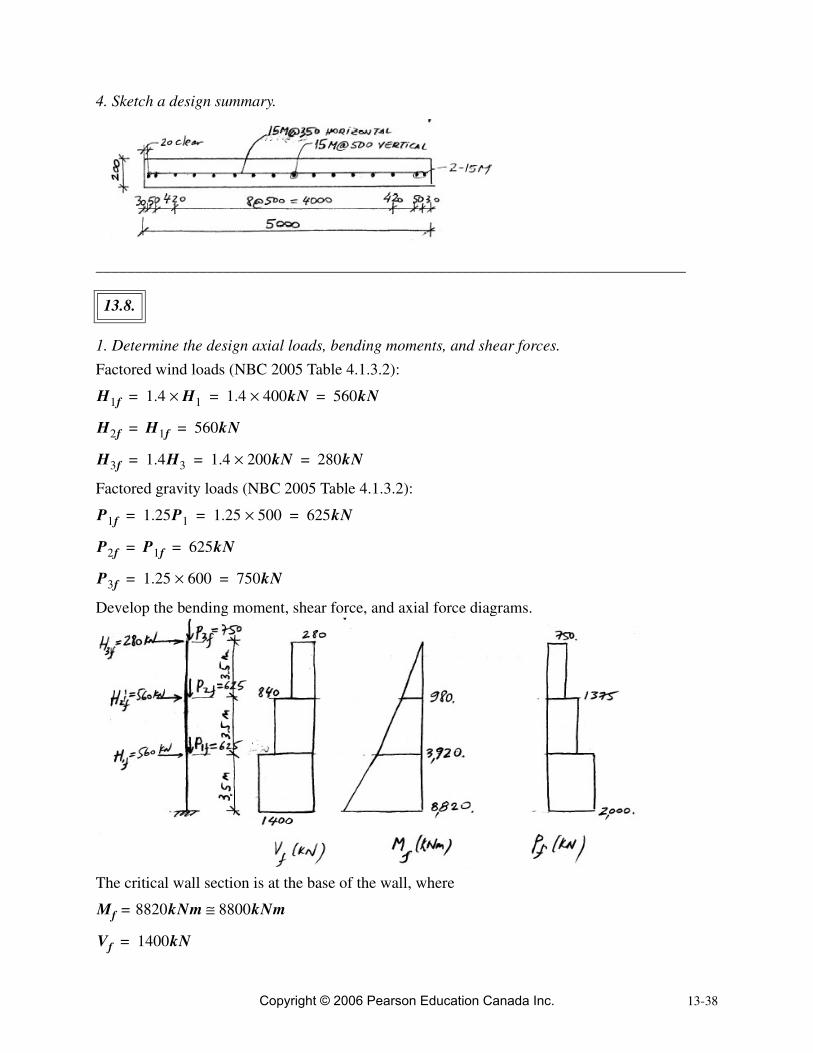
4. Sketch a design summary.
__________________________________________________________________________
1. Determine the design axial loads, bending moments, and shear forces.
Factored wind loads (NBC 2005 Table 4.1.3.2):
Factored gravity loads (NBC 2005 Table 4.1.3.2):
Develop the bending moment, shear force, and axial force diagrams.
The critical wall section is at the base of the wall, where
13.8.
H1f 1.4 H1× 1.4 400kN× 560kN= = =
H2f H1f 560kN= =
H3f 1.4H3 1.4 200kN× 280kN= = =
P1f 1.25P1 1.25 500× 625kN= = =
P2f P1f 625kN= =
P3f 1.25 600× 750kN= =
Mf 8820kNm= 8800kNm≅
Vf 1400kN=
Copyright © 2006 Pearson Education Canada Inc.

13-39
2. Design the wall for shear.
Design shear force:
Wall length:
Wall thickness:
The effective shear depth is
Find (A23.3 Cl.11.3.6.3), assuming a minimum shear reinforcement
Find .
(A23.3 Eq.11.6) [6.12]
Since
it follows that the shear reinforcement is required in this case.Find the required spacing of shear reinforcement
where
[6.9]
Use 10M bars in 2 layers (because the wall thickness is larger than 210 mm according to A23.3 Cl.14.1.8.3), hence
Find (A23.3 cl.11.3.6.3) as
The spacing of horizontal reinforcement can be determined from equation (6.9) as
Pf 2000kN=
Vf 1400kN=
lw 6000mm=
t 250mm=
dv( )
dv 0.8lw 0.8 6000mm× 4800mm= = =
β
β 0.18=
Vc
Vc φcλβ fc′tdv=
0.65 1.0 0.18 30MPa 250mm 4800mm×××× 769kN==
Vf 1400kN Vc 769kN=>=
Vs Vf Vc–≥ 1400 769– 631kN= =
VsφsAhfydv θcot
s----------------------------------=
Ah 2 100× 200mm2= =
θ
θ 35°= θcot 1.43=
sφsAhfydv θcot
s----------------------------------=
Copyright © 2006 Pearson Education Canada Inc.

13-40
Check whether the spacing is within the CSA A23.3 prescribed limits (Cl.14.1.8.4).
Since
Use
Horizontal reinforcement: 10M@500 (2 layers)In this design, two layers of reinforcement are required according to A23.3 Cl.14.1.8.3 (wall thickness larger than 210 mm).
3. Design the wall for flexure and axial load.
Design axial and flexural load effects:
• Determine the minimum vertical reinforcement (A23.3 Cl.14.1.8.5).
Assume
Determine the required bar spacing.
10M bars
Assume 2 layers of reinforcement, so
[3.29]
Check whether the bar spacing is within the limits prescribed by CSA A23.3 (Cl.14.1.8.4).
0.85 200mm2( )× 400MPa( ) 4800mm( )1.43
631 103N×------------------------------------------------------------------------------------------------------------ 740mm= =
smax3t 3 250 750mm =×=
500mm governs←���
≤
s 740mm smax> 500mm= =
s 500mm=
Pf 2000kN=
Mf 8800kNm=
Ag 1000mm t× 1000mm 250mm× 250 103mm2×= = =
Avmin 0.0015Ag=
0.0015 250 103mm2×( )× 375mm2 m⁄==
As Avmin 375mm2 m⁄= =
Area 100mm2, Table A.1=( )
Ab 2 100× 200mm2= =
s Ab1000
As------------ 200 1000
375------------× 533mm= =≤
smax3t 3 250 750mm =×=
500mm governs←���
≤
Copyright © 2006 Pearson Education Canada Inc.

13-41
Since
use
Vertical reinforcement: 10M@500 (2 layers)
• Determine the moment resistance .
i) Determine the total vertical reinforcement area along the wall length as
ii) Calculate the parameters , , and .
[3.7]
[13.9]
[13.10]
[13.8]
iii) Find the value.
[13.7]
Since
it follows that the moment resistance is not adequate (deficiency on the order of 15%).
s 533mm 500mm>=
s 500mm=
Mr( )
Avt( )
AsAbs
------ 1000× 200mm2
500mm--------------------- 1000× 400mm2 m⁄= = =
Avt As lw× 400mm2 m⁄( ) 6m( ) 2400mm2= = =
ω α clw----
α1 0.8≅ β1 0.9≅
ωφsfyAvtφcfc′lwt-------------------=
0.85 400MPa 2400mm2××0.65 30MPa 6000mm 250mm×××----------------------------------------------------------------------------------------- 0.028==
αPf
φcfc′lwt------------------- 2000 103N×
0.65 30MPa 6000mm 250mm×××----------------------------------------------------------------------------------------- 0.068= = =
clw---- ω α+
2ω α1 β1×+-------------------------------- 0.028 0.068+
2 0.028 0.8 0.9×+×-------------------------------------------------- 0.12= = =
Mr
Mr 0.5φsfyAvtlw 1Pf
φsfyAvt-----------------+� �
� � 1 clw----–� �
� �=
0.5 0.85 400MPa 2400mm2( )××× 6000mm( ) 1 2000 103N×0.85 400MPa 2400mm2××---------------------------------------------------------------------+
� �� � �
=
1 0.12–( ) 7434kNm=×
Mr 7434kNm Mf 8800kNm=<=
Copyright © 2006 Pearson Education Canada Inc.
13-42
Let us increase the amount of vertical reinforcement by decreasing the bar spacing to .
Use 2 layers of 10M@300 vertical rebars:
Recalculate , , and as follows
(same as before)
[13.8]
Since
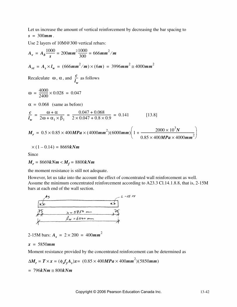
the moment resistance is still not adequate.However, let us take into the account the effect of concentrated wall reinforcement as well. Assume the minimum concentrated reinforcement according to A23.3 Cl.14.1.8.8, that is, 2-15M bars at each end of the wall section.
2-15M bars:
Moment resistance provided by the concentrated reinforcement can be determined as
s 300mm=
Av Ab1000
s------------ 200mm21000
300------------ 666mm2 m⁄= ==
Avt As lw× 666mm2 m⁄( ) 6m( )× 3996mm2 4000mm2≅= = =
ω α clw----
ω 40002400------------ 0.028× 0.047= =
α 0.068=
clw---- ω α+
2ω α1 β1×+-------------------------------- 0.047 0.068+
2 0.047 0.8 0.9×+×-------------------------------------------------- 0.141= = =
Mr 0.5 0.85 400MPa 4000mm2( )××× 6000mm( ) 1 2000 103N×0.85 400MPa 4000mm2××---------------------------------------------------------------------+
� �� � �
=
1 0.14–( ) 8669kNm=×
Mr 8669kNm= Mf 8800kNm=<
As 2 200× 400mm2= =
x 5850mm=
Mr T x× φsfyAs( )x 0.85 400MPa 400mm2××( ) 5850mm( )== =∆
796kNm 800kNm≅=
Copyright © 2006 Pearson Education Canada Inc.

13-43
The total wall moment resistance is
Since
it can be concluded that the total moment resistance provided by the distributed and concentrated wall reinforcement is adequate.
4. Sketch a design summary.
Mrtotal Mr Mr∆+ 8669 800+ 9469kNm= = =
Mrtotal 9469kNm Mf 8800kNm=>=
Copyright © 2006 Pearson Education Canada Inc.

13-44Copyright © 2006 Pearson Education Canada Inc.