brute iv extreme belt drive - rivera primo, incriveraprimoinc.com/brute-iv-extreme-for-dyna...step 6...
TRANSCRIPT

INSTALLATION INSTRUCTIONS FOR
BRUTE IV EXTREMETM
BELT DRIVEFOR 1990 TO 2005 EVO & TWIN CAM Dyna® Models
Shown w/optional mid-shift control
It’s common knowledge that a belt drive primary can provide advantages and service that a chain cannot, especially con-sidering the new technology present in every belt. For dependable,high performance, long-life service nothing beats amodern Primo Belt Drives primary-drivebelt-kit! Primo’s® long-time tradition of “Quality & Performance” has made our beltdrives the most popular in the world. That same quality & performance is now available in the Brute IV EXTREME™ 3”wide open electric-start primary belt-drive for most Softail®style motorcycles. The Brute IV EXTREME™ is ideal for street-performance, competition, and show-bike applications. Itlooks as good as it works. Carefully read and follow these instruc-tions for a quick, convenientinstallation. If you have any questions regarding this installation call (562) 907-2600 and aPRIMO BELT DRIVES technician will be happy to assist you!
Use of the word Harley-Davidson, various motorcycle model names & designations & OEM part numbers are for end-user reference or application informa¬tiononly. No affiliation between Rivera Engineering & The Harley-Davidson Motor Company exists or is implied by the use of said information. RiveraEngineering, Pro-Clutch, Primo, and Primo Belt Drives are registered trademarks of Rivera Engineering Inc & Primo Products Inc. Unauthorized use is pro¬hibited by law.
IMPORTANT SAFETY NOTE.... When performing any motorcycle work such as installing a belt drive it should be securely fastened inan upright positionwith easy access to the primary drive. If you are working with a lift, fasten the mo-torcycle securely to prevent it from falling.Always disconnect BOTH battery cables when performingthe following installation.
2108-0011 Rev. 3/15
PLEASE NOTE: PICTURES CONTAINED WITHIN THIS INSTRUCTION SHEET AREALSO USED FOR OTHER INSTRUCTIONS, SO THEY MAY NOT ACCURATELY DEPICT
THE BELT DRIVE THAT YOU HAVE PURCHASED.
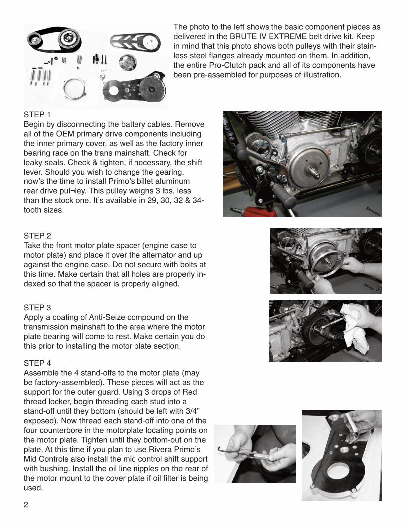
The photo to the left shows the basic component pieces asdelivered in the BRUTE IV EXTREME belt drive kit. Keepin mind that this photo shows both pulleys with their stain-less steel flanges already mounted on them. In addition,the entire Pro-Clutch pack and all of its components havebeen pre-assembled for purposes of illustration.
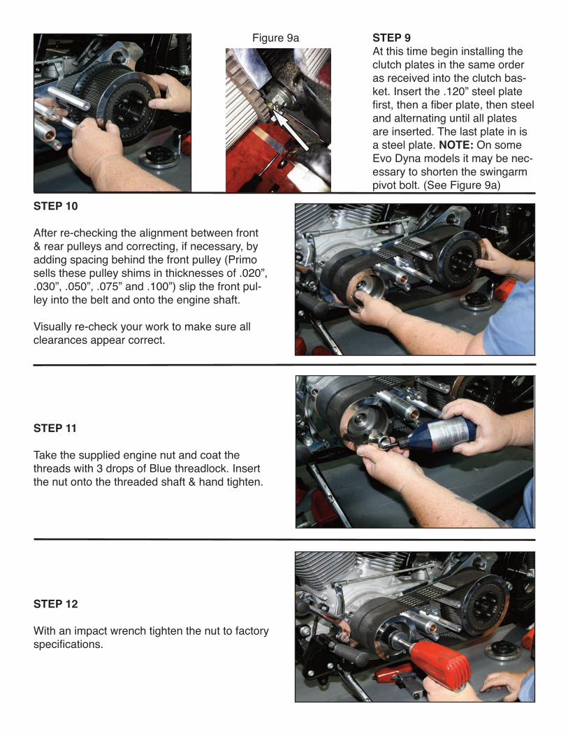
STEP 1 Begin by disconnecting the battery cables. Removeall of the OEM primary drive components includingthe inner primary cover, as well as the factory innerbearing race on the trans mainshaft. Check forleaky seals. Check & tighten, if necessary, the shiftlever. Should you wish to change the gearing,now’s the time to install Primo’s billet aluminumrear drive pul¬ley. This pulley weighs 3 lbs. lessthan the stock one. It’s available in 29, 30, 32 & 34-tooth sizes.
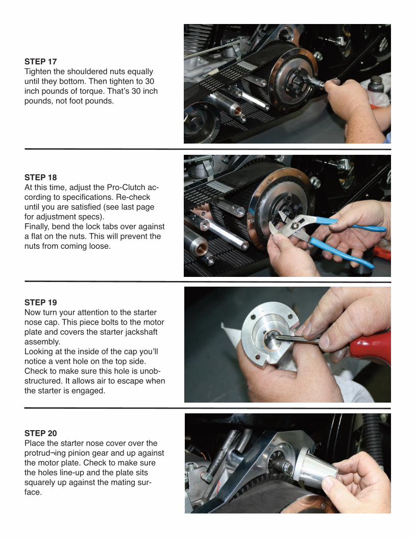
STEP 2 Take the front motor plate spacer (engine case tomotor plate) and place it over the alternator and upagainst the engine case. Do not secure with bolts atthis time. Make certain that all holes are properly in-dexed so that the spacer is properly aligned.
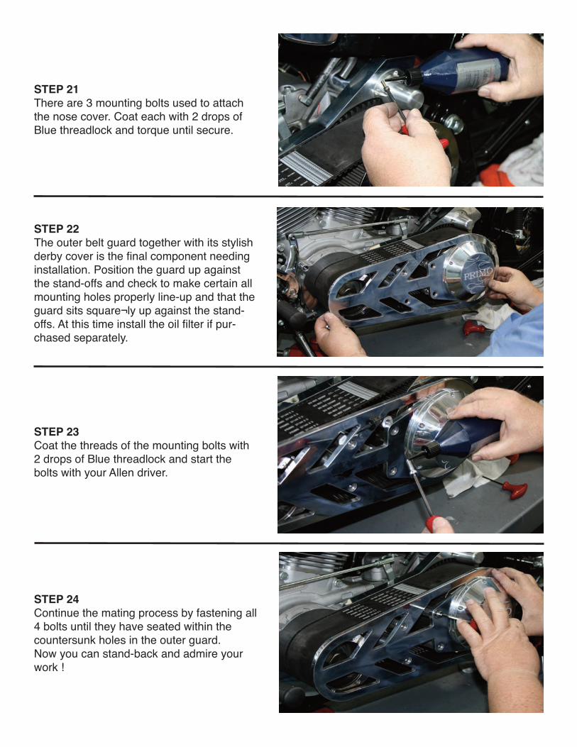
STEP 3 Apply a coating of Anti-Seize compound on thetransmission mainshaft to the area where the motorplate bearing will come to rest. Make certain you dothis prior to installing the motor plate section.
STEP 4 Assemble the 4 stand-offs to the motor plate (maybe factory-assembled). These pieces will act as thesupport for the outer guard. Using 3 drops of Redthread locker, begin threading each stud into astand-off until they bottom (should be left with 3/4”exposed). Now thread each stand-off into one of thefour counterbore in the motorplate locating points onthe motor plate. Tighten until they bottom-out on theplate. At this time if you plan to use Rivera Primo’sMid Controls also install the mid control shift supportwith bushing. Install the oil line nipples on the rear ofthe motor mount to the cover plate if oil filter is beingused.
2

STEP 6 Apply 3 drops of Blue threadlock to all seven mounting bolts. In-stall the 4 5/16 x 1.5” bolts in the front of the motorplate firstthreading each bolt in until they seat equally up against theplate. Check that even contact is made front-to-back on the mo-torplate rear surface. Proceed to tightening all 4 bolts equally.Now install the 3 eccentric cams into the rear of the motorplatenoting that the bottom cam is marked with a ‘B’. Align the camholes to the threaded holes in the transmission and then threadin the 3 5/16 x 2.250” bolts. This is what the mounted motorplate will look like to this point. Install oil filter nipple if center-mount oil filter is being used.
STEP 7 Install the starter motor using the two 5/16-18 x 3-3/4” socket head cap screws.Place the starter tothe rear of the trans flange and slide the bolts through to the threads in the motor plate.
STEP 8 At this point it’s time to address the starter jackshaft components which are included with the beltdrive kit (see last page for an exploded view of the starter mechanism).
STEP 5 Now it’s time to install the motor plate on the bike. Position theplate over the shafts and push forward until contact is made,sandwiching the front motor plate spacer between the motor plateand the engine case. Make certain all mounting holes are properlyindexed.
Begin by installing the starter coupler onto the end of the starter motor. Then the remaining pieces . . .the extender, spring, pinion gear, thrust washer, lockwasher and bolt. Insert this assembly into thecoupler. Make certain the lockwasher is correctly oriented to the slot in the extender. Tighten the bolt.Bend the locking tab over to keep the bolt from vibrating loose.
B
Note: The eccen-tric cams are usedon this belt drivebecause the boltpattern on the1990-2000 Dyna®models is differentthen the 2001-2005 Dyna® mod-els.
STEP 9At this time begin installing theclutch plates in the same orderas received into the clutch bas-ket. Insert the .120” steel platefirst, then a fiber plate, then steeland alternating until all platesare inserted. The last plate in isa steel plate. NOTE: On someEvo Dyna models it may be nec-essary to shorten the swingarmpivot bolt. (See Figure 9a)
STEP 10
After re-checking the alignment between front& rear pulleys and correcting, if necessary, byadding spacing behind the front pulley (Primosells these pulley shims in thicknesses of .020”,.030”, .050”, .075” and .100”) slip the front pul-ley into the belt and onto the engine shaft.
Visually re-check your work to make sure allclearances appear correct.
STEP 11
Take the supplied engine nut and coat thethreads with 3 drops of Blue threadlock. Insertthe nut onto the threaded shaft & hand tighten.
STEP 12
With an impact wrench tighten the nut to factoryspecifications.
Figure 9a

STEP 13Coat the threads of the transmissionmainshaft with 3 drops of Blue threadlock.Start the supplied clutch hub nut on theshaft & hand tighten (remember this is aleft-handed thread application). Finish thisprocedure with your impact wrench.Torque the clutch hub nut to factoryspecs, 70-90 foot pounds of torque. Thebelt should have no more than 1” total upand down free play and no less than 1/4”at the center of the belt.
STEP 14 Coat the threads of the Pro-Clutch studswith Anti-Seize compound. This will pre-vent the shouldered nuts from sticking tothe clutch hub stud threads during disas-sembly. Install the clutch adjusting screwinto the press¬ure plate. Insert the pres-sure plate (with the stamped “OUT” fac-ing out) into the rear pulley, up againstthe last steel plate previously installed inSTEP 8.
STEP 15 Prepare the diaphragm spring, the springretainer, lock tabs and shouldered nutsfor installation. Remember, the beveledside of the spring retainer faces in. In ad-dition, the retainer has a stamped “OUT”marking on it. This side should face out.
STEP 16 Install the diaphragm spring, makingsure the notches register correctly withthe now-in-place pressure plate. Follow this with the spring retainer(beveled side facing in), now assembledwith the locking tabs and the shoulderednuts.
STEP 17Tighten the shouldered nuts equallyuntil they bottom. Then tighten to 30inch pounds of torque. That’s 30 inchpounds, not foot pounds.
STEP 18 At this time, adjust the Pro-Clutch ac-cording to specifications. Re-checkuntil you are satisfied (see last pagefor adjustment specs). Finally, bend the lock tabs over againsta flat on the nuts. This will prevent thenuts from coming loose.
STEP 19 Now turn your attention to the starternose cap. This piece bolts to the motorplate and covers the starter jackshaftassembly. Looking at the inside of the cap you’llnotice a vent hole on the top side.Check to make sure this hole is unob-structured. It allows air to escape whenthe starter is engaged.
STEP 20 Place the starter nose cover over theprotrud¬ing pinion gear and up againstthe motor plate. Check to make surethe holes line-up and the plate sitssquarely up against the mating sur-face.
STEP 21There are 3 mounting bolts used to attachthe nose cover. Coat each with 2 drops ofBlue threadlock and torque until secure.
STEP 22The outer belt guard together with its stylishderby cover is the final component needinginstallation. Position the guard up againstthe stand-offs and check to make certain allmounting holes properly line-up and that theguard sits square¬ly up against the stand-offs. At this time install the oil filter if pur-chased separately.
STEP 23 Coat the threads of the mounting bolts with2 drops of Blue threadlock and start thebolts with your Allen driver.
STEP 24 Continue the mating process by fastening all4 bolts until they have seated within thecountersunk holes in the outer guard. Now you can stand-back and admire yourwork !

1-1/4-20 Bolt 2-10-32 Bolt3-lock tab4-thrust washer5-pinion gear6-spring7-extension shaft8-coupler
PRO CLUTCH ADJUSTMENT
BRUTE IV EXTREME CLUTCH PACK HEIGHT= 1.410” - 1.430”
As delivered the Pro-Clutch clutch-pack requires no adjustment, the clutch pack height having been set at the factory. AfterthePro-Clutch has accumulated significant mileage, it may require some adjustment due to normal wear. Use the proceduresout¬lined below if & when adjustment is required. For best all around performance the diaphragm spring should be com-pressed to with¬in .010” of being flat when the shouldered spring retainer nuts have been properly tightened (bottomed)! Thisprovides best leveraction at the handlebar, & normal spring pressure to the clutch pack. Slightly more clutch pressure can begained with the diaphragm spring with .030” of spring height (outward bow), but this increases slightly the hand effort neededfor the clutch. This spring con¬figuration can be obtained by placing a small diameter washer on each of the clutch hubstuds, as shown in photo B! Three clutch spring strengths are available: A stock equivalent spring (black in color), a mediumspring for street performance applications (silver in color), & a competition spring (gold in color) recommended for drag raceonly applications. If the diaphragm spring adjustment requires a smallamount of more spring compression, this can be ac-complished by using one or more of the special .020”washers on each odf the shouldered nuts (Photo A)
If the diaphragm spring adjustment requires lessf springcompression, this can be accomplished by using one ormore of the special .030” washers on on top of the clutchhub stud nuts reducing spring compression. (Photo B)
PHOTO A
Photo C shows a diaphragm spring that is compressedtoo far, & needs adjustment. Correct adjustment will re-quire that special adjustment washers be added to theclutch hub studs as shown in photo B.
PHOTO B
The diaphragm spring will be compressed to within .010”-to-.020” of flat when correctly installed & adjusted
This is a diaphragm spring correctly adjusted. Daylight isshowing at either edge, because the spring is within .010”of being flat! (Slightly bowed outward) as seen in photo D.
PHOTO C PHOTO D
12450 WHITTIER BLVD. WHITTIER, CA 90602
TEL: 562-907-2600 FAX: 562-907-2606
Orders: 800-872-1515
www.riveraprimoinc.com