brukermanualinlabsw4.0
DESCRIPTION
http://www.jacobsen-dental.no/filestore/PDF/CEREC/BrukermanualinLabSW4.0.pdfTRANSCRIPT
MPKOMNO
áåi~Ä=pt
kÉï=~ë=çÑW==
båÖäáëÜ
léÉê~íçêDë=j~åì~äpçÑíï~êÉ=sÉêëáçå=QKM
Operator's Manual\rSoftware version 4.0
Sirona Dental Systems GmbH Operator's Manual
Table of contents
1 Introduction............................................................................................................... 10
1.1 Dear Customer, ............................................................................................. 10
1.2 Copyright and trademark............................................................................... 10
2 General information.................................................................................................. 11
2.1 General safety information ............................................................................ 11
2.2 Structure of the manual................................................................................. 112.2.1 Identification of the danger levels....................................................... 112.2.2 Formats and symbols used................................................................ 122.2.3 Conventions ....................................................................................... 122.2.4 Formats of the manual ....................................................................... 122.2.5 Odontogram used .............................................................................. 132.2.6 File format .......................................................................................... 13
3 Getting started.......................................................................................................... 14
3.1 Installing the software ................................................................................... 14
3.2 Uninstalling the software ............................................................................... 14
3.3 Copy protection ............................................................................................. 15
3.4 Downloading the software............................................................................. 15
3.5 Starting the software ..................................................................................... 15
4 User interface ........................................................................................................... 16
4.1 Phase bar...................................................................................................... 174.1.1 ADMINISTRATION ............................................................................ 174.1.2 SCAN ................................................................................................. 174.1.3 MODEL .............................................................................................. 184.1.4 DESIGN ............................................................................................. 184.1.5 MILL ................................................................................................... 18
4.2 Object bar...................................................................................................... 18
4.3 Tool wheel ..................................................................................................... 19
4.4 Step menu..................................................................................................... 19
4.5 System menu ................................................................................................ 204.5.1 Save case .......................................................................................... 204.5.2 Save the case under a different name ............................................... 214.5.3 Import case ........................................................................................ 21
63 75 914 D35342 D3534.208.03.01.02 03.2012
Sirona Dental Systems GmbH Operator's Manual
båÖäáëÜ
4.5.4 Export case ....................................................................................... 214.5.5 License manager............................................................................... 214.5.6 Configuration..................................................................................... 224.5.7 Window mode ................................................................................... 224.5.8 Current program version ................................................................... 224.5.9 Closing the software.......................................................................... 22
4.6 Start window................................................................................................. 224.6.1 Creating a new order......................................................................... 234.6.2 Edit order data................................................................................... 234.6.2.1 Edit job order card ........................................................................... 234.6.2.2 Remove order.................................................................................. 244.6.2.3 Deleting a case................................................................................ 244.6.2.4 Opening a case ............................................................................... 244.6.2.5 Adding a new case .......................................................................... 24
5 Configuration ........................................................................................................... 25
5.1 Parameters................................................................................................... 25
5.2 Devices......................................................................................................... 325.2.1 inEos Blue ......................................................................................... 335.2.1.1 Resetting settings............................................................................ 335.2.1.2 Calibration ....................................................................................... 335.2.1.3 XYZ calibration ................................................................................ 345.2.2 CEREC Bluecam............................................................................... 345.2.2.1 Resetting settings............................................................................ 345.2.2.2 Calibration ....................................................................................... 345.2.3 Milling unit ......................................................................................... 355.2.3.1 Editing settings ................................................................................ 355.2.3.2 Calibration ....................................................................................... 365.2.3.3 Changing instruments ..................................................................... 365.2.3.4 Removing the milling unit ................................................................ 36
5.3 Options ......................................................................................................... 365.3.1 Odontogram ...................................................................................... 365.3.2 Check restoration parameters........................................................... 375.3.3 Reset notes ....................................................................................... 375.3.4 Database........................................................................................... 375.3.5 Calculating restorations..................................................................... 375.3.6 Auto-hide the page palette ................................................................ 38
6 Restoration types and design mode........................................................................ 39
63 75 914 D3534D3534.208.03.01.02 03.2012 3

Sirona Dental Systems GmbH Operator's Manual
6.1 Restoration types .......................................................................................... 39
6.2 Design mode ................................................................................................. 41
6.3 Biogeneric ..................................................................................................... 436.3.1 General information on Biogeneric..................................................... 436.3.2 Biogeneric Individual .......................................................................... 436.3.3 Biogeneric Copy................................................................................. 436.3.4 Biogeneric Reference......................................................................... 44
7 Edit orders ................................................................................................................ 45
7.1 Tools and functions of the page palette ........................................................ 457.1.1 Views.................................................................................................. 457.1.2 Tools .................................................................................................. 457.1.2.1 Buccal registration............................................................................ 467.1.2.2 Shaping ............................................................................................ 467.1.2.3 Cutting off model regions ................................................................. 477.1.2.4 Correcting defects ............................................................................ 487.1.2.5 Resetting changes ........................................................................... 487.1.2.6 Trimming .......................................................................................... 497.1.2.7 Entering the preparation margin....................................................... 497.1.2.8 Positioning........................................................................................ 507.1.2.9 Shaping ............................................................................................ 517.1.2.10Contacts ........................................................................................... 527.1.2.11Varying Biogeneric Morphology ....................................................... 527.1.2.12Adjusting the sprue position ............................................................. 527.1.2.13Moving the block .............................................................................. 537.1.2.14Reduce............................................................................................. 537.1.2.15Using a gingival mask ...................................................................... 537.1.2.16Dimension ........................................................................................ 547.1.2.17Scale ................................................................................................ 547.1.2.18Subtract Attachment from Pontic ..................................................... 557.1.2.19Tool wheel........................................................................................ 557.1.3 Displaying objects .............................................................................. 557.1.4 Analysis tools ..................................................................................... 58
7.2 ADMINISTRATION phase............................................................................. 60
7.3 ACQUISITION phase .................................................................................... 627.3.1 Camera view ...................................................................................... 627.3.2 inEos Blue.......................................................................................... 637.3.2.1 General ............................................................................................ 63
63 75 914 D35344 D3534.208.03.01.02 03.2012
Sirona Dental Systems GmbH Operator's Manual
båÖäáëÜ
7.3.2.2 Switching the inEos Blue on/off....................................................... 657.3.2.3 Grid scans ....................................................................................... 657.3.2.4 Free scans....................................................................................... 667.3.2.5 Rotational scans.............................................................................. 697.3.2.6 Acquiring a buccal registration ........................................................ 707.3.3 CEREC camera................................................................................. 707.3.3.1 Switching CEREC camera on/off .................................................... 707.3.3.2 Camera support............................................................................... 707.3.3.3 Preparing the optical impression ..................................................... 717.3.3.4 Acquire with the CEREC camera .................................................... 727.3.3.5 Supplementary optical impressions................................................. 737.3.3.6 Optical impressions for quadrant restoration................................... 747.3.3.7 Acquiring end teeth ......................................................................... 747.3.3.8 Acquiring an impression .................................................................. 747.3.4 3D Preview........................................................................................ 747.3.5 Image catalogs.................................................................................. 757.3.5.1 Working with the image catalog ...................................................... 767.3.5.2 Adding image catalogs .................................................................... 797.3.5.3 Recycle bin...................................................................................... 797.3.6 Finishing the phase ........................................................................... 80
7.4 MODEL phase.............................................................................................. 807.4.1 Editing the model .............................................................................. 807.4.2 Buccal registration............................................................................. 807.4.3 Set model axis................................................................................... 837.4.4 Trimming the preparation .................................................................. 837.4.5 Entering the preparation margin........................................................ 857.4.6 Defining the insertion axis ................................................................. 867.4.6.1 Preparing the right insertion axis..................................................... 877.4.6.2 Redefining the insertion axis ........................................................... 877.4.7 Finishing the phase ........................................................................... 87
7.5 Phase DESIGN ............................................................................................ 877.5.1 Adjusting parameters ........................................................................ 877.5.2 Editing the restoration ....................................................................... 877.5.3 Finishing the phase ........................................................................... 88
7.6 MILL phase................................................................................................... 887.6.1 Replacing the milling unit .................................................................. 887.6.2 Changing milling settings .................................................................. 887.6.3 Positioning the restoration in the block ............................................. 88
63 75 914 D3534D3534.208.03.01.02 03.2012 5
Sirona Dental Systems GmbH Operator's Manual
7.6.4 Exporting a restoration....................................................................... 897.6.5 Starting the milling procedure ............................................................ 89
8 Design examples...................................................................................................... 90
8.1 Abutment - Biogeneric individual - MultiLayer............................................... 908.1.1 Create a new restoration.................................................................... 908.1.2 Acquiring a preparation...................................................................... 908.1.3 Editing the model ............................................................................... 918.1.4 Bite registration .................................................................................. 918.1.5 Set model axis.................................................................................... 918.1.6 Mask areas......................................................................................... 918.1.7 Select Scanbody ................................................................................ 928.1.8 Define restoration axis ....................................................................... 928.1.9 Adjusting parameters ......................................................................... 938.1.10 Editing the restoration ........................................................................ 938.1.11 Grinding of restoration layers ............................................................. 93
8.2 Abutment - Biogeneric individual................................................................... 948.2.1 Create a new restoration.................................................................... 948.2.2 Acquiring a preparation...................................................................... 948.2.3 Editing the model ............................................................................... 948.2.4 Bite registration .................................................................................. 958.2.5 Set model axis.................................................................................... 958.2.6 Mask areas......................................................................................... 958.2.7 Select Scanbody ................................................................................ 958.2.8 Define restoration axis ....................................................................... 968.2.9 Adjusting parameters ......................................................................... 968.2.10 Editing the restoration ........................................................................ 978.2.11 Grinding the restoration...................................................................... 97
8.3 Abutment - FrameWork................................................................................. 978.3.1 Create a new restoration.................................................................... 978.3.2 Acquiring a preparation...................................................................... 988.3.3 Editing the model ............................................................................... 988.3.4 Bite registration .................................................................................. 988.3.5 Set model axis.................................................................................... 988.3.6 Mask areas......................................................................................... 998.3.7 Select Scanbody ................................................................................ 998.3.8 Define restoration axis ....................................................................... 1008.3.9 Adjusting parameters ......................................................................... 100
63 75 914 D35346 D3534.208.03.01.02 03.2012
Sirona Dental Systems GmbH Operator's Manual
båÖäáëÜ
8.3.10 Editing the restoration ....................................................................... 1008.3.11 Grinding the restoration..................................................................... 100
8.4 Bars .............................................................................................................. 1018.4.1 Create a new restoration................................................................... 1018.4.2 Acquiring a preparation ..................................................................... 1028.4.3 Editing the model .............................................................................. 1028.4.4 Bite registration ................................................................................. 1028.4.5 Set model axis................................................................................... 1028.4.6 Mask areas........................................................................................ 1038.4.7 Drawing the preparation margin........................................................ 1038.4.8 Defining axes .................................................................................... 1038.4.9 Adjusting parameters ........................................................................ 1048.4.10 Editing the restoration ....................................................................... 1058.4.11 Grinding the restoration..................................................................... 105
8.5 Attachments ................................................................................................. 1058.5.1 Create a new restoration................................................................... 1058.5.2 Acquiring a preparation ..................................................................... 1068.5.3 Editing the model .............................................................................. 1068.5.4 Bite registration ................................................................................. 1078.5.5 Set model axis................................................................................... 1078.5.6 Mask areas........................................................................................ 1078.5.7 Drawing the preparation margin........................................................ 1078.5.8 Defining axes .................................................................................... 1078.5.9 Adjusting parameters ........................................................................ 1088.5.10 Editing restorations ........................................................................... 1088.5.11 Grinding the restoration..................................................................... 109
8.6 Model............................................................................................................ 1108.6.1 Create a new restoration................................................................... 1108.6.2 Acquiring a preparation ..................................................................... 1108.6.3 Editing the model .............................................................................. 1118.6.4 Bite registration ................................................................................. 1118.6.5 Set model axis................................................................................... 1118.6.6 Editing restorations ........................................................................... 1118.6.7 Aligning the model............................................................................. 1128.6.8 Adjusting parameters ........................................................................ 1128.6.9 Segmentation .................................................................................... 1128.6.10 Undercutting segments ..................................................................... 1138.6.11 Placing pins....................................................................................... 114
63 75 914 D3534D3534.208.03.01.02 03.2012 7
Sirona Dental Systems GmbH Operator's Manual
8.6.12 Closing the model .............................................................................. 115
9 Tips and Tricks ......................................................................................................... 116
9.1 Service program............................................................................................ 116
9.2 Shortcut keys ................................................................................................ 117
10 inLab Stack SW 4.0.................................................................................................. 120
10.1 Getting started............................................................................................... 12010.1.1 Installing the software ........................................................................ 12010.1.2 Copy protection.................................................................................. 12010.1.3 Starting the software .......................................................................... 121
10.2 User interface................................................................................................ 12110.2.1 System menu ..................................................................................... 12110.2.1.1Saving a stack.................................................................................. 12210.2.1.2Importing a stack.............................................................................. 12210.2.1.3Exporting a stack.............................................................................. 12310.2.1.4Importing an element ....................................................................... 12310.2.1.5Exporting an element ....................................................................... 12310.2.1.6License manager.............................................................................. 12310.2.1.7Configuration.................................................................................... 12410.2.1.8Window mode .................................................................................. 12410.2.1.9Current program version .................................................................. 12410.2.1.10Closing the software....................................................................... 12410.2.2 Phase bar........................................................................................... 12410.2.3 Start window....................................................................................... 12510.2.3.1Creating a new stack........................................................................ 12510.2.3.2Opening a stack ............................................................................... 12510.2.3.3Removing a stack............................................................................. 12510.2.4 Step menu.......................................................................................... 125
10.3 Configuration................................................................................................. 12610.3.1 Parameters......................................................................................... 12610.3.2 Devices .............................................................................................. 12710.3.3 Options............................................................................................... 12710.3.3.1Odontogram ..................................................................................... 12810.3.3.2Reset notes ...................................................................................... 12810.3.3.3Legend proof .................................................................................... 12810.3.3.4Display legend.................................................................................. 12810.3.3.5Generate name automatically .......................................................... 128
63 75 914 D35348 D3534.208.03.01.02 03.2012
Sirona Dental Systems GmbH Operator's Manual
båÖäáëÜ
10.3.3.6Calculate stacks automatically ........................................................ 128
10.4 Edit orders .................................................................................................... 12910.4.1 COLLECT phase............................................................................... 12910.4.2 STACK phase ................................................................................... 12910.4.3 MILL phase ....................................................................................... 130
11 Sirona Connect portal.............................................................................................. 131
11.1 Starting the Sirona Connect portal ............................................................... 131
11.2 Log in to the portal........................................................................................ 131
11.3 Order list....................................................................................................... 131
11.4 Restoration data ........................................................................................... 131
11.5 Order information ......................................................................................... 131
11.6 Additional information................................................................................... 132
11.7 Displaying the order sheet............................................................................ 132
11.8 Checking the model...................................................................................... 132
11.9 Accepting/rejecting an order......................................................................... 133
11.10 Order list appears automatically................................................................... 133
Index........................................................................................................................ 134
63 75 914 D3534D3534.208.03.01.02 03.2012 9
63 75 914 D353410 D3534.208.03.01.02 03.2012
1 Introduction Sirona Dental Systems GmbH1.1 Dear Customer, Operator's Manual
1 IntroductionIntroduction
1.1 Dear Customer,Dear Customer,General description
Thank you for purchasing your inLab SW 4 software from Sirona.
In connection with inEos Blue / inLab MC XL, this software enables you to produce dental restorations, e.g. from ceramic material with a natural appearance (CEramic REConstruction).
Improper use and handling can create hazards and cause damage. Therefore, please read and carefully follow this manual and the relevant operating instructions. always keep them within easy reach.
In order to master the system safely, you should train on the exercise model using the described examples.
To prevent personal injury or material damage it is important to observe all safety information.
To safeguard your warranty claims, please complete the attached Installation Report / Warranty Passport when the system is handed over and send it to the indicated fax number.Your Team
Your inLab SW 4 Team
1.2 Copyright and trademarkCopyright and trademark
Copyright © Sirona Dental Systems GmbH 2011. Alle Rechte vorbehalten.
The information contained in this manual may be changed without notice.
The software and all related documentation are protected by copyright. You must therefore handle it in the same way as any other protected material.
Anyone who copies this software to any medium for any purpose other than his own personal use without the written permission of Sirona Dental Systems will be liable to prosecution.Trademarks
Trademarks Microsoft® and Windows 7® are registered trademarks.
WindowsTM is a trademark of Microsoft Corporation.
All other trademarks are the property of their respective holders.

Sirona Dental Systems GmbH 2 General informationOperator's Manual
båÖäáëÜ
2 General informationGeneral information
Please read this document completely and follow the instructions exactly. You should always keep it within reach.
Original language of the present document: German
2.1 General safety informationGeneral safety information
Only use original software
Only use original software or software which has been released by Sirona. To produce restorations, manipulated or non-released software components must not be used.
Software and software components must not be installed using incorrect data.
Please check that each installed component has been granted approval in its country. Contact your dealer for more information.For the USA only
For the USA only
CAUTION: According to US Federal Law, this product may be sold only to or by instruction of physicians, dentists, or licensed professionals.
2.2 Structure of the manualStructure of the manual
2.2.1 Identification of the danger levelsIdentification of the danger levels
To prevent personal injury and material damage, please observe the warning and safety information provided in this document. Such information is highlighted as follows:
Tip: Information on making work easier.
DANGERAn imminent danger that could result in serious bodily injury or death.
WARNINGA possibly dangerous situation that could result in serious bodily injury or death.
CAUTIONA possibly dangerous situation that could result in slight bodily injury.
NOTICE A possibly harmful situation which could lead to damage of the product or an object in its environment.
IMPORTANTApplication instructions and other important information.
63 75 914 D3534D3534.208.03.01.02 03.2012 11
2 General information Sirona Dental Systems GmbH2.2 Structure of the manual Operator's Manual
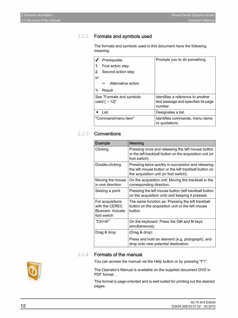
2.2.2 Formats and symbols usedFormats and symbols used
The formats and symbols used in this document have the following meaning:
2.2.3 ConventionsConventions
2.2.4 Formats of the manualFormats of the manualYou can access the manual via the Help button or by pressing "F1". PDF
The Operator's Manual is available on the supplied document DVD in PDF format. .
This format is page-oriented and is well suited for printing out the desired pages.
✔ Prerequisite1. First action step2. Second action stepor
➢ Alternative action
Result
Prompts you to do something.
See "Formats and symbols used [ → 12]“
Identifies a reference to another text passage and specifies its page number.
● List Designates a list."Command/menu item" Identifies commands, menu items
or quotations.
Example MeaningClicking Pressing once and releasing the left mouse button
or the left trackball button on the acquisition unit (or foot switch).
Double-clicking Pressing twice quickly in succession and releasing the left mouse button or the left trackball button on the acquisition unit (or foot switch).
Moving the mouse in one direction
On the acquisition unit: Moving the trackball in the corresponding direction.
Seizing a point Pressing the left mouse button (left trackball button on the acquisition unit) and keeping it pressed.
For acquisitions with the CEREC Bluecam: Actuate foot switch
The same function as: Pressing the left trackball button on the acquisition unit or the left mouse button.
"Ctrl+N" On the keyboard: Press the Ctrl and N keys simultaneously.
Drag & drop (Drag & drop)
Press and hold an element (e.g. pictograph), and drop onto new potential destination.
63 75 914 D353412 D3534.208.03.01.02 03.2012
Sirona Dental Systems GmbH 2 General informationOperator's Manual
båÖäáëÜ
2.2.5 Odontogram usedOdontogram used
The software can be adjusted to the international odontogram (FDI) or the USA odontogram (ADA) (Odontogram [ → 36]).
In this documentation teeth are named as follows:
2.2.6 File formatFile format
You can assign one or more orders to any dentist in the software. Depending on the processing status, an order comprises multiple optical impressions, the virtual models reconstructed from them and one or more virtual restorations.
The software uses its own file format (*.lab) to export an order. This format contains all of the order data. LAB files can be opened with other inLab software installations. Under certain circumstances, older software versions cannot open data exports from a more recent version.
Principle: FDI (#ADA)Example: 13 (#6)
63 75 914 D3534D3534.208.03.01.02 03.2012 13
3 Getting started Sirona Dental Systems GmbH3.1 Installing the software Operator's Manual
3 Getting startedGetting started
3.1 Installing the softwareInstalling the softwareAdministrator rights
✔ The PC is powered up and all programs are terminated.1. Insert the DVD into the DVD drive.
The setup program starts automatically.
2. If this is not the case, run the "Setup.exe" file in the root directory of the DVD.
The installation wizard opens.
3. Click on the "OK" button.4. In the next dialog box, click on the "Next" button.
The license agreement is shown.
5. Read through the license agreement carefully.6. If you accept the license agreement, then check the "I accept the
terms in the license agreement" option button and confirm your acceptance by clicking the "Next" button.
7. In the next dialog box, click on the "Next" button.8. In the next dialog box, click on the "Install" button.
The program continues the installation routine. This may take several minutes.
9. Following successful installation, click on the "Finish" button.The software is installed.
3.2 Uninstalling the softwareUninstalling the software
✔ The program is closed.1. Click on "Start / All Programs / Sirona Dental Systems / inLab /
Deinstallation" to uninstall the software.During the uninstall procedure, you will be asked whether you want to delete the patient data or the entries in the registration database (e.g. the calibration data).
2. Depending on your decision, click either "Yes" or "No".The software is uninstalled.
NOTICE Installation only with administrator rights
You must have administrator rights on the PC on which you want to install the software!
63 75 914 D353414 D3534.208.03.01.02 03.2012

Sirona Dental Systems GmbH 3 Getting startedOperator's Manual
båÖäáëÜ
3.3 Copy protectionCopy protectionUSB license stick inLab
The software can be started only when the USB license stick is plugged in. The USB license stick is included in the scope of supply of the units. If you require additional licenses, please contact your dealer.
Always keep the USB license stick near the unit.
All authorizations (milling, interface, software licenses) can be installed as electronic licenses on the USB license stick. You must enter a 25-digit license key for this purpose.You will receive the license key along with the unit. Alternatively, you can order it separately from your dealer.
Following an update, you may require a new license that is not available on your USB license stick. For more information, refer to the section on License manager [ → 21].
3.4 Downloading the softwareDownloading the software
New version
You can download the latest software version from the Sirona website www.sirona.com.Upgrade
Upgrade
Major software changes (upgrades) are subject to additional costs and require a new license. Without a new license, they only work in demo mode.
Contact your dealer to find out how to receive new licenses for an upgrade.
3.5 Starting the softwareStarting the software
✔ The inLab SW software is installed. You will find the start icon on the desktop.
✔ The USB license stick is connected with a valid, current license.➢ Double-click the inLab SW start icon.or
➢ Click on "Start / All Programs / Sirona Dental Systems/ inLab / inLab SW 4".
The software is started.
63 75 914 D3534D3534.208.03.01.02 03.2012 15
4 User interface Sirona Dental Systems GmbH Operator's Manual
4 User interfaceUser interface
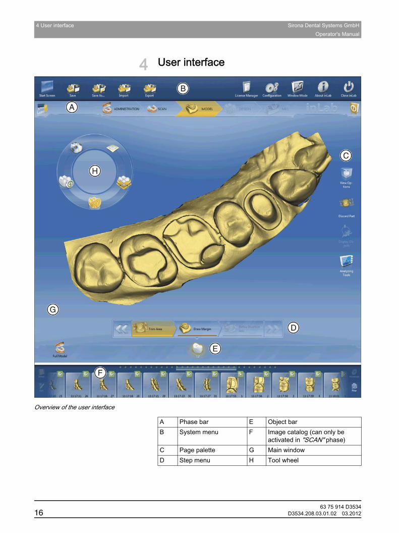
Overview of the user interface
A Phase bar E Object barB System menu F Image catalog (can only be
activated in "SCAN" phase)C Page palette G Main windowD Step menu H Tool wheel
63 75 914 D353416 D3534.208.03.01.02 03.2012

Sirona Dental Systems GmbH 4 User interfaceOperator's Manual
båÖäáëÜ
Bridge
4.1 Phase barPhase bar
The workflow is illustrated in the software in 5 phases.
Phase bar
● ADMINISTRATION
● SCAN
● MODEL
● DESIGN
● MILL
4.1.1 ADMINISTRATIONADMINISTRATIONIn this phase, you can perform the following:
● Create restorations and determine their type
● Define a milling unit
● Select material
4.1.2 SCANSCAN
In this phase, you can perform the following:inLab SW
● Acquisitions with inEos Blue - lower jaw, - upper jaw, - buccal bite registration
● View a 3D preview of the acquisitions
● Activate other image catalogs
If you have a CEREC license, you also can use the CEREC Bluecam.
I Detail display of bridge / multilayer
63 75 914 D3534D3534.208.03.01.02 03.2012 17
4 User interface Sirona Dental Systems GmbH4.2 Object bar Operator's Manual
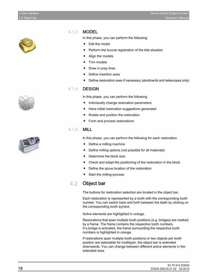
4.1.3 MODELMODELIn this phase, you can perform the following:
● Edit the model
● Perform the buccal registration of the bite situation
● Align the models
● Trim models
● Draw in prep lines
● Define insertion axes
● Define restoration axes if necessary (abutments and telescopes only)
4.1.4 DESIGNDESIGN
In this phase, you can perform the following:
● Individually change restoration parameters
● Have initial restoration suggestions generated
● Rotate and position the restoration
● Form and process restorations
4.1.5 MILLMILL
In this phase, you can perform the following for each restoration:
● Define a milling machine
● Define milling options (not possible for all materials)
● Determine the block size
● Check and adapt the positioning of the restoration in the block
● Define the sprue location of the restoration
● Start the milling process
4.2 Object barObject bar
The buttons for restoration selection are located in the object bar.
Each restoration is represented by a tooth with the corresponding tooth number. You can switch back and forth between the teeth by clicking on the corresponding tooth symbol.inLab bridges
Active elements are highlighted in orange.
Restorations that span multiple tooth positions (e.g. bridges) are marked by a frame. The frame contains the respective tooth numbers.If a bridge is activated, the frame surrounding the respective tooth numbers is highlighted in orange.
If restorations span multiple tooth positions or two objects per tooth position are selectable for multilayer, the object bar is extended downwards. You can change between different active elements in the extended area.
63 75 914 D353418 D3534.208.03.01.02 03.2012
Sirona Dental Systems GmbH 4 User interfaceOperator's Manual
båÖäáëÜ
4.3 Tool wheelTool wheelDescription of CEREC SW 4
The tool wheel makes the standard tools available in the MODEL and DESIGN phases in order to simplify access. The tools currently available vary depending on the current step.
1. Right-click in the workspace.The tool wheel opens.
2. Click with the right mouse button anywhere in the workspace.The tool wheel moves to the position of the mouse pointer.
3. Select a tool.The selected tool is available. The tool wheel closes automatically.
You also can close the tool by clicking in the workspace with the left mouse button.
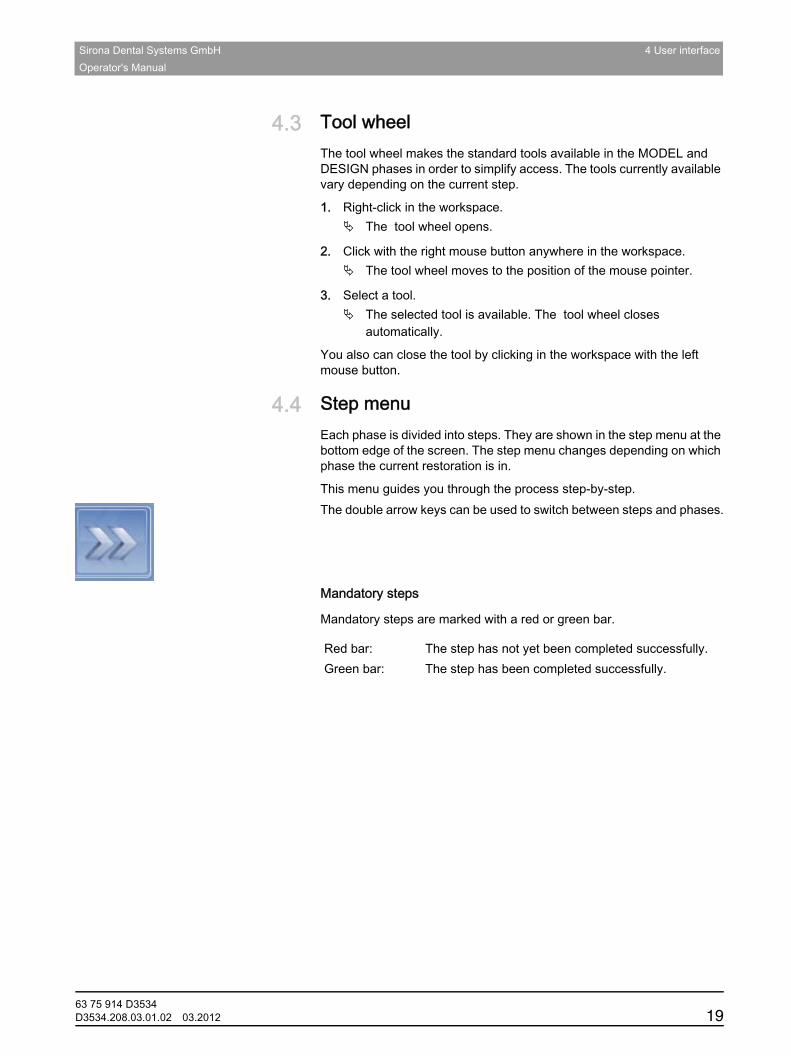
4.4 Step menuStep menuGeneral description
Each phase is divided into steps. They are shown in the step menu at the bottom edge of the screen. The step menu changes depending on which phase the current restoration is in.
This menu guides you through the process step-by-step.Double arrow keysThe double arrow keys can be used to switch between steps and phases.Mandatory steps
Mandatory steps
Mandatory steps are marked with a red or green bar.
Red bar: The step has not yet been completed successfully.Green bar: The step has been completed successfully.
63 75 914 D3534D3534.208.03.01.02 03.2012 19
4 User interface Sirona Dental Systems GmbH4.5 System menu Operator's Manual
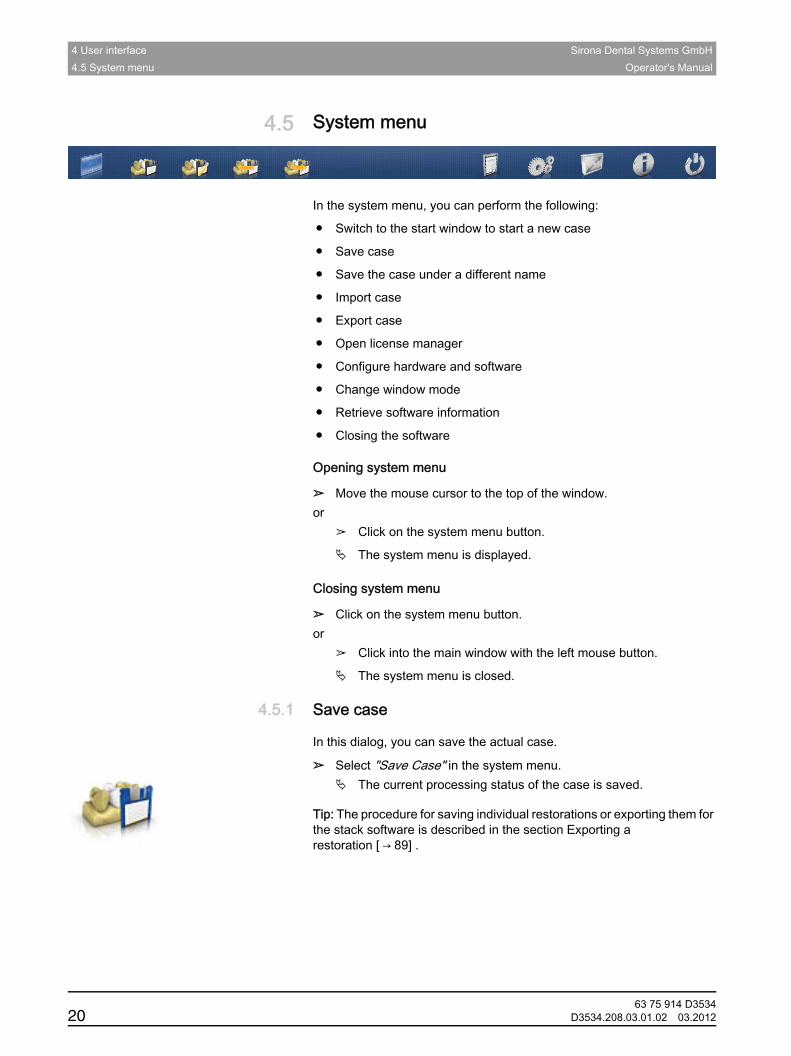
4.5 System menuSystem menu
In the system menu, you can perform the following:
● Switch to the start window to start a new case
● Save case
● Save the case under a different name
● Import case
● Export case
● Open license manager
● Configure hardware and software
● Change window mode
● Retrieve software information
● Closing the softwareOpening the system menu
Opening system menu
➢ Move the mouse cursor to the top of the window.or
➢ Click on the system menu button.
The system menu is displayed.Closing the system menu
Closing system menu
➢ Click on the system menu button.or
➢ Click into the main window with the left mouse button.
The system menu is closed.
4.5.1 Save caseSave case
In this dialog, you can save the actual case.
➢ Select "Save Case" in the system menu.The current processing status of the case is saved.
Save restorations or export them for the stack software
Tip: The procedure for saving individual restorations or exporting them for the stack software is described in the section Exporting a restoration [ → 89] .
63 75 914 D353420 D3534.208.03.01.02 03.2012
Sirona Dental Systems GmbH 4 User interfaceOperator's Manual
båÖäáëÜ
4.5.2 Save the case under a different nameSave the case under a different name
This dialog allows you to save the current case under a new name or assign it to a different patient.
1. Select "Save Case As..." in the system menu.The patient list is opened.
2. Select the appropriate patient.or
➢ Create a new patient via "Add New Patient".
4.5.3 Import caseImport case
✔ The LAB file (or older CDT file) is stored on the inLab 4 PC or on a storage medium connected to it.
1. Click the "Import Case..." button in the system menu.The "Import Case..." dialog box opens.
2. Select the folder where the case is located. 3. Select the relevant file.4. Click the "Open" button
The case is then imported and opened.Depending on the type of restoration, only the optical impression is opened.
4.5.4 Export caseExport caseExporting
You can store a case in any location.
✔ You have opened a case in the software.1. Click the "Export Case..." button in the system menu.
The "Export Case..." dialog box opens.
2. Select the target folder to which you want to export the case.3. Assign any name to the case.4. Click on the "Save" button.
The case is exported as an LAB file.Transfer
If you would like to transfer the optical impression to another PC, you can use a USB stick or a network drive for this purpose.
4.5.5 License managerLicense managerThe license manager is used for the installation of new software licenses on the USB license stick. To do this, start the license manager via the system menu and follow the instructions on the screen. Keep the license certificate with 25-digit license key ready, which you either obtained with the unit or ordered separately from your dealer.
To activate the license you must have an Internet connection and the USB license stick must be connected.
63 75 914 D3534D3534.208.03.01.02 03.2012 21
4 User interface Sirona Dental Systems GmbH4.6 Start window Operator's Manual
4.5.6 ConfigurationConfigurationThe configuration is described in the chapter "Configuration [ → 25]".
4.5.7 Window modeWindow mode
The "Window Mode" function can be used to exit full-screen mode or enter it again.
4.5.8 Current program versionCurrent program version
CEREC SW 4
The "About" function contains information about the current program version.
4.5.9 Closing the softwareClosing the software
Closing CEREC SW 4
The "Exit" function can be used to close the software.
4.6 Start windowStart windowinLab SW 4 start window options
In the start window, you can perform the following:
● Create or select an order
● Edit order data
● Search for an order
● Open cases
● Delete cases
● Add casesSwitching to the start window
63 75 914 D353422 D3534.208.03.01.02 03.2012
Sirona Dental Systems GmbH 4 User interfaceOperator's Manual
båÖäáëÜ
Switching to the start view
You can switch to the start view at any time.
1. Open the system menu.2. Click on the "Start Screen" button.
4.6.1 Creating a new orderCreating a new order
In the data structure, orders are uniquely identified by one of the following two entries:
● Name of the dentist and name of the patient or
● Name of the dentist and order number
Add order
1. If the dentist concerned has already been created, click on the dentist.
2. Click on the"Add New Order"button.A job order card opens. The name of the dentist that you preselected is then suggested.
3. Enter the name of the dentist and the name of the patient.or
➢ Enter the name of the dentist and the order number.
Once you have entered enough information, the bar in the"Edit Order"step turns from red to green.
4. Click on the"Add New Case"button.The program switches over to the"ADMINISTRATION"phase.
4.6.2 Edit order dataEdit order data
4.6.2.1 Edit job order cardEdit job order card✔ You have found the order in the overview.1. Click the job order card.2. Click on the "Edit Order" step in the step menu.
The job order card is opened for editing.
3. Carry out the changes.4. Confirm your changes by clicking the "Ok" button.
The changes are saved in the memory.
5. Click the double arrow on the left side of the step menu.The overview is displayed.
63 75 914 D3534D3534.208.03.01.02 03.2012 23
4 User interface Sirona Dental Systems GmbH4.6 Start window Operator's Manual
4.6.2.2 Remove orderRemove order
✔ You have found the order in the overview.1. Click on the case you would like to remove.2. Click on the "Delete Order" step in the step menu.3. Confirm the deletion by clicking the "Ok" button.
The order is deleted.
4.6.2.3 Deleting a caseDeleting a caseinLab SW
✔ You have found the associated order in the overview.1. Click on the order.2. Select the case.3. Click on the "Delete Case" step in the step menu.4. Confirm the deletion by clicking the "Ok" button.
The case is deleted.
4.6.2.4 Opening a caseOpening a caseinLab SW
✔ You have found the associated order in the overview.1. Click on the order.2. Select the case.3. Click on the "Open Case" step in the step menu.
The restoration is opened.
4.6.2.5 Adding a new caseAdding a new caseinLab SW
✔ You have found the associated order in the overview.1. Click on the order.2. Click on the "Add New Case" step in the step menu.
The program switches over to the "ADMINISTRATION" phase.
63 75 914 D353424 D3534.208.03.01.02 03.2012

Sirona Dental Systems GmbH 5 ConfigurationOperator's Manual
båÖäáëÜ
5 ConfigurationConfigurationThe "Configuration" menu contains three sub-menus:
● Parameters
● Devices
● Options
5.1 ParametersParametersThe "Parameters" menu is structured by restoration type. You can make the settings for each of the following restoration types.
The changes in the values are displayed graphically.
Changed parameter settings are accepted for all initial suggestions here.Tip
Tip: If you want to change the parameter values only for one restoration, do this in the DESIGN phase in the step "Restoration Parameters".Crown, inlay, veneer parameters
Crown, inlay, onlay and veneer
Parameters Description Default valueCrown Inlay/
OnlayVeneer
Spacer ● Possibility for setting the space for the fastening material below the restoration. Acts up to the preparation margin.
80µm 80µm 80µm
Marginal Adhesive Gap ● Adjust width of space on preparation margin.
● The value of the adhesive gap cannot exceed the spacer value.
- 60µm -
Veneer Thickness ● Set to minimum thickness.
● The software tries not to fall below this thickness when calculating the restoration suggestions.
● DESIGNandMILLphases: The value is displayed as a semitransparent geometry on the preparation. Areas where the thickness falls short of the minimum level in the design phase are thus made visible.
- - 500µm
Occlusal Milling Offset ● Apply or remove material in the occlusal direction over the entire occlusal surface.
● This value concerns only the milling result.
● DESIGNandMILLphases: The effects are not visible.
0µm 0µm 0µm
Proximal Contacts Strength ● Set the thickness of the approximal contacts.
● The software tries to achieve this stored thickness in the restoration suggestions.
25µm 2µm -
Occlusal Contacts Strength ● Set the thickness of the occlusal contacts.
● The software tries to achieve this stored thickness in the restoration suggestions.
25µm 2µm -
63 75 914 D3534D3534.208.03.01.02 03.2012 25
5 Configuration Sirona Dental Systems GmbH5.1 Parameters Operator's Manual
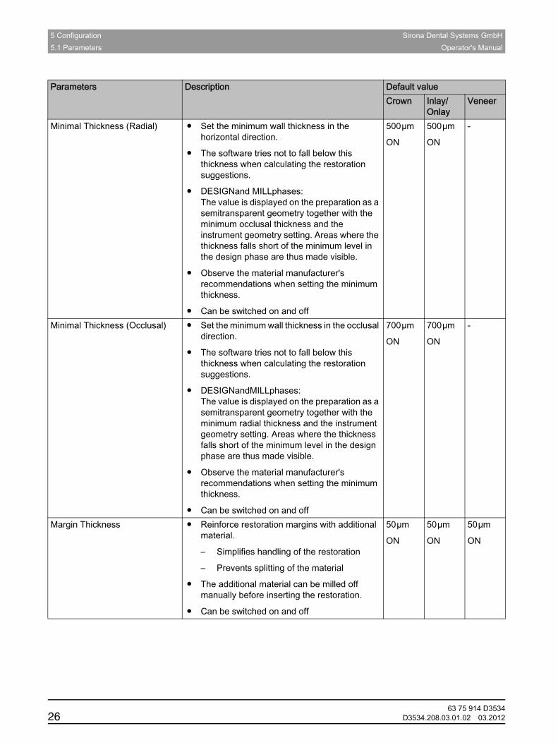
Minimal Thickness (Radial) ● Set the minimum wall thickness in the horizontal direction.
● The software tries not to fall below this thickness when calculating the restoration suggestions.
● DESIGNand MILLphases: The value is displayed on the preparation as a semitransparent geometry together with the minimum occlusal thickness and the instrument geometry setting. Areas where the thickness falls short of the minimum level in the design phase are thus made visible.
● Observe the material manufacturer's recommendations when setting the minimum thickness.
● Can be switched on and off
500µm
ON
500µm
ON
-
Minimal Thickness (Occlusal) ● Set the minimum wall thickness in the occlusal direction.
● The software tries not to fall below this thickness when calculating the restoration suggestions.
● DESIGNandMILLphases: The value is displayed on the preparation as a semitransparent geometry together with the minimum radial thickness and the instrument geometry setting. Areas where the thickness falls short of the minimum level in the design phase are thus made visible.
● Observe the material manufacturer's recommendations when setting the minimum thickness.
● Can be switched on and off
700µm
ON
700µm
ON
-
Margin Thickness ● Reinforce restoration margins with additional material.
– Simplifies handling of the restoration
– Prevents splitting of the material
● The additional material can be milled off manually before inserting the restoration.
● Can be switched on and off
50µm
ON
50µm
ON
50µm
ON
Parameters Description Default valueCrown Inlay/
OnlayVeneer
63 75 914 D353426 D3534.208.03.01.02 03.2012
Sirona Dental Systems GmbH 5 ConfigurationOperator's Manual
båÖäáëÜ
Abutment parameters (anatomic, framework, bottom layer)
Abutment (anatomical, framework, lower layer)
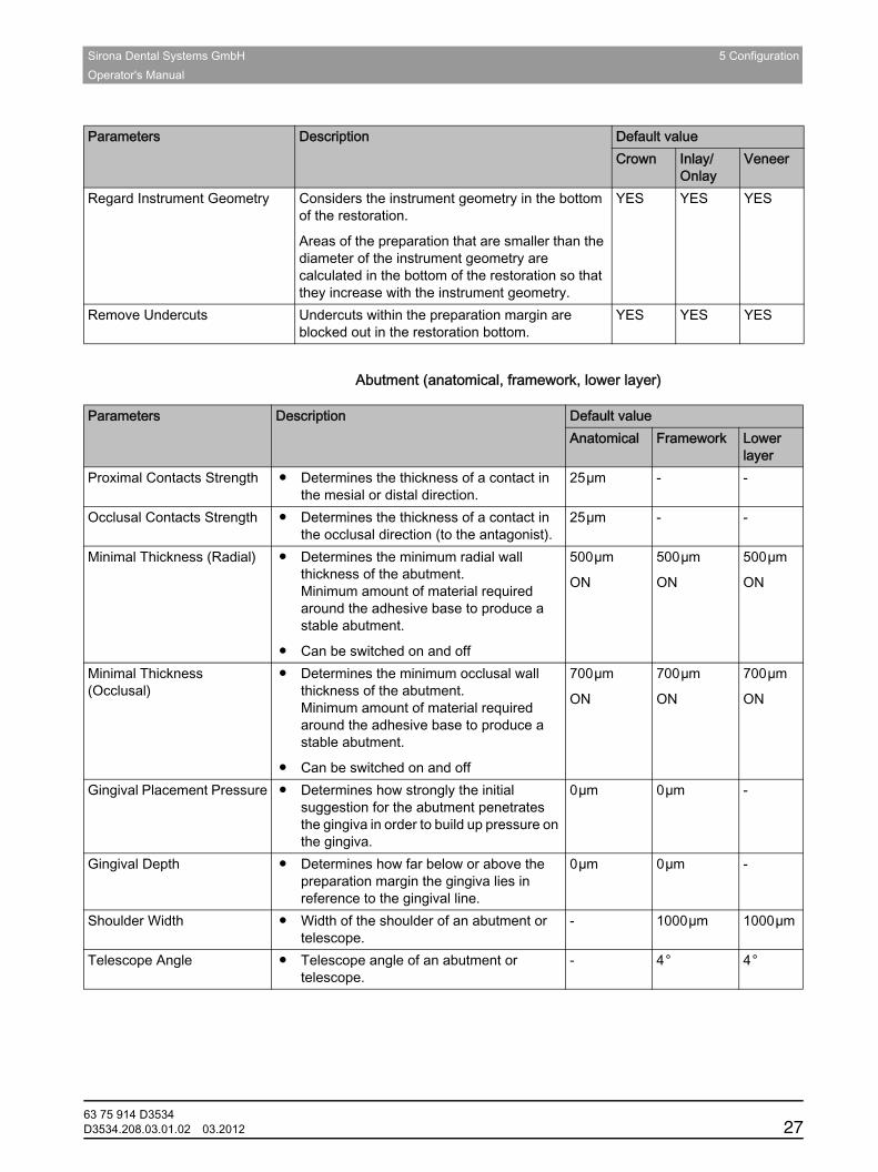
Regard Instrument Geometry Considers the instrument geometry in the bottom of the restoration.
Areas of the preparation that are smaller than the diameter of the instrument geometry are calculated in the bottom of the restoration so that they increase with the instrument geometry.
YES YES YES
Remove Undercuts Undercuts within the preparation margin are blocked out in the restoration bottom.
YES YES YES
Parameters Description Default valueCrown Inlay/
OnlayVeneer
Parameters Description Default valueAnatomical Framework Lower
layerProximal Contacts Strength ● Determines the thickness of a contact in
the mesial or distal direction.25µm - -
Occlusal Contacts Strength ● Determines the thickness of a contact in the occlusal direction (to the antagonist).
25µm - -
Minimal Thickness (Radial) ● Determines the minimum radial wall thickness of the abutment.Minimum amount of material required around the adhesive base to produce a stable abutment.
● Can be switched on and off
500µm
ON
500µm
ON
500µm
ON
Minimal Thickness (Occlusal)
● Determines the minimum occlusal wall thickness of the abutment.Minimum amount of material required around the adhesive base to produce a stable abutment.
● Can be switched on and off
700µm
ON
700µm
ON
700µm
ON
Gingival Placement Pressure ● Determines how strongly the initial suggestion for the abutment penetrates the gingiva in order to build up pressure on the gingiva.
0µm 0µm -
Gingival Depth ● Determines how far below or above the preparation margin the gingiva lies in reference to the gingival line.
0µm 0µm -
Shoulder Width ● Width of the shoulder of an abutment or telescope.
- 1000µm 1000µm
Telescope Angle ● Telescope angle of an abutment or telescope.
- 4° 4°
63 75 914 D3534D3534.208.03.01.02 03.2012 27

5 Configuration Sirona Dental Systems GmbH5.1 Parameters Operator's Manual
Crown parameters (framework, telescope)
Crown (framework, telescope)
Parameters Description Default valueFramework Telescope
Spacer ● Possibility for setting the space for the fastening material below the restoration. Acts up to the preparation margin.
80µm 80µm
Minimal Thickness (Radial) ● Set the minimum wall thickness in the horizontal direction.
● The value determines the radial wall thickness of the crown cap.
● DESIGN and MILL phases:The value is displayed on the preparation as a semitransparent geometry together with the minimum occlusal thickness and the instrument geometry setting. Areas where the thickness falls short of the minimum level in the design phase are thus made visible.
● Can be switched on and off
500µm
ON
500µm
ON
Minimal Thickness (Occlusal) ● Set the minimum wall thickness in the occlusal direction.
● The value determines the occlusal wall thickness of the crown cap.
● DESIGN and MILL phases:The value is displayed on the preparation as a semitransparent geometry together with the minimum radial thickness and the instrument geometry setting. Areas where the thickness falls short of the minimum level in the design phase are thus made visible.
● Can be switched on and off
700µm
ON
700µm
ON
Margin Thickness ● Reinforce restoration margins with additional material.
– Simplifies handling of the restoration
– Prevents splitting of the material
● The additional material can be milled off manually before inserting the restoration.
● Can be switched on and off
50µm
ON
50µm
ON
Telescope Angle ● Angle by which the outer wall of the telescope cone is inclined inward in relation to the restoration axis.
- 4°
Telescope Height ● Initial height of the outer wall of the telescope cone from the cervical shoulder to the junction to the occlusal surface.
● It influences the size of the friction surface.
- 3000µm
63 75 914 D353428 D3534.208.03.01.02 03.2012

Sirona Dental Systems GmbH 5 ConfigurationOperator's Manual
båÖäáëÜ
Attachment parameters
Attachment
Bar parameters
Bar
Occlusal Shoulder Width ● Width of the occlusal shoulder at the junction between the outer wall of the telescope cone and the occlusal surface.
● The occlusal shoulder is inclined inward 45° in relation to the telescope axis.
- 300µm
Regard Instrument Geometry ● Considers the instrument geometry in the bottom of the restoration.
● Areas of the preparation that are smaller than the diameter of the instrument geometry are calculated in the bottom of the restoration so that they increase with the instrument geometry.
YES YES
Remove Undercuts ● Undercuts within the preparation margin are blocked out in the restoration bottom.
YES YES
Parameters Description Default valueFramework Telescope
Parameters Description Default valueAttachment Diameter ● Diameter of the cylindrical anchor of the
positive part.1500
Attachment Height ● Height of the entire positive part. 2000Attachment Bridge Length ● Length of male bridge.
The male bridge is the connecting element between the anchor and the base.
1000
Attachment Bridge Width ● Width of bridge. 1000Attachment Gingiva Distance ● Distance from male bottom to gingival
adaptation.
● Negative values result in a penetration of the gingiva.
0
Attachment Gingiva Adaption ● Gingival adaptation: yes / no YESAttachment Shoulder ● Plate over the gingiva: yes / no YESAttachment Spacer Value ● Divided attachment:
Space between positive part and cut-out negative part in neighboring positive part.
80µm
Attachment Shoulder Width ● Size of plate located on the gingiva. 500µm
Parameters Description Default valueBar Height ● Describes the height of the bar segment in µm. 3000Bar Width ● Describes the width of the bar segment in µm. 3000Bar Cone Angle ● Describes the angle of incidence of lateral and
friction surfaces in degrees.
● Applies only to primary bars (design mode squared).
4°
63 75 914 D3534D3534.208.03.01.02 03.2012 29
5 Configuration Sirona Dental Systems GmbH5.1 Parameters Operator's Manual
Pontic parameters (anatomic)
Pontic (anatomical, framework)
Multilayer crown parameters (bottom layer)
Crown (bottom layer)
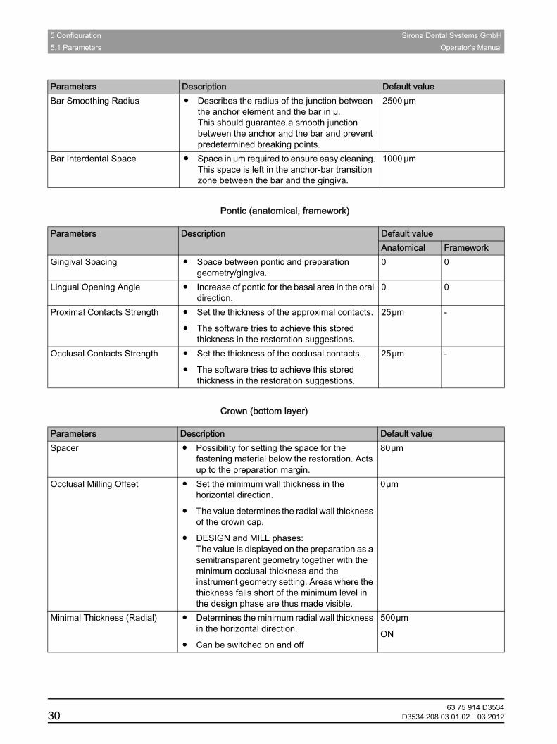
Bar Smoothing Radius ● Describes the radius of the junction between the anchor element and the bar in µ.This should guarantee a smooth junction between the anchor and the bar and prevent predetermined breaking points.
2500 µm
Bar Interdental Space ● Space in µm required to ensure easy cleaning. This space is left in the anchor-bar transition zone between the bar and the gingiva.
1000 µm
Parameters Description Default value
Parameters Description Default valueAnatomical Framework
Gingival Spacing ● Space between pontic and preparation geometry/gingiva.
0 0
Lingual Opening Angle ● Increase of pontic for the basal area in the oral direction.
0 0
Proximal Contacts Strength ● Set the thickness of the approximal contacts.
● The software tries to achieve this stored thickness in the restoration suggestions.
25µm -
Occlusal Contacts Strength ● Set the thickness of the occlusal contacts.
● The software tries to achieve this stored thickness in the restoration suggestions.
25µm -
Parameters Description Default valueSpacer ● Possibility for setting the space for the
fastening material below the restoration. Acts up to the preparation margin.
80µm
Occlusal Milling Offset ● Set the minimum wall thickness in the horizontal direction.
● The value determines the radial wall thickness of the crown cap.
● DESIGN and MILL phases:The value is displayed on the preparation as a semitransparent geometry together with the minimum occlusal thickness and the instrument geometry setting. Areas where the thickness falls short of the minimum level in the design phase are thus made visible.
0µm
Minimal Thickness (Radial) ● Determines the minimum radial wall thickness in the horizontal direction.
● Can be switched on and off
500µm
ON
63 75 914 D353430 D3534.208.03.01.02 03.2012
Sirona Dental Systems GmbH 5 ConfigurationOperator's Manual
båÖäáëÜ
Multilayer crown parameters (top layer)
Crown (top layer)
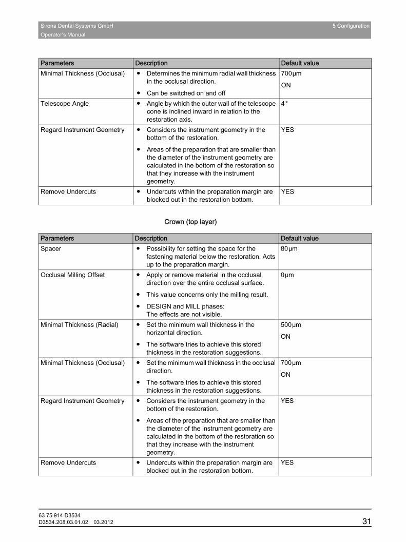
Minimal Thickness (Occlusal) ● Determines the minimum radial wall thickness in the occlusal direction.
● Can be switched on and off
700µm
ON
Telescope Angle ● Angle by which the outer wall of the telescope cone is inclined inward in relation to the restoration axis.
4°
Regard Instrument Geometry ● Considers the instrument geometry in the bottom of the restoration.
● Areas of the preparation that are smaller than the diameter of the instrument geometry are calculated in the bottom of the restoration so that they increase with the instrument geometry.
YES
Remove Undercuts ● Undercuts within the preparation margin are blocked out in the restoration bottom.
YES
Parameters Description Default value
Parameters Description Default valueSpacer ● Possibility for setting the space for the
fastening material below the restoration. Acts up to the preparation margin.
80µm
Occlusal Milling Offset ● Apply or remove material in the occlusal direction over the entire occlusal surface.
● This value concerns only the milling result.
● DESIGN and MILL phases:The effects are not visible.
0µm
Minimal Thickness (Radial) ● Set the minimum wall thickness in the horizontal direction.
● The software tries to achieve this stored thickness in the restoration suggestions.
500µm
ON
Minimal Thickness (Occlusal) ● Set the minimum wall thickness in the occlusal direction.
● The software tries to achieve this stored thickness in the restoration suggestions.
700µm
ON
Regard Instrument Geometry ● Considers the instrument geometry in the bottom of the restoration.
● Areas of the preparation that are smaller than the diameter of the instrument geometry are calculated in the bottom of the restoration so that they increase with the instrument geometry.
YES
Remove Undercuts ● Undercuts within the preparation margin are blocked out in the restoration bottom.
YES
63 75 914 D3534D3534.208.03.01.02 03.2012 31
5 Configuration Sirona Dental Systems GmbH5.2 Devices Operator's Manual
Model
Model
Observe the information supplied concerning the pins, model holders and base plates.
Applying/discarding settings
Accepting settings
➢ Click on the "Ok" button.
Discarding settings
➢ Click on the "Cancel" button.Resetting settings
Resetting settings
➢ Click on the "Reset All Group Parameter" button.The settings for this restoration type are reset to the factory settings.
5.2 DevicesDevicesAll connected devices can be displayed and configured under the menu item "Devices".A green check mark on a device indicates its availability.Adding devices (automatically)
Adding devices automatically
You can add additional devices with the "Scan for New Devices" function.
✔ The device is attached to the PC.1. Click on the "Scan for New Devices" button.
All devices attached to the PC are detected. You will be prompted to enter a name for new devices.
2. Enter a name for the new device.Adding devices (manually)
Parameters DescriptionSegmentation Cut Width ● Set the width of the saw-cut.Baseplate Distance ● Adjust the distance of the base plates from each other.Pin Diameter ● Set the diameter of the pins.Pin Spacing ● Set the distance of the pins from each other.
63 75 914 D353432 D3534.208.03.01.02 03.2012
Sirona Dental Systems GmbH 5 ConfigurationOperator's Manual
båÖäáëÜ
Adding devices (manually)
You can manually add devices with the "Add Device (Manual)" function. This is mandatory for devices which cannot be operated at the maximum speed of 115,200 baud. This applies to devices with long cable connections or certain radio modules (e.g. Futaba, 19200 baud).
1. Click on the "Add Device (Manual)" button.2. Select whether the device is connected to the network or in series.3. Network: Enter the network address.
In series: Enter the COM port and the baud rate.4. Click on the "Ok" button.
The software attempts to contact the device.
If the connection fails, check that it is correctly established. If necessary, contact a qualified technician.Refreshing CEREC SW 4
Refresh status
With the "Refresh Devices" button, you can
● refresh the status display, e.g. check whether a milling unit has finished milling or
● check the current availability of a device.
5.2.1 inEos BlueinEos Blue
Under the menu item "inEos Blue", inEos Blue can be set.
Applying/discarding settings
Accepting settings
➢ Click on the "Ok" button.
Discarding settings
➢ Click on the "Cancel" button.
5.2.1.1 Resetting settingsResetting settings
➢ Click on the "Reset inEos Blue Settings" button.The settings are reset to factory settings.
5.2.1.2 CalibrationCalibration
1. Click on the "Calibrate" button.2. Then simply proceed as prompted by the software.
Also observe the operating instructions of the inEos Blue.
Setting DescriptionShake tolerance ● Set motion sensitivity for automatic
activation.
● The more exact the setting, the longer you have to hold the model still before taking the next scan.
63 75 914 D3534D3534.208.03.01.02 03.2012 33
5 Configuration Sirona Dental Systems GmbH5.2 Devices Operator's Manual
5.2.1.3 XYZ calibrationXYZ calibration
1. Click on the "Calibrate XYZ" button.2. Then simply proceed as prompted by the software.
Also observe the operating instructions of the inEos Blue.
5.2.2 CEREC BluecamCEREC BluecaminLab; note on CEREC license
A CEREC SW 4.0 license must be present in order to use the CEREC Bluecam.Settings
Under the menu item "Camera", CEREC Bluecam can be set up.
Applying/discarding settings
Accepting settings
➢ Click on the "Ok" button.
Discarding settings
➢ Click on the "Cancel" button.
5.2.2.1 Resetting settingsResetting settings
➢ Click on the "Reset Camera Settings" button.The settings are reset to factory settings.
5.2.2.2 CalibrationCalibration
1. Click on the "Calibrate" button.2. Then simply proceed as prompted by the software.
Setting DescriptionShake tolerance ● Set motion sensitivity for automatic
activation.
● The more stringent the setting, the longer you have to hold the camera still before the next acquisition will be taken.
Auto-delete rejected images
● Images that could not be set against/overlaid with the current acquisitions are automatically moved to the Recycle Bin.
Auto-stitch rejected images
● New acquisitions that cannot be set against/overlaid with the last five images will be checked with all subsequent images.
● This option uses computing power and, with a large quantity of images, can result in loading periods while the computing takes place.
63 75 914 D353434 D3534.208.03.01.02 03.2012
Sirona Dental Systems GmbH 5 ConfigurationOperator's Manual
båÖäáëÜ
5.2.3 Milling unitMilling unit
5.2.3.1 Editing settingsEditing settings
inLab MC XL
You can subsequently edit the following settings via the menu item "MC XL":● Name
● Connection settings
– Retrieve IP settings automatically
– Specify IP settings manually
● Manual block fixing
– If you use manual block fixing, a check mark must be placed in front of "Manual block fixation".
– Models can only be milled using manual block fixation.
● Second motor set
– The check mark must be placed in front of "Two Bur Sets".– You can deactivate bur sets individually. A deactivated bur set
will simply be ignored during milling, calibration etc.NOTICE! The restoration may be damaged if longer milling instruments are present in the deactivated bur set than in the active set. Ensure that the milling instruments installed in the deactivated bur set are not longer than those in the active set.
● Scanner
– If the milling unit has an integrated scanner, a check mark must be placed in front of "Scanner".
– Use the scanner to read bar codes.
● Bar code reader
– If a bar code reader is used, this option must be activated.
● External tank
– If the external water tank is connected and the check mark has been placed, you will not be reminded to change the water until a later point in time.
inLab
inLab
You can subsequently edit the following settings via the menu item "CEREC 3/inLab":● Name
● Connection settings
63 75 914 D3534D3534.208.03.01.02 03.2012 35
5 Configuration Sirona Dental Systems GmbH5.3 Options Operator's Manual
● Large water tank- If the 25-liter canister (option, Order No. 60 56 217) is connected and the check mark has been placed, you will not be reminded to change the water until a later point in time.- If the 25-liter canister is retrofitted, your service engineer must place a check mark in the box in front of "Large water tank".
● Scanner- If the "CEREC 3/inLab" milling unit has an integrated scanner (option, Order No. 58 33 707) a check mark must be placed in front of "Scanner".- If a scanner is retrofitted, your service engineer must place a check mark in front of "Scanner".
5.2.3.2 CalibrationCalibration
1. Click on the "Calibrate" button.2. Then simply proceed as prompted by the software.
5.2.3.3 Changing instrumentsChanging instruments
1. Click on the "Change Instruments" button.2. Then simply proceed as prompted by the software.
5.2.3.4 Removing the milling unitRemoving the milling unit
1. Click on the "Delete Device" button.2. Then simply proceed as prompted by the software.
5.3 OptionsOptionsThe menu item "Options" has the following subitems:Options of inLab SW 4
● Select odontogram
● Adapt restoration parameters
● Reset notes
● Database
● Calculating restorations
● Auto-hide the page palette
● Selecting a language
5.3.1 OdontogramOdontogram
You can set the odontogram using "ADA/FDI Notation":● International ("FDI Notation")● USA ("ADA Notation")
63 75 914 D353436 D3534.208.03.01.02 03.2012
Sirona Dental Systems GmbH 5 ConfigurationOperator's Manual
båÖäáëÜ
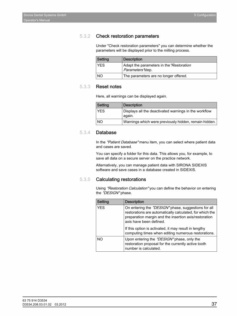
5.3.2 Check restoration parametersCheck restoration parameters
Under "Check restoration parameters" you can determine whether the parameters will be displayed prior to the milling process.
5.3.3 Reset notesReset notes
Here, all warnings can be displayed again.
5.3.4 DatabaseDatabase
In the "Patient Database" menu item, you can select where patient data and cases are saved.
You can specify a folder for this data. This allows you, for example, to save all data on a secure server on the practice network.
Alternatively, you can manage patient data with SIRONA SIDEXIS software and save cases in a database created in SIDEXIS.
5.3.5 Calculating restorationsCalculating restorationsinLab
Using "Restoration Calculation" you can define the behavior on entering the "DESIGN" phase.
Setting DescriptionYES Adapt the parameters in the"Restoration
Parameters"step.NO The parameters are no longer offered.
Setting DescriptionYES Displays all the deactivated warnings in the workflow
again.NO Warnings which were previously hidden, remain hidden.
Setting DescriptionYES On entering the "DESIGN" phase, suggestions for all
restorations are automatically calculated, for which the preparation margin and the insertion axis/restoration axis have been defined.
If this option is activated, it may result in lengthy computing times when editing numerous restorations.
NO Upon entering the "DESIGN" phase, only the restoration proposal for the currently active tooth number is calculated.
63 75 914 D3534D3534.208.03.01.02 03.2012 37

5 Configuration Sirona Dental Systems GmbH5.3 Options Operator's Manual
5.3.6 Auto-hide the page paletteAuto-hide the page palette
The page palette will automatically be minimized if you use a tool.CEREC SW 4 settings
This setting affects the phases MODEL and DESIGN.
Setting DescriptionYES After selecting a tool, the palette will be minimized and
only the symbol of the active tool will be displayed.
The entire palette opens again when the mouse is positioned over it.
Tip: Use this setting if you frequently work with the tool wheel.
NO Provided a tool is selected, the tool palette will always be displayed in its entirety and with all options.
63 75 914 D353438 D3534.208.03.01.02 03.2012
Sirona Dental Systems GmbH 6 Restoration types and design modeOperator's Manual
båÖäáëÜ
6 Restoration types and design modeRestoration types and design mode
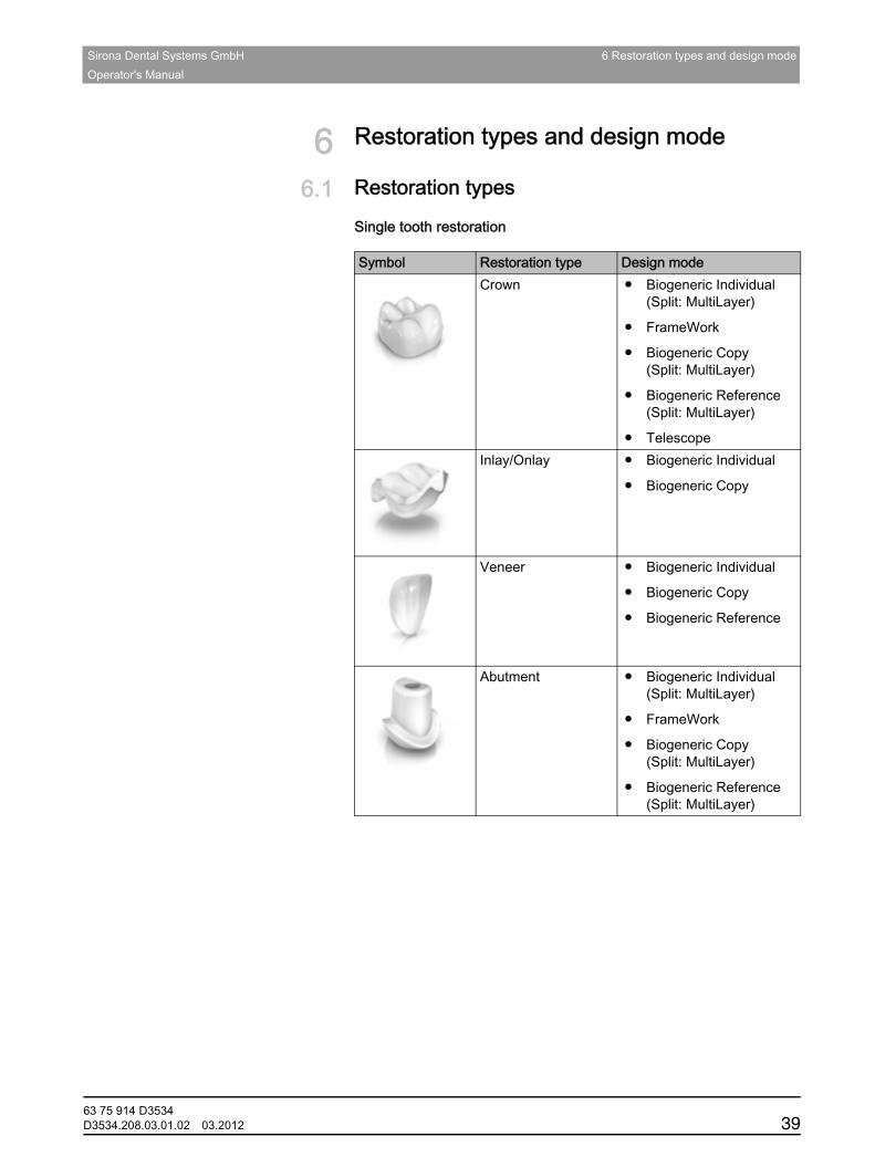
6.1 Restoration typesRestoration types
Single tooth restoration
Symbol Restoration type Design modeCrown ● Biogeneric Individual
(Split: MultiLayer)
● FrameWork
● Biogeneric Copy(Split: MultiLayer)
● Biogeneric Reference(Split: MultiLayer)
● TelescopeInlay/Onlay ● Biogeneric Individual
● Biogeneric Copy
Veneer ● Biogeneric Individual
● Biogeneric Copy
● Biogeneric Reference
Abutment ● Biogeneric Individual(Split: MultiLayer)
● FrameWork
● Biogeneric Copy(Split: MultiLayer)
● Biogeneric Reference(Split: MultiLayer)
63 75 914 D3534D3534.208.03.01.02 03.2012 39

6 Restoration types and design mode Sirona Dental Systems GmbH6.1 Restoration types Operator's Manual
Bridge restoration
Bridge restoration
Symbol Restoration type Design modeCrown ● Biogeneric Individual
● FrameWork
● Biogeneric Copy
● Biogeneric Reference
● TelescopeInlay/Onlay ● Biogeneric Individual
● Biogeneric Copy
Veneer ● Biogeneric Individual
● Biogeneric Copy
● Biogeneric Reference
Pontic ● Biogeneric Individual(Split: MultiLayer)
● FrameWork
● Biogeneric Copy(Split: MultiLayer)
● Biogeneric Reference(Split: MultiLayer)
Missing
Connector ● Intersection
● Anatomic
63 75 914 D353440 D3534.208.03.01.02 03.2012
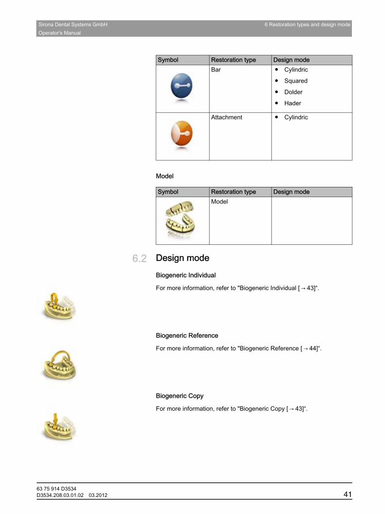
Sirona Dental Systems GmbH 6 Restoration types and design modeOperator's Manual
båÖäáëÜ
Model
Model
6.2 Design modeDesign mode
Biogeneric Individual
For more information, refer to "Biogeneric Individual [ → 43]“.Biogeneric Reference design mode
Biogeneric Reference
For more information, refer to "Biogeneric Reference [ → 44]“.Biogeneric Copy design mode
Biogeneric Copy
For more information, refer to "Biogeneric Copy [ → 43]“.
Bar ● Cylindric
● Squared
● Dolder
● Hader
Attachment ● Cylindric
Symbol Restoration type Design mode
Symbol Restoration type Design modeModel
63 75 914 D3534D3534.208.03.01.02 03.2012 41
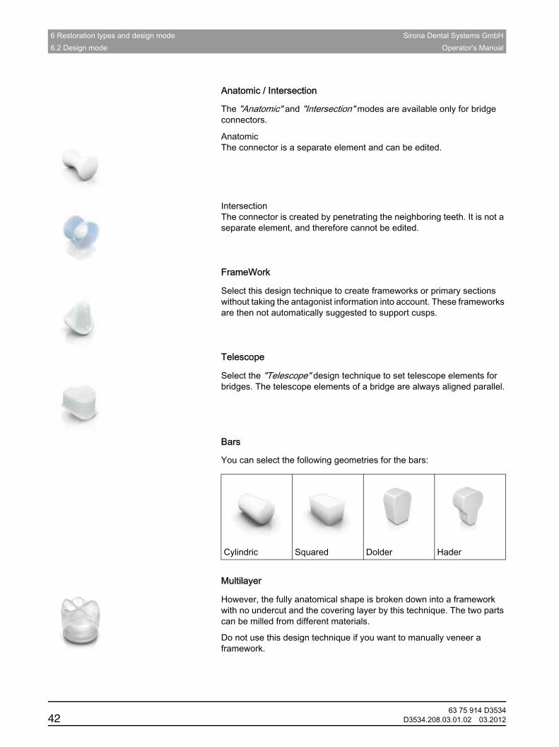
6 Restoration types and design mode Sirona Dental Systems GmbH6.2 Design mode Operator's Manual
Anatomic / Intersection design mode
Anatomic / Intersection
The "Anatomic" and "Intersection" modes are available only for bridge connectors.
Anatomic The connector is a separate element and can be edited.
Intersection The connector is created by penetrating the neighboring teeth. It is not a separate element, and therefore cannot be edited.Framework design mode
FrameWork
Select this design technique to create frameworks or primary sections without taking the antagonist information into account. These frameworks are then not automatically suggested to support cusps.Telescope design mode
Telescope
Select the "Telescope" design technique to set telescope elements for bridges. The telescope elements of a bridge are always aligned parallel.Bars design mode
Bars
You can select the following geometries for the bars:
Multilayer design mode
Multilayer
However, the fully anatomical shape is broken down into a framework with no undercut and the covering layer by this technique. The two parts can be milled from different materials.
Do not use this design technique if you want to manually veneer a framework.
Cylindric Squared Dolder Hader
63 75 914 D353442 D3534.208.03.01.02 03.2012
Sirona Dental Systems GmbH 6 Restoration types and design modeOperator's Manual
båÖäáëÜ
6.3 BiogenericBiogeneric
6.3.1 General information on BiogenericGeneral information on Biogeneric
CEREC Biogeneric is a software that is able to reconstruct lifelike occlusal surfaces. On the basis of the features of a patient's single intact tooth, the program extrapolates the naturally created morphology of other teeth. The biogeneric occlusal design functions for all single tooth restorations and fully anatomic bridges.
Previously, all occlusal design approaches were based on dental libraries and databases containing data records of various standard teeth. Conventional CAD/CAM programs use these dental databases to design a restoration. A tooth that is appropriate for the respective clinical situation is selected from the database. The user then manually edits and adapts this proposal.Crowns, inlays, onlays, veneers, and fully anatomical bridges - inLab
It will now be possible to create crowns, inlays, onlays, veneers, and anatomically sized bridges in a fully automated manner. The reconstruction can be based on any intact patient tooth from the same type, i.e. posterior tooth or anterior tooth.
6.3.2 Biogeneric IndividualBiogeneric Individual
In the "Biogeneric Individual" design technique, the neighboring teeth are analyzed and the restoration suggestion is calculated on this basis. The more information that is available, the more successful the calculation. A full image of at least one neighboring tooth should therefore be taken from the occlusal/incisal direction. For anterior and corner teeth, an image of the labial surface should also be taken.
For premolars or molars, the calculation is mainly based on the distal neighbor, for anterior teeth the mesial neighbor is used.
6.3.3 Biogeneric CopyBiogeneric Copy
Select the "Biogeneric Copy" design technique to transfer parts of an existing occlusal surface to the restoration and enhance the rest using the patented Biogeneric technique.
To do this, acquire the status separately in the "BioCopy Upper" or "BioCopy Lower" image field prior to the preparation.
This technique can be used for inlays, onlays, partial crowns, crowns, and bridges.
63 75 914 D3534D3534.208.03.01.02 03.2012 43

6 Restoration types and design mode Sirona Dental Systems GmbH6.3 Biogeneric Operator's Manual
6.3.4 Biogeneric ReferenceBiogeneric Reference
Select the "Biogeneric Reference" design technique for user definition of the tooth to be used as a reference for calculating the restoration suggestion. The reference tooth can be any tooth of the same class (anterior/posterior tooth), e.g. the antagonist or the contralateral tooth. You also can use a reference tooth from a model to achieve the desired morphology.
This reference tooth must be acquired on a separate basis in the "BioRef Lower" or "BioRef Upper" image field. This technique can be used for inlays, onlays, partial crowns, crowns, and bridges.
63 75 914 D353444 D3534.208.03.01.02 03.2012
Sirona Dental Systems GmbH 7 Edit ordersOperator's Manual
båÖäáëÜ
7 Edit ordersEdit orders
7.1 Tools and functions of the page paletteTools and functions of the page palette
The page palette offers you various different functions, depending on the current step.
7.1.1 ViewsViews
You can use the "View Options" button to display six predefined views.
● "Mesial"● "Distal"● "Buccal" / "Labial"● "Lingual"● "Cervical"● "Occlusal" / "Incisal"
Changing the view
1. Click on the "View Options" button.2. Click on one of the proposed views.
The virtual model rotates to the corresponding view.
Enlarging or reducing the view
1. Click on the "View Options" button.2. Position the mouse pointer over the center tooth icon and press and
hold the left mouse button.The icon then changes to a magnifying glass.
3. Pull the mouse button up or down.The virtual model is then enlarged or reduced.
Tip: You also can use the mouse scrollwheel to enlarge or reduce the view.
7.1.2 ToolsTools
The most important tools are also offered to you in the tool wheel. For more information on the tool wheel, refer to the section Tool wheel [ → 55].
You will find all tools as a submenu under "Tools".Tip: To prevent automatic minimization of the tool window, go to the configuration under "Options" and select the option 'No' in the "Tool-Menu".
Tip: You can cancel the current tool with the stop icon (top right).Undo and reset
Undo and reset With the "Undo" button in the tools you can undo the last change made.
With the "Reset" button you can reset changes that were made with the tool.
63 75 914 D3534D3534.208.03.01.02 03.2012 45

7 Edit orders Sirona Dental Systems GmbH7.1 Tools and functions of the page palette Operator's Manual
7.1.2.1 Buccal registrationBuccal registration
Displacing a buccal image
With the "Drag Buccal" function, you can displace the buccal image.
1. Click on the "Buccal" button.2. Click on the "Drag Buccal" button.3. Click on the buccal image and displace it to the same region on the
upper and the lower jaw.The image is accepted.Tip: If an image is not accepted, align the jaw buccally. This enables better overlapping.If registration is still not possible, check whether the buccal sections in the jaws and in the buccal image are sufficient.
4. If the image was accepted, move the image to the corresponding region of the opposite jaw.
Flipping the buccal acquisition
Rotating a buccal image
With the "Flip Buccal Impression" function, you can rotate the buccal image.
1. Click on the "Buccal" button.2. Click on the "Flip Buccal Impression" button.
The buccal image is then rotated.
7.1.2.2 ShapingShapingWith the "Form" function, you can
● apply
● remove
● or smooth material.Space bar tip
Tip: When one of the shape tools is activated, you can also switch to the following order using the space bar on the keyboard:Apply > Remove > Smooth > Apply > ...Applying material
Apply material
1. Click on the "Form" button.2. Click on the "Add" button.3. Click with the mouse cursor on the area you wish to shape.4. Press and hold the left mouse button and apply the material to the
surface location by moving the mouse.
63 75 914 D353446 D3534.208.03.01.02 03.2012
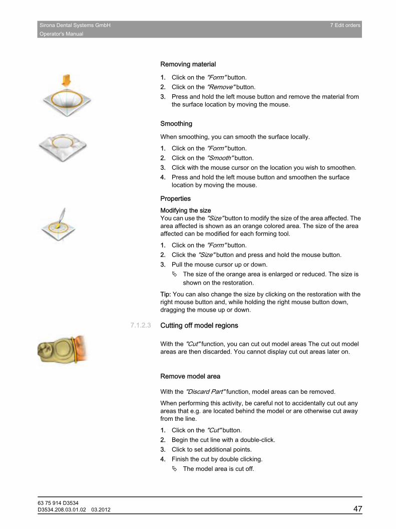
Sirona Dental Systems GmbH 7 Edit ordersOperator's Manual
båÖäáëÜ
Removing material
Removing material
1. Click on the "Form" button.2. Click on the "Remove" button.3. Press and hold the left mouse button and remove the material from
the surface location by moving the mouse.Smoothing
Smoothing
When smoothing, you can smooth the surface locally.
1. Click on the "Form" button.2. Click on the "Smooth" button.3. Click with the mouse cursor on the location you wish to smoothen.4. Press and hold the left mouse button and smoothen the surface
location by moving the mouse.
PropertiesResizingModifying the size You can use the "Size" button to modify the size of the area affected. The area affected is shown as an orange colored area. The size of the area affected can be modified for each forming tool.
1. Click on the "Form" button.2. Click the "Size" button and press and hold the mouse button.3. Pull the mouse cursor up or down.
The size of the orange area is enlarged or reduced. The size is shown on the restoration.
Tip: You can also change the size by clicking on the restoration with the right mouse button and, while holding the right mouse button down, dragging the mouse up or down.
7.1.2.3 Cutting off model regionsCutting off model regions
Cutting with CEREC SW 4
With the "Cut" function, you can cut out model areas The cut out model areas are then discarded. You cannot display cut out areas later on.
Remove model areaActivity
With the "Discard Part" function, model areas can be removed.
When performing this activity, be careful not to accidentally cut out any areas that e.g. are located behind the model or are otherwise cut away from the line.
1. Click on the "Cut" button.2. Begin the cut line with a double-click.3. Click to set additional points.4. Finish the cut by double clicking.
The model area is cut off.
63 75 914 D3534D3534.208.03.01.02 03.2012 47
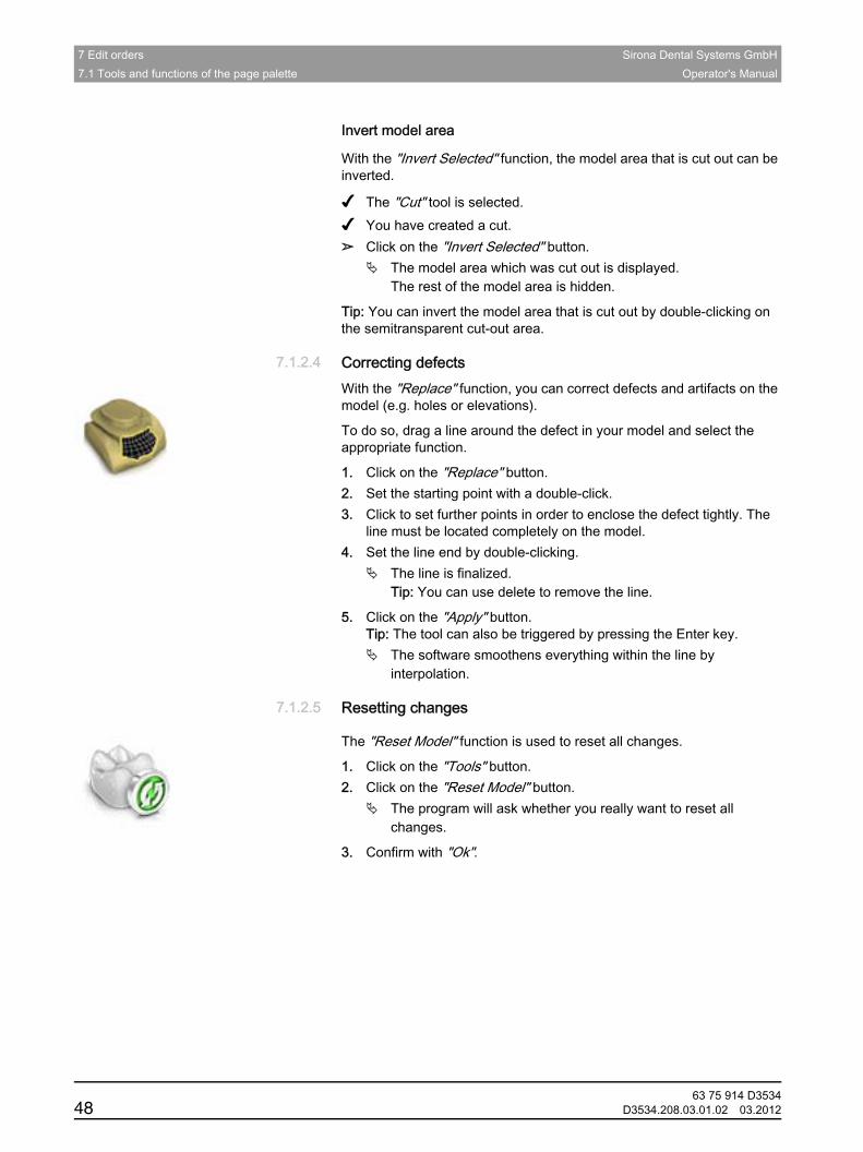
7 Edit orders Sirona Dental Systems GmbH7.1 Tools and functions of the page palette Operator's Manual
Invert model area
With the "Invert Selected" function, the model area that is cut out can be inverted.
✔ The "Cut" tool is selected.✔ You have created a cut.➢ Click on the "Invert Selected" button.
The model area which was cut out is displayed.The rest of the model area is hidden.
Tip: You can invert the model area that is cut out by double-clicking on the semitransparent cut-out area.
7.1.2.4 Correcting defectsCorrecting defectsWith the "Replace" function, you can correct defects and artifacts on the model (e.g. holes or elevations).
To do so, drag a line around the defect in your model and select the appropriate function.
1. Click on the "Replace" button.2. Set the starting point with a double-click.3. Click to set further points in order to enclose the defect tightly. The
line must be located completely on the model.4. Set the line end by double-clicking.
The line is finalized.Tip: You can use delete to remove the line.
5. Click on the "Apply" button. Tip: The tool can also be triggered by pressing the Enter key.
The software smoothens everything within the line by interpolation.
7.1.2.5 Resetting changesResetting changes
The "Reset Model" function is used to reset all changes.
1. Click on the "Tools" button.2. Click on the "Reset Model" button.
The program will ask whether you really want to reset all changes.
3. Confirm with "Ok".
63 75 914 D353448 D3534.208.03.01.02 03.2012

Sirona Dental Systems GmbH 7 Edit ordersOperator's Manual
båÖäáëÜ
7.1.2.6 TrimmingTrimmingWith the "Trim" function, you can isolate the preparation. You can thus e.g. draw in the preparation margin more easily. Trimmed image regions can be optionally displayed and hidden later on.Remove part
Hiding image regions
The "Discard Part" function enables you to hide image regions.
The trim line also can be placed over the preparation line. Only the region underneath the preparation will then be hidden automatically. The prepared region remains fully intact.
1. Click on the "Trim" button.2. Click on the "Discard Part" button.3. Start by double-clicking in the vicinity of the model or on the model.4. Click to set additional points. Draw the line close to the preparation
around which you want to trim.5. Finish the line by double clicking.
The smaller region of the model is hidden.Invert selected
Inverting an image region
With the "Invert Selected" function, the hidden image region can be inverted.
✔ An image region has been hidden using the "Trim" tool.➢ Click on the "Invert Selected" button.
The hidden image region will be shown.The image region shown will be hidden.
Tip: You can invert the hidden image region by double-clicking on the semitransparent hidden region.
7.1.2.7 Entering the preparation marginEntering the preparation marginGeneral
For further information on using this tool, see the section Entering the preparation margin [ → 85].Automatic edge detection
Automatic edge detection
With "Margin" / "Auto", you can work with automatic edge detection.
1. Click on the "Margin" button.2. Click on the "Auto" button.
Automatic edge detection is switched on.Interpolating technique
63 75 914 D3534D3534.208.03.01.02 03.2012 49
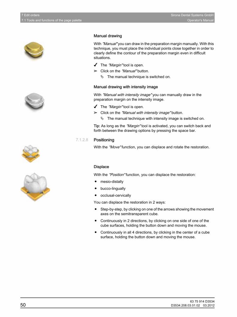
7 Edit orders Sirona Dental Systems GmbH7.1 Tools and functions of the page palette Operator's Manual
Manual drawing
With "Manual" you can draw in the preparation margin manually. With this technique, you must place the individual points close together in order to clearly define the contour of the preparation margin even in difficult situations.
✔ The "Margin" tool is open.➢ Click on the "Manual" button.
The manual technique is switched on.Interpolating technique with intensity image
Manual drawing with intensity image
With "Manual with intensity image" you can manually draw in the preparation margin on the intensity image.
✔ The "Margin" tool is open.➢ Click on the "Manual with intensity image" button.
The manual technique with intensity image is switched on.
Tip: As long as the "Margin" tool is activated, you can switch back and forth between the drawing options by pressing the space bar.
7.1.2.8 PositioningPositioningWith the "Move" function, you can displace and rotate the restoration.Positioning
Displace
With the "Position" function, you can displace the restoration:
● mesio-distally
● bucco-lingually
● occlusal-cervically
You can displace the restoration in 2 ways:
● Step-by-step, by clicking on one of the arrows showing the movement axes on the semitransparent cube.
● Continuously in 2 directions, by clicking on one side of one of the cube surfaces, holding the button down and moving the mouse.
● Continuously in all 4 directions, by clicking in the center of a cube surface, holding the button down and moving the mouse.
Rotate
63 75 914 D353450 D3534.208.03.01.02 03.2012
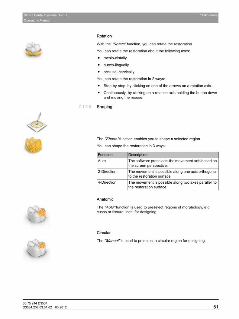
Sirona Dental Systems GmbH 7 Edit ordersOperator's Manual
båÖäáëÜ
Rotation
With the "Rotate" function, you can rotate the restoration
You can rotate the restoration about the following axes:
● mesio-distally
● bucco-lingually
● occlusal-cervically
You can rotate the restoration in 2 ways:
● Step-by-step, by clicking on one of the arrows on a rotation axis.
● Continuously, by clicking on a rotation axis holding the button down and moving the mouse.
7.1.2.9 ShapingShaping
General
The "Shape" function enables you to shape a selected region.
You can shape the restoration in 3 ways:
Automatic
Anatomic
The "Auto" function is used to preselect regions of morphology, e.g. cusps or fissure lines, for designing.Manual
Circular
The "Manual" is used to preselect a circular region for designing.
Function DescriptionAuto The software preselects the movement axis based on
the screen perspective.2-Direction The movement is possible along one axis orthogonal
to the restoration surface.4-Direction The movement is possible along two axes parallel to
the restoration surface.
63 75 914 D3534D3534.208.03.01.02 03.2012 51
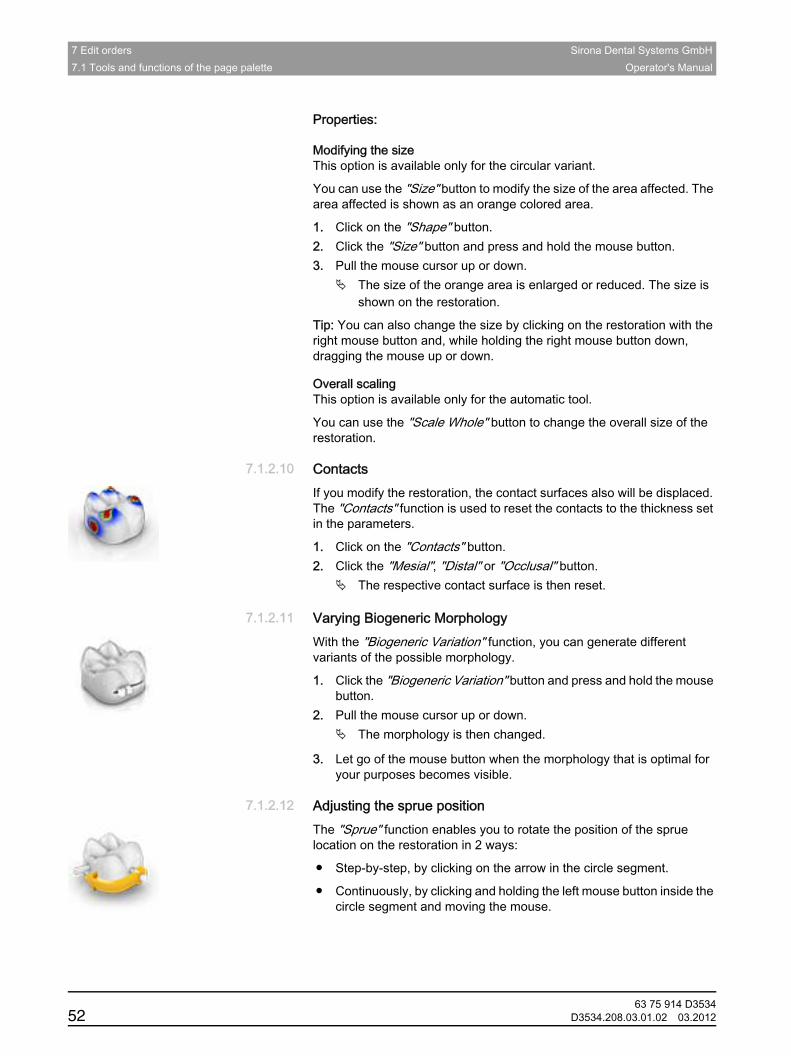
7 Edit orders Sirona Dental Systems GmbH7.1 Tools and functions of the page palette Operator's Manual
Properties:Modifying the size
Modifying the size This option is available only for the circular variant.
You can use the "Size" button to modify the size of the area affected. The area affected is shown as an orange colored area.
1. Click on the "Shape" button.2. Click the "Size" button and press and hold the mouse button.3. Pull the mouse cursor up or down.
The size of the orange area is enlarged or reduced. The size is shown on the restoration.
Tip: You can also change the size by clicking on the restoration with the right mouse button and, while holding the right mouse button down, dragging the mouse up or down.Scale whole
Overall scaling This option is available only for the automatic tool.
You can use the "Scale Whole" button to change the overall size of the restoration.
7.1.2.10 ContactsContactsIf you modify the restoration, the contact surfaces also will be displaced. The "Contacts" function is used to reset the contacts to the thickness set in the parameters.
1. Click on the "Contacts" button.2. Click the "Mesial", "Distal" or "Occlusal" button.
The respective contact surface is then reset.
7.1.2.11 Varying Biogeneric MorphologyVarying Biogeneric MorphologyWith the "Biogeneric Variation" function, you can generate different variants of the possible morphology.
1. Click the "Biogeneric Variation" button and press and hold the mouse button.
2. Pull the mouse cursor up or down.The morphology is then changed.
3. Let go of the mouse button when the morphology that is optimal for your purposes becomes visible.
7.1.2.12 Adjusting the sprue positionAdjusting the sprue positionThe "Sprue" function enables you to rotate the position of the sprue location on the restoration in 2 ways:
● Step-by-step, by clicking on the arrow in the circle segment.
● Continuously, by clicking and holding the left mouse button inside the circle segment and moving the mouse.
63 75 914 D353452 D3534.208.03.01.02 03.2012
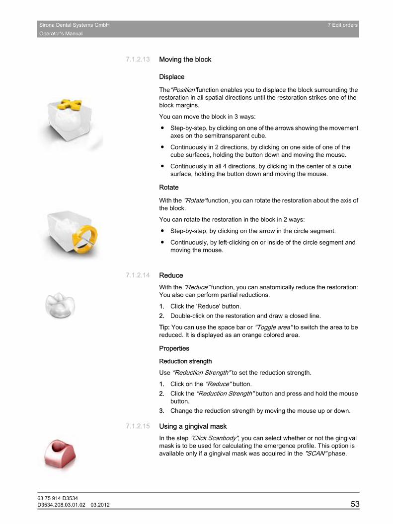
Sirona Dental Systems GmbH 7 Edit ordersOperator's Manual
båÖäáëÜ
7.1.2.13 Moving the blockMoving the block
Displace
The"Position"function enables you to displace the block surrounding the restoration in all spatial directions until the restoration strikes one of the block margins.
You can move the block in 3 ways:
● Step-by-step, by clicking on one of the arrows showing the movement axes on the semitransparent cube.
● Continuously in 2 directions, by clicking on one side of one of the cube surfaces, holding the button down and moving the mouse.
● Continuously in all 4 directions, by clicking in the center of a cube surface, holding the button down and moving the mouse.
Rotate
With the "Rotate"function, you can rotate the restoration about the axis of the block.
You can rotate the restoration in the block in 2 ways:
● Step-by-step, by clicking on the arrow in the circle segment.
● Continuously, by left-clicking on or inside of the circle segment and moving the mouse.
7.1.2.14 ReduceReduceWith the "Reduce" function, you can anatomically reduce the restoration: You also can perform partial reductions.
1. Click the 'Reduce' button.2. Double-click on the restoration and draw a closed line.
Tip: You can use the space bar or "Toggle area" to switch the area to be reduced. It is displayed as an orange colored area.
Properties
Reduction strength
Use "Reduction Strength" to set the reduction strength.
1. Click on the "Reduce" button.2. Click the "Reduction Strength" button and press and hold the mouse
button.3. Change the reduction strength by moving the mouse up or down.
7.1.2.15 Using a gingival maskUsing a gingival maskIn the step "Click Scanbody", you can select whether or not the gingival mask is to be used for calculating the emergence profile. This option is available only if a gingival mask was acquired in the "SCAN" phase.
63 75 914 D3534D3534.208.03.01.02 03.2012 53

7 Edit orders Sirona Dental Systems GmbH7.1 Tools and functions of the page palette Operator's Manual
7.1.2.16 DimensionDimension
With the "Dimension" function, you can enlarge or reduce crowns, pontics and abutments in different directions.
7.1.2.17 ScaleScaleYou can use this tool for frameworks, telescopes, multilayer frameworks and bars.
In the tool menu, you can select whether the tool is to be effective in the radial or the occlusal direction. You can toggle between these directions with the space bar or with the mouse.
1. Place the mouse pointer on an active restoration.Various design elements are then offered, depending on the restoration type.
An arrow shows the direction in which the scaling will occur. The area affected is shown highlighted in orange.
2. Press and hold down the left mouse button.3. Move the mouse to change the object.
Properties
Modifying the size
If a check mark is placed in front of"Complete"the area affected is maximized and applies to the entire design element. If no check mark is placed, you can determine the area affected individually.
You can use the "Size"button to modify the size of the area affected. The area affected is shown as an orange colored area. The size of the area affected can be modified for each forming tool.
1. Click on the "Scale" button.2. Click the"Size"button and press and hold the mouse button.3. Pull the mouse cursor up or down.
"Complete" The entire restoration is enlarged or reduced in all directions
"Buccal-Lingual" The restoration is enlarged or reduced only in the bucco-lingual direction
"Mesial-Distal" The restoration is enlarged or reduced only in the mesio-distal direction.
63 75 914 D353454 D3534.208.03.01.02 03.2012
Sirona Dental Systems GmbH 7 Edit ordersOperator's Manual
båÖäáëÜ
The size of the orange area is enlarged or reduced. The size is shown on the restoration.
Tip:You can also change the size by clicking on the restoration with the right mouse button and, while holding the right mouse button down, dragging the mouse up or down.
7.1.2.18 Subtract Attachment from PonticSubtract Attachment from Pontic
If you click on this tool, the cavity in the restoration element to be mounted is calculated. The cavity design must be finished for this purpose.
7.1.2.19 Tool wheelTool wheelDescription of CEREC SW 4
The tool wheel makes the standard tools available in the MODEL and DESIGN phases in order to simplify access. The tools currently available vary depending on the current step.
1. Right-click in the workspace.The tool wheel opens.
2. Click with the right mouse button anywhere in the workspace.The tool wheel moves to the position of the mouse pointer.
3. Select a tool.The selected tool is available. The tool wheel closes automatically.
You also can close the tool by clicking in the workspace with the left mouse button.
7.1.3 Displaying objectsDisplaying objectsDescription
You can use these functions to display and hide the region of the model and that of the restorations.
1. Click on the "View Options" button.2. Click the respective button.
The affected region is then displayed or hidden.
63 75 914 D3534D3534.208.03.01.02 03.2012 55
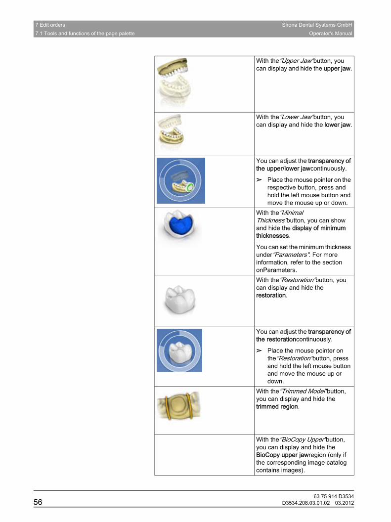
7 Edit orders Sirona Dental Systems GmbH7.1 Tools and functions of the page palette Operator's Manual
Overview
With the"Upper Jaw"button, you can display and hide the upper jaw.
With the"Lower Jaw"button, you can display and hide the lower jaw.
You can adjust the transparency of the upper/lower jawcontinuously.
➢ Place the mouse pointer on the respective button, press and hold the left mouse button and move the mouse up or down.
With the"Minimal Thickness"button, you can show and hide the display of minimum thicknesses.
You can set the minimum thickness under"Parameters". For more information, refer to the section onParameters.With the"Restoration"button, you can display and hide the restoration.
You can adjust the transparency of the restorationcontinuously.
➢ Place the mouse pointer on the"Restoration"button, press and hold the left mouse button and move the mouse up or down.
With the"Trimmed Model"button, you can display and hide the trimmed region.
With the"BioCopy Upper"button, you can display and hide the BioCopy upper jawregion (only if the corresponding image catalog contains images).
63 75 914 D353456 D3534.208.03.01.02 03.2012
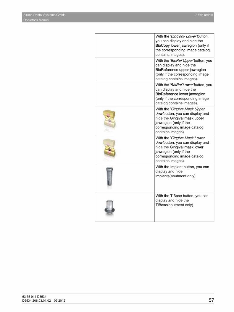
Sirona Dental Systems GmbH 7 Edit ordersOperator's Manual
båÖäáëÜ
With the"BioCopy Lower"button, you can display and hide the BioCopy lower jawregion (only if the corresponding image catalog contains images).With the"BioRef Upper"button, you can display and hide the BioReference upper jawregion (only if the corresponding image catalog contains images). With the"BioRef Lower"button, you can display and hide the BioReference lower jawregion (only if the corresponding image catalog contains images).With the"Gingiva Mask Upper Jaw"button, you can display and hide the Gingival mask upper jawregion (only if the corresponding image catalog contains images).With the"Gingiva Mask Lower Jaw"button, you can display and hide the Gingival mask lower jawregion (only if the corresponding image catalog contains images).With the Implant button, you can display and hide implants(abutment only).
With the TiBase button, you can display and hide the TiBase(abutment only).
63 75 914 D3534D3534.208.03.01.02 03.2012 57

7 Edit orders Sirona Dental Systems GmbH7.1 Tools and functions of the page palette Operator's Manual
7.1.4 Analysis toolsAnalysis tools
Contact surfaces on the virtual model
Using the "Model Contacts" button, the contact surfaces on the virtual model can be displayed or hidden.
1. Click on the "Analyzing Tools" button.2. Click on the "Model Contacts" button.
The contact areas on the model are displayed or hidden.
Contact surfaces on the restoration
Contact surfaces on the restoration
You can use the page palette button to check the occlusal contact points of the jaws.
The same color scheme is used as when displaying the contacts to the neighboring teeth or to the opposing jaw.
Side and bottom surfaces
Side and bottom surfaces
Using the "Model Box" button, the virtual model can be displayed without the sides and bottom.
1. Click on the "Analyzing Tools" button.2. Click on the "Model Box" button.
The virtual model is displayed without side and bottom surfaces.Tip: Mill
Tip: In the MILL phase show the relevant jaw model (show reference objects) and hide the bottom of the model in order to check the fit from all sides.This enables you to check the tightly sealed preparation limit and check whether the ceramic extends through the preparation. This is a reference to areas where the restoration may be too low.
Penetration/pressure:
Distance:
> 100 µm100 - 50 µm50 - 0 µm
0 - 50 µm50 - 100 µm> 100 µm
Penetration/pressure:
Distance:
> 100 µm100 - 50 µm50 - 0 µm
0 - 50 µm50 - 100 µm> 100 µm
63 75 914 D353458 D3534.208.03.01.02 03.2012
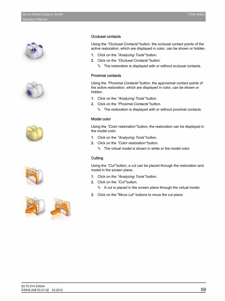
Sirona Dental Systems GmbH 7 Edit ordersOperator's Manual
båÖäáëÜ
Occlusal contacts
Occlusal contacts
Using the "Occlusal Contacts" button, the occlusal contact points of the active restoration, which are displayed in color, can be shown or hidden.
1. Click on the "Analyzing Tools" button.2. Click on the "Occlusal Contacts" button.
The restoration is displayed with or without occlusal contacts.Proximal contacts
Proximal contacts
Using the "Proximal Contacts" button, the approximal contact points of the active restoration. which are displayed in color, can be shown or hidden.
1. Click on the "Analyzing Tools" button.2. Click on the "Proximal Contacts" button.
The restoration is displayed with or without proximal contacts.Model color
Model color
Using the "Color restoration" button, the restoration can be displayed in the model color.
1. Click on the "Analyzing Tools" button.2. Click on the "Color restoration" button.
The virtual model is shown in white or the model color.Cut
Cutting
Using the "Cut" button, a cut can be placed through the restoration and model in the screen plane.
1. Click on the "Analyzing Tools" button.2. Click on the "Cut" button.
A cut is placed in the screen plane through the virtual model.
3. Click on the "Move cut" buttons to move the cut plane.Cursor details
63 75 914 D3534D3534.208.03.01.02 03.2012 59
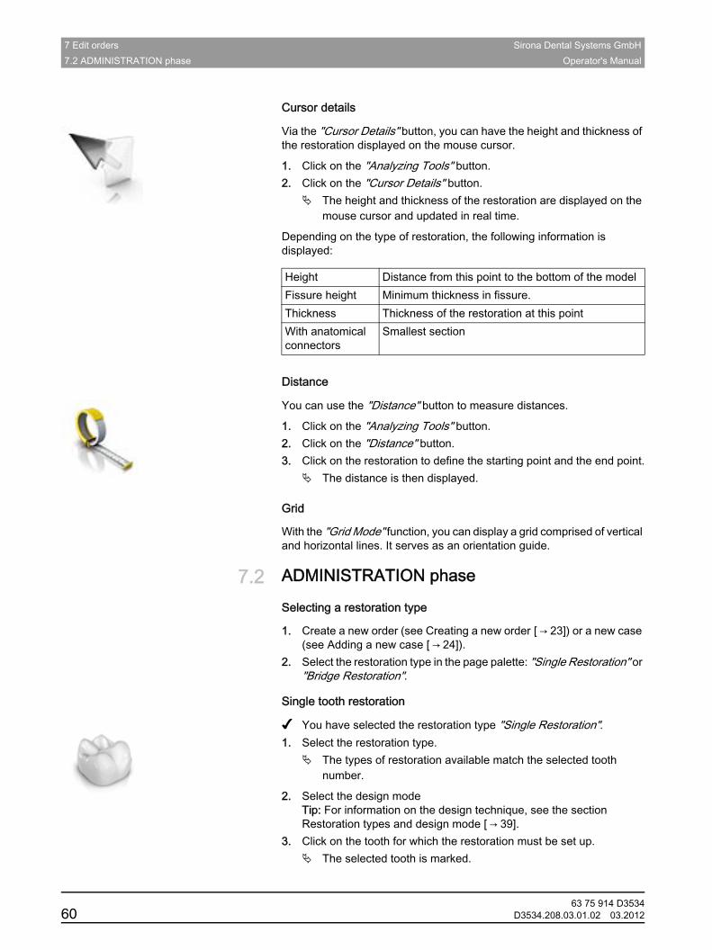
7 Edit orders Sirona Dental Systems GmbH7.2 ADMINISTRATION phase Operator's Manual
Cursor details
Via the "Cursor Details" button, you can have the height and thickness of the restoration displayed on the mouse cursor.
1. Click on the "Analyzing Tools" button.2. Click on the "Cursor Details" button.
The height and thickness of the restoration are displayed on the mouse cursor and updated in real time.
Depending on the type of restoration, the following information is displayed:
Distance
Distance
You can use the "Distance" button to measure distances.
1. Click on the "Analyzing Tools" button.2. Click on the "Distance" button.3. Click on the restoration to define the starting point and the end point.
The distance is then displayed.Grid
Grid
With the "Grid Mode" function, you can display a grid comprised of vertical and horizontal lines. It serves as an orientation guide.
7.2 ADMINISTRATION phaseADMINISTRATION phase
Selecting a restoration type
1. Create a new order (see Creating a new order [ → 23]) or a new case (see Adding a new case [ → 24]).
2. Select the restoration type in the page palette: "Single Restoration" or "Bridge Restoration".
inLab SW 4 single tooth restoration
Single tooth restoration
✔ You have selected the restoration type "Single Restoration".1. Select the restoration type.
The types of restoration available match the selected tooth number.
2. Select the design mode Tip: For information on the design technique, see the section Restoration types and design mode [ → 39].
3. Click on the tooth for which the restoration must be set up.The selected tooth is marked.
Height Distance from this point to the bottom of the modelFissure height Minimum thickness in fissure.Thickness Thickness of the restoration at this pointWith anatomical connectors
Smallest section
63 75 914 D353460 D3534.208.03.01.02 03.2012

Sirona Dental Systems GmbH 7 Edit ordersOperator's Manual
båÖäáëÜ
4. In the step menu, click on the step "Select Material" to select the manufacturer and the material.You must select 2 materials for the restoration type 'Multilayer'.You must select an implant type for the restoration type 'Abutment'.
5. Optional: In the step menu, click on the step "Select Milling Device" to change the current milling unit.
6. Confirm the settings by clicking "Ok".Tip: If you click on "Cancel" the restoration will not be created and the program will return to the odontogram.
7. If necessary, create further restorations.inLab SW 4 bridge restoration
Bridge restoration
✔ You have selected the restoration type "Bridge Restoration".1. Determine the restoration type and the design mode for the abutment
teeth as described in the section ADMINISTRATION phase [ → 60] .2. Select the positions of the abutment teeth of the bridge.
The selected teeth are marked.
3. Determine the restoration type and the design mode for the intermediate teeth.
The selected teeth are marked.
4. In the step menu, click on the step "Select Material" to select the manufacturer and the material.
5. Optional: In the step menu, click on the step "Select Milling Device" to change the current milling unit.
6. Confirm the settings by clicking "Ok".Tip: If you click on "Cancel" the restoration will not be created and the program will return to the odontogram.
7. If necessary, create further restorations.Editing the restoration
Editing the restoration
You can edit previously created restorations.
1. Click on the restoration in the object bar.2. Select the "Edit Restoration" step.3. To change the restoration type and the design mode, proceed as
when creating a new restoration. Important: To do this, click on the restoration concerned in the tooth model!
4. Confirm your changes by clicking the "Ok" button.Finishing the administration phase
Finishing the ADMINISTRATION phase
✔ All restorations to be created are defined.✔ The "ACQUISITION" phase is can be selected.➢ Click on the "ACQUISITION" phase.or
➢ Click on the double arrow.
The program switches over to the "ACQUISITION" phase.
63 75 914 D3534D3534.208.03.01.02 03.2012 61
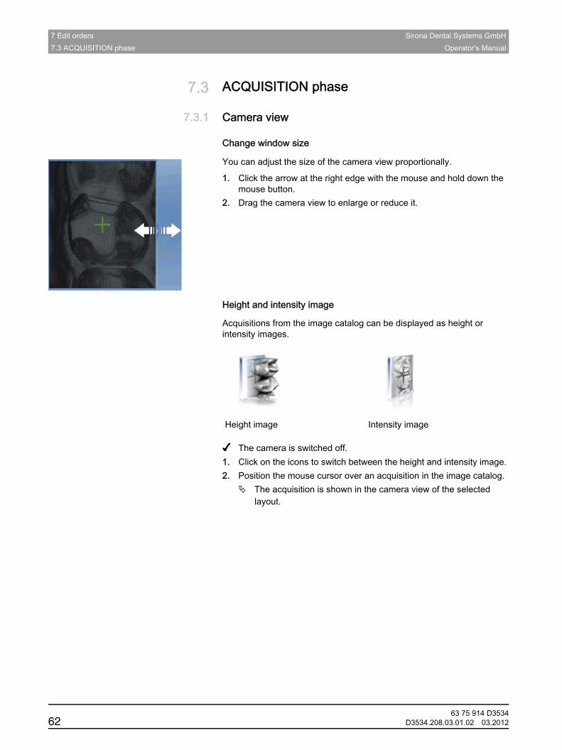
7 Edit orders Sirona Dental Systems GmbH7.3 ACQUISITION phase Operator's Manual
7.3 ACQUISITION phaseACQUISITION phase
7.3.1 Camera viewCamera view
Change window size
You can adjust the size of the camera view proportionally.
1. Click the arrow at the right edge with the mouse and hold down the mouse button.
2. Drag the camera view to enlarge or reduce it.
Height and intensity image
Acquisitions from the image catalog can be displayed as height or intensity images.
✔ The camera is switched off.1. Click on the icons to switch between the height and intensity image.2. Position the mouse cursor over an acquisition in the image catalog.
The acquisition is shown in the camera view of the selected layout.
Height image Intensity image
63 75 914 D353462 D3534.208.03.01.02 03.2012

Sirona Dental Systems GmbH 7 Edit ordersOperator's Manual
båÖäáëÜ
7.3.2 inEos BlueinEos Blue
7.3.2.1 GeneralGeneralAcquisition methods
You have three modes for executing scans with inEos Blue:
● Grid scan– For big jobs with 9 or more units– Long, untoothed areas
● Free scan– For jobs comprising up to 8 units– For detail scans under various angles
● Rotational scan– For measuring single tooth stumps– For single restorations without consideration of the proximal contacts or the antagonist
You can execute several scan modes in sequence.
You can omit a scan mode if, for example, it is not suitable for your model.Scan models
Scan modelsMaterials
You can scan all materials that correspond to the following criteria:
● Non-reflecting
● Nontransparent
● No transparent parts
● Not highly absorbent (e.g. heavily colored plasters)
Unscannable materials generate artifacts in the image.
Tip: When using plasters that do not meet the above criteria, you must powder the affected areas. Otherwise the measuring accuracy will be impaired considerably.The following are suitable for this purpose: CEREC Optispray (REF 61 44 179)
For scanning with inEos Blue, we recommend using CEREC Stone BC plaster (REF 62 37 502).Saw-cut etc.
● When preparing saw-cut models, be careful not to mill off the single stump segments. Place the model next to the stumps so that the scanner can properly capture these areas.
● Create only a slight fluting below the preparation margin.Focusing the image
63 75 914 D3534D3534.208.03.01.02 03.2012 63
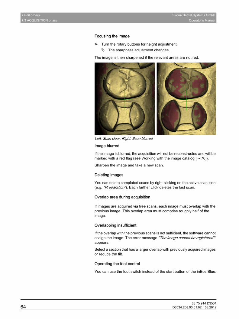
7 Edit orders Sirona Dental Systems GmbH7.3 ACQUISITION phase Operator's Manual
Focusing the imageFocusing the image
➢ Turn the rotary buttons for height adjustment.The sharpness adjustment changes.
The image is then sharpened if the relevant areas are not red.
Left: Scan clear; Right: Scan blurredObject blurred - inLab SW
Image blurred
If the image is blurred, the acquisition will not be reconstructed and will be marked with a red flag (see Working with the image catalog [ → 76]).
Sharpen the image and take a new scan.Deleting images
Deleting images
You can delete completed scans by right-clicking on the active scan icon (e.g. "Preparation"). Each further click deletes the last scan.Overlap area during acquisition
Overlap area during acquisitionOverlap area
If images are acquired via free scans, each image must overlap with the previous image. This overlap area must comprise roughly half of the image.Overlapping insufficient from inLab SW
Overlapping insufficient
If the overlap with the previous scans is not sufficient, the software cannot assign the image. The error message "The image cannot be registered!" appears.
Select a section that has a larger overlap with previously acquired images or reduce the tilt.Operating the foot control
Operating the foot control
You can use the foot switch instead of the start button of the inEos Blue.
63 75 914 D353464 D3534.208.03.01.02 03.2012

Sirona Dental Systems GmbH 7 Edit ordersOperator's Manual
båÖäáëÜ
7.3.2.2 Switching the inEos Blue on/offSwitching the inEos Blue on/off
The inEos Blue is turned on automatically when you switch to the acquisition phase. If the inEos Blue is not used for some time, it will switch off automatically.
➢ Click on the inEos icon to switch the inEos Blue on or off.
7.3.2.3 Grid scansGrid scans
● For big jobs with 9 or more units
● Long, untoothed areasPreparing the model
Preparing the model
1. Secure the model to the model holder included. The labial side faces the fixing screw.
2. Release the ball and socket joint.3. Align the model:
The model is horizontal and the front teeth stand parallel to a triangle side.
4. Remove the sliding block from the model holder.Taking the scan
Taking the scan
Tip: Do not change the position of the ball-and-socket joint during acquisition.
NOTICE Do not damage the shifting plate
Do not apply any pressure to the model when it is located on the shifting plate. Doing so could damage the shifting plate.
63 75 914 D3534D3534.208.03.01.02 03.2012 65

7 Edit orders Sirona Dental Systems GmbH7.3 ACQUISITION phase Operator's Manual
1. Place the model holder on the shifting plate. The small balls must lodge in the longitudinal and transverse grooves. The tip of the model holder plate and the oral side of the model face the column of the inEos Blue.
2. Click the icon for grid scans.A section of the model appears in the the live image.
3. Slide the model until you can begin scan acquisition on a distal side.4. Focus the image by turning the rotary buttons for height adjustment,
see Focusing the image.Do not touch the rotary buttons while the scans are being taken.
5. Single-click the Start button of the inEos Blue.The image is acquired.
6. Add additional scans from adjacent areas: Move the model in the desired direction by one stop position and repeat steps 4 to 5.
If you do not require any further grid scans, you can change to the next acquisition mode; see Free scans or Rotational scans.
Tip: If a bite registration is to be acquired, additional mesial and distal areas also must be scanned. These areas must not be concealed by the bite registration.
7.3.2.4 Free scansFree scans
You can use detail scans for example to detect undercuts which were not detected by the overview scans.
● For scans with up to and including 8 units
● For additional scans at different angles
63 75 914 D353466 D3534.208.03.01.02 03.2012
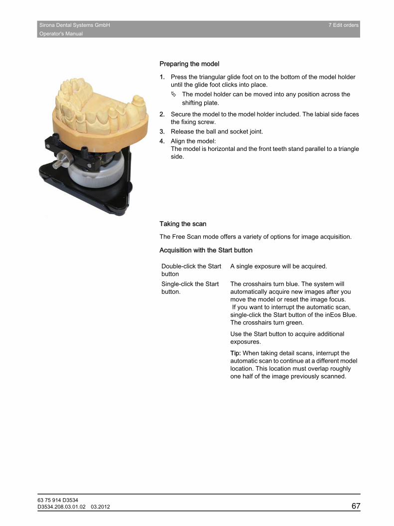
Sirona Dental Systems GmbH 7 Edit ordersOperator's Manual
båÖäáëÜ
Preparing the model
Preparing the model
1. Press the triangular glide foot on to the bottom of the model holder until the glide foot clicks into place.
The model holder can be moved into any position across the shifting plate.
2. Secure the model to the model holder included. The labial side faces the fixing screw.
3. Release the ball and socket joint.4. Align the model:
The model is horizontal and the front teeth stand parallel to a triangle side.
Taking the scan
Taking the scan
The Free Scan mode offers a variety of options for image acquisition.
Acquisition with the Start button
Double-click the Start button
A single exposure will be acquired.
Single-click the Start button.
The crosshairs turn blue. The system will automatically acquire new images after you move the model or reset the image focus. If you want to interrupt the automatic scan, single-click the Start button of the inEos Blue. The crosshairs turn green.
Use the Start button to acquire additional exposures.
Tip: When taking detail scans, interrupt the automatic scan to continue at a different model location. This location must overlap roughly one half of the image previously scanned.
63 75 914 D3534D3534.208.03.01.02 03.2012 67
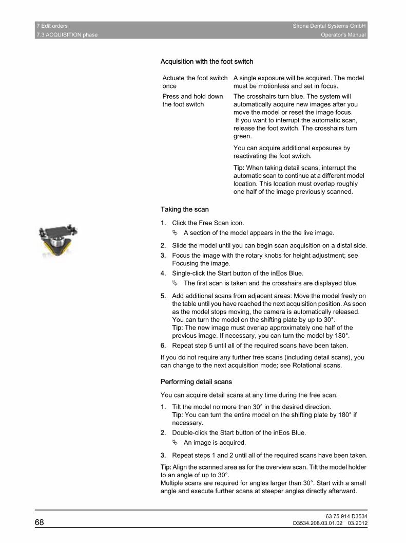
7 Edit orders Sirona Dental Systems GmbH7.3 ACQUISITION phase Operator's Manual
Acquisition with the foot switch
Taking the scan
1. Click the Free Scan icon.A section of the model appears in the the live image.
2. Slide the model until you can begin scan acquisition on a distal side.3. Focus the image with the rotary knobs for height adjustment; see
Focusing the image.4. Single-click the Start button of the inEos Blue.
The first scan is taken and the crosshairs are displayed blue.
5. Add additional scans from adjacent areas: Move the model freely on the table until you have reached the next acquisition position. As soon as the model stops moving, the camera is automatically released. You can turn the model on the shifting plate by up to 30°.Tip: The new image must overlap approximately one half of the previous image. If necessary, you can turn the model by 180°.
6. Repeat step 5 until all of the required scans have been taken.
If you do not require any further free scans (including detail scans), you can change to the next acquisition mode; see Rotational scans.Performing detail scans
Performing detail scans
You can acquire detail scans at any time during the free scan.
1. Tilt the model no more than 30° in the desired direction.Tip: You can turn the entire model on the shifting plate by 180° if necessary.
2. Double-click the Start button of the inEos Blue.An image is acquired.
3. Repeat steps 1 and 2 until all of the required scans have been taken.
Tip: Align the scanned area as for the overview scan. Tilt the model holder to an angle of up to 30°.Multiple scans are required for angles larger than 30°. Start with a small angle and execute further scans at steeper angles directly afterward.
Actuate the foot switch once
A single exposure will be acquired. The model must be motionless and set in focus.
Press and hold down the foot switch
The crosshairs turn blue. The system will automatically acquire new images after you move the model or reset the image focus. If you want to interrupt the automatic scan, release the foot switch. The crosshairs turn green.
You can acquire additional exposures by reactivating the foot switch.
Tip: When taking detail scans, interrupt the automatic scan to continue at a different model location. This location must overlap roughly one half of the image previously scanned.
63 75 914 D353468 D3534.208.03.01.02 03.2012
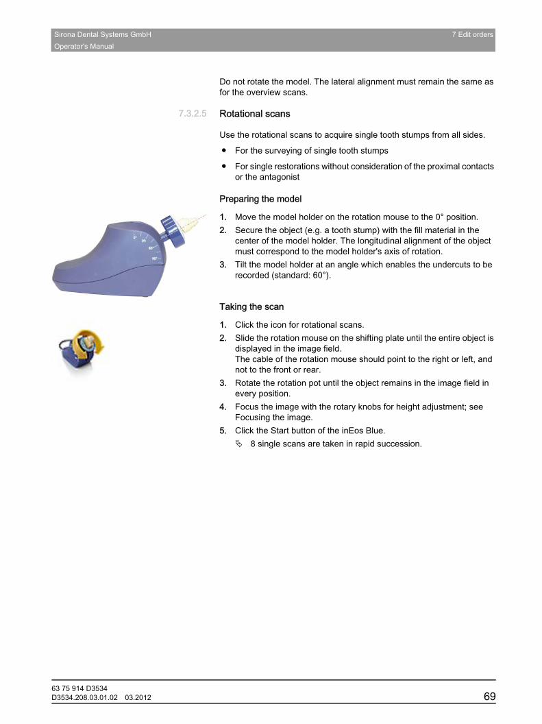
Sirona Dental Systems GmbH 7 Edit ordersOperator's Manual
båÖäáëÜ
Do not rotate the model. The lateral alignment must remain the same as for the overview scans.
7.3.2.5 Rotational scansRotational scans
Use the rotational scans to acquire single tooth stumps from all sides.
● For the surveying of single tooth stumps
● For single restorations without consideration of the proximal contacts or the antagonist
Preparing the model
Preparing the model
1. Move the model holder on the rotation mouse to the 0° position.2. Secure the object (e.g. a tooth stump) with the fill material in the
center of the model holder. The longitudinal alignment of the object must correspond to the model holder's axis of rotation.
3. Tilt the model holder at an angle which enables the undercuts to be recorded (standard: 60°).
Taking the scan
Taking the scan
1. Click the icon for rotational scans.2. Slide the rotation mouse on the shifting plate until the entire object is
displayed in the image field. The cable of the rotation mouse should point to the right or left, and not to the front or rear.
3. Rotate the rotation pot until the object remains in the image field in every position.
4. Focus the image with the rotary knobs for height adjustment; see Focusing the image.
5. Click the Start button of the inEos Blue.8 single scans are taken in rapid succession.
63 75 914 D3534D3534.208.03.01.02 03.2012 69
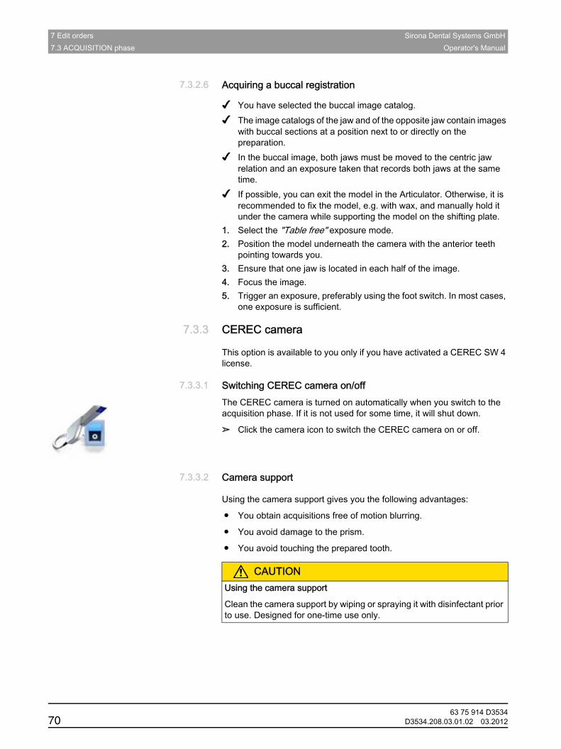
7 Edit orders Sirona Dental Systems GmbH7.3 ACQUISITION phase Operator's Manual
7.3.2.6 Acquiring a buccal registrationAcquiring a buccal registration
✔ You have selected the buccal image catalog.✔ The image catalogs of the jaw and of the opposite jaw contain images
with buccal sections at a position next to or directly on the preparation.
✔ In the buccal image, both jaws must be moved to the centric jaw relation and an exposure taken that records both jaws at the same time.
✔ If possible, you can exit the model in the Articulator. Otherwise, it is recommended to fix the model, e.g. with wax, and manually hold it under the camera while supporting the model on the shifting plate.
1. Select the "Table free" exposure mode.2. Position the model underneath the camera with the anterior teeth
pointing towards you.3. Ensure that one jaw is located in each half of the image.4. Focus the image.5. Trigger an exposure, preferably using the foot switch. In most cases,
one exposure is sufficient.
7.3.3 CEREC cameraCEREC camera
This option is available to you only if you have activated a CEREC SW 4 license.
7.3.3.1 Switching CEREC camera on/offSwitching CEREC camera on/offThe CEREC camera is turned on automatically when you switch to the acquisition phase. If it is not used for some time, it will shut down.
➢ Click the camera icon to switch the CEREC camera on or off.
7.3.3.2 Camera supportCamera support
Using the camera support gives you the following advantages:
● You obtain acquisitions free of motion blurring.
● You avoid damage to the prism.
● You avoid touching the prepared tooth.
CAUTIONUsing the camera support
Clean the camera support by wiping or spraying it with disinfectant prior to use. Designed for one-time use only.
63 75 914 D353470 D3534.208.03.01.02 03.2012
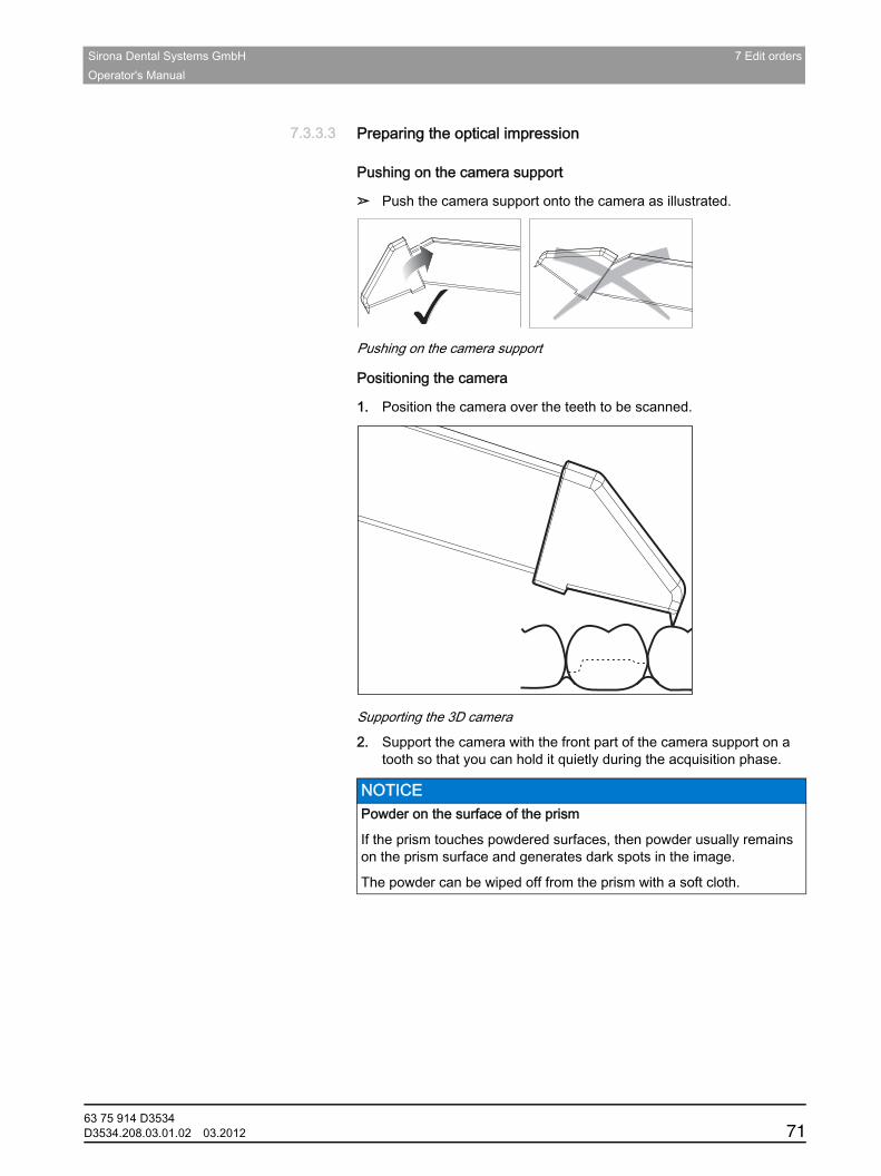
Sirona Dental Systems GmbH 7 Edit ordersOperator's Manual
båÖäáëÜ
7.3.3.3 Preparing the optical impressionPreparing the optical impression
Pushing on the camera support
➢ Push the camera support onto the camera as illustrated.
Pushing on the camera support
Positioning the camera
1. Position the camera over the teeth to be scanned.
Supporting the 3D camera
2. Support the camera with the front part of the camera support on a tooth so that you can hold it quietly during the acquisition phase.
NOTICE Powder on the surface of the prism
If the prism touches powdered surfaces, then powder usually remains on the prism surface and generates dark spots in the image.
The powder can be wiped off from the prism with a soft cloth.
63 75 914 D3534D3534.208.03.01.02 03.2012 71
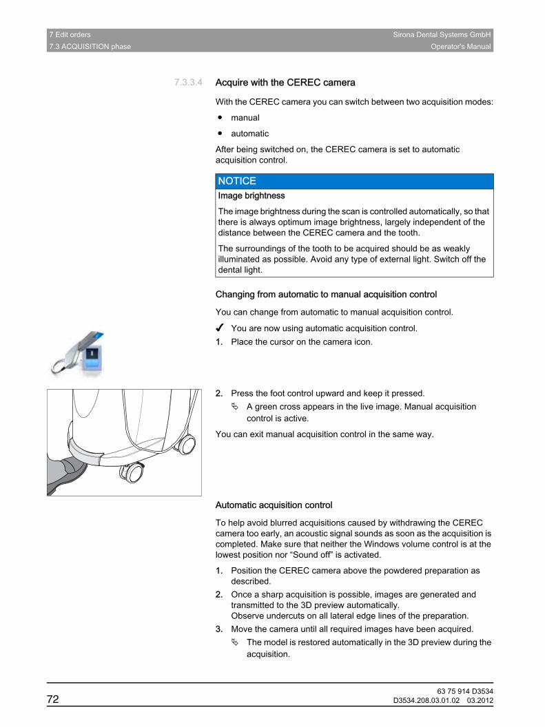
7 Edit orders Sirona Dental Systems GmbH7.3 ACQUISITION phase Operator's Manual
7.3.3.4 Acquire with the CEREC cameraAcquire with the CEREC cameraGeneral
With the CEREC camera you can switch between two acquisition modes:
● manual
● automatic
After being switched on, the CEREC camera is set to automatic acquisition control.
Changing from automatic to manual acquisition control
Changing from automatic to manual acquisition control
You can change from automatic to manual acquisition control.
✔ You are now using automatic acquisition control.1. Place the cursor on the camera icon.
2. Press the foot control upward and keep it pressed.A green cross appears in the live image. Manual acquisition control is active.
You can exit manual acquisition control in the same way.Automatic acquisition control
Automatic acquisition control
To help avoid blurred acquisitions caused by withdrawing the CEREC camera too early, an acoustic signal sounds as soon as the acquisition is completed. Make sure that neither the Windows volume control is at the lowest position nor “Sound off” is activated.
1. Position the CEREC camera above the powdered preparation as described.
2. Once a sharp acquisition is possible, images are generated and transmitted to the 3D preview automatically.Observe undercuts on all lateral edge lines of the preparation.
3. Move the camera until all required images have been acquired.The model is restored automatically in the 3D preview during the acquisition.
NOTICE Image brightness
The image brightness during the scan is controlled automatically, so that there is always optimum image brightness, largely independent of the distance between the CEREC camera and the tooth.
The surroundings of the tooth to be acquired should be as weakly illuminated as possible. Avoid any type of external light. Switch off the dental light.
63 75 914 D353472 D3534.208.03.01.02 03.2012
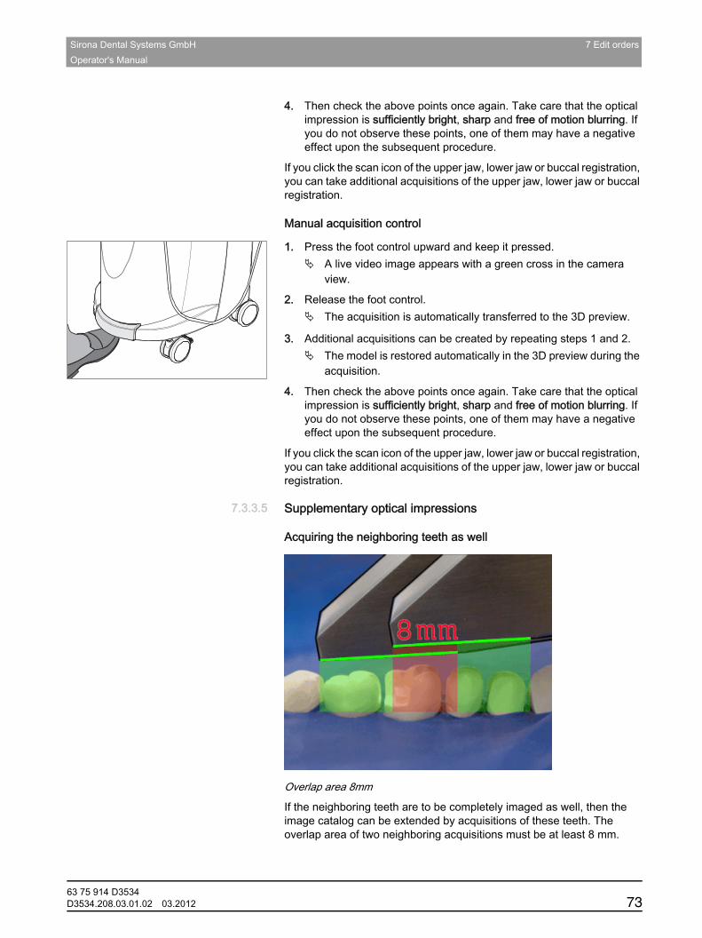
Sirona Dental Systems GmbH 7 Edit ordersOperator's Manual
båÖäáëÜ
4. Then check the above points once again. Take care that the optical impression is sufficiently bright, sharp and free of motion blurring. If you do not observe these points, one of them may have a negative effect upon the subsequent procedure.
If you click the scan icon of the upper jaw, lower jaw or buccal registration, you can take additional acquisitions of the upper jaw, lower jaw or buccal registration.Manual acquisition control
Manual acquisition control
1. Press the foot control upward and keep it pressed.A live video image appears with a green cross in the camera view.
2. Release the foot control.The acquisition is automatically transferred to the 3D preview.
3. Additional acquisitions can be created by repeating steps 1 and 2.The model is restored automatically in the 3D preview during the acquisition.
4. Then check the above points once again. Take care that the optical impression is sufficiently bright, sharp and free of motion blurring. If you do not observe these points, one of them may have a negative effect upon the subsequent procedure.
If you click the scan icon of the upper jaw, lower jaw or buccal registration, you can take additional acquisitions of the upper jaw, lower jaw or buccal registration.
7.3.3.5 Supplementary optical impressionsSupplementary optical impressions
Acquiring the neighboring teeth as well
Overlap area 8mm
If the neighboring teeth are to be completely imaged as well, then the image catalog can be extended by acquisitions of these teeth. The overlap area of two neighboring acquisitions must be at least 8 mm.
63 75 914 D3534D3534.208.03.01.02 03.2012 73
7 Edit orders Sirona Dental Systems GmbH7.3 ACQUISITION phase Operator's Manual
7.3.3.6 Optical impressions for quadrant restorationOptical impressions for quadrant restoration
For quadrant restoration it is recommended to acquire the prepared teeth as well as an unprepared neighboring tooth in each case. It can be covered by capturing several supplementary optical impressions.
7.3.3.7 Acquiring end teethAcquiring end teeth
End tooth at the distal margin
When end teeth are restored, the end tooth should lie at the distal margin of the image field.
7.3.3.8 Acquiring an impressionAcquiring an impression
Preparing an impression
✔ In certain circumstances, the impression must be cut free somewhat, so that the definition of the image of the CEREC camera is sufficient.
➢ If scannable silicon is not used, provide the area to be acquired with a matt finish to prevent reflections. For this purpose, use CEREC Optispray.
Acquiring an impression
1. Click on the icon of the desired image catalog.2. Open the image catalog.3. Click on the "Advanced" button.4. Click on the "Impression Scan" button.5. Start the acquisition procedure.
In the 3D preview, the model is displayed on both sides. The model preview is displayed in yellow, whereas the preview of the casting itself is shown in green.
As long as "Impression Scan" mode is active, acquisitions are inverted while creating the virtual model. "Impression Scan" mode is available for all image catalogs.
The various catalogs do not need to be acquired in the same mode.
7.3.4 3D Preview3D PreviewDescription
In the default setting, the data are displayed from the occlusal direction in the 3D preview.
You can freely select the viewing direction of the virtual model in the 3D preview window by using the mouse.Rotating a 3D preview
Rotating a 3D preview
1. Click on the 3D preview with the left mouse button and hold it down.2. Move the mouse.
The 3D preview is rotated.
63 75 914 D353474 D3534.208.03.01.02 03.2012
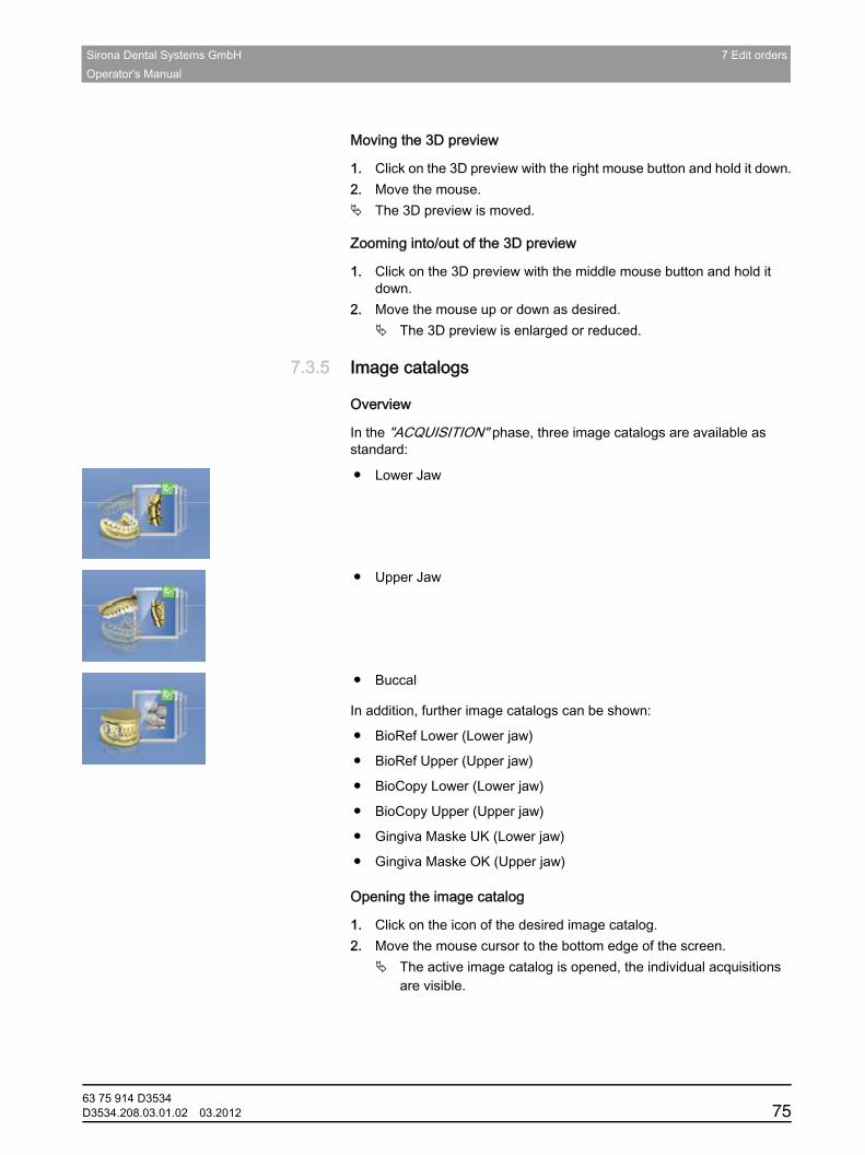
Sirona Dental Systems GmbH 7 Edit ordersOperator's Manual
båÖäáëÜ
Moving the 3D preview
Moving the 3D preview
1. Click on the 3D preview with the right mouse button and hold it down.2. Move the mouse.
The 3D preview is moved.Zooming into/out of the 3D preview
Zooming into/out of the 3D preview
1. Click on the 3D preview with the middle mouse button and hold it down.
2. Move the mouse up or down as desired.The 3D preview is enlarged or reduced.
7.3.5 Image catalogs Image catalogs
Overview
In the "ACQUISITION" phase, three image catalogs are available as standard:
● Lower Jaw
● Upper Jaw
● BuccalAdditional image catalogs
In addition, further image catalogs can be shown:
● BioRef Lower (Lower jaw)
● BioRef Upper (Upper jaw)
● BioCopy Lower (Lower jaw)
● BioCopy Upper (Upper jaw)
● Gingiva Maske UK (Lower jaw)
● Gingiva Maske OK (Upper jaw)Opening the image catalog
Opening the image catalog
1. Click on the icon of the desired image catalog.2. Move the mouse cursor to the bottom edge of the screen.
The active image catalog is opened, the individual acquisitions are visible.
63 75 914 D3534D3534.208.03.01.02 03.2012 75
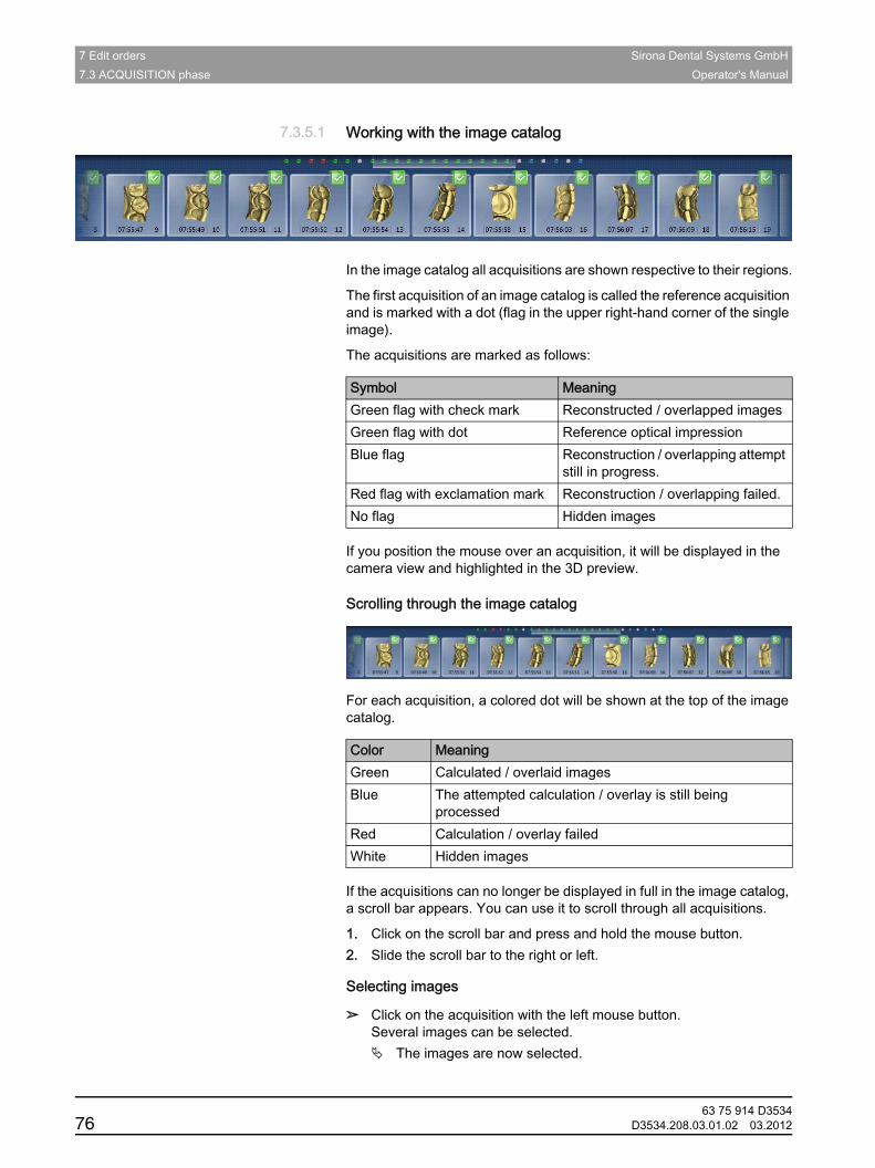
7 Edit orders Sirona Dental Systems GmbH7.3 ACQUISITION phase Operator's Manual
7.3.5.1 Working with the image catalogWorking with the image catalog
In the image catalog all acquisitions are shown respective to their regions.
The first acquisition of an image catalog is called the reference acquisition and is marked with a dot (flag in the upper right-hand corner of the single image).
The acquisitions are marked as follows:
If you position the mouse over an acquisition, it will be displayed in the camera view and highlighted in the 3D preview.Scrolling through the image catalog
Scrolling through the image catalog
For each acquisition, a colored dot will be shown at the top of the image catalog.
If the acquisitions can no longer be displayed in full in the image catalog, a scroll bar appears. You can use it to scroll through all acquisitions.
1. Click on the scroll bar and press and hold the mouse button.2. Slide the scroll bar to the right or left.Selecting images
Selecting images
➢ Click on the acquisition with the left mouse button.Several images can be selected.
The images are now selected.
Symbol MeaningGreen flag with check mark Reconstructed / overlapped imagesGreen flag with dot Reference optical impressionBlue flag Reconstruction / overlapping attempt
still in progress.Red flag with exclamation mark Reconstruction / overlapping failed.No flag Hidden images
Color MeaningGreen Calculated / overlaid imagesBlue The attempted calculation / overlay is still being
processedRed Calculation / overlay failedWhite Hidden images
63 75 914 D353476 D3534.208.03.01.02 03.2012
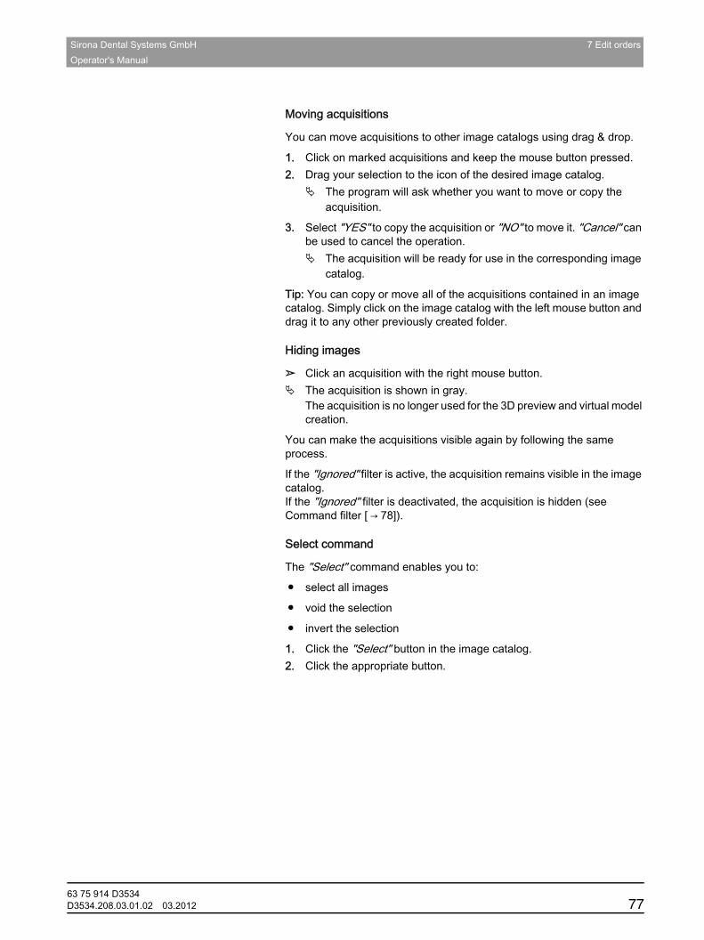
Sirona Dental Systems GmbH 7 Edit ordersOperator's Manual
båÖäáëÜ
Moving acquisitions
Moving acquisitions
You can move acquisitions to other image catalogs using drag & drop.
1. Click on marked acquisitions and keep the mouse button pressed.2. Drag your selection to the icon of the desired image catalog.
The program will ask whether you want to move or copy the acquisition.
3. Select "YES" to copy the acquisition or "NO" to move it. "Cancel" can be used to cancel the operation.
The acquisition will be ready for use in the corresponding image catalog.
Tip: You can copy or move all of the acquisitions contained in an image catalog. Simply click on the image catalog with the left mouse button and drag it to any other previously created folder.Hiding images
Hiding images
➢ Click an acquisition with the right mouse button.The acquisition is shown in gray.The acquisition is no longer used for the 3D preview and virtual model creation.
You can make the acquisitions visible again by following the same process.
If the "Ignored" filter is active, the acquisition remains visible in the image catalog.If the "Ignored" filter is deactivated, the acquisition is hidden (see Command filter [ → 78]).Select command
Select command
The "Select" command enables you to:
● select all images
● void the selection
● invert the selection
1. Click the "Select" button in the image catalog.2. Click the appropriate button.Edit command
63 75 914 D3534D3534.208.03.01.02 03.2012 77
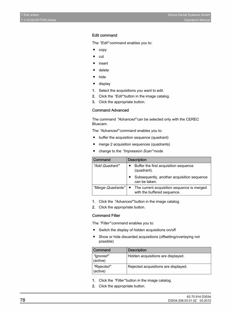
7 Edit orders Sirona Dental Systems GmbH7.3 ACQUISITION phase Operator's Manual
Edit command
The "Edit" command enables you to:
● copy
● cut
● insert
● delete
● hide
● display
1. Select the acquisitions you want to edit.2. Click the "Edit" button in the image catalog.3. Click the appropriate button.Advanced command
Command AdvancedBluecam only
The command "Advanced" can be selected only with the CEREC Bluecam.
The "Advanced" command enables you to:
● buffer the acquisition sequence (quadrant)
● merge 2 acquisition sequences (quadrants)
● change to the "Impression Scan" mode
1. Click the "Advanced" button in the image catalog.2. Click the appropriate button.Filter command
Command Filter
The "Filter" command enables you to:
● Switch the display of hidden acquisitions on/off
● Show or hide discarded acquisitions (offsetting/overlaying not possible)
1. Click the "Filter" button in the image catalog.2. Click the appropriate button.
Command Description"Add Quadrant" ● Buffer the first acquisition sequence
(quadrant).
● Subsequently, another acquisition sequence can be taken.
"Merge Quadrants" ● The current acquisition sequence is merged with the buffered sequence.
Command Description"Ignored" (active)
Hidden acquisitions are displayed.
"Rejected" (active)
Rejected acquisitions are displayed.
63 75 914 D353478 D3534.208.03.01.02 03.2012
Sirona Dental Systems GmbH 7 Edit ordersOperator's Manual
båÖäáëÜ
7.3.5.2 Adding image catalogsAdding image catalogsUsing the "Add Catalog" button, you can create additional image catalogs.Instructions
1. Click on the "Add Catalog" button.The possible image catalogs are displayed.
2. Click on the required image catalog.The image catalog is displayed next to the standard image catalogs.
7.3.5.3 Recycle binRecycle bin
Removing acquisitions
1. Select the acquisitions you want to remove.2. Click on the "Edit" button.3. Click on the "Delete" button.or
➢ Grab the image with your mouse and move it using drag & drop to the recycle bin.
The acquisition is sent to the recycle bin.
Tip: You can move the last acquisition to the recycle bin by right-clicking the image catalog icon.Opening the recycle bin
Opening the recycle bin
In the recycle bin, you will see the acquisitions removed from the currently active image catalog.
1. Click on the icon of the image catalog, for which you wish to open the recycle bin.
2. Click on the icon of the recycle bin.The recycle bin for the active image catalog is displayed.
Reusing acquisitions from the recycle bin
Reusing acquisitions from the recycle bin
➢ Grab the image with your mouse and move it using drag & drop to the desired folder.
Tip: If you show/hide acquisitions in the recycle bin, they will be automatically moved back to the image catalog.
63 75 914 D3534D3534.208.03.01.02 03.2012 79
7 Edit orders Sirona Dental Systems GmbH7.4 MODEL phase Operator's Manual
7.3.6 Finishing the phaseFinishing the phaseFinishing the acquisition phase
✔ All necessary acquisitions are available (jaw, possibly opposing jaw, and buccal bite acquisition).
✔ The "MODEL" phase is can be selected.➢ Click on the "MODEL" phase.or
➢ Click on the double arrow.
The program switches over to the "MODEL" phase.
7.4 MODEL phaseMODEL phase
In the "MODEL" phase, the virtual models are reconstructed based on the acquired image catalogs.
If you would like to edit the model, change to the "Edit Model" step.
The "Edit Model", "Bite Registration" and "Set Model Axis" refer to the entire model (upper and lower jaw).All other steps in the "MODEL" phase refer to the restoration currently selected. These steps must be performed individually for each restoration.
7.4.1 Editing the modelEditing the modelGeneral information on CEREC/inLab SW 4
In the "Edit Model" step, you can work with the following tools:
● Form
● Cut
● Replace
● Reset
The use of the individual tools is described in the section "Page palette".
7.4.2 Buccal registrationBuccal registration
In this step, you see the virtual models of the jaw, opposing jaw, and the buccal acquisition. The buccal acquisition is placed in the center between the lower jaw and upper jaw.General
In the "Bite Registration" step, you can work with the following tools:
● Drag Buccal
● Flip Buccal Impression
The use of the individual tools is described in the section Page palette .
For further information on the "Flip Buccal Impression" function, see the section Buccal registration [ → 82].Rotating models
63 75 914 D353480 D3534.208.03.01.02 03.2012

Sirona Dental Systems GmbH 7 Edit ordersOperator's Manual
båÖäáëÜ
Rotating the lower and upper jaw
➢ Click in the blue area with the left mouse button and hold the button down.
The lower jaw and upper jaw can be rotated about the vertical axis simultaneously.
➢ Click on the lower jaw or upper jaw with the left mouse button and hold the button down.
The jaws can be freely rotated individually.Registration
Registering the buccal acquisition on the lower jaw and upper jaw
1. Rotate both models so that you can see the overlap area of the buccal acquisition and of the upper jaw and lower jaw.
2. Now drag the buccal acquisition to the corresponding area of the upper jaw with the mouse and let go of the mouse button (drag & drop).
The buccal acquisition automatically registers itself on the upper jaw. If the registration was successful, this will be indicated by a "leopard pattern". If the registration was not successful, the buccal acquisition returns to its original position. In this case, you must repeat the drag&drop procedure in order to find a better correlation surface.
3. Now click on the buccal acquisition once again and drag it onto the appropriate area of the lower jaw (drag & drop).
If the registration was successful, this will be indicated by a "leopard pattern". If the registration was not successful, the buccal acquisition returns to its original position. In this case, you must repeat the drag&drop procedure in order to find a better correlation surface.
It is irrelevant whether you drag the buccal acquisition onto the lower jaw or onto the upper jaw first.
63 75 914 D3534D3534.208.03.01.02 03.2012 81
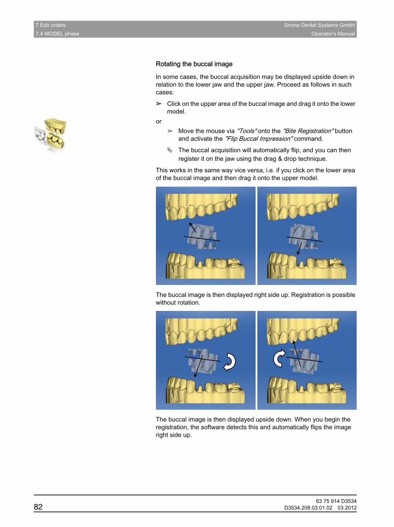
7 Edit orders Sirona Dental Systems GmbH7.4 MODEL phase Operator's Manual
Rotating the buccal image
Rotating the buccal image
In some cases, the buccal acquisition may be displayed upside down in relation to the lower jaw and the upper jaw. Proceed as follows in such cases:
➢ Click on the upper area of the buccal image and drag it onto the lower model.
or➢ Move the mouse via "Tools" onto the "Bite Registration" button
and activate the "Flip Buccal Impression" command.
The buccal acquisition will automatically flip, and you can then register it on the jaw using the drag & drop technique.
This works in the same way vice versa, i.e. if you click on the lower area of the buccal image and then drag it onto the upper model.
The buccal image is then displayed right side up. Registration is possible without rotation.
The buccal image is then displayed upside down. When you begin the registration, the software detects this and automatically flips the image right side up.Moving to the next step
63 75 914 D353482 D3534.208.03.01.02 03.2012
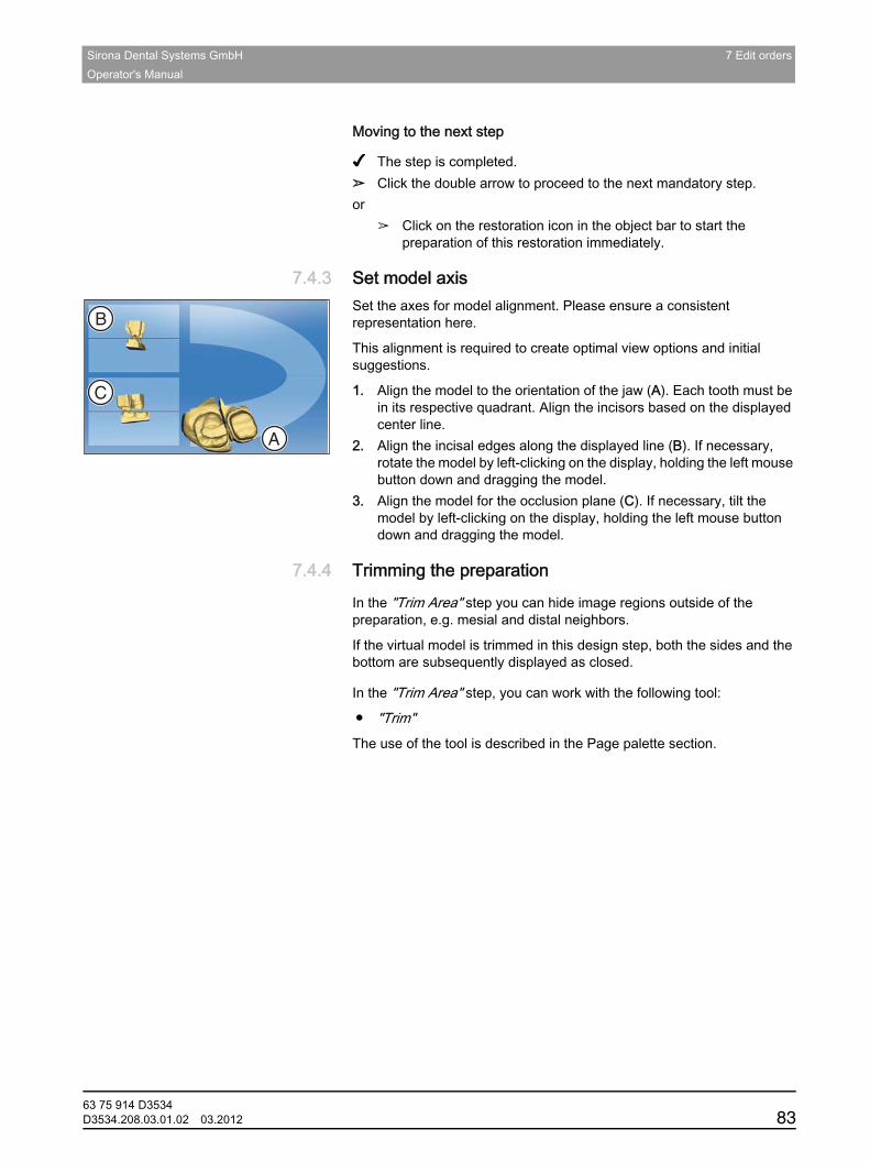
Sirona Dental Systems GmbH 7 Edit ordersOperator's Manual
båÖäáëÜ
Moving to the next step
✔ The step is completed.➢ Click the double arrow to proceed to the next mandatory step.or
➢ Click on the restoration icon in the object bar to start the preparation of this restoration immediately.
7.4.3 Set model axisSet model axisSet the axes for model alignment. Please ensure a consistent representation here.
This alignment is required to create optimal view options and initial suggestions.
1. Align the model to the orientation of the jaw (A). Each tooth must be in its respective quadrant. Align the incisors based on the displayed center line.
2. Align the incisal edges along the displayed line (B). If necessary, rotate the model by left-clicking on the display, holding the left mouse button down and dragging the model.
3. Align the model for the occlusion plane (C). If necessary, tilt the model by left-clicking on the display, holding the left mouse button down and dragging the model.
7.4.4 Trimming the preparationTrimming the preparationIntroduction
In the "Trim Area" step you can hide image regions outside of the preparation, e.g. mesial and distal neighbors.
If the virtual model is trimmed in this design step, both the sides and the bottom are subsequently displayed as closed.Tools
In the "Trim Area" step, you can work with the following tool:
● "Trim"The use of the tool is described in the Page palette section.Instructions
C
B
A
63 75 914 D3534D3534.208.03.01.02 03.2012 83
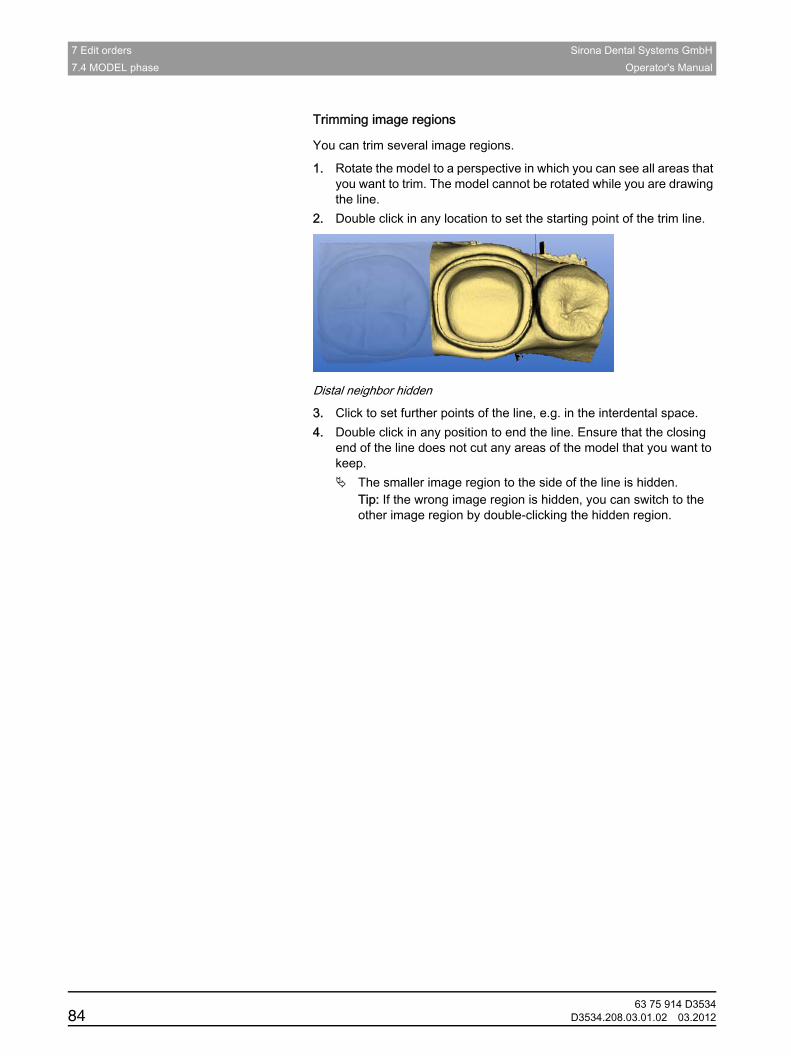
7 Edit orders Sirona Dental Systems GmbH7.4 MODEL phase Operator's Manual
Trimming image regions
You can trim several image regions.
1. Rotate the model to a perspective in which you can see all areas that you want to trim. The model cannot be rotated while you are drawing the line.
2. Double click in any location to set the starting point of the trim line.
Distal neighbor hidden
3. Click to set further points of the line, e.g. in the interdental space.4. Double click in any position to end the line. Ensure that the closing
end of the line does not cut any areas of the model that you want to keep.
The smaller image region to the side of the line is hidden.Tip: If the wrong image region is hidden, you can switch to the other image region by double-clicking the hidden region.
63 75 914 D353484 D3534.208.03.01.02 03.2012
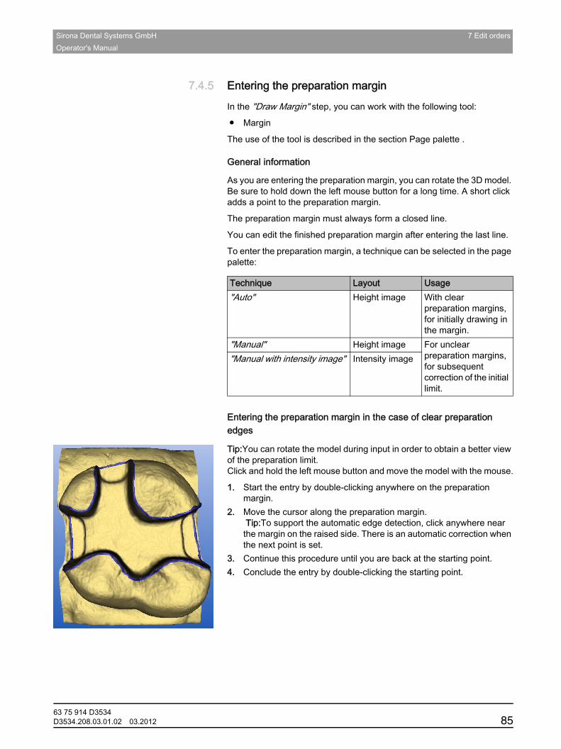
Sirona Dental Systems GmbH 7 Edit ordersOperator's Manual
båÖäáëÜ
7.4.5 Entering the preparation marginEntering the preparation marginGeneral
In the "Draw Margin" step, you can work with the following tool:
● Margin
The use of the tool is described in the section Page palette .General information
General information
As you are entering the preparation margin, you can rotate the 3D model. Be sure to hold down the left mouse button for a long time. A short click adds a point to the preparation margin.
The preparation margin must always form a closed line.
You can edit the finished preparation margin after entering the last line.
To enter the preparation margin, a technique can be selected in the page palette:
Entering preparation margin in the case of clear preparation margins
Entering the preparation margin in the case of clear preparation edges
Tip:You can rotate the model during input in order to obtain a better view of the preparation limit. Click and hold the left mouse button and move the model with the mouse.
1. Start the entry by double-clicking anywhere on the preparation margin.
2. Move the cursor along the preparation margin. Tip:To support the automatic edge detection, click anywhere near the margin on the raised side. There is an automatic correction when the next point is set.
3. Continue this procedure until you are back at the starting point.4. Conclude the entry by double-clicking the starting point.
Technique Layout Usage"Auto" Height image With clear
preparation margins, for initially drawing in the margin.
"Manual" Height image For unclear preparation margins, for subsequent correction of the initial limit.
"Manual with intensity image" Intensity image
63 75 914 D3534D3534.208.03.01.02 03.2012 85

7 Edit orders Sirona Dental Systems GmbH7.4 MODEL phase Operator's Manual
Entering a preparation margin with unclear edges
Entering the preparation margin in the case of blurred preparation edges
If you change to "Manual" in the page palette while entering the preparation margin, you can draw in the limit yourself.Be careful to set the points exactly on the edge and place them close together.
If you wish to see the intensity image in blurred situations, change to the page palette in "Manual with intensity image".Tip: The space bar can be used to switch back and forth between drawing modes.Moving to the next step
Moving to the next step
✔ The step is completed.➢ Continue with the preparation limits for the next restoration by clicking
on the desired restoration in the object bar.or
➢ Click on the next step.
7.4.6 Defining the insertion axisDefining the insertion axisCEREC SW 4 tools
In the "Define Insertion Axis" step, you can work with the following tools:
● Insertion Axis
The use of the individual tools is described in the section "Page palette".
63 75 914 D353486 D3534.208.03.01.02 03.2012
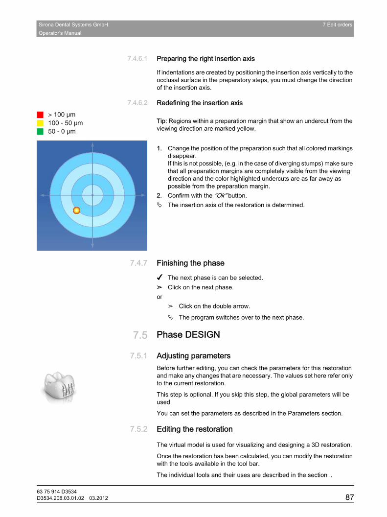
Sirona Dental Systems GmbH 7 Edit ordersOperator's Manual
båÖäáëÜ
7.4.6.1 Preparing the right insertion axisPreparing the right insertion axisReason
If indentations are created by positioning the insertion axis vertically to the occlusal surface in the preparatory steps, you must change the direction of the insertion axis.
7.4.6.2 Redefining the insertion axisRedefining the insertion axis
Tip
Tip: Regions within a preparation margin that show an undercut from the viewing direction are marked yellow.
inLab
1. Change the position of the preparation such that all colored markings disappear. If this is not possible, (e.g. in the case of diverging stumps) make sure that all preparation margins are completely visible from the viewing direction and the color highlighted undercuts are as far away as possible from the preparation margin.
2. Confirm with the "Ok" button.The insertion axis of the restoration is determined.
7.4.7 Finishing the phaseFinishing the phase
✔ The next phase is can be selected.➢ Click on the next phase.or
➢ Click on the double arrow.
The program switches over to the next phase.
7.5 Phase DESIGNPhase DESIGN
7.5.1 Adjusting parametersAdjusting parametersBefore further editing, you can check the parameters for this restoration and make any changes that are necessary. The values set here refer only to the current restoration.
This step is optional. If you skip this step, the global parameters will be used
You can set the parameters as described in the Parameters section.
7.5.2 Editing the restorationEditing the restoration
The virtual model is used for visualizing and designing a 3D restoration.
Once the restoration has been calculated, you can modify the restoration with the tools available in the tool bar.
The individual tools and their uses are described in the section .
> 100 µm100 - 50 µm50 - 0 µm
63 75 914 D3534D3534.208.03.01.02 03.2012 87
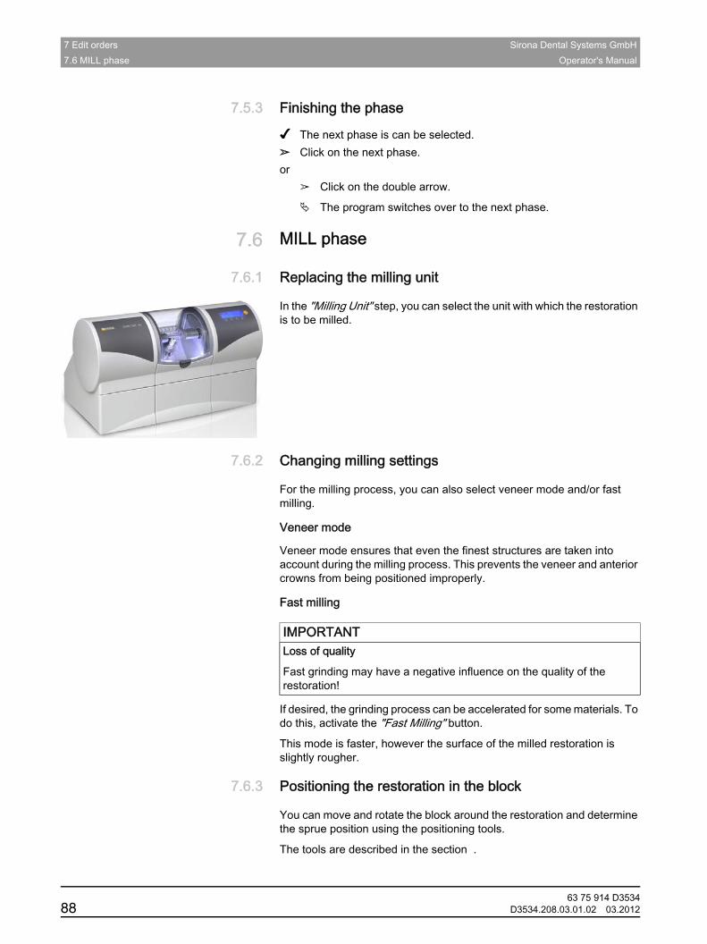
7 Edit orders Sirona Dental Systems GmbH7.6 MILL phase Operator's Manual
7.5.3 Finishing the phaseFinishing the phase
✔ The next phase is can be selected.➢ Click on the next phase.or
➢ Click on the double arrow.
The program switches over to the next phase.
7.6 MILL phaseMILL phase
7.6.1 Replacing the milling unitReplacing the milling unit
In the "Milling Unit" step, you can select the unit with which the restoration is to be milled.
7.6.2 Changing milling settingsChanging milling settings
For the milling process, you can also select veneer mode and/or fast milling.
Veneer mode
Veneer mode ensures that even the finest structures are taken into account during the milling process. This prevents the veneer and anterior crowns from being positioned improperly.
Fast milling
If desired, the grinding process can be accelerated for some materials. To do this, activate the "Fast Milling" button.
This mode is faster, however the surface of the milled restoration is slightly rougher.
7.6.3 Positioning the restoration in the blockPositioning the restoration in the block
You can move and rotate the block around the restoration and determine the sprue position using the positioning tools.
The tools are described in the section .
IMPORTANTLoss of quality
Fast grinding may have a negative influence on the quality of the restoration!
63 75 914 D353488 D3534.208.03.01.02 03.2012
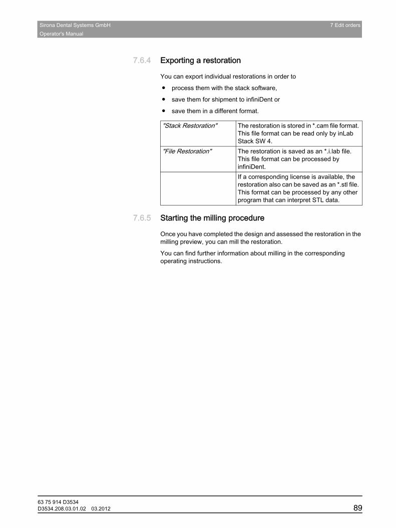
Sirona Dental Systems GmbH 7 Edit ordersOperator's Manual
båÖäáëÜ
7.6.4 Exporting a restorationExporting a restoration
You can export individual restorations in order to
● process them with the stack software,
● save them for shipment to infiniDent or
● save them in a different format.
7.6.5 Starting the milling procedureStarting the milling procedure
Once you have completed the design and assessed the restoration in the milling preview, you can mill the restoration.
You can find further information about milling in the corresponding operating instructions.
"Stack Restoration" The restoration is stored in *.cam file format. This file format can be read only by inLab Stack SW 4.
"File Restoration" The restoration is saved as an *.i.lab file. This file format can be processed by infiniDent.If a corresponding license is available, the restoration also can be saved as an *.stl file. This format can be processed by any other program that can interpret STL data.
63 75 914 D3534D3534.208.03.01.02 03.2012 89
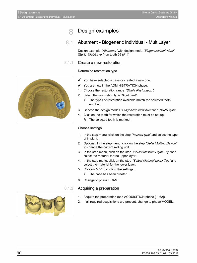
8 Design examples Sirona Dental Systems GmbH8.1 Abutment - Biogeneric individual - MultiLayer Operator's Manual
8 Design examplesDesign examples
8.1 Abutment - Biogeneric individual - MultiLayerAbutment - Biogeneric individual - MultiLayer
Design example "Abutment" with design mode "Biogeneric Individual" (Split: "MultiLayer") on tooth 26 (#14)
8.1.1 Create a new restorationCreate a new restoration
Determine restoration type
Instructions
✔ You have selected a case or created a new one.✔ You are now in the ADMINISTRATION phase.1. Choose the restoration range "Single Restoration".2. Select the restoration type "Abutment".
The types of restoration available match the selected tooth number.
3. Choose the design modes "Biogeneric Individual" and "MultiLayer".4. Click on the tooth for which the restoration must be set up.
The selected tooth is marked.Choose settings
Choose settingsInstructions
1. In the step menu, click on the step "Implant type" and select the type of implant.
2. Optional: In the step menu, click on the step "Select Milling Device" to change the current milling unit.
3. In the step menu, click on the step "Select Material Layer Top" and select the material for the upper layer.
4. In the step menu, click on the step "Select Material Layer Top" and select the material for the lower layer.
5. Click on "Ok" to confirm the settings.The case has been created.
6. Change to phase SCAN.
8.1.2 Acquiring a preparationAcquiring a preparation
Instructions
1. Acquire the preparation (see ACQUISITION phase [ → 62]).2. If all required acquisitions are present, change to phase MODEL.
63 75 914 D353490 D3534.208.03.01.02 03.2012
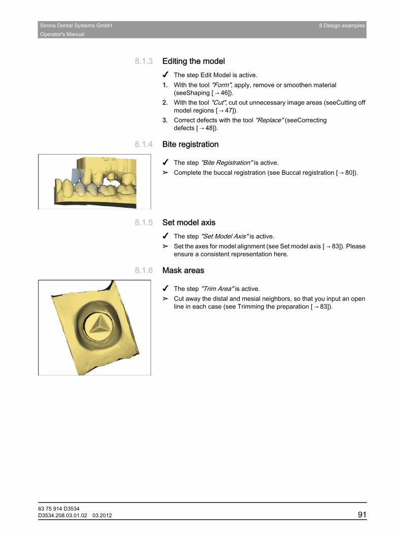
Sirona Dental Systems GmbH 8 Design examplesOperator's Manual
båÖäáëÜ
8.1.3 Editing the modelEditing the modelInstructions
✔ The step Edit Model is active.1. With the tool "Form", apply, remove or smoothen material
(seeShaping [ → 46]).2. With the tool "Cut", cut out unnecessary image areas (seeCutting off
model regions [ → 47]).3. Correct defects with the tool "Replace" (seeCorrecting
defects [ → 48]).
8.1.4 Bite registrationBite registration
Instructions
✔ The step "Bite Registration" is active.➢ Complete the buccal registration (see Buccal registration [ → 80]).
8.1.5 Set model axisSet model axisInstructions
✔ The step "Set Model Axis" is active.➢ Set the axes for model alignment (see Set model axis [ → 83]). Please
ensure a consistent representation here.
8.1.6 Mask areasMask areas
Instructions
✔ The step "Trim Area" is active.➢ Cut away the distal and mesial neighbors, so that you input an open
line in each case (see Trimming the preparation [ → 83]).
63 75 914 D3534D3534.208.03.01.02 03.2012 91
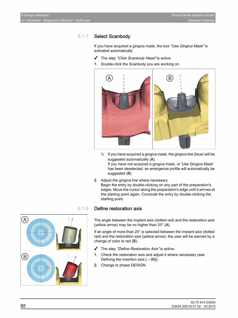
8 Design examples Sirona Dental Systems GmbH8.1 Abutment - Biogeneric individual - MultiLayer Operator's Manual
8.1.7 Select ScanbodySelect Scanbody
If you have acquired a gingiva mask, the tool "Use Gingiva Mask" is activated automatically.
✔ The step "Click Scanbody Head" is active.1. Double-click the Scanbody you are working on.
If you have acquired a gingiva mask, the gingiva line (blue) will be suggested automatically (A).If you have not acquired a gingiva mask, or 'Use Gingiva Mask' has been deselected, an emergence profile will automatically be suggested (B).
2. Adjust the gingiva line where necessary.Begin the entry by double-clicking on any part of the preparation's edges. Move the cursor along the preparation's edge until it arrives at the starting point again. Conclude the entry by double-clicking the starting point.
8.1.8 Define restoration axisDefine restoration axis
Change of color
The angle between the implant axis (dotted red) and the restoration axis (yellow arrow) may be no higher than 20° (A).
If an angle of more than 20° is selected between the implant axis (dotted red) and the restoration axis (yellow arrow), the user will be warned by a change of color to red (B).Instructions
✔ The step "Define Restoration Axis" is active.1. Check the restoration axis and adjust it where necessary (see
Defining the insertion axis [ → 86]).2. Change to phase DESIGN.
63 75 914 D353492 D3534.208.03.01.02 03.2012
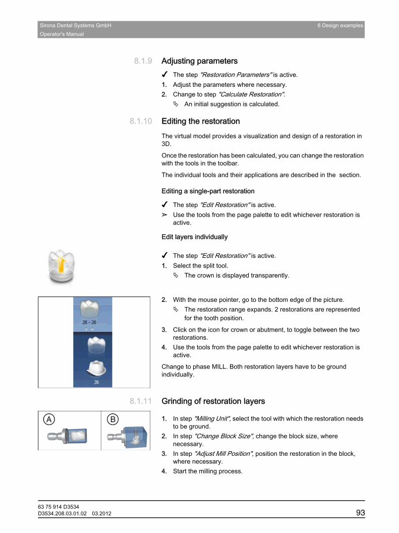
Sirona Dental Systems GmbH 8 Design examplesOperator's Manual
båÖäáëÜ
8.1.9 Adjusting parametersAdjusting parametersInstructions
✔ The step "Restoration Parameters" is active.1. Adjust the parameters where necessary.2. Change to step "Calculate Restoration".
An initial suggestion is calculated.
8.1.10 Editing the restorationEditing the restorationGeneral
The virtual model provides a visualization and design of a restoration in 3D.
Once the restoration has been calculated, you can change the restoration with the tools in the toolbar.
The individual tools and their applications are described in the section.Editing a single-part restoration
Editing a single-part restoration
✔ The step "Edit Restoration" is active.➢ Use the tools from the page palette to edit whichever restoration is
active.Edit layers individually
Edit layers individually
Split
✔ The step "Edit Restoration" is active.1. Select the split tool.
The crown is displayed transparently.
2. With the mouse pointer, go to the bottom edge of the picture.The restoration range expands. 2 restorations are represented for the tooth position.
3. Click on the icon for crown or abutment, to toggle between the two restorations.
4. Use the tools from the page palette to edit whichever restoration is active.
Change to phase MILL. Both restoration layers have to be ground individually.
8.1.11 Grinding of restoration layersGrinding of restoration layers
Instructions
1. In step "Milling Unit", select the tool with which the restoration needs to be ground.
2. In step "Change Block Size", change the block size, where necessary.
3. In step "Adjust Mill Position", position the restoration in the block, where necessary.
4. Start the milling process.
63 75 914 D3534D3534.208.03.01.02 03.2012 93
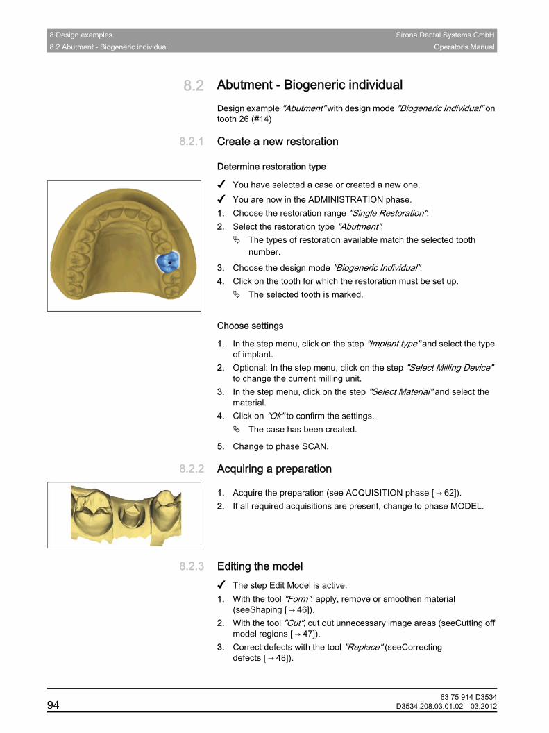
8 Design examples Sirona Dental Systems GmbH8.2 Abutment - Biogeneric individual Operator's Manual
8.2 Abutment - Biogeneric individualAbutment - Biogeneric individual
Design example "Abutment" with design mode "Biogeneric Individual" on tooth 26 (#14)
8.2.1 Create a new restorationCreate a new restoration
Determine restoration type
✔ You have selected a case or created a new one.✔ You are now in the ADMINISTRATION phase.1. Choose the restoration range "Single Restoration".2. Select the restoration type "Abutment".
The types of restoration available match the selected tooth number.
3. Choose the design mode "Biogeneric Individual".4. Click on the tooth for which the restoration must be set up.
The selected tooth is marked.
Choose settings
1. In the step menu, click on the step "Implant type" and select the type of implant.
2. Optional: In the step menu, click on the step "Select Milling Device" to change the current milling unit.
3. In the step menu, click on the step "Select Material" and select the material.
4. Click on "Ok" to confirm the settings.The case has been created.
5. Change to phase SCAN.
8.2.2 Acquiring a preparationAcquiring a preparation
Instructions
1. Acquire the preparation (see ACQUISITION phase [ → 62]).2. If all required acquisitions are present, change to phase MODEL.
8.2.3 Editing the modelEditing the modelInstructions
✔ The step Edit Model is active.1. With the tool "Form", apply, remove or smoothen material
(seeShaping [ → 46]).2. With the tool "Cut", cut out unnecessary image areas (seeCutting off
model regions [ → 47]).3. Correct defects with the tool "Replace" (seeCorrecting
defects [ → 48]).
63 75 914 D353494 D3534.208.03.01.02 03.2012
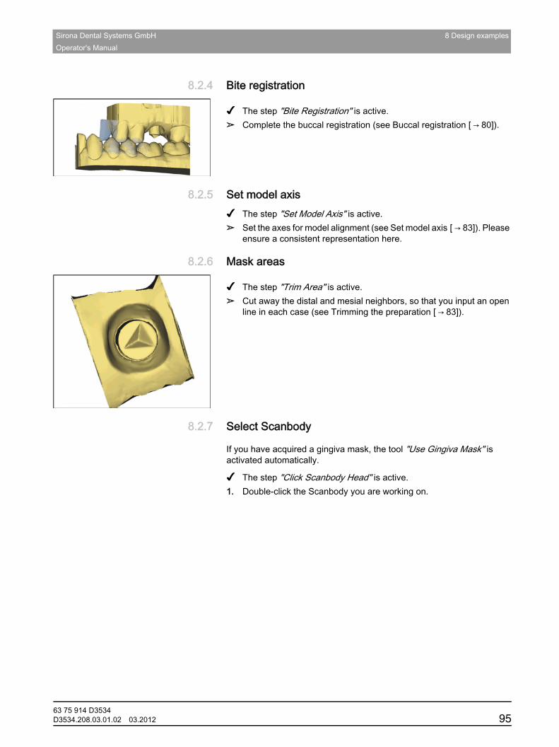
Sirona Dental Systems GmbH 8 Design examplesOperator's Manual
båÖäáëÜ
8.2.4 Bite registrationBite registration
Instructions
✔ The step "Bite Registration" is active.➢ Complete the buccal registration (see Buccal registration [ → 80]).
8.2.5 Set model axisSet model axisInstructions
✔ The step "Set Model Axis" is active.➢ Set the axes for model alignment (see Set model axis [ → 83]). Please
ensure a consistent representation here.
8.2.6 Mask areasMask areas
Instructions
✔ The step "Trim Area" is active.➢ Cut away the distal and mesial neighbors, so that you input an open
line in each case (see Trimming the preparation [ → 83]).
8.2.7 Select ScanbodySelect Scanbody
If you have acquired a gingiva mask, the tool "Use Gingiva Mask" is activated automatically.
✔ The step "Click Scanbody Head" is active.1. Double-click the Scanbody you are working on.
63 75 914 D3534D3534.208.03.01.02 03.2012 95
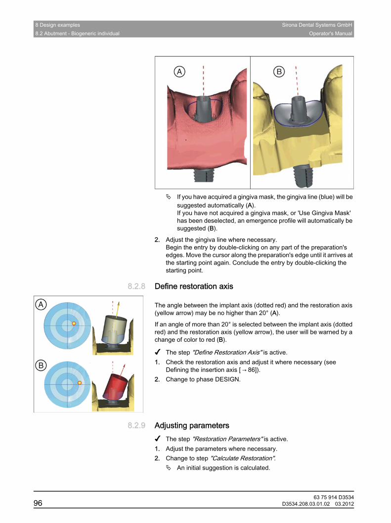
8 Design examples Sirona Dental Systems GmbH8.2 Abutment - Biogeneric individual Operator's Manual
If you have acquired a gingiva mask, the gingiva line (blue) will be suggested automatically (A).If you have not acquired a gingiva mask, or 'Use Gingiva Mask' has been deselected, an emergence profile will automatically be suggested (B).
2. Adjust the gingiva line where necessary.Begin the entry by double-clicking on any part of the preparation's edges. Move the cursor along the preparation's edge until it arrives at the starting point again. Conclude the entry by double-clicking the starting point.
8.2.8 Define restoration axisDefine restoration axis
Change of color
The angle between the implant axis (dotted red) and the restoration axis (yellow arrow) may be no higher than 20° (A).
If an angle of more than 20° is selected between the implant axis (dotted red) and the restoration axis (yellow arrow), the user will be warned by a change of color to red (B).Instructions
✔ The step "Define Restoration Axis" is active.1. Check the restoration axis and adjust it where necessary (see
Defining the insertion axis [ → 86]).2. Change to phase DESIGN.
8.2.9 Adjusting parametersAdjusting parametersInstructions
✔ The step "Restoration Parameters" is active.1. Adjust the parameters where necessary.2. Change to step "Calculate Restoration".
An initial suggestion is calculated.
63 75 914 D353496 D3534.208.03.01.02 03.2012
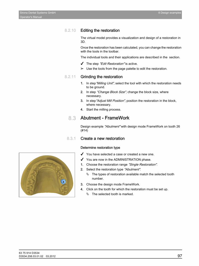
Sirona Dental Systems GmbH 8 Design examplesOperator's Manual
båÖäáëÜ
8.2.10 Editing the restorationEditing the restorationGeneral
The virtual model provides a visualization and design of a restoration in 3D.
Once the restoration has been calculated, you can change the restoration with the tools in the toolbar.
The individual tools and their applications are described in the section.Single parts
✔ The step "Edit Restoration" is active.➢ Use the tools from the page palette to edit the restoration.
8.2.11 Grinding the restorationGrinding the restorationInstructions
1. In step"Milling Unit", select the tool with which the restoration needs to be ground.
2. In step "Change Block Size", change the block size, where necessary.
3. In step"Adjust Mill Position", position the restoration in the block, where necessary.
4. Start the milling process.
8.3 Abutment - FrameWorkAbutment - FrameWork
Design example "Abutment" with design mode FrameWork on tooth 26 (#14)
8.3.1 Create a new restorationCreate a new restoration
Determine restoration type
✔ You have selected a case or created a new one.✔ You are now in the ADMINISTRATION phase.1. Choose the restoration range "Single Restoration".2. Select the restoration type "Abutment".
The types of restoration available match the selected tooth number.
3. Choose the design mode FrameWork.4. Click on the tooth for which the restoration must be set up.
The selected tooth is marked.
63 75 914 D3534D3534.208.03.01.02 03.2012 97
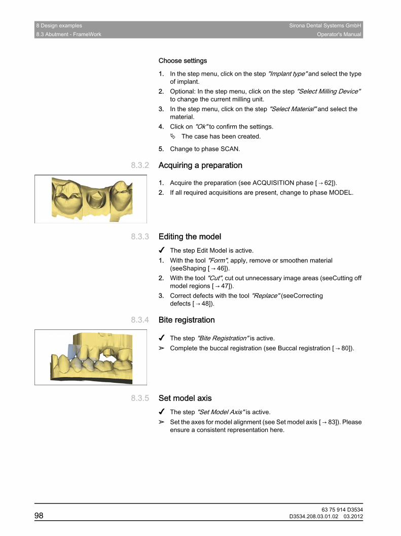
8 Design examples Sirona Dental Systems GmbH8.3 Abutment - FrameWork Operator's Manual
Choose settings
1. In the step menu, click on the step "Implant type" and select the type of implant.
2. Optional: In the step menu, click on the step "Select Milling Device" to change the current milling unit.
3. In the step menu, click on the step "Select Material" and select the material.
4. Click on "Ok" to confirm the settings.The case has been created.
5. Change to phase SCAN.
8.3.2 Acquiring a preparationAcquiring a preparation
Instructions
1. Acquire the preparation (see ACQUISITION phase [ → 62]).2. If all required acquisitions are present, change to phase MODEL.
8.3.3 Editing the modelEditing the modelInstructions
✔ The step Edit Model is active.1. With the tool "Form", apply, remove or smoothen material
(seeShaping [ → 46]).2. With the tool "Cut", cut out unnecessary image areas (seeCutting off
model regions [ → 47]).3. Correct defects with the tool "Replace" (seeCorrecting
defects [ → 48]).
8.3.4 Bite registrationBite registration
Instructions
✔ The step "Bite Registration" is active.➢ Complete the buccal registration (see Buccal registration [ → 80]).
8.3.5 Set model axisSet model axisInstructions
✔ The step "Set Model Axis" is active.➢ Set the axes for model alignment (see Set model axis [ → 83]). Please
ensure a consistent representation here.
63 75 914 D353498 D3534.208.03.01.02 03.2012

Sirona Dental Systems GmbH 8 Design examplesOperator's Manual
båÖäáëÜ
8.3.6 Mask areasMask areas
Instructions
✔ The step "Trim Area" is active.➢ Cut away the distal and mesial neighbors, so that you input an open
line in each case (see Trimming the preparation [ → 83]).
8.3.7 Select ScanbodySelect Scanbody
If you have acquired a gingiva mask, the tool "Use Gingiva Mask" is activated automatically.
✔ The step "Click Scanbody Head" is active.1. Double-click the Scanbody you are working on.
If you have acquired a gingiva mask, the gingiva line (blue) will be suggested automatically (A).If you have not acquired a gingiva mask, or 'Use Gingiva Mask' has been deselected, an emergence profile will automatically be suggested (B).
2. Adjust the gingiva line where necessary.Begin the entry by double-clicking on any part of the preparation's edges. Move the cursor along the preparation's edge until it arrives at the starting point again. Conclude the entry by double-clicking the starting point.
63 75 914 D3534D3534.208.03.01.02 03.2012 99
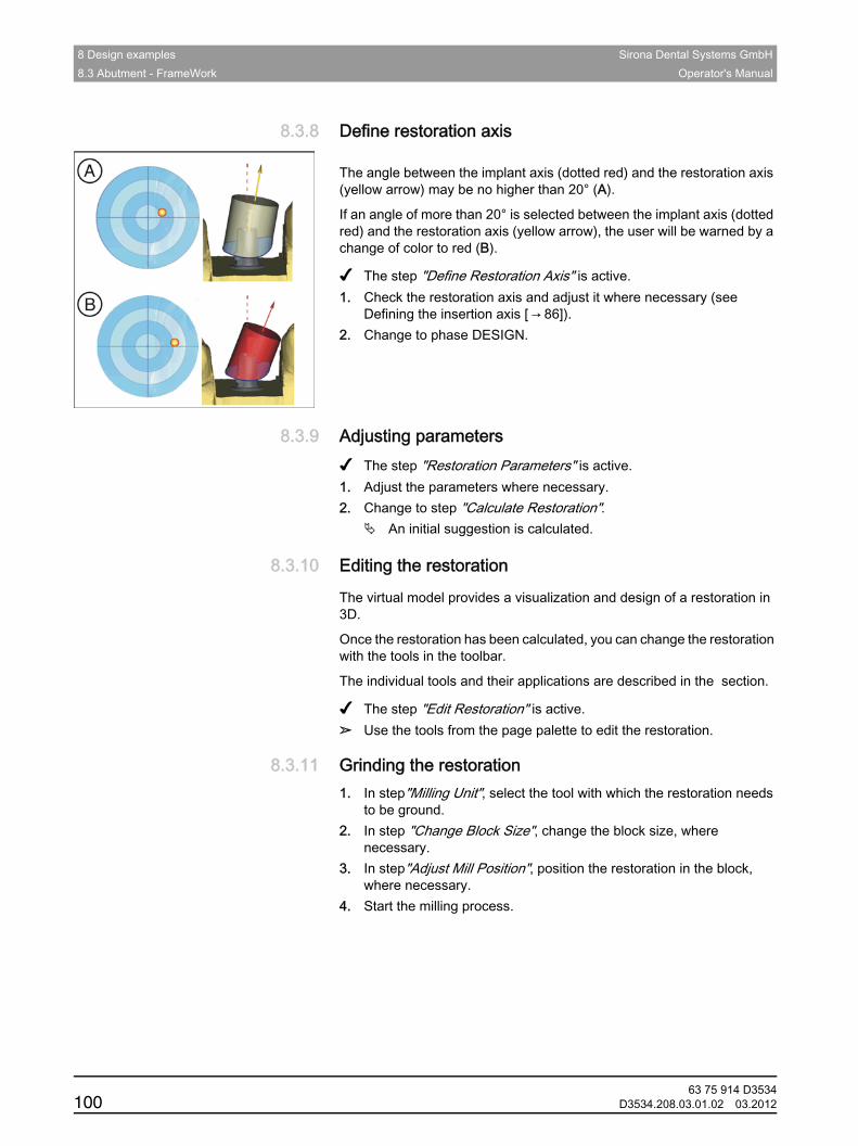
8 Design examples Sirona Dental Systems GmbH8.3 Abutment - FrameWork Operator's Manual
8.3.8 Define restoration axisDefine restoration axis
Change of color
The angle between the implant axis (dotted red) and the restoration axis (yellow arrow) may be no higher than 20° (A).
If an angle of more than 20° is selected between the implant axis (dotted red) and the restoration axis (yellow arrow), the user will be warned by a change of color to red (B).Instructions
✔ The step "Define Restoration Axis" is active.1. Check the restoration axis and adjust it where necessary (see
Defining the insertion axis [ → 86]).2. Change to phase DESIGN.
8.3.9 Adjusting parametersAdjusting parametersInstructions
✔ The step "Restoration Parameters" is active.1. Adjust the parameters where necessary.2. Change to step "Calculate Restoration".
An initial suggestion is calculated.
8.3.10 Editing the restorationEditing the restorationGeneral
The virtual model provides a visualization and design of a restoration in 3D.
Once the restoration has been calculated, you can change the restoration with the tools in the toolbar.
The individual tools and their applications are described in the section.Single parts
✔ The step "Edit Restoration" is active.➢ Use the tools from the page palette to edit the restoration.
8.3.11 Grinding the restorationGrinding the restorationInstructions
1. In step"Milling Unit", select the tool with which the restoration needs to be ground.
2. In step "Change Block Size", change the block size, where necessary.
3. In step"Adjust Mill Position", position the restoration in the block, where necessary.
4. Start the milling process.
63 75 914 D3534100 D3534.208.03.01.02 03.2012
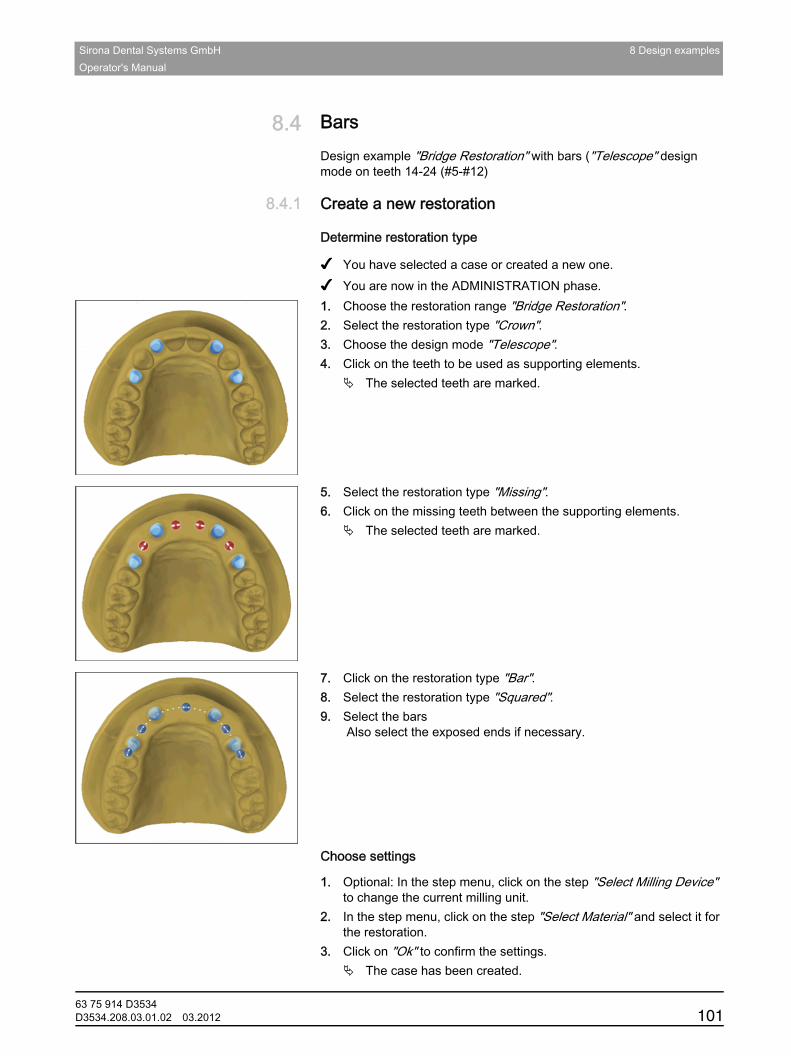
Sirona Dental Systems GmbH 8 Design examplesOperator's Manual
båÖäáëÜ
8.4 BarsBars
Design example "Bridge Restoration" with bars ("Telescope" design mode on teeth 14-24 (#5-#12)
8.4.1 Create a new restorationCreate a new restoration
Determine restoration type
✔ You have selected a case or created a new one.✔ You are now in the ADMINISTRATION phase.1. Choose the restoration range "Bridge Restoration".2. Select the restoration type "Crown".3. Choose the design mode "Telescope".4. Click on the teeth to be used as supporting elements.
The selected teeth are marked.
5. Select the restoration type "Missing".6. Click on the missing teeth between the supporting elements.
The selected teeth are marked.
7. Click on the restoration type "Bar".8. Select the restoration type "Squared".9. Select the bars
Also select the exposed ends if necessary.Choose settings
Choose settings
1. Optional: In the step menu, click on the step "Select Milling Device" to change the current milling unit.
2. In the step menu, click on the step "Select Material" and select it for the restoration.
3. Click on "Ok" to confirm the settings.The case has been created.
63 75 914 D3534D3534.208.03.01.02 03.2012 101
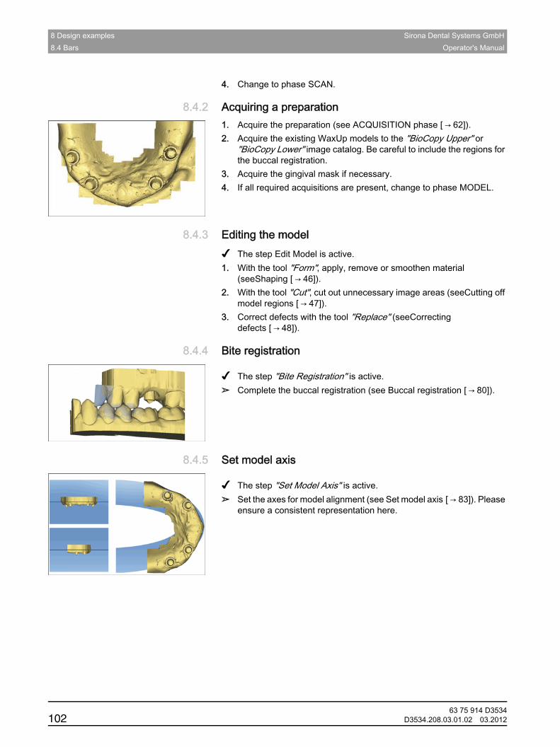
8 Design examples Sirona Dental Systems GmbH8.4 Bars Operator's Manual
4. Change to phase SCAN.
8.4.2 Acquiring a preparationAcquiring a preparation1. Acquire the preparation (see ACQUISITION phase [ → 62]).2. Acquire the existing WaxUp models to the "BioCopy Upper" or
"BioCopy Lower" image catalog. Be careful to include the regions for the buccal registration.
3. Acquire the gingival mask if necessary.4. If all required acquisitions are present, change to phase MODEL.
8.4.3 Editing the modelEditing the modelInstructions
✔ The step Edit Model is active.1. With the tool "Form", apply, remove or smoothen material
(seeShaping [ → 46]).2. With the tool "Cut", cut out unnecessary image areas (seeCutting off
model regions [ → 47]).3. Correct defects with the tool "Replace" (seeCorrecting
defects [ → 48]).
8.4.4 Bite registrationBite registration
Instructions
✔ The step "Bite Registration" is active.➢ Complete the buccal registration (see Buccal registration [ → 80]).
8.4.5 Set model axisSet model axis
Instructions
✔ The step "Set Model Axis" is active.➢ Set the axes for model alignment (see Set model axis [ → 83]). Please
ensure a consistent representation here.
63 75 914 D3534102 D3534.208.03.01.02 03.2012
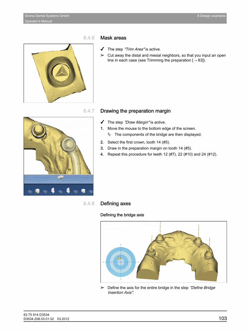
Sirona Dental Systems GmbH 8 Design examplesOperator's Manual
båÖäáëÜ
8.4.6 Mask areasMask areas
Instructions
✔ The step "Trim Area" is active.➢ Cut away the distal and mesial neighbors, so that you input an open
line in each case (see Trimming the preparation [ → 83]).
8.4.7 Drawing the preparation marginDrawing the preparation margin
Instructions
✔ The step "Draw Margin" is active.1. Move the mouse to the bottom edge of the screen.
The components of the bridge are then displayed.
2. Select the first crown, tooth 14 (#5).3. Draw in the preparation margin on tooth 14 (#5).4. Repeat this procedure for teeth 12 (#7), 22 (#10) and 24 (#12).
8.4.8 Defining axesDefining axes
Defining the bridge axis
➢ Define the axis for the entire bridge in the step "Define Bridge Insertion Axis".
63 75 914 D3534D3534.208.03.01.02 03.2012 103
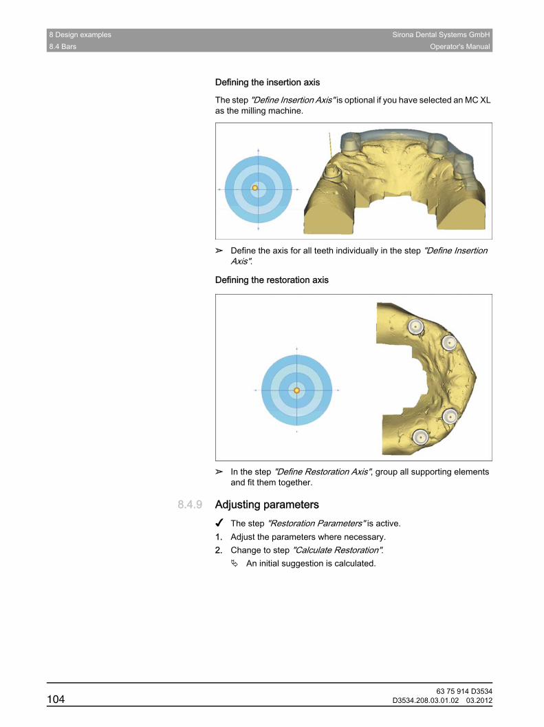
8 Design examples Sirona Dental Systems GmbH8.4 Bars Operator's Manual
Defining the insertion axis
The step "Define Insertion Axis" is optional if you have selected an MC XL as the milling machine.
➢ Define the axis for all teeth individually in the step "Define Insertion Axis".
Defining the restoration axis
➢ In the step "Define Restoration Axis", group all supporting elements and fit them together.
8.4.9 Adjusting parametersAdjusting parametersInstructions
✔ The step "Restoration Parameters" is active.1. Adjust the parameters where necessary.2. Change to step "Calculate Restoration".
An initial suggestion is calculated.
63 75 914 D3534104 D3534.208.03.01.02 03.2012
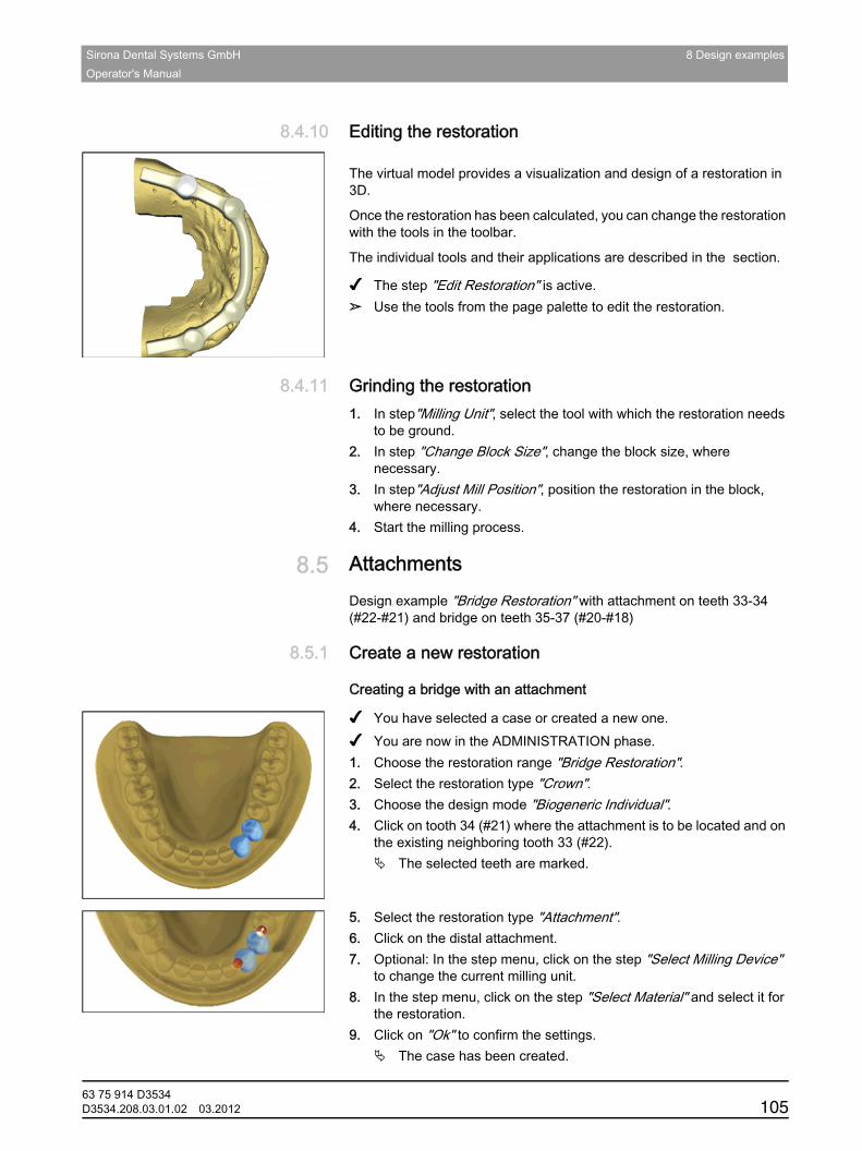
Sirona Dental Systems GmbH 8 Design examplesOperator's Manual
båÖäáëÜ
8.4.10 Editing the restorationEditing the restoration
General
The virtual model provides a visualization and design of a restoration in 3D.
Once the restoration has been calculated, you can change the restoration with the tools in the toolbar.
The individual tools and their applications are described in the section.Single parts
✔ The step "Edit Restoration" is active.➢ Use the tools from the page palette to edit the restoration.
8.4.11 Grinding the restorationGrinding the restorationInstructions
1. In step"Milling Unit", select the tool with which the restoration needs to be ground.
2. In step "Change Block Size", change the block size, where necessary.
3. In step"Adjust Mill Position", position the restoration in the block, where necessary.
4. Start the milling process.
8.5 AttachmentsAttachments
Design example "Bridge Restoration" with attachment on teeth 33-34 (#22-#21) and bridge on teeth 35-37 (#20-#18)
8.5.1 Create a new restorationCreate a new restoration
Creating a bridge with an attachment
✔ You have selected a case or created a new one.✔ You are now in the ADMINISTRATION phase.1. Choose the restoration range "Bridge Restoration".2. Select the restoration type "Crown".3. Choose the design mode "Biogeneric Individual".4. Click on tooth 34 (#21) where the attachment is to be located and on
the existing neighboring tooth 33 (#22).The selected teeth are marked.
5. Select the restoration type "Attachment".6. Click on the distal attachment.7. Optional: In the step menu, click on the step "Select Milling Device"
to change the current milling unit.8. In the step menu, click on the step "Select Material" and select it for
the restoration.9. Click on "Ok" to confirm the settings.
The case has been created.
63 75 914 D3534D3534.208.03.01.02 03.2012 105
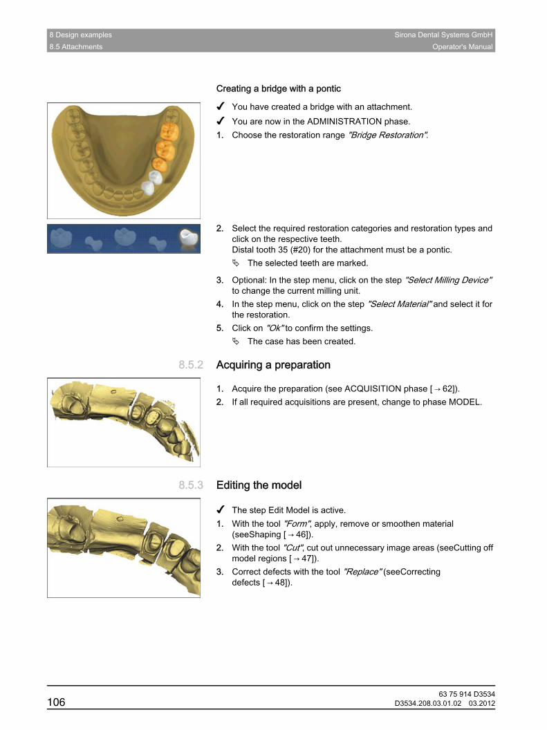
8 Design examples Sirona Dental Systems GmbH8.5 Attachments Operator's Manual
Bridge with pontic
Creating a bridge with a pontic
✔ You have created a bridge with an attachment.✔ You are now in the ADMINISTRATION phase.1. Choose the restoration range "Bridge Restoration".
2. Select the required restoration categories and restoration types and click on the respective teeth.Distal tooth 35 (#20) for the attachment must be a pontic.
The selected teeth are marked.
3. Optional: In the step menu, click on the step "Select Milling Device" to change the current milling unit.
4. In the step menu, click on the step "Select Material" and select it for the restoration.
5. Click on "Ok" to confirm the settings.The case has been created.
8.5.2 Acquiring a preparationAcquiring a preparation
Instructions
1. Acquire the preparation (see ACQUISITION phase [ → 62]).2. If all required acquisitions are present, change to phase MODEL.
8.5.3 Editing the modelEditing the model
Instructions
✔ The step Edit Model is active.1. With the tool "Form", apply, remove or smoothen material
(seeShaping [ → 46]).2. With the tool "Cut", cut out unnecessary image areas (seeCutting off
model regions [ → 47]).3. Correct defects with the tool "Replace" (seeCorrecting
defects [ → 48]).
63 75 914 D3534106 D3534.208.03.01.02 03.2012
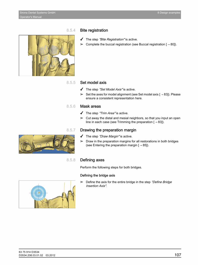
Sirona Dental Systems GmbH 8 Design examplesOperator's Manual
båÖäáëÜ
8.5.4 Bite registrationBite registration
Instructions
✔ The step "Bite Registration" is active.➢ Complete the buccal registration (see Buccal registration [ → 80]).
8.5.5 Set model axisSet model axisInstructions
✔ The step "Set Model Axis" is active.➢ Set the axes for model alignment (see Set model axis [ → 83]). Please
ensure a consistent representation here.
8.5.6 Mask areasMask areasInstructions
✔ The step "Trim Area" is active.➢ Cut away the distal and mesial neighbors, so that you input an open
line in each case (see Trimming the preparation [ → 83]).
8.5.7 Drawing the preparation marginDrawing the preparation margin✔ The step "Draw Margin" is active.➢ Draw in the preparation margins for all restorations in both bridges
(see Entering the preparation margin [ → 85]).
8.5.8 Defining axesDefining axesfor both bridges
Perform the following steps for both bridges.Define Bridge Insertion Axis
Defining the bridge axis
➢ Define the axis for the entire bridge in the step "Define Bridge Insertion Axis".
63 75 914 D3534D3534.208.03.01.02 03.2012 107
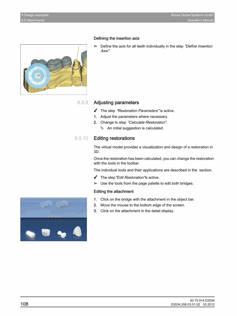
8 Design examples Sirona Dental Systems GmbH8.5 Attachments Operator's Manual
Define Insertion Axis
Defining the insertion axis
➢ Define the axis for all teeth individually in the step "Define Insertion Axis".
8.5.9 Adjusting parametersAdjusting parametersInstructions
✔ The step "Restoration Parameters" is active.1. Adjust the parameters where necessary.2. Change to step "Calculate Restoration".
An initial suggestion is calculated.
8.5.10 Editing restorationsEditing restorationsGeneral
The virtual model provides a visualization and design of a restoration in 3D.
Once the restoration has been calculated, you can change the restoration with the tools in the toolbar.
The individual tools and their applications are described in the section.
✔ The step"Edit Restoration"is active.➢ Use the tools from the page palette to edit both bridges.
Editing the attachment
1. Click on the bridge with the attachment in the object bar.2. Move the mouse to the bottom edge of the screen.3. Click on the attachment in the detail display.
63 75 914 D3534108 D3534.208.03.01.02 03.2012

Sirona Dental Systems GmbH 8 Design examplesOperator's Manual
båÖäáëÜ
The overlying tooth element is displayed transparent.
4. Select the "Move"tool and place the attachment in a suitable location. Be careful to maintain the occlusal distance. Important:Unsuitable placement. The position of the attachment is checked after you close the tool. The attachment is then displayed in red if the positioning can cause problems.
5. Select the tool"Subtract Attachment from Pontic"and click on the attachment. The overlying tooth element is then adapted so that it can be slid onto the attachment.
8.5.11 Grinding the restorationGrinding the restoration
Perform the following steps for both bridges.
Instructions
1. In step"Milling Unit", select the tool with which the restoration needs to be ground.
2. In step "Change Block Size", change the block size, where necessary.
3. In step"Adjust Mill Position", position the restoration in the block, where necessary.
4. Start the milling process.
63 75 914 D3534D3534.208.03.01.02 03.2012 109
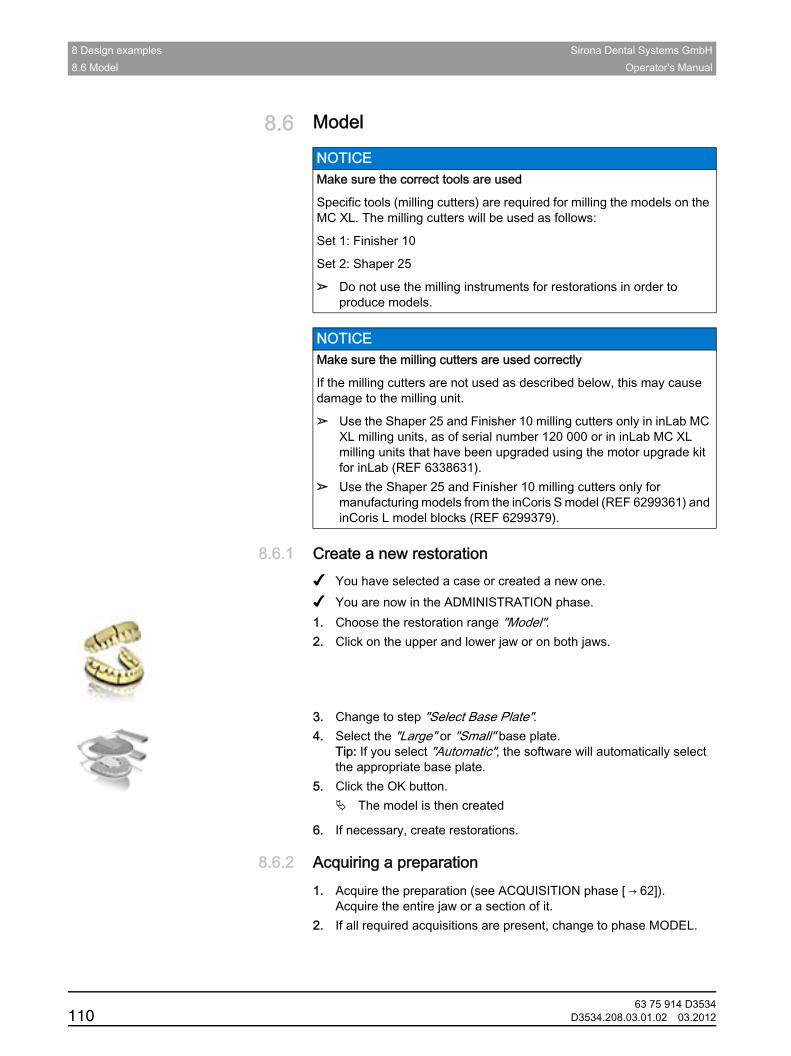
8 Design examples Sirona Dental Systems GmbH8.6 Model Operator's Manual
8.6 ModelModelCAUTION when using milling cutters
Fragment CAUTION Using milling cutters in inLab
8.6.1 Create a new restorationCreate a new restoration Model
✔ You have selected a case or created a new one.✔ You are now in the ADMINISTRATION phase.1. Choose the restoration range "Model".2. Click on the upper and lower jaw or on both jaws.
3. Change to step "Select Base Plate".4. Select the "Large" or "Small" base plate.
Tip: If you select "Automatic", the software will automatically select the appropriate base plate.
5. Click the OK button.The model is then created
6. If necessary, create restorations.
8.6.2 Acquiring a preparationAcquiring a preparation
1. Acquire the preparation (see ACQUISITION phase [ → 62]).Acquire the entire jaw or a section of it.
2. If all required acquisitions are present, change to phase MODEL.
NOTICE Make sure the correct tools are used
Specific tools (milling cutters) are required for milling the models on the MC XL. The milling cutters will be used as follows:
Set 1: Finisher 10
Set 2: Shaper 25
➢ Do not use the milling instruments for restorations in order to produce models.
NOTICE Make sure the milling cutters are used correctly
If the milling cutters are not used as described below, this may cause damage to the milling unit.
➢ Use the Shaper 25 and Finisher 10 milling cutters only in inLab MC XL milling units, as of serial number 120 000 or in inLab MC XL milling units that have been upgraded using the motor upgrade kit for inLab (REF 6338631).
➢ Use the Shaper 25 and Finisher 10 milling cutters only for manufacturing models from the inCoris S model (REF 6299361) and inCoris L model blocks (REF 6299379).
63 75 914 D3534110 D3534.208.03.01.02 03.2012
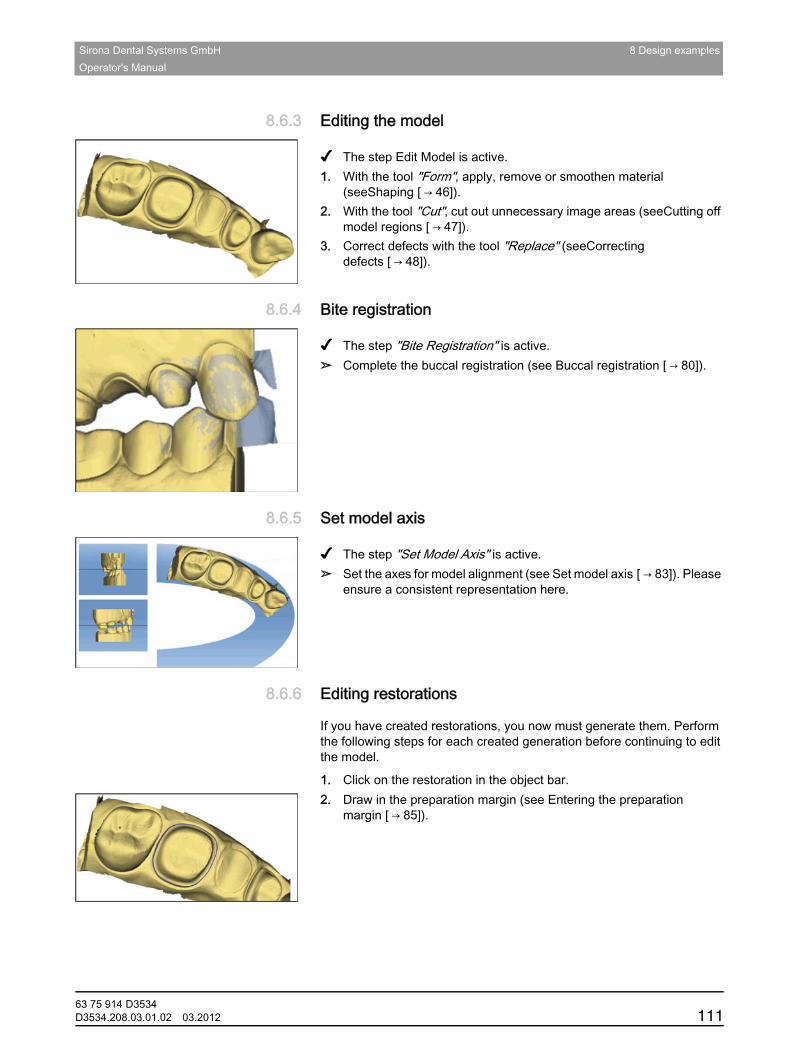
Sirona Dental Systems GmbH 8 Design examplesOperator's Manual
båÖäáëÜ
8.6.3 Editing the modelEditing the model
Instructions
✔ The step Edit Model is active.1. With the tool "Form", apply, remove or smoothen material
(seeShaping [ → 46]).2. With the tool "Cut", cut out unnecessary image areas (seeCutting off
model regions [ → 47]).3. Correct defects with the tool "Replace" (seeCorrecting
defects [ → 48]).
8.6.4 Bite registrationBite registration
Instructions
✔ The step "Bite Registration" is active.➢ Complete the buccal registration (see Buccal registration [ → 80]).
8.6.5 Set model axisSet model axis
Instructions
✔ The step "Set Model Axis" is active.➢ Set the axes for model alignment (see Set model axis [ → 83]). Please
ensure a consistent representation here.
8.6.6 Editing restorationsEditing restorations
If you have created restorations, you now must generate them. Perform the following steps for each created generation before continuing to edit the model.
1. Click on the restoration in the object bar.2. Draw in the preparation margin (see Entering the preparation
margin [ → 85]).
63 75 914 D3534D3534.208.03.01.02 03.2012 111
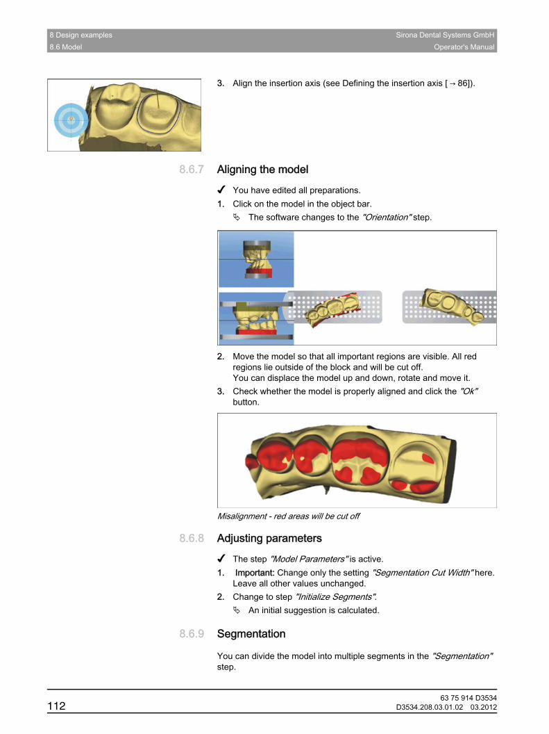
8 Design examples Sirona Dental Systems GmbH8.6 Model Operator's Manual
3. Align the insertion axis (see Defining the insertion axis [ → 86]).
8.6.7 Aligning the modelAligning the model
✔ You have edited all preparations.1. Click on the model in the object bar.
The software changes to the "Orientation" step.
2. Move the model so that all important regions are visible. All red regions lie outside of the block and will be cut off.You can displace the model up and down, rotate and move it.
3. Check whether the model is properly aligned and click the "Ok" button.
Misalignment - red areas will be cut off
8.6.8 Adjusting parametersAdjusting parameters
✔ The step "Model Parameters" is active.1. Important: Change only the setting "Segmentation Cut Width" here.
Leave all other values unchanged.2. Change to step "Initialize Segments".
An initial suggestion is calculated.
8.6.9 SegmentationSegmentation
You can divide the model into multiple segments in the "Segmentation" step.
63 75 914 D3534112 D3534.208.03.01.02 03.2012
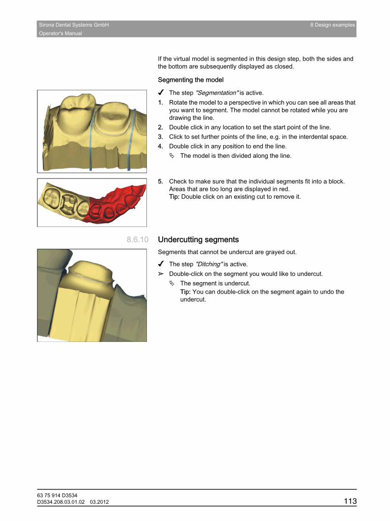
Sirona Dental Systems GmbH 8 Design examplesOperator's Manual
båÖäáëÜ
If the virtual model is segmented in this design step, both the sides and the bottom are subsequently displayed as closed.
Segmenting the model
✔ The step "Segmentation" is active.1. Rotate the model to a perspective in which you can see all areas that
you want to segment. The model cannot be rotated while you are drawing the line.
2. Double click in any location to set the start point of the line.3. Click to set further points of the line, e.g. in the interdental space.4. Double click in any position to end the line.
The model is then divided along the line.
5. Check to make sure that the individual segments fit into a block. Areas that are too long are displayed in red.Tip: Double click on an existing cut to remove it.
8.6.10 Undercutting segmentsUndercutting segmentsSegments that cannot be undercut are grayed out.
✔ The step "Ditching" is active.➢ Double-click on the segment you would like to undercut.
The segment is undercut.Tip: You can double-click on the segment again to undo the undercut.
63 75 914 D3534D3534.208.03.01.02 03.2012 113
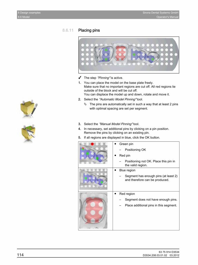
8 Design examples Sirona Dental Systems GmbH8.6 Model Operator's Manual
8.6.11 Placing pinsPlacing pins
✔ The step "Pinning" is active.1. You can place the model on the base plate freely.
Make sure that no important regions are cut off. All red regions lie outside of the block and will be cut off.You can displace the model up and down, rotate and move it.
2. Select the "Automatic Model Pinning" tool.The pins are automatically set in such a way that at least 2 pins with optimal spacing are set per segment.
3. Select the "Manual Model Pinning" tool.4. In necessary, set additional pins by clicking on a pin position.
Remove the pins by clicking on an existing pin.5. If all regions are displayed in blue, click the OK button.
● Green pin
– Positioning OK
● Red pin
– Positioning not OK. Place this pin in the valid region.
● Blue region
– Segment has enough pins (at least 2) and therefore can be produced.
● Red region
– Segment does not have enough pins.
– Place additional pins in this segment.
63 75 914 D3534114 D3534.208.03.01.02 03.2012
Sirona Dental Systems GmbH 8 Design examplesOperator's Manual
båÖäáëÜ
8.6.12 Closing the modelClosing the model
1. Click on the "MILL" phase.2. The model segments are calculated.
The software changes to the step "Preview".3. Check the preview and go back to make changes if necessary.4. Change to step "Export".5. Click the "Stack Restoration" button to export the model for the inLab
Stack software.
6. Click the "File Restoration" button to save a stack file (*.cam) or an Infinident file (*.i.lab) to any folder.
63 75 914 D3534D3534.208.03.01.02 03.2012 115
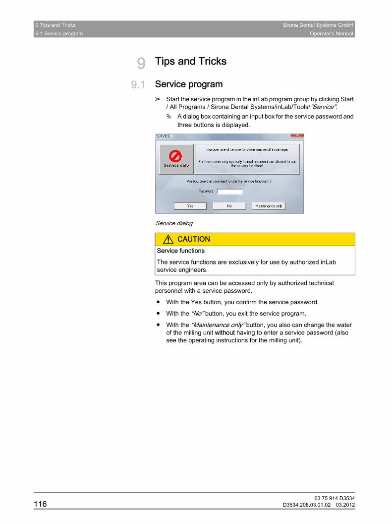
9 Tips and Tricks Sirona Dental Systems GmbH9.1 Service program Operator's Manual
9 Tips and TricksTips and Tricks
9.1 Service programService program
➢ Start the service program in the inLab program group by clicking Start / All Programs / Sirona Dental Systems/inLab/Tools/"Service".
A dialog box containing an input box for the service password and three buttons is displayed.
Service dialog
This program area can be accessed only by authorized technical personnel with a service password.
● With the Yes button, you confirm the service password.
● With the "No" button, you exit the service program.
● With the "Maintenance only" button, you also can change the water of the milling unit without having to enter a service password (also see the operating instructions for the milling unit).
CAUTIONService functions
The service functions are exclusively for use by authorized inLab service engineers.
63 75 914 D3534116 D3534.208.03.01.02 03.2012
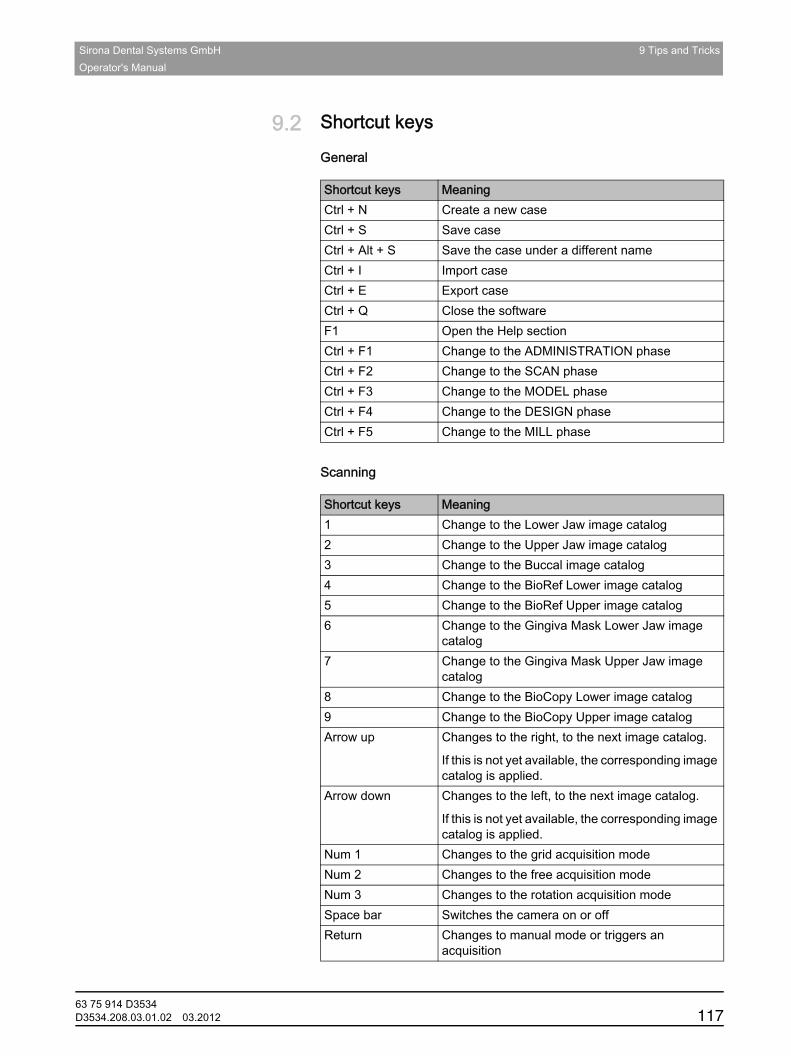
Sirona Dental Systems GmbH 9 Tips and TricksOperator's Manual
båÖäáëÜ
9.2 Shortcut keysShortcut keys
General
Scanning
Scanning
Shortcut keys MeaningCtrl + N Create a new caseCtrl + S Save caseCtrl + Alt + S Save the case under a different nameCtrl + I Import caseCtrl + E Export caseCtrl + Q Close the softwareF1 Open the Help sectionCtrl + F1 Change to the ADMINISTRATION phaseCtrl + F2 Change to the SCAN phaseCtrl + F3 Change to the MODEL phaseCtrl + F4 Change to the DESIGN phaseCtrl + F5 Change to the MILL phase
Shortcut keys Meaning1 Change to the Lower Jaw image catalog2 Change to the Upper Jaw image catalog3 Change to the Buccal image catalog4 Change to the BioRef Lower image catalog5 Change to the BioRef Upper image catalog6 Change to the Gingiva Mask Lower Jaw image
catalog7 Change to the Gingiva Mask Upper Jaw image
catalog8 Change to the BioCopy Lower image catalog9 Change to the BioCopy Upper image catalogArrow up Changes to the right, to the next image catalog.
If this is not yet available, the corresponding image catalog is applied.
Arrow down Changes to the left, to the next image catalog.
If this is not yet available, the corresponding image catalog is applied.
Num 1 Changes to the grid acquisition modeNum 2 Changes to the free acquisition modeNum 3 Changes to the rotation acquisition modeSpace bar Switches the camera on or offReturn Changes to manual mode or triggers an
acquisition
63 75 914 D3534D3534.208.03.01.02 03.2012 117
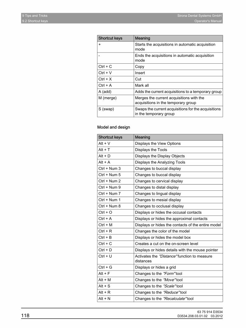
9 Tips and Tricks Sirona Dental Systems GmbH9.2 Shortcut keys Operator's Manual
Design
Model and design
+ Starts the acquisitions in automatic acquisition mode
- Ends the acquisitions in automatic acquisition mode
Ctrl + C CopyCtrl + V InsertCtrl + X CutCtrl + A Mark allA (add) Adds the current acquisitions to a temporary groupM (merge) Merges the current acquisitions with the
acquisitions in the temporary groupS (swap) Swaps the current acquisitions for the acquisitions
in the temporary group
Shortcut keys Meaning
Shortcut keys MeaningAlt + V Displays the View OptionsAlt + T Displays the ToolsAlt + D Displays the Display ObjectsAlt + A Displays the Analyzing ToolsCtrl + Num 3 Changes to buccal displayCtrl + Num 5 Changes to buccal displayCtrl + Num 2 Changes to cervical displayCtrl + Num 9 Changes to distal displayCtrl + Num 7 Changes to lingual displayCtrl + Num 1 Changes to mesial displayCtrl + Num 8 Changes to occlusal displayCtrl + O Displays or hides the occusal contactsCtrl + A Displays or hides the approximal contactsCtrl + M Displays or hides the contacts of the entire modelCtrl + R Changes the color of the modelCtrl + B Displays or hides the model boxCtrl + C Creates a cut on the on-screen levelCtrl + D Displays or hides details with the mouse pointerCtrl + U Activates the "Distance" function to measure
distancesCtrl + G Displays or hides a gridAlt + F Changes to the "Form" toolAlt + M Changes to the "Move" toolAlt + S Changes to the "Scale" toolAlt + R Changes to the "Reduce" toolAlt + N Changes to the "Recalculate" tool
63 75 914 D3534118 D3534.208.03.01.02 03.2012

Sirona Dental Systems GmbH 9 Tips and TricksOperator's Manual
båÖäáëÜ
Alt + C Changes to the "Contacts" toolAlt + U Resets the changes made with the toolCtrl + Z Restores the last change made by the toolAlt + 0 Closes the toolAlt + H Changes to the "Shape" toolAlt + X Changes to the "Split" tool
Shortcut keys Meaning
63 75 914 D3534D3534.208.03.01.02 03.2012 119
10 inLab Stack SW 4.0 Sirona Dental Systems GmbH10.1 Getting started Operator's Manual
10 inLab Stack SW 4.0inLab Stack SW 4.0
10.1 Getting startedGetting started
10.1.1 Installing the softwareInstalling the softwareAdministrator rights
✔ The PC is powered up and all programs are terminated.1. Insert the DVD into the DVD drive.
The setup program starts automatically.
2. If this is not the case, run the "Setup.exe" file in the root directory of the DVD.
The installation wizard opens.
3. Click on the "OK" button.4. In the next dialog box, click on the "Next" button.
The license agreement is shown.
5. Read through the license agreement carefully.6. If you accept the license agreement, then check the "I accept the
terms in the license agreement" option button and confirm your acceptance by clicking the "Next" button.
7. In the next dialog box, click on the "Next" button.8. In the next dialog box, click on the "Install" button.
The program continues the installation routine. This may take several minutes.
9. Following successful installation, click on the "Finish" button.The software is installed.
10.1.2 Copy protectionCopy protectionUSB license stick inLab
The software can be started only when the USB license stick is plugged in. The USB license stick is included in the scope of supply of the units. If you require additional licenses, please contact your dealer.
Always keep the USB license stick near the unit.
All authorizations (milling, interface, software licenses) can be installed as electronic licenses on the USB license stick. You must enter a 25-digit license key for this purpose.You will receive the license key along with the unit. Alternatively, you can order it separately from your dealer.
Following an update, you may require a new license that is not available on your USB license stick. For more information, refer to the section on License manager [ → 123].
NOTICE Installation only with administrator rights
You must have administrator rights on the PC on which you want to install the software!
63 75 914 D3534120 D3534.208.03.01.02 03.2012
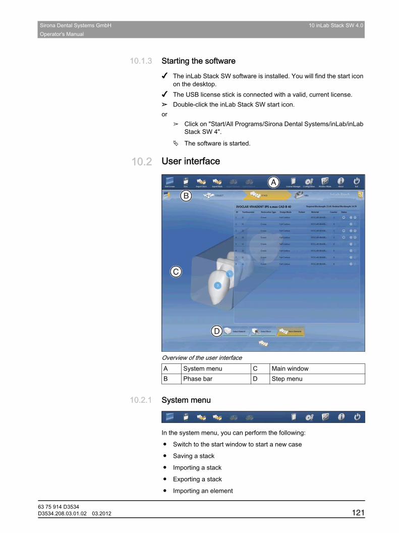
Sirona Dental Systems GmbH 10 inLab Stack SW 4.0Operator's Manual
båÖäáëÜ
10.1.3 Starting the softwareStarting the software
✔ The inLab Stack SW software is installed. You will find the start icon on the desktop.
✔ The USB license stick is connected with a valid, current license.➢ Double-click the inLab Stack SW start icon.or
➢ Click on "Start/All Programs/Sirona Dental Systems/inLab/inLab Stack SW 4".
The software is started.
10.2 User interfaceUser interface
Overview of the user interface
10.2.1 System menuSystem menuDescription: stack
In the system menu, you can perform the following:
● Switch to the start window to start a new case
● Saving a stack
● Importing a stack
● Exporting a stack
● Importing an element
A System menu C Main windowB Phase bar D Step menu
63 75 914 D3534D3534.208.03.01.02 03.2012 121
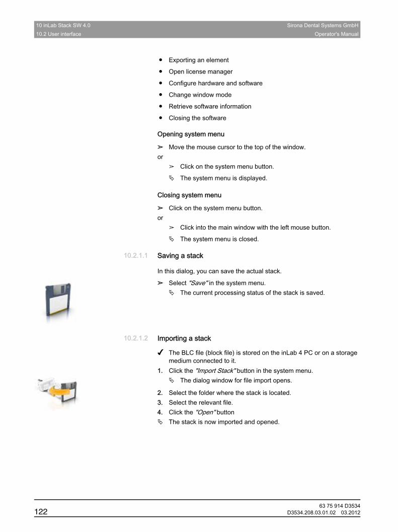
10 inLab Stack SW 4.0 Sirona Dental Systems GmbH10.2 User interface Operator's Manual
● Exporting an element
● Open license manager
● Configure hardware and software
● Change window mode
● Retrieve software information
● Closing the softwareOpening the system menu
Opening system menu
➢ Move the mouse cursor to the top of the window.or
➢ Click on the system menu button.
The system menu is displayed.Closing the system menu
Closing system menu
➢ Click on the system menu button.or
➢ Click into the main window with the left mouse button.
The system menu is closed.
10.2.1.1 Saving a stackSaving a stack
In this dialog, you can save the actual stack.
➢ Select "Save" in the system menu.The current processing status of the stack is saved.
10.2.1.2 Importing a stackImporting a stack
✔ The BLC file (block file) is stored on the inLab 4 PC or on a storage medium connected to it.
1. Click the "Import Stack" button in the system menu.The dialog window for file import opens.
2. Select the folder where the stack is located. 3. Select the relevant file.4. Click the "Open" button
The stack is now imported and opened.
63 75 914 D3534122 D3534.208.03.01.02 03.2012

Sirona Dental Systems GmbH 10 inLab Stack SW 4.0Operator's Manual
båÖäáëÜ
10.2.1.3 Exporting a stackExporting a stack
You can store a stack in any location.
✔ You have opened a stack in the software.1. Click the "Export Stack" button in the system menu.
The dialog window for file export opens.
2. Select the target folder to which you want to export the case.3. Assign any name to the stack.4. Click on the "Save" button.
The stack is exported as a BLC file.
If you would like to transfer the stack to another PC, you can use a USB stick or a network drive for this purpose.
10.2.1.4 Importing an elementImporting an element
✔ A stack is open.✔ The CAM file of a restoration is stored on the inLab 4 PC or on a
storage medium connected to it.1. Click the "Import Element" button in the system menu.
The dialog window for file import opens.
2. Select the folder where the restoration is located. 3. Select the relevant file.4. Click the "Open" button
The restoration is then imported and added.
10.2.1.5 Exporting an elementExporting an element
You can store a restoration in any location.
✔ You have opened a stack in the software.1. Click the "Export Element" button in the system menu.
The dialog window for file export opens.
2. Select the target folder to which you want to export the restoration.3. Assign any name to the restoration.4. Click on the "Save" button.
The restoration is exported as a CAM file.
If you would like to transfer the restoration to another PC, you can use a USB stick or a network drive for this purpose.
10.2.1.6 License managerLicense managerThe license manager is used for the installation of new software licenses on the USB license stick. To do this, start the license manager via the system menu and follow the instructions on the screen. Keep the license certificate with 25-digit license key ready, which you either obtained with the unit or ordered separately from your dealer.
To activate the license you must have an Internet connection and the USB license stick must be connected.
63 75 914 D3534D3534.208.03.01.02 03.2012 123
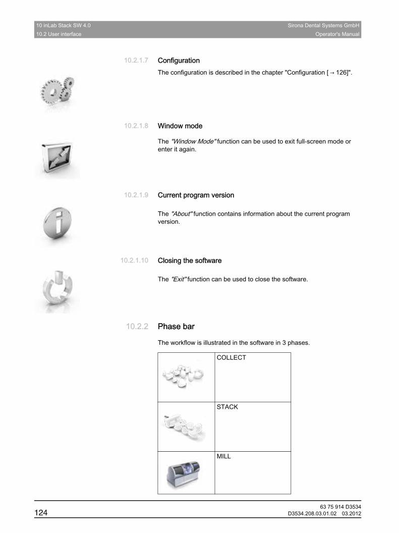
10 inLab Stack SW 4.0 Sirona Dental Systems GmbH10.2 User interface Operator's Manual
10.2.1.7 ConfigurationConfigurationThe configuration is described in the chapter "Configuration [ → 126]".
10.2.1.8 Window modeWindow mode
The "Window Mode" function can be used to exit full-screen mode or enter it again.
10.2.1.9 Current program versionCurrent program version
CEREC SW 4
The "About" function contains information about the current program version.
10.2.1.10 Closing the softwareClosing the software
Closing CEREC SW 4
The "Exit" function can be used to close the software.
10.2.2 Phase barPhase bar
The workflow is illustrated in the software in 3 phases.
COLLECT
STACK
MILL
63 75 914 D3534124 D3534.208.03.01.02 03.2012
Sirona Dental Systems GmbH 10 inLab Stack SW 4.0Operator's Manual
båÖäáëÜ
10.2.3 Start windowStart window
In the start window, you can perform the following:
● Creating new stacks
● Opening stacks
● Deleting stacks
Switching to the start view
You can switch to the start view at any time.
1. Open the system menu.2. Click on the "Start Screen" button.
10.2.3.1 Creating a new stackCreating a new stack1. Click on the step "New Stack".
You will be prompted to provide details.
2. Change the name and date if necessary.3. Click on the "Ok" button.
The program switches over to the "COLLECT" phase.
10.2.3.2 Opening a stackOpening a stack
✔ You have found the stack in the overview.1. Click on the stack.2. Click on the "Open Stack" step in the step menu.
The stack opens.
10.2.3.3 Removing a stackRemoving a stack✔ You have found the stack in the overview.1. Click on the stack.2. Click on the "Delete Stack" step in the step menu.3. Confirm the deletion by clicking the "Ok" button.
The stack is deleted.
10.2.4 Step menuStep menuGeneral description
Each phase is divided into steps. They are shown in the step menu at the bottom edge of the screen. The step menu changes depending on which phase the current restoration is in.
This menu guides you through the process step-by-step.Mandatory steps
Mandatory steps
Mandatory steps are marked with a red or green bar.
Red bar: The step has not yet been completed successfully.Green bar: The step has been completed successfully.
63 75 914 D3534D3534.208.03.01.02 03.2012 125
10 inLab Stack SW 4.0 Sirona Dental Systems GmbH10.3 Configuration Operator's Manual
10.3 ConfigurationConfigurationThe "Configuration" menu contains three sub-menus:
● Parameters
● Devices
● Options
10.3.1 ParametersParametersIn the"Parameters"menu, you can adapt the presettings for the milling process.
The changes in the values are displayed graphically.
Crown, inlay, onlay and veneer
Applying/discarding settings
Accepting settings
➢ Click on the "Ok" button.
Discarding settings
➢ Click on the "Cancel" button.Resetting settings
Resetting settings
➢ Click on the "Reset All Group Parameter" button.The settings for this restoration type are reset to the factory settings.
Parameters Description Default value
Horizontal Connector ● Additionally generates a horizontal connection
● Can be switched on and off
NO
Connector Diameter ● Sets the diameter of the connector
3.0 mm
Restoration Distance ● Sets the horizontal distance of the restorations from each other
1.2 mm
63 75 914 D3534126 D3534.208.03.01.02 03.2012
Sirona Dental Systems GmbH 10 inLab Stack SW 4.0Operator's Manual
båÖäáëÜ
10.3.2 DevicesDevicesAll connected devices can be displayed and configured under the menu item "Devices".A green check mark on a device indicates its availability.Adding devices (automatically)
Adding devices automatically
You can add additional devices with the "Scan for New Devices" function.
✔ The device is attached to the PC.1. Click on the "Scan for New Devices" button.
All devices attached to the PC are detected. You will be prompted to enter a name for new devices.
2. Enter a name for the new device.Adding devices (manually)
Adding devices (manually)
You can manually add devices with the "Add Device (Manual)" function. This is mandatory for devices which cannot be operated at the maximum speed of 115,200 baud. This applies to devices with long cable connections or certain radio modules (e.g. Futaba, 19200 baud).
1. Click on the "Add Device (Manual)" button.2. Select whether the device is connected to the network or in series.3. Network: Enter the network address.
In series: Enter the COM port and the baud rate.4. Click on the "Ok" button.
The software attempts to contact the device.
If the connection fails, check that it is correctly established. If necessary, contact a qualified technician.Refreshing CEREC SW 4
Refresh status
With the "Refresh Devices" button, you can
● refresh the status display, e.g. check whether a milling unit has finished milling or
● check the current availability of a device.
10.3.3 OptionsOptionsThe menu item "Options" has the following subitems:Options of inLab Stack SW 4
● Select odontogram
● Reset notes
● Legend proof
● Display legend
● Generate name automatically
● Calculate stacks automatically
63 75 914 D3534D3534.208.03.01.02 03.2012 127
10 inLab Stack SW 4.0 Sirona Dental Systems GmbH10.3 Configuration Operator's Manual
10.3.3.1 OdontogramOdontogram
You can set the odontogram using "ADA/FDI Notation":● International ("FDI Notation")● USA ("ADA Notation")
10.3.3.2 Reset notesReset notes
Here, all warnings can be displayed again.
10.3.3.3 Legend proofLegend proof
Here you can select whether a legend will be generated. This option can be used to output a legend of the restorations with the respective order information.
10.3.3.4 Display legendDisplay legend
Here you can select whether a legend will be displayed following the milling process.
10.3.3.5 Generate name automaticallyGenerate name automatically
Here you can select whether a stack name will be generated automatically.
10.3.3.6 Calculate stacks automaticallyCalculate stacks automatically
Here you can select whether a stack name will be generated automatically.
Setting DescriptionYES Displays all the deactivated warnings in the workflow
again.NO Warnings which were previously hidden, remain hidden.
Setting DescriptionYES A legend will be generated.NO No legend will be generated.
Setting DescriptionYES A legend will be displayed.NO No legend will be displayed.
Setting DescriptionYES The stacks are automatically inserted in the block
following the change to the STACK phase.NO The stacks must be inserted in the block manually in the
Stack Elements step.
63 75 914 D3534128 D3534.208.03.01.02 03.2012
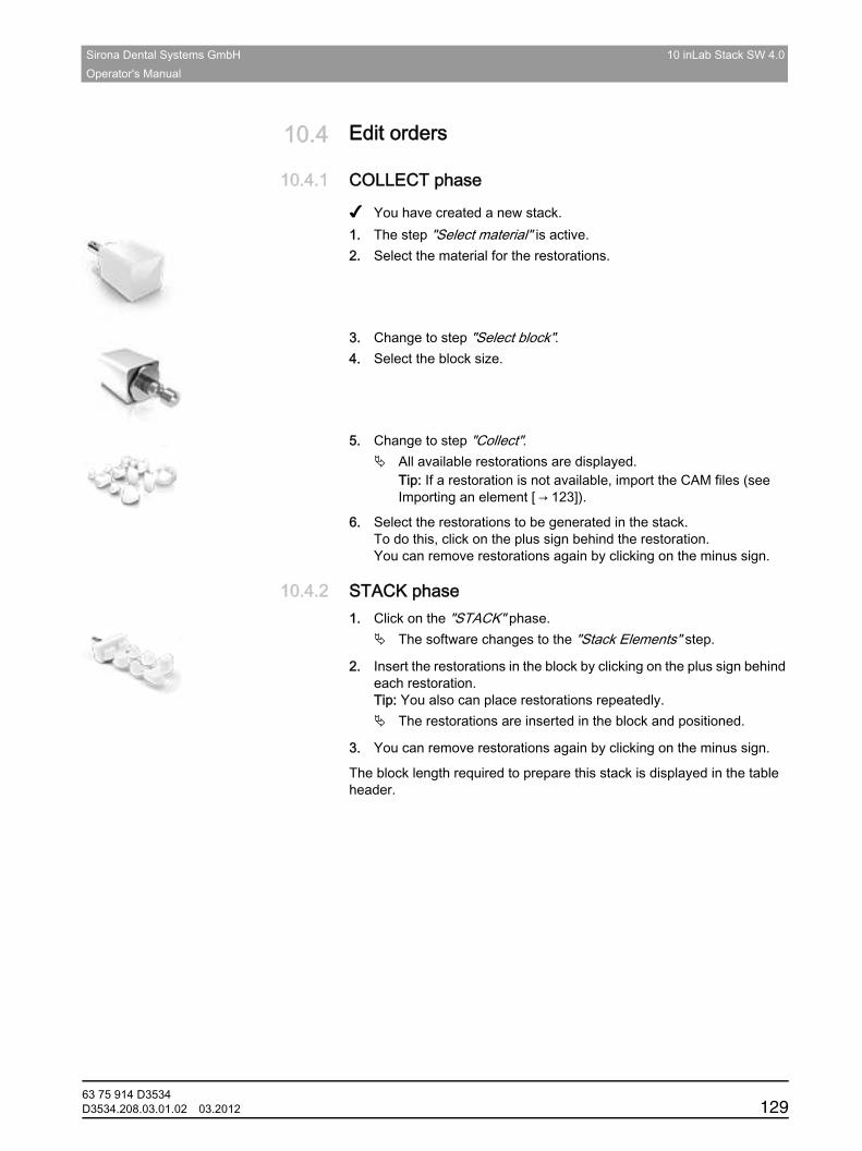
Sirona Dental Systems GmbH 10 inLab Stack SW 4.0Operator's Manual
båÖäáëÜ
10.4 Edit ordersEdit orders
10.4.1 COLLECT phaseCOLLECT phase
✔ You have created a new stack.1. The step "Select material" is active.2. Select the material for the restorations.
3. Change to step "Select block".4. Select the block size.
5. Change to step "Collect".All available restorations are displayed.Tip: If a restoration is not available, import the CAM files (see Importing an element [ → 123]).
6. Select the restorations to be generated in the stack.To do this, click on the plus sign behind the restoration.You can remove restorations again by clicking on the minus sign.
10.4.2 STACK phaseSTACK phase1. Click on the "STACK" phase.
The software changes to the "Stack Elements" step.
2. Insert the restorations in the block by clicking on the plus sign behind each restoration.Tip: You also can place restorations repeatedly.
The restorations are inserted in the block and positioned.
3. You can remove restorations again by clicking on the minus sign.
The block length required to prepare this stack is displayed in the table header.
63 75 914 D3534D3534.208.03.01.02 03.2012 129
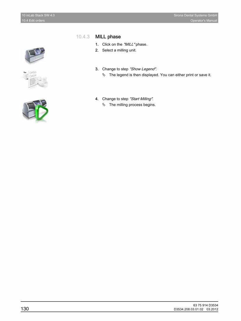
10 inLab Stack SW 4.0 Sirona Dental Systems GmbH10.4 Edit orders Operator's Manual
10.4.3 MILL phaseMILL phase1. Click on the "MILL" phase.2. Select a milling unit.
3. Change to step "Show Legend".The legend is then displayed. You can either print or save it.
4. Change to step "Start Milling".The milling process begins.
63 75 914 D3534130 D3534.208.03.01.02 03.2012
Sirona Dental Systems GmbH 11 Sirona Connect portalOperator's Manual
båÖäáëÜ
11 Sirona Connect portalSirona Connect portal
11.1 Starting the Sirona Connect portalStarting the Sirona Connect portal
✔ The start screen is active.➢ Click the"CEREC Connect Portal"button on the step by step menu.
The login window is displayed.
11.2 Log in to the portalLog in to the portal
1. Enter user name and password.2. Activate the relevant option if you want to save the user name and
password.3. In the step menu, click on "Ok".
The data are uploaded in parallel to the information being entered in the portal.
11.3 Order listOrder list
You can filter the orders by the various statuses via the filter below the list.
In order to view the order details you must click the relevant order in the list so that it is highlighted in orange. Then you can view the details by clicking on "View Order" in the step menu.
11.4 Restoration dataRestoration data
Cases with several restorations are always fully displayed and downloaded.
Data on individual restorations is shown to the left of the overview display. The active restoration is colored orange in the overview and is displayed in white in the model.
Now click"Order Data"to proceed to the next step.
11.5 Order informationOrder information
The delivery date, potential delivery time, and dentist placing the order are displayed here.
Now click"Additional Instructions"to proceed to the next step.
63 75 914 D3534D3534.208.03.01.02 03.2012 131
11 Sirona Connect portal Sirona Dental Systems GmbH11.6 Additional information Operator's Manual
11.6 Additional informationAdditional information
In this step you can find information on the patient's sex, age, and type of insurance cover (applies only to Germany).
The dentist can enter additional information in "Additional Instructions", in the form of flowing text.
The"Additional Files"function can be used to download the additional data (e.g. photos) that the dentist has attached. To do so, click the file and save it accordingly.
Now click"View Work Ticket"to proceed to the next step.
11.7 Displaying the order sheetDisplaying the order sheet
In this step, the order sheet is displayed and saved.
Click the printer icon to print the order sheet.
To zoom in and out of the order sheet display, you can click the corresponding magnifying glass icon.
The icon underneath the magnifying glass can be used to scale the order sheet to the window size.
Now click"Check Model"to proceed to the next step.
11.8 Checking the modelChecking the model
In this step, the model is downloaded to the software for checking.
Analysis tools
Using the"Analyzing Tools", you can display the model contacts or hide the model box.
Display objects
Using"Display Objects", you can display the individual image fields.
Using"Display Objects", you can also check additional image data that the dentist may have recorded (e.g."BioCopy Lower") by clicking on the corresponding buttons.
The transparency of the image fields can be minutely adjusted using the button for each image field. To do so, hold the button down with the left mouse button and move the mouse up or down.
Now click "Accept"to proceed to the next step.
63 75 914 D3534132 D3534.208.03.01.02 03.2012
Sirona Dental Systems GmbH 11 Sirona Connect portalOperator's Manual
båÖäáëÜ
11.9 Accepting/rejecting an orderAccepting/rejecting an order
In this step, you can reject or accept the order.
The restoration data is shown to the left of the overview display and to the top right, the dentist placing the order.
Using"My comments", you can send the dentist a message.
In the step by step menu, you can click on"Yes"to accept the order or"No"to reject it. The dentist receives a confirmation email which also includes your comments.
Then the order list reappears automatically.
11.10 Order list appears automaticallyOrder list appears automatically
In this step, you can either examine the next order or download the model for construction to the inLab software, using the"Load Order"button.
63 75 914 D3534D3534.208.03.01.02 03.2012 133
Sirona Dental Systems GmbH Operator's Manual
IndexBBars
Cylindric, 42
Dolder, 42
Hader, 42
Squared, 42
Biogeneric morphology, 52
Buccal registration
Displacing an image, 46
Rotating an image, 46
CCase
Import, 21
Color scheme, 58
contact surfaces
Virtual model, 58
Contact surfaces
Restoration, 58
Contacts, 52
Cut
Invert model area, 48
Remove model area, 47
DDesign
Anatomic, 51
Manual, 51
Scale all, 52
Size, 52
Design mode
Anatomic, 42
Bars, 42
Biogeneric Copy, 41
Biogeneric Individual, 41
Biogeneric Reference, 41
Framework, 42
Intersection, 42
Telescope, 42
Display objects
BioCopy LJ, 57
BioCopy UJ, 56
BioReference LJ, 57
BioReference UJ, 57
Gingival mask LJ, 57
Gingival mask UJ, 57
Implant, 57, 57
Lower jaw, 56
Minimum thickness, 56
Restoration, 56
Transparency, 56, 56
Trimmed model, 56
Upper jaw, 56
63 75 914 D3534D3534.208.03.01.02 03.2012 134
Sirona Dental Systems GmbH Operator's Manual
EElement
Export, 123
Import, 123
Entering the preparation margin, 85
Automatic, 49
Manual, 50
Manual with intensity image, 50
FFile format
LAB, 13
Older formats, 13
Form
Apply material, 46
Modifying the size, 47
Remove material, 47
Smooth, 47
Iimage regions
trimming, 84
MManual
html format, 12
PDF format, 12
Model
Trim preparation, 83
Move
Displace, 53
Turn, 53
Oodontogram
ADA, 13
FDI, 13
Optical impression
End teeth, 74
Quadrant restoration, 74
PPhase
MODEL, 80
Position
Displace, 50
Positioning
Rotation, 51
63 75 914 D3534135 D3534.208.03.01.02 03.2012
Sirona Dental Systems GmbH Operator's Manual
RReset contact surfaces, 52
Restoration
Cuts, 59
Display height and thickness, 60
Export, 21
Measure distance, 60
Save, 20
Save as, 21
Restoration type
Abutment, 39
Attachment, 41
Bar, 41
Bridge restoration, 40
Connector, 40
Crown, 39
Inlay/onlay, 39
Missing, 40
Model, 41, 41
Pontic, 40
Single tooth restoration, 39
Veneer, 39
Rotate
Buccal image, 82
Lower jaw and upper jaw, 81
SSafety information, 11
Scale
Modifying the size, 54
Show approximal contacts in color, 59
Show bottom, 58
Show occlusal contacts in color, 59
Show side areas, 58
Show the restoration in model color, 59
Software
Uninstallation, 14
Stack
Export, 123
Import, 122
Save, 122
Supplementary optical impressions, 73
TTool
Biogeneric variation, 52
Buccal registration, 46
Contacts, 52
Cut, 47
Design, 51
Entering the preparation margin, 49
Form, 46
Move, 53
Position, 50
Replace, 48
Reset model, 48
Sprue location, 52
Trim, 49
Tool wheel, 19, 55
Tools, 45
Trim
Discard part, 49
Invert selection, 49
63 75 914 D3534D3534.208.03.01.02 03.2012 136

Sirona Dental Systems GmbH Operator's Manual
VViews, 45
Change, 45
Enlarge, 45
Reduce, 45
63 75 914 D3534137 D3534.208.03.01.02 03.2012

tÉ=êÉëÉêîÉ=íÜÉ=êáÖÜí=íç=ã~âÉ=~åó=~äíÉê~íáçåë=ïÜáÅÜ=ã~ó=ÄÉ=êÉèìáêÉÇ=ÇìÉ=íç=íÉÅÜåáÅ~ä=áãéêçîÉãÉåíëK
«=páêçå~=aÉåí~ä=póëíÉãë=dãÄe=OMNO péê~ÅÜÉW ÉåÖäáëÅÜ mêáåíÉÇ=áå=dÉêã~åóaPRPQKOMUKMPKMNKMO MPKOMNO ûKJkêKW= MMM=MMM
páêçå~=aÉåí~ä=póëíÉãë=dãÄeáå=íÜÉ=rp^W
c~Äêáâëíê~≈É=PNSQSOR=_ÉåëÜÉáãdÉêã~åóïïïKëáêçå~KÅçã
páêçå~=aÉåí~ä=póëíÉãë=ii`QUPR=páêçå~=aêáîÉI=pìáíÉ=NMM`Ü~êäçííÉI=k`=OUOTPrp^
lêÇÉê=kç SP=TR=VNQ=aPRPQ